USER MANUAL - resqtec.com · USER MANUAL PROFIX MAX ... We are condent that the design of this...
55
USER MANUAL PROFIX MAX STABILIZATION SYSTEM ENGLISH ORIGINAL RESQTEC USER MANUAL WWW.RESQTEC.COM
Transcript of USER MANUAL - resqtec.com · USER MANUAL PROFIX MAX ... We are condent that the design of this...

USER MANUALPROFIX MAX STABILIZATION SYSTEM
ENGLISH ORIGINAL RESQTEC USER MANUAL
WWW.RESQTEC.COM
USER MANUAL PROFIX MAX STABILIZATION SYSTEM
02 Resqtec Manual ProFix Max (DM058K06)
1. INTRODUCTION: SAFETY FIRST! 041.1. Safety messages 041.2. General safety information 041.3. Safety information 051.4. Productidentification 051.5. Applicable types 05
2. PRODUCT SUMMARY 062.1. Introduction 062.2. ProFix Max description 062.3. ProFixMaxcomponentidentification 062.4. Handheldcontrollercomponentidentification 072.5. Pressureregulatorcomponentidentification 07
3. PRODUCT RANGE 083.1. Products & accessories 08
4. GENERAL OPERATING INSTRUCTIONS 134.1. Initial use 134.2. Preparation before use 134.3. The locking device 144.4. Operating the ProFix Max 154.5. (Dis)connecting an attachment 164.6. (Dis)connectingaPowerPlatetoaMultiSwivel 174.7. UsingtheProFixMaxbottomring 184.8. Connecting pneumatics 194.9. Disconnecting pneumatics 194.10. Connecting the pressure regulator 204.11. Disconnecting the pressure regulator 214.12. Pneumatically follow load moving upwards 224.13. Pneumatically follow load moving downwards 244.14. Depressurizing the ProFix Max 25
5. MAINTENANCE & STORAGE 265.1. TechnicalspecificationsProFixMax 265.2. Technicalspecificationsextensions 275.3. LoadchartsProFixMax 275.4. Tabulated data – trenches and/or excavations 32
6. WARNINGS & LIMITATIONS 366.1. Maintenance after use 366.2. Regularmaintenance 376.3. Annual maintenance 386.4. Recommended storage 38 7.TROUBLESHOOTING 397.1. Generalinstructions 397.2. Extensions 397.3. Hydraulicrams 427.4. V4EDDram 437.5. PowerPusherram 447.6. Multi-connectorwithramadapter 457.7. Avoidnon-symmetricloading 467.8. SideloadingProFixMax 467.9. BucklingofProFixMax 467.10. Angledloads 47

03
USER MANUAL PROFIX MAX STABILIZATION SYSTEM
Resqtec Manual ProFix Max (DM058K06)
8.TROUBLESHOOTING 51
9. WARRANTY 52
10. DISCLOSURE 53
11. CONTACT 54
USER MANUAL PROFIX MAX STABILIZATION SYSTEM
04 Resqtec Manual ProFix Max (DM058K06)
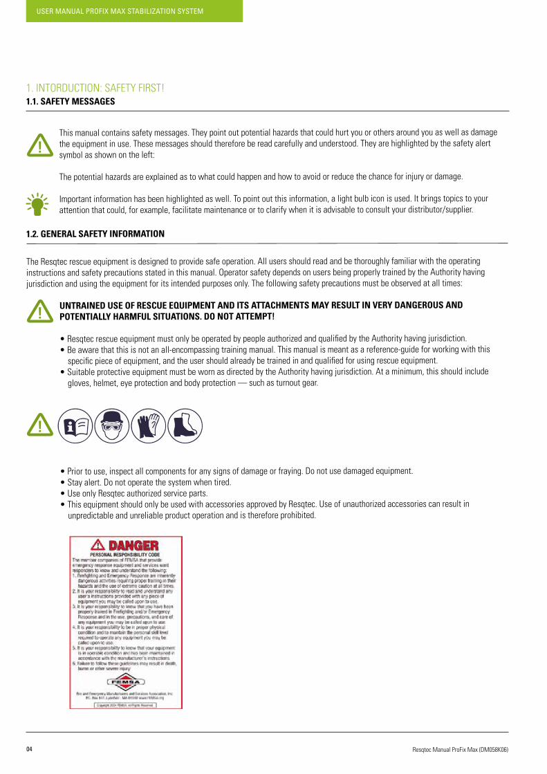
1. INTORDUCTION: SAFETY FIRST!1.1. SAFETY MESSAGES
This manual contains safety messages. They point out potential hazards that could hurt you or others around you as well as damage the equipment in use. These messages should therefore be read carefully and understood. They are highlighted by the safety alert symbol as shown on the left: The potential hazards are explained as to what could happen and how to avoid or reduce the chance for injury or damage.
Important information has been highlighted as well. To point out this information, a light bulb icon is used. It brings topics to your attention that could, for example, facilitate maintenance or to clarify when it is advisable to consult your distributor/supplier.
1.2. GENERAL SAFETY INFORMATION
The Resqtec rescue equipment is designed to provide safe operation. All users should read and be thoroughly familiar with the operatinginstructions and safety precautions stated in this manual. Operator safety depends on users being properly trained by the Authority havingjurisdiction and using the equipment for its intended purposes only. The following safety precautions must be observed at all times:
UNTRAINED USE OF RESCUE EQUIPMENT AND ITS ATTACHMENTS MAY RESULT IN VERY DANGEROUS AND POTENTIALLY HARMFUL SITUATIONS. DO NOT ATTEMPT!
•ResqtecrescueequipmentmustonlybeoperatedbypeopleauthorizedandqualifiedbytheAuthorityhavingjurisdiction. •Beawarethatthisisnotanall-encompassingtrainingmanual.Thismanualismeantasareference-guideforworkingwiththis specificpieceofequipment,andtheusershouldalreadybetrainedinandqualifiedforusingrescueequipment. • Suitable protective equipment must be worn as directed by the Authority having jurisdiction. At a minimum, this should include gloves, helmet, eye protection and body protection — such as turnout gear.
• Prior to use, inspect all components for any signs of damage or fraying. Do not use damaged equipment. • Stay alert. Do not operate the system when tired. • Use only Resqtec authorized service parts. • This equipment should only be used with accessories approved by Resqtec. Use of unauthorized accessories can result in unpredictable and unreliable product operation and is therefore prohibited.

05
USER MANUAL PROFIX MAX STABILIZATION SYSTEM
Resqtec Manual ProFix Max (DM058K06)
1.3. SAFETY INFORMATION
Beforeusingtheequipmentanditsrelatedproductsandaccessories,conductanoverallsize-upoftheintendeduseandsafeguardagainstpotential hazards before installing the product. Read and understand this manual before using the equipment.
The WARNING and SAFETY labels on the product alert the user to special hazards inherent with its use. Should they become damaged or unreadable, contact the manufacturer to obtain a replacement.
BEFORE INSTALLING THE EQUIPMENT, BE AWARE OF THE FOLLOWING:
• ProFix Max is designed only for stabilizing objects. Never use to dislodge or lift an object on its own. • Compressed air may be applied in situations where the load may be moving upwards. The use of high (air) pressures (>2 bar / 29 PSI) may be applied only in trench shoring applications • The ProFix Max is impossible to release when any kind of axial load is working it. Remove all axial loads before release. • The ProFix Max expands rapidly when air is applied. Stay clear of ends. •TheProFixMaxhasbeendesignedtosupportloadspushingagainstitsendsonly.Neverside-loadtheProFixMax,useitasastep or hang something on it.
1.4. PRODUCT IDENTIFICATION
Productidentificationistomakesurethatthismanualcomeswithaspecificproductandthatthismanualshouldalwaysbeavailableasareferenceguidetothatproduct.Itismandatorythatthismanualandaccompanying“ServiceBooklet”arenotseparatedfromtheequipmentspecifiedbelowduringitsservicelife.ThismanualcomeswithResqtecproducttype:
1.5. APPLICABLE TYPES
This manual covers the following product types:
PXM
Distributor/Supplier information:
With serial number:
ARTICLE NUMBER NAME
8410.0290.00 ProFixMax470
8410.0300.20 ProFix Max 600
8410.0310.20 ProFix Max 880
8410.0320.20 ProFix Max 1400
8410.0330.20 ProFix Max 2300
USER MANUAL PROFIX MAX STABILIZATION SYSTEM
06 Resqtec Manual ProFix Max (DM058K06)
2. PRODUCT SUMMARY2.1. INTRODUCTION
ThankyouforchoosingResqtec.Weareconfidentthatweliveuptoyourexpectations.Thismanualhasbeencompiledcarefullytosupplythereader with all the necessary information. Read all the instructions before using the equipment to assure safe and optimal use of the equipment. These instructions contain aspects relevant to safe and optimal use of the equipment. The unit has been manufactured by Resqtec Zumro. For addresses, please refer to the last page of this manual or refer to our website,www.resqtec.com.
2.2. PRODUCT DESCRIPTION
TheProFixMaxmanualandpneumaticshoringdevicehasbeendesignedandengineeredtoassistfirefighters,USAR-teamsandotherrescueworkerswiththevariousshoringapplicationstheyencounter.Weareconfidentthatthedesignofthisproductwillenablethoseworkingintheseenvironments to not only negotiate the obstacles they encounter, but to perform their work more safely.
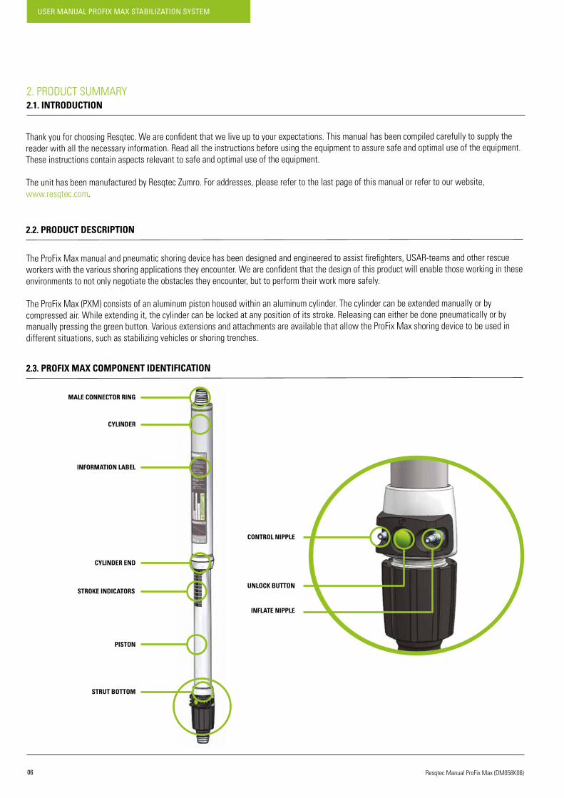
The ProFix Max (PXM) consists of an aluminum piston housed within an aluminum cylinder. The cylinder can be extended manually or by compressed air. While extending it, the cylinder can be locked at any position of its stroke. Releasing can either be done pneumatically or by manuallypressingthegreenbutton.VariousextensionsandattachmentsareavailablethatallowtheProFixMaxshoringdevicetobeusedindifferent situations, such as stabilizing vehicles or shoring trenches.
2.3. PROFIX MAX COMPONENT IDENTIFICATION
MALE CONNECTOR RING
CYLINDER
INFORMATION LABEL
CYLINDER END
STROKE INDICATORS
PISTON
STRUT BOTTOM
CONTROL NIPPLE
UNLOCK BUTTON
INFLATE NIPPLE

07
USER MANUAL PROFIX MAX STABILIZATION SYSTEM
Resqtec Manual ProFix Max (DM058K06)
2.4. HANDHELD CONTROLLER COMPONENT IDENTIFICATION
The ProFix Max handheld controller is compatible with the NT handheld controller.
2.5. PRESSURE REGULATOR COMPONENT IDENTIFICATION
INFLATE BUTTON
CONTROL BUTTON
MALE CONNECTOR
FRONT: INFLATE NIPPLES BACK: CONTROL NIPPLES
MANOMETER
FEMALE CONNECTORMALE CONNECTOR
DEPRESSURIZE BUTTON
CYLINDER PRESSURE INDICATOR WORKING PRESSURE INDICATOR
CYLINDER CONNECTOR END
CYLINDER CONNECTOR KNOB ADJUSTMENT KNOB

USER MANUAL PROFIX MAX STABILIZATION SYSTEM
08 Resqtec Manual ProFix Max (DM058K06)
3. PRODUCT RANGE3.1. PRODUCTS & ACCESSORIES
ARTICLE NUMBER ITEM DESCRIPTION PICTURE USAGE & RESTRICTIONS
8410.0290.208410.0300.208410.0310.208410.0320.208410.0330.20
PXM–470PXM – 600PXM – 880
PXM – 1400PXM-2300
See chapter 4 to 8.
8410.0500.208410.0510.208410.0520.208410.0530.208410.0540.208410.0550.20
EX – 150EX – 300EX – 600EX – 900
EX – 1200EX-1500
Seechapter7.2.
8410.0710.00REMOTE
CONTROLLER12BAR
See chapter 4.8 – 4.14.
8700.0570
NT REGULATOR 300 BARINCL.2MFIXED
INLET HOSE (MAX12BAR)
See chapter 4.8 – 4.14.
8410.0851 SET OF 2 HOSES 12BAR,10MEACH See chapter 4.8 – 4.14.
8420.0060 POWERPLATE
Mounted on Multi Swivel by using thePowerPlate plug. Also compatible with the Resqtec NT Hyrbid and CribBlock series.
ALWAYS MAKE SURE THE METAL SURFACE OF THE POWER PLATE CONNECTS WITH THE PRODUCT'S SURFACE. THE RUBBER SURFACE MUST BE FACED TOWARDS THE GROUND OR THE LOAD.
09
USER MANUAL PROFIX MAX STABILIZATION SYSTEM
Resqtec Manual ProFix Max (DM058K06)
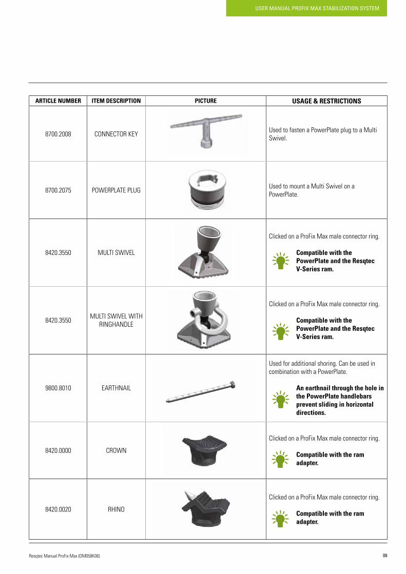
ARTICLE NUMBER ITEM DESCRIPTION PICTURE USAGE & RESTRICTIONS
8700.2008 CONNECTOR KEY Used to fasten a PowerPlate plug to a Multi Swivel.
8700.2075 POWERPLATE PLUG Used to mount a Multi Swivel on a PowerPlate.
8420.3550 MULTISWIVEL
Clicked on a ProFix Max male connector ring.
Compatible with the PowerPlate and the Resqtec V-Series ram.
8420.3550 MULTISWIVELWITHRINGHANDLE
Clicked on a ProFix Max male connector ring.
Compatible with the PowerPlate and the Resqtec V-Series ram.
9800.8010 EARTHNAIL
Used for additional shoring. Can be used in combination with a PowerPlate.
An earthnail through the hole in the PowerPlate handlebars prevent sliding in horizontal directions.
8420.0000 CROWN
Clicked on a ProFix Max male connector ring.
Compatible with the ram adapter.
8420.0020 RHINO
Clicked on a ProFix Max male connector ring.
Compatible with the ram adapter.

USER MANUAL PROFIX MAX STABILIZATION SYSTEM
10 Resqtec Manual ProFix Max (DM058K06)
ARTICLE NUMBER ITEM DESCRIPTION PICTURE USAGE & RESTRICTIONS
8420.0190 EDGE-SUPPORT
Clicked on a ProFix Max male connector ring.
Compatible with the ram adapter.
8420.0210 BEAM-SUPPORT
Clicked on a ProFix Max male connector ring.
Compatible with the ram adapter.
8420.0300 FIXEDBASE
Clicked on a ProFix Max male connector ring.
Compatible with the ram adapter.
0000.0000 CHAIN HEAD Clicked on a ProFix Max male connector ring.
8410.1500 HEAVYRESCUEMULTITOOL
Can be used as a hammer, pry, crowbar or a lever to extend or retract the ProFix Max bottom ring.
8430.0070 RAKER RAIL 1500
Used for wall, ground or ceiling support.
Compatible with the raker rail hinge.
11
USER MANUAL PROFIX MAX STABILIZATION SYSTEM
Resqtec Manual ProFix Max (DM058K06)
ARTICLE NUMBER ITEM DESCRIPTION PICTURE USAGE & RESTRICTIONS
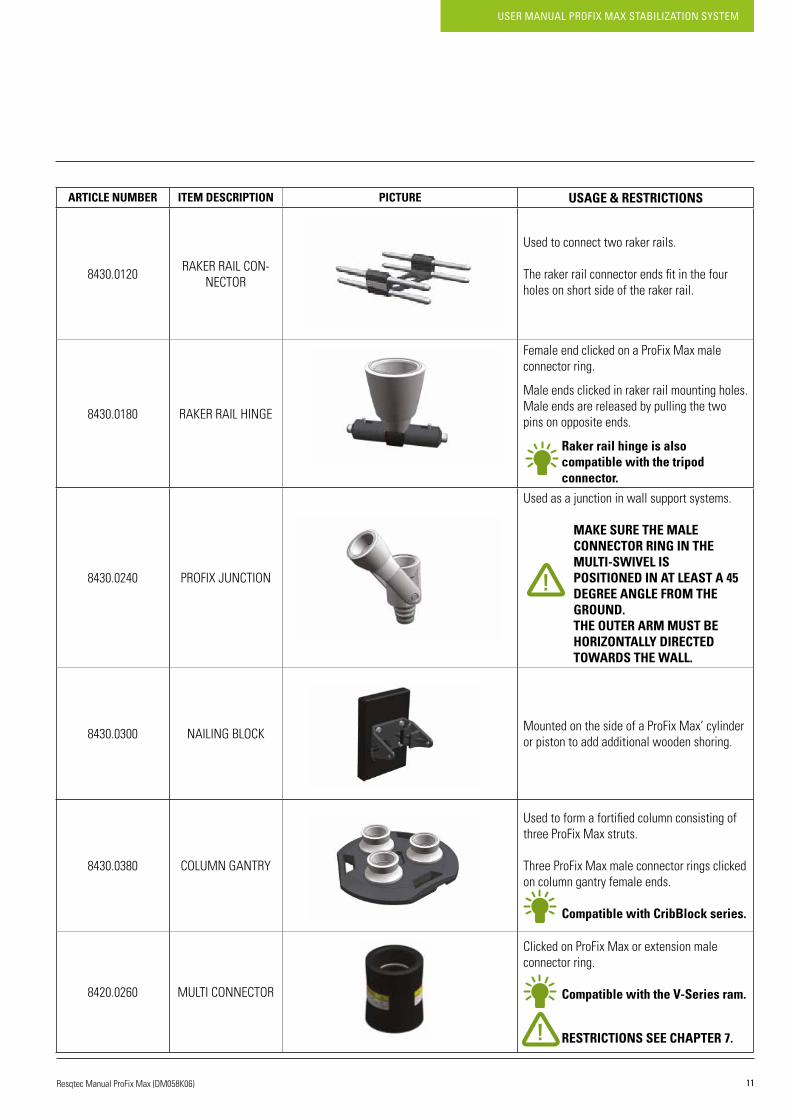
8430.0120 RAKER RAIL CON-NECTOR
Used to connect two raker rails.
Therakerrailconnectorendsfitinthefourholes on short side of the raker rail.
8430.0180 RAKER RAIL HINGE
Female end clicked on a ProFix Max male connector ring.
Male ends clicked in raker rail mounting holes.Male ends are released by pulling the two pins on opposite ends.
Raker rail hinge is also compatible with the tripod connector.
8430.0240 PROFIX JUNCTION
Used as a junction in wall support systems.
MAKE SURE THE MALE CONNECTOR RING IN THE MULTI-SWIVEL IS POSITIONED IN AT LEAST A 45 DEGREE ANGLE FROM THE GROUND. THE OUTER ARM MUST BE HORIZONTALLY DIRECTED TOWARDS THE WALL.
8430.0300 NAILINGBLOCK Mounted on the side of a ProFix Max’ cylinder or piston to add additional wooden shoring.
8430.0380 COLUMN GANTRY
Usedtoformafortifiedcolumnconsistingofthree ProFix Max struts.
Three ProFix Max male connector rings clicked on column gantry female ends.
Compatible with CribBlock series.
8420.0260 MULTI CONNECTOR
Clicked on ProFix Max or extension male connector ring.
Compatible with the V-Series ram.
RESTRICTIONS SEE CHAPTER 7.
USER MANUAL PROFIX MAX STABILIZATION SYSTEM
12 Resqtec Manual ProFix Max (DM058K06)
ARTICLE NUMBER ITEM DESCRIPTION PICTURE USAGE & RESTRICTIONS
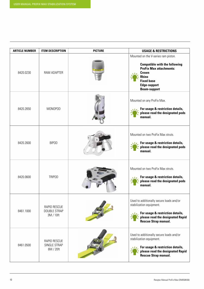
8420.0230 RAM ADAPTER
MountedontheV-seriesrampiston.
Compatible with the following ProFix Max attachments: Crown Rhino Fixed base Edge-support Beam-support
8420.2650 MONOPOD
Mounted on any ProFix Max.
For usage & restriction details, please read the designated pods manual.
8420.2600 BIPOD
Mounted on two ProFix Max struts.
For usage & restriction details, please read the designated pods manual.
8420.0600 TRIPOD
Mounted on two ProFix Max struts.
For usage & restriction details, please read the designated pods manual.
8461.1000RAPID RESCUE DOUBLESTRAP
3M / 10ft
Used to additionally secure loads and/or stabilization equipment.
For usage & restriction details, please read the designated Rapid Rescue Strap manual.
8461.0500RAPID RESCUE SINGLE STRAP
6M / 20ft
Used to additionally secure loads and/or stabilization equipment.
For usage & restriction details, please read the designated Rapid Rescue Strap manual.

13
USER MANUAL PROFIX MAX STABILIZATION SYSTEM
Resqtec Manual ProFix Max (DM058K06)
4. GENERAL OPERATING INSTRUCTIONS4.1. INITIAL USE
When receiving your equipment check for any sign of damage to the box, and report it to your supplier/distributor as damage could haveoccurred during shipping. Unpack in upright position and check the product for damage. To make sure the product conforms to yourspecifications,checktheproductdetailsonthelabelonthecylinderoftheequipment.
CHECK THE EQUIPMENT FOR EXTERNAL DAMAGE. NOTIFY THE SUPPLIER/DISTRIBUTOR IMMEDIATELY IF ANY DAMAGE IS FOUND. DO NOT USE DAMAGED EQUIPMENT UNDER ANY CIRCUMSTANCE!
In general different types of operations can be distinguished:• Operating the locking device• Operating the ProFix Max• (Dis)connecting an attachment• (Dis)connecting a PowerPlate• Using the ProFix Max bottom ring• Connecting pneumatic hoses• Disconnecting pneumatic hoses• Connecting the pressure regulator• Disconnecting the pressure regulator• Pneumatically follow a load moving upwards• Pneumatically follow a load moving downwards• Depressurizing the ProFix Max
4.2. PREPARATION BEFORE USE
• Check the ProFix Max’s cylinder and piston. Do not use if they exhibit major damage and/or do not function as intended. • See chapter 6 for further information.
• Check the operation of the unlock button. When extended, the ProFix Max should retract smoothly when the button is pushed. • See chapter 6 for further information.
USER MANUAL PROFIX MAX STABILIZATION SYSTEM
14 Resqtec Manual ProFix Max (DM058K06)
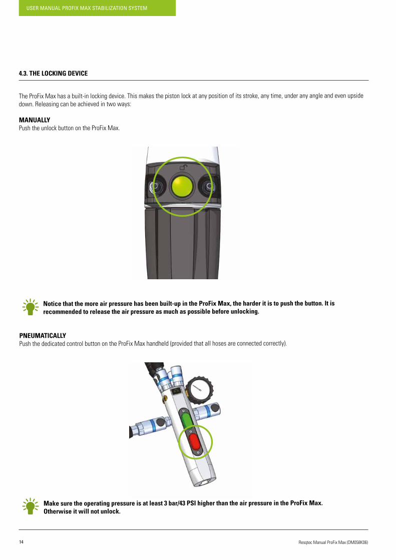
4.3. THE LOCKING DEVICE
TheProFixMaxhasabuilt-inlockingdevice.Thismakesthepistonlockatanypositionofitsstroke,anytime,underanyangleandevenupsidedown. Releasing can be achieved in two ways:
MANUALLYPush the unlock button on the ProFix Max.
Notice that the more air pressure has been built-up in the ProFix Max, the harder it is to push the button. It is recommended to release the air pressure as much as possible before unlocking.
PNEUMATICALLYPush the dedicated control button on the ProFix Max handheld (provided that all hoses are connected correctly).
Make sure the operating pressure is at least 3 bar/43 PSI higher than the air pressure in the ProFix Max. Otherwise it will not unlock.

15
USER MANUAL PROFIX MAX STABILIZATION SYSTEM
Resqtec Manual ProFix Max (DM058K06)
4.4. OPERATING THE PROFIX MAX
EXTENDING MANUALLY
TousetheProfixmaxpneumatically,pleaseseechapter4.8to4.14.
RETRACTING MANUALLY
WHILE RETRACTING THE PROFIX MAX, MAKE SURE THAT HANDS OR FINGERS DO NOT GET STUCK BETWEEN THE CYLINDER AND THE PISTON. THIS MAY CAUSE MINOR INJURIES.
TousetheProfixMaxpneumatically,pleaseseechapter4.8to4.14.
The ProFix Max now extends.
The ProFix Max now retracts.
The ProFix Max only retracts when it is not supporting any load.
Hold the ProFix Max by its cylinder. Pull the cylinder upwards.
Hold the ProFix Max by its cylinder. Push the unlock button.
1
1
2
2
USER MANUAL PROFIX MAX STABILIZATION SYSTEM
16 Resqtec Manual ProFix Max (DM058K06)
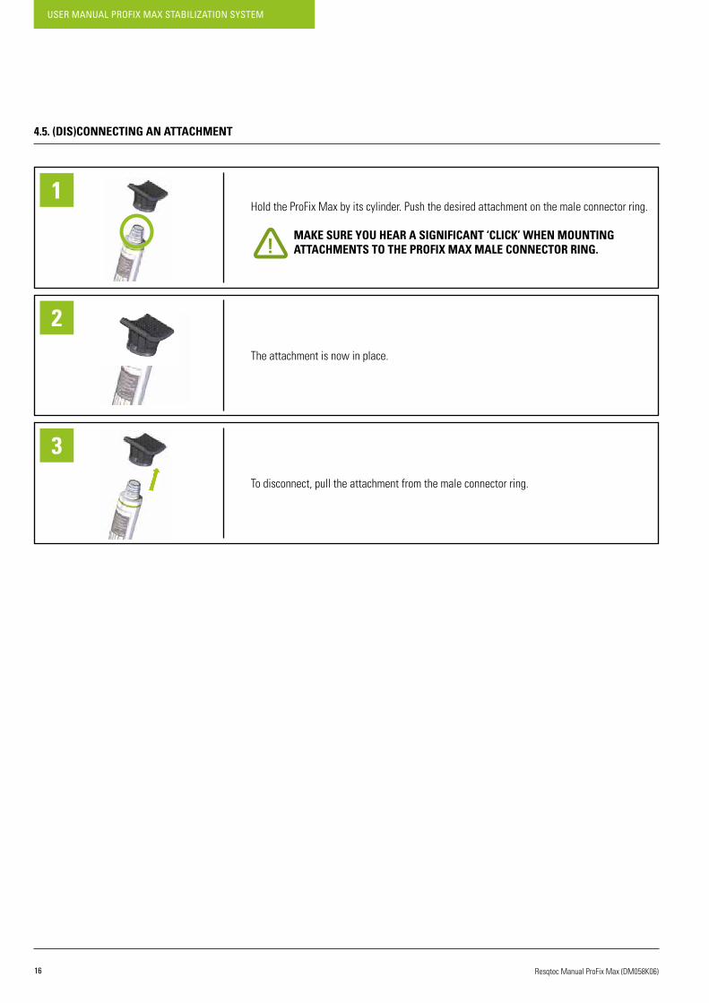
4.5. (DIS)CONNECTING AN ATTACHMENT
Hold the ProFix Max by its cylinder. Push the desired attachment on the male connector ring.
MAKE SURE YOU HEAR A SIGNIFICANT ‘CLICK’ WHEN MOUNTING ATTACHMENTS TO THE PROFIX MAX MALE CONNECTOR RING.
The attachment is now in place.
To disconnect, pull the attachment from the male connector ring.
1
2
3
17
USER MANUAL PROFIX MAX STABILIZATION SYSTEM
Resqtec Manual ProFix Max (DM058K06)
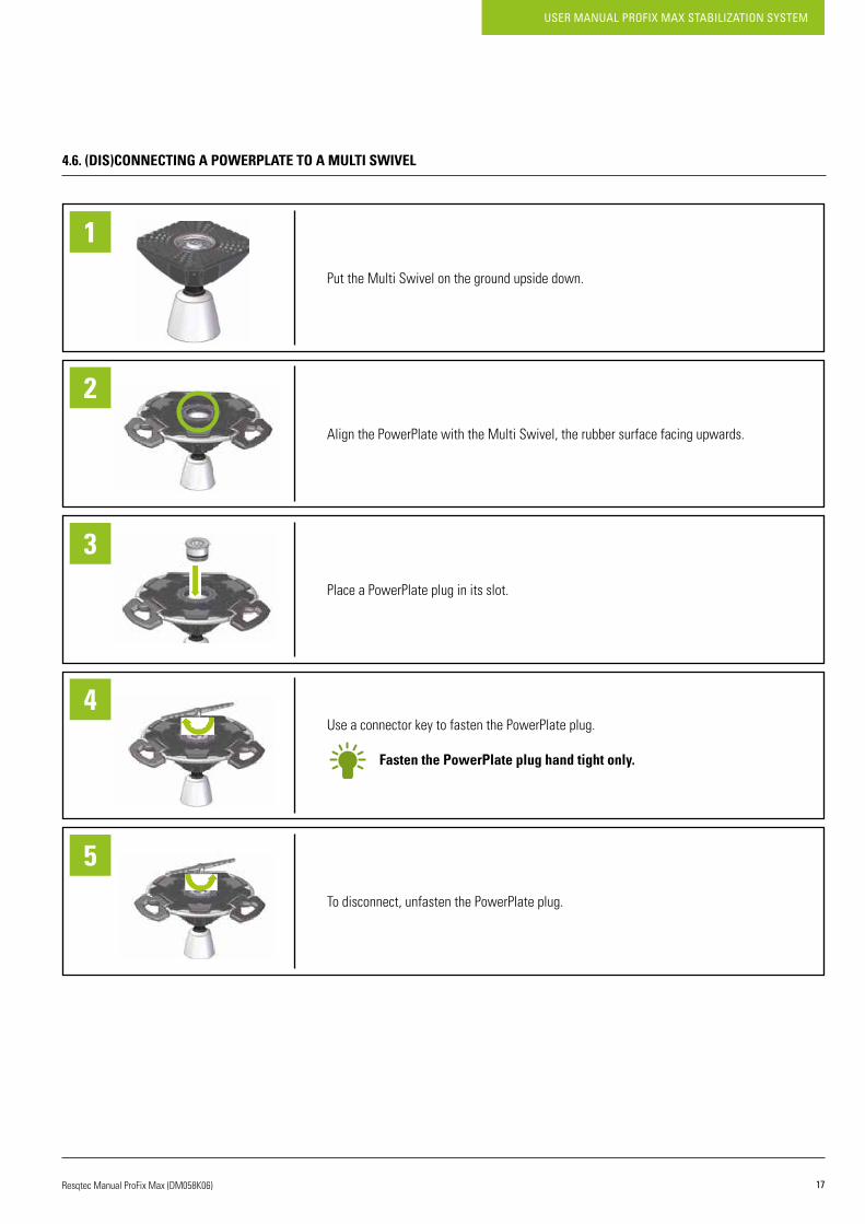
4.6. (DIS)CONNECTING A POWERPLATE TO A MULTI SWIVEL
Put the Multi Swivel on the ground upside down.
Align the PowerPlate with the Multi Swivel, the rubber surface facing upwards.
Place a PowerPlate plug in its slot.
Use a connector key to fasten the PowerPlate plug.
Fasten the PowerPlate plug hand tight only.
To disconnect, unfasten the PowerPlate plug.
1
2
3
4
5
USER MANUAL PROFIX MAX STABILIZATION SYSTEM
18 Resqtec Manual ProFix Max (DM058K06)
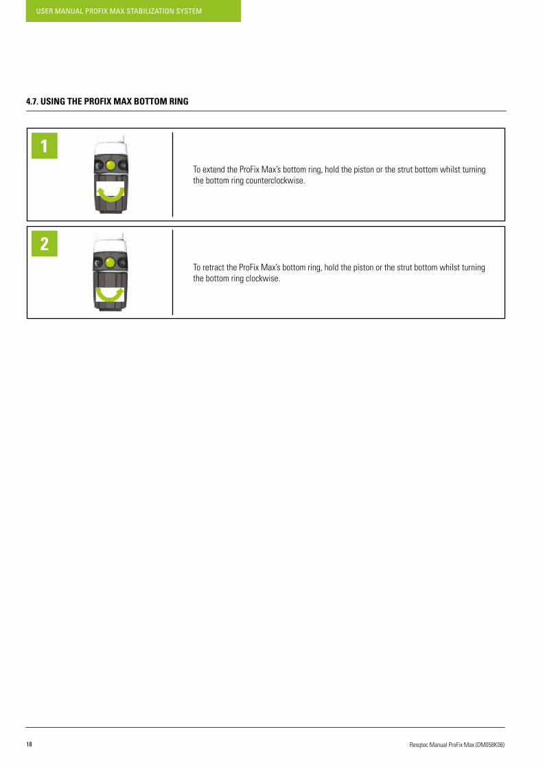
4.7. USING THE PROFIX MAX BOTTOM RING
To extend the ProFix Max’s bottom ring, hold the piston or the strut bottom whilst turning the bottom ring counterclockwise.
To retract the ProFix Max’s bottom ring, hold the piston or the strut bottom whilst turning the bottom ring clockwise.
1
2
19
USER MANUAL PROFIX MAX STABILIZATION SYSTEM
Resqtec Manual ProFix Max (DM058K06)
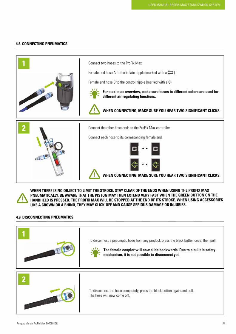
4.8.CONNECTINGPNEUMATICS
WHEN THERE IS NO OBJECT TO LIMIT THE STROKE, STAY CLEAR OF THE ENDS WHEN USING THE PROFIX MAX PNEUMATICALLY. BE AWARE THAT THE PISTON MAY THEN EXTEND VERY FAST WHEN THE GREEN BUTTON ON THE HANDHELD IS PRESSED. THE PROFIX MAX WILL BE STOPPED AT THE END OF ITS STROKE. WHEN USING ACCESSORIES LIKE A CROWN OR A RHINO, THEY MAY CLICK-OFF AND CAUSE SERIOUS DAMAGE OR INJURIES.
4.9. DISCONNECTING PNEUMATICS
Connect two hoses to the ProFix Max:
FemaleendhoseAtotheinflatenipple(markedwitha)
FemaleendhoseBtothecontrolnipple(markedwithaC)
For maximum overview, make sure hoses in different colors are used for different air regulating functions.
WHEN CONNECTING, MAKE SURE YOU HEAR TWO SIGNIFICANT CLICKS.
Connect the other hose ends to the ProFix Max controller.
Connect each hose to its corresponding female end.
WHEN CONNECTING, MAKE SURE YOU HEAR TWO SIGNIFICANT CLICKS.
1
2
To disconnect a pneumatic hose from any product, press the black button once, then pull.
The female coupler will now slide backwards. Due to a built in safety mechanism, it is not possible to disconnect yet.
To disconnect the hose completely, press the black button again and pull. The hose will now come off.
1
2

USER MANUAL PROFIX MAX STABILIZATION SYSTEM
20 Resqtec Manual ProFix Max (DM058K06)
4.10. CONNECTING THE PRESSURE REGULATOR
If applicable: unfasten the safety bolt from the air cylinder.
Fasten the regulator to the air cylinder.
Fasten hand tight only.
Connect the regulator’s hose to the handheld controller(s).
TWO CLICKS SHOULD BE HEARD WHEN CONNECTING THE HOSE.
The ProFix Max and the NT-Hybrid handheld controllers are connectable.
Open the air cylinder’s valve to pressurize the pressure regulator.
Connect the handheld controller before opening the cylinder, to avoid losing air.
Use the adjustment knob of the regulator to regulate the working pressure and topressurize the handheld controller(s).
SETTHEWORKINGPRESSUREBETWEEN8AND12BARS/116AND 174 PSI.
1
2
3
4
5
6
BEFORE CONNECTING THE REGULATOR, MAKE SURE THE AIR CYLINDER’S VALVE IS FULLY CLOSED.

21
USER MANUAL PROFIX MAX STABILIZATION SYSTEM
Resqtec Manual ProFix Max (DM058K06)
4.11. DISCONNECTING THE PRESSURE REGULATOR
Turn the adjustment knob counter clockwise (completely) to release the working pressure.
If excess pressure remains in the pressure regulator, turn the adjustment knob clockwise (completely) and then counter clockwise (completely) again.
Dismount the regulator from the air cylinder.
Close the air bottle with the safety bolt.
For connecting a new air cylinder, please see chapter 4.10.
1
2
3
4
5
6
BEFORE DISCONNECTING THE REGULATOR, MAKE SURE THE AIR CYLINDER’S VALVE IS FULLY CLOSED.
USER MANUAL PROFIX MAX STABILIZATION SYSTEM
22 Resqtec Manual ProFix Max (DM058K06)
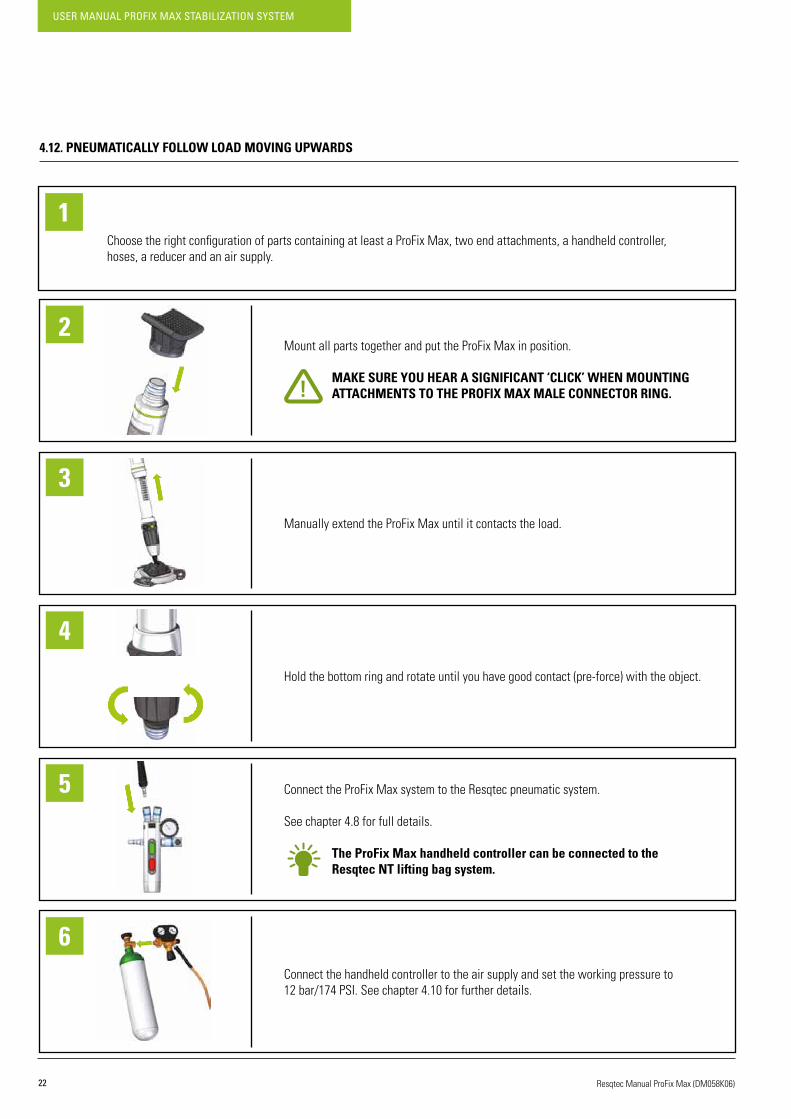
4.12. PNEUMATICALLY FOLLOW LOAD MOVING UPWARDS
ChoosetherightconfigurationofpartscontainingatleastaProFixMax,twoendattachments,ahandheldcontroller,hoses, a reducer and an air supply.
1
Mount all parts together and put the ProFix Max in position.
MAKE SURE YOU HEAR A SIGNIFICANT ‘CLICK’ WHEN MOUNTING ATTACHMENTS TO THE PROFIX MAX MALE CONNECTOR RING.
Manually extend the ProFix Max until it contacts the load.
Holdthebottomringandrotateuntilyouhavegoodcontact(pre-force)withtheobject.
Connect the ProFix Max system to the Resqtec pneumatic system.
See chapter 4.8 for full details.
The ProFix Max handheld controller can be connected to the Resqtec NT lifting bag system.
Connect the handheld controller to the air supply and set the working pressure to 12bar/174PSI.Seechapter4.10forfurtherdetails.
2
3
4
5
6
23
USER MANUAL PROFIX MAX STABILIZATION SYSTEM
Resqtec Manual ProFix Max (DM058K06)
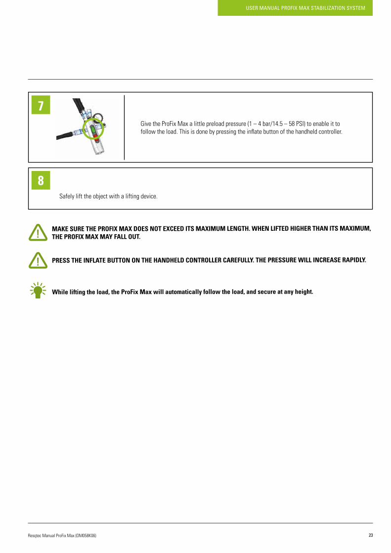
MAKE SURE THE PROFIX MAX DOES NOT EXCEED ITS MAXIMUM LENGTH. WHEN LIFTED HIGHER THAN ITS MAXIMUM, THE PROFIX MAX MAY FALL OUT.
PRESS THE INFLATE BUTTON ON THE HANDHELD CONTROLLER CAREFULLY. THE PRESSURE WILL INCREASE RAPIDLY.
While lifting the load, the ProFix Max will automatically follow the load, and secure at any height.
Give the ProFix Max a little preload pressure (1 – 4 bar/14.5 – 58 PSI) to enable it to followtheload.Thisisdonebypressingtheinflatebuttonofthehandheldcontroller.
Safely lift the object with a lifting device.
7
8

USER MANUAL PROFIX MAX STABILIZATION SYSTEM
24 Resqtec Manual ProFix Max (DM058K06)
4.13. PNEUMATICALLY FOLLOW LOAD MOVING DOWNWARDS
If disconnected, connect the ProFix Max system to the Resqtec pneumatic system according to chapter 4.8 & 4.10.
The ProFix Max handheld controller can be connected to the NT handheld controller.
Lift the load slightly until the ProFix Max extends.
Keep pressing the control button to continue.
The ProFix Max is designed in such a way that it can only be retracted when it is not supporting any weight. Make sure that the entire weight is supported by your lifting device, so ProFix Max can unlock and retract securely.
RELEASE THE CONTROL BUTTON IF ANYTHING GOES WRONG OR TO STOP LOWERING.
Start lowering the load with your lifting device. The ProFix Max now retracts and follows the load downwards.
Keep pressing the control button to continue lowering.
RELEASE THE CONTROL BUTTON IF ANYTHING GOES WRONG OR TO STOP LOWERING.
1
Give the ProFix Max a little preload pressure (1 – 4 bar/14.5 – 58 PSI) to enable it to followtheload.Thisisdonebypressingtheinflatebuttonofthehandheldcontroller.
Press the control button and keep it pressed in.
RELEASE THE CONTROL BUTTON IF ANYTHING GOES WRONG OR TO STOP LOWERING.
2
3
4
5

25
USER MANUAL PROFIX MAX STABILIZATION SYSTEM
Resqtec Manual ProFix Max (DM058K06)
WHEN THE PROFIX MAX REACHES DEFAULT POSITION, IT WILL STOP RETRACTING AND TAKE OVER THE LOAD.
By releasing the red button the system is blocked immediately.
4.14. DEPRESSURIZING THE PROFIX MAX
Keep on pressing the control button until the load has returned in the required position.
RELEASE THE RED BUTTON IF ANYTHING GOES WRONG OR TO STOP LOWERING.
Press the control button and keep it pressed in.
Simultaneously press the black depressurizing button on the back and keep it pressed in.
ProFixMaxdeflates&retracts.
PROFIX MAX MAY RETRACT FASTER THAN EXPECTED. MAKE SURE TO EITHER HOLD IT TO PREVENT IT FROM FALLING, OR LET IT REST ON THE GROUND HORIZONTALLY.
6
1
2
3
USER MANUAL PROFIX MAX STABILIZATION SYSTEM
26 Resqtec Manual ProFix Max (DM058K06)
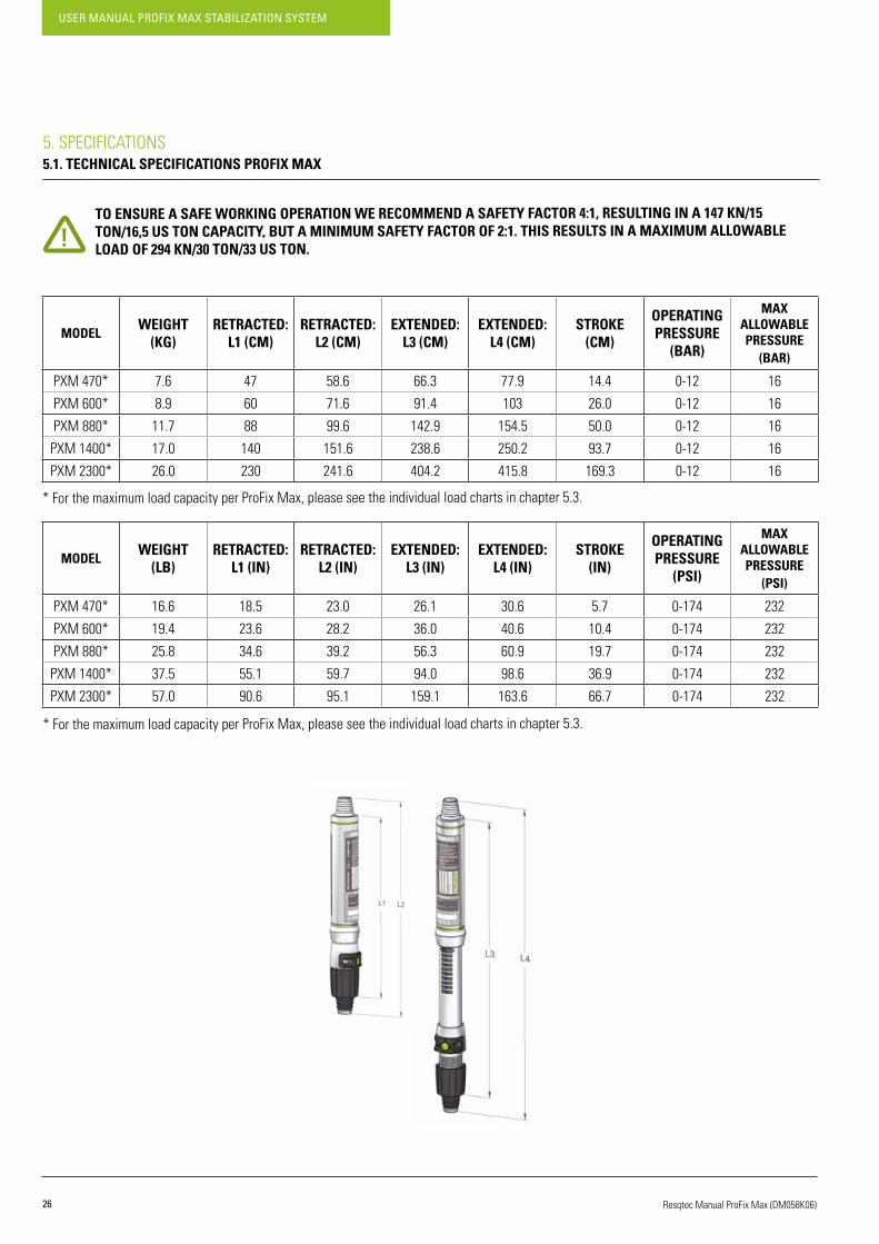
5. SPECIFICATIONS5.1. TECHNICAL SPECIFICATIONS PROFIX MAX
TO ENSURE A SAFE WORKING OPERATION WE RECOMMEND A SAFETY FACTOR 4:1, RESULTING IN A 147 KN/15 TON/16,5 US TON CAPACITY, BUT A MINIMUM SAFETY FACTOR OF 2:1. THIS RESULTS IN A MAXIMUM ALLOWABLE LOAD OF 294 KN/30 TON/33 US TON.
* For the maximum load capacity per ProFix Max, please see the individual load charts in chapter 5.3.
* For the maximum load capacity per ProFix Max, please see the individual load charts in chapter 5.3.
MODELWEIGHT
(KG)RETRACTED:
L1 (CM)RETRACTED:
L2 (CM)EXTENDED:
L3 (CM)EXTENDED:
L4 (CM)STROKE
(CM)
OPERATING PRESSURE
(BAR)
MAXALLOWABLEPRESSURE
(BAR)
PXM470* 7.6 47 58.6 66.3 77.9 14.4 0-12 16
PXM 600* 8.9 60 71.6 91.4 103 26.0 0-12 16
PXM 880* 11.7 88 99.6 142.9 154.5 50.0 0-12 16
PXM 1400* 17.0 140 151.6 238.6 250.2 93.7 0-12 16
PXM 2300* 26.0 230 241.6 404.2 415.8 169.3 0-12 16
MODELWEIGHT
(LB)RETRACTED:
L1 (IN)RETRACTED:
L2 (IN)EXTENDED:
L3 (IN)EXTENDED:
L4 (IN)STROKE
(IN)
OPERATING PRESSURE
(PSI)
MAXALLOWABLEPRESSURE
(PSI)
PXM470* 16.6 18.5 23.0 26.1 30.6 5.7 0-174 232
PXM 600* 19.4 23.6 28.2 36.0 40.6 10.4 0-174 232
PXM 880* 25.8 34.6 39.2 56.3 60.9 19.7 0-174 232
PXM 1400* 37.5 55.1 59.7 94.0 98.6 36.9 0-174 232
PXM 2300* 57.0 90.6 95.1 159.1 163.6 66.7 0-174 232

27
USER MANUAL PROFIX MAX STABILIZATION SYSTEM
Resqtec Manual ProFix Max (DM058K06)
5.2. TECHNICAL SPECIFICATIONS EXTENSIONS
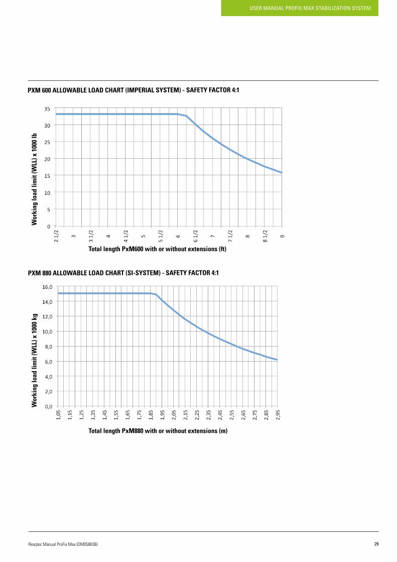
5.3. LOAD CHARTS PROFIX MAX
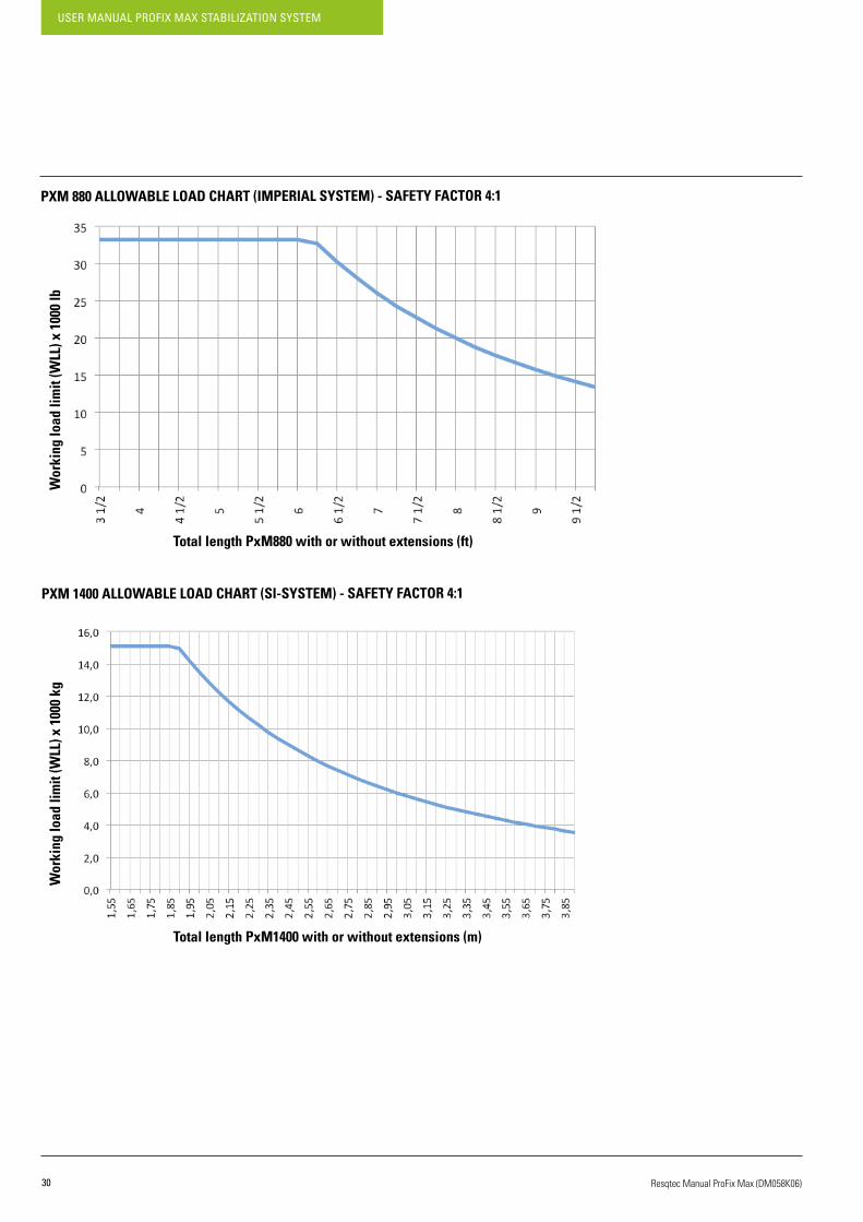
On the next page the load charts for the ProFix Max with and without extensions are shown.Adding extensions reduces the working load of a ProFix Max shoring device, depending of the length of extensions and the length of the ProFix Max.
Note: the non-horizontal line indicates the area where buckling is the limiting failure mode.
PXM 470 ALLOWABLE LOAD CHART (SI-SYSTEM) - SAFETY FACTOR 4:1
MODEL WEIGHT (KG) LENGTH (CM)WORKING LOAD LIMIT
(KN/TON)
EX 150 1.8 15.3 147/15
EX 300 2.5 30.3 147/15
EX 600 4.1 60.3 147/15
EX 900 5.6 90.3 147/15
EX 1200 7.2 120.3 147/15
EX 1500 8.8 150.3 147/15
MODEL WEIGHT (LB) LENGTH (IN) WORKING LOAD LIMIT(US TON)
EX 150 3.9 6 16.5
EX 300 5.5 12 16.5
EX 600 9 23.7 16.5
EX 900 12.2 35.6 16.5
EX 1200 15.9 47.4 16.5
EX 1500 19.3 59.2 16.5
Total length PxM470 with or without extensions (m)
Wor
king
load
lim
it (W
LL) x
100
0 kg

USER MANUAL PROFIX MAX STABILIZATION SYSTEM
28 Resqtec Manual ProFix Max (DM058K06)
PXM 470 ALLOWABLE LOAD CHART (IMPERIAL SYSTEM) - SAFETY FACTOR 4:1
PXM 600 ALLOWABLE LOAD CHART (SI-SYSTEM) - SAFETY FACTOR 4:1
Total length PxM470 with or without extensions (ft)
Total length PxM600 with or without extensions (m)
Wor
king
load
lim
it (W
LL) x
100
0 lb
Wor
king
load
lim
it (W
LL) x
100
0 kg
29
USER MANUAL PROFIX MAX STABILIZATION SYSTEM
Resqtec Manual ProFix Max (DM058K06)
PXM 600 ALLOWABLE LOAD CHART (IMPERIAL SYSTEM) - SAFETY FACTOR 4:1
PXM880ALLOWABLELOADCHART(SI-SYSTEM)-SAFETYFACTOR4:1
Total length PxM600 with or without extensions (ft)
TotallengthPxM880withorwithoutextensions(m)
Wor
king
load
lim
it (W
LL) x
100
0 lb
Wor
king
load
lim
it (W
LL) x
100
0 kg
USER MANUAL PROFIX MAX STABILIZATION SYSTEM
30 Resqtec Manual ProFix Max (DM058K06)
PXM880ALLOWABLELOADCHART(IMPERIALSYSTEM)-SAFETYFACTOR4:1
PXM 1400 ALLOWABLE LOAD CHART (SI-SYSTEM) - SAFETY FACTOR 4:1
TotallengthPxM880withorwithoutextensions(ft)
Total length PxM1400 with or without extensions (m)
Wor
king
load
lim
it (W
LL) x
100
0 lb
Wor
king
load
lim
it (W
LL) x
100
0 kg

31
USER MANUAL PROFIX MAX STABILIZATION SYSTEM
Resqtec Manual ProFix Max (DM058K06)
PXM 1400 ALLOWABLE LOAD CHART (IMPERIAL SYSTEM) - SAFETY FACTOR 4:1
PXM 2300 ALLOWABLE LOAD CHART (SI-SYSTEM) - SAFETY FACTOR 4:1
Total length PxM1400 with or without extensions (ft)
Total length PxM2300 with or without extensions (m)
Wor
king
load
lim
it (W
LL) x
100
0 lb
Wor
king
load
lim
it (W
LL) x
100
0 kg

USER MANUAL PROFIX MAX STABILIZATION SYSTEM
32 Resqtec Manual ProFix Max (DM058K06)
PXM 2300 ALLOWABLE LOAD CHART (IMPERIAL SYSTEM) - SAFETY FACTOR 4:1
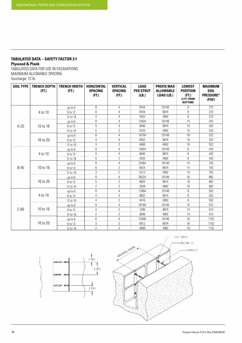
5.4. TABULATED DATA – TRENCHES AND/OR EXCAVATIONS
As part of the United States Department of Labor, the Occupational Health and Safety Administration (OSHA) assures safe and healthful working conditions for working men and women, by setting and enforcing standards.
Based on the OSHA enforcing standards, the following tabulated data is given to assure safe working conditions while shoring trenches.
Total length PxM2300 with or without extensions (ft)
Wor
king
load
lim
it (W
LL) x
100
0 lb

33
USER MANUAL PROFIX MAX STABILIZATION SYSTEM
Resqtec Manual ProFix Max (DM058K06)
TABULATED DATA – SAFETY FACTOR 4:1Plywood & PlankTABULATEDDATAFORUSEINEXCAVATIONSMAXIMUMALLOWABLESPACINGSurcharge:72lb.
SOIL TYPE
A-25
B-45
C-60
TRENCH DEPTH(FT.)
4 to 10
10 to 16
16 to 20
4 to 10
10 to 16
16 to 20
4 to 10
10 to 16
16 to 20
HORIZONTALSPACING
(FT.)
VERTICALSPACING
(FT.)
LOADPER STRUT
(LB.)
PROFIX MAXALLOWABLE LOAD (LB.)
LOWEST POSITION
(FT.)(2 FT. FROM BOTTOM)
MAXIMUMSOIL
PRESSURE*(PSF)
884855843855863852844842632
TRENCH WIDTH (FT.)
up to 66 to 12
12 to 16up to 66 to 12
12 to 16up to 66 to 12
12 to 16up to 66 to 12
12 to 16up to 66 to 12
12 to 16up to 66 to 12
12 to 16up to 66 to 12
12 to 16up to 66 to 12
12 to 16up to 66 to 12
12 to 16
444442443442422422442422422
870487044352
13504844042201670483524698
1382486404320
2246484244212
28224882035281766488324416
29184729636482764869124608
3314888744992
3314888744992
3314888744992
3314888744992
3314888744992
3314888744992
3314888744992
3314888744992
3314888744992
888
141414181818888
141414181818888
141414181818
272272272422422422522522522432432432702702702882882882552552552912912912
115211521152
USER MANUAL PROFIX MAX STABILIZATION SYSTEM
34 Resqtec Manual ProFix Max (DM058K06)
TABULATED DATA – SAFETY FACTOR 3:1Plywood & PlankTABULATEDDATAFORUSEINEXCAVATIONSMAXIMUMALLOWABLESPACINGSurcharge:72lb.
SOIL TYPE
A-25
B-45
C-60
TRENCH DEPTH(FT.)
4 to 10
10 to 16
16 to 20
4 to 10
10 to 16
16 to 20
4 to 10
10 to 16
16 to 20
HORIZONTALSPACING
(FT.)
VERTICALSPACING
(FT.)
LOADPER STRUT
(LB.)
PROFIX MAXALLOWABLE LOAD (LB.)
LOWEST POSITION
(FT.)(2 FT. FROM BOTTOM)
MAXIMUMSOIL
PRESSURE*(PSF)
884855843855863852844842632
TRENCH WIDTH (FT.)
up to 66 to 12
12 to 16up to 66 to 12
12 to 16up to 66 to 12
12 to 16up to 66 to 12
12 to 16up to 66 to 12
12 to 16up to 66 to 12
12 to 16up to 66 to 12
12 to 16up to 66 to 12
12 to 16up to 66 to 12
12 to 16
444442443442422422442422422
870487044352
13504844042201670483524698
1382486404320
2246484244212
28224882035281766488324416
29184729636482764869124608
3314888744992
3314888744992
3314888744992
3314888744992
3314888744992
3314888744992
3314888744992
3314888744992
3314888744992
888
141414181818888
141414181818888
141414181818
272272272422422422522522522432432432702702702882882882552552552912912912
115211521152

35
USER MANUAL PROFIX MAX STABILIZATION SYSTEM
Resqtec Manual ProFix Max (DM058K06)
TABULATED DATA – SAFETY FACTOR 2:1Plywood & PlankTABULATEDDATAFORUSEINEXCAVATIONSMAXIMUMALLOWABLESPACINGSurcharge:72lb.
SOIL TYPE
A-25
B-45
C-60
TRENCH DEPTH(FT.)
4 to 10
10 to 16
16 to 20
4 to 10
10 to 16
16 to 20
4 to 10
10 to 16
16 to 20
HORIZONTALSPACING
(FT.)
VERTICALSPACING
(FT.)
LOADPER STRUT
(LB.)
PROFIX MAXALLOWABLE LOAD (LB.)
LOWEST POSITION
(FT.)(2 FT. FROM BOTTOM)
MAXIMUMSOIL
PRESSURE*(PSF)
888885886885864853886843853
TRENCH WIDTH (FT.)
up to 66 to 12
12 to 16up to 66 to 12
12 to 16up to 66 to 12
12 to 16up to 66 to 12
12 to 16up to 66 to 12
12 to 16up to 66 to 12
12 to 16up to 66 to 12
12 to 16up to 66 to 12
12 to 16up to 66 to 12
12 to 16
444444443444443443443443432
870487048704
1350413504844016704167049396
13824138248640
22464168488424
2822417640793817664176649936
29184145928208
36864172806912
66296177499984
66296177499984
66296177499984
66296177499984
66296177499984
66296177499984
66296177499984
66296177499984
66296177499984
888
141414181818888
141414181818888
141414181818
272272272422422422522522522432432432702702702882882882552552552912912912
115211521152

USER MANUAL PROFIX MAX STABILIZATION SYSTEM
36 Resqtec Manual ProFix Max (DM058K06)
6. MAINTENANCE & STORAGE6.1. MAINTENANCE AFTER USE
Generally speaking it is most important to keep your equipment clean. Clean equipment will not wear down as fast; hence a longer service life can be achieved.
ACTION EXPLANATION ADDITIONAL INFORMATION
1. Clean and dry the ProFix Max and accessories used before storage.
• Preferably use dry, clean paper cloth.
• Mild soapy water can be used if necessary.
Do NOT use any oil.
Dry thoroughly after using water.
2. Check the product for any damage,especially scratches on the piston.
•Visuallycheckfordamage. If structural damage to the product isdiscovered, contact your Resqtec dealer.
3. Clean and check the attachments for any damage.
•Visuallycheckfordamage.
• Use cloth or steel brush to clean.
• Check if the internal spring of the ProFix Max heads is still in position and check for any signs of damage.
Do NOT use any oil.
4. Check the nipples on the ProFix Max for dirt. • Use dry, paper cloth.
Do NOT use any oil.
5. When used, clean and check the hoses and connectors for any damage.
•Visuallycheckfordamage.
• Use compressed air to clean the connectors.
• Clean the hoses with mild soapy water.
If structural damage to the hosesand/or connectors is discovered, contact your Resqtec dealer.
Dry thoroughly after using water.
6.
Let the ProFix Max extend and retract a few times. Make sure to hear no strange sounds and to feel no resistance while extending or retracting.
• Possible strange sounds: screaking, scratching or bubbling.
If strange sounds can be heard, or if anything does not operate well, contact your Resqtec dealer.

37
USER MANUAL PROFIX MAX STABILIZATION SYSTEM
Resqtec Manual ProFix Max (DM058K06)
6.2. REGULAR MAINTENANCE
It is advisable to carry out regular maintenance; depending on the use at least every 3 months or 25 operating hours.
When carrying out regular maintenance one should, in addition to the steps described in chapter 6.1, pay extra attention to the following:
ACTION EXPLANATION ADDITIONAL INFORMATION
1. Check the product for any damage,especially scratches on the piston. •Visuallycheckfordamage. If structural damage to the product is
discovered, contact your Resqtec dealer.
2. Check the attachments for any damage.
•Visuallycheckfordamage.
• Check if the internal spring of the ProFix Max heads is still in position and check for any signs of damage.
Do NOT use any oil.
3. ChecktheinflateandcontrolnipplesontheProFix Max for any damage • Use dry, paper cloth. Do NOT use any oil.
4. Check the hoses and connectors for any damage.
•Visuallycheckfordamage.
• Use compressed air to clean the connectors.
If structural damage to the hosesand/or connectors is discovered, contact your Resqtec dealer.
Dry thoroughly after using water.
5.
Let the ProFix Max extend and retract a few times. Make sure to hear no strange sounds and to feel no resistance while extending or retracting.
• Possible strange sounds: screaking, scratching or bubbling. If strange sounds can be heard, or if
anything does not operate well,contact your Resqtec dealer.
USER MANUAL PROFIX MAX STABILIZATION SYSTEM
38 Resqtec Manual ProFix Max (DM058K06)
6.3. ANNUAL MAINTENANCE
Many years of safe use is guaranteed if the product is properly cared for and maintained. To this end the product must be inspected at least once a year. This must be carried out by a service technician trained by Resqtec who possesses the necessary tools and testing equipment.
It is also possible for you, the user, to carry out maintenance yourself. In the context of your own safety and the product liability it is necessary thatappropriatetrainingshouldbeundertakenfirst.Yoursuppliercanadviseyouonthisand/orattendtotheannualmaintenanceonacontractbasis, if desired.
STRUCTURALLY DAMAGED AND/OR BROKEN EQUIPMENT MUST NEVER BE USED DURING RESCUE OPERATIONS. THIS MAY RESULT IN VERY DANGEROUS AND POTENTIALLY HARMFUL SITUATIONS. DO NOT ATTEMPT!
If structural damage and/or broken equipment or parts are discovered, immediately contact your distributor/supplier or the manufacturer.
DO NOT REPAIR ANY BROKEN EQUIPMENT AND/OR PARTS. ALWAYS CONTACT YOUR DISTRIBUTOR/SUPPLIER OR THE MANUFACTURER.
Repairing equipment and/or parts causes your warranty to expire. Always contact your distributor/supplier or the manufacturer when broken partsand/orequipmentarediscovered.Brokenequipmentand/orpartscanthenbesenttocertifiedservicecenters.
6.4. RECOMMENDED STORAGE
The following storage recommendations count for the ProFix Max and its accessories:• Completely depressurize and retract the ProFix Max.• Store out of direct sunlight•Storetheequipmentinadry,well-ventilatedarea:
Recommended storage temperature range 10˚C–30˚C/50°F-86°F
Recommended storage relative humidity 0 – 60%

39
USER MANUAL PROFIX MAX STABILIZATION SYSTEM
Resqtec Manual ProFix Max (DM058K06)
7.WARNINGS&LIMITATIONS7.1. GENERAL INSTRUCTIONS
WHEN CLICKING EQUIPMENT TOGETHER MAKE SURE TO HEAR AND FEEL A SIGNIFICANT CLICK. SEE THAT THE PARTS ARE WELL CONNECTED AND THAT THERE IS NO GAP BETWEEN THE CONNECTED SURFACES.
7.2. EXTENSIONS
ExtensionscanbeclickedonBOTHSIDESoftheProFixMax,aslongasthefollowingrules&restrictionsareconsidered:
USING EXTENSIONS IS ALLOWED TO: • A MAXIMUM LENGTH OF 1.2m/47 1/4” AND • A MAXIMUM OF 2 EXTENSIONS
IGNORING THESE RESTRICTIONS WILL CREATE DANGEROUS AND POTENTIALLY HARMFUL SITUATIONS! DO NOT ATTEMPT!
The following extensions are available to extend the length of the struts:
ProFix Max +2 Extensions <1.2m/471/4"(any sequence)
>1.2m/471/4"(any sequence)
More than 2extensions
(any sequence)
TYPE LENGTH (MM) REMARKS
EX 150 151
EX 300 301
EX 600 601
EX 900 901
EX 1200 1201
EX 1500 1501 ONLY TO BE USED IN COMBINATION WITH PROFIX MAX 470 & PROFIX MAX 600

USER MANUAL PROFIX MAX STABILIZATION SYSTEM
40 Resqtec Manual ProFix Max (DM058K06)
EX150
+
EX300
+
EX600
+
EX150
EX300
EX600
EX900
EX1200(COMBININGNOTALLOWED:>1.2M/471/4")
EX1500(NOTALLOWED:>1.2M/471/4")
EX150
EX300
EX600
EX900
EX1200(COMBININGNOTALLOWED:>1.2M/471/4")
EX1500(NOTALLOWED:>1.2M/471/4")
EX150
EX300
EX600
EX900(COMBININGNOTALLOWED:>1.2M/471/4")
EX1200(NOTALLOWED:>1.2M/471/4")
EX1500(NOTALLOWED:>1.2M/471/4")

41
USER MANUAL PROFIX MAX STABILIZATION SYSTEM
Resqtec Manual ProFix Max (DM058K06)
EX1500 MAY ONLY BE USED IN COMBINATION WITH PROFIX MAX 470 & PROFIX MAX 600
USING EXTENSIONS IS ALLOWED TO: • A MAXIMUM LENGTH OF 1.2m / 47 1/4" AND • A MAXIMUM OF 2 EXTENSIONS
EX900
EX1200
EX1500
EX150
EX300
EX600(COMBININGNOTALLOWED:>1.2M/471/4")
EX900(NOTALLOWED:>1.2M/471/4")
EX1200(NOTALLOWED:>1.2M/471/4")
EX1500(NOTALLOWED:>1.2M/471/4")
EX150(COMBININGNOTALLOWED:>1.2M/471/4")
EX300(NOTALLOWED:>1.2M/471/4")
EX600(NOTALLOWED:>1.2M/471/4")
EX900(NOTALLOWED:>1.2M/471/4")
EX1200(NOTALLOWED:>1.2M/471/4")
EX150(COMBININGNOTALLOWED:>1.2M/471/4")
EX300(NOTALLOWED:>1.2M/471/4")
EX600(NOTALLOWED:>1.2M/471/4")
EX900(NOTALLOWED:>1.2M/471/4")
EX1200(NOTALLOWED:>1.2M/471/4")
EX1500(NOTALLOWED:>1.2M/471/4")

USER MANUAL PROFIX MAX STABILIZATION SYSTEM
42 Resqtec Manual ProFix Max (DM058K06)
7.3. (TELESCOPIC) RAMS
CombiningProFixMaxwithhydraulicramsispossibleinthefollowingofconfigurations:
NOTICE THE FOLLOWING CONFIGURATIONS AND THE REDUCED SAFETY FACTORS. DO NOT ATTEMPT ANY OTHER CONFIGURATION.
Configurations
COMBINING A TELESCOPIC RAM V3T OR V5T WITH A PROFIX MAX REDUCES THE SAFETY FACTOR TO AN UNSAFE LEVEL. DO NOT ATTEMPT.
Configurations
V2+PxM470
V2+PxM600
V2+PxM880REDUCED(SF 1 : 3)
V2+PXM1400V2+PXM2300
V4+PXM470
V4+PXM600REDUCED(SF 1 : 2.5)
V4+PXM880V4+PXM1400V4+PXM2300
Teleram + ProFix-Max

43
USER MANUAL PROFIX MAX STABILIZATION SYSTEM
Resqtec Manual ProFix Max (DM058K06)
7.4. V4 EDD RAM
CombiningtheProFix-MaxwiththeV4EDDramispossibleinthefollowingofconfigurations:
Configurations
V4EDD+PxM470
V4EDD+PxM600(SF 1 : 2.5)
V4EDD+PXM880V4EDD+PxM1400V4EDD+PxM2300

USER MANUAL PROFIX MAX STABILIZATION SYSTEM
44 Resqtec Manual ProFix Max (DM058K06)
CombiningProFix-MaxwithPowerPusherramsispossibleinthefollowingofconfigurations:
NOTICE THE FOLLOWING PRESCRIPTIONS AND THE REDUCED SAFETY FACTORS. DO NOT ATTEMPT ANY OTHER CONFIGURATION.
Configurations
7.5. POWER PUSHER RAM
PP25+PXM470
PP25 + PXM600
PP25 + PXM880REDUCED(SF 1 : 3)
PP25 + PXM1400PP25 + PXM2300
PP40+PXM470
PP40 + PXM600REDUCED(SF 1 : 2.5)
PP40 + PXM880PP40 + PXM1400PP40 + PXM2300

45
USER MANUAL PROFIX MAX STABILIZATION SYSTEM
Resqtec Manual ProFix Max (DM058K06)
Usageofaram-adaptercomeswithacoupleofregulations.Itisnotallowedtoconnectthemulti-connectorwiththeram-adapter.
CONNECTING THE MULTI-CONNECTOR WITH THE RAM-ADAPTER WILL CREATE DANGEROUS AND POTENTIALLY HARMFUL SITUATIONS. DO NOT ATTEMPT!
Itisnotallowedtoconnectotherproductsthananattachmentontheram-adapter.ThismeansnoProFixMaxandnorams.
Configurations
7.6. MULTI-CONNECTOR WITH RAM ADAPTER
V2/V4/V6/V3t/V5t+ProFixMax
V4EDD+ProFix Max

USER MANUAL PROFIX MAX STABILIZATION SYSTEM
46 Resqtec Manual ProFix Max (DM058K06)
Whenever a load is on the ProFix Max, always try to capture the load in the center of the attachment as much as possible.
TRY TO AVOID NON-SYMMETRIC LOADING.
7.8.SIDELOADINGPROFIXMAX
SIDE LOADING A PROFIX MAX CAN CAUSE INTERNAL DAMAGE, WHICH COULD LEAD TO THE FAILURE OF THE PROFIX MAX. AN ACCIDENTALLY SIDE-LOADED PROFIX MAX NEEDS TO BE CHECKED AND RECOVERED BY THE DISTRIBUTOR/SUPPLIER.
7.9. BUCKLING OF PROFIX MAX
PxM-2300orextendedProFixMaxshoringdevicesarelimitedbythebucklingfailuremode.Refertothededicatedloadcharts(chapter5.3)ofthe ProFix Max to see when buckling is the limiting failure mode (this is the length where the load limit lines are no longer horizontal).
To which extent the working load is reduced depends on the length of the ProFix Max, the extension and the stroke of the cylinder.
7.7. AVOID NON-SYMMETRIC LOADING
47
USER MANUAL PROFIX MAX STABILIZATION SYSTEM
Resqtec Manual ProFix Max (DM058K06)
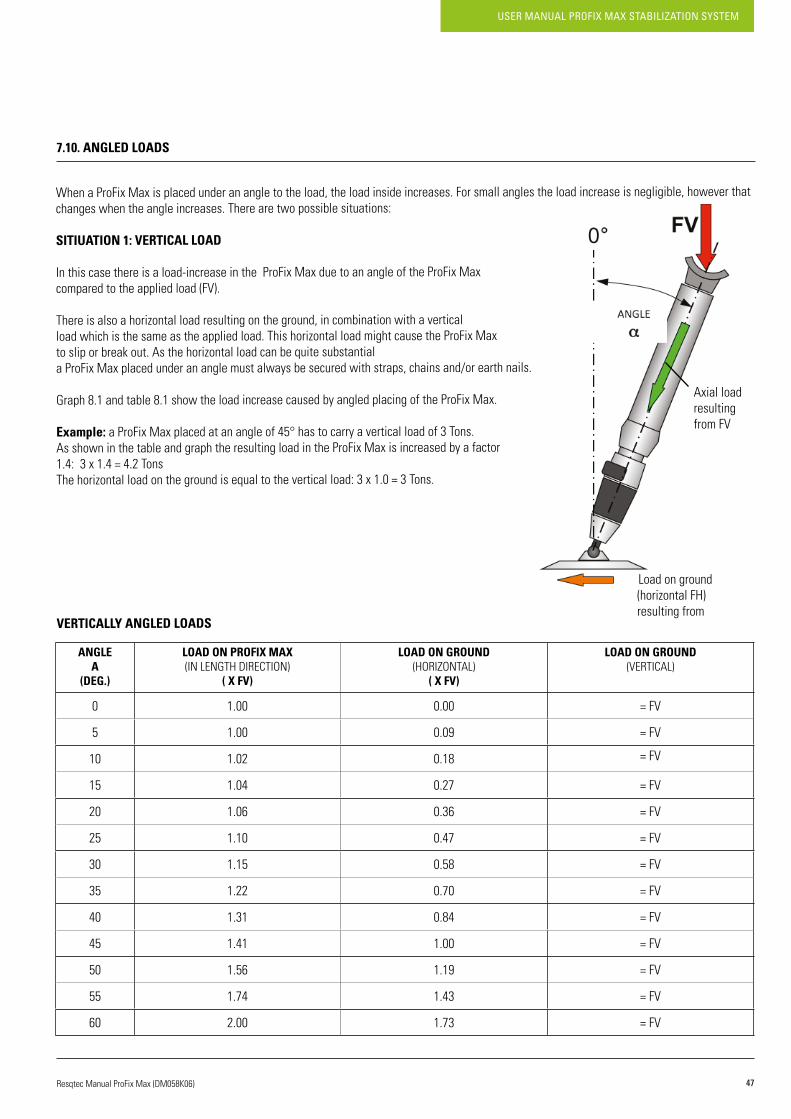
7.10. ANGLED LOADS
When a ProFix Max is placed under an angle to the load, the load inside increases. For small angles the load increase is negligible, however that changes when the angle increases. There are two possible situations:
SITIUATION 1: VERTICAL LOAD
Inthiscasethereisaload-increaseintheProFixMaxduetoanangleoftheProFixMaxcomparedtotheappliedload(FV).
There is also a horizontal load resulting on the ground, in combination with a verticalload which is the same as the applied load. This horizontal load might cause the ProFix Max to slip or break out. As the horizontal load can be quite substantiala ProFix Max placed under an angle must always be secured with straps, chains and/or earth nails.
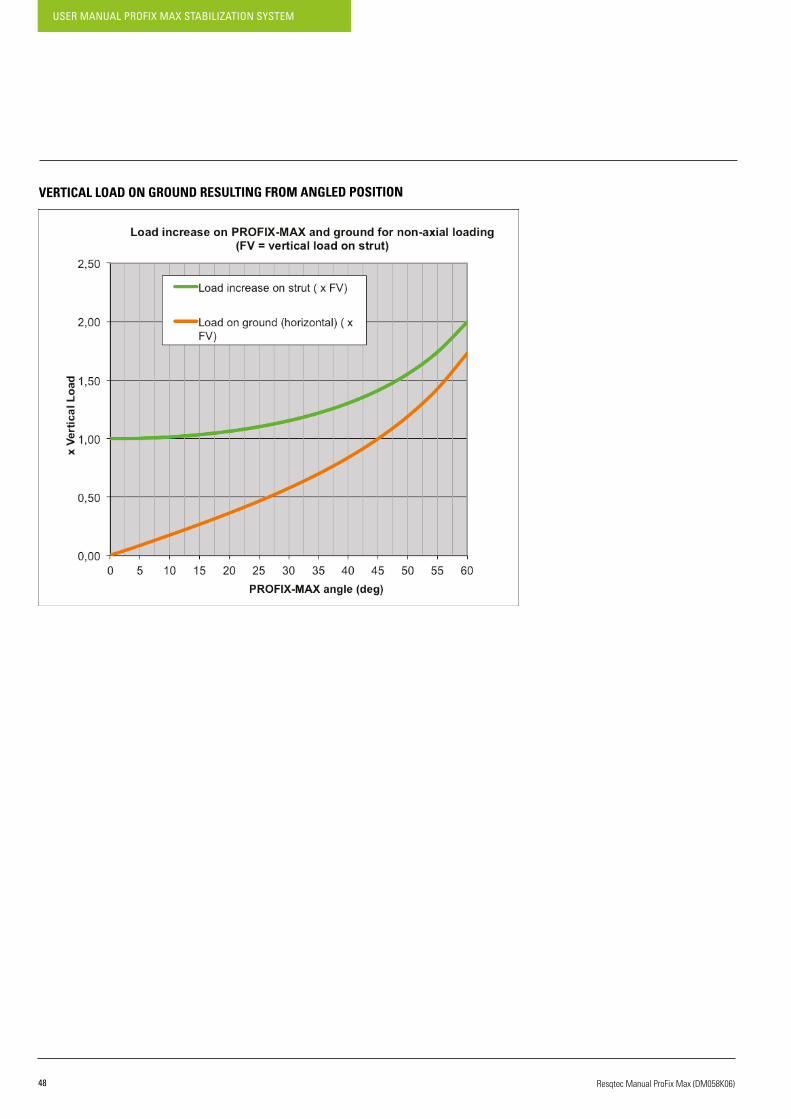
Graph 8.1 and table 8.1 show the load increase caused by angled placing of the ProFix Max.
Example:aProFixMaxplacedatanangleof45°hastocarryaverticalloadof3Tons.As shown in the table and graph the resulting load in the ProFix Max is increased by a factor 1.4: 3 x 1.4 = 4.2 TonsThe horizontal load on the ground is equal to the vertical load: 3 x 1.0 = 3 Tons.
VERTICALLY ANGLED LOADS
Axial load resultingfromFV
Load on ground (horizontal FH) resulting from
ANGLEA
(DEG.)
LOAD ON PROFIX MAX(IN LENGTH DIRECTION)
( X FV)
LOAD ON GROUND(HORIZONTAL)
( X FV)
LOAD ON GROUND(VERTICAL)
0 1.00 0.00 =FV
5 1.00 0.09 =FV
10 1.02 0.18 =FV
15 1.04 0.27 =FV
20 1.06 0.36 =FV
25 1.10 0.47 =FV
30 1.15 0.58 =FV
35 1.22 0.70 =FV
40 1.31 0.84 =FV
45 1.41 1.00 =FV
50 1.56 1.19 =FV
55 1.74 1.43 =FV
60 2.00 1.73 =FV
USER MANUAL PROFIX MAX STABILIZATION SYSTEM
48 Resqtec Manual ProFix Max (DM058K06)
VERTICAL LOAD ON GROUND RESULTING FROM ANGLED POSITION

49
USER MANUAL PROFIX MAX STABILIZATION SYSTEM
Resqtec Manual ProFix Max (DM058K06)
SITUATION 2: HORIZONTAL LOAD
When a ProFix Max is used in a raker system there is a horizontal load (FH) acting on the ProFix Max which also results in an increased axial load. There is also a horizontal load resulting on the ground, in combination with a verticalload which is the same as the applied load. The horizontal resulting load might cause the ProFix Max to slip or break out. As the horizontal load can be quite substantial a ProFix Max placed under an angle must always be secured with straps, chains and/or earth nails.
Graph 8.2 and table 8.2 show the load increase caused by angled placing of the ProFix Max.
Example:aProFixMaxplacedatanangleof30°hastocarryahorizontalloadof1.5Ton.As shown in the table and graph the resulting load in the ProFix Max is increased by a factor 2: 1.5 x 2 = 3 Tons.Theverticalloadonthegroundisequaltothehorizontalloadmultipliedby1.73:thereforetheverticalloadonthegroundis:1.5x1.73=2.6TonsThe horizontal load on the ground is equal to the horizontally applied load.
HORIZONTALLY ANGLED LOADS
Axial loadresulting from FH
Load on ground (vertical) resulting from FH
ANGLEA
(DEG.)
LOAD ON PROFIX MAX(IN LENGTH DIRECTION)
( X FV)
LOAD ON GROUND(VERTICAL)
( X FV)
10 5.76 5.67
15 3.86 3.73
20 2.92 2.75
25 2.37 2.14
30 2.00 1.73
35 1.74 1.43
40 1.56 1.19
45 1.41 1.00
50 1.31 0.84
55 1.22 0.70
60 1.15 0.58

USER MANUAL PROFIX MAX STABILIZATION SYSTEM
50 Resqtec Manual ProFix Max (DM058K06)
HORIZONTALLY LOAD ON GROUND RESULTING FROM ANGLED POSITION
51
USER MANUAL PROFIX MAX STABILIZATION SYSTEM
Resqtec Manual ProFix Max (DM058K06)
8.TROUBLESHOOTING
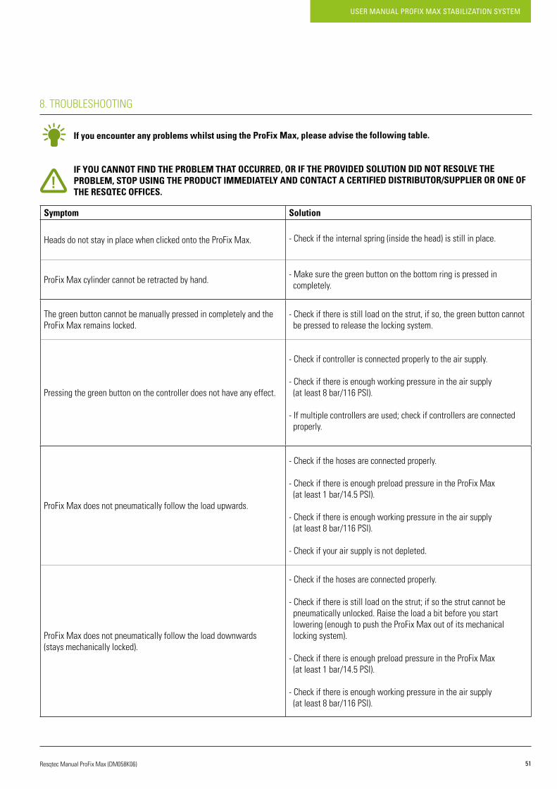
If you encounter any problems whilst using the ProFix Max, please advise the following table.
IF YOU CANNOT FIND THE PROBLEM THAT OCCURRED, OR IF THE PROVIDED SOLUTION DID NOT RESOLVE THE PROBLEM, STOP USING THE PRODUCT IMMEDIATELY AND CONTACT A CERTIFIED DISTRIBUTOR/SUPPLIER OR ONE OF THE RESQTEC OFFICES.
Symptom Solution
Heads do not stay in place when clicked onto the ProFix Max. -Checkiftheinternalspring(insidethehead)isstillinplace.
ProFix Max cylinder cannot be retracted by hand. -Makesurethegreenbuttononthebottomringispressedin completely.
The green button cannot be manually pressed in completely and the ProFix Max remains locked.
-Checkifthereisstillloadonthestrut,ifso,thegreenbuttoncannot be pressed to release the locking system.
Pressing the green button on the controller does not have any effect.
-Checkifcontrollerisconnectedproperlytotheairsupply.
-Checkifthereisenoughworkingpressureintheairsupply (at least 8 bar/116 PSI).
-Ifmultiplecontrollersareused;checkifcontrollersareconnected properly.
ProFix Max does not pneumatically follow the load upwards.
-Checkifthehosesareconnectedproperly.
-CheckifthereisenoughpreloadpressureintheProFixMax (at least 1 bar/14.5 PSI).
-Checkifthereisenoughworkingpressureintheairsupply (at least 8 bar/116 PSI).
-Checkifyourairsupplyisnotdepleted.
ProFix Max does not pneumatically follow the load downwards(stays mechanically locked).
-Checkifthehosesareconnectedproperly.
-Checkifthereisstillloadonthestrut;ifsothestrutcannotbe pneumatically unlocked. Raise the load a bit before you start lowering (enough to push the ProFix Max out of its mechanical locking system).
-CheckifthereisenoughpreloadpressureintheProFixMax (at least 1 bar/14.5 PSI).
-Checkifthereisenoughworkingpressureintheairsupply (at least 8 bar/116 PSI).

USER MANUAL PROFIX MAX STABILIZATION SYSTEM
52 Resqtec Manual ProFix Max (DM058K06)
9. WARRANTY
Resqtec offers two years warranty upon the purchase of this product. For extending your warranty or information about the Resqtec service program, please contact your Resqtec distributor/supplier.
WARRANTY IS ONLY VALID IF THE REGULATIONS AND RESTRICTIONS, AS DESCRIBED IN THE USER MANUAL APPLICABLE ON THE USED PRODUCT(S), ARE UNDERSTOOD AND FOLLOWED, AND IF THE MAINTENANCE AS ADVISED IN THE USER MANUAL IS DONE BY AN AUTHORIZED RESQTEC TECHNICIAN. DISREGARDING ANY OF THE APPLICABLE REGULATIONS AND RESTRICTIONS, AS DESCRIBED IN THE USER MANUAL APPLICABLE ON THE USED PRODUCT(S), WILL CAUSE THE WARRANTY TO VOID.
53
USER MANUAL PROFIX MAX STABILIZATION SYSTEM
Resqtec Manual ProFix Max (DM058K06)
10. DISCLOSURE
All rights reserved. No part of this publication whatsoever may be reproduced without the prior written consent of Resqtec.
All information herein was carefully gathered and examined. However, we cannot be held responsible for eventual mistakes or incompleteness. Resqtecmayexercisetherighttochangeormodifypartsoftheequipmentatanytimewithoutnotification.Thismanualmaybesubjecttoerror,revisionandtechnicalmodifications.Fordetailedinformation,andasweconstantlyimproveourequipment,pleasecheckthelatestspecificationsheet. This manual is based on and refers to current production models only. Resqtec accepts no liability for any damage and/or injuries resulting from the use of this manual in connection with any equipment which has been or may be supplied. For any additional information concerning the useofthemanualorthemaintenanceorrepairofResqtecequipment,pleasecontacttheResqtecdistributor/supplieroranofficiallyappointeddistributor/supplier. Utmost care has been taken in the preparation and accuracy of this manual. Resqtec cannot however be held liable for errors, omissions or consequential liabilities in the use of it.
USER MANUAL PROFIX MAX STABILIZATION SYSTEM
54 Resqtec Manual ProFix Max (DM058K06)
11. CONTACT
ADDRESSES RESQTEC OFFICES
Europeanoffice
Meer en Duin 822163 HC Lisse, the NetherlandsT +31 (0)252 419002F+31(0)252411794
E [email protected] www.resqtec.com
USAoffice
300 Forge Way, Suite 2Rockaway,NewJersey,07866T:+19736274646F:+19736274622
Asiaoffice
Lot 5, Jalan Delima 1/1 SubangHi-TechIndustrialPark47500Selangor,MalaysiaT +603 5621 5298F +603 5621 2895

RESQTEC Zumro B.V.
Meer en Duin 82 2163 HC Lisse, the Netherlands
T +31 (0)252 419002 F+31(0)252411794E [email protected] WWW.RESQTEC.COM