User Manual UPOS-211
91
User Manual UPOS-211 Intel® Celeron®J1900/Core™ i5 6300U/Core™ i3 6100U/Celeron® 3955U Processor-based Ubiquitous POS with 15" TFT LCD
Transcript of User Manual UPOS-211

User Manual
UPOS-211
Intel® Celeron®J1900/Core™ i5 6300U/Core™ i3 6100U/Celeron® 3955U Processor-based Ubiquitous POS with 15" TFT LCD
CopyrightThe documentation and the software included with this product are copyrighted 2017by Advantech Co., Ltd. All rights are reserved. Advantech Co., Ltd. reserves the rightto improve the products described in this manual at any time without notice. No partof this manual may be reproduced, copied, translated, or transmitted in any form orby any means without the prior written permission of Advantech Co., Ltd. The infor-mation provided in this manual is intended to be accurate and reliable. However,Advantech Co., Ltd. assumes no responsibility for its use, nor for any infringementsof the rights of third parties that may result from its use.
AcknowledgementsIntel and Pentium are trademarks of Intel Corporation.
Microsoft Windows is registered trademark of Microsoft Corp.
All other product names or trademarks are properties of their respective owners.
Product Warranty (2 years)Advantech warrants the original purchaser that all of its products will be free fromdefects in materials and workmanship for two years from the date of purchase.
This warranty does not apply to any products that have been repaired or altered bypersons other than repair personnel authorized by Advantech, or products that havebeen subject to misuse, abuse, accident, or improper installation. Under the terms ofthis warranty, Advantech assumes no liability as a consequence of such events.
Because of Advantech’s high quality-control standards and rigorous testing, mostcustomers never need to use our repair service. If an Advantech product is defective,it will be repaired or replaced free of charge during the warranty period. For out-of-warranty repairs, customers will be billed the cost of replacement materials, servicetime, and freight. Please consult your dealer for more details.
If you suspect your product is defective, follow the steps outlined below.
1. Collect all the information about the problem encountered. (For example, CPU speed, Advantech products used, other hardware and software used, etc.) Note anything abnormal and list any onscreen messages that are displayed when the problem occurs.
2. Call your dealer and describe the problem. Please have your manual, product, and any relevant information to hand.
3. If your product is diagnosed as defective, obtain a return merchandize authori-zation (RMA) number from your dealer. This allows us to process your return more quickly.
4. Carefully pack the defective product, a completed Repair and Replacement Order Card, and a proof of purchase date (such as a photocopy of your sales receipt) into a shippable container. Products returned without a proof of pur-chase date are not eligible for warranty service.
5. Write the RMA number clearly on the outside and ship the package prepaid to your dealer.
Part No. 2008211D10 Edition 1
Printed in China October 2017
UPOS-211 User Manual ii
Warnings, Cautions, and Notes
Document FeedbackTo assist us in improving this manual, we welcome any comments and constructivecriticisms. Please send all feedback in writing to [email protected]
Technical Support and Assistance1. Visit the Advantech website at http://support.advantech.com to obtain the latest
product information.2. Contact your distributor, sales representative, or Advantech's customer service
center for technical support if you need additional assistance. Please have the following information ready before calling:– Product name and serial number– Description of your peripheral attachments– Description of your software (operating system, version, application software, etc.)– Comprehensive description of the problem– The exact wording of any error messages
Packing ListBefore setting up the system, check that the items listed below are included in theshipment and in good condition.
UPOS-211 Series– Warranty card– Adaptor– User manual– 2 x COM Cable– 1 x HDD Bracket
If any of these items are missing or damaged, please contact your distributor or salesrepresentative immediately.
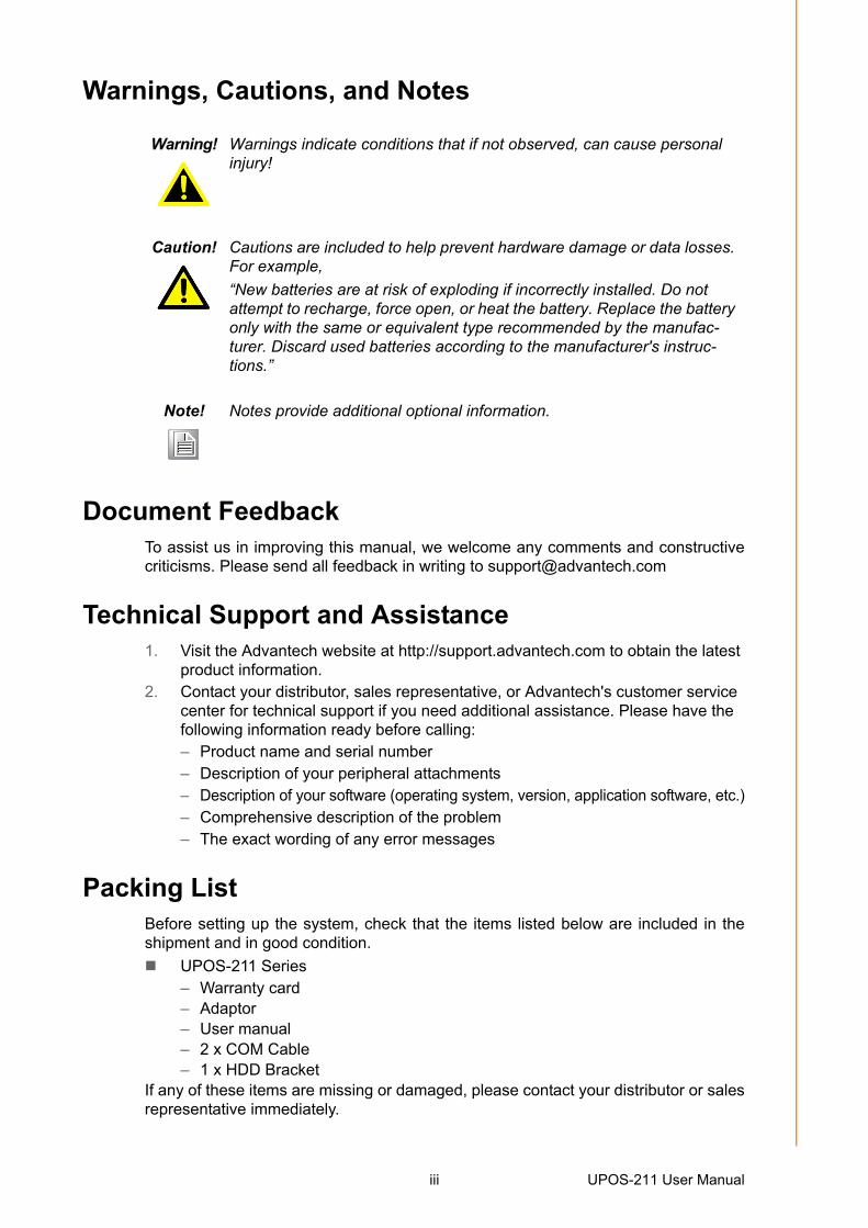
Warning! Warnings indicate conditions that if not observed, can cause personal injury!
Caution! Cautions are included to help prevent hardware damage or data losses. For example,
“New batteries are at risk of exploding if incorrectly installed. Do not attempt to recharge, force open, or heat the battery. Replace the battery only with the same or equivalent type recommended by the manufac-turer. Discard used batteries according to the manufacturer's instruc-tions.”
Note! Notes provide additional optional information.
iii UPOS-211 User Manual
Safety Instructions1. Read these safety instructions carefully.2. Retain this user manual for future reference.3. Disconnect this equipment from all AC outlets before cleaning. Use only a damp
cloth to clean. Do not use liquid or spray detergents.4. For pluggable equipment, the power outlet socket must be located near the
equipment and easily accessible.5. Protect this equipment from humidity.6. Place this equipment on a reliable surface during installation. Dropping or letting
the device fall may cause damage.7. The openings on the enclosure are for air convection. Protect the equipment
from overheating. Do not cover the openings.8. Ensure the voltage is correct before connecting the equipment to a power outlet.9. Position the power cord away from high-traffic areas. Do not place anything over
the power cord.10. All cautions and warnings on the equipment should be noted.11. If unused for a long time, disconnect the equipment from the power source to
avoid damage from transient overvoltage.12. Never pour liquid into an opening. This may cause fire or electrical shock.13. Never open the equipment. For safety reasons, the equipment should be
opened only by qualified service personnel.14. If one of the following situations occurs, have the equipment checked by service
personnel:The power cord or plug is damaged.Liquid has penetrated the equipment.The equipment has been exposed to moisture.The equipment is malfunctioning, or does not operate according to the user
manual.The equipment has been dropped and damaged.The equipment has obvious signs of breakage.
15. Do not store this equipment in an environment where the temperature fluctuates below -20 °C (-4 °F) or above 60 °C (140 °F) as this may cause damage. The equipment should be stored in a controlled environment.
16. Batteries are at risk of exploding if incorrectly installed. Replace only with the same or equivalent type recommended by the manufacturer. Discard used bat-teries according to the manufacturer’s instructions.
The sound pressure level at the operator position does not exceed 70 dB (A) inaccordance with IEC 704-1:1982.
DISCLAIMER: These instructions are provided according to IEC 704-1. Advantechdisclaims all responsibility for the accuracy of any statements contained herein.
UPOS-211 User Manual iv

Safety Precaution - Static ElectricityFollow these simple precautions to protect yourself from harm and the products fromdamage.
To avoid electrical shock, always disconnect the power from your PC chassis before you work on it. Don't touch any components on the CPU card or other cards while the PC is on.
Disconnect power before making any configuration changes. The sudden rush of power as you connect a jumper or install a card may damage sensitive elec-tronic components.
v UPOS-211 User Manual

UPOS-211 User Manual vi

Contents
Chapter 1 General Information ............................11.1 Introduction ............................................................................................... 21.2 Specifications ............................................................................................ 2
1.2.1 General Specifications .................................................................. 21.2.2 Environmental Specifications........................................................ 21.2.3 Touch Screen................................................................................ 21.2.4 LCD Specifications........................................................................ 3
1.3 Dimensions ............................................................................................... 3
Chapter 2 System Setup.......................................52.1 Quick Tour of the Device........................................................................... 6
Figure 2.1 Front view of UPOS-211............................................. 6Figure 2.2 Rear view of UPOS-211 ............................................. 6Figure 2.3 IO Connectors of UPOS-211 ...................................... 7
2.2 Installation Procedures.............................................................................. 72.2.1 Connecting the Power Cord.......................................................... 72.2.2 Connecting the Mouse and Keyboard........................................... 72.2.3 Activating the Power Source......................................................... 7
2.3 Installing System Software........................................................................ 82.4 Installing the HDD ..................................................................................... 92.5 Peripheral Cable Connection & Arrangement ......................................... 142.6 How to select Windows 7 ........................................................................ 182.7 Jumpers and Connectors ........................................................................ 19
Table 2.1: Jumpers.................................................................... 19Table 2.2: Connectors ............................................................... 20
2.8 PenMount 6000 Multiple-Monitors set sop.............................................. 212.9 Capacitive touch extends display setup .................................................. 23
2.10 Peripheral and base ................................................................................ 252.10.1 MSR............................................................................................ 252.10.2 VESA mount ............................................................................... 262.10.3 10-inch screen ............................................................................ 272.10.4 2nd display.................................................................................. 282.10.5 VDF............................................................................................. 312.10.6 Barcode scanner......................................................................... 332.10.7 Wall mount .................................................................................. 35
Chapter 3 BIOS Setup(UPOS-211D)37
3.1 Introduction ............................................................................................. 383.2 BIOS Setup ............................................................................................. 38
3.2.1 Main Menu .................................................................................. 393.2.2 Advanced BIOS Features ........................................................... 403.2.3 Configuration Setting .................................................................. 533.2.4 Security Configuration Setting .................................................... 583.2.5 Boot Configuration ...................................................................... 593.2.6 Save & Exit Configuration Setting............................................... 60
Chapter 4 BIOS Setup
vii UPOS-211 User Manual

(UPOS-211F)614.1 Introduction ............................................................................................. 624.2 BIOS Setup ............................................................................................. 62
4.2.1 Main Menu.................................................................................. 624.2.2 Advanced BIOS Features ........................................................... 634.2.3 Chipset Configuration Setting ..................................................... 754.2.4 Security Configuration Setting .................................................... 794.2.5 Boot Configuration ...................................................................... 804.2.6 Save & Exit Configuration Setting............................................... 81
UPOS-211 User Manual viii

Chapter 1
1 General InformationThis chapter provides basic information regarding UPOS-211.Introduction
Specifications
Dimensions

1.1 IntroductionUPOS-211 is an all-in-one point-of-sale (POS) system that features a small footprintand dual-hinge design, making it ideal for countertops and limited-space installations.
Powered by Intel® Celeron®J1900/Core™ i5 6300U/Core™ i3 6100U/Celeron®3955U processors, UPOS-211 ensures high-performance computing and reliabledata processing, while supporting flexible customization for diverse applications. TheIP65-rated front panel is water and dust resistance. UPOS-211 is a competitive cost,and energy effective platform built for retail and hospitality.
1.2 Specifications
1.2.1 General Specifications Dimensions (W x H x D): 354x327x237 mm, stand: 237 x 200 mm Weight: 5.2 kg (Net Weight) / 6.9 kg (Gross Weight) Power supply:
– 60W (100-240Vac,50-60Hz,1.5A) power adapter Storage: 1 x 2.5" SATA HDD/SSD connector CPU: Intel® Celeron®J1900/Core™ i5 6300U/Core™ i3 6100U/Celeron®
3955U processors. RAM: Support 1 x 204-pin DDR3L 1333 Mhz SO-DIMM, up to 8 GB/ 1 x 260-pin
DDR4 2333 Mhz SO-DIMM, up to 16GB Serial ports:
– External: 2 x COM RS232 ports via RJ-48 connector, – Internal: 4 x COM port, COM3 for touch, COM6 no power, COM4, 5 support
5V & 12V by order via box header USB:
– UPOS-211F: 2xUSB3.0,3xUSB2.0– UPOS-211D: 1xUSB3.0,4xUSB2.0
Front panel: IP65 sealed front panel with true flat touch screen Cash drawer: 1 x RJ11 Ethernet: 1 x RJ-45 Gigabit LAN Display port: 1 x VGA, 1 x DP Expansion slot: 1 x Mini PCIe (for Wifi or 3G), shared with mini SATA
connector Audio: 1 x Speaker LPT port: 1 LPT port (optional)
1.2.2 Environmental Specifications Operating Temperature: 0 ~ 40 °C (32 ~ 104 °F) Relative humidity: 10 ~ 90% @ 40 °C (non-condensing) Shock: 10 G peak acceleration (11 ms duration) Vibration: 5 ~ 500 Hz 0.5 Grms, random Certification: CCC, CE, UL, FCC, CB, BSMI
1.2.3 Touch Screen Type: True Flat, 5-Wire Resistive Touch / Projected CAP Touch Light Transmission: 80% +/-5% / 80%+/-3%
UPOS-211 User Manual 2

Chapter 1
GeneralInform
ation
1.2.4 LCD Specifications. Display Type: 15" TFT LCD Max.Resolution: 1024 x 768 Colors: 262 K Pixel Pitch (um): 297 (H) x 297 (W) View Angle: 80° (H) / 70° (V) Luminance: 250 cd/m2
1.3 Dimensions
Note! The color LCD display installed in the UPOS-211 is high-quality and reli-able. However, it may contain a few defective pixels which do not always illuminate. With current technology, it is impossible to completely eliminate defective pixels. Advantech is actively working to improve the technology.
3 UPOS-211 User Manual

UPOS-211 User Manual 4

Chapter 2
2 System SetupThis chapter details the system setup process for UPOS-211.Quick Tour of the Device
Installation Procedures
Installing System Software
Installing the HDD
Peripheral Cable Connection & Arrangement
How to select Windows 7
Jumpers and Connectors
PenMount 6000 Multiple-Monitors set sop
Capacitive touch extend display set sop
Peripheral and base

2.1 Quick Tour of the Device Before setting up the device, take a moment to familiarize yourself with the functionsof the controls, drivers, connectors, and ports located on the front panel, as illustratedin the figures below.
Figure 2.1 Front view of UPOS-211
Turn the computer to view the I/O, as shown in Figure 2.2 and 2.3. The I/O interfacesinclude serial ports, USB slots, VGA port, Ethernet port, RJ-11, DP, and power inlet.
Figure 2.2 Rear view of UPOS-211
UPOS-211 User Manual 6

Chapter 2
System
Setup
Figure 2.3 IO Connectors of UPOS-211
2.2 Installation Procedures
2.2.1 Connecting the Power CordThis product only supports DC power (12 VDC, max. 60 W). Be sure to hold the plugend when plugging or unplugging the power cord.
2.2.2 Connecting the Mouse and KeyboardConnect the mouse and keyboard via the USB ports located in the I/O section at therear of the computer.
2.2.3 Activating the Power SourceVerify that the power cord is connected to the power input port of the device. Thenconnect the plug end of the power cord to the wall power outlet.
7 UPOS-211 User Manual

2.3 Installing System SoftwareRecent OS releases include setup programs that load automatically and guide usersthrough the entire installation process. The steps necessary to install an operatingsystem on the computer hard drive are explained below.
If necessary, insert the OS CD into the diskette until the release button pops up.
The system BIOS supports bootup directly from the USB-CDROM drive. Users caninsert the OS CD directly into the USB-CDROM drive.
Power on the computer, or reset the system by pressing “Ctrl” + “Alt” + “Del” simulta-neously.
Select Chipset->OS Selection to install the correct->Operation System Select toinstall the correct OS.
After clicking “Save & Exit”, the computer will automatically load the operating systemfrom the diskette or USB-CDROM drive.
When presented with the opening screen of a setup/installation program, simply fol-low the onscreen instructions. The setup program guides users through configuringand installing the hard drive and operating system.
Note! Some distributors and system integrators may have pre-installed system software before shipping the computer.
Note! The drivers and utilities of UPOS-211 are subject to change without notice. If in doubt, check Advantech’s website or contact our application engineers for the latest information regarding drivers and utilities.
UPOS-211 User Manual 8

Chapter 2
System
Setup
2.4 Installing the HDD1. Take the HDD bracket and screws out of the accessory box.
2. Assemble the HDD and fasten the screws.
9 UPOS-211 User Manual

3. Take out the POS system and push the screen upward.
UPOS-211 User Manual 10
Chapter 2
System
Setup
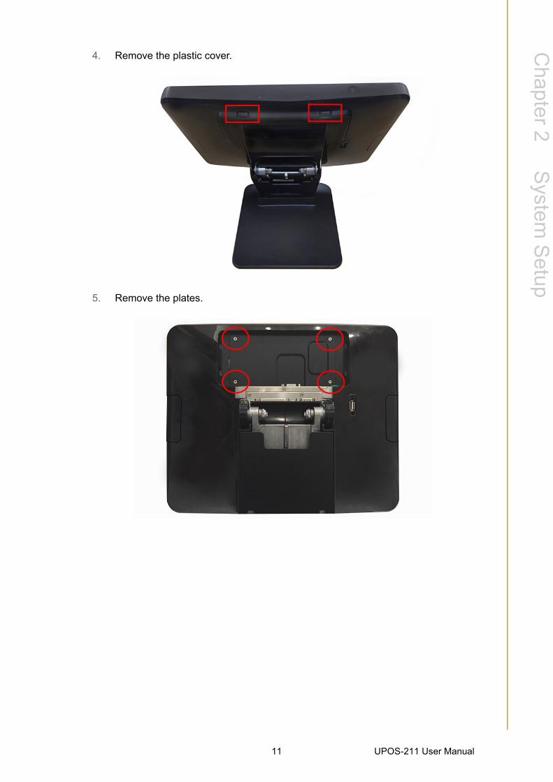
4. Remove the plastic cover.
5. Remove the plates.
11 UPOS-211 User Manual

6. Install the HDD and fasten the screws.
7. Replace the plates and fasten the screws.
UPOS-211 User Manual 12

Chapter 2
System
Setup
8. Replace the plastic cover.
9. Push the screen back to the original position.
13 UPOS-211 User Manual

2.5 Peripheral Cable Connection & Arrangement1. Take out the POS system and push the screen upward.
UPOS-211 User Manual 14
Chapter 2
System
Setup
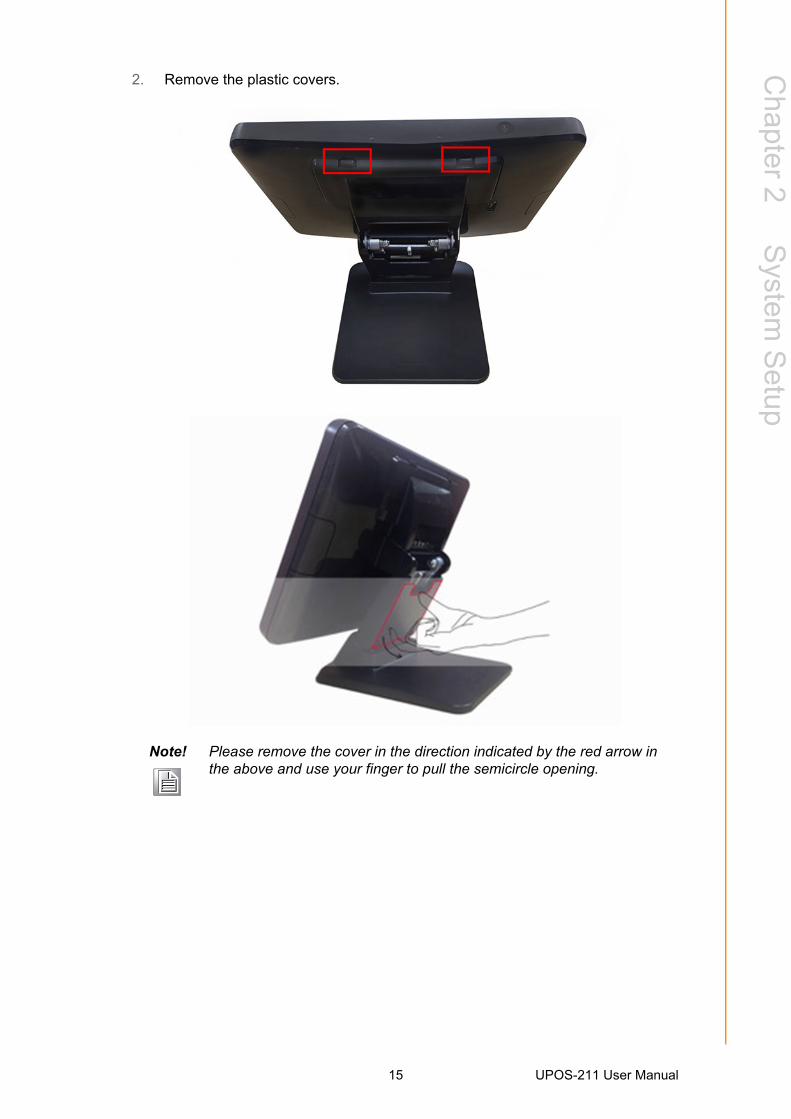
2. Remove the plastic covers.
Note! Please remove the cover in the direction indicated by the red arrow in the above and use your finger to pull the semicircle opening.
15 UPOS-211 User Manual

3. First, make the I/O cables traverse the base as shown below, then connect the cables to the I/O board of the screen.
4. Replace the plastic covers.
UPOS-211 User Manual 16
Chapter 2
System
Setup
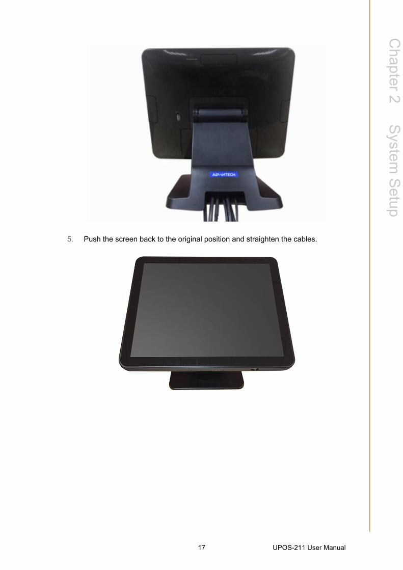
5. Push the screen back to the original position and straighten the cables.
17 UPOS-211 User Manual

2.6 How to select Windows 7UPOS-211 supports Win 7 Pro, Win 8.1 Industry Pro & Win10 IoT. The default OS inBIOS is Win 8.1 & Win10. So, if a user wants to install Windows 7, just go to the BIOSSetup screen and select Windows 7, same with the other OS.
1. Connect a Keyboard to the USB port on UPOS-211 backside cover.2. Power on UPOS-211, when you see the windows logo, press DEL to enter the
BIOS setup window. Please click Chipset “South Bridge” OS Selection, then select Windows 7.
3. Press ”F4” on the Keyboard to save the configuration. Then click YES. The device will be restarted and users can install Windows 7.
UPOS-211 User Manual 18

Chapter 2
System
Setup
2.7 Jumpers and ConnectorsConnectors on the PCM-8518 motherboard link it to devices such as hard disk drivesand a keyboard. In addition, the board has a number of jumpers used to configureyour system for your application.
The tables below list the functions of each of the board jumpers and connectors.
Later sections in this chapter give instructions on setting jumpers and gives instructions for connecting external devices to your motherboard.
JP1
This jumper allows you to clear the Real Time Clock (RTC) RAM in CMOS
CN34
PIN1 5v
PIN2 LCD POWER
PIN3 3.3V
COM RI/+5V/+12V Select (COM_RI)
This jumper allows you to select the power mode of COM PORT, default RI.
JP_CASHV1
PIN1 12V
PIN2 cash drawer power
Pin3 24V
Note: PCB silkscreen “ ▽ ”mark pin1.
Table 2.1: Jumpers
Label Function
JP1 Clear CMOS
JCOM1 RI/+5V/+12V select
JCOM2 RI/+5V/+12V select
JCOM4 RI/+5V/+12V select
JCOM5 RI/+5V/+12V select
CN34 LCD +3V/+5V select
19 UPOS-211 User Manual
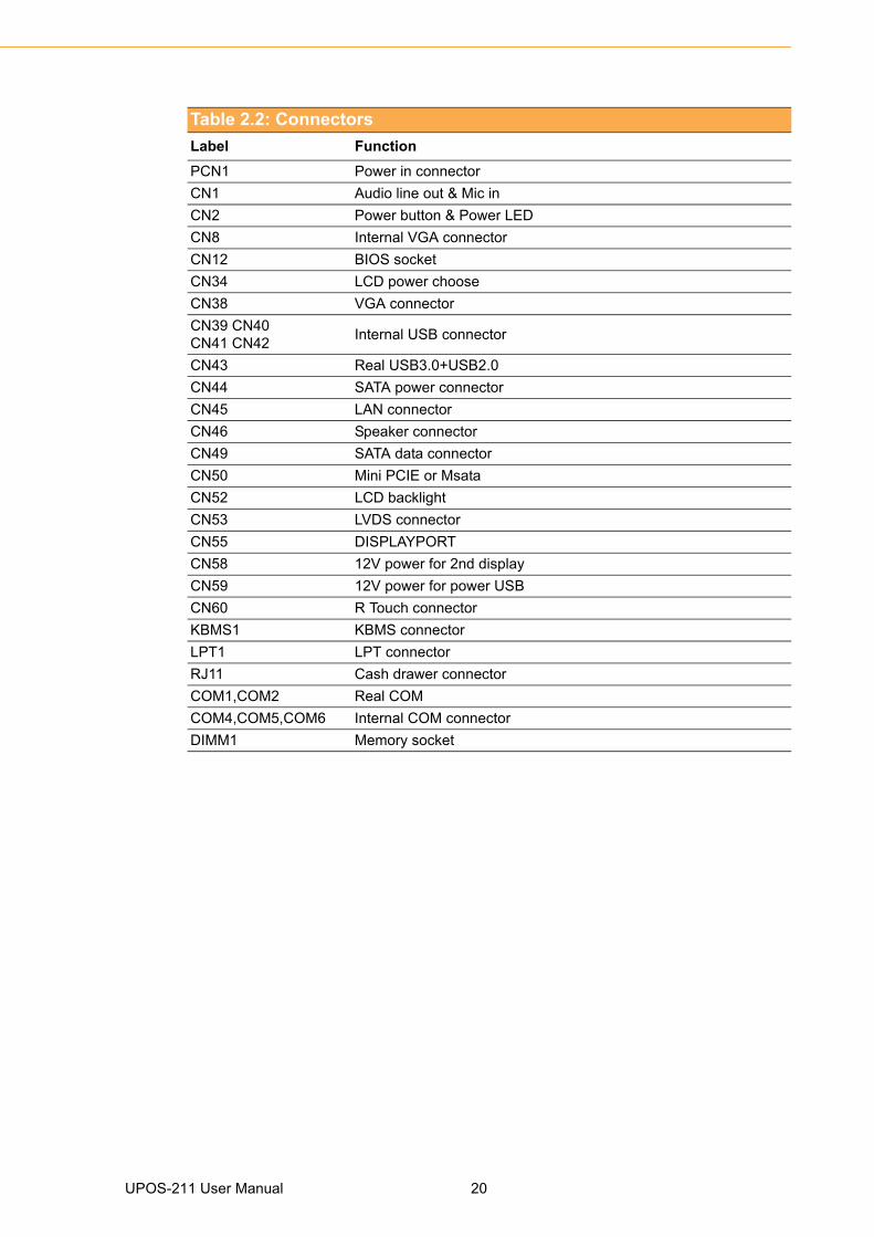
Table 2.2: Connectors
Label Function
PCN1 Power in connector
CN1 Audio line out & Mic in
CN2 Power button & Power LED
CN8 Internal VGA connector
CN12 BIOS socket
CN34 LCD power choose
CN38 VGA connector
CN39 CN40 CN41 CN42
Internal USB connector
CN43 Real USB3.0+USB2.0
CN44 SATA power connector
CN45 LAN connector
CN46 Speaker connector
CN49 SATA data connector
CN50 Mini PCIE or Msata
CN52 LCD backlight
CN53 LVDS connector
CN55 DISPLAYPORT
CN58 12V power for 2nd display
CN59 12V power for power USB
CN60 R Touch connector
KBMS1 KBMS connector
LPT1 LPT connector
RJ11 Cash drawer connector
COM1,COM2 Real COM
COM4,COM5,COM6 Internal COM connector
DIMM1 Memory socket
UPOS-211 User Manual 20

Chapter 2
System
Setup
2.8 PenMount 6000 Multiple-Monitors set sopBefore using multiple monitors you must have two or more monitors that are in exten-sion mode.
Enabling Multiple Monitors
Enable the multiple display function as follows:
1. In the PenMount Control Panel, under Multiple Monitors tag, check the “Multiple Monitor Support” box. Then click “Map Touchscreens” to assign touch control-lers to displays.
Note! Before you can use multiple monitors you need to map each monitor.
21 UPOS-211 User Manual
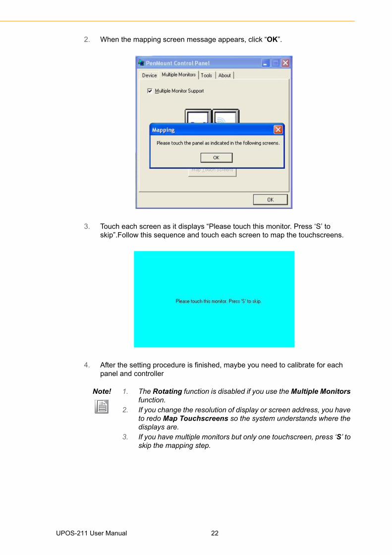
2. When the mapping screen message appears, click “OK”.
3. Touch each screen as it displays “Please touch this monitor. Press ‘S’ to skip”.Follow this sequence and touch each screen to map the touchscreens.
4. After the setting procedure is finished, maybe you need to calibrate for each panel and controller
Note! 1. The Rotating function is disabled if you use the Multiple Monitors function.
2. If you change the resolution of display or screen address, you have to redo Map Touchscreens so the system understands where the displays are.
3. If you have multiple monitors but only one touchscreen, press ‘S’ to skip the mapping step.
UPOS-211 User Manual 22

Chapter 2
System
Setup
2.9 Capacitive touch extends display setupIf you use Dual display, refer to the instructions below.
1. Open Control Panel, choose Tablet PC as below.
2. Double click “Tablet PC setup’’, choose Touch screen, then click setup.
23 UPOS-211 User Manual

3. UPOS-211D main screen will show the below picture. Please touch the main touch screen, then press ”Enter” on the keyboard. On the second display (see same picture), if the second display has a touch function, touch it; if the second display no touch function, then just press “Enter”.
4. Then click ”ok” to finish.
UPOS-211 User Manual 24

Chapter 2
System
Setup
2.10 Peripheral and base
2.10.1 MSR1. Remove the plastic cover.
2. Install the MSR.
25 UPOS-211 User Manual

3. Replace the plastic cover and fasten the screws.
2.10.2 VESA mount1. Assemble the VESA mount and fasten the screws.
UPOS-211 User Manual 26

Chapter 2
System
Setup
2.10.3 10-inch screen1. Assemble the 10-inch screen.
2. Fasten the screws.
27 UPOS-211 User Manual

3. Adjust the angle of the 10-inch screen.
2.10.4 2nd display1. Connect the cables to the I/O board.
UPOS-211 User Manual 28

Chapter 2
System
Setup
2. Fasten the screws.
29 UPOS-211 User Manual

3. Assemble the plastic cover and fasten the screws.
UPOS-211 User Manual 30

Chapter 2
System
Setup
2.10.5 VDF1. Remove the plastic cover.
2. Connect the cables to the I/O board.
31 UPOS-211 User Manual

3. Fasten the screws.
4. Adjust the angle of the VDF.
UPOS-211 User Manual 32

Chapter 2
System
Setup
2.10.6 Barcode scanner1. Fasten the screws.
2. Connect the cables to the I/O board and fasten the screws.
33 UPOS-211 User Manual

3. Replace the plastic cover.
4. Push the screen back to the original position.
UPOS-211 User Manual 34

Chapter 2
System
Setup
2.10.7 Wall mount1. Assemble the wall mount and fasten the screws.
35 UPOS-211 User Manual

2. Clasp the UPOS-211 to the wall.
UPOS-211 User Manual 36
Chapter 3
3 BIOS Setup(UPOS-211D)
In most cases, the computer will have been setup and configured by the dealer or SIprior to delivery. However, some of the computer's BIOS (Basic Input-Output System)setup programs may need adjustment to set the system configuration data, such asthe current date and time, or type of hard drive installed. The setup program is storedin read-only memory (ROM) and can be accessed when activating or resetting thecomputer, or by pressing “Delete” immediately after powering up the computer.
3.1 IntroductionWith the AMI BIOS Setup program, you can modify BIOS settings to control the spe-cial features of your computer. The Setup program uses a number of menus for mak-ing changes. This chapter describes the basic navigation of the UPOS-211 setupscreens.
3.2 BIOS SetupUPOS-211D has AMI BIOS built in, with a SETUP utility that allows users to config-ure required settings or to activate certain system features. The SETUP saves theconfiguration in the FLASH of the motherboard. When the Power is turned off, thebattery on the board supplies the necessary power to preserve the FLASH.When thepower is turned on, press the <Del> or <Esc> button during the BIOS POST (Power-On Self Test) to access the CMOS SETUP screen.
Control Keys
← >< → > Select Screen
< ↑ >< ↓ > Select Item
<Enter> Select
<+/-> Change Opt
<F1> General help
<F2> Previous Values
<F3> Optimized Defaults
<F4> Save & Exit
<Esc> Exit
UPOS-211 User Manual 38

Chapter 3
BIO
S S
etup(U
PO
S-211D
)
3.2.1 Main MenuPress <Del> or <Esc> to enter AMI BIOS CMOS Setup Utility, the Main Menu willappear on the screen. Use arrow keys to select among the items and press <Enter>to accept or enter the sub-menu.
The Main BIOS setup screen has two main frames. The left frame displays all theoptions that can be configured. Grayed-out options cannot be configured; options inblue can. The right frame displays the key legend.
Above the key legend is an area reserved for a text message. When an option isselected in the left frame, it is highlighted in white. Often a text message will accompany it.
System time / System dateUse this option to change the system time and date. Highlight System Time orSystem Date using the <Arrow> keys. Enter new values through the keyboard.Press the <Tab> key or the <Arrow> keys to move between fields. The datemust be entered in MM/DD/YY format. The time must be entered in HH:MM:SSformat.
39 UPOS-211 User Manual

3.2.2 Advanced BIOS FeaturesSelect the Advanced tab from the setup screen to enter the Advanced BIOS Setupscreen. You can select any of the items in the left frame of the screen, such as CPUConfiguration, to go to the sub menu for that item. You can display an AdvancedBIOS Setup option by highlighting it using the <Arrow> keys. All Advanced BIOSSetup options are described in this section. The Advanced BIOS Setup screen isshown below. The sub menus are described on the following pages.
UPOS-211 User Manual 40

Chapter 3
BIO
S S
etup(U
PO
S-211D
)
3.2.2.1 ACPI Settings
Enable ACPI Auto Configuration [Disabled]Enable or disable BIOS ACPI auto configuration.
Enable Hibernation [ Enabled ]Enables or Disables System ability to Hibernate (OS/S4 Sleep State). Thisoption may be not effective with some OS.
ACPI Sleep State [S3(Suspend to RAM) ]Select ACPI sleep state the system will enter when the SUSPEND button ispressed.
Lock Legacy Resources [Disabled ]Enables or Disables Lock of Legacy Resources.
41 UPOS-211 User Manual

3.2.2.2 NCT6106D Super IO Configuration
Super IO Chip [NCT6106D] Serial Port 1 Configuration
– Serial Port [Enabled]– Device Settings: IO=3F8h; IRQ =4
UPOS-211 User Manual 42

Chapter 3
BIO
S S
etup(U
PO
S-211D
)
Serial Port 2 Configuration
– Serial Port [Enabled]– Device Settings: IO=2F8h; IRQ =3
Serial Port 3 Configuration
– Serial Port [Enabled]– Device Settings: IO=3E8h; IRQ =5
43 UPOS-211 User Manual

Serial Port 4 Configuration
– Serial Port [Enabled]– Device Settings: IO=2E8h; IRQ =7
Serial Port 5 Configuration
– Serial Port [Enabled]– Device Settings: IO=2F0h; IRQ =7
UPOS-211 User Manual 44

Chapter 3
BIO
S S
etup(U
PO
S-211D
)
Serial Port 6 Configuration
– Serial Port [Enabled]– Device Settings: IO=2E0h; IRQ =10
Parallel Port Configuration
45 UPOS-211 User Manual

– Parallel Port [Enabled]To enable or disable Parallel Port
– Device Settings: IO=278h; IRQ =6– Change Settings [Auto]
To select an optimal setting for parallel port.– Device Mode [STD Printer Mode]
3.2.2.3 Hardware Monitor
UPOS-211 User Manual 46

Chapter 3
BIO
S S
etup(U
PO
S-211D
)
3.2.2.4 S5 RTC Wake Settings
47 UPOS-211 User Manual

3.2.2.5 CPU Configuration.
Intel Virtualization Technology [Enabled]
Enabled or Disable Intel Virtualization Technology.
UPOS-211 User Manual 48

Chapter 3
BIO
S S
etup(U
PO
S-211D
)
3.2.2.6 PPM Configuration
49 UPOS-211 User Manual
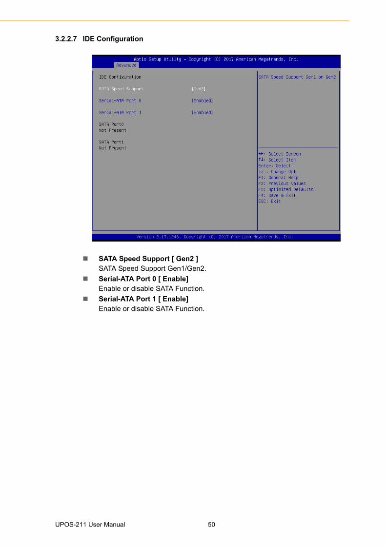
3.2.2.7 IDE Configuration
SATA Speed Support [ Gen2 ]SATA Speed Support Gen1/Gen2.
Serial-ATA Port 0 [ Enable]Enable or disable SATA Function.
Serial-ATA Port 1 [ Enable]Enable or disable SATA Function.
UPOS-211 User Manual 50

Chapter 3
BIO
S S
etup(U
PO
S-211D
)
3.2.2.8 CSM Configuration
51 UPOS-211 User Manual
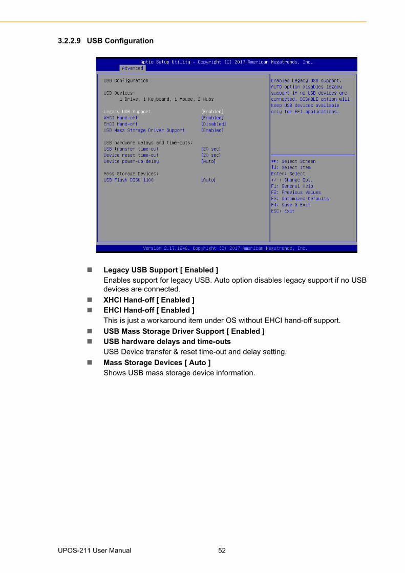
3.2.2.9 USB Configuration
Legacy USB Support [ Enabled ]Enables support for legacy USB. Auto option disables legacy support if no USBdevices are connected.
XHCI Hand-off [ Enabled ] EHCI Hand-off [ Enabled ]
This is just a workaround item under OS without EHCI hand-off support.
USB Mass Storage Driver Support [ Enabled ] USB hardware delays and time-outs
USB Device transfer & reset time-out and delay setting.
Mass Storage Devices [ Auto ]Shows USB mass storage device information.
UPOS-211 User Manual 52

Chapter 3
BIO
S S
etup(U
PO
S-211D
)
3.2.2.10 Security Configuration
3.2.3 Configuration SettingSelect the chipset tab from the BIOS setup screen to enter the Chipset Setup screen.
Users can select any item in the left frame of the screen, such as North Bridge Con-figuration to go to the sub menu for that item. The Chipset Setup screens are shownbelow. The submenus are described on the following pages.
53 UPOS-211 User Manual

3.2.3.1 North Bridge Configuration Setting
Choose Intel IGD Configuration
Primary IGFX Boot Display [Auto]Boot display Auto/CRT/DP/LVDS.
UPOS-211 User Manual 54

Chapter 3
BIO
S S
etup(U
PO
S-211D
)
3.2.3.2 South Bridge Configuration Setting
OS Selection [ Windows 8.x ]OS selection Windows 8.x/Windows 7.
XHCI Mode [ Enabled ]Enable or Disable XHCI mode.
Restore AC Power Loss [ Power off ] AC power loss power off/Power on/Last State. Mini PCIE Socket [ mSATA ] The Socket Function choose mSATA/PCIE.
55 UPOS-211 User Manual

Internal Speaker [Enabled ]Enable or disable speaker function.
UPOS-211 User Manual 56

Chapter 3
BIO
S S
etup(U
PO
S-211D
)
57 UPOS-211 User Manual

3.2.4 Security Configuration Setting
Administrator PasswordSelect this option and press <ENTER> to access the sub menu, and then typein the password. Set the Administrator password.
User PasswordSelect this option and press <ENTER> to access the sub menu, and then typein the password. Set the User Password.
UPOS-211 User Manual 58
Chapter 3
BIO
S S
etup(U
PO
S-211D
)
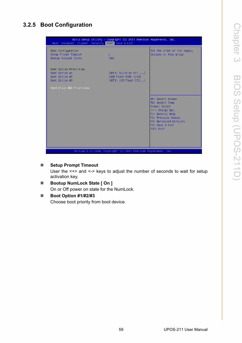
3.2.5 Boot Configuration
Setup Prompt TimeoutUser the <+> and <-> keys to adjust the number of seconds to wait for setupactivation key.
Bootup NumLock State [ On ]On or Off power on state for the NumLock.
Boot Option #1/#2/#3Choose boot priority from boot device.
59 UPOS-211 User Manual

3.2.6 Save & Exit Configuration Setting
Save Changes and ResetWhen users have completed system configuration, select this option to savechanges, exit BIOS setup menu and reboot the computer to take effect all sys-tem configuration parameters.
1. Select Exit Saving Changes from the Exit menu and press <Enter>. The following message appears: Save Configuration Changes and Exit Now? [Ok] [Cancel]
2. Select Ok or cancel. Discard Changes and Reset
Select this option to quit Setup without making any permanent changes to thesystem configuration1. Select Reset Discarding Changes from the Exit menuand press <Enter>.
1. The following message appears: Discard Changes and Exit Setup Now? [Ok] [Cancel]
2. Select Ok to discard changes and reset. Discard Changes.Select Discard Changes from the Exit menu and press <Enter>.
Restore DefaultThe BIOS automatically configures all setup items to optimal settings whenusers select this option. Defaults are designed for maximum system perfor-mance, but may not work best for all computer applications. In particular, do notuse the defaults if the user's computer is experiencing system configurationproblems. Select Restore Defaults from the Exit menu and press <Enter>.
Boot OverrideShows the boot device types on the system.
UPOS-211 User Manual 60
Chapter 4
4 BIOS Setup (UPOS-211F)
4.1 IntroductionWith the AMI BIOS Setup program, you can modify BIOS settings to control the spe-cial features of your computer. The Setup program uses a number of menus for mak-ing changes. This chapter describes the basic navigation of the UPOS-211 setupscreens.
4.2 BIOS SetupThe UPOS-211F Series system has AMI BIOS built in, with a SETUP utility thatallows Users to configure required settings or to activate certain system features.
The SETUP saves the configuration in the FLASH of the motherboard. When thePower is turned off, the battery on the board supplies the necessary power to preserve the FLASH.When the power is turned on, press the <Del> or <Esc> buttonduring the BIOS POST (Power-On Self Test) to access the CMOS SETUP screen.
4.2.1 Main MenuPress <Del> or <Esc> to enter AMI BIOS CMOS Setup Utility, the Main Menu willappear on the screen. Use arrow keys to select among the items and press <Enter>to accept or enter the sub-menu.
Control Keys
← >< → > Select Screen
< ↑ >< ↓ > Select Item
<Enter> Select
<+/-> Change Opt
<F1> General help
<F2> Previous Values
<F3> Optimized Defaults
<F4> Save & Exit
<Esc> Exit
UPOS-211 User Manual 62

Chapter 4
BIO
S S
etup(U
PO
S-211F
)
The Main BIOS setup screen has two main frames. The left frame displays all theoptions that can be configured. Grayed-out options cannot be configured; options inblue can. The right frame displays the key legend.
Above the key legend is an area reserved for a text message. When an option isselected in the left frame, it is highlighted in white. Often a text message will accompany it.
System time / System dateUse this option to change the system time and date. Highlight System Time orSystem Date using the <Arrow> keys. Enter new values through the keyboard.Press the <Tab> key or the <Arrow> keys to move between fields. The datemust be entered in MM/DD/YY format. The time must be entered in HH:MM:SSformat.
4.2.2 Advanced BIOS FeaturesSelect the Advanced tab from the setup screen to enter the Advanced BIOS Setupscreen. You can select any of the items in the left frame of the screen, such as CPUConfiguration, to go to the sub menu for that item. You can display an AdvancedBIOS Setup option by highlighting it using the <Arrow> keys. All Advanced BIOSSetup options are described in this section. The Advanced BIOS Setup screen isshown below. The sub menus are described on the following pages.
63 UPOS-211 User Manual

4.2.2.1 ACPI Settings
Enable ACPI Auto Configuration [Disabled]Enable or disable BIOS ACPI auto configuration.
Enable Hibernation [ Enabled ]Enables or Disables System ability to Hibernate (OS/S4 Sleep State). Thisoption may be not effective with some OS.
ACPI Sleep State [S3(Suspend to RAM) ]Select ACPI sleep state the system will enter when the SUSPEND button ispressed.
UPOS-211 User Manual 64

Chapter 4
BIO
S S
etup(U
PO
S-211F
)
4.2.2.2 AMT Configuration
4.2.2.3 PCH-FW Configuration
65 UPOS-211 User Manual

4.2.2.4 NCT6106D Super IO Configuration Super IO Chip [ NCT6106D ]
Serial Port 1 Configuration
– Serial Port [Enabled]– Device Settings: IO=2E0h; IRQ =10
UPOS-211 User Manual 66
Chapter 4
BIO
S S
etup(U
PO
S-211F
)
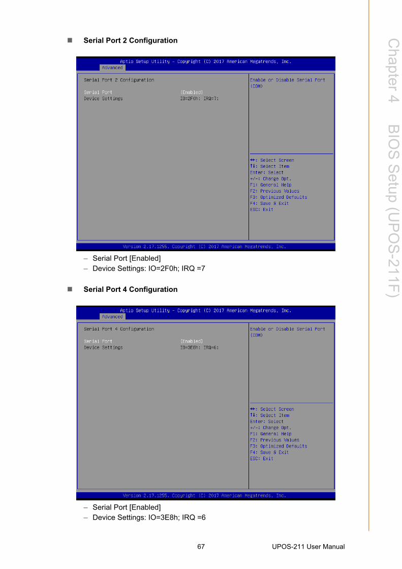
Serial Port 2 Configuration
– Serial Port [Enabled]– Device Settings: IO=2F0h; IRQ =7
Serial Port 4 Configuration
– Serial Port [Enabled]– Device Settings: IO=3E8h; IRQ =6
67 UPOS-211 User Manual

Serial Port 5 Configuration
– Serial Port [Enabled]– Device Settings: IO=2F8h; IRQ =3
Serial Port 6 Configuration
– Serial Port [Enabled]– Device Settings: IO=3F8h; IRQ =4
UPOS-211 User Manual 68

Chapter 4
BIO
S S
etup(U
PO
S-211F
)
Parallel Port Configuration
– Parallel Port [Enabled]To enable or disable Parallel Port
– Device Settings: IO=378h; IRQ =5– Device Mode [EPP-1.9 and SPP Mode]
4.2.2.5 Hardware Monitor.
69 UPOS-211 User Manual

4.2.2.6 S5 RTC Wake Settings
UPOS-211 User Manual 70

Chapter 4
BIO
S S
etup(U
PO
S-211F
)
4.2.2.7 CPU Configuration
71 UPOS-211 User Manual

4.2.2.8 SATA Configuration
SATA Mode Selection [ AHCI ]SATA Speed Support Gen1/Gen2.
Serial-ATA Port 0 [ Enable]Enable or disable SATA Function.
Serial-ATA Port 1 [ Enable]Enable or disable SATA Function.
mSATA Port2 [ Enable]Enable or disable mSATA Function.
UPOS-211 User Manual 72

Chapter 4
BIO
S S
etup(U
PO
S-211F
)
4.2.2.9 CSM Configuration
73 UPOS-211 User Manual

4.2.2.10 USB Configuration
Legacy USB Support [ Enabled ]Enables support for legacy USB. Auto option disables legacy support if no USBdevices are connected.
XHCI Hand-off [ Enabled ] USB Mass Storage Driver Support [ Enabled ] Mass Storage Devices [ Auto ]
Shows USB mass storage device information.
UPOS-211 User Manual 74

Chapter 4
BIO
S S
etup(U
PO
S-211F
)
4.2.3 Chipset Configuration SettingSelect the chipset tab from the BIOS setup screen to enter the Chipset Setup screen.
Users can select any item in the left frame of the screen, such as North Bridge Con-figuration to go to the sub menu for that item. The Chipset Setup screens are shownbelow. The submenus are described on the following pages.
75 UPOS-211 User Manual

4.2.3.1 North Bridge Configuration Setting
Graphics Configuration
UPOS-211 User Manual 76

Chapter 4
BIO
S S
etup(U
PO
S-211F
)
Primary IGFX Boot Display [VBIOS Default]Boot display VBIOS Default /LVDS/CRT/DP++.
Memory Configuration
77 UPOS-211 User Manual

4.2.3.2 PCH-IO Configuration Setting
Restore AC Power Loss [ Power off ]AC power loss power off/Power on.
Wake on LAN [Enable ]Enable or disable Wake on LAN function.
UPOS-211 User Manual 78

Chapter 4
BIO
S S
etup(U
PO
S-211F
)
4.2.4 Security Configuration Setting
Administrator PasswordSelect this option and press <ENTER> to access the sub menu, and then typein the password. Set the Administrator password.
User PasswordSelect this option and press <ENTER> to access the sub menu, and then typein the password. Set the User Password.
79 UPOS-211 User Manual

4.2.5 Boot Configuration
Setup Prompt TimeoutUser the <+> and <-> keys to adjust the number of seconds to wait for setupactivation key.
Bootup NumLock State [ On ]On or Off power on state for the NumLock.
Boot Option #1/#2/#3Choose boot priority from boot device.
UPOS-211 User Manual 80

Chapter 4
BIO
S S
etup(U
PO
S-211F
)
4.2.6 Save & Exit Configuration Setting
Save Changes and ResetWhen users have completed system configuration, select this option to savechanges, exit BIOS setup menu and reboot the computer to take effect of allsystem configuration parameters.
1. Select Exit Saving Changes from the Exit menu and press <Enter>. The following message appears: Save Configuration Changes and Exit Now? [Ok] [Cancel]
2. Select Ok or cancel. Discard Changes and Reset
Select this option to quit Setup without making any permanent changes to thesystem configuration1. Select Reset Discarding Changes from the Exit menuand press <Enter>.
1. The following message appears: Discard Changes and Exit Setup Now? [Ok] [Cancel]
2. Select Ok to discard changes and reset. Discard Changes.Select Discard Changes from the Exit menu and press <Enter>.
Restore DefaultThe BIOS automatically configures all setup items to optimal settings whenusers select this option. Defaults are designed for maximum system perfor-mance, but may not work best for all computer applications. In particular, do notuse the Defaults if the user's computer is experiencing system configurationproblems. Select Restore Defaults from the Exit menu and press <Enter>.
Boot OverrideShows the boot device types on the system.
81 UPOS-211 User Manual

UPOS-211 User Manual 82

www.advantech.comPlease verify specifications before quoting. This guide is intended for referencepurposes only.All product specifications are subject to change without notice.No part of this publication may be reproduced in any form or by any means,such as electronically, by photocopying, recording, or otherwise, without priorwritten permission from the publisher.All brand and product names are trademarks or registered trademarks of theirrespective companies.© Advantech Co., Ltd. 2017