USER MANUAL INSTALLATION INSTRUCTIONS - Premium … · user manual & installation instructions...
51
USER MANUAL & INSTALLATION INSTRUCTIONS FREESTANDING RANGE GAS COOKTOP ELECTRIC OVEN IMPORTANT SAFETY INSTRUCTIONS Carefully read the following important information regarding installation safety and maintenance. Keep these instructions for future reference.
Transcript of USER MANUAL INSTALLATION INSTRUCTIONS - Premium … · user manual & installation instructions...
USER MANUAL&
INSTALLATION INSTRUCTIONS
FREESTANDING RANGEGAS COOKTOP
ELECTRIC OVEN
IMPORTANT SAFETY INSTRUCTIONSCarefully read the following important information regarding
installation safety and maintenance.Keep these instructions for future reference.
Table of ContentsTable of Contents.................................................................................................................2
Safety Requirements ...............................................................................................................3
Ventilation Requirements.......................................................................................................10
Gas Supply Requirements.....................................................................................................13
Type of Gas .......................................................................................................................13
Electrical Requirements.........................................................................................................17
Advance Preparation .............................................................................................................18
Tools and Parts..................................................................................................................18
Range Dimensions.............................................................................................................19
Unpack Range ...................................................................................................................20
Install Leveling Feet and Back Panel .................................................................................20
Install Anti-Tip Bracket .......................................................................................................21
Installation Instructions ..........................................................................................................23
Gas Connection .................................................................................................................23
Liquefied Petroleum (Propane) Gas Conversion................................................................27
Electrical Connection .........................................................................................................32
Surface Cooking ....................................................................................................................35
Flame Size .........................................................................................................................35
Proper Burner Adjustments................................................................................................35
Location of the Burners ......................................................................................................36
Placement of Burner Heads and Caps...............................................................................36
Surface Cooking Utensils...................................................................................................37
Setting Surface Controls ....................................................................................................38
Oven Cooking........................................................................................................................39
Setting Oven Clock and Timer ...........................................................................................39
Setting Oven Controls ........................................................................................................40
Cooking Instructions...........................................................................................................43
Care and Cleaning.................................................................................................................44
Solutions to Common Problems ............................................................................................48
Safety Requirements
IMPORTANT SAFETY NOTICE READ ALL INSTRUCTION BEFORE INSTALLING AND OPERATING THIS APPLIANCE
We have provided many important safety messages in this manual and on your appliance. Always
read and obey all safety messages.
This is the safety alert symbol.
This symbol alerts you to potential hazards that can kill or hurt you and others.
All safety messages will follow the safety alert symbol and either the word “DANGER” or “WARNING.”
These words mean:
You can be killed or seriously injured if you don't immediately follow instructions.
You can be killed or seriously injured if you don't follow instructions. All safety messages will tell you what the potential hazard is, how to reduce the chance of injury, and
what can happen if the instructions are not followed.
• Remove all tape and packaging before using the appliance. Never allow children to play with
packaging material. Do not remove the model/serial plate attached to the appliance.
• Be sure your appliance is properly installed and grounded by a QUALIFIED TECHNICIAN in
accordance with the National Fuel Gas Code ANSI Z223.1—latest edition in the United States, or in
Canada CAN/CGA B149.1, and CAN/CGA B149.2, and the National Electrical Code ANSI/NFPA No.
70—latest edition in United States, or in Canada CSA Standard C22.1, Canadian Electrical Code,
Part 1, and local code requirements. Install only as per installation instructions provided in the
literature package for this appliance.
If the information in this manual is not followed exactly, a fire or explosion may result causing property
damage, personal injury or death.
• FOR YOUR SAFETY: - Do not store or use gasoline or other flammable vapors and liquids in the vicinity of this or any
other appliance.
• WHAT TO DO IF YOU SMELL GAS: - Do not try to light any appliance.
- Do not touch any electrical switch; do not use any phone in your building.
- Immediately call your gas supplier from a neighbor’s phone. Follow the gas supplier’s
instructions.
- If you cannot reach your gas supplier, call the fire department.
− Gas leaks cannot always be detected by smell.
− Gas suppliers recommend that you use a gas detector approved by UL or CSA.
− For more information, contact your gas supplier.
− If a gas leak is detected, follow the “What to do if you smell gas” instructions.
In the State of Massachusetts, the following installation instructions apply:
− Installations and repairs must be performed by a qualified or licensed contractor, plumber, or
gasfitter qualified or licensed by the State of Massachusetts.
− If using a ball valve, it shall be a T-handle type.
− A flexible gas connector, when used, must not exceed 3 feet.
• Installation and service must be performed by a qualified installer, servicer or the gas supplier.
Ask your dealer to recommend a qualified technician and an authorized repair service. Know how to
shut off gas supply at the meter and disconnect the electrical power to the appliance at the circuit
breaker or fuse box in case of an emergency.
• Do not repair or replace any part of the appliance unless specifically recommended in the
manuals. All other servicing should be done only by a qualified technician. This may reduce the risk
of personal injury and damage to the appliance.
• Proper Installation – The range, when installed, must be electrically grounded in accordance
with local codes or, in the absence of local codes, with the National Electrical Code, ANSI/NFPA 70.
In Canada, the range must be electrically grounded in accordance with Canadian Electrical Code. Be
sure the range is properly installed and grounded by a qualified technician.
• Disconnect power before servicing.
• Never modify or alter the construction of the appliance by removing panels, wire covers or any
other part of the product.
• Injuries may result from the misuse of appliance doors or drawers such as stepping, leaning, or
sitting on the doors or drawers.
• Overhead range hoods, which operate by blowing a downward air flow on to a range, shall not
be used in conjunction with gas ranges other than when the hood and range have been designed,
tested and listed by an independent test laboratory for use in combination with each other.
• Ensure that the room is well ventilated by keeping the air intakes open and in good working
order or by installing an extractor hood with discharge pipe. If the appliance is used intensively for a
long time the effectiveness of the ventilation will have to be increased, for example by opening a
window or increasing the power of any electric extractor fan.
• Flammable materials should not be stored on the appliance or near surface units. This includes
paper, plastic and cloth items, such as cookbooks, plastic ware and towels, as well as flammable
liquids. Do not store explosives, such as aerosol cans, on or near the appliance. Flammable
materials may explode and result in fire or property damage.
• Maintenance – Keep range area clear and free from combustible materials, gasoline, and other
flammable vapors and liquids.
• Storage in or on the Range – Flammable materials should not be stored in an oven or near
surface units.
Do not store items of interest to children in the cabinets above the appliance or on the backguard of
a range. Children should not be left alone or unattended in the area where appliance is in use. Do
not allow children to climb or play around the appliance. They should never be allowed to sit or stand
on any part of the appliance. Children climbing on the appliance to reach items could be seriously
injured.
• DO NOT TOUCH THE COOKING SURFACE, THE BURNERS, GRATES OR ANY AREAS NEAR THEM. Surface burners or appliance may be hot even though flames are not visible. Areas
near surface burners or appliance may become hot enough to cause burns. During and after use, do
not touch, or let clothing or other flammable materials touch these areas until they have had sufficient
time to cool.
• Do not wear loose-fitting or hanging garments while using the appliance. Do not let clothing or
other flammable materials contact hot surfaces.
• Smother grease fires with a pan lid, or use baking soda, a dry chemical or foam-type
extinguisher.
• Use an extinguisher ONLY if:
- You know you have a Class A, B, C extinguisher, and you already know how to operate it.
- The fire is small and contained in the area where it is started.
- The fire department is being called.
- You can fight the fire with your back to an exit.
• When heating fat or grease, watch it closely. Fat or grease may catch fire if allowed to become
too hot.
• Use only dry potholders. Moist or damp potholders on hot surfaces may result in burns from
steam. Do not let potholders touch hot heating elements, the flame or burners. Do not use a towel or
other bulky cloth instead of a potholder.
• Do not heat unopened food containers. Buildup of pressure may cause the container to burst
and result in injury.
• Stepping, leaning or sitting on this appliance can result in serious injuries and also cause
damage to the appliance.
• Never use this appliance as a space heater to heat or warm the room. Doing so may result in
carbon monoxide poisoning and overheating of the oven.
• Know which knob controls which surface burner. Visually check that the burner has lit. Then
adjust the flame so it does not extend beyond the edge of the utensil.
• Clean the appliance regularly to keep all parts free of grease that could catch fire. Exhaust fan
ventilation hoods and grease filters should be kept clean. Do not allow grease to accumulate on hood
or filter. Greasy deposits in the fan could catch fire. When cooking food turn the hood, fan on. Refer
to hood manufacturer’s instructions for cleaning.
• Utensil handles should be turned inward and not extend over adjacent surface burners. To
reduce the risk of burns, ignition of flammable materials, and spillage due to unintentional contact with
the utensil, the handle of the utensil should be positioned so that it is turned inward, and does not
extend over adjacent surface burners.
• Never leave surface burners unattended at high heat settings. Boil overs cause smoke and
greasy spillovers that may ignite, or a pan that has boiled dry may melt.
• Do not use aluminum foil to line any part of the appliance. Use aluminum foil only to cover food
during cooking. Improper installation of these liners may result in risk of electric shock or fire.
• Only certain types of glass, glass/ceramic, ceramic, earthenware, or other glazed utensils are
suitable for appliance service without breaking due to the sudden change in temperature. Check the
manufacturer’s recommendations for appliance use.
• Do not use decorative surface burner covers. If a burner is accidentally turned on, the
decorative cover will become hot and possibly melt. You will not be able to see that the burner is on.
Burns will occur if the hot covers are touched. Damage may also be done to the range or burners
because the covers may cause overheating. Air will be blocked from the burner and cause
combustion problems.
• Always use proper flame size. Adjust flame size so it does not extend beyond the edge of the
utensil. The use of undersized utensils will expose a portion of the burner flame to direct contact and
may result in ignition of clothing. Proper relationship of utensil to flame will also improve efficiency.
• Top burner flame size should be adjusted so it does not extend beyond the edge of the cooking
utensil.
• Use the proper pan sizes. This appliance is equipped with surface units of different sizes. Select
utensils having flat bottoms large enough to cover the surface unit. The use of undersized utensils
will expose a portion of the surface heating unit to direct contact and may result in ignition of clothing.
Proper relationship of utensil to the surface unit will also improve efficiency.
• Do not use stove top grills on your gas appliance. If you use a stove top grill on a sealed gas
burner, it will cause incomplete combustion and can result in exposure to carbon monoxide levels
above allowable current standards. This can be hazardous to your health.
TO REDUCE THE RISK OF TIPPING OF THE RANGE, THE RANGE MUST BE SECURED BY
PROPERLY INSTALLED ANTI-TIP DEVICES. TO CHECK IF THE DEVICES ARE INSTALLED
PROPERLY, SLIDE RANGE FORWARD, LOOK FOR ANTI-TIP BRACKET SECURELY ATTACHED
TO FLOOR OR WALL, AND SLIDE RANGE BACK SO REAR RANGE FOOT IS UNDER ANTI-TIP
BRACKET.
• The range will not tip during normal use. However, the range can tip if you apply too much force
or weight to the open door without having the anti-tip bracket fastened down properly.
TIP OVER HAZARD
A child or adult can tip the range and be killed. Connect anti-tip bracket to rear range foot. Reconnect the anti-tip bracket, if the range is moved. See the installation instructions for details. Failure to follow these instructions can result in death or serious burns to children and adults.
Ventilation Requirements
The range should have proper ventilation in order to keep the unit operating properly and maintain the
temperature of immediate surroundings within safe limits. Check your local building codes as they
may vary from the general rules outlined in this guide. It is recommended that a hood be installed
above the range that is rated no less than 400 CFM. This will provide adequate ventilation for this
range. Mounting distance of your ventilation is outlined by the manufacturer of your hood and is
dependent on the total BTU output of your range.
• Observe all governing codes and ordinances. Do not obstruct flow of combustion and ventilation
air.
• It is the installer’s responsibility to comply with installation clearances specified on the
model/serial rating plate.
• For proper operation of a gas appliance, the air necessary for the combustion of the gas must be
able to flow into the room naturally. The air must flow into the room directly through openings in the
outside walls. These openings must have an unobstructed cross-section not less than 2m3/h for each
kw of power (see total power in kw on the appliance).
• This opening must be constructed so that it will not be obstructed from inside or outside, and
not be constructed close to the floor. The opening is recommended to be on the side opposite to that
on which the flue gases are discharged.
• The range should be located for convenient use in the kitchen.
• Recessed installations must provide complete enclosure of the sides and rear of the range.
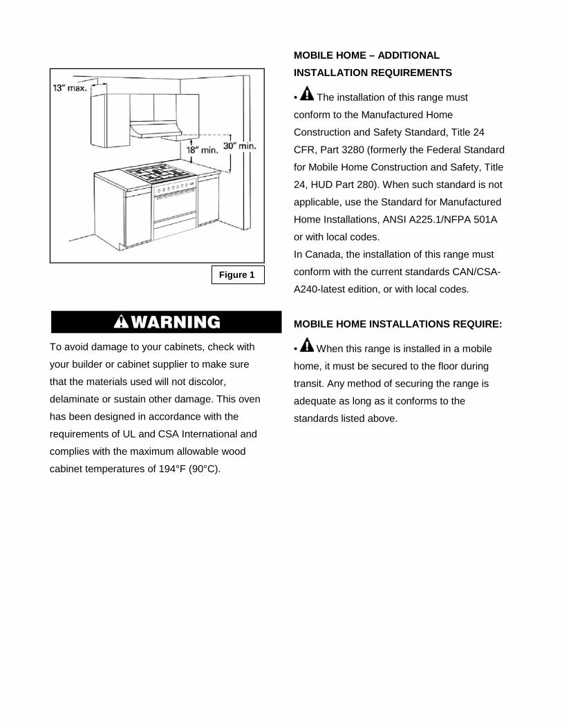
• To eliminate the risk of burns or fire by
reaching over heated surface units, cabinet
storage space located above the surface units
should be avoided. If cabinet storage is to be
provided, the risk can be reduced by installing
a range hood or microwave hood combination
with minimum 400 CFM that projects
horizontally a minimum of 5" (12.7 cm) beyond
the bottom of the cabinets. (See Figure 1)
• If a range hood is installed above the
appliance, maintain a 30” minimum clearance
between cooking surface and bottom of range
hood. The range hood must be connected
directly to flues or to the outside. (See Figure
1)
• Avoid placing cabinetry directly above
the appliance when possible. If cabinetry is
used above the cooking surface, use cabinets
no more than 13″ deep. Make sure the wall
coverings, countertop and cabinets around the
appliance can withstand heat up to 200º F
(93°C) generated by the appliance. (See
Figure 1)
• Cabinet opening dimensions that are
shown must be used. Given dimensions are
minimum clearances. (See Figure 1)
• Working areas adjacent to the range
should have 18″ minimum clearance between
countertop and cabinet bottom. (See Figure 1)
• All openings in the wall or floor where
range is to be installed must be sealed.
• Contact a qualified floor covering installer
to check that the floor covering can withstand
at least 200°F (93°C).
• Use an insulated pad or ¼" (0.64 cm)
plywood under range if installing range over
carpeting.
• The floor anti-tip bracket must be
installed. To install the anti-tip bracket shipped
with the range, see “Install Anti-Tip Bracket”
section.
• Grounded electrical supply is required.
See “Electrical Requirements” section.
• Proper gas supply connection must be
available. See “Gas Supply Requirements”
section.
To avoid damage to your cabinets, check with
your builder or cabinet supplier to make sure
that the materials used will not discolor,
delaminate or sustain other damage. This oven
has been designed in accordance with the
requirements of UL and CSA International and
complies with the maximum allowable wood
cabinet temperatures of 194°F (90°C).
MOBILE HOME – ADDITIONAL INSTALLATION REQUIREMENTS
• The installation of this range must
conform to the Manufactured Home
Construction and Safety Standard, Title 24
CFR, Part 3280 (formerly the Federal Standard
for Mobile Home Construction and Safety, Title
24, HUD Part 280). When such standard is not
applicable, use the Standard for Manufactured
Home Installations, ANSI A225.1/NFPA 501A
or with local codes.
In Canada, the installation of this range must
conform with the current standards CAN/CSA-
A240-latest edition, or with local codes.
MOBILE HOME INSTALLATIONS REQUIRE:
• When this range is installed in a mobile
home, it must be secured to the floor during
transit. Any method of securing the range is
adequate as long as it conforms to the
standards listed above.
Figure 1
Gas Supply Requirements
EXPLOSION HAZARD
Use a new CSA International approved gas supply line. Install a shut-off valve. Securely tighten all gas connections. If connected to LP, have a qualified person make sure gas pressure does not exceed 14" (36 cm) water column. Examples of a qualified person include:
− Licensed heating personnel
− Authorized gas company personnel
− Authorized service personnel Failure to do so can result in death, explosion, or fire.
• Observe all governing codes and
ordinances.
IMPORTANT: This installation must conform
with all local codes and ordinances. In the
absence of local codes, installation must
conform with American National Standard,
National Fuel Gas Code ANSI Z223.1 - latest
edition or CAN/CGA B149 - latest edition.
IMPORTANT: Leak testing of the range must
be conducted according to the manufacturer’s
instructions.
Type of Gas NATURAL GAS:
− This range is designed for use with
Natural gas or, after proper conversion,
for use with LP gas.
− This range is factory set for use with
Natural gas. The model/serial rating
plate has information on the types of
gas that can be used. If the types of
gas listed do not include the type of gas
available, check with the local gas
supplier.
LP GAS CONVERSION:
− Conversion must be done by a qualified
service technician.
− No attempt shall be made to convert
the appliance from the gas specified on
the model/serial rating plate for use
with a different gas without consulting
the serving gas supplier.
GAS SUPPLY LINE:
− Provide a gas supply line of ¾" (1.9
cm) rigid pipe to the range location. A
smaller size pipe on longer runs may
result in insufficient gas supply. Pipe-
joint compounds that resist the action
of LP gas must be used. Do not use
TEFLON®† tape. With LP gas, piping
or tubing size must be ½" (1.3 cm)
minimum. Usually, LP gas suppliers
determine the size and materials used
in the system.
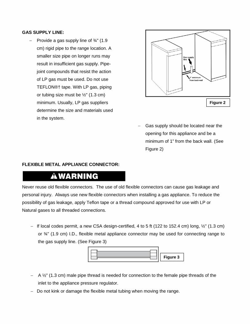
− Gas supply should be located near the
opening for this appliance and be a
minimum of 1” from the back wall. (See
Figure 2)
FLEXIBLE METAL APPLIANCE CONNECTOR:
Never reuse old flexible connectors. The use of old flexible connectors can cause gas leakage and
personal injury. Always use new flexible connectors when installing a gas appliance. To reduce the
possibility of gas leakage, apply Teflon tape or a thread compound approved for use with LP or
Natural gases to all threaded connections.
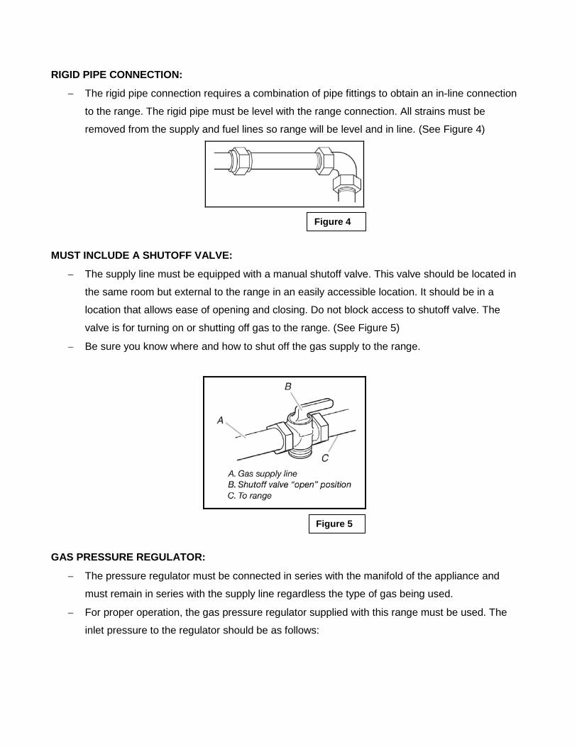
− If local codes permit, a new CSA design-certified, 4 to 5 ft (122 to 152.4 cm) long, ½" (1.3 cm)
or ¾" (1.9 cm) I.D., flexible metal appliance connector may be used for connecting range to
the gas supply line. (See Figure 3)
− A ½" (1.3 cm) male pipe thread is needed for connection to the female pipe threads of the
inlet to the appliance pressure regulator.
− Do not kink or damage the flexible metal tubing when moving the range.
Figure 3
Figure 2
RIGID PIPE CONNECTION:
− The rigid pipe connection requires a combination of pipe fittings to obtain an in-line connection
to the range. The rigid pipe must be level with the range connection. All strains must be
removed from the supply and fuel lines so range will be level and in line. (See Figure 4)
MUST INCLUDE A SHUTOFF VALVE:
− The supply line must be equipped with a manual shutoff valve. This valve should be located in
the same room but external to the range in an easily accessible location. It should be in a
location that allows ease of opening and closing. Do not block access to shutoff valve. The
valve is for turning on or shutting off gas to the range. (See Figure 5)
− Be sure you know where and how to shut off the gas supply to the range.
GAS PRESSURE REGULATOR:
− The pressure regulator must be connected in series with the manifold of the appliance and
must remain in series with the supply line regardless the type of gas being used.
− For proper operation, the gas pressure regulator supplied with this range must be used. The
inlet pressure to the regulator should be as follows:
Figure 4
Figure 5
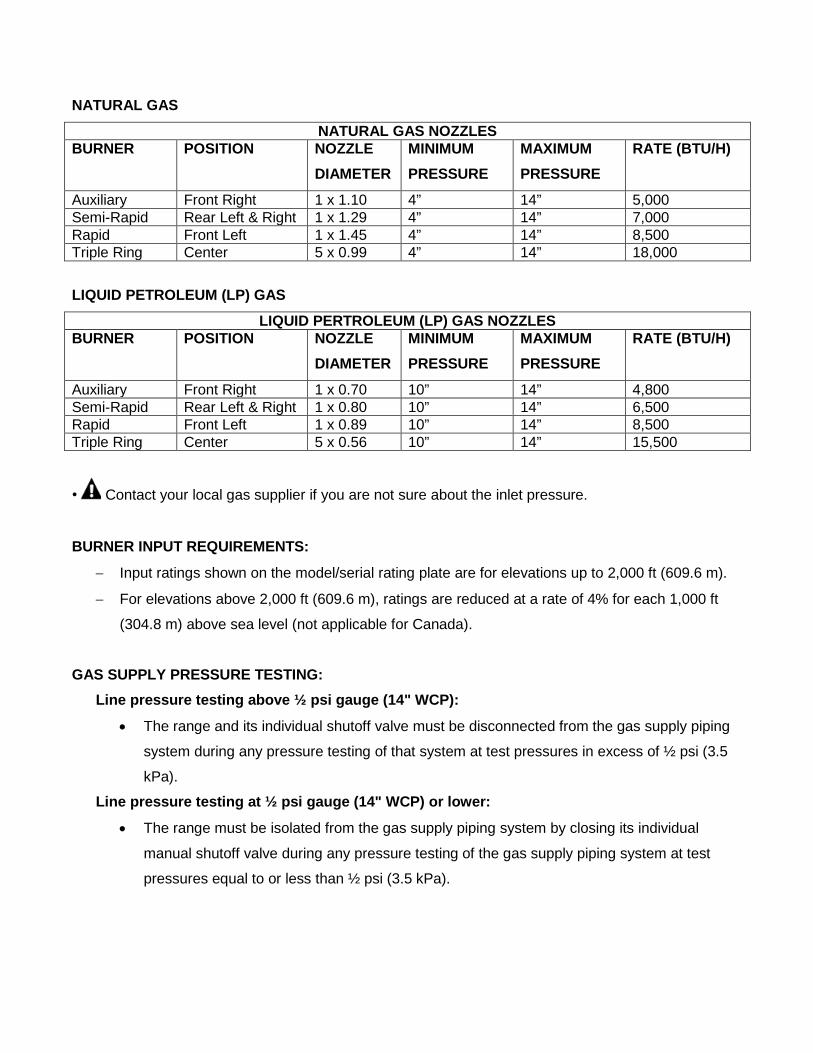
NATURAL GAS
NATURAL GAS NOZZLES BURNER POSITION NOZZLE
DIAMETER MINIMUM PRESSURE
MAXIMUM PRESSURE
RATE (BTU/H)
Auxiliary Front Right 1 x 1.10 4” 14” 5,000 Semi-Rapid Rear Left & Right 1 x 1.29 4” 14” 7,000 Rapid Front Left 1 x 1.45 4” 14” 8,500 Triple Ring Center 5 x 0.99 4” 14” 18,000
LIQUID PETROLEUM (LP) GAS
LIQUID PERTROLEUM (LP) GAS NOZZLES BURNER POSITION NOZZLE
DIAMETER MINIMUM PRESSURE
MAXIMUM PRESSURE
RATE (BTU/H)
Auxiliary Front Right 1 x 0.70 10” 14” 4,800 Semi-Rapid Rear Left & Right 1 x 0.80 10” 14” 6,500 Rapid Front Left 1 x 0.89 10” 14” 8,500 Triple Ring Center 5 x 0.56 10” 14” 15,500
• Contact your local gas supplier if you are not sure about the inlet pressure.
BURNER INPUT REQUIREMENTS:
− Input ratings shown on the model/serial rating plate are for elevations up to 2,000 ft (609.6 m).
− For elevations above 2,000 ft (609.6 m), ratings are reduced at a rate of 4% for each 1,000 ft
(304.8 m) above sea level (not applicable for Canada).
GAS SUPPLY PRESSURE TESTING: Line pressure testing above ½ psi gauge (14" WCP):
• The range and its individual shutoff valve must be disconnected from the gas supply piping
system during any pressure testing of that system at test pressures in excess of ½ psi (3.5
kPa).
Line pressure testing at ½ psi gauge (14" WCP) or lower:
• The range must be isolated from the gas supply piping system by closing its individual
manual shutoff valve during any pressure testing of the gas supply piping system at test
pressures equal to or less than ½ psi (3.5 kPa).
Electrical Requirements
Electrical Shock Hazard Do not use an extension cord. Failure to follow these instructions can result in death, fire, or electrical shock.
• Any additions, changes or conversions
required in order for this appliance to
satisfactorily meet the application needs must
be made by a qualified service technician in
accordance with the manufacturer’s
instructions and all codes and requirements of
the authority having jurisdiction. Failure to
follow the instructions could result in serious
injury or property damage. The qualified
agency performing this work assumes
responsibility for the conversion.
• This appliance is not supplied with a plug.
If you wish to install this appliance with a plug,
it must installed by a qualified service
technician. The plug must be a 4-prong, 3-
phase plug that is designed specifically for
freestanding ranges.
• This appliance can be installed directly to
the main (without a plug). To do so, follow
instructions in the “Electrical Connection”
section. If you wish to install this appliance
directly to the main (without a plug), it must be
installed by a qualified service technician.
• DO NOT operate this appliance using a
2-prong adapter or an extension cord. If a 2-
prong wall receptacle is the only available
outlet, it is the personal responsibility of the
consumer to have it replaced with a properly
grounded 4-prong wall receptacle installed by
a qualified electrician.
• Severe shock, or damage to the range
may occur if the range is not installed by a
qualified installer or electrician.
• This appliance features a pilotless
electric ignition for energy savings and
reliability. It operates on a 220-240V/50-60Hz - 35 Amp power supply.
• A separate circuit, protected by a 15 amp
time delay fuse or circuit breaker, is required.
• For personal safety, the appliance must
be properly grounded.
• See the “Installation Instructions” packaged with this appliance for complete
installation and grounding instructions.
Advance PreparationTools and Parts Gather the required tools and parts before starting installation.
Read and follow the instructions provided with any tools listed here.
■ Tape measure
■ Phillips screwdriver
■ Flat blade screwdriver
■ 1/8” flat blade screwdriver
■ Level
■ Hand or electric drill
■ Wrench or pliers
■ Pipe wrench
■ 1 5/16" combination wrench
■ 1/8” (3.2 mm) drill bit (for wood floors)
■ Marker or pencil
■ Pipe-joint compound resistant to LP gas
■ 3/16” (4.8 mm) carbide-tipped masonry drill
bit (for concrete/ceramic floors)
■ Noncorrosive leak-detection solution
FOR LP/NATURAL GAS CONVERSIONS: ■ 1/2" Combination wrench
■ 1/4" (6 mm) nut driver
■ 9/32" (7 mm) nut driver
■ Masking tape
PARTS SUPPLIED: Check that all parts are included.
■ LP/Natural Gas Conversion Kit
■ 5 - Burner caps
■ 3 - Burner grates
■ 3 - Oven racks
■ 1 Anti-tip brackets
■ 2 plastic anchors
■ 2 screws
The anti-tip bracket must be securely mounted
to the floor. Thickness of flooring may require
longer screws to anchor bracket to subfloor.
PARTS NEEDED Check local codes and consult gas supplier.
Check existing gas supply and electrical
supply. See “Electrical Requirements” and
“Gas Supply Requirements” sections.
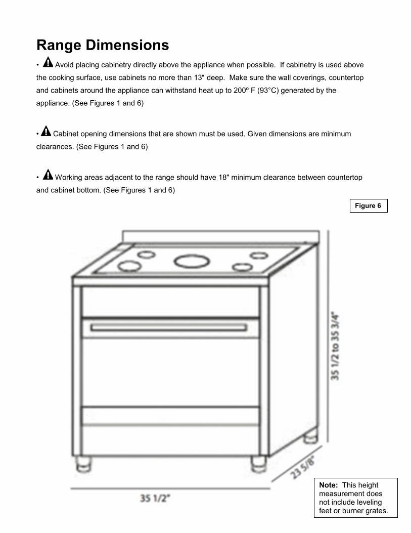
Range Dimensions• Avoid placing cabinetry directly above the appliance when possible. If cabinetry is used above
the cooking surface, use cabinets no more than 13″ deep. Make sure the wall coverings, countertop
and cabinets around the appliance can withstand heat up to 200º F (93°C) generated by the
appliance. (See Figures 1 and 6)
• Cabinet opening dimensions that are shown must be used. Given dimensions are minimum
clearances. (See Figures 1 and 6)
• Working areas adjacent to the range should have 18″ minimum clearance between countertop
and cabinet bottom. (See Figures 1 and 6)
Figure 6
Note: This height measurement does not include leveling feet or burner grates.
Unpack Range Install Leveling Feet and Back Panel
Excessive Weight Hazard Tip Over Hazard A child or adult can tip the range and be killed. Use two or more people to move and install range. Failure to follow these instructions can result in death or serious burns to children and adults.
1. Remove shipping materials from the
range. DO NOT remove protective film
covering the appliance. DO NOT
remove tape securing the drawer.
2. Remove oven racks and parts package
from inside oven.
3. Place range on its back; take four (4) L-
shaped cardboard corners from the
carton. Stack one cardboard corner on
top of another. Repeat with the other 2
corners.
4. Place the four (4) L-shaped cardboard
corners lengthwise on the floor behind
the range to support the range when it
is laid on its back.
5. Using 2 or more people firmly grasp the
range and gently lay it on its back on
the cardboard corners.
6. Install the leveling feet one at a time.
The leveling feet can be found in one of
the boxes that was inside the oven.
7. Place cardboard or hardboard in front
of range. Using 2 or more people,
stand range back up onto cardboard or
hardboard.
8. Remove the protective film covering the
appliance. Remove tape securing the
drawer.
9. The stainless steel back panel can now
be installed. Place panel into the
grooves on the top rear of the range.
Then affix the panel to the range using
the screws provided.
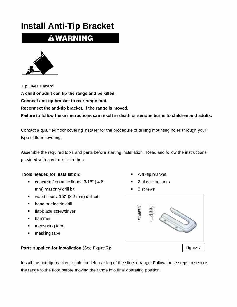
Install Anti-Tip Bracket
Tip Over Hazard A child or adult can tip the range and be killed. Connect anti-tip bracket to rear range foot. Reconnect the anti-tip bracket, if the range is moved. Failure to follow these instructions can result in death or serious burns to children and adults.
Contact a qualified floor covering installer for the procedure of drilling mounting holes through your
type of floor covering.
Assemble the required tools and parts before starting installation. Read and follow the instructions
provided with any tools listed here.
Tools needed for installation: concrete / ceramic floors: 3/16" ( 4.6
mm) masonry drill bit
wood floors: 1/8" (3.2 mm) drill bit
hand or electric drill
flat-blade screwdriver
hammer
measuring tape
masking tape
Parts supplied for installation (See Figure 7):
Anti-tip bracket
2 plastic anchors
2 screws
Install the anti-tip bracket to hold the left rear leg of the slide-in range. Follow these steps to secure
the range to the floor before moving the range into final operating position.
Figure 7
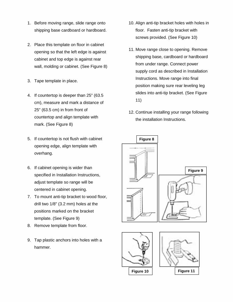
1. Before moving range, slide range onto
shipping base cardboard or hardboard.
2. Place this template on floor in cabinet
opening so that the left edge is against
cabinet and top edge is against rear
wall, molding or cabinet. (See Figure 8)
3. Tape template in place.
4. If countertop is deeper than 25" (63.5
cm), measure and mark a distance of
25" (63.5 cm) in from front of
countertop and align template with
mark. (See Figure 8)
5. If countertop is not flush with cabinet
opening edge, align template with
overhang.
6. If cabinet opening is wider than
specified in Installation Instructions,
adjust template so range will be
centered in cabinet opening.
7. To mount anti-tip bracket to wood floor,
drill two 1/8" (3.2 mm) holes at the
positions marked on the bracket
template. (See Figure 9)
8. Remove template from floor.
9. Tap plastic anchors into holes with a
hammer.
10. Align anti-tip bracket holes with holes in
floor. Fasten anti-tip bracket with
screws provided. (See Figure 10)
11. Move range close to opening. Remove
shipping base, cardboard or hardboard
from under range. Connect power
supply cord as described in Installation
Instructions. Move range into final
position making sure rear leveling leg
slides into anti-tip bracket. (See Figure
11)
12. Continue installing your range following
the installation Instructions.
Figure 8
Figure 9
Figure 10 Figure 11
Installation Instructions
Gas Connection
Explosion Hazard Use a new CSA International approved gas supply line. Install a shut-off valve. Securely tighten all gas connections. If connected to LP, have a qualified person make sure gas pressure does not exceed 14" (36 cm) water column. Examples of a qualified person include: licensed heating personnel, authorized gas company personnel, and authorized service personnel. Failure to do so can result in death, explosion, or fire.
This appliance is outfitted from the factory to be used with ONLY one type of gas. This range is to be
connected with gas supply line. The gas connection is a male ½” BSP and is located roughly 2 ¼”
from the right and 22” from the ground. The hose needs to be free of kinks or other deformation that
would inhibit its ability to supply gas to the unit or susceptible to a gas leak. Line should also be free
from contact with a moving part such as a drawer, so that it does not become obstructed or damaged.
INSTALLING THE PRESSURE REGULATOR • This appliance is set for natural gas and is designed to operate at 5” water column pressure. The
gas supply is required to provide a minimum of 4” to a maximum of 14” water column pressure to the
appliance regulator.
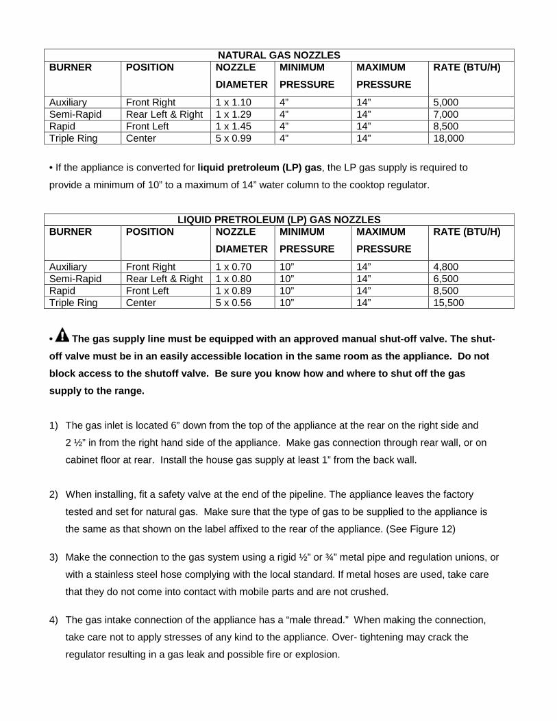
NATURAL GAS NOZZLES BURNER POSITION NOZZLE
DIAMETER MINIMUM PRESSURE
MAXIMUM PRESSURE
RATE (BTU/H)
Auxiliary Front Right 1 x 1.10 4” 14” 5,000 Semi-Rapid Rear Left & Right 1 x 1.29 4” 14” 7,000 Rapid Front Left 1 x 1.45 4” 14” 8,500 Triple Ring Center 5 x 0.99 4” 14” 18,000
• If the appliance is converted for liquid pretroleum (LP) gas, the LP gas supply is required to
provide a minimum of 10” to a maximum of 14” water column to the cooktop regulator.
LIQUID PRETROLEUM (LP) GAS NOZZLES BURNER POSITION NOZZLE
DIAMETER MINIMUM PRESSURE
MAXIMUM PRESSURE
RATE (BTU/H)
Auxiliary Front Right 1 x 0.70 10” 14” 4,800 Semi-Rapid Rear Left & Right 1 x 0.80 10” 14” 6,500 Rapid Front Left 1 x 0.89 10” 14” 8,500 Triple Ring Center 5 x 0.56 10” 14” 15,500
• The gas supply line must be equipped with an approved manual shut-off valve. The shut-off valve must be in an easily accessible location in the same room as the appliance. Do not block access to the shutoff valve. Be sure you know how and where to shut off the gas supply to the range. 1) The gas inlet is located 6” down from the top of the appliance at the rear on the right side and
2 ½” in from the right hand side of the appliance. Make gas connection through rear wall, or on
cabinet floor at rear. Install the house gas supply at least 1” from the back wall.
2) When installing, fit a safety valve at the end of the pipeline. The appliance leaves the factory
tested and set for natural gas. Make sure that the type of gas to be supplied to the appliance is
the same as that shown on the label affixed to the rear of the appliance. (See Figure 12)
3) Make the connection to the gas system using a rigid ½” or ¾” metal pipe and regulation unions, or
with a stainless steel hose complying with the local standard. If metal hoses are used, take care
that they do not come into contact with mobile parts and are not crushed.
4) The gas intake connection of the appliance has a “male thread.” When making the connection,
take care not to apply stresses of any kind to the appliance. Over- tightening may crack the
regulator resulting in a gas leak and possible fire or explosion.
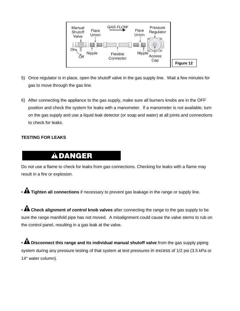
5) Once regulator is in place, open the shutoff valve in the gas supply line. Wait a few minutes for
gas to move through the gas line.
6) After connecting the appliance to the gas supply, make sure all burners knobs are in the OFF
position and check the system for leaks with a manometer. If a manometer is not available, turn
on the gas supply and use a liquid leak detector (or soap and water) at all joints and connections
to check for leaks.
TESTING FOR LEAKS
Do not use a flame to check for leaks from gas connections. Checking for leaks with a flame may
result in a fire or explosion.
• Tighten all connections if necessary to prevent gas leakage in the range or supply line.
• Check alignment of control knob valves after connecting the range to the gas supply to be
sure the range manifold pipe has not moved. A misalignment could cause the valve stems to rub on
the control panel, resulting in a gas leak at the valve.
• Disconnect this range and its individual manual shutoff valve from the gas supply piping
system during any pressure testing of that system at test pressures in excess of 1/2 psi (3.5 kPa or
14" water column).
Figure 12
• Isolate the range from the gas supply piping system by closing its individual manual shutoff
valve during any pressure testing of the gas supply piping system at test pressures equal to or less
than 1/2 psi (3.5 kPa or 14" water column).
ASSEMBLY OF THE BURNERS The electrode of the electronic ignition system is positioned above the surface of the burner base. Do
not remove a burner cap or touch the electrode of a burner while another is turned on. Damage or
electrical shock may occur.
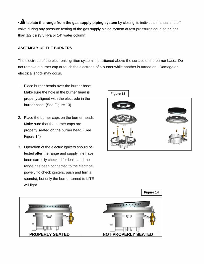
1. Place burner heads over the burner base.
Make sure the hole in the burner head is
properly aligned with the electrode in the
burner base. (See Figure 13)
2. Place the burner caps on the burner heads.
Make sure that the burner caps are
properly seated on the burner head. (See
Figure 14)
3. Operation of the electric igniters should be
tested after the range and supply line have
been carefully checked for leaks and the
range has been connected to the electrical
power. To check igniters, push and turn a
sounds), but only the burner turned to LITE
will light.
Figure 13
Figure 14
Liquefied Petroleum (Propane) Gas Conversion
Failure to make the appropriate conversion can result in serious personal injury and property damage.
The conversion must be performed by a qualified service technician in accordance with the kit instructions and all local codes and requirements. Failure to follow instructions could result in serious injury or property damage. The qualified agency performing this work assumes responsibility for the conversion.
This appliance can be used with Natural Gas or LP/Propane Gas. It is shipped from the factory for
use with Natural Gas. A kit for converting to LP gas is supplied with your appliance. The kit is
marked "FOR LP/PROPANE GAS CONVERSION".
When the range is converted for Liquid Petroleum (LP) Gas, the LP gas supply is required to provide
a minimum of 10” to a maximum of 14” water column to the range regulator.
A. ADJUST THE REGULATOR
− Disconnect all electrical power at the main circuit breaker or fuse box.
− Shut off the gas supply to the appliance by closing the manual shut-off valve.
− Adjust the pressure regulator by doing the following:
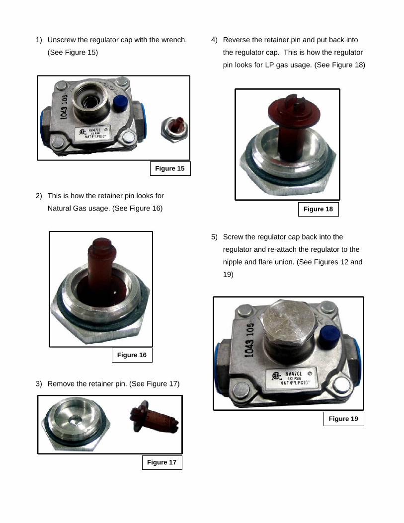
1) Unscrew the regulator cap with the wrench.
(See Figure 15)
2) This is how the retainer pin looks for
Natural Gas usage. (See Figure 16)
3) Remove the retainer pin. (See Figure 17)
4) Reverse the retainer pin and put back into
the regulator cap. This is how the regulator
pin looks for LP gas usage. (See Figure 18)
5) Screw the regulator cap back into the
regulator and re-attach the regulator to the
nipple and flare union. (See Figures 12 and
19)
Figure 15
Figure 16
Figure 17
Figure 18
Figure 19
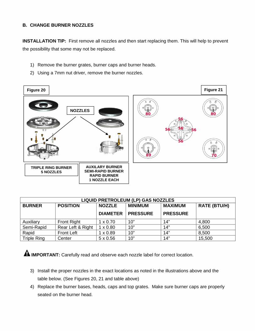
B. CHANGE BURNER NOZZLES INSTALLATION TIP: First remove all nozzles and then start replacing them. This will help to prevent
the possibility that some may not be replaced.
1) Remove the burner grates, burner caps and burner heads.
2) Using a 7mm nut driver, remove the burner nozzles.
LIQUID PRETROLEUM (LP) GAS NOZZLES BURNER POSITION NOZZLE
DIAMETER MINIMUM PRESSURE
MAXIMUM PRESSURE
RATE (BTU/H)
Auxiliary Front Right 1 x 0.70 10” 14” 4,800 Semi-Rapid Rear Left & Right 1 x 0.80 10” 14” 6,500 Rapid Front Left 1 x 0.89 10” 14” 8,500 Triple Ring Center 5 x 0.56 10” 14” 15,500
IMPORTANT: Carefully read and observe each nozzle label for correct location.
3) Install the proper nozzles in the exact locations as noted in the illustrations above and the
table below. (See Figures 20, 21 and table above)
4) Replace the burner bases, heads, caps and top grates. Make sure burner caps are properly
seated on the burner head.
Figure 20
TRIPLE RING BURNER 5 NOZZLES
AUXILARY BURNER SEMI-RAPID BURNER
RAPID BURNER 1 NOZZLE EACH
NOZZLES
Figure 21
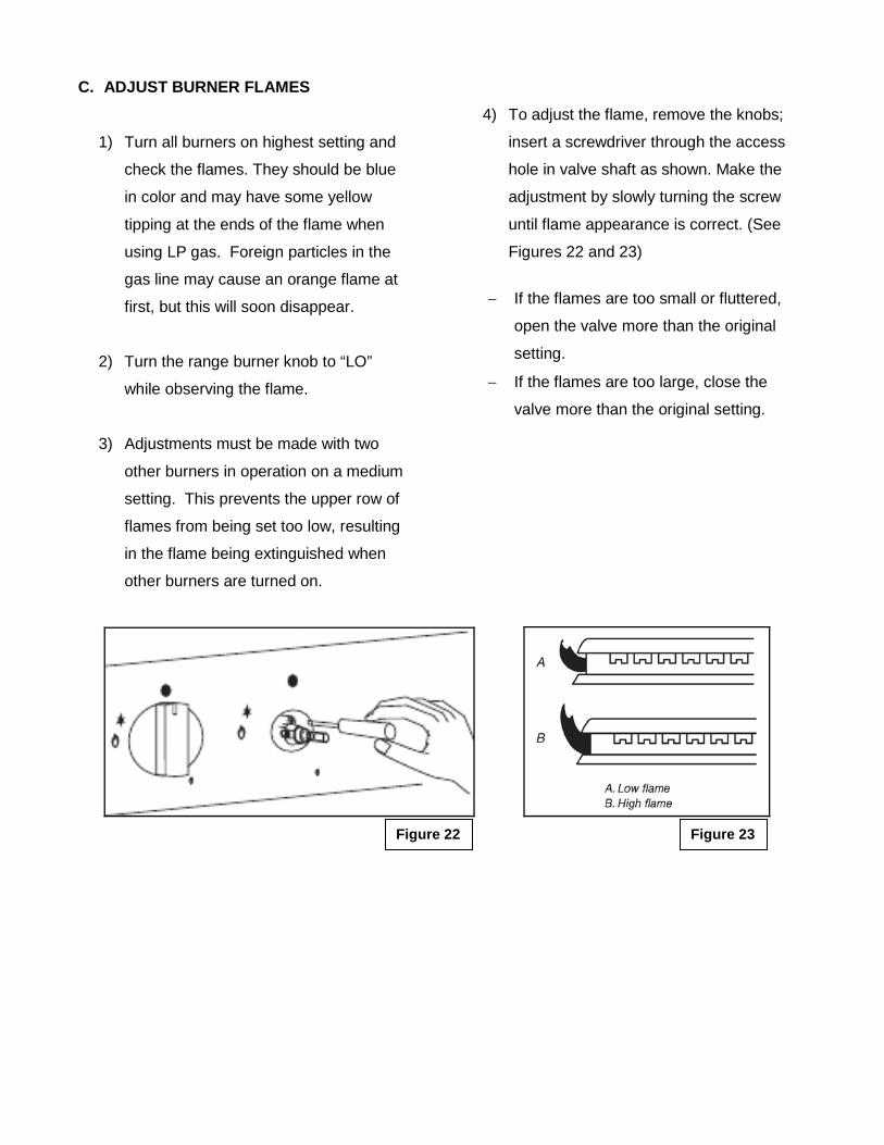
C. ADJUST BURNER FLAMES
1) Turn all burners on highest setting and
check the flames. They should be blue
in color and may have some yellow
tipping at the ends of the flame when
using LP gas. Foreign particles in the
gas line may cause an orange flame at
first, but this will soon disappear.
2) Turn the range burner knob to “LO”
while observing the flame.
3) Adjustments must be made with two
other burners in operation on a medium
setting. This prevents the upper row of
flames from being set too low, resulting
in the flame being extinguished when
other burners are turned on.
4) To adjust the flame, remove the knobs;
insert a screwdriver through the access
hole in valve shaft as shown. Make the
adjustment by slowly turning the screw
until flame appearance is correct. (See
Figures 22 and 23)
− If the flames are too small or fluttered,
open the valve more than the original
setting.
− If the flames are too large, close the
valve more than the original setting.
Figure 22
Figure 23
TESTING FLAME STABILITY Test 1——Turn the knob from “HI” to “LO” quickly. If the upper row of flames goes out at this setting,
increase the flame size and test again. Test 2——With the burner on “LO”, open and close the cabinet door under the range. If the flame is
extinguished by the air currents created by the door movement, increase the flame height and test
again.
D. FLAME RE-CHECK After the adjustment is made, turn all burners off. Ignite each burner individually. Observe the flame
at the “HI” position. Rotate the knob to the lowest setting and be sure that the flame size decreases
as the knob is rotated counter-clockwise.
Adjust the height of top burner flames. The range “low” burner flame should be a steady blue flame
approximately ¼" (0.64 cm) high.
Once the conversion has been completed and has passed testing, fill out the conversion sticker and include your name, organization and the date conversion is made. Apply the sticker near the appliance gas inlet opening to alert others in the future that this appliance has been converted. If converting back to Natural Gas, please remove the sticker so others know that the appliance is set to use its original gas.
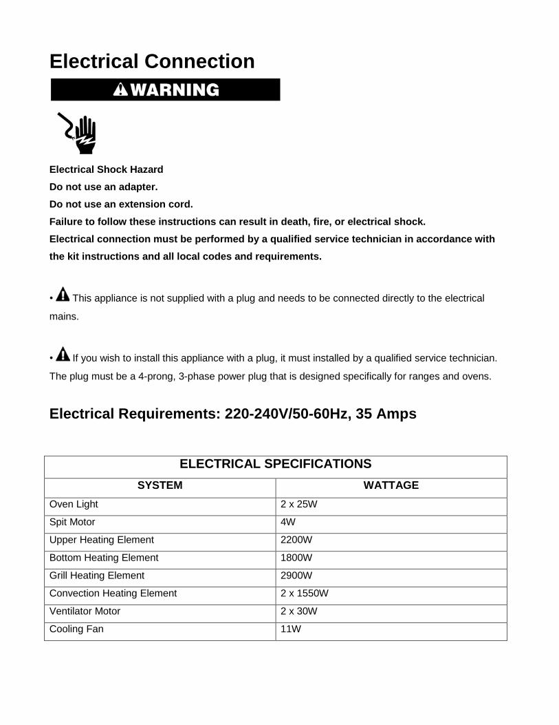
Electrical Connection
Electrical Shock Hazard Do not use an adapter. Do not use an extension cord. Failure to follow these instructions can result in death, fire, or electrical shock. Electrical connection must be performed by a qualified service technician in accordance with the kit instructions and all local codes and requirements.
• This appliance is not supplied with a plug and needs to be connected directly to the electrical
mains.
• If you wish to install this appliance with a plug, it must installed by a qualified service technician.
The plug must be a 4-prong, 3-phase power plug that is designed specifically for ranges and ovens.
Electrical Requirements: 220-240V/50-60Hz, 35 Amps
ELECTRICAL SPECIFICATIONS SYSTEM WATTAGE
Oven Light 2 x 25W
Spit Motor 4W
Upper Heating Element 2200W
Bottom Heating Element 1800W
Grill Heating Element 2900W
Convection Heating Element 2 x 1550W
Ventilator Motor 2 x 30W
Cooling Fan 11W
BEFORE MAKING THE ELECTRICAL CONNECTION, MAKE SURE THAT:
• The safety circuit-breaker and the electrical system are able to with stand the load of the
appliance. See rating label on back of range.
• Rating plate is located on back of range should you need to verify any of the electrical
requirements.
• The power supply system has a ground connection in good working order in accordance with the
regulations in force.
• The electrical socket is easily accessible with the appliance installed. In all cases, the power
supply lead must be positioned so that it does not reach a temperature of 50oC above the room
temperature at any point.
• The manufacturer is not liable for any direct or indirect damage caused by faulty installation or
connection. It is therefore necessary that all installation and connection operations are carried out by
qualified personnel complying with the local and general regulations in force.
CONNECTION OF THE RANGE WIRES TO THE MAINS
1) This appliance is equipped with the following wires:
• Two black wires (L1 and L2 - Live)
• One yellow /green (Ground)
2) Follow the diagram below to know how to connect the freestanding range wires to the
electrical main wires of the home. (See Figure 24)
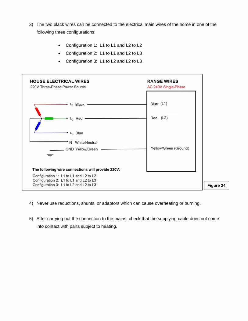
3) The two black wires can be connected to the electrical main wires of the home in one of the
following three configurations:
• Configuration 1: L1 to L1 and L2 to L2
• Configuration 2: L1 to L1 and L2 to L3
• Configuration 3: L1 to L2 and L2 to L3
4) Never use reductions, shunts, or adaptors which can cause overheating or burning.
5) After carrying out the connection to the mains, check that the supplying cable does not come
into contact with parts subject to heating.
Figure 24
Surface Cooking Flame Size • For most cooking, start on the highest control setting and then turn to a lower one to complete the
process. The size and type of utensil used and the amount of food being cooked will influence the
setting needed for cooking.
• For deep fat frying, use a thermometer and adjust the surface control knob accordingly. If the fat is
too cool, the food will absorb the fat and be greasy. If the fat is too hot, the food will brown so quickly
that the center will be undercooked. Do not attempt to deep fry too much food at once as the food will
neither brown nor cook properly.
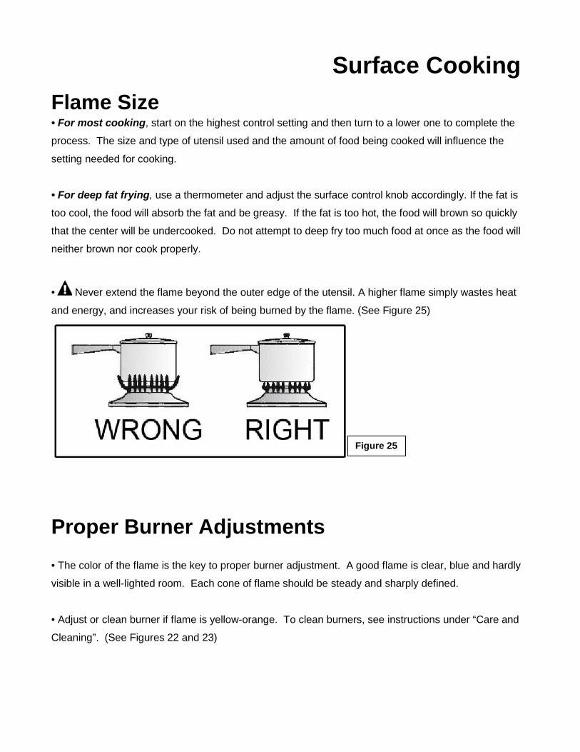
• Never extend the flame beyond the outer edge of the utensil. A higher flame simply wastes heat
and energy, and increases your risk of being burned by the flame. (See Figure 25)
Proper Burner Adjustments
• The color of the flame is the key to proper burner adjustment. A good flame is clear, blue and hardly
visible in a well-lighted room. Each cone of flame should be steady and sharply defined.
• Adjust or clean burner if flame is yellow-orange. To clean burners, see instructions under “Care and
Cleaning”. (See Figures 22 and 23)
Figure 25
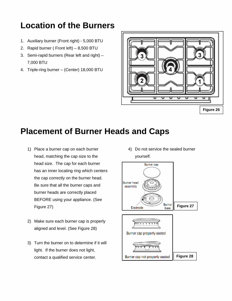
Location of the Burners
1. Auxiliary burner (Front right) - 5,000 BTU
2. Rapid burner ( Front left) – 8,500 BTU
3. Semi-rapid burners (Rear left and right) –
7,000 BTU
4. Triple-ring burner – (Center) 18,000 BTU
Placement of Burner Heads and Caps
1) Place a burner cap on each burner
head, matching the cap size to the
head size. The cap for each burner
has an inner locating ring which centers
the cap correctly on the burner head.
Be sure that all the burner caps and
burner heads are correctly placed
BEFORE using your appliance. (See
Figure 27)
2) Make sure each burner cap is properly
aligned and level. (See Figure 28)
3) Turn the burner on to determine if it will
light. If the burner does not light,
contact a qualified service center.
4) Do not service the sealed burner
yourself.
Figure 28
Figure 27
Figure 26
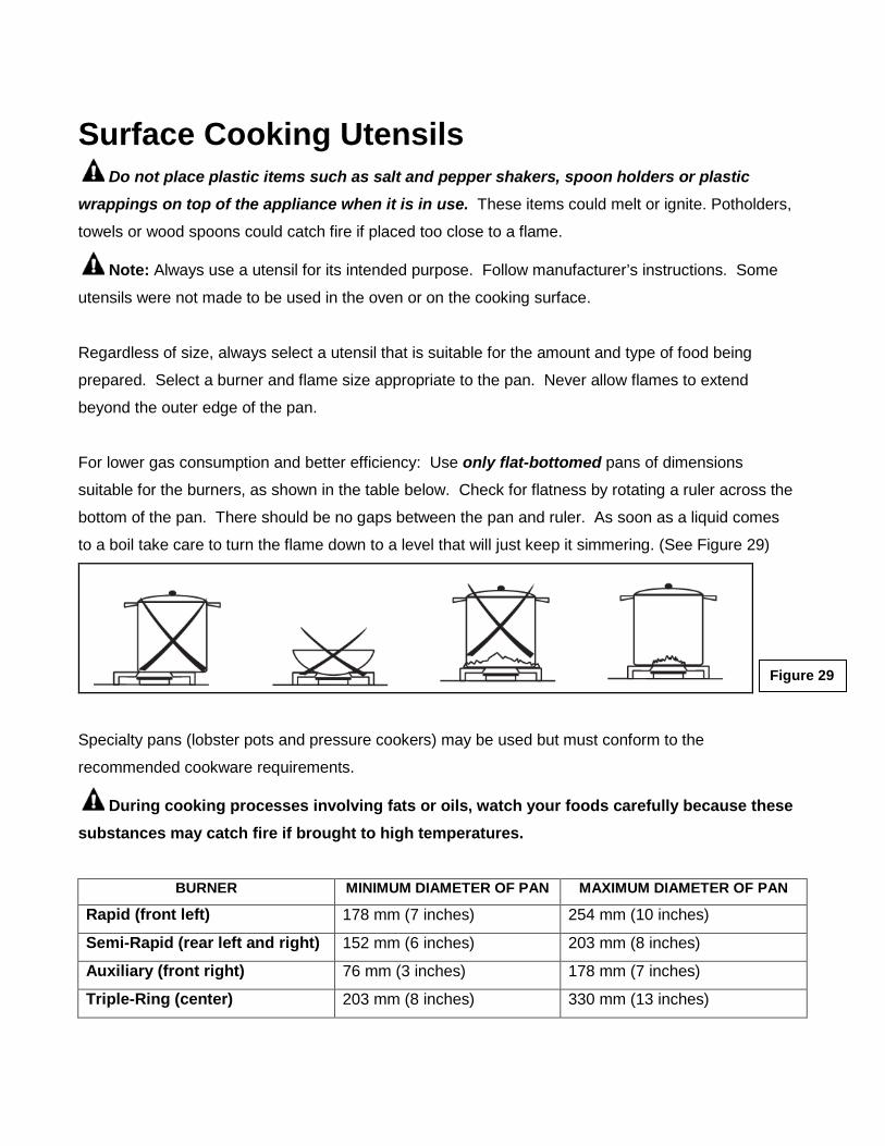
Surface Cooking Utensils Do not place plastic items such as salt and pepper shakers, spoon holders or plastic
wrappings on top of the appliance when it is in use. These items could melt or ignite. Potholders,
towels or wood spoons could catch fire if placed too close to a flame.
Note: Always use a utensil for its intended purpose. Follow manufacturer’s instructions. Some
utensils were not made to be used in the oven or on the cooking surface.
Regardless of size, always select a utensil that is suitable for the amount and type of food being
prepared. Select a burner and flame size appropriate to the pan. Never allow flames to extend
beyond the outer edge of the pan.
For lower gas consumption and better efficiency: Use only flat-bottomed pans of dimensions
suitable for the burners, as shown in the table below. Check for flatness by rotating a ruler across the
bottom of the pan. There should be no gaps between the pan and ruler. As soon as a liquid comes
to a boil take care to turn the flame down to a level that will just keep it simmering. (See Figure 29)
Specialty pans (lobster pots and pressure cookers) may be used but must conform to the
recommended cookware requirements.
During cooking processes involving fats or oils, watch your foods carefully because these substances may catch fire if brought to high temperatures.
BURNER MINIMUM DIAMETER OF PAN MAXIMUM DIAMETER OF PAN
Rapid (front left) 178 mm (7 inches) 254 mm (10 inches)
Semi-Rapid (rear left and right) 152 mm (6 inches) 203 mm (8 inches)
Auxiliary (front right) 76 mm (3 inches) 178 mm (7 inches)
Triple-Ring (center) 203 mm (8 inches) 330 mm (13 inches)
Figure 29
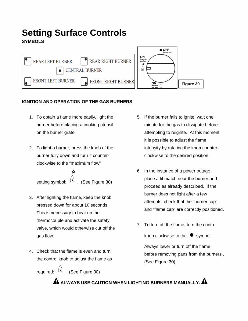
Setting Surface Controls SYMBOLS
IGNITION AND OPERATION OF THE GAS BURNERS
1. To obtain a flame more easily, light the
burner before placing a cooking utensil
on the burner grate.
2. To light a burner, press the knob of the
burner fully down and turn it counter-
clockwise to the “maximum flow”
setting symbol: . (See Figure 30)
3. After lighting the flame, keep the knob
pressed down for about 10 seconds.
This is necessary to heat up the
thermocouple and activate the safety
valve, which would otherwise cut off the
gas flow.
4. Check that the flame is even and turn
the control knob to adjust the flame as
required: . (See Figure 30)
5. If the burner fails to ignite, wait one
minute for the gas to dissipate before
attempting to reignite. At this moment
it is possible to adjust the flame
intensity by rotating the knob counter-
clockwise to the desired position.
6. In the instance of a power outage,
place a lit match near the burner and
proceed as already described. If the
burner does not light after a few
attempts, check that the “burner cap”
and “flame cap” are correctly positioned.
7. To turn off the flame, turn the control
knob clockwise to the: ● symbol.
Always lower or turn off the flame
before removing pans from the burners,.
(See Figure 30)
ALWAYS USE CAUTION WHEN LIGHTING BURNERS MANUALLY.
Figure 30
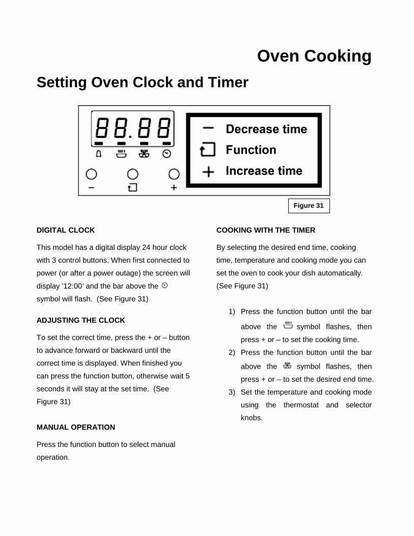
Oven Cooking Setting Oven Clock and Timer
DIGITAL CLOCK This model has a digital display 24 hour clock
with 3 control buttons. When first connected to
power (or after a power outage) the screen will
display ’12:00’ and the bar above the
symbol will flash. (See Figure 31)
ADJUSTING THE CLOCK To set the correct time, press the + or – button
to advance forward or backward until the
correct time is displayed. When finished you
can press the function button, otherwise wait 5
seconds it will stay at the set time. (See
Figure 31)
MANUAL OPERATION Press the function button to select manual
operation.
COOKING WITH THE TIMER By selecting the desired end time, cooking
time, temperature and cooking mode you can
set the oven to cook your dish automatically.
(See Figure 31)
1) Press the function button until the bar
above the symbol flashes, then
press + or – to set the cooking time.
2) Press the function button until the bar
above the symbol flashes, then
press + or – to set the desired end time.
3) Set the temperature and cooking mode
using the thermostat and selector
knobs.
Figure 31
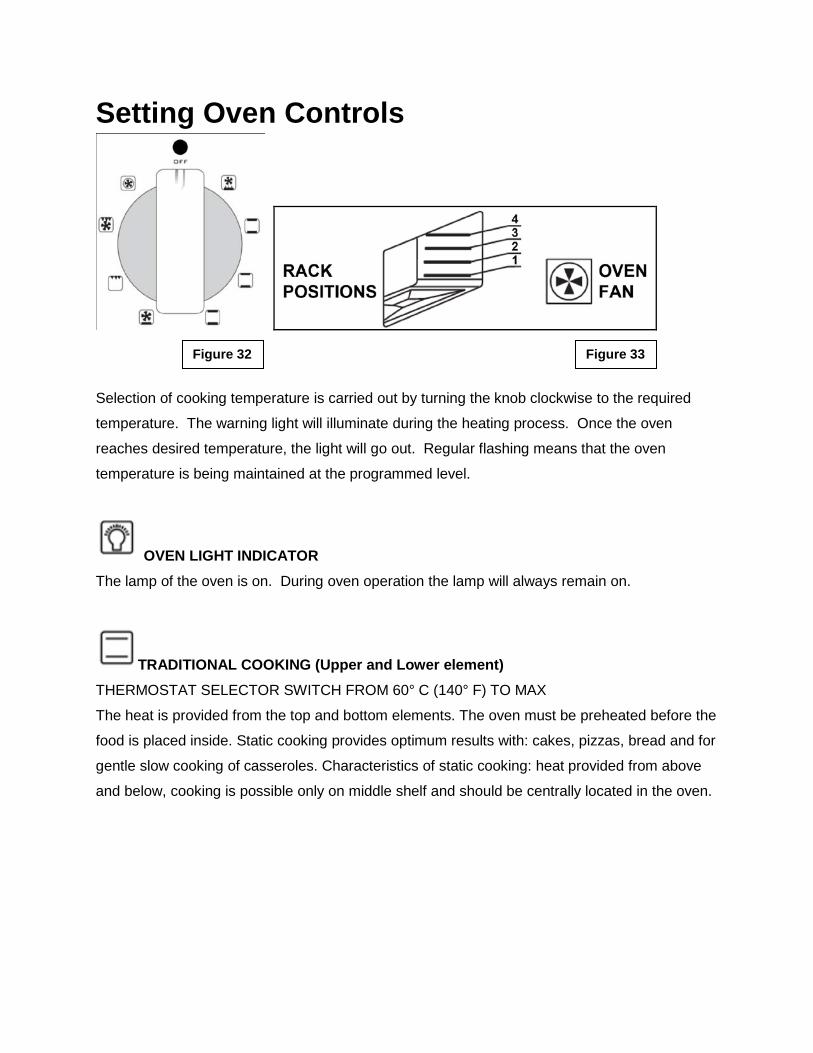
Setting Oven Controls
Selection of cooking temperature is carried out by turning the knob clockwise to the required
temperature. The warning light will illuminate during the heating process. Once the oven
reaches desired temperature, the light will go out. Regular flashing means that the oven
temperature is being maintained at the programmed level.
OVEN LIGHT INDICATOR The lamp of the oven is on. During oven operation the lamp will always remain on.
TRADITIONAL COOKING (Upper and Lower element) THERMOSTAT SELECTOR SWITCH FROM 60° C (140° F) TO MAX
The heat is provided from the top and bottom elements. The oven must be preheated before the
food is placed inside. Static cooking provides optimum results with: cakes, pizzas, bread and for
gentle slow cooking of casseroles. Characteristics of static cooking: heat provided from above
and below, cooking is possible only on middle shelf and should be centrally located in the oven.
Figure 32 Figure 33
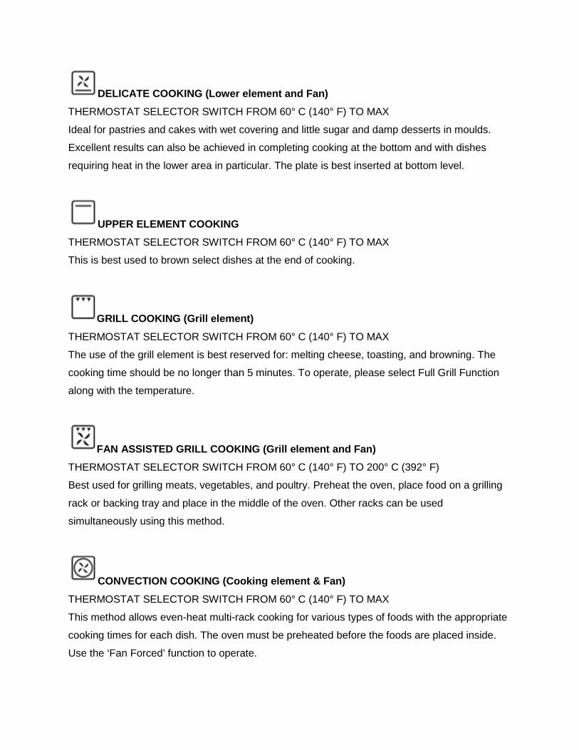
DELICATE COOKING (Lower element and Fan) THERMOSTAT SELECTOR SWITCH FROM 60° C (140° F) TO MAX
Ideal for pastries and cakes with wet covering and little sugar and damp desserts in moulds.
Excellent results can also be achieved in completing cooking at the bottom and with dishes
requiring heat in the lower area in particular. The plate is best inserted at bottom level.
UPPER ELEMENT COOKING THERMOSTAT SELECTOR SWITCH FROM 60° C (140° F) TO MAX
This is best used to brown select dishes at the end of cooking.
GRILL COOKING (Grill element) THERMOSTAT SELECTOR SWITCH FROM 60° C (140° F) TO MAX
The use of the grill element is best reserved for: melting cheese, toasting, and browning. The
cooking time should be no longer than 5 minutes. To operate, please select Full Grill Function
along with the temperature.
FAN ASSISTED GRILL COOKING (Grill element and Fan) THERMOSTAT SELECTOR SWITCH FROM 60° C (140° F) TO 200° C (392° F) Best used for grilling meats, vegetables, and poultry. Preheat the oven, place food on a grilling
rack or backing tray and place in the middle of the oven. Other racks can be used
simultaneously using this method.
CONVECTION COOKING (Cooking element & Fan) THERMOSTAT SELECTOR SWITCH FROM 60° C (140° F) TO MAX
This method allows even-heat multi-rack cooking for various types of foods with the appropriate
cooking times for each dish. The oven must be preheated before the foods are placed inside.
Use the ‘Fan Forced’ function to operate.
DEFROST (Bottom fan) All types of food can be defrosted by circulating air at room temperature: cakes, cream, fruit, etc.
For foods such as: meat, fish, and bread you will want to set the fan temperature to 175-200° C
(347-392° F).
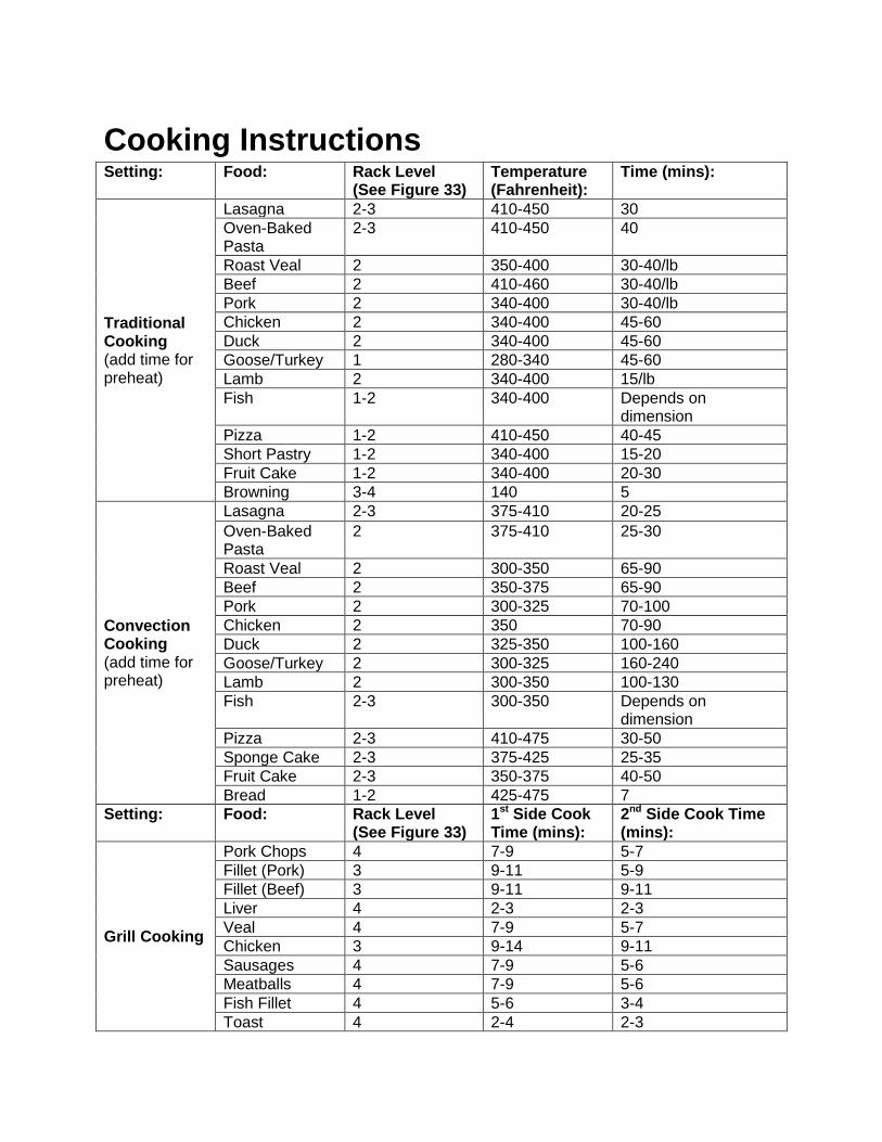
Cooking Instructions Setting: Food: Rack Level
(See Figure 33) Temperature (Fahrenheit):
Time (mins):
Traditional Cooking (add time for preheat)
Lasagna 2-3 410-450 30 Oven-Baked Pasta
2-3 410-450 40
Roast Veal 2 350-400 30-40/lb Beef 2 410-460 30-40/lb Pork 2 340-400 30-40/lb Chicken 2 340-400 45-60 Duck 2 340-400 45-60 Goose/Turkey 1 280-340 45-60 Lamb 2 340-400 15/lb Fish 1-2 340-400 Depends on
dimension Pizza 1-2 410-450 40-45 Short Pastry 1-2 340-400 15-20 Fruit Cake 1-2 340-400 20-30 Browning 3-4 140 5
Convection Cooking (add time for preheat)
Lasagna 2-3 375-410 20-25 Oven-Baked Pasta
2 375-410 25-30
Roast Veal 2 300-350 65-90 Beef 2 350-375 65-90 Pork 2 300-325 70-100 Chicken 2 350 70-90 Duck 2 325-350 100-160 Goose/Turkey 2 300-325 160-240 Lamb 2 300-350 100-130 Fish 2-3 300-350 Depends on
dimension Pizza 2-3 410-475 30-50 Sponge Cake 2-3 375-425 25-35 Fruit Cake 2-3 350-375 40-50 Bread 1-2 425-475 7
Setting: Food: Rack Level (See Figure 33)
1st Side Cook Time (mins):
2nd Side Cook Time (mins):
Grill Cooking
Pork Chops 4 7-9 5-7 Fillet (Pork) 3 9-11 5-9 Fillet (Beef) 3 9-11 9-11 Liver 4 2-3 2-3 Veal 4 7-9 5-7 Chicken 3 9-14 9-11 Sausages 4 7-9 5-6 Meatballs 4 7-9 5-6 Fish Fillet 4 5-6 3-4 Toast 4 2-4 2-3
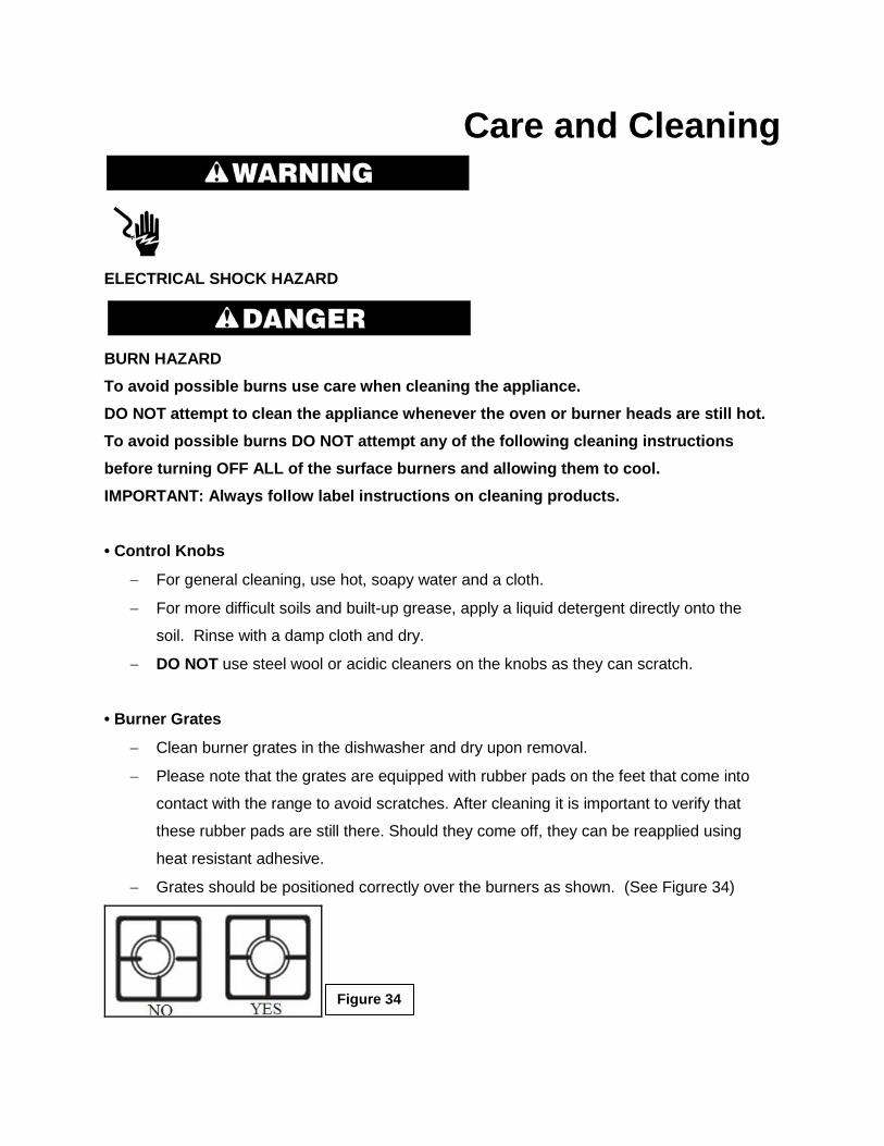
Care and Cleaning
ELECTRICAL SHOCK HAZARD
BURN HAZARD To avoid possible burns use care when cleaning the appliance. DO NOT attempt to clean the appliance whenever the oven or burner heads are still hot. To avoid possible burns DO NOT attempt any of the following cleaning instructions before turning OFF ALL of the surface burners and allowing them to cool. IMPORTANT: Always follow label instructions on cleaning products.
• Control Knobs
− For general cleaning, use hot, soapy water and a cloth.
− For more difficult soils and built-up grease, apply a liquid detergent directly onto the
soil. Rinse with a damp cloth and dry.
− DO NOT use steel wool or acidic cleaners on the knobs as they can scratch.
• Burner Grates
− Clean burner grates in the dishwasher and dry upon removal.
− Please note that the grates are equipped with rubber pads on the feet that come into
contact with the range to avoid scratches. After cleaning it is important to verify that
these rubber pads are still there. Should they come off, they can be reapplied using
heat resistant adhesive.
− Grates should be positioned correctly over the burners as shown. (See Figure 34)
Figure 34
• Burner Caps
− To clean the burner caps, lift the burner cap off the burner head. Clean heavy soils with
an absorbent cloth.
− Rinse with a clean, damp cloth and immediately thoroughly dry including the bottom
and inside of the cap.
− Do not use harsh abrasive cleaners. They can scratch the cap.
− DO NOT PUT BURNER UNITS IN THE DISHWASHER
• Burner Heads
− The holes in the burners of your appliance MUST be kept clean at all times for proper
ignition and a complete, even flame. Remove any food from between the burner slots
using a small nonabrasive brush like a toothbrush and afterwards wipe using a damp
cloth.
− To remove deposits from the burner cavities, remove the cap and separate the two parts.
Clean the burner holes routinely with a small gauge wire or needle and especially after
bad spillovers which could clog these holes.
− After cleaning, put the two parts back together and return them correctly to their position,
making sure they are seated and level.
− DO NOT PUT BURNER UNITS IN THE DISHWASHER
• Stainless Steel
− Clean stainless steel with hot, soapy water and a dishcloth. Rinse with clean water and a
cloth.
− Do not use cleaners with high concentrations of chlorides or chlorines. Do not use harsh
scrubbing cleaners. Only use kitchen cleaners that are especially made for cleaning
stainless steel.
• Inside Oven
− This appliance does NOT have a self-cleaning feature.
− DO NOT attempt to clean the appliance whenever the oven is still hot.
− Use an appropriate cleaning product designed specifically to clean the inside of ovens.
− IMPORTANT: Always follow label instructions on cleaning products.
• Cleaning Interior Lower Grill Element
− To remove the element, support one side with your hand while removing the retainer
with the other.
− When cleaning, make sure not to apply excessive force on the element as it is fragile.
− Reposition the element and secure the retainer back in place.
− DO NOT use the oven with the grill element hanging down – it must be repositioned after
cleaning.
• Storage Drawer
− Make sure drawer is cool and empty before cleaning.
− Use a mild detergent.
• Oven Door Exterior
− Use a glass cleaner and a soft cloth or sponge.
− Apply glass cleaner to soft cloth or sponge, not directly on panel.
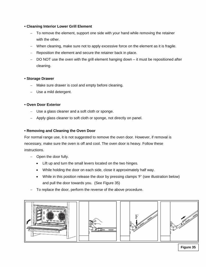
• Removing and Cleaning the Oven Door For normal range use, it is not suggested to remove the oven door. However, if removal is
necessary, make sure the oven is off and cool. The oven door is heavy. Follow these
instructions.
− Open the door fully.
• Lift up and turn the small levers located on the two hinges.
• While holding the door on each side, close it approximately half way.
• While in this position release the door by pressing clamps ‘F’ (see illustration below)
and pull the door towards you. (See Figure 35)
− To replace the door, perform the reverse of the above procedure.
Figure 35
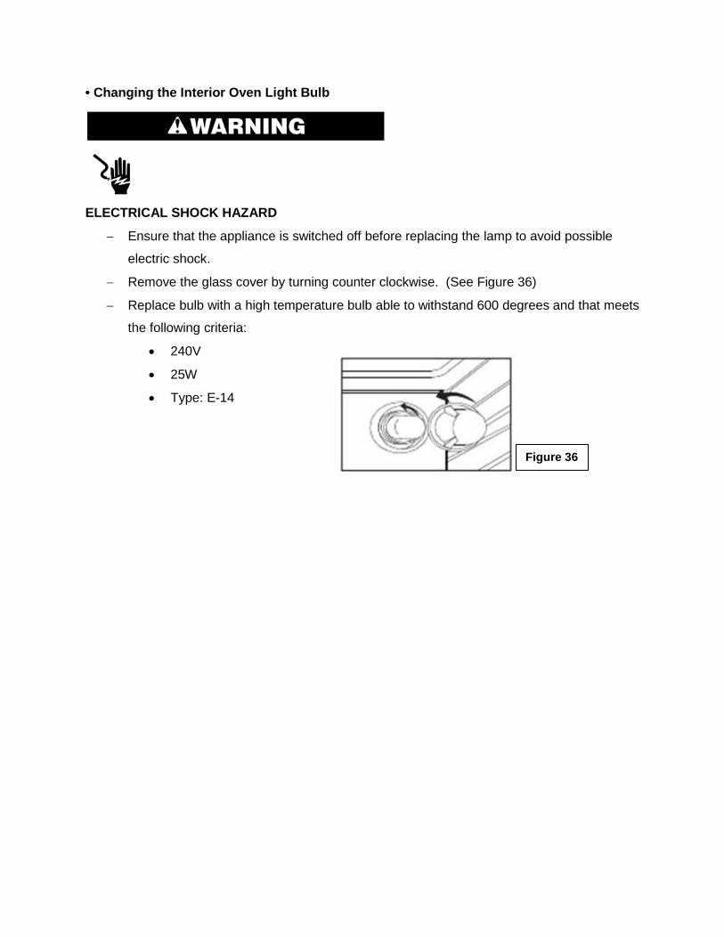
• Changing the Interior Oven Light Bulb
ELECTRICAL SHOCK HAZARD
− Ensure that the appliance is switched off before replacing the lamp to avoid possible
electric shock.
− Remove the glass cover by turning counter clockwise. (See Figure 36)
− Replace bulb with a high temperature bulb able to withstand 600 degrees and that meets
the following criteria:
• 240V
• 25W
• Type: E-14
Figure 36
Solutions to Common Problems IMPORTANT Before calling for service, review this list. It may save you both time and expense. This list includes common experiences that are not the result of defective workmanship or material in your appliance.
Electrical Shock Hazard Plug into a grounded 3 prong outlet. Do not remove ground prong. Do not use an adapter. Do not use an extension cord. Failure to follow these instructions can result in death, fire, or electrical shock. NOTHING WILL OPERATE ■ Is the electrical supply disconnected? Verify that electrical wires are connected to the mains properly. See “Electrical Connection”
section. If the problem continues, contact a qualified technician.
■ Household fuse blown or circuit breaker tripped? Replace the fuse or reset the circuit breaker. If the problem continues, contact a qualified
technician.
■ Is the main or regulator gas shutoff valve in the off position? See “Gas Connection” section.
■ Is the range properly connected to the gas supply? Contact a qualified technician. See “Gas Connection” section.
SURFACE BURNERS WILL NOT OPERATE ■ Is this the first time the surface burners have been used? Turn on any one of the surface burner knobs to release air from the gas lines.
■ Is the control knob set correctly? Push in knob before turning to a setting.
■ Are the burner ports clogged? See “Care and Cleaning” section.
SURFACE BURNERS ARE UNEVEN, YELLOW AND/OR NOISY ■ Are the burner ports clogged? See “Care and Cleaning” section.
■ Are the burner caps positioned properly? See “Placement of Burner Heads and Caps” section.
■ Is propane gas being used? The range may have been converted improperly. Contact a qualified service technician. See
“Liquid Petroleum (Propane) Gas Conversion” section.
SURFACE BURNER MAKES POPPING NOISES ■ Is the burner wet? Let it dry.
EXCESS HEAT AROUND COOKWARE ON COOKING SURFACE ■ Is the cookware the proper size? Use cookware about the same size as the surface cooking area, element or surface burner.
Cookware should not extend more than ½" (1.3 cm) outside the cooking area.
COOKTOP COOKING RESULTS NOT WHAT EXPECTED ■ Is the proper cookware being used? See “Surface Cooking Utensils” section.
■ Is the control knob set to the proper heat level? See “Setting Surface Controls” section.
■ Is the range level? Level the range. See the “Unpack Range / Install Leveling Feet and Back Panel” section.
OVEN WILL NOT OPERATE ■ Are the oven controls set correctly? See “Setting Oven Controls” section.
COOLING FAN RUNS DURING BAKING AND BROILING ■ It is normal for the fan to automatically run while the oven is in use and for some time after to
cool.
OVEN TEMPERATURE TOO HIGH OR TOO LOW
■ Was the oven preheated? See “Cooking Instructions” section.
■ Are the racks positioned properly? See “Cooking Instructions” section.
■ Is there proper air circulation around bakeware? See “Cooking Instructions” section.
■ Is the batter evenly distributed in the pan? Check that batter is level in the pan.
■ Is the proper length of time being used? Adjust cooking time.
■ Has the oven door been opened while cooking? Oven peeking releases oven heat and can result in longer cooking times.
■ Are baked items too brown on the bottom? Move rack to higher position in the oven.
■ Are pie crust edges browning early? Use aluminum foil to cover the edge of the crust and/or reduce baking temperature.
NO SPARK WHEN LIGHTING BURNER ■ Electrical supply - The electrical wires or the plug are not connected well. Connect with electrical power again. If the problem continues, contact a qualified technician.
■ Burner - The burner is not installed correctly. Install the burner again. See “Placement of Burners and Caps” section.
■ Spark pin - Ignition electrode and the hole are not placed well. Install the burner again. See “Placement of Burners and Caps” section.
THE FIRE GOES OUT ONCE RELEASING THE KNOB ■ Safety valve - Knob not pressed down long enough.
Press and turn the knob again and keep 3 to 5 seconds after the burner has been lit. BURNER WON’T IGNITE OR BURNS UNEVENLY
■ Gas valve - The valve is not open. Make sure the valve is completely open. ■ Gas pipe - There may be air in the gas pipe. Ignite repeatedly until flame catches. ■ Burner cap
− The burner cap is not placed correctly. o Replace the burner cap.
− Some holes in the lid are stocked. o Clean the holes of the lid.
■ Spark pin - The spark pin is wet or contaminated by the food. Clean and dry the spark pin.. ■ Gas connecting pipes - The gas connecting pipes are stocked or squashed. Contact a qualified technician. Adjust or change the connecting pipes. THE FLAME GOES OUT DURING OPERATION ■ Thermocouple
− The safety device is contaminated. o Clean the thermocouple.
− The flame is so little that it can’t touch the thermocouple o Adjust the flame a little bigger. See the “Proper Burner Adjustments” section.
STRANGE SMELL
■ Gas leaking - Contact a qualified technician
− The gas supply pipe is old and broken. o The main burner is not lit.
− Change the gas supply pipe. o Ignite again after there is no strange smell.