User Manual Getting Started with SD-View 2000 - VF...
56
Supervision System User Manual Getting Started with SD-View 2000 Release 2.0 July 2006
Transcript of User Manual Getting Started with SD-View 2000 - VF...

Supervision SystemUser ManualGetting Started with SD-View 2000
Release 2.0July 2006


ABB SACE 1SDH00513R0002 - L2934
SD-View 2000
Index
1. SD-View 2000 Setup........................................ 1/3
2. How to get the licence.................................... 2/1
3. SD-Testbus2 Setup.......................................... 3/1
4. Starting SD-Testbus2....................................... 4/1
5. Starting SD-View 2000 Configurator.............. 5/1
5.1 Serial Port Configuration.................... 5.1/6
5.2 Unit Configuration............................... 5.2/12
6. SD-View 2000 Configurator Plug-in
for SD-TestBus2 ............................................. 6/1
6.1 User’s Manual...................................... 6.1/3
7. Starting SD-View 2000.................................... 7/1

ABB SACE 1SDH00513R0002 - L2934
SD-View 2000

ABB SACE 1/31SDH00513R0002 - L2934
1. Setup SD-View 2000
1. SD-View 2000 SetupThe aim of this Help is to lead the user to a proper installation of SD-View 2000, to the configuration of the serial ports and of the protection devices. For a correct installation of the product, the user has to follow the steps shown in this paragraph.
Warning: It is mandatory to remove a previous version of SD-View 2000 before proceeding with a new installation. The removing procedure will delete all your current data so it is useful to backup them before continuing.
How to install SD-View 2000
1st StepInsert the SD-View 2000 CD and wait for the Installation Launcher of ABB to auto-start. If the auto-run function is not active, proceed as follows:
• Click “My Computer” ;
• Click the CD-ROM unit where the SD-View 2000 CD has been inser-
ted ;
• Click to run the ABB CD Installation Launcher.
Select “SD-View 2000” and click “Next” to proceed.

ABB SACE 1/41SDH00513R0002 - L2934
1. Setup SD-View 2000
This is the first installation screenshot :
2nd StepBefore proceeding with the installation, read the license agreement and click “YES” to accept.

ABB SACE 1/51SDH00513R0002 - L2934
1. Setup SD-View 2000
3rd Step Insert “User Name” and “Company Name” in the default fields and click “Next”.
4th Step Click “Next” to accept the default folder.
Otherwise click “Browse”, if the installation of “SD-View 2000” to a different folder from the default one is desired.

ABB SACE 1/61SDH00513R0002 - L2934
1. Setup SD-View 2000
The language among the two available, Italian and English, is auto-matically set by the installation program according to the settings of the PC.
5th StepThe moving bar indicates the status of the installation procedure. Wait for the installation to end and click “Finish” to complete the set-up of SD-View 2000. Click “Finish” to restart the system.
Click “OK” to choose a new path and later “Next” to proceed with the installation.

ABB SACE 1SDH00513R0002 - L2934
2/1
2. How to get the license
2. How to get the licenseIn order to proceed with the registration of the product, it is necessary to purchase the licensed version and send the identification code of the USB key to the following e-mail address: [email protected]. ABB SACE will send the “.dat” license file which has to be copied in the in the following folder “\ABB Industrial IT\SD-View 2000”.
1st StepFollow the path Start ->Programs ->ABB->SD-View 2000->SD-View 2000 Application ->System Setup, click the “System Setup”
icon to pop the following screenshot up:

ABB SACE 1SDH00513R0002 - L2934
2. How to get the license
2/2
2nd Step Click “Client and Server” and then activate the license registration screenshot by selecting “License Entry”:

ABB SACE 1SDH00513R0002 - L2934
2/3
2. How to get the license
3rd Step Connect the USB-key license to the PC, click the “Add From File” but-ton to load the license file. It is possible to choose the correct path of the license file through a pop-up menu that will be displayed.
Select the license file and click “Open”. Automatically all the form fields will be filled in according to the file loaded, as shown in the following screenshot.
4th Step To enable the license it is necessary to validate it, to save the license settings and then to test the settings. All the mentioned operations can be enabled clicking these buttons:
• First the “Validate” button;
• Then the “Save” button;
• At the end the “Test Checkout” button.
5th Step Select “Drivers” from the “Feature” pop-up menu and repeat the 3rd e 4th step.
6th StepClose the “System Setup” application.

ABB SACE 1SDH00513R0002 - L2934
SD-View 2000

ABB SACE 3/11SDH00513R0002 - L2934
3. SD-TestBus2 Setup
3. SD-TestBus2 Setup Before proceeding with the SD-View 2000 configuration, the user has to scan the network status. This operation is necessary to avoid problems during the communication among SD-View 2000 and field devices.
SD-TestBus2 is the product that makes it possible to verify the com-munication and the connections among a Modbus Master and ABB SACE field devices. The necessary steps for a correct setup of this application are listed in the following:
1st StepInsert the SD-View 2000 and wait for the Installation Launcher of ABB to auto-start. If the auto-run function is not active, proceed as follows:
• Click “My Computer” ;
• Click the CD-ROM unit where the SD-View 2000 CD has been inser-
ted ;
• Click to run the ABB CD Installation Launcher.

ABB SACE 3/21SDH00513R0002 - L2934
3. SD-TestBus2 Setup
Select “SD-TestBus2” and click “Next” to proceed. This is the first in-stallation screenshot :
2nd StepBefore proceeding with the installation, read the license agreement and click “YES” to accept.

ABB SACE 3/31SDH00513R0002 - L2934
3. SD-TestBus2 Setup
4th Step Otherwise click “Browse”, if the installation of “SD-TestBus2” to a diffe-rent folder from the default one is desired
3rd Step Click “Next” to accept the default folder.

ABB SACE 3/41SDH00513R0002 - L2934
3. SD-TestBus2 Setup
Click “OK” to choose a new path and later “Next” to proceed with the installation
5th Step Select one of the two available languages and click “Next” to proceed.

ABB SACE 3/51SDH00513R0002 - L2934
3. SD-TestBus2 Setup
6th Step Click “Next” to confirm the installation.
7th Step The status of the set-up process is indicated by the “Progress Bar”.

ABB SACE 3/61SDH00513R0002 - L2934
3. SD-TestBus2 Setup
8th Step Click “Close” to finish the installation procedure.

ABB SACE 1SDH00513R0002 - L2934
4. Starting SD-TestBus2
4/1
4. Starting SD-TestBus2
IMPORTANT : It is useful to read this section after having installed SD-TestBus2
In the following steps it will be described how to start the scanning of the network and how to detect the devices or any communication problem. The properties of the product will not be fully described here but in a specific manual.
1st StepTo start “SD-TestBus2” click its icon on the desktop.

ABB SACE 1SDH00513R0002 - L2934
4. Starting SD-TestBus2
4/2
2nd StepClick “Bus” in the menu and choose “Scan”.
A pop-up menu will be displayed to allow the user to select the settings for the scanning.
This is the information you can set:
• Serial Port;
• Communication Speed - 9600/19200 for ABB SACE devices;
• Even Parity for ABB SACE devices;
• Sniff Timeout (ms) with the possibility to find the Master;
• Timeout (ms);
• Modbus address/addresses selection field;
• 1..31 and 1..247 Modbus address interval buttons;
• “Restore” button to reset the settings in the address field;
• “OK” button to start scanning;

ABB SACE 1SDH00513R0002 - L2934
4. Starting SD-TestBus2
4/3

ABB SACE 1SDH00513R0002 - L2934
4. Starting SD-TestBus2
4/4
3rd StepAfter selecting the scanning settings, click “OK” to start the network scanning. As it starts, the status of the scanning will be indicated by a percent increase bar, as shown here.
It is possible to stop the scanning process clicking the “STOP_SCAN!” button.
If the scanning is over and no device has been found, a pop-up menu will indicate if there are problems with the RS-232 cable.

ABB SACE 1SDH00513R0002 - L2934
4. Starting SD-TestBus2
4/5
The reported information for each found device is :
• PR212 @ 3 indicating the PR212 type device and its 3 Modbus ad-dress;
• Serial port;
• Modbus address;
• Communication speed;
• Parity;
• Stop bits;
• Addressing type;
4th StepIf during the scanning process some devices are connected, they are found with their main features.

ABB SACE 1SDH00513R0002 - L2934
4. Starting SD-TestBus2
4/6
5th StepAt the end of the scanning process the complete list of the found devi-ces will be displayed.
With the side navigation tree it’s possible to work dynamically on the device options and have more information.

ABB SACE 1SDH00513R0002 - L2934
5. Starting SD-View 2000 Configurator
5/1
5. Starting SD-View 2000 Configurator The aim of this online Help is to give the necessary information for a correct and simple use of SD-View 2000 Configurator. From now on, we will use the term Configurator as a synonym of SD-View 2000 Con-figurator.
The configuration process of the plant, with the help of the Configurator, is the first step for a correct use of SD-View 2000 system. A wrong setting during the configuration process can compromise the commu-nication with the configured units of the plant.
In order to start the Configurator select Start->Programs->ABB -
>SD-View 2000->SD-View 2000 Configurator
What is possible to do with the Configurator :
• Unit configuration ( ex. Emax, Tmax, ... )
• Serial Port configuration ( ex. COM1, COM2, ... )
• Delete every single unit or serial port
• Delete the entire configuration
• Import or export an entire configuration
• Access to the online Help
• Access to Display Builder
The advantages of the ConfiguratorSD-View 2000 Configurator is a powerful tool for simplifying the plant engineering process.
It guarantees:
• Ease of use thanks to an intuitive graphic interface
• Support for system upgrade and maintenance
• Time and cost reduction in plant system installation
• Native support for a wide range of ABB products
• Easily upgradeable to new products
• Strong integration with SD-TestBus2

ABB SACE 1SDH00513R0002 - L2934
5. Starting SD-View 2000 Configurator
5/2
Configurator User InterfaceThe user interface for all the configuration operations is shown in the following screenshot:
The user interface is divided in two frames:
• The left frame is used for navigating through the configured items
• The right frame is used for accessing item details

ABB SACE 1SDH00513R0002 - L2934
5. Starting SD-View 2000 Configurator
5/3
• Build: saves the created configuration, serial ports and units
• Import: imports a configuration from a xml file
• Export: exports the configuration to a xml file
• Exit: exits from the application.
Command Menu
• New Port: creates a new serial port for the communication
• New Unit: creates a new unit
• Delete: deletes the selected item (unit, port or entire configuration)
• Logon/Logoff: used for user identification
View Menu
• Toolbar: enables/disables the toolbar;
• Status Bar: enables/disables the status bar;
• Property: allows to view the details about serial port or unit
Help Menu
• SD-View 2000 Configurator Help: access to this help
• About: information about SD-View 2000 Configurator version
The menu has the following entries:
Project Menu

ABB SACE 1SDH00513R0002 - L2934
5. Starting SD-View 2000 Configurator
5/4
The toolbar has the following entries:
• New Port: displays the dialog for the creation of a new serial port
New Unit icon
• New Unit: displays the dialog for the creation of a new unit
Build icon
• Build: saves and build the configuration created by the user
Logon/Logoff icon
• Logon/Logoff : allows user identification. You need the highest per-mission level for executing configuration actions
Delete icon
• Delete: deletes the selected item (unit, port or entire configuration)
New Port icon

ABB SACE 1SDH00513R0002 - L2934
5. Starting SD-View 2000 Configurator
5/5
Serial Port or Unit Property icon
• Property: displays the details of the serial port or unit
View Layout icons
Display Builder icon
• Display Builder: starts the Display Builder application for the crea-tion of the synoptic pages
Help icon
• View Layout: allows to modify the view layout, in the right frame, of the configured items
• Configurator Help: displays this help
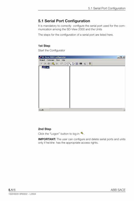
ABB SACE 1SDH00513R0002 - L2934
5.1/6
5.1 Serial Port Configuration
5.1 Serial Port Configuration It is mandatory to correctly configure the serial port used for the com-munication among the SD-View 2000 and the Units
The steps for the configuration of a serial port are listed here.
1st StepStart the Configurator
2nd Step
Click the “Logon” button to log in .
IMPORTANT: The user can configure and delete serial ports and units only if he/she has the appropriate access rights.

ABB SACE 1SDH00513R0002 - L2934
5.1/7
5.1 Serial Port Configuration
3rd Step
Click on the “New Port” button, a pop-up menu will be displayed. It’s possible to select from one of the available ports with the pull down menu (ex. COM1, COM2, ..., COM8 ).
4th StepOnce the serial port is selected, for example COM1, it’s necessary to proceed setting its communication parameters.
• Click “Enabled” Checkbox to enable the serial port;
• Click “Advanced” to set the following options :
- Baud rate
- Data bits - Parity - Stop bits

ABB SACE 1SDH00513R0002 - L2934
5.1/8
5.1 Serial Port Configuration
• Click “OK” to finish.

ABB SACE 1SDH00513R0002 - L2934
5.1/9
5.1 Serial Port Configuration
The serial port has been configured, the relevant icon will be added in the Configurator window.
5th StepClick the “Build” button, to compile and save the configured serial port. When the operations are over, a Pop-up menu will be displayed infor-ming the configuration has been properly saved.

ABB SACE 1SDH00513R0002 - L2934
5.1/10
5.1 Serial Port Configuration
Deleting a Serial PortThe steps to delete a previously configured serial port are listed here.
Click the “Logon” button to log in .
IMPORTANT : The user can configure and delete serial ports and units only if he/she has the appropriate access rights.
1st Step
Choose the serial port to eliminate from the configuration and click on
the “Delete” button.
2nd StepA pop-up menu will be displayed to confirm that the configured serial port will be deleted.

ABB SACE 1SDH00513R0002 - L2934
5.1/11
5.1 Serial Port Configuration
If the deleting operations are successful, this is the pop-up that will be displayed:
WARNING: If you delete a serial port all the configured Units connected to such port are eliminated from the configuration
3rd Step
Close the Configurator.

ABB SACE 1SDH00513R0002 - L2934
5.2/12
5.2 Unit Configuration
5.2 Unit ConfigurationIMPORTANT : Before reading this help page, for the configuration of a single unit, it is necessary to read the page about the configuration of the serial port.
After the correct configuration at least of a serial port, it’s possible to configure one or more units that will communicate with SD-View 2000.
The necessary steps for a correct configuration of a single unit are listed here. They are the same in the case of the configuration of more units.
1st Step
Click on the “Logon” button to log in .
IMPORTANT : The user can configure and delete serial ports and units only if he/she has the appropriate access rights.
2nd Step
Click on the icon of COM1 port, the “New Unit” button will be displayed.

ABB SACE 1SDH00513R0002 - L2934
5.2/13
5.2 Unit Configuration
4th Step
A single Unit is configured using the following menu.
Unit Name• The name of the Unit must comply with these rules :
- Maximum extension of 6 characters
- The accepted characters are numbers, letters, “-” and “_”
- Special characters like “<”, “>” , “/” are not accepted
Extended Unit Name• The extended Unit name must comply with the same rules of the Unit
Name field :
- Maximum extension of 80 characters
- The accepted characters are numbers, letters, “-”, “_”, “(“, “)” and the space
- Special characters like “<”, “>” , “/” are not accepted.
3rd Step
Click on the “New Unit” button , a pop-up menu will be di-splayed.

ABB SACE 1SDH00513R0002 - L2934
5.2/14
5.2 Unit Configuration
Port• It reports the name of the serial port for which the unit is being con-
figured.
Modbus Address• The numerical value of the following field must comply with these
rules:
- Value between 1 and 247
- It’s not allowed to have two units with the same value in the same port.
Unit Type
• It enables to choose the switchboard type (Emax, Isomax, Tmax etc.).
Device Type
• It enables to choose the template of the protection device according to the chosen Unit Type field.
Subunit Name 1 and Subunit Name 2• It enables to set the name of the subunits according to the type
of the chosen AC31.
- Maximum extension of 40 characters
- The accepted characters are numbers, letters, “-”, “_”, “(“, “)” and the space
- Special characters like “<”, “>” , “/” are not accepted.
Switchboard Name• It enables to set the name of the switchboard to which the unit be-
longs or to set the name of an already existing switchboard.
- Maximum extension of 40 characters
- The accepted characters are numbers, letters, “-” and “_”
- Special characters like “<”, “>” , “/” are not accepted.

ABB SACE 1SDH00513R0002 - L2934
5.2/15
5.2 Unit Configuration
After having configured the Unit, the Configurator will appear as fol-lows:
5th Step
Click the “Build” button to build and save the configured Unit. When the operations are over, a pop-up menu will be displayed to con-firm that the configuration has been properly saved.
Deleting a unitThe necessary steps to delete a previously configured Unit are listed here.
1st Step
Click the “Logon” button to log in .
IMPORTANT : The user can configure and delete serial ports and Units only if he/she has the appropriate access rights.

ABB SACE 1SDH00513R0002 - L2934
5.2/16
5.2 Unit Configuration
2nd StepSuppose to start with a Unit already present on the COM1 serial port.
Click on the icon of the Unit. The “Delete” button will be enabled.
3rd Step
Click on the “Delete” button , a pop-up menu will be displayed. Click on ‘Yes’ to delete the Unit.
If the deleting operations is successful, this pop-up will be displayed:
4th StepClose the Configurator

ABB SACE 1SDH00513R0002 - L2934
6. SD-View 2000 Configurator Plug-in for SD-TestBus2
Introduction
6/1
6. SD-View 2000 Configurator Plug-in for SD-TestBus2 IntroductionSD-View 2000 Configurator Plug-in for SD-TestBus2 is an applica-tion that allows to use the information got from a SD-TestBus2 scan process for configuring SD-View 2000. This will reduce the configuration time and make the engineering pro-cess easier, more consistent and less error-prone.
Normally, the configuration engineer is required to use SD-View 2000 Configurator for configuring SD-View 2000. This is the main and most flexible procedure, but it requires to manually introduce configuration data. The plug-in can be seen as a simplified version of SD-View 2000 Con-figurator, where most of the configuration data is taken from SD-Test-Bus2.
Main features • Easy access from SD-TestBus2
• Multi-ports management support
• Incremental configuration building starting from existing SD-View 2000 configuration
• Automatic management of the following port parameters:
- Port name
- Baud rate
- Parity
- Data bits
- Stop bits
and the following unit parameters:
- Device type
- Modbus address

ABB SACE 1SDH00513R0002 - L2934
6. SD-View 2000 Configurator Plug-in forSD-TestBus2
Introduction
6/2
• Suggested default values, eventually editable by the user, for the following port parameters:
- Number of reconnection retries
- Reconnection delay
and the following unit parameters:
- Unit name
- Unit extended name
- Unit type
- Switchboard name
• Support for user identification and privilege checking
SD-View 2000 Configurator Plug-in for SD-TestBus2 can be used even when a previous SD-View 2000 configuration exists. The plug-in is able to determine whether the information found by SD-TesBus2 are in conflict with what previously configured in SD-View 2000. If this is the case, the user will be alerted.
The plug-in is based on SD-View 2000 Configurator and it requires SD-View 2000 to be installed on the same computer where SD-TestBus2 is running.

ABB SACE 1SDH00513R0002 - L2934
6.1/3
6.1 SD-View 2000 Configurator Plug-in for SD-TestBus2
User’s Manual
6.1 SD-View 2000 Configurator Plug-in for SD-TestBus2 - User’s Manual Launching the plug-in SD-View 2000 Configurator Plug-in for SD-TestBus2 is executed from SD-TestBus2, go to “Tools --> SD-View 2000 Configurator Plug-in”.
The plug-in is normally executed in two cases:
• After a SD-TestBus2 on-line scan process (“Bus --> Scan”)
• After loading an off-line device configuration (“File --> Open Device List”)
See SD-TestBus2 documentation for more information.

ABB SACE 1SDH00513R0002 - L2934
6.1/4
6.1 SD-View 2000 Configurator Plug-in for SD-TestBus2
User’s Manual
User identification and privilege checkingFor SD-View 2000 Plug-in for SD-TestBus2 use the same user iden-tification procedure as in SD-View 2000. In particular, you must have SD-View 2000 System Manager privileges for executing the plug-in. Note that User Name and Password may be different from SD-Test-Bus2 ones. Refer to SD-View 2000 and SD-View 2000 Configurator documentation for more details.

ABB SACE 1SDH00513R0002 - L2934
6.1/5
6.1 SD-View 2000 Configurator Plug-in for SD-TestBus2
User’s Manual
Main layout SD-View 2000 Configurator Plug-in for SD-TestBus2 has an user inter-face divided into 3 parts:
1. Navigation Tree area. Used for selecting one of the ports/units found by SD-TestBus2
2. Port/Unit configuration area. Used for reading or writing the para-meters of port/device currently selected
3. Control area. Used for beginning the SD-View 2000 configuration process (“Start”), exiting the plug-in execution (“Cancel”) or viewing this help (“Help”)

ABB SACE 1SDH00513R0002 - L2934
6.1/6
6.1 SD-View 2000 Configurator Plug-in for SD-TestBus2
User’s Manual
Port Configuration
• Reconnection Retries. Identifies how many times SD-View 2000 should try to send queries to a given unit even if the unit doesn’t answer (Timeout error). Values allowed are integers ranging from 1 to 6. The plug-in suggests a default value.
• Reconnection Delay. Identifies how many seconds SD-View 2000 should wait before reattempting to send queries to an unit that resul-ted unconnected. Values allowed are integers ranging from 1 to 300. The plug-in suggests a default value.

ABB SACE 1SDH00513R0002 - L2934
6.1/7
6.1 SD-View 2000 Configurator Plug-in for SD-TestBus2
User’s Manual
Unit Configuration
• Unit Name. dentifies the unit name. Maximum number of characters allowed: 6. Characters allowed: letters, numbers and ‘_’ (undersco-re). Note that the unit name should be unique: no other units, even connected to different ports, should have the same Unit Name. The plug-in suggests a default value: Uxx_nn, where xx indicates the port number and nn indicates the slave address.
• Unit Extended Name. Identifies the unit extended name. Maximum number of characters allowed: 80. Characters allowed: letters, num-bers, ‘-’ (underscore) and space. The plug-in suggests a default va-lue.
• Unit Type. Identifies the unit type. Given a definite device type, the plug-in shows in a combo box all the possible corresponding unit types select the most appropriate one. The plug-in selects a default value.
• Switchboard Name. Identifies the name of switchboard the unit is inserted into. Maximum number of characters allowed: 40. Cha-racters allowed: letters, numbers and ‘_’ (underscore). All the time you insert a new switchboard name it will be added in the combo list. The plug-in suggests a default value. Start the configuration pro-cess.

ABB SACE 1SDH00513R0002 - L2934
6.1/8
6.1 SD-View 2000 Configurator Plug-in for SD-TestBus2
User’s Manual
Start the configuration process
By clicking on the “Start” button, the SD-View 2000 configuration process will start and the parameters actually set will be used. Any pre-vious configuration will be overwritten, so be sure that SD-View 2000 doesn’t contain any important configuration data. A message box will prompt you for writing a log file or not. The log files are stored in the “logs” sub-directory of your SD-View 2000 installation folder. At the end of the configuration process you are ready for executing SD-View 2000. Remember that you need to exit SD-TestBus2 in order to avoid conflicts on accessing communication ports.
Troubleshooting and Error Messages Here is a list of error messages that you may encounter, followed by a brief description and a suggested solution. Contact ABB SACE service in case the suggested solution doesn’t help you.
• SD-View 2000 has not been installed on this machine The plug-in doesn’t detect any SD-View 2000 installation in your machine. Please install SD-View 2000.
• Can’t access SD-View 2000 registry keys The plug-in doesn’t detect SD-View 2000 registry keys in your machine. SD-View 2000 installation may have been damaged. We suggest to (re)install SD-View 2000.
• Can’t open unit_list.xml unit_list.xml is a file the plug-in uses for getting information about the unit types managed by SD-View 2000. It should be stored into <SD-View 2000 folder>/config/Template If this message appears SD-View 2000 installation may have been damaged or the file has been deleted. We suggest to (re)install SD-View 2000.
• Error with registering SD-View 2000 dispatch interface The plug-in can’t access and write Windows registry. Please be sure that SD-View 2000 has been correctly installed on your machine and you have the Administrator privileges on your machine.
Check no other SD-View 2000 Configurator instances are running or SD-View is not active. The plug-in can’t execute SD-View 2000 Configurator routines. This is probably due to the fact that a task re-lative to SD-View 2000 Configurator or SD-View 2000 is still running on your machine. Please be sure to end all of these tasks. If you still encounter this error message, try rebooting your machine.
• Error with SD-View 2000 Configurator

ABB SACE 1SDH00513R0002 - L2934
6.1/9
6.1 SD-View 2000 Configurator Plug-in for SD-TestBus2
User’s Manual
• There are no units to be configured SD-TestBus2 hasn’t found any device or, the devices found are not valid or can’t be managed by SD-View 2000. Please check SD-TestBus2 warning messages. Refer to SD-View 2000 documentation to check which unit/device types are managed by SD-View 2000.
• There are incoherent information from the fieldbus The plug-in can’t be executed because SD-TestBus2 has found de-vices with incoherent information. Typically this happens when two or more devices are connected to the same bus even if they have different communication parameters. Please check SD-TestBus2 warning messages.
• A previous SD-View 2000 configuration has been detected and conflicts may arise. Do you want to keep the previous configuration?
The plug-in has detected one or more units that has already been configured or are in conflict with what previously configured in SD-View 2000. Two units are in conflict if they have the same Modbus address and are connected to the same port. If you answer yes, the conflicting items found by SD-TestBus2 will be ignored. If you answer no, all the previous SD-View 2000 configuration will be deleted.
There are conflicts with existing SD-View 2000 configuration about port communication parameters If this warning message appears, you have chosen to keep the previous SD-View 2000 configuration. Anyway, the plug-in has detected two or more ports are in conflict. Two ports are in conflict if they have the same port name (COM1, COM2 etc.) but they have different communication parameters (baud rate, parity, reconnection delay etc.). The conflicting ports found by SD-TestBus2 and all the units connected to them will be ignored.
• Warning.

ABB SACE 1SDH00513R0002 - L2934
SD-View 2000

ABB SACE 1SDH00513R0002 - L2934
7. Starting SD-View 2000
7/1
7. Starting SD-View 2000
After the configuration process, it’s possible to start SD-View 2000 for the remote control of the configured devices.
1st StepFollow the path Start->Programs->ABB ->SD-View 2000
• Click “SD-View 2000”;
The loading of SD-View 2000 will be displayed with the following screenshot:

ABB SACE 1SDH00513R0002 - L2934
7. Starting SD-View 2000
7/2
2nd StepThis is the first screenshot that will be displayed as soon as the system is ready:

ABB SACE 1SDH00513R0002 - L2934
7. Starting SD-View 2000
7/3
3rd StepClick the “Login” icon and log in to the system to access to the templa-tes of the configured devices.
The predefined user are the following:
• User: ‘User’, password ‘0001’. This user is allowed to move inside the SD-View 2000 graphical pages but it is not possible to execute commands and to acknowledge alarms.
• User: ‘Administrator’, password ‘0002’. This user is allowed to move inside the SD-View 2000 graphical pages, to execute com-mands and to acknowledge alarms.

ABB SACE 1SDH00513R0002 - L2934
7. Starting SD-View 2000
7/4
4th StepOnce the system is logged, it is possible to access to the pages fo the configured devices, by clicking on the COMx icons.


Published by ABB SACEvia Baioni, 35 - 24123 Bergamo (Italy)
All rights reserved