User Manual deCONz
33
User Manual deCONZ Document Version V1.08 2018-04-17
Transcript of User Manual deCONz
User Manual deCONZ
Document Version V1.08 2018-04-17
User Manual Version 1.08 2018-04-17
deCONZ
www.dresden-elektronik.de
Page 2 of 33
Table of contents
1. Overview ......................................................................................................................... 6
2. Application ....................................................................................................................... 6
3. Getting connected ........................................................................................................... 7 3.1. Setting up environment ........................................................................................... 7 3.2. Connect device to PC ............................................................................................. 7 3.3. Create/join a network .............................................................................................. 8
4. Device configuration ........................................................................................................ 9 4.1. Changing parameters ............................................................................................. 9 4.2. Parameter Description .......................................................................................... 10 4.3. Endpoints ............................................................................................................. 11
5. Automatic discovery ...................................................................................................... 12 5.1. Device discovery .................................................................................................. 12
5.1.1. Neighbor links ........................................................................................... 12 5.1.2. Dynamic NWK addresses ......................................................................... 13
5.2. Service discovery ................................................................................................. 13 5.3. Control automatic discovery ................................................................................. 13 5.4. Allow other devices to join the network ................................................................. 14
6. Node info panel ............................................................................................................. 14 6.1. Setting the node name ......................................................................................... 15 6.2. Automatic endpoint discovery ............................................................................... 15 6.3. Endpoint drop-down menu .................................................................................... 17
7. Cluster info panel ........................................................................................................... 18 7.1. Commands ........................................................................................................... 18
7.1.1. Execute a command ................................................................................. 18 7.1.2. Command response .................................................................................. 19 7.1.3. Payload data types.................................................................................... 19 7.1.4. Using group- and broadcast ...................................................................... 20
7.2. Attributes .............................................................................................................. 20 7.2.1. Reading attributes ..................................................................................... 20 7.2.2. Writing attributes ....................................................................................... 21 7.2.3. Configure attribute reporting ...................................................................... 22
8. Binding dropbox ............................................................................................................ 23 8.1. Unicast bindings ................................................................................................... 23 8.2. Group bindings ..................................................................................................... 23 8.3. Unbinding ............................................................................................................. 23
9. Over the Air Update (OTAU) .......................................................................................... 24
10. Extending the ZCLDB .................................................................................................... 25 10.1. Adding custom XML files ...................................................................................... 25 10.2. ZCLDB profiles and functional domains ................................................................ 26 10.3. ZCLDB clusters .................................................................................................... 27 10.4. ZCLDB attributes .................................................................................................. 27

User Manual Version 1.08 2018-04-17
deCONZ
www.dresden-elektronik.de
Page 3 of 33
10.5. ZCLDB commands ............................................................................................... 29 10.6. ZCLDB data types ................................................................................................ 30 10.7. ZCLDB devices .................................................................................................... 31

User Manual Version 1.08 2018-04-17
deCONZ
www.dresden-elektronik.de
Page 4 of 33
Document history
Date Version Description
2012-06-29 1.01 Initial version
2012-10-31 1.06 Revision of sections 3, 4 and 7
2016-06-10 1.07 Revision of section 3, 4 and 5. New section 9.
2018-04-17 1.08 Revision of section 3.
User Manual Version 1.08 2018-04-17
deCONZ
www.dresden-elektronik.de
Page 5 of 33
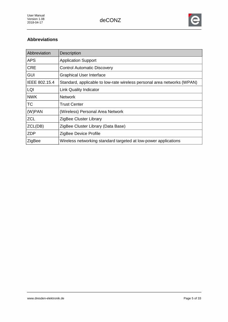
Abbreviations
Abbreviation Description
APS Application Support
CRE Control Automatic Discovery
GUI Graphical User Interface
IEEE 802.15.4 Standard, applicable to low-rate wireless personal area networks (WPAN)
LQI Link Quality Indicator
NWK Network
TC Trust Center
(W)PAN (Wireless) Personal Area Network
ZCL ZigBee Cluster Library
ZCL(DB) ZigBee Cluster Library (Data Base)
ZDP ZigBee Device Profile
ZigBee Wireless networking standard targeted at low-power applications
User Manual Version 1.08 2018-04-17
deCONZ
www.dresden-elektronik.de
Page 6 of 33
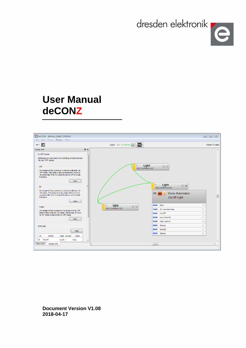
1. Overview
ZigBee is a technology which offers a powerful solution to a wide range of low-power, low-cost wireless sensor network applications. Some popular application profiles are Home Automation, Smart Energy and Health Care; beside them and other public profiles ZigBee PRO provides the possibility to easily develop special purpose applications. In many stages of a product development process it is necessary to interact with the devices in order to verify their correct operation. To achieve this in an efficient way extra PC tools are often built around the related application first for the developer and later for deployment, for operation and for maintenance. The deCONZ application from dresden elektronik is a powerful graphical tool addressing all those stages. The deCONZ provides comprehensive monitoring, control and commissioning capabilities based on the ZigBee PRO specification. The application core is kept completely generic and is therefore not limited to a specific application profile. All ZigBee application specifics like devices, profiles and clusters are described in XML files. Based on this information, the deCONZ application can generate a full functional graphical user interface for each device and any application.
2. Application
The main applications for the deCONZ application are:
Operation of ZigBee PRO networks
Device application monitoring & control
Create/remove bindings between devices
Commissioning

User Manual Version 1.08 2018-04-17
deCONZ
www.dresden-elektronik.de
Page 7 of 33
3. Getting connected
Before running a device inside a network it has to be integrated; at first it has to get connected to the host PC and then it has to be configured to be able to join the network. On Windows, Linux PC or Rasberry Pi you can use the ConBee USB Stick. On Rasberry Pi you can also use the RasBee Shield.
Figure 1: deCONZ start screen
3.1. Setting up environment
Before you can use the deCONZ application you have to set up your device and install all required software. A detailed description for this is available for ConBee1 and RaspBee2.
3.2. Connect device to PC
When starting the deCONZ application a start screen appears wherefrom a generic device can be selected and a connection to it established.
Connect the device to a PC USB port and press the button to reload the list of devices. Choose your device from the list (ConBee or RasBee) and press the Connect button.
1 <insert link here>
2 https://www.dresden-elektronik.de/fileadmin/Downloads/Dokumente/Produkte/ZLL/RaspBee-BHB-en.pdf

User Manual Version 1.08 2018-04-17
deCONZ
www.dresden-elektronik.de
Page 8 of 33
Figure 2: Generic device connected to PC
On success the start screen changes to the node view and the connection status indicates that the device is connected to the PC but not yet integrated in a network.
3.3. Create/join a network
Note: Before starting network operation the device must be configured (for details please refer to section 4).
After the device has been configured click on the Join button to create a new network (coordinator) or join an existing network (router).
Figure 3: Device connected to PC but not in a network
This process may take a few seconds until status changes from Joining to In Network (or Not Connected if an error occurs). The bars in the status icon should indicate the connection status, too.
Figure 4: The device is part of a network
User Manual Version 1.08 2018-04-17
deCONZ
www.dresden-elektronik.de
Page 9 of 33
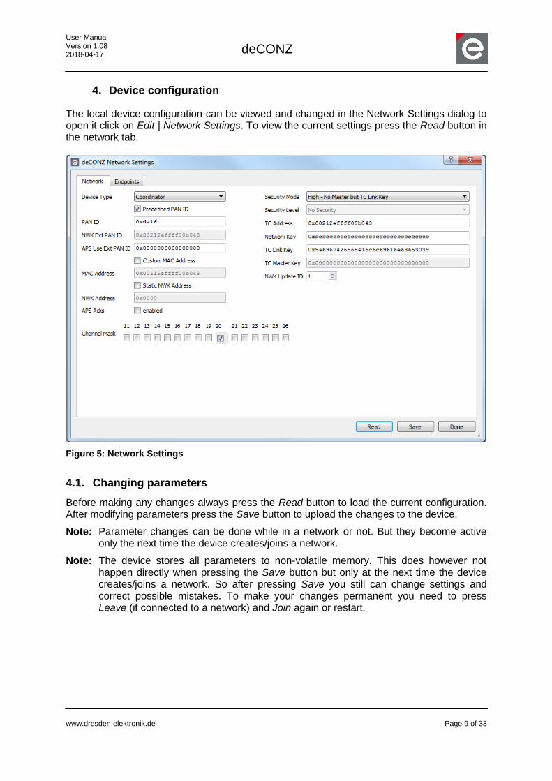
4. Device configuration
The local device configuration can be viewed and changed in the Network Settings dialog to open it click on Edit | Network Settings. To view the current settings press the Read button in the network tab.
Figure 5: Network Settings
4.1. Changing parameters
Before making any changes always press the Read button to load the current configuration. After modifying parameters press the Save button to upload the changes to the device.
Note: Parameter changes can be done while in a network or not. But they become active only the next time the device creates/joins a network.
Note: The device stores all parameters to non-volatile memory. This does however not happen directly when pressing the Save button but only at the next time the device creates/joins a network. So after pressing Save you still can change settings and correct possible mistakes. To make your changes permanent you need to press Leave (if connected to a network) and Join again or restart.

User Manual Version 1.08 2018-04-17
deCONZ
www.dresden-elektronik.de
Page 10 of 33
4.2. Parameter Description
Parameter Description Example Configuration as Coordinator
Device Type Specify if the device creates (Coordinator) or joins (Router) a network.
Coordinator
Predefined PANID
ZigBee PANIDs are dynamic by default; however it is possible to set a custom PANID here.
Yes
PANID Reflects the currently active network PANID. Any value not including 0x0000 and 0xFFFF, for example 0x1234
NWK Ext PANID
Reflects the currently active network extended PANID.
-
APS Use Ext PANID
For a coordinator this will be the extended PANID of the new network. If it is set to 0 the extended PANID will be the MAC address of the coordinator.
A router will only join a network which matches the extended PANID. If it is set to 0 the router will join any network.
0 (will be set by the device to the MAC address)
Custom MAC Address
This allows to specify a MAC address and to write it permanently to the device. The MAC address must be non-zero.
No
MAC Address
Reflects the currently set MAC address. The MAC address must be non-zero.
Will be set automatically
Static NWK Address
NWK addresses in ZigBee are dynamic by default; however it is possible to specify a static NWK address. (only Router) Note that this address must be unique for each device in the network.
No
Channel Mask
ZigBee offers 11 channels. A coordinator will search a channel from the active channels with the least interference to create a network. Routers only search active channels to join a network.
That means the mask should be identical to all devices in the network.
11,15,20,25
Security Mode
Currently the following modes are supported:
No Security
Standard - Preconfigured Network Key
Standard - Network Key from Trust Center
High – No Master but TC Link Key
High - No Master but TC Link Key
Security Level
Reflects the currently underlying security level. -
TC Address The address of the trust center. (might be the Same as MAC address
User Manual Version 1.08 2018-04-17
deCONZ
www.dresden-elektronik.de
Page 11 of 33
coordinator for example)
Network Key The global 128-bit network key. Any value not including 0
TC Link Key A link key used to retrieve the network key safely from the trust center if the security mode is set to “Standard – Network Key from Trust Center”. (and for other communication with the trust center)
0x5a6967426565416c6c69616e63653039 (the default HA link key)
TC Master Key
Used in high security. (not supported in this release)
-
APS Acks Using APS layer acknowledgments for outgoing requests of cluster info panel.
No
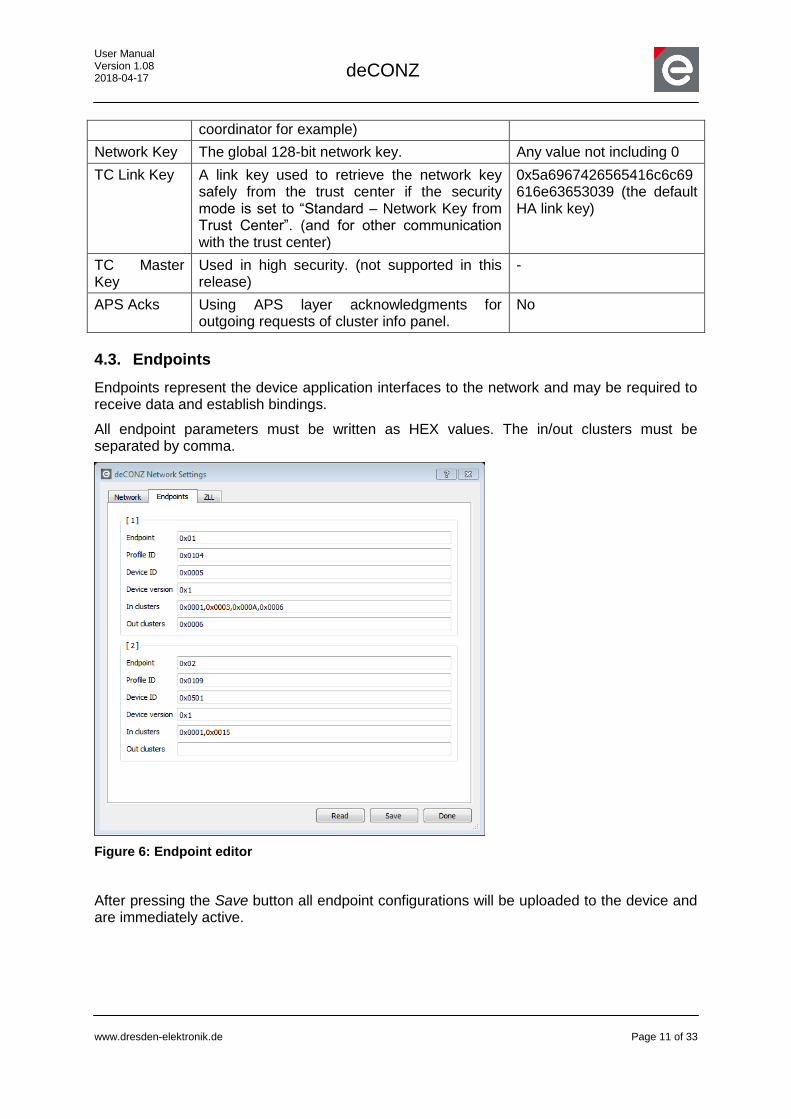
4.3. Endpoints
Endpoints represent the device application interfaces to the network and may be required to receive data and establish bindings.
All endpoint parameters must be written as HEX values. The in/out clusters must be separated by comma.
Figure 6: Endpoint editor
After pressing the Save button all endpoint configurations will be uploaded to the device and are immediately active.
User Manual Version 1.08 2018-04-17
deCONZ
www.dresden-elektronik.de
Page 12 of 33
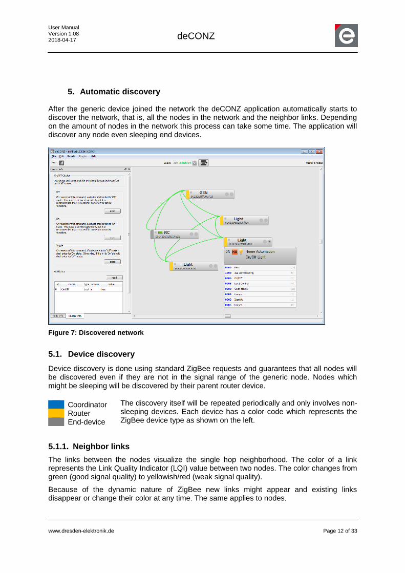
5. Automatic discovery
After the generic device joined the network the deCONZ application automatically starts to discover the network, that is, all the nodes in the network and the neighbor links. Depending on the amount of nodes in the network this process can take some time. The application will discover any node even sleeping end devices.
Figure 7: Discovered network
5.1. Device discovery
Device discovery is done using standard ZigBee requests and guarantees that all nodes will be discovered even if they are not in the signal range of the generic node. Nodes which might be sleeping will be discovered by their parent router device.
The discovery itself will be repeated periodically and only involves non-sleeping devices. Each device has a color code which represents the ZigBee device type as shown on the left.
5.1.1. Neighbor links
The links between the nodes visualize the single hop neighborhood. The color of a link represents the Link Quality Indicator (LQI) value between two nodes. The color changes from green (good signal quality) to yellowish/red (weak signal quality).
Because of the dynamic nature of ZigBee new links might appear and existing links disappear or change their color at any time. The same applies to nodes.
Coordinator Router End-device
User Manual Version 1.08 2018-04-17
deCONZ
www.dresden-elektronik.de
Page 13 of 33
5.1.2. Dynamic NWK addresses
A special case is rejoining devices. If a discovered node rejoins the network it gets a new 16-bit network address (the exceptions are static addressing and silent rejoin; there the address stays the same). The application will detect this and updates the internal address in the node cache; so all future requests to the device will use the correct address.
5.2. Service discovery
While the network device discovery only delivers the information about who is in the network, the network service discovery will figure out what a device is. As with the device discovery, this process also is handled automated by the deCONZ application.
By only using ZigBee standard requests the following information will be fetched from each node.
Descriptor Name Description
User descriptor Name or description of a node
Node descriptor Common node information
Power descriptor Information about power status and source
Simple descriptors The generic interface for each application a device runs
The user, node and power descriptors are common to all ZigBee PRO devices. The simple descriptors are individual for each node and will be discovered as follows:
Each node can provide up to 240 endpoints where each represents one application. The interfaces of the endpoints are discovered automatically by requesting the simple descriptor for each active endpoint. In order to know which endpoints are active the deCONZ application will send an active endpoints request to the node.
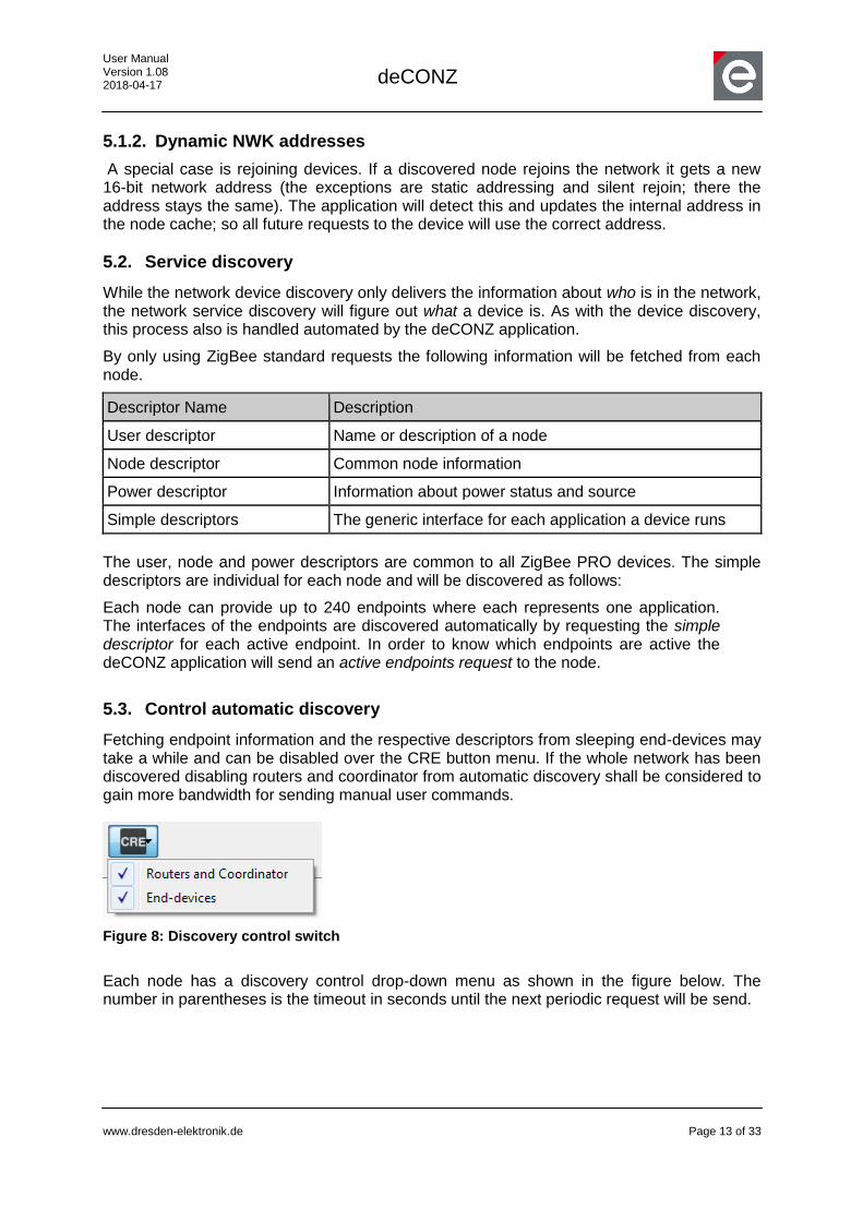
5.3. Control automatic discovery
Fetching endpoint information and the respective descriptors from sleeping end-devices may take a while and can be disabled over the CRE button menu. If the whole network has been discovered disabling routers and coordinator from automatic discovery shall be considered to gain more bandwidth for sending manual user commands.
Figure 8: Discovery control switch
Each node has a discovery control drop-down menu as shown in the figure below. The number in parentheses is the timeout in seconds until the next periodic request will be send.

User Manual Version 1.08 2018-04-17
deCONZ
www.dresden-elektronik.de
Page 14 of 33
A request can be enabled and disabled. Enabling a request will reset the timeout to 1 and the request will be sent immediately to the node.
5.4. Allow other devices to join the network
To let other devise join the network, the parameter ‘Permit Join’ can be set. Go to ‘Edit/Permit Join’ to edit this setting. The ‘Permit Join’ parameter represents the time the network stays open and allows other devices to join. A value of 0 means the network is closed. A value of 255 means the network is open. Any value between 1 and 254 is equivalent to the time in seconds the network remains open. Use the ‘Get’ button to read the actual ‘Permit Join’ value and use the ‘Set’ button to set the actual value.
Figure 10: Permit Join dialog
6. Node info panel
The user, node and power descriptors are visible over the Node Info panel. If the panel is not visible select it from the upper-left Panels menu. To display the descriptors, open the Node Info panel and click on a node. Except the name (User Descriptor) of a node all parameters are read only.
Figure 9: Discovery control menu
User Manual Version 1.08 2018-04-17
deCONZ
www.dresden-elektronik.de
Page 15 of 33
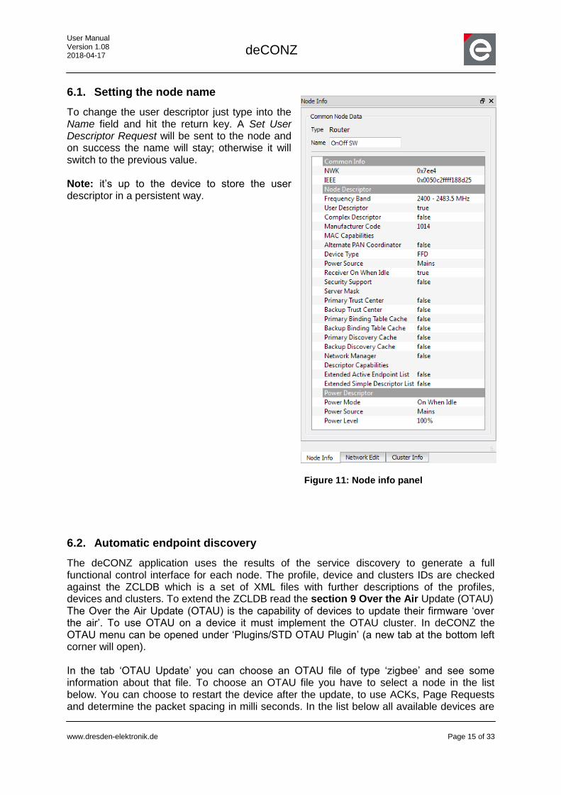
6.1. Setting the node name
To change the user descriptor just type into the Name field and hit the return key. A Set User Descriptor Request will be sent to the node and on success the name will stay; otherwise it will switch to the previous value. Note: it’s up to the device to store the user descriptor in a persistent way.
6.2. Automatic endpoint discovery
The deCONZ application uses the results of the service discovery to generate a full functional control interface for each node. The profile, device and clusters IDs are checked against the ZCLDB which is a set of XML files with further descriptions of the profiles, devices and clusters. To extend the ZCLDB read the section 9 Over the Air Update (OTAU) The Over the Air Update (OTAU) is the capability of devices to update their firmware ‘over the air’. To use OTAU on a device it must implement the OTAU cluster. In deCONZ the OTAU menu can be opened under ‘Plugins/STD OTAU Plugin’ (a new tab at the bottom left corner will open). In the tab ‘OTAU Update’ you can choose an OTAU file of type ‘zigbee’ and see some information about that file. To choose an OTAU file you have to select a node in the list below. You can choose to restart the device after the update, to use ACKs, Page Requests and determine the packet spacing in milli seconds. In the list below all available devices are
Figure 11: Node info panel

User Manual Version 1.08 2018-04-17
deCONZ
www.dresden-elektronik.de
Page 16 of 33
shown with their MAC-address, their current firmware version and the image type. While the update is running the progress and duration are also shown in that list. Click the buttons above the list to search for nodes, query the update state, start or abort the update. After a click on ‘update’ the update will start and the progress state will change and the duration will count up until the update is finished. In the tab ‘OTAU File’ you can see additional information about a firmware file.
Figure 26: STD OTAU Plugin
Extending the ZCLDB of this document.
User Manual Version 1.08 2018-04-17
deCONZ
www.dresden-elektronik.de
Page 17 of 33
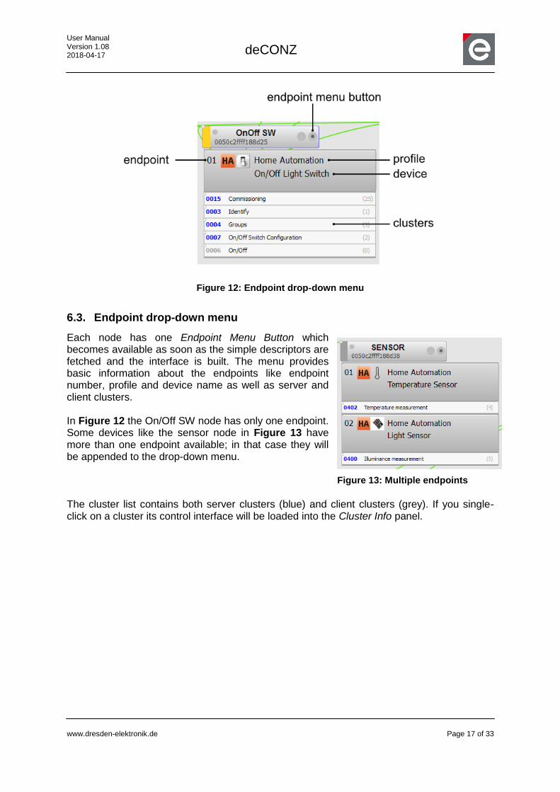
Figure 12: Endpoint drop-down menu
6.3. Endpoint drop-down menu
Each node has one Endpoint Menu Button which becomes available as soon as the simple descriptors are fetched and the interface is built. The menu provides basic information about the endpoints like endpoint number, profile and device name as well as server and client clusters. In Figure 12 the On/Off SW node has only one endpoint. Some devices like the sensor node in Figure 13 have more than one endpoint available; in that case they will be appended to the drop-down menu. The cluster list contains both server clusters (blue) and client clusters (grey). If you single-click on a cluster its control interface will be loaded into the Cluster Info panel.
Figure 13: Multiple endpoints

User Manual Version 1.08 2018-04-17
deCONZ
www.dresden-elektronik.de
Page 18 of 33
7. Cluster info panel
The control interface of a cluster (if there is one) is visible over the Cluster Info panel. If the panel is not visible select it from the upper-left Panels menu. To display a cluster open the endpoint drop-down menu of a node and click on a cluster.
7.1. Commands
The cluster Info panel provides access to all commands which are defined for a cluster. Each command has a short description saying what it does. Some commands like the Identify command (Figure 15) may take one or more parameters. In Figure 14 the identify time parameter specifies in seconds how long a device will stay in the identify mode.
7.1.1. Execute a command
Use the exec button to send the command to a node. If the command is a ZCL command and has no defined response the return state (also called default response) will be displayed beside the exec button.
Figure 14: Select and show a cluster interface
Figure 15: Command default response
User Manual Version 1.08 2018-04-17
deCONZ
www.dresden-elektronik.de
Page 19 of 33
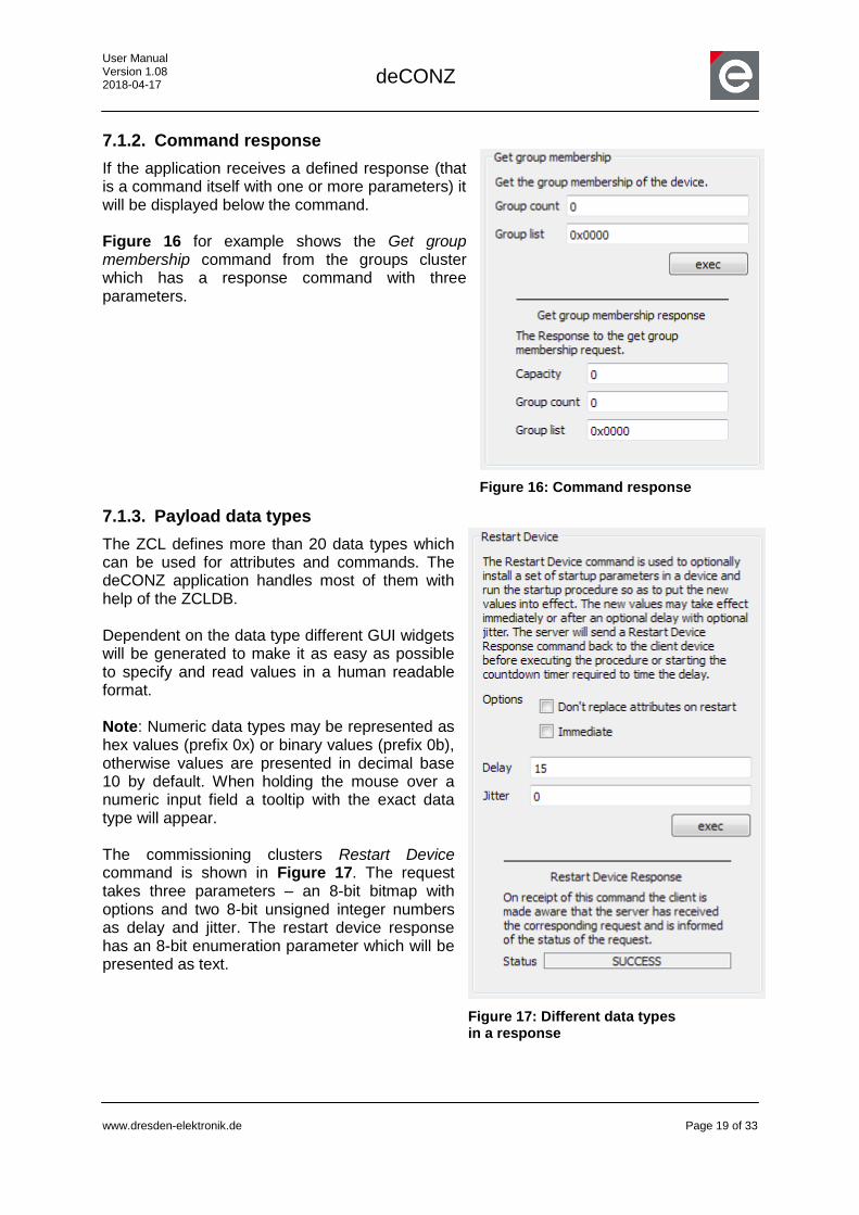
7.1.2. Command response
If the application receives a defined response (that is a command itself with one or more parameters) it will be displayed below the command. Figure 16 for example shows the Get group membership command from the groups cluster which has a response command with three parameters.
7.1.3. Payload data types
The ZCL defines more than 20 data types which can be used for attributes and commands. The deCONZ application handles most of them with help of the ZCLDB. Dependent on the data type different GUI widgets will be generated to make it as easy as possible to specify and read values in a human readable format. Note: Numeric data types may be represented as hex values (prefix 0x) or binary values (prefix 0b), otherwise values are presented in decimal base 10 by default. When holding the mouse over a numeric input field a tooltip with the exact data type will appear. The commissioning clusters Restart Device command is shown in Figure 17. The request takes three parameters – an 8-bit bitmap with options and two 8-bit unsigned integer numbers as delay and jitter. The restart device response has an 8-bit enumeration parameter which will be presented as text.
Figure 16: Command response
Figure 17: Different data types in a response

User Manual Version 1.08 2018-04-17
deCONZ
www.dresden-elektronik.de
Page 20 of 33
7.1.4. Using group- and broadcast
By default all commands are sent as unicast to the selected node only. To send a command to all nodes or a group of nodes, open the Destination Settings from the edit menu (or simply press F6).
The address and endpoint fields are filled automatically when clicking on a cluster in the endpoint dropdown menu of a node. For group cast addressing a group address must be provided by the user. Note: Remember to switch back to unicast addressing after using group or broadcasts.
7.2. Attributes
ZCL related clusters may have attributes which represent values or states. Like the command parameters attributes can have different data types which will be presented in a human readable format.
7.2.1. Reading attributes
The attributes of a cluster can be read by using the read button in the Attributes sections.
Figure 19: Attribute table
The attributes will be requested from the node. When a response is received the values will be displayed in the attribute table.
Depending on the number of attributes of a cluster multiple read attribute requests might be generated in order to read all attributes.
Some attributes are optional and may not be available. In that case the read attribute request will return unsupported attribute status. In the attribute table the description of the attribute will turn into a light grey as the Tolerance attribute in Figure 19.
Figure 18: Destination settings
User Manual Version 1.08 2018-04-17
deCONZ
www.dresden-elektronik.de
Page 21 of 33
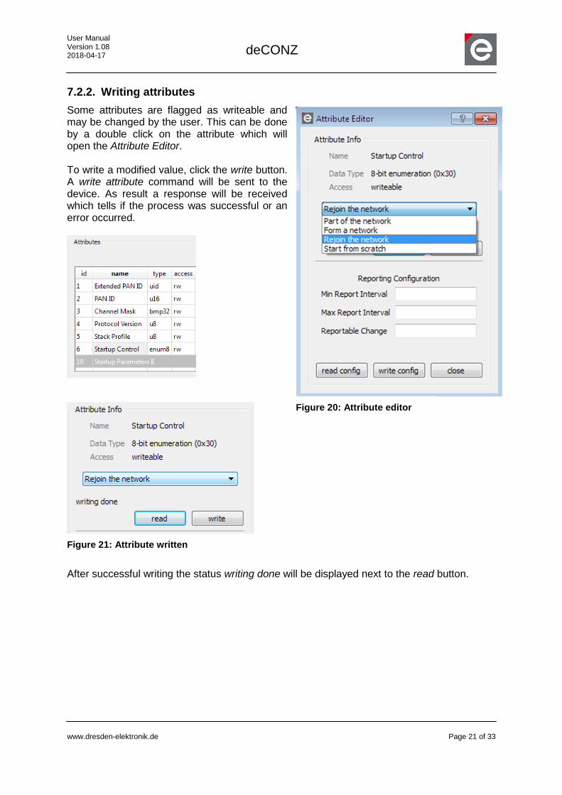
7.2.2. Writing attributes
Some attributes are flagged as writeable and may be changed by the user. This can be done by a double click on the attribute which will open the Attribute Editor. To write a modified value, click the write button. A write attribute command will be sent to the device. As result a response will be received which tells if the process was successful or an error occurred.
Figure 21: Attribute written
After successful writing the status writing done will be displayed next to the read button.
Figure 20: Attribute editor
User Manual Version 1.08 2018-04-17
deCONZ
www.dresden-elektronik.de
Page 22 of 33
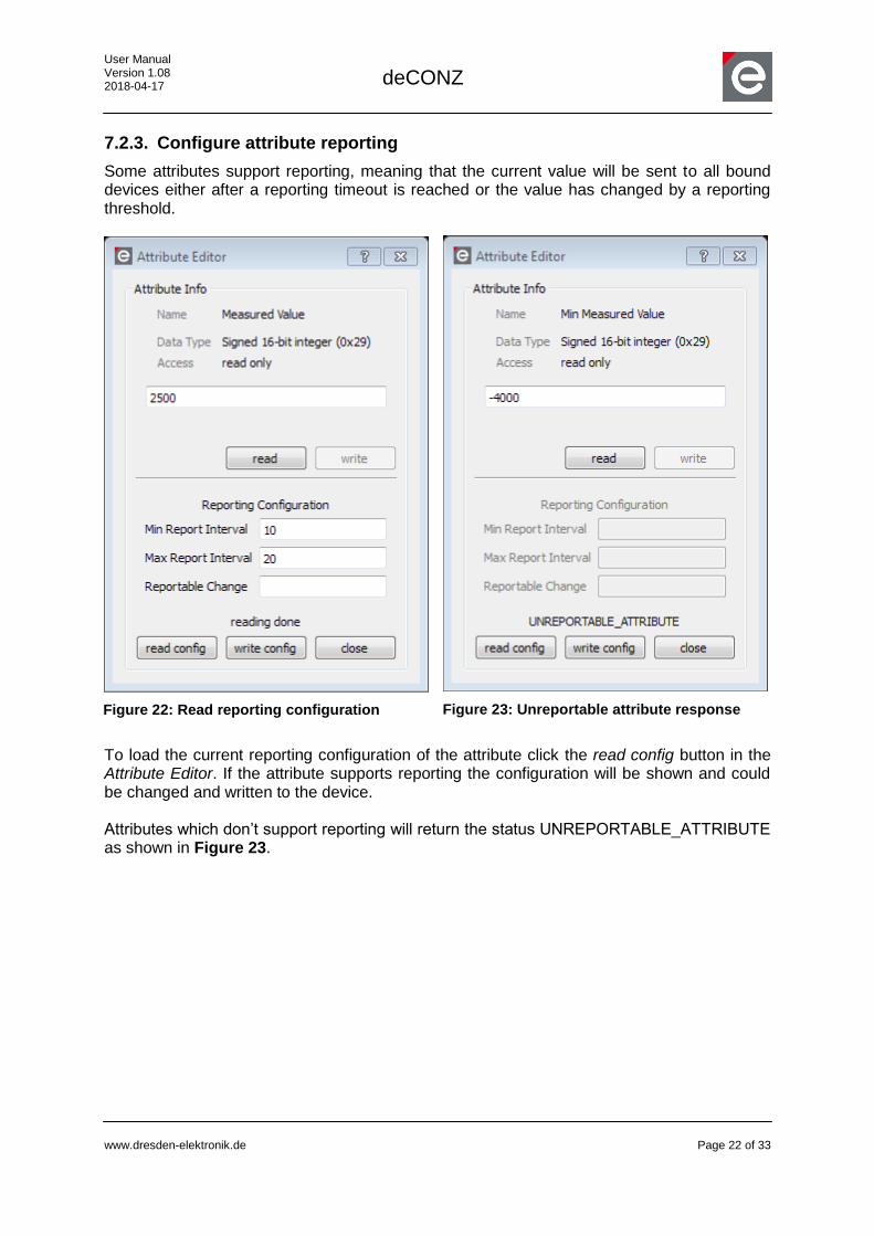
7.2.3. Configure attribute reporting
Some attributes support reporting, meaning that the current value will be sent to all bound devices either after a reporting timeout is reached or the value has changed by a reporting threshold.
Figure 23: Unreportable attribute response
To load the current reporting configuration of the attribute click the read config button in the Attribute Editor. If the attribute supports reporting the configuration will be shown and could be changed and written to the device. Attributes which don’t support reporting will return the status UNREPORTABLE_ATTRIBUTE as shown in Figure 23.
Figure 22: Read reporting configuration
User Manual Version 1.08 2018-04-17
deCONZ
www.dresden-elektronik.de
Page 23 of 33
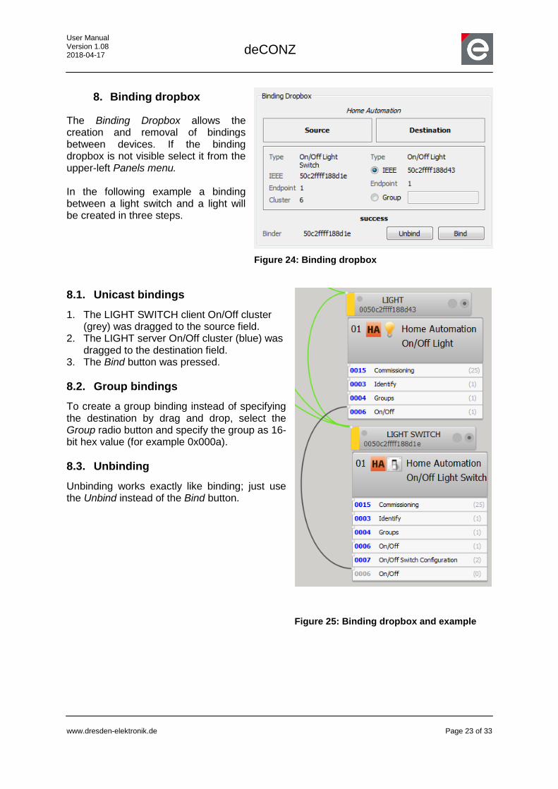
8. Binding dropbox
The Binding Dropbox allows the creation and removal of bindings between devices. If the binding dropbox is not visible select it from the upper-left Panels menu. In the following example a binding between a light switch and a light will be created in three steps.
8.1. Unicast bindings
1. The LIGHT SWITCH client On/Off cluster (grey) was dragged to the source field.
2. The LIGHT server On/Off cluster (blue) was dragged to the destination field.
3. The Bind button was pressed.
8.2. Group bindings
To create a group binding instead of specifying the destination by drag and drop, select the Group radio button and specify the group as 16-bit hex value (for example 0x000a).
8.3. Unbinding
Unbinding works exactly like binding; just use the Unbind instead of the Bind button.
Figure 25: Binding dropbox and example
Figure 24: Binding dropbox
User Manual Version 1.08 2018-04-17
deCONZ
www.dresden-elektronik.de
Page 24 of 33
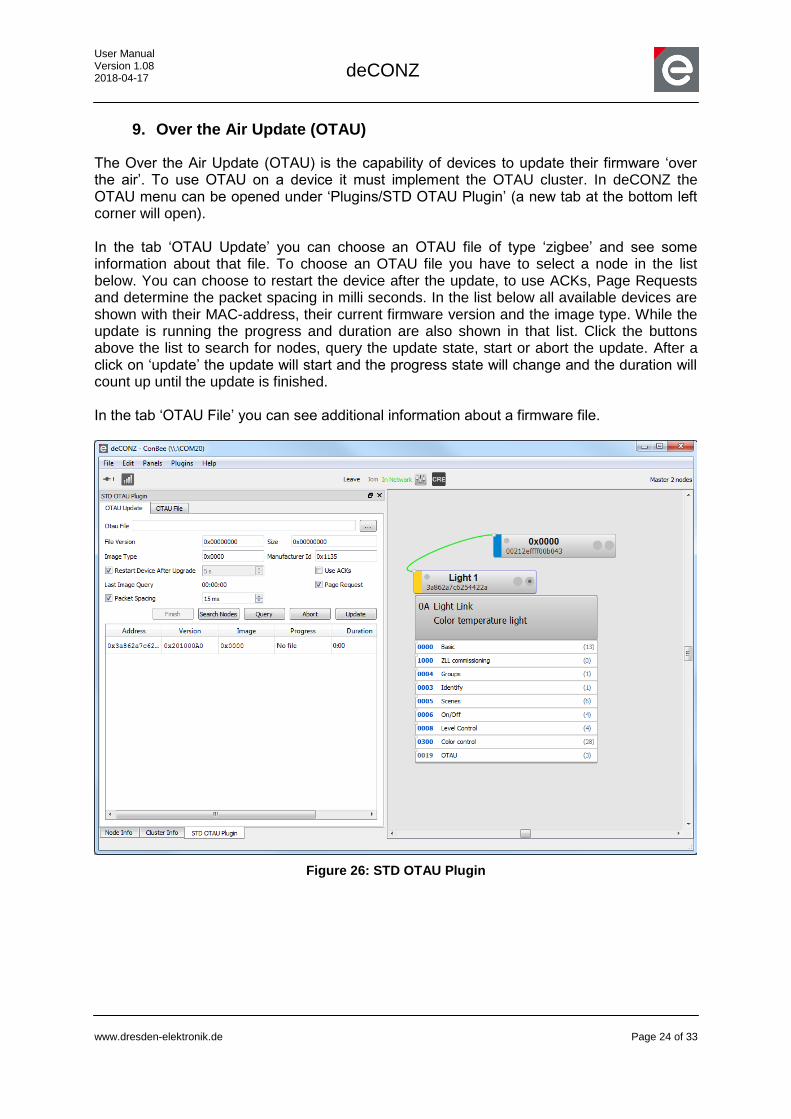
9. Over the Air Update (OTAU)
The Over the Air Update (OTAU) is the capability of devices to update their firmware ‘over the air’. To use OTAU on a device it must implement the OTAU cluster. In deCONZ the OTAU menu can be opened under ‘Plugins/STD OTAU Plugin’ (a new tab at the bottom left corner will open). In the tab ‘OTAU Update’ you can choose an OTAU file of type ‘zigbee’ and see some information about that file. To choose an OTAU file you have to select a node in the list below. You can choose to restart the device after the update, to use ACKs, Page Requests and determine the packet spacing in milli seconds. In the list below all available devices are shown with their MAC-address, their current firmware version and the image type. While the update is running the progress and duration are also shown in that list. Click the buttons above the list to search for nodes, query the update state, start or abort the update. After a click on ‘update’ the update will start and the progress state will change and the duration will count up until the update is finished. In the tab ‘OTAU File’ you can see additional information about a firmware file.
Figure 26: STD OTAU Plugin
User Manual Version 1.08 2018-04-17
deCONZ
www.dresden-elektronik.de
Page 25 of 33
10. Extending the ZCLDB
The XML structures to describe ZigBee PRO profiles and clusters which will be interpreted by the deCONZ application are kept simple and easy to understand. This section serves as introduction to enhance the shipped XML data base (which is called ZCLDB from now on) with custom or newer ZigBee PRO profiles or clusters. A ZigBee PRO profile contains various definitions about clusters, data types and logical devices. This information cannot be downloaded from the device but must be given in the ZCLDB so that the application can use this information, map clusters to it and communicate with the network devices correctly. Besides being the basis for parsing and generating ZigBee application layer messages the ZCLDB is also used to build a user friendly GUI. Every cluster interface generated by deCONZ that is shown in the cluster info panel relies on the information from the ZCLDB. Note: the ZCLDB is not necessary for the simple network discovery but for any interaction with the device.
10.1. Adding custom XML files
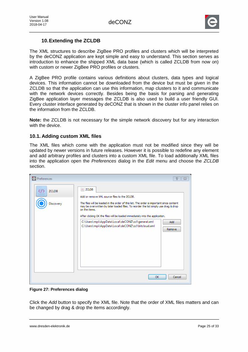
The XML files which come with the application must not be modified since they will be updated by newer versions in future releases. However it is possible to redefine any element and add arbitrary profiles and clusters into a custom XML file. To load additionally XML files into the application open the Preferences dialog in the Edit menu and choose the ZCLDB section.
Figure 27: Preferences dialog
Click the Add button to specify the XML file. Note that the order of XML files matters and can be changed by drag & drop the items accordingly.

User Manual Version 1.08 2018-04-17
deCONZ
www.dresden-elektronik.de
Page 26 of 33
After pressing the OK button, all files will be reloaded. Note: nodes which are already discovered by the application must be re-fetched in order to reflect the new ZCLDB content (Reset selected nodes by pressing F5). Otherwise the changes will only be visible after application restart.
10.2. ZCLDB profiles and functional domains
A profile contains various clusters which the ZigBee specification bundles into functional domains. A cluster is not necessarily bound to a single profile; for example clusters in the general domain are used in different profiles like Home Automation and Healthcare. In the ZCLDB shared domains are expressed by defining the domains in the first place and referencing them by name in the profiles. The attribute useZcl of a domain element should be set to true if the domain clusters are using the ZCL. If useZcl is set to false then no ZCL data frames will be generated but plain APS data frames. <domain name=“General“ description=“…“ useZcl=“true“>
<!-- Here follows the cluster list -->
</domain>
<profile id=“0x0104“ name=“Home Automation“ description=“…“ icon=“ha_profile.svg“>
<domain-ref name="General" />
<domain-ref name="Lighting" />
…
</profile>
The profile is identified by the 16-bit profile-ID. The name, description and icon attributes will be used to present a human readable interface to the user. This is a common pattern for most elements in the ZCLDB.
Table 1: The XML attributes of the domain element
XML Attribute Type Description Mandatory
name Text The domain name. Yes
description Text The domain description. No
useZcl true or false If the domain uses ZCL. If this attribute is not given ZCL will be assumed.
No
User Manual Version 1.08 2018-04-17
deCONZ
www.dresden-elektronik.de
Page 27 of 33
Table 2: XML attributes of the profile element
XML Attribute Type Description Mandatory
id 16-bit attribute-ID The profile identifier. Yes
name Text The profile name. Yes
description Text The profile description. No
icon Image The profile icon in the format svg, png or jpg
No
10.3. ZCLDB clusters
The clusters are kept in functional domains and may contain a server and client section. A cluster is identified by the 16-bit cluster-ID which will be compared against the IDs found in the simple descriptors of a device. <cluster id=“0x0003“ name=“Identify“ description=“…“>
<server>
<!-- Attributes and commands -->
</server>
<client>
<!-- Attributes and commands -->
</client>
</cluster>
Table 3: XML attributes of the cluster element
XML Attribute Type Description Mandatory
id 16-bit cluster-ID The cluster identifier. Yes
name Text The cluster name. Yes
description Text The cluster description. No
oppositeId 16-bit cluster-ID The cluster identifier of the opposite if client and server don’t share the same cluster-ID.
No
10.4. ZCLDB attributes
The server and client section of a cluster may contain one or more attributes. Attributes define how data is treated and which GUI widgets will be presented to the user. <server>
<attribute id=“0x0000“ name=“Identify Time“ type=“u16“ access=“rw“ required=“m“>
</attribute>

User Manual Version 1.08 2018-04-17
deCONZ
www.dresden-elektronik.de
Page 28 of 33
</server>
As shown in Figure 28 attributes are listed in the attribute table from the Cluster Info Panel. Table 4: XML attributes of the attribute element
XML Attribute Type Description Mandatory
id 16-bit attribute-ID The attribute identifier. Yes
name Text The attribute name. Yes
description Text The attribute description. No
type Short name of a data type The attribute data type. Yes
access Read write (rw) or read only (r)
The attribute access rights. Yes
required Mandatory (m) or optional (o) Specifies if mandatory or not. Yes
showas hex, bin, slider Specifies how the attribute will be shown. In the case that slider is used a range shall be given.
No
range Numeric range Specifies a valid range for a numeric attribute. For example range=“0,255“.
No
The attributes may contain further value-elements to describe the bits of a bitmap or an enumeration data type. The following example shows an 8-bit bitmap attribute with 3 possible flags; each bit is defined by a value element with a name and the bit position starting at 0. In the GUI the bits will be shown as checkboxes. <attribute id=“0x0002“ name=“Options“ type=“bmp8“ access=“rw“ required=“m“>
<value name=“Custom Flag 1“ value=“0“></value>
<value name=“Custom Flag 2“ value=“1“></value>
<value name=“Custom Flag 3“ value=“5“></value>
</attribute>
Figure 28: The resulting attribute table
User Manual Version 1.08 2018-04-17
deCONZ
www.dresden-elektronik.de
Page 29 of 33
Besides bitmaps enumerations could be represented as follows. In the GUI the single values will be shown in a Combobox. <attribute id=“0x0006“ name=“Startup Control“ type=“enum8“ access=“rw“ required=“m“>
<value name=“Part of the network“ value=“0“></value>
<value name=“Form a network“ value=“1“></value>
<value name=“Rejoin the network“ value=“2“></value>
<value name=“Start from scratch“ value=“3“></value>
</attribute>
10.5. ZCLDB commands
ZCL commands represent the functions of a cluster. Both server and client clusters may send and receive commands. To define a command with parameters the element payload must be used which shall contain one ZCLDB attribute definition for each parameter. <server>
<command id=”0x00” dir=”recv” name=”Identify” required=”m” description=”Start or stop …”>
<payload>
<attribute id="0x0000" type="u16" name="Identify Time" required="m"
default="5" description=”…”>
</attribute>
</payload>
</command>
<server>
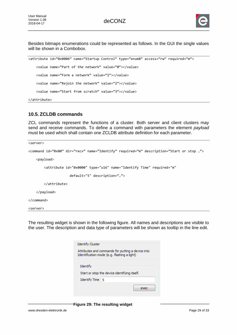
The resulting widget is shown in the following figure. All names and descriptions are visible to the user. The description and data type of parameters will be shown as tooltip in the line edit.
Figure 29: The resulting widget
User Manual Version 1.08 2018-04-17
deCONZ
www.dresden-elektronik.de
Page 30 of 33
Table 5: XML attributes of the command element
XML Attribute Type Description Mandatory
id 8-bit command-ID The command identifier. Yes
name Text The command name. Yes
description Text The command description. No
required Mandatory (m) or optional (o) Specifies if mandatory or not. Yes
dir recv or send Specifies if the command direction is to or from server or client.
Yes
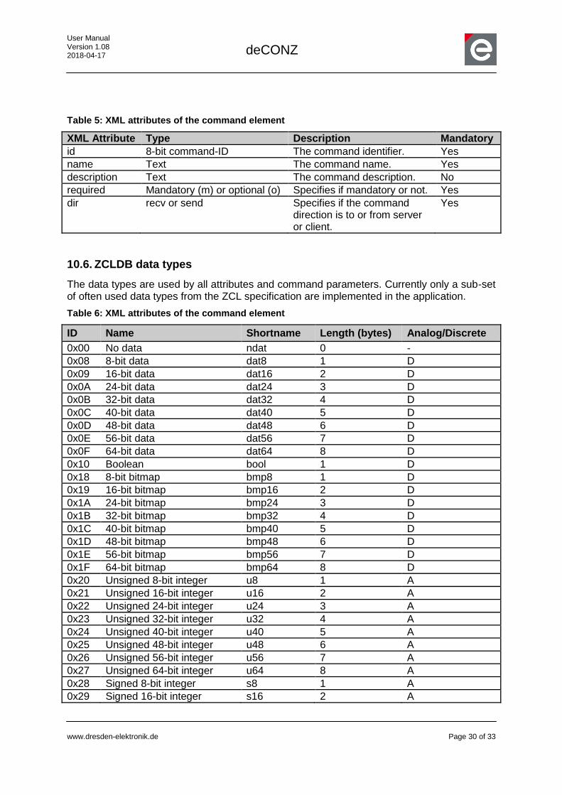
10.6. ZCLDB data types
The data types are used by all attributes and command parameters. Currently only a sub-set of often used data types from the ZCL specification are implemented in the application.
Table 6: XML attributes of the command element
ID Name Shortname Length (bytes) Analog/Discrete
0x00 No data ndat 0 -
0x08 8-bit data dat8 1 D
0x09 16-bit data dat16 2 D
0x0A 24-bit data dat24 3 D
0x0B 32-bit data dat32 4 D
0x0C 40-bit data dat40 5 D
0x0D 48-bit data dat48 6 D
0x0E 56-bit data dat56 7 D
0x0F 64-bit data dat64 8 D
0x10 Boolean bool 1 D
0x18 8-bit bitmap bmp8 1 D
0x19 16-bit bitmap bmp16 2 D
0x1A 24-bit bitmap bmp24 3 D
0x1B 32-bit bitmap bmp32 4 D
0x1C 40-bit bitmap bmp40 5 D
0x1D 48-bit bitmap bmp48 6 D
0x1E 56-bit bitmap bmp56 7 D
0x1F 64-bit bitmap bmp64 8 D
0x20 Unsigned 8-bit integer u8 1 A
0x21 Unsigned 16-bit integer u16 2 A
0x22 Unsigned 24-bit integer u24 3 A
0x23 Unsigned 32-bit integer u32 4 A
0x24 Unsigned 40-bit integer u40 5 A
0x25 Unsigned 48-bit integer u48 6 A
0x26 Unsigned 56-bit integer u56 7 A
0x27 Unsigned 64-bit integer u64 8 A
0x28 Signed 8-bit integer s8 1 A
0x29 Signed 16-bit integer s16 2 A

User Manual Version 1.08 2018-04-17
deCONZ
www.dresden-elektronik.de
Page 31 of 33
ID Name Shortname Length (bytes) Analog/Discrete
0x2A Signed 24-bit integer s24 3 A
0x2B Signed 32-bit integer s32 4 A
0x2C Signed 40-bit integer s40 5 A
0x2D Signed 48-bit integer s48 6 A
0x2E Signed 56-bit integer s56 7 A
0x2F Signed 64-bit integer s64 8 A
0x30 8-bit enumeration enum8 1 D
0x31 16-bit enumeration enum16 2 D
0x41 Octet string ostring - D
0x42 Character string cstring - D
0xE2 UTC time utc 4 A
0xE8 Cluster id cid 2 D
0xE9 Attribute id aid 2 D
0xEA BACnet oid oid 4 D
0xF0 IEEE address uid 8 D
0xF1 Security key seckey 16 D
10.7. ZCLDB devices
The definition of devices in the ZCLDB is only needed to show the name and icon of a device in the endpoint drop-down menu.
All devices must be placed in the devices-element. <devices>
<device id="0x0301" name="Thermostat" description="…" icon="dev-thermostat.png">
</device>
</devices>
Some devices might be specific to a profile. In that case the device shall be placed into the related profile element. <profile id=“0x0104“ name=“Home Automation“>
<!-- Here follows the domain refs -->
<device id="0x0333” name="Custom Device1" description="…">
</device>
</profile>
Table 7: XML attributes of the device element
XML Attribute Type Description Mandatory
id 16-bit device-ID The device identifier. Yes
name Text The device name. Yes

User Manual Version 1.08 2018-04-17
deCONZ
www.dresden-elektronik.de
Page 32 of 33
description Text The device description. No
icon Image The device icon in the format svg, png or jpg
No

User Manual Version 1.08 2018-04-17
deCONZ
www.dresden-elektronik.de
Page 33 of 33
dresden elektronik ingenieurtechnik gmbh Enno-Heidebroek-Straße 12 01237 Dresden GERMANY Phone +49 351 - 31850 0 Fax +49 351 - 31850 10 Email [email protected]
Trademarks and acknowledgements
• ZigBee is a registered trademark of the ZigBee Alliance.
• IEEE 802.15.4 is a trademark of the Institute of Electrical and Electronics Engineers (IEEE).
These trademarks are registered by their respective owners in certain countries only. Other brands and their products are trademarks or registered trademarks of their respective holders and should be noted as such.
Disclaimer
This note is provided as-is and is subject to change without notice. Except to the extent prohibited by law, dresden elektronik ingenieurtechnik gmbh makes no express or implied warranty of any kind with regard to this guide, and specifically disclaims the implied warranties and conditions of merchantability and fitness for a particular purpose. dresden elektronik ingenieurtechnik gmbh shall not be liable for any errors or incidental or consequential damage in connection with the furnishing, performance or use of this guide.
No part of this publication may be reproduced, stored in a retrieval system, or transmitted in any form or any means electronic or mechanical, including photocopying and recording, for any purpose other than the purchaser’s personal use, without the written permission of dresden elektronik ingenieur-technik gmbh. Copyright © 2012 dresden elektronik ingenieurtechnik gmbh. All rights reserved.