User Manual
123
NetSure 701 A41, NetSure 501 A41, NetSure 501 A91 Subrack Power system User Manual Version V1.0 Revision date August 29, 2012 BOM 31012653 Emerson Network Power provides customers with technical support. Users may contact the nearest Emerson local sales office or service center. Copyright © 2012 by Emerson Network Power Co., Ltd. All rights reserved. The contents in this document are subject to change without notice. Emerson Network Power Co., Ltd. Address: No.1 Kefa Rd., Science & Industry Park, Nanshan District 518057, Shenzhen China Homepage: www.emersonnetworkpower.com.cn E-mail: [email protected]
-
Upload
anh-tuan-tran -
Category
Documents
-
view
501 -
download
132
description
net
Transcript of User Manual

NetSure 701 A41, NetSure 501 A41, NetSure 501 A91
Subrack Power system User Manual
Version V1.0 Revision date August 29, 2012 BOM 31012653
Emerson Network Power provides customers with technical support. Users may contact the nearest Emerson local sales office or service center.
Copyright © 2012 by Emerson Network Power Co., Ltd.
All rights reserved. The contents in this document are subject to change without notice.
Emerson Network Power Co., Ltd.
Address: No.1 Kefa Rd., Science & Industry Park, Nanshan District 518057, Shenzhen China
Homepage: www.emersonnetworkpower.com.cn
E-mail: [email protected]

Safety Precautions
To reduce the chance of accident, please read the safety precautions very carefully before operation. The "Caution, Notice, Warning, Danger" in this book do not represent all the safety points to be observed, and are only supplement to various safety points. Therefore, the installation and operation personnel must be strictly trained and master the correct operations and all the safety points before actual operation.
When operating Emerson products, the safety rules in the industry, the general safety points and special safety instructions specified in this book must be strictly observed.
Electrical Safety
I. Hazardous voltage
Danger
Some components of the power system carry hazardous voltage in operation. Direct contact or indirect contact through moist objects with these components will result in fatal injury.
Safety rules in the industry must be observed when installing the power system. The installation personnel must be licensed to operate high voltage and AC power.
In operation, the installation personnel are not allowed to wear conductive objects such as watches, bracelets, bangles, rings.
When water or moisture is found on the Subrack, turn off the power immediately. In moist environment, precautions must be taken to keep moisture out of the power system.
"Prohibit" warning label must be attached to the switches and buttons that are not permitted to operate during installation.
Danger
High voltage operation may cause fire and electric shock. The connection and wiring of AC cables must be in compliance with the local rules and regulations. Only those who are licensed to operate high voltage and AC power can perform high voltage operations.
II. Tools
Warning
In high voltage and AC operation, special tools must be used. No common or self-carried tools should be used.
III. Thunderstorm
Danger
Never operate on high voltage, AC, iron tower or mast in the thunderstorm.
In thunderstorms, a strong electromagnetic field will be generated in the air. Therefore the equipment should be well earthed in time to avoid damage by lightning strikes.
IV. ESD
Notice
The static electricity generated by the human body will damage the static sensitive elements on PCBs, such as large-scale ICs. Before touching any plug-in board, PCB or IC chip, ESD wrist strap must be worn to prevent body static from damaging the sensitive components. The other end of the ESD wrist strap must be well earthed.
V. Short circuit
Danger
During operation, never short the positive and negative poles of the DC distribution unit of the system or the non-grounding pole and the earth. The power system is a constant voltage DC power equipment, short circuit will result in equipment burning and endanger human safety.
Check carefully the polarity of the cable and connection terminal when performing DC live operations.
As the operation space in the DC distribution unit is very tight, please carefully select the operation space.
Never wear a watch, bracelet, bangle, ring, or other conductive objects during operation.
Insulated tools must be used.
In live operation, keep the arm muscle tense, so that when tool connection is loosened, the free movement of the human body and tool is reduced to a minimum.
VI. Dangerous energy
Warning
240VA, hazardous energy, keep off, no bridge connection. This converter contains outputs exceed 240VA, when installing into end system care must be taken that the output and appropriate wire may not be touched.
Battery
Danger
Before any operation on battery, read carefully the safety precautions for battery transportation and the correct battery connection method.
Non-standard operation on the battery will cause danger. In operation, precautions should be taken to prevent battery short circuit and overflow of electrolyte. The overflow of electrolyte will erode the metal objects and PCBs, thus causing equipment damage and short circuit of PCBs.
Before any operation on battery, pay attention to the following points:
Remove the watch, bracelet, bangle, ring, and other metal objects on the wrist.
Use special insulated tools.
Use eye protection device, and take preventive measures.
Wear rubber gloves and apron to guard against electrolyte overflow.
In battery transportation, the electrode of the battery should always be kept facing upward. Never put the battery upside down or slanted.

BLVD The system has battery low voltage disconnection (BLVD) function. BLVD means when the mains fail and batteries supply power, the monitoring module cuts the load off when the battery voltage drops down to below 43.2V to prevent over-discharge. The BLVD voltage is settable. Refer to 4.2.3 Battery Selection for setting
method.
The factory setting is enabling BLVD, which means that if power outage lasts for a long time or the power system fails, there might be BLVD. Users should classify the loads and connect the priority loads to BLVD routes. For vital loads, users can disable BLVD of these loads to insure reliability of the power supply.
The method of disabling BLVD is:
Set “BLVD Enable” item of the monitoring module to “N”. Refer to 4.2.3 错误错误错误错误!!!!未找到引用源未找到引用源未找到引用源未找到引用源。。。。 for setting
method.
Notice
The advantage of enabling BLVD is protecting the batteries from over-discharge when the battery voltage is low. The disadvantage of enabling BLVD is that when the battery voltage drops down to a certain value, all the loads (including non-priority loads and priority loads) will be cut off due to battery disconnection.
The advantage of software disabling BLVD is prolonging the power supply of priority loads. The disadvantage is that software disabling cannot prevent unwanted power failure due to misoperation or power system failure.
Others
I. Sharp object
Warning
When moving equipment by hand, protective gloves should be worn to avoid injury by sharp object.
II. Cable connection
Notice
Please verify the compliance of the cable and cable label with the actual installation prior to cable connection.
III. Binding the signal lines
Notice
The signal lines should be bound separately from heavy current and high voltage lines, with binding interval of at least 150mm.

Contents
Chapter 1 Overview ............................................................................................................................................................ 1
1.1 Model Information ................................................................................................................................................. 1
1.2 Composition And Configuration ............................................................................................................................ 1
1.3 Features ................................................................................................................................................................ 4
Chapter 2 Installation Instruction ......................................................................................................................................... 5
2.1 Safety Regulations ................................................................................................................................................ 5
2.2 Preparation ........................................................................................................................................................... 5
2.3 Mechanical Installation .......................................................................................................................................... 6
2.4 Electrical Installation ............................................................................................................................................. 9
2.4.1 Power System Cabling Method ................................................................................................................. 9
2.4.2 Connecting AC Input Cables ................................................................................................................... 10
2.4.3 Connecting Load Cables ......................................................................................................................... 11
2.4.4 Connecting Battery Cables ...................................................................................................................... 11
2.4.5 Connecting Signal Cables ....................................................................................................................... 12
Chapter 3 Installation Testing ............................................................................................................................................ 16
3.1 Installation Check And Startup ............................................................................................................................ 16
3.2 Basic Settings ..................................................................................................................................................... 16
3.3 Alarm Check And System Operation Status Check ............................................................................................ 17
3.4 Final Steps .......................................................................................................................................................... 18
Chapter 4 Use Of Monitoring Module M221S、M221S ..................................................................................................... 19
4.1 Control Keypad And Indicator ............................................................................................................................. 19
4.1.1 Front Panel .............................................................................................................................................. 19
4.1.2 Indicator Function .................................................................................................................................... 19
4.1.3 Control Keypad Function ......................................................................................................................... 19
4.2 LCD Menu Tree .................................................................................................................................................. 20
4.2.1 Status ...................................................................................................................................................... 20
4.2.2 Settings.................................................................................................................................................... 21
4.2.3 Manual ..................................................................................................................................................... 28
4.2.4 ECO ......................................................................................................................................................... 28
4.2.5 Quick Setting ........................................................................................................................................... 28
4.2.6 Controller Setting ..................................................................................................................................... 29
4.3 WEB Interface Operation .................................................................................................................................... 30
4.3.1 Setting Up The Internet Explorer Web Browser ....................................................................................... 30
4.3.2 Logging Into The Controller ..................................................................................................................... 31
4.3.3 Homepage Introduction ........................................................................................................................... 32
4.4 WEB Bootloader Interface Operation .................................................................................................................. 36
4.5 Serial Bootloader Interface Operation ................................................................................................................. 37

Chapter 5 Use Of Monitoring Module M820B .................................................................................................................... 41
5.1 Operation Panel .................................................................................................................................................. 41
5.2 First Screen......................................................................................................................................................... 42
5.3 Default Main Screen ........................................................................................................................................... 42
5.4 Overall Menu Structure ....................................................................................................................................... 43
5.5 Main Menu .......................................................................................................................................................... 43
5.6 Status .................................................................................................................................................................. 44
5.7 Manual ................................................................................................................................................................ 46
5.7.1 Settings.................................................................................................................................................... 47
5.7.2 Power System Setting ............................................................................................................................. 55
5.7.3 Rectifier Setting ....................................................................................................................................... 57
5.7.4 Battery Setting ......................................................................................................................................... 57
5.7.5 Parameter Settings Of BattFuseUnit ....................................................................................................... 59
5.7.6 Parameter Settings Of DC ....................................................................................................................... 59
5.7.7 Parameter Setting Of LVD ....................................................................................................................... 59
5.7.8 AC Parameter Settings ............................................................................................................................ 60
5.7.9 Communication Parameter Settings ........................................................................................................ 60
5.7.10 Controller Parameter Settings ............................................................................................................... 60
5.8 Energy Saving Setting ........................................................................................................................................ 60
5.9 Quick Settings ..................................................................................................................................................... 61
5.10 Access M820B Through Web ........................................................................................................................... 61
5.10.1 Login ...................................................................................................................................................... 62
5.10.2 Homepage Introduction ......................................................................................................................... 63
5.10.3 Device Information ................................................................................................................................. 64
5.10.4 Data Browse, Control And Parameter Setting Of Rectifier ..................................................................... 64
5.10.5 Data Browse, Control And Parameter Setting Of Battery ...................................................................... 67
5.10.6 Alarms ................................................................................................................................................... 69
5.10.7 Maintenance .......................................................................................................................................... 70
5.10.8 Configurations ....................................................................................................................................... 78
5.10.9 Query ..................................................................................................................................................... 83
5.11 Access ACU+ Through NMS ............................................................................................................................ 85
5.11.1 NMS Supported By SNMP Agent .......................................................................................................... 85
5.11.2 MIB Installation ...................................................................................................................................... 85
5.11.3 Access ACU+ Through NMS ................................................................................................................. 86
5.11.4 ESR Configure ....................................................................................................................................... 87
Chapter 6 Alarm Handling ................................................................................................................................................. 88
6.1 Handling Alarms .................................................................................................................................................. 88
6.2 Handling Rectifier Fault ....................................................................................................................................... 89

Appendix 1 Technical And Engineering Data .................................................................................................................... 91
Appendix 2 Installation Instruction Of Battery Rack .......................................................................................................... 95
1. Installation Instruction Of Two-Layer And Four-Layer Battery Rack ..................................................................... 95
2. Installation Instruction Of Three-Layer Battery Rack ............................................................................................. 97
3. Fixing The Battery Rack ........................................................................................................................................ 98
Appendix 3 Wiring Diagram ............................................................................................................................................... 99
Appendix 4 Shematic Diagram ........................................................................................................................................ 107
Appendix 5 Glossary ....................................................................................................................................................... 115


Chapter 1 Overview 1
NetSure 701 A41, NetSure 501 A41, NetSure 501 A91 Subrack Power system User Manual
Chapter 1 Overview
This chapter introduces model description, composition and configuration, and features.
The “power system” in this manual refers to the NetSure NetSure 701 A41, NetSure 501 A41, NetSure 501 A91 series 19 subrack power system.
1.1 Model Information
Take NetSure 501 A41-S1 power system as an example, the model description is given in Figure 1-1.
NetSure 501 A 4
Region. A: Asia-Pacific region
Output power of the rectifier. 501: 1740W ~ 2000W. 701: 2900W ~ 5000W
Brand name of the power supply system
1
Version
The number of the rectifier in the typical power supply system: 4. If the number ranges between 0 ~ 9,
the character is represented by a number. If the number is larger than 9, the character isrepresented
by a letter, for example, A represents the number 10, B represents the number 11,and so on
S 1
Cabinet type: Subrack
Cabinet configuration
Figure 1-1Model information
1.2 Composition And Configuration
System composition
The system consists of power distribution parts, rectifiers and monitoring module. The rectifier model is R48-1800, R48-2900U or R48-3200 and the model of the monitoring module is M221S, M222S or M820B. The internal structures of the systems are shown in Figure 1-2 to Figure 1-6.
Figure 1-2 NetSure 501 A41- S1/S2 system structure

2 Chapter 1 Overview
NetSure 701 A41, NetSure 501 A41, NetSure 501 A91 Subrack Power system User Manual
Dummy panel
Load MCB
RectifierMonitoring module
Battery MCB
Positive terminals
Controller
AC input MCB
Figure 1-3 NetSure 501 A91-S1 system structure
Figure 1-4 NetSure 701 A41 –S2/S4 system structure
Figure 1-5 NetSure 701 A41-S1/S3/S5 system structure
Figure 1-6 NetSure 701 A41-S5 system structure
System configuration
The configurations of the power system are described in Table 1-1.

Chapter 1 Overview 3
NetSure 701 A41, NetSure 501 A41, NetSure 501 A91 Subrack Power system User Manual
Table 1-1 Configuration of fixed- configuration system
Item NetSure 501 A41-S1 NetSure 501 A41-S2 NetSure 501 A91-S1 NetSure 701 A41-S1 NetSure 701 A41-S2 NetSure 701 A41-S3 NetSure 701 A41-S4 NetSure 701 A41-S5
Contorller Model:
M221S/M222S
Model:
M820B
Model:
M221S/M222S
Model:
M221S/M222S
Model:
M221S/M222S
Model:
M221S/M222S
Model:
M820B
Model:
M221S/M222S
Rectifier
Model:
R48-1800A/R48-2000/ R48-2000e Standard
configuration:4 pieces
Model:
R48-1800A/R48-2000/R48-2000e Standard
configuration:4 pieces
Model:
R48-1800A/R48-2000/R48-2000e Standard
configuration:5
pieces
Model:
R48-2900U/R48-3000e/R48-3200/R48-3500e/R48-4000e Standard
configuration:3
pieces
Model:
R48-2900U/ R48-3000e R48- 3200 R48-3500e R48-4000e Standard
configuration:4
pieces
Model:
R48-2900U/ R48-3000e R48- 3200 R48-3500e R48-4000e Standard
configuration:4
pieces
Model:
R48-2900U/ R48-3000e R48- 3200 R48-3500e R48-4000e Standard
configuration:4
pieces
Model:
R48-2900U/ R48-3000e R48- 3200 R48-3500e R48-4000e Standard
configuration:4 个
AC power distribution
L+N+PE/ 220Vac L+N+PE/220Vac 3P+N+PE/380Vac 3P+N+PE/380Vac L+N+PE/380Vac 3P+N+PE/ 220Vac 3P+N+PE/ 380Vac L+N+PE/ 220Vac
DC power distribution
BLVD load route:
2 × 16A/1P, MCB
LLVD load route:
2 × 63A/1P, 2 × 32A/1P MCB
BLVD load route:
2 × 10A/1P, 2 × 32A/1PMCB
LLVD load route:
2 × 63A/1P, 2 × 32A/1P MCB
BLVD load route:
5 × 63A/1P, 5 × 32A/1P, 8 × 10A/1P MCB
LLVD load route:
Not configured
BLVD load route:
1 × 10A/1P MCB
LLVD load route:
4 × 40A/1P MCB
BLVD load route:
4 × 63A/1P, 6 × 32A/1P, 2 × 10A/1P MCB
LLVD load route:
Not configured
BLVD load route:
2 × 32A/1P, 2 × 16A/1P MCB
LLVD load route:
2×63A/1P,
4×32A/1P,
2×16A/1P MCB
BLVD load route:
2 × 63A/1P 4 × 32A/1P, 4 × 10A/1P MCB
LLVD load route:
2×100A/1P
2×63A/1P,
2×32A/1P MCB
BLVD load route:
2 × 32A/1P, 2 × 16A/1P MCB
LLVD load route:
2×63A/1P, 4×
32A/1P MCB
Battery MCB 2 × 63A/1P 2 × 125A/1P 2 × 125A/1P 2 × 125A/1P 2 × 125A/1P 2 × 125A/1P 2 × 125A/1P 2 × 125A/1P
AC SPD 1 piece Optional Optional Optional Optional 1 piece Optional 1 piece
DC SPD 1 piece Optional Optional Optional Optional 1 piece Optional 1 piece
Max.size (mm) 483 × 360 × 222 483 × 360 × 222 483 × 360 × 400 483 × 360 × 267 483 × 360 × 267 483 × 360 × 267 483 × 360 × 400 483 × 360 × 267
BLVD contorller mode
Contorller power-off Contorller power-on Contorller power-on Contorller power-on Contorller power-on Contorller power-off Contorller power-on Contorller power-off
Weight ≤ 25kg ≤ 25kg ≤ 25kg ≤ 25kg ≤ 25kg ≤ 25kg ≤ 25kg ≤ 25kg
Notes: 1. Temperature sensor and connected cables, remote monitoring unit, battery rack. 2. The way of outage for control is cutting off the battery, disconnecting the monitor and storage battery, monitor dropping out and communication broken up.

4 Chapter 1 Overview
NetSure 701 A41, NetSure 501 A41, NetSure 501 A91 Subrack Power system User Manual
1.3 Features
The rectifier uses the active Power Factor Compensation (PFC) technology, raising the power factor to 0.99.
Wide AC input voltage range: 85V ~ 290V (NetSure 701 A41) or 85Vac ~ 300Vac (NetSure 501 A41 & NetSure 501 A91).
The rectifier uses soft switching technology, raising the system rated efficiency to 91%, and the efficient systems can be as high as 95%.
Ultra-low radiation. With advanced EMC design, the rectifier meets international standards such as CE and NEBS. Both the conducted and radiated interference reach Class B.
The rectifier safety design complies with UL, CE and NEBS standards.
High power density.
Rectifiers are hot pluggable. It takes less than 1min to replace a rectifier.
Two over-voltage protection methods are optional: hardware protection and software protection. The latter one also has two optional modes: lock-out at the first over-voltage and lock-out at the second over-voltage.
Perfect battery management: The management functions include the LLVD (optional), BLVD, temperature compensation, auto voltage regulation, stepless current limiting, battery capacity calculation and on-line battery test, etc.
M221S and M222S support historical alarm record up to 200 and historical record up to 1000. And M820B supports historical alarm record up to 3000 and historical record up to 60000
10 sets of battery test data records.
Network design: Providing multiple communication ports (such as RS232, modem and dry contacts), which enables flexible networking and remote monitoring. M820B support the USB communication interface.
Perfect lightning protection at AC side and DC side.
Complete fault protection and fault alarm functions.
NetSure 701 A41-S3, NetSure 701 A41-S5 and NetSure 501 A41-S1 adopt the way of outage for control, This way effectively prevents the storage battery from deeply discharging after system battery protection drops out and hence prevents the unattended outdoors and indoors server rooms from the damage due to the deep discharge.

Chapter 2 Installation Instruction 5
NetSure 701 A41, NetSure 501 A41, NetSure 501 A91 Subrack Power system User Manual
Chapter 2 Installation Instruction
2.1 Safety Regulations
Certain components in this power system have hazardous voltage and current. Always follow the instructions below:
1. Only the adequately trained personnel with satisfactory knowledge of the power system can carry out the installation. The most recent revision of these safety rules and local safety rules in force shall be adhered to during the installation.
2. All external circuits that are below 48V and connected to the power system must comply with the requirements of SELV as defined in IEC 60950.
3. Make sure that the power (mains and battery) to the system is cut off before any operations can be carried out within the system subrack.
4. The power subracks shall be kept locked and placed in a locked room. The key keeper should be the one responsible for the power system.
5. The wiring of the power distribution cables should be arranged carefully so that the cables are kept away from the maintenance personnel.
2.2 Preparation
Unpacking inspection
The equipment should be unpacked and inspected after it arrives at the installation site. The inspection shall be done by representatives of both the user and Emerson Network Power Co., Ltd.To inspect the equipment, you should open the packing case, take out the packing list and check against the packing list that the equipment is correct and complete. Make sure that the equipment is delivered intact.
Cables
The cable design should meet relevant industry standards.
It is recommended to use the RVVZ cables as AC cables. The cable should reach at least +70°C temperature durability. With cable length shorter than 30 meters, the Cross-Sectional Area (CSA) calculation should be based on the current density of 3.5A/mm2. The suggested CSA value is no less than the Table 2-1.
Table 2-1 Load cable CSA selection
AC MCB rated current Max. battery current Min. cable CSA Max. cable length
125A 105A 35mm2 50mm2
100A 80A 25mm2 50mm2
63A 50A 16mm2 25mm2
The CSA of DC cable depends on the current flowing through the cable and the allowable voltage drop. To select the battery cable CSA, see Table 2-2. Select the DC load cable CSA according to the Table 2-3.
Table 2-2 Battery cable CSA selection
Battery MCB rated current Max. battery current Min. cable CSA Max. cable length (volt drop: 0.5V, with max. CSA)
125A 105A 35mm2 6 m
63A 50A 16 mm2 5 m
Note: 1. The specs are applicable at ambient temperature of 25°C. If the temperature is higher or lower than this, the CSA of the cable should be increased. 2. The battery cable should reach at least +90°C he at durability. It is recommended to use double-insulated copper-core flame retardant cable as battery cable

6 Chapter 2 Installation Instruction
NetSure 701 A41, NetSure 501 A41, NetSure 501 A91 Subrack Power system User Manual
Table 2-3 DC load cable selection
Load route rated current
Max. output current
Min. cable CSA
Max. cable length (volt drop: 0.5V, with min. CSA)
Max. cable CSA Max. cable length (volt drop:
0.5V, with max. CSA)
100A 80A 25mm2 14m 50mm2 20m
63A 50A 16mm2 9m 25mm2 14m
32A 25A 10mm2 11m 25mm2 29m
16A 12A 6mm2 14m 25mm2 48m
10A 8A 6mm2 23m 25mm2 98m
Note: The specs are applicable at ambient temperature of 25°C. If the temperature is higher than this, the CSA of the cable should be increased
To prevent the air switching capacity is too large, the load overload does not work. Recommended the capacity of the air switching is up to 1.5 ~ 2 times of the load peak.
The CSA of the system grounding cables should be consistent with the largest power distribution cables. The CSA value is no less than 25mm2.
AC and DC power distribution interface definition see Table 2-4.
Table 2-4 AC and DC power distribution interface definition
Connector name Connector specifications Wiring instructions
AC power distribution
AC input MCB H type terminal, max. cable CSA 35mm2 (Single-phase power input) H type terminal, max. cable CSA 25mm2 (Three -phase power input)
AC power line
Grounding busbar
One M8 bolt, OT type wiring terminal, max. cable CSA 35mm2 Connected to the grounding bar of the equipment room
DC power distribution
Battery output MCB
H type terminal, max. cable CSA 25mm2 (63A and below) H type terminal, max. cable CSA 50mm2 (capacity above 63A)
Connected to the battery port
Negative output MCB
H type terminal, max. cable CSA 25mm2 (63A and below) H type terminal, max. cable CSA 50mm2 (capacity above 63A)
Connected to the users load port
Positive busbar
Terminal subrack terminal:cable CSA ≤ 50mm2 Connected to the users load port
2.3 Mechanical Installation
Note
1. The cabinet or rack the subrack power supply system installed in must provide fireproof and electric protection casing, or install in cement or other difficult to burn, at the same time and other combustible materials to keep enough distance.
2. For the convenience of maintenance, users should maintain a clearance of 800mm at the front of the power supply system.
3. Subrack cannot be installed against the wall, it must leave enough space for heat dissipation.
Installed on battery bracket
1. Fix the subrack power system to the battery bracket through the connectors with M6 bolts, as shown in Figure 2-1.

Chapter 2 Installation Instruction 7
NetSure 701 A41, NetSure 501 A41, NetSure 501 A91 Subrack Power system User Manual
M6 screw
Connector
Subrack
power system
Battery
bracket
M6 screw
Connector
Figure 2-1 Cabinet and rack installation
Installed in cabient
Insert the subrack power system to the matching cabinet, as shown in Figure 2-2.
电源插框
Subrack power
system
Figure 2-2 Installed in the cabinet system
The engineering graphics of the subrack power system as shown in Figure 2-3 to Figure 2-8.

8 Chapter 2 Installation Instruction
NetSure 701 A41, NetSure 501 A41, NetSure 501 A91 Subrack Power system User Manual
Figure 2-3 Installation size of NetSure 501 A41 (unit: mm)
445
Figure 2-4 Installation size of NetSure 501 A91 (unit: mm)
Figure 2-5 Installation size of NetSure 701 A41-S1 (unit: mm)
Figure 2-6 Installation size of NetSure 701 A41-S2/S3 (unit: mm)

Chapter 2 Installation Instruction 9
NetSure 701 A41, NetSure 501 A41, NetSure 501 A91 Subrack Power system User Manual
Figure 2-7 Installation size of NetSure 701 A41- S4 (unit: mm)
265.0
438.5
482.6
Figure 2-8 Installation size of NetSure 701 A41-S5 (unit: mm)
Note
1. Tighten the captive screw of the MFU and DU Panel by the cross head screwdriver when there is no operation.
2. Also tighten the handle of the 501 modules by the cross head screwdriver.
3. Please plug in the new modules or installing a new panel after removing the rectifier module.
2.4 Electrical Installation
2.4.1 Power System Cabling Method
Cabling from the top of the power system
DU unit and MFU unit are available for the system top cover cabling.
For DU unit cabling: Cabling from the cable outlet area and then fixed to the cable-bundling plate and the top edge. As shown in Figure 2-9.

10 Chapter 2 Installation Instruction
NetSure 701 A41, NetSure 501 A41, NetSure 501 A91 Subrack Power system User Manual
Cable outlet area
Cable-bundling plate
Cable outlet area
Figure 2-9 Cable entry Illustration of the DU unit
The MFU unit cabling is shown in 2-10.
Figure 2-10 Cable entry Illustration of the MFU unit
Cabling from side of the power system
Use a cross head screwdriver to remove two screws which fix the cabling panel at side of cabling area, then the cable can be led out from the cabling area, as shown in Figure 2-11.
出线板
(出线空间)
螺钉
Figure 2-11 Side cable cabling Illustration
2.4.2 Connecting AC Input Cables
Danger
1. Switch off all MCBs before the electrical connection.
2. Only the qualified personnel can do the mains cable connection.
Take the NetSure 701 A41 power supply system as an example, the position of the terminals are shown in Figure 2-12.

Chapter 2 Installation Instruction 11
NetSure 701 A41, NetSure 501 A41, NetSure 501 A91 Subrack Power system User Manual
Figure 2-12 Illustration of the connection terminal
注意注意注意注意
若用户选用插框的交流输入采用的是端子形式,无过流和短路保护功能,则需要在插框前级配过流和接地保护器件,具体保护器件规格的选择可以咨询艾默生网络能源有限公司当地的技术支持。
2.4.3 Connecting Load Cables
Connect the negative cable of the load to the upper terminal of load MCB. Connect the positive cable of the load to the DC positive busbar, as shown in Figure 2-13.
Figure 2-13 Illustration of the load cable connection terminal
2.4.4 Connecting Battery Cables
Note
1. The batteries may have dangerous current. Before connecting the battery cables, the corresponding battery input MCBs or the battery cell connector must be disconnected to avoid live state of the power system after installation.
2. Be careful not to reverse connect the battery. Otherwise, both the battery and the power system will be damaged!
1. Connect one end of the negative battery cable to the upper terminal of battery MCBs. Connect one end of the positive battery cable to the DC positive bus bar.
2. Connect copper lugs to the other end of the battery cables. Bind the connecting parts with insulating tape, and put them beside the battery. Connect the cables to the battery when the DC distribution unit is to be tested. As shown in Figure 2-14.
Battery MCB
Positive terminal
Figure 2-14 Illustration of the battery connection terminal

12 Chapter 2 Installation Instruction
NetSure 701 A41, NetSure 501 A41, NetSure 501 A91 Subrack Power system User Manual
2.4.5 Connecting Signal Cables
There are two user interface board of the power system can optional, respectively the W2453X1 user interface board and IB2 user interface board. The W2453X1 user interface board is used together with the M221S monitoring unit or M222S monitoring unit only; and the IB2 user interface board is used together with the M820B monitoring unit only.
W2453X1 user interface board cable connection
Take the NetSure 501 A41 power supply system as an example, the position of the user connector board (W2453X1) is shown in Figure 2-15.
Figure 2-15 W2453X1 user interface board Illustration
At most two user connector boards are allowed in the power supply system. Standard cabinet is only configured with one user connector board.
With one user connector board configured, the power supply system provides three external digital signal input interfaces: DI2, DI3, DI4 (DI1 is used for DC SPD alarm. If no DC SPD is configured in the power supply system, DI1 is available) and four dry contact alarm output interfaces: DO1, DO2, DO3, DO4. With two user connector boards configured, the power supply system provides additional four dry contact alarm output interfaces: DO5, DO6, DO7, and DO8.

Chapter 2 Installation Instruction 13
NetSure 701 A41, NetSure 501 A41, NetSure 501 A91 Subrack Power system User Manual
The functions of the interfaces are shown in Table 2-5.
Table 2-5 nterface functions
Type Default alarm Description
Dry contact 1 AC power failure /
Dry contact 2 DC overvoltage or DC undervoltage Four-level DC voltage alarms
Dry contact 3 Rectifier alarm Except rectifier lost and multi-rectifier alarm
Dry contact 4 Priority LLVD /
Dry contact 5 Non-priority LLVD /
Dry contact 6 / /
Dry contact 7 / /
Dry contact 8 / /
With default settings, when the preceding alarms are generated, the contactors of the corresponding dry contacts should change their status, that is, the normally-open contactors close, and the normally-closed contactors open. All the status changes should be verified by a multimeter. After the alarms are removed, the dry contacts should resume.
The default settings of the dry contact alarms can be changed through the controller. The interfaces of the user connector board are shown in Figure 2-16.
Figure 2-16 W2453X1 user connector board interface
IB2 user interface board
The external input and output signals are all connected to the IB2 user interface board. For the ports on the IB2 user interface board, see Figure 2-17.

14 Chapter 2 Installation Instruction
NetSure 701 A41, NetSure 501 A41, NetSure 501 A91 Subrack Power system User Manual
Figure 2-17 IB2 user interface board definition
Note
1. J11 and J12 are temperature sensor ports. They are not used here.
2. J2 is I2C interface, and provides the power.
See Table 2-6 for the dry contact terminal definition.
Table 2-6 Dry contact terminal definition
Name of double-layer port Pin No. Pin name Definition
J3
1 DI1- Digital input 1-
2 DI1+ Digital input 1+
3 DI2- Digital input 2-
4 DI2+ Digital input 2+
5 DI3- Digital input 3-
6 DI3+ Digital input 3+
J4
1 DI4- Digital input 4-
2 DI4+ Digital input 4+
3 DI5- Digital input 5-
4 DI5+ Digital input 5+
5 DI6- Digital input 6-
6 DI6+ Digital input 6+
J5
1 DI7- Digital input 7-
2 DI7+ Digital input 7+
3 DI8- Digital input 8-
4 DI8+ Digital input 8+
5 NA /
6 NA /
J6
1 DO1_NC NC contact of relay 1
2 DO2_NC NC contact of relay 2
3 DO1_COM Common contact of relay 1
4 DO2_COM Common contact of relay 2
5 DO1_NO NO contact of relay 1
6 DO2_NO NO contact of relay 2
J7
1 DO3_NC NC contact of relay 3
2 DO4_NC NC contact of relay 4
3 DO3_COM Common contact of relay 3

Chapter 2 Installation Instruction 15
NetSure 701 A41, NetSure 501 A41, NetSure 501 A91 Subrack Power system User Manual
Name of double-layer port Pin No. Pin name Definition
J7
4 DO4_COM Common contact of relay 4
5 DO3_NO NO contact of relay 3
6 DO4_NO NO contact of relay 4
J8
1 DO5_NC NC contact of relay 5
2 DO6_NC NC contact of relay 6
3 DO5_COM Common contact of relay 5
4 DO6_COM Common contact of relay 6
5 DO5_NO NO contact of relay 5
6 DO6_NO NO contact of relay 6
J9
1 DO7_NC NC contact of relay 7
2 DO8_NC NC contact of relay 8
3 DO7_COM Common contact of relay 7
4 DO8_COM Common contact of relay 8
5 DO7_NO NO contact of relay 7
6 DO8_NO NO contact of relay 8
The definition of dry contact function can be set through controller or WEB browser.
The specifications of the dry contact ports are as follows:
Digital inputs: 8-route, opto-isolation, the alarm and high/low level are definable (high level: 20V ~ 60V, low level: less than 1V).
Digital output: 8-route, relay isolation, maximum: 30Vdc 1A, 125Vac 0.5A; 60W; minimum: 10uA @ 10Vdc, alarm is definable.
Connecting Communication Signal Cable
The communication port of the M221S controller is shown in Figure 2-18. The M222S only provides the RS232 communication serial port, whereas the Ethernet port is not provided.
Figure 2-18 M221S controller communication port
The communication port of the M820B controller is shown in Figure 2-19.
Figure 2-19 M820B controller communication port

16 Chapter 3 Installation Testing
NetSure 701 A41, NetSure 501 A41, NetSure 501 A91 Subrack Power system User Manual
Chapter 3 Installation Testing
This chapter introduces procedures of installation testing. The corresponding safety rules shall be adhered to in the test.
3.1 Installation Check And Startup
Before the test, inform the chief manufacturer representative. Only trained electrical engineer can maintain and operate this equipment. In operation, the installation personnel are not allowed to wear conductive objects such as watches, bracelets, bangles and rings.
During operation, parts of this equipment carry hazardous voltage. Misoperation can result in severe or fatal injuries and property damage. Before the test, check the equipment to ensure the proper earthing. Installation check must be done before testing. Then the batteries can be charged for the first time.
Make sure that the AC input MCBs, battery MCBs and load MCBs are switched off. Make sure that all the devices are properly installed.
Installation check
OK Comments Check all the MCBs and cables. Are their models correct? Check the bus bar connections, input and output cable connection, and connection between the power system and the system grounding.
Check the if the number and connections of the batteris are correct. Check the polarity of the battery string with a voltmeter.
Make sure all the cable connections are firm and reliable.
Startup preparations
OK Comments
Make sure that all the MCB are switched off. Measure the AC input voltage. Make sure the input voltage is within the allowable range. Umin=___V Check that the communication and alarm cables are connected to the signal transfer board. Check that the temperature sensor, if any, has been installed. Check that the battery string circuit is not closed. Connect the disconnected batteries to the battery string circuit Switch off unconnected battery MCBs. Check that the battery signal cables are connected to battery MCBs reliably, not loosened or suspended
Measure with a voltmeter across the connection points of each battery and make sure that the polarity is right. For a lead-acid battery with 24 cells, the voltmeter should read 2.0-2.1V/cell or 48-51V/battery. If the voltage of certain cell is lower than 2.0V, that cell must be replaced.
Umin=___V
Check with an ohmmeter that there is no short circuit between the positive & negative distribution bus bars, or between the positive & negative battery poles (Note: Pull out all modules before the check and restore them after the check)
Startup
OK Comments
Switch on the system AC input MCB. The green LED on the rectifier will be on and the fan will start running after a certain delay. The monitoring module will show that the power supply voltage is 53.5V.
Check the system voltage and busbar polarity with a voltmeter. The voltage difference between the measured value and displayed value should be less than ± 0.2V.
Start and stop each rectifier of the system by unplugging and inserting each rectifier. Check their output voltages.
3.2 Basic Settings
When the system is put into service for the first time, the parameters of monitoring module must be set based on the actual system configuration, such as battery number, capacity, user’s charge current limit and other functional requirements. Only after that can the monitoring module display system operation information and control the output.

Chapter 3 Installation Testing 17
NetSure 701 A41, NetSure 501 A41, NetSure 501 A91 Subrack Power system User Manual
OK Comments The system model has been set correctly in factory before delivery, check that the setting agrees with the actual system:
NetSure 701 A41-S1:48V/SET;Set the battery shunt coefficient for:175A/25mV;
NetSure 701 A41-S2~S5:48V/SET;Set the battery shunt coefficient for:300A/25mV;
NetSure 501 A41-S1:48V/SET;Set the battery shunt coefficient for:175A/25mV;
NetSure 501 A41-S2:48V/SET;Set the battery shunt coefficient for:300A/25mV;
NetSure 501 A91-S1:48V/SET;Set the battery shunt coefficient for:300A/25mV
The DC over-voltage alarm point has been set correctly in factory before delivery, check that the setting agrees with the actual system: Set DC over-voltage alarm: 58V
Check that the parameter Setting→Alarm Settings→Alarm mode, check that the mode is set to “High”
The battery string number set at the monitoring module should be the same as the number actually connected. (By default: 2)
Set the battery capacity according to the actual capacity of the battery connected to the system. Default: 300Ah
Configure the temperature coefficient according to the battery manufacturer’s requirement. Setting range: 0-500mV/°C. By default: 72mV/°C. (if no temp erature sensor is installed, do not set this parameter)
Set the charge current limit according to your needs. Setting range: 0.1~0.25C10. (By default: 0.1C10) Set the monitoring module according to the voltage suggested by the battery supplier. Floating Charge (FC) voltage range: 42V ~ Boost Charge (BC) voltage. Default: 53.5V. BC voltage range: FC voltage ~ 58V. By default: 56.4V. For batteries that do not need BC, set the BC voltage to FC voltage plus 0.1V
Put through the battery MCBs and connect the batteries
3.3 Alarm Check And System Operation Status Check
Alarm check
Check that all functional units can trigger alarms that can be displayed on the monitoring module.
OK Comments
Pull out one rectifier. The “Rect N Com Failure” alarm should be triggered. Insert the rectifier in. The alarm should disappear. Repeat the same procedures on other rectifiers.
Remove battery MCB 1. The “Batt1 Failure” alarm should be triggered. Put on the MCB. The alarm should be cleared. Repeat the same on battery MCB 2.
Switch off a load MCB connected to a load route. The alarm “Load N Failure” should be triggered. Switch on the MCB, and the alarm should be cleared. Repeat the same on the other load MCBs.
Remove all the battery input MCBs. Keep only one rectifier in operation. Through the monitoring module, adjust the rectifier FC voltage to make it lower than the alarm point. The alarm “DC Voltage Low” should be triggered.
Keep the rectifiers in operation. Set through the monitoring module the battery management parameter to “Manual”. Enter the maintenance menu at the monitoring module. Select “Disconnect” and confirm it. The battery protection contactor should be open, and the “BLVD” alarm should be displayed at the monitoring module.
Note: when the preceding alarms are generated, the monitoring module will give alarms after approximately 3s.
System operation status check
There should be no alarms during normal system operation. The system operation status check can be conducted through the monitoring module.
OK Comments Check that the system type agrees with the actual system when the system operates The monitoring module should display the correct AC voltage. The monitoring module should be able to display the DC voltage. The difference between the displayed voltage and that measured at the bus bar should be less than 1%.
The monitoring module should display the battery current. The difference between the displayed and measured battery current should be less than 1%.
Check the number of the rectifier through the monitoring module. The number should be consistent with the actual number.
Check the voltage, current, current limiting point of rectifiers through the monitoring module. They

18 Chapter 3 Installation Testing
NetSure 701 A41, NetSure 501 A41, NetSure 501 A91 Subrack Power system User Manual
OK Comments
should agree with the actual parameters. For the system configured with temperature sensor, the monitoring module should be able to display the battery ambient temperature. Hold the probe of the temperature sensor with hand and watch the monitoring module, which should diplay the change of temperature.
3.4 Final Steps
OK Comments
Disconnect all test equipment from the system and make sure that materials irrelevant to the equipment have been all removed.
Restore the equipment to its original condition and close the cabinet door. Check and handover the equipment that the user has purchased. Note down all the operations taken, including time of the operation and name of the operator.
If any defect is found in this equipment, inform the personnel responsible for the contract.
If repairing is needed, please fill in the FAILURE REPORT and send the report together with the defective unit to the repairing center for fault analysis.

Chapter 4 Use Of Monitoring Module M221S、M221S 19
NetSure 701 A41, NetSure 501 A41, NetSure 501 A91 Subrack Power system User Manual
Chapter 4 Use Of Monitoring Module M221S 、、、、M221S
This chapter introduces the front panel and functional keys briefly, and expounds screen contents, access method, system controlling, information querying and parameter setting.
After the monitoring module is powered on, the language selection screen will pop up, and the monitoring module is initialized. The default language is Chinese. After the initialization, the first system information page will appear.
4.1 Control Keypad And Indicator
4.1.1 Front Panel
There are backlit LCD display, functional keypad, indicators and positioning pin on the front panel of M500D monitoring module, as shown in figure 4-1.
Figure 4-1 Front panel of M500D monitoring module
4.1.2 Indicator Function
The function of the indicators is shown in table 4-1.
Table 4-1 Functions of Indicators
Indicator Normal State Fault State Fault Cause
Status (green) On Off If this LED is on, this means the system is operating normally
Observation Alarm (yellow)
Off On The power system has one or more active observation alarms. Alarm conditions are programmable. Refer to Table 3-3 for defaults
Major Alarm (red)* Off On The power system has one or more active major alarms (Major and Critical Alarms). Alarm conditions are programmable. Refer to Table 3-3 for defaults
Note: A Major Alarm initiates an alarm report if alarm report is enabled
4.1.3 Control Keypad Function
The function of the control keypad is shown in table 4-2.
Table 4-2 Function of Keys on the Panel
Key Symbol Key Name Function
ENT Enter Confirm or Execute
Up Move Up Cursor or Select the Previous Screen
Down Move Down Cursor or Select the Next Screen
ESC Escape Escape or Cancel
20 Chapter 4 Use Of Monitoring Module M221S、M221S
NetSure 701 A41, NetSure 501 A41, NetSure 501 A91 Subrack Power system User Manual
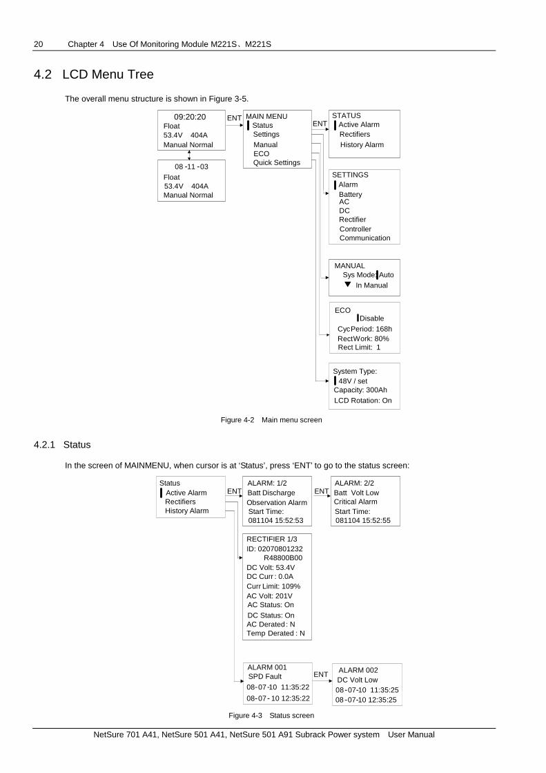
4.2 LCD Menu Tree
The overall menu structure is shown in Figure 3-5.
09:20:20Float53.4V 404AManual Normal
08 -11 -03
Float53.4V 404AManual Normal
ENT MAIN MENUStatusSettings
ECOManual
Quick Settings
ENTSTATUS
Active AlarmRectifiersHistory Alarm
SETTINGSAlarm
Rectifier
BatteryACDC
ControllerCommunication
Disable
CycPeriod: 168hRectWork: 80%
MANUALSys Mode: Auto
In Manual
System Type:48V / set
Capacity: 300Ah
ECO
Rect Limit: 1
LCD Rotation: On
Figure 4-2 Main menu screen
4.2.1 Status
In the screen of MAINMENU, when cursor is at ‘Status’, press ‘ENT’ to go to the status screen:
Active AlarmRectifiersHistory Alarm
ENTALARM: 1/2Batt DischargeObservation AlarmStart Time:081104 15:52:53
RECTIFIER 1/3ID: 02070801232
R48800B00DC Volt: 53.4VDC CurrCurr Limit: 109%AC Volt: 201VAC Status: On
DC Status: OnAC Derated : NTemp Derated : N
ALARM 001SPD Fault
08-07-10 11:35:22
08-07- 10 12:35:22
ENTALARM: 2/2Batt Volt LowCritical AlarmStart Time:081104 15:52:55
ALARM 002DC Volt Low08-07-10 11:35:2508 -07-10 12:35:25
ENT
Status
: 0.0A
Figure 4-3 Status screen

Chapter 4 Use Of Monitoring Module M221S、M221S 21
NetSure 701 A41, NetSure 501 A41, NetSure 501 A91 Subrack Power system User Manual
In the status screen, you can move the cursor to ‘Active Alarm’, ‘Rectifiers’, and ‘History Alarm’ respectively and press ‘ENT’ to check the information of active alarm, rectifiers, and history alarm. The rectifier screen shows the information of first rectifier, if you want see the information of next rectifier, just press ‘ENT’. In screen of ‘Active Alarm’, ‘Alarm 1/2’, ‘1/2’ means there are 2 active alarms and this screen is displaying the first active alarm. The alarm level and alarm start time are displayed in the screen
In the screen of ‘History Alarm’, the ‘ALARM 001’ means this screen is displaying the first history alarm. The alarm start time and end time are displayed in the screen.
4.2.2 Settings
In the Main Menu screen, move the cursor to the item of ‘Setting’ and press ‘ENT’ to enter the Setting menus. Before you access the Setting menu, the system will require you to enter the password first. Method of entering password:
For example, to enter the password of ‘640275’: Press ‘ENT’, and the bit will be highlighted, now you can press or continuously to enter the numbers from 0 to 9, or enter the letters from ‘a’ to ‘z’ or from capital letter ‘A’ to ‘Z’. After entering ‘6’, press ‘ENT’ and the cursor will move to the next bit, and in the same way, press or continuously to enter ‘4’, and you can enter the rest bits ‘0275’ in the same way.
SETTINGSAlarm
Rectifier
BatteryACDC
ControllerCommunication
ALARMAlarm LevelAlarm ControlDI Setting
COMMUNICATIONAddress: 1CommMode : RS232Protocol: YDN23BaudRate: 9600IP/Subnet/Gate:
10.163.210.91255.255.255.010.163.210.1
CallbackTime: 3PhoneNumber:8601067786010808
RECTIFIERPosition: DisablR -Posi: 1-1HVSD: 59.0VDefault V: 53.5VWalk-in On: NWalk-in T: 8sInterval T: 0sAC OverV On: NACCurrLim : 30A
BATTERYBasic
ChargeTestTemp Comp
ACOver Volt: 280VUnder Volt: 180VPH Fail: 80VAC Input: NAC PH: 3-PH
DCOver Volt2: 58.2VOver Volt1: 58.5VUnder V1: 45.0VUnder V2: 45.0VAmb High: 40CAmb Low: -5C
CONTROLLERLang: EnglishTzone: GMT + 08:00Date: 2009-03-23Time: 22:17:18System Type:
48V/1000ADownloadMode:NReset PWD: NReset Para: NOper1PWD: ******Oper2PWD: ******AdminPWD: ******
LVD
Figure 4-4 Settings screen

22 Chapter 4 Use Of Monitoring Module M221S、M221S
NetSure 701 A41, NetSure 501 A41, NetSure 501 A91 Subrack Power system User Manual
In the Setting menu, there are 7 items that are ‘Alarm’, ‘Rectifier’, ‘LVD’, ‘AC’, ‘DC’, ‘Controller’ and ‘Communication’ respectively.
Move the cursor to ‘Rectifier’ and press ENT, you ca n configure the following rectifier parameters:
Position: Enable or disable the shelf setting.
R-Posi: rectifier position in shelf.
HVSD: high voltage shut down, rectifier will shut down when its output voltage exceeds this HVSD point.
Default V: rectifier default output voltage.
Walk-in ON: rectifier walk-in function (soft start) is enabled.
Walk-in T: rectifier walk-in time (soft start time).
Interval T: rectifier sequential startup interval.
AC OverV on: rectifier will shutdown when AC input exceeds AC over voltage point.
ACCurrLim: rectifier current limiting value during startup process.
Move the cursor to ‘AC’ and press ENT, you can confi gure the following AC parameters:
Over Volt: set the over voltage protection point.
Under Volt: set the under voltage protection point.
PH Fail: set the phase failure voltage point.
AC PH: can set the AC input to 3-phase or single phase (‘1-PH’).
Move the cursor to ‘DC’ and press ENT, you can confi gure the following DC parameters:
Over Volt2: set the over voltage protection point2.
Over Volt1: set the over voltage protection point1.
Under V1: set the DC output under voltage point 1.
Under V2: set the DC output under voltage point 2.
AmbHigh: set the high ambient temperature.
AmbLow: set the low ambient temperature.
Move the cursor to ‘Controller’ and press ENT, you c an configure the following controller parameters:
Lang: set the display language of LCD, you can select English or your local language.
Tzone: set the time zone.
Date: set the current date.
Time: set the current time.
System Type: set the system type.
DownloadMode: enter the download mode through serial port.
Reset PWD: Reset the password to default.
Reset Para: Reset parameters to default.
Oper1PWD: set the password of operator 1.
Oper2PWD: set the password of operator 2.
AdminPWD: set the password of administrator.
There are three levels password. Default passwords: 1 for operator1, 2 for operator2, and 640275 for administrator. Only administrator can transfer to serial and web download mode and reset the password. Operator2 can change the system type and reset the parameters.
Move the cursor to ‘Alarm’ and press ENT, you can enter the alarm menus:

Chapter 4 Use Of Monitoring Module M221S、M221S 23
NetSure 701 A41, NetSure 501 A41, NetSure 501 A91 Subrack Power system User Manual
AlarmAlarm LevelAlarm ControlDI Setting
ALARM LEVELAlarm BlockSeverity:Observation AlarmOut Relay: 0
ALARM LEVELSPD faultSeverity:Major AlarmOut Relay: 0
ALARM LEVELLFuse AlarmSeverity:Critical AlarmOut Relay: 6
ENT ENT ENT
ALARM CONTROLAlm Voice: OpenClear: History
DI SETTINGSDI NO.: 1Digital1 AlarmActive: High
Figure 4-5 Alarm screen
Alarm level setting
In the submenu of alarm level setting, move cursor before ‘Alarm Block’, press ‘ENT’, then you can set the alarm levels of other alarms such as ‘SPD fault’, ‘LFuse Alarm’, ‘Digital3 Alarm’, etc.
In the submenu of alarm level setting, you can set the alarm level of each alarm to observe alarm, major alarm, or critical alarm. You can also set the output relay number that outputs the alarm signal.
The characteristics of 4 alarm categories are given in the following table:
Table 4-3 characteristics of 4 alarm categories
Alarm levels
Red alarm indicator of
controller and system
Yellow alarm indicator of
controller and system
Alarm buzzer Alarm report Remark
CA (critical alarm)
On On Yes Alarm report is enabled
MA (major alarm)
On On Yes Alarm report is enabled
OA (observation alarm)
On Off No
No alarm Off Off Off No
Note:
1. The alarm levels of temperature sensor disconnected alarm and temperature sensor failure alarm, and the corresponding relay output cannot be set through the LCD. The alarm levels of these two alarms and the corresponding relay are the same with those of the high temperature alarm setting.
2. If the analog alarm has two levels of alarm thresholds, and if these two alarm thresholds are set to the same value, then the second level will be cancelled and the first level of the alarm will be displayed in LCD. For example: If the alarm threshold of ‘high temperature 1’ is set to the same with the threshold of ‘high temperature 2’, and if this threshold is set to 40 deg C, then when the temperature exceeds 40 deg C, the system will only issue ‘high temperature 1 alarm’, and will not issue the ‘high temperature 2 alarm’.
In the alarm level setting submenu, you can also set the output relay no. for the corresponding alarm.
Alarm control menu
For the submenu of ‘AlmVoice’ of alarm control menu, you can set it to ‘Open’(audible alarm is enabled) or ‘Close’ (no audible alarm), and you can also set the time of audible alarm and the time can be ‘3min’, ‘10min’, ‘1h’ and ‘4h’.
For the submenu of ‘Block Alarm’, you can set ‘Y’ or ‘N’ to select whether the alarm should be blocked or not.
For the submenu of ‘Clear’, you can select ‘History’, ‘ECOFail’, ‘Maintain’, ‘ShortTest’, ‘TestFail’ ,’Rect Lost’ ‘Rect Commb’ and ‘Rect Not respond’ to clear corresponding alarm.

24 Chapter 4 Use Of Monitoring Module M221S、M221S
NetSure 701 A41, NetSure 501 A41, NetSure 501 A91 Subrack Power system User Manual
DI SETTINGS
All the alarms can be configured with No.1 to No.8 alarm contacts. ‘0’ means no alarm dry contacts. All the alarm dry contacts provide NC (normally closed) or NO (normally opened) output and the default alarm dry contacts are given in the following table.
Table 4-4 Default alarm dry contact setting
Dry contact No. Default alarm
Dry contact 1 Mains Failure
Dry contact 2 DC Under Volt or DC Over Volt
Dry contact 3 Rectifier alarm
Dry contact 4 LVD2
Dry contact 5 LVD1
Dry contact 6 None
Dry contact 7 None
Dry contact 8 None
Table 3-5 lists the alarms that you can scroll through in the ALARM SETTINGS/ALARM LEVEL menu, and also shows their factory default ‘Alarm Level’ and ‘Mapped Output Relay’ settings.
Table 4-5 Controller Alarms and Factory Default Settings
Alarm name Alarm description Condition Default alarm level Default mapped
output relay
Alarm Block Alarm Block Alarms are blocked by the LCU+ Observation
Batt Imbalance
Batt Imbalance Battery middle voltage out of the range of ( bus voltage /2) ± 0.6
Major
SavePowerFault
SavePowerFault Into and out of save power status for 5 times in one hour
Major
Save Power Save Power Function System is in save power status Observation
AC High AC Voltage High Input phase voltage higher than AC High point Observation
AC Low AC Voltage Low Input phase voltage lower than AC Low point Observation
AC PH Fail AC Phase Fail Input phase fails Observation
Temp High2 Temperature High 2 Ambient/ Battery temperature higher than Temperature High 2
Major
Temp High1 Temperature High1 Ambient/ Battery temperature higher than normal operation range
Major
Temp Low Temperature Low Ambient/ Battery temperature lower than normal operation range
Observation
Batt Over Chg
Battery Over Charge The charging current over the maximum value Observation
DC Volt High+
DC Voltage High+ System output voltage much higher than float charge voltage
Critical 2
DC Volt High DC Voltage High System output voltage higher than float charge voltage
Critical 2
DC Volt Low DC Voltage Low System output voltage slightly lower than float charge voltage
Critical 2
DC Volt Low- DC Voltage Low- System output voltage is much lower than float charge voltage
Critical 2
Rect HVSD Rectifier HVSD Rectifier HVSD circuit activated Major 3
Rect LoadShare
Rectifier LoadShare
The difference between rectifier output current and average output current larger than 8A (+/-4A), and the load of the rectifier greater than 10% of its capacity
Observation 3
Rect Derated Rectifier Derated The output power of at least one rectifier is derated because of AC undervoltage or overtemperature
Observation 3
Rect Fan Fails
Rectifier Fan Fails Fan of at least one rectifier fails Major 3
Rect Protect Rectifier Protect AC input voltage out of the range of 85Vac to 295Vac results in at least one rectifier protected
Observation 3

Chapter 4 Use Of Monitoring Module M221S、M221S 25
NetSure 701 A41, NetSure 501 A41, NetSure 501 A91 Subrack Power system User Manual
Alarm name Alarm description Condition Default alarm level Default mapped
output relay
Rect Failure Rectifier Failure Serious load sharing alarm (the output current of the rectifier is lower than 1A, and the average load is greater than 10% of the total rectifier capacity)
Critical 3
Rect TempHigh
Rectifier Temperature High
High temperature protection activated in at least one rectifier
Major 3
Rect AC Fail Rectifier AC Fail AC input voltage lower than 80Vac Major 3
Rect Comm Fail
Rectifier Communication Fail
Rectifier(s) unable to communicate with LCU+ Major 3
MultiRect Alarm
Multi rectifier Alarm Two or more rectifiers have alarms Critical
System Maintain
System Maintain System has not been maintained within preset maintenance time
None
Rect Lost Rectifier Lost Rectifier reduction detected Critical
Rect OverLoad
Rectifier OverLoad Total load current greater than the High Load value Observation
Mains Failure
Mains Failure AC input voltage lower than 80Vac Major 1
LVD2 LVD2 LVD contactor 2 open due to low battery voltage Critical 4
LVD1 LVD1 LVD contactor 1 open due to low battery voltage Critical 5
Batt Test Fail Battery Test Fail Battery discharge test failure (battery voltage is lower than setting value before test time is reached)
Observation
DC Volt Fail DC Voltage Fail The difference between bus voltage and the set output voltage larger than the set value
Observation
Curr Imbalance
Current Imbalance The total output current not equal to the sum of the battery current and the load current
Observation
Batt Discharge
Battery Discharge Batteries are discharging Observation
Batt Test Battery Test The batteries are testing None
Boost Charge
Boost Charge The batteries are in boost charge state None
Manual Mode
Manual Mode The system is in manual mode Observation
SelfDetect Fail
SelfDetect Fail LCU+ detects error in hardware self test Observation
LVD2Ctrl Fail LVD2 Control Fail After battery disconnection/ connection signal is sent out, the feedback signal of the contactor is false
Critical
BattFuse Fail
Battery Fuse Fail Battery fuse(s) or circuit breaker(s) open Critical
LoadFuse Fail
Load Fuse Fail Distribution (load) fuse(s) or circuit breaker(s) open Critical
Digital4 Digital4 User programmable Major
Digital3 Digital3 User programmable Major
Digital2 Digital2 User programmable Major
Digital1 Digital1 User programmable Major
SPD SPD SPD signal interrupted Major

26 Chapter 4 Use Of Monitoring Module M221S、M221S
NetSure 701 A41, NetSure 501 A41, NetSure 501 A91 Subrack Power system User Manual
Move the cursor to ‘Battery’ to set the battery parameters:
BATTERYBasic
ChargeTestTemp Comp
Sys Mode: AutoBattFuse : 2Capacity: 600Ah
ENT
Float: 51.8VBoost: 57.6VLimit: 0.100COver: 0.300CAuto Boost:- Enable-Current: 0.060C- Capacity: 80.0%Const Boost:- Curr: 0.01C- Time: 180minCyc Boost:
- Enable-Period: 2400h-Time: 720minBoost Limit Time:1080min
End Test- Volt: 45.2V- Time: 300min- Capacity: 0.70CCyc Test: DisablCyc Test Time:01-01 00:0004-01 00:00
Short Test:
- Alarm 10A- Period: 1h- Time: 1minConCurr Test:- Enable: No- Current: 9999A
Temp1: NTemp2: N
Batt T H2: 50CBatt T H1: 50CBatt T L1: 0C
LVD1: EnblLVD2: EnblLVD1 Volt: 44.0VLVD2 Volt: 43.2V
LVD
Bat. Shunt: YShunt Coeff-Current: 500A-Volt: 25mV
Center Temp: 25CCoeff : 72mV / C
- Enable: No
07-01 00:0010-01 00:00
Figure 4-6 Battery screen
Move cursor to ‘Basic’, you can configure the follo wing parameters:
Sys Mode: set the system mode from ‘Auto’ to ‘Manual’ or from ‘Manual’ to ‘Auto’.
Method of changing ‘Auto’ to ‘Manual’:
As shown in screen of ‘Basic’, in the item of ‘Sys Mode’, press ‘ENT’ to highlight ‘Auto’, and then press or to change it into ‘Manual’, and then press ‘ENT’ again to validate the change.
BattFuse: set the number of battery fuses.
Capacity: Set the battery capacities.
Bat. Shunt: set if battery shunt is configured.
Shunt Coeff: set current and voltage coefficients.
Move cursor to ‘LVD’, you can configure the followin g parameters:
LVD1: Enable or disable LVD1.
LVD2: Enable or disable LVD2.
LVD1 Volt: set the voltage point at which the LVD1 contactor disconnects.
LVD2 Volt: set the voltage point at which the LVD2 contactor disconnects.
Move cursor to ‘Charge’, you can configure the foll owing parameters:
Float: set the float charging voltage.
Boost: set the boost charging voltage.

Chapter 4 Use Of Monitoring Module M221S、M221S 27
NetSure 701 A41, NetSure 501 A41, NetSure 501 A91 Subrack Power system User Manual
Limit: set the charging current limit. This is the maximum charging current that should be allowed into the battery at
any time, as regards to the nominal capacity of the battery. For example, a value of 0.150C10 means that the charging current is limited to 15% of the battery’s nominal capacity.
Over: set the over boost charging current. This is the charging current, as regards to the nominal capacity of the
battery, at which an over current alarm will be initiated if this current is reached. For example, a value of 0.300C10 means that when the charging current reaches 30% of the battery’s nominal capacity, an alarm will be extended.
AutoBoost: An Automatic Boost is started when one of the following conditions is reached.
-Enable: Use this submenu to enable or disable auto boost charging.
-Curr: This is the battery discharge current, as regards to the nominal capacity of the battery, above which an
Automatic Boost is started, when the Automatic Boost function is enabled. For example, a value of 0.060C10 means that an Automatic Boost is started if the battery current is greater than 6% of the battery’s nominal capacity.
-Cap: This is the remaining battery capacity under which (less than) an Automatic Boost is started when the
Automatic Boost function is enabled.
CycBoost
-Enable: Use this submenu to enable or disable cyclic boost charging.
-Period: Use this submenu to set cyclic boost charging period. This is the interval, in hours, between the boost
cycles.
-Time: Use this submenu to set cyclic boost charging time. This is the duration of each cycle for the Cyclic Boost
when this function is enabled.
Const Boost
-Curr: Use this submenu to set constant boost charging current.
-Time: Use this submenu to set constant boost charging time.
BoostLimitTime: Use this submenu to set boost charging time limit beyond which boost charge will be stopped.
Move cursor to ‘Test’, you can configure the follow ing parameters:
End Test: A Battery Test is interrupted when one of the following conditions is reached.
-Volt: This is the ‘end of test voltage level’ for each battery test.
-Time: This is the maximum duration, in minutes, for each battery test.
-Cap: This is the remaining battery capacity, as regards to the nominal capacity of the battery, at which a Battery Test
will be interrupted. For example, a value of 0.700C10 means that when the charging current reaches 70% of the battery’s nominal capacity, the battery test is interrupted.
Cyc Test: Displays whether the time (on specific dates) battery test function is enabled (Y) or not (N). During a Timed
Battery Test, the output voltage of the rectifiers is reduced so that the batteries power the load. If the batteries fail, the rectifiers power the load.
Short Test: A short test is a short duration battery discharge test used to verify that parallel batteries are discharging
equally. If the discharge current difference between the two batteries exceeds a preset level (default is 10 A), a Short Test Fault alarm is generated.
-Enable: Displays whether the short (at specific intervals) battery test function is enabled (Y) or not (N).
-Alarm: Displays the battery current difference at which an alarm will be extended.
-Time: Displays the interval, in hours, between short battery tests.
-Duration: Displays the duration, in minutes, of each short battery test.
ConCurr Test: A Constant Current test is a battery discharge test done at constant current. The controller will
automatically adjust the rectifiers to maintain the battery discharge current at the preset value.
-Enable: Displays whether the constant current battery test function is enabled (Y) or not (N).
-Current: Displays the stable test current.
Move cursor to ‘TEMP COMP’, you can configure the fol lowing parameters:
Center Temp: Displays the temperature, in °C, at which the syst em operates at normal voltage levels.
Temp 1: Displays whether a temperature probe on MB is installed and enabled (Battery or Ambient ) or not (None )
in position No. 1, and if there is one, whether it is used for battery or ambient temperature measurements.
28 Chapter 4 Use Of Monitoring Module M221S、M221S
NetSure 701 A41, NetSure 501 A41, NetSure 501 A91 Subrack Power system User Manual
Temp 2: Displays whether a temperature probe on MB is installed and enabled (Battery or Ambient ) or not (None )
in position No. 2, and if there is one, whether it is used for battery or ambient temperature measurements.
Coeff: Displays the temperature compensation slope or rate of change per °C above or below the normal operat ion
level selected in the second line. This value is expressed in millivolt per °C per string (mV/°C/str). For example, for a rate of change of 72mV/°C/str in a 24-cell, 48 V nom inal, battery string, the rate of change is 3 mV per cell.
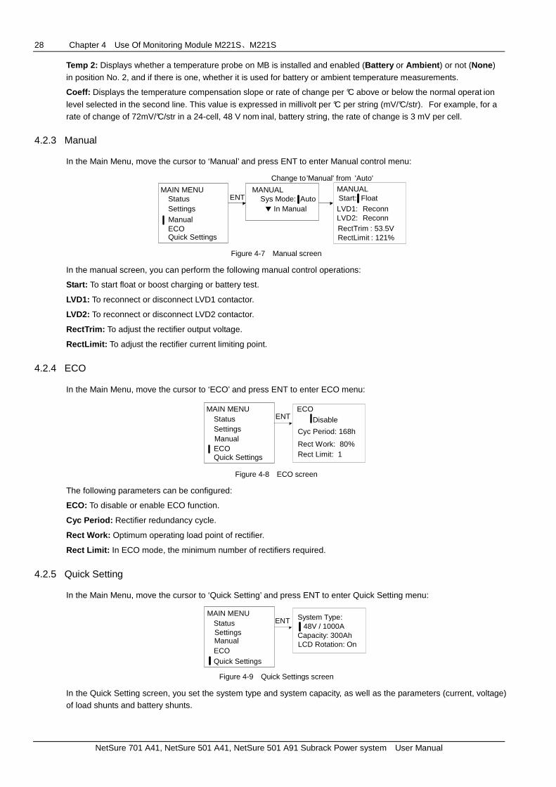
4.2.3 Manual
In the Main Menu, move the cursor to ‘Manual’ and press ENT to enter Manual control menu:
MAIN MENUStatusSettings
ECOManual
Quick Settings
ENTMANUALStart: FloatLVD1: ReconnLVD2: ReconnRectTrim : 53.5VRectLimit : 121%
MANUALSys Mode: Auto
In Manual
Change to 'Manual' from 'Auto'
Figure 4-7 Manual screen
In the manual screen, you can perform the following manual control operations:
Start: To start float or boost charging or battery test.
LVD1: To reconnect or disconnect LVD1 contactor.
LVD2: To reconnect or disconnect LVD2 contactor.
RectTrim: To adjust the rectifier output voltage.
RectLimit: To adjust the rectifier current limiting point.
4.2.4 ECO
In the Main Menu, move the cursor to ‘ECO’ and press ENT to enter ECO menu:
MAIN MENUStatusSettings
ECOManual
Quick Settings
ENTECO
Disable
Cyc Period: 168h
Rect Work: 80%Rect Limit: 1
Figure 4-8 ECO screen
The following parameters can be configured:
ECO: To disable or enable ECO function.
Cyc Period: Rectifier redundancy cycle.
Rect Work: Optimum operating load point of rectifier.
Rect Limit: In ECO mode, the minimum number of rectifiers required.
4.2.5 Quick Setting
In the Main Menu, move the cursor to ‘Quick Setting’ and press ENT to enter Quick Setting menu:
MAIN MENUStatusSettings
ECOManual
Quick Settings
ENT System Type:48V / 1000A
Capacity: 300AhLCD Rotation: On
Figure 4-9 Quick Settings screen
In the Quick Setting screen, you set the system type and system capacity, as well as the parameters (current, voltage) of load shunts and battery shunts.

Chapter 4 Use Of Monitoring Module M221S、M221S 29
NetSure 701 A41, NetSure 501 A41, NetSure 501 A91 Subrack Power system User Manual
4.2.6 Controller Setting
Table 3-7 summarizes all the settings of the controller.
Table 4-6 Controller Settings
Components Name Available Settings
Default setting Unit Low limit High limit
Alarm DI alarm mode High / low High /
Rectifier
HVSD point 56 59 59 V
Default voltage 48 58 53.5
Restart time upon over voltage 0 300 300 s
Soft-start time with load 8 128 8 s
Soft-start with load enabled Enabled/Disabled Disabled /
Startup upon AC over voltage Enabled/Disabled Disabled /
System ECO enabled Enabled/Disabled Disabled /
Sequencial start interval 0 10 0 s
Input current limiting 1 50 30
Rectifier slot setting enabled Enabled/Disabled Disabled /
Rectifier slot setting 1 30 1-1/2-2… /
Bat
tery
Basic battery parameters
Number of fuses 0 5 2
Nominal capacity 20 5000 600 Ah
Shunt Yes / No
Shunt current 1 2000 According to system type
A
Shunt voltage 1 500 25 mV
Temperature 1 None/Battery/Ambient Disabled /
Temperature 2 None/Battery/Ambient Disabled /
Battery charge parameters
Float charging voltage 42 58 53.5 V
Boost charging voltage 42 58 56.4 V
Charging current limiting 0.1 0.25 0.1 C10
Auto boost charging enabled Yes / No Yes /
Constant charging current 0.002 0.02 0.01 C10
Battery charge parameters
Constant current charging time 5 1440 180 Min
To boost charging current 0.04 0.08 0.06 C10
To boost charging capacity 10 99 80 %
Scheduled boost charging enabled Yes / No Yes /
Boost charging protection time 60 2880 1080 H
Scheduled boost charging cycle 2 8760 2400 h
Scheduled boost charging time 30 2880 720 Min
Battery test parameters
Battery test end time 5 1440 300 Min
Battery test end voltage 43.1 57.9 45.2 Min
Battery test end capacity 0 1 0.7 C10
Scheduled test enabled Yes No /
Constant current test enabled Yes / No No /
Constant battery test current 1 9999 9999 A
Short test enabled Yes / No No /
Short test alarm point 1 100 10 A
Short test cycle 24 8760 720 h
Short test time 1 60 5 min
Battery temp compensation coefficient
Temperature compensation central point
10 40 25 deg.C
Battery compensation coefficient 0 500 72 mv/deg.C
Battery over temperature point 10 100 50 deg.C
Battery high temperature point 10 100 50 deg.C
Battery low temperature point -40 10 0 deg.C
DC unit
Over voltage 1 40 60 58.5 V
Under voltage 1 40 60 45 V
Under voltage 2 40 60 45 V
High ambient temperature 10 100 40 deg.C
Low ambient temperature -40 10 -5 deg.C

30 Chapter 4 Use Of Monitoring Module M221S、M221S
NetSure 701 A41, NetSure 501 A41, NetSure 501 A91 Subrack Power system User Manual
Components Name Available Settings
Default setting Unit Low limit High limit
Load shunt Yes / No No /
LVD
LVD1 Enabled Disabled / Enabled Disabled /
LVD2 enabled Disabled /Enabled
Disabled /
LVD1 voltage 40 60 43.2 V
LVD2 voltage 40 60 43.2 V
AC unit
Over voltage alarm point 0 500(866) 280(485) V
Under voltage alarm point 0 500(866) 180(304) V
Phase failure alarm point 0 500(866) 80(255) %
Communication parameters
IP address 0-255 192.168.1.2 /
Subnet code 0-255 255.255.255.0 /
Default gateway 0-255 192.168.1.1 /
Local address 1 255 1 /
Port type RS232/Modem/ETH RS232 /
Baud rate 1200/2400/4800/9600 9600
Protocol YDN23/EEM/RSOC/SOCTPE YDN23 /
Alarm call-back enabled Yes / No No /
Call back times 0 10 3
Call back number 1
Call back number 2
Call back number 3
Controller parameters
Language English / Chinese English
Display time zone GMT+08:00
System date
System time
Restore default configurations Yes / No No
Set rotating screens Horizontal/Vertical Horizontal
System type
48V/set, 48V/1000A, 48V/500A, 48V/300A, 48V/100A, 24V/set, 24V/1000A, 24V/500A, 24V/300A and 24V/100A
48V/set
4.3 WEB Interface Operation
Through the WEB Interface, a remote user can:
View real-time operating information.
Send control commands.
Set programmable parameters.
Set which new alarms are displayed in a pop-up WEB window.
Download and upload configuration files.
4.3.1 Setting Up The Internet Explorer Web Browser
Procedure
Note
This procedure needs to be performed only when the controller is connected to an Internet and the User has set that the access to the Internet needs to be made through proxy. If the controller is connected Internet and the user computer is connected to the Internet, the user cannot disable the proxy, otherwise he will have no access to the controller.
1. Launch Internet Explorer.

Chapter 4 Use Of Monitoring Module M221S、M221S 31
NetSure 701 A41, NetSure 501 A41, NetSure 501 A91 Subrack Power system User Manual
2. Select Internet Options from the Tools menu. The ‘Internet Options’ window opens. In the ‘Internet Options’ window, select the Connections tab.
Figure 4-10 Internet options window
3. Click on the LAN Settings... button. The following window opens. In the LAN Settings window, uncheck the proxy box and click OK.
Figure 4-11 LAN settings window
4.3.2 Logging Into The Controller
Procedure
In Internet Explorer, enter the IP address programmed into the controller and press ENTER. The following WEB Interface window opens. Enter a valid User Name and Password, and then click OK. By default, there are two ‘User
Name’ and ‘Password’ combinations, one is ‘admin’ and ‘640275’, the other is ‘operator’ and ‘1’. The username of ‘admin’ has the highest authority and the username ‘operator’ has no authority for uploading and downloading configuration files.

32 Chapter 4 Use Of Monitoring Module M221S、M221S
NetSure 701 A41, NetSure 501 A41, NetSure 501 A91 Subrack Power system User Manual
Figure 4-12 Access to controller
4.3.3 Homepage Introduction
After entering a valid User Name and Password , and clicking OK; the homepage window opens.
The homepage window is divided into three areas: System Information, Parameter Settings and Control Functions, and Upload/Download Files.
Figure 4-13 Homepage window
System information
At the top of homepage, System Information is displayed, such as System Voltage, System Load, MA/CA Number, OA Number, Battery Mode, Site Name, HW Version, and SW Version.
Parameter and control function
You can set the following parameters and control functions:
Battery Temp Comp: To disable or enable the battery temperature compensation function.

Chapter 4 Use Of Monitoring Module M221S、M221S 33
NetSure 701 A41, NetSure 501 A41, NetSure 501 A91 Subrack Power system User Manual
Battery Test: To disable or enable the periodical battery test function. This setting has no effect on the short
test.
Current Limitation: To disable or enable the battery charging current limitation function.
Boost Charge: To disable or enable the periodical battery boost charging function. This setting has no effect on
auto boost charging.
LVD1 Level, LVD2 Level: To set the low voltage disconnection point.
Under Voltage Level 1, Under Voltage Level 2: To set the under voltage point.
System Volt: To set the system voltage.
Boost Volt: To set the battery boost charging voltage.
NMS1 IP, NMS2 IP: To set the IP address of SNMP
Remote1 IP, Remote2 IP: To set the IP address of EEM protocol.
TCP IP address: To set the IP address of TCP IP protocol.
Upload/download files
1. Procedure
1) To upload a configuration file, click the Upload button. The following window opens. Click the Save button.
Figure 4-14 Uploading the configuration file
2) The following window opens. Navigate to where you want the file to be saved. Click the Save button.
Figure 4-15 Save as window

34 Chapter 4 Use Of Monitoring Module M221S、M221S
NetSure 701 A41, NetSure 501 A41, NetSure 501 A91 Subrack Power system User Manual
After the upload is completed, the system will pop up a window to prompt the user that the upload is successful:
Figure 4-16 Upload successful
3) Users can also upload up to 80 active alarms or history alarms.
4) To download a file, click the Browse button. Navigate to and select the configuration file to be downloaded:
Figure 4-17 Selecting the configuration file

Chapter 4 Use Of Monitoring Module M221S、M221S 35
NetSure 701 A41, NetSure 501 A41, NetSure 501 A91 Subrack Power system User Manual
Then click Open :
Figure 4-18 Access to the homepage
Then click Download button, the system will pop up a window requiring you to confirm:
Figure 4-19 Confirmation window

36 Chapter 4 Use Of Monitoring Module M221S、M221S
NetSure 701 A41, NetSure 501 A41, NetSure 501 A91 Subrack Power system User Manual
Click OK, the system will prompt you that the download is successful:
Figure 4-20 Download successful
In the above screen, you can click ‘Back to the Homepage’ to return to the Homepage.
Administrator can click ‘Go to Firmware Download Mode’ to enter Bootloader download interface.
4.4 WEB Bootloader Interface Operation
Below is the web download webpage. In this webpage administrator can update the firmware. Please ensure that the file name of the firmware is M221S.bin.
Figure 4-21 WEB webpage

Chapter 4 Use Of Monitoring Module M221S、M221S 37
NetSure 701 A41, NetSure 501 A41, NetSure 501 A91 Subrack Power system User Manual
4.5 Serial Bootloader Interface Operation
Serial COM PORT can be used to download and upload files through the following procedure:
1. Connect Serial line to the computer and LCU+. Connect the DB9 terminal to computer, while connect the RJ45 terminal to the port assigned with ‘IOIO’ on LCU+.
2. Open the software of HyperTerminal on the computer, set the parameters according to the following method, here we use COM1, however, other COM PORT is optional dependent on your computer.
Figure 4-22 Choose the COM port
Figure 4-23 Set the parameters of COM port

38 Chapter 4 Use Of Monitoring Module M221S、M221S
NetSure 701 A41, NetSure 501 A41, NetSure 501 A91 Subrack Power system User Manual
Figure 4-24 Main menu of download/upload
Here we can see there are 4 options, choose ‘1’ to download the application program, choose ‘2’ to download the configuration data, choose ‘3’ to upload the data configuration file, choose ‘4’ to execute the application program. 1. Method of downloading the application program:
1) Press ‘1’ on the keyboard, enter the surface of download;
2) Choose Transfer->Send File… , select the .bin file you want to download;
Figure 4-25 Choose the file

Chapter 4 Use Of Monitoring Module M221S、M221S 39
NetSure 701 A41, NetSure 501 A41, NetSure 501 A91 Subrack Power system User Manual
Pay attention that the protocol is Ymodem
Figure 4-26 Choose Ymodem as protocol
3) Press ‘Send’, ‘.bin’ file is transmitted from computer to LCU+;
Figure 4-27 The process of downloading file
4) After the file downloading is completed successfully, the following interface pops up:
Figure 4-28 Downloading file successfully
2. Method of downloading the configuration data: Similar to the download of application program, will not be introduced here;
3. Method of uploading the data configuration file:
1) Press ‘3’ on the keyboard, enter the interface of uploading files:
Figure 4-29 Uploading the file
2) Choose Transfer->Receive File… to select the position in which you save the file

40 Chapter 4 Use Of Monitoring Module M221S、M221S
NetSure 701 A41, NetSure 501 A41, NetSure 501 A91 Subrack Power system User Manual
Figure 4-30 Select the position in which you save the file
Pay attention that the protocol is Ymodem.
Figure 4-31 Choose Ymodem as protocol
3) Press Receive , the file is transmitted from LCU+ to computer.
Figure 4-32 The process of uploading file
4) After the file downloading is completed successfully, the following interface pops up.
Figure 4-33 Uploading file successfully
You can also press "4" on the keyboard to execute the application.

Chapter 5 Use Of Monitoring Module M820B 41
NetSure 701 A41, NetSure 501 A41, NetSure 501 A91 Subrack Power system User Manual
Chapter 5 Use Of Monitoring Module M820B
This chapter introduces the front panel and functional keys briefly, and expounds screen contents, access method, system controlling, information querying, parameter setting, access M820B through web and NMS, and parameter setting guidance.
5.1 Operation Panel
M820B Panel is illustrated in Figure 5-1:
Figure 5-1 M820B panel
Functions of LED indicators are illustrated in Table 5-1.
Table 5-1 Functions of LED indicators
LED Normal status Abnormal status Cause
Run Indicator (green) On Off No power supply
Protection Indicator (yellow) Off On The power system has at least an observation alarm
Alarm Indicator (red) Off On The power system has at least a major alarm or critical alarm
The M820B controller has two kinds of LCD: One is a 128 × 64 dot-matrix LCD unit that can display 4 rows of text and the other is 128 × 128 dot-matrix LCD that can display 8 rows of text. It has 4 functional keys. Its interface is easy-to-use and supports multi-language display. The panel of the controller is easy-to-remove. The functions of these 4 keys are shown in Table 5-2.
Table 5-2 Functions of M820B keys
Keys Name of Keys Functions
ESC Return Key Press this key to back to previous menu or cancel a setting of a parameter .
Press ESC and ENT together to reset ACU+
ENT Enter Key Press this key to go to next menu or highlight editable area for parameter setting, validate the change made to a parameter setting.
Up
Press or to scroll through the menus.
These two arrow keys can be used to change the value of a parameter: Press or to move the cursor to the parameter to be changed and change the value of a parameter Down
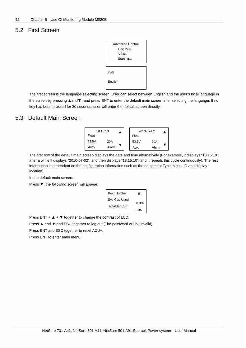
42 Chapter 5 Use Of Monitoring Module M820B
NetSure 701 A41, NetSure 501 A41, NetSure 501 A91 Subrack Power system User Manual
5.2 First Screen
Advanced Control
Unit PlusV2.01
Starting...
英语
English
The first screen is the language-selecting screen. User can select between English and the user’s local language in
the screen by pressing and, and press ENT to enter the default main screen after selecting the language. If no
key has been pressed for 30 seconds, user will enter the default screen directly.
5.3 Default Main Screen
18:15:10Float
53.5V
Auto Alarm
20A
2010-07-02Float
53.5V
Auto Alarm
20A
The first row of the default main screen displays the date and time alternatively (For example, it displays “18:15:10”, after a while it displays “2010-07-02”, and then displays “18:15:10”, and it repeats this cycle continuously). The rest information is dependent on the configuration information such as the equipment Type, signal ID and display location).
In the default main screen:
Press , the following screen will appear.
Rect Number
TotalBattCurr
5
Sys Cap Used0.0%
10A
Press ENT + + together to change the contrast of LCD.
Press and and ESC together to log out (The password will be invalid).
Press ENT and ESC together to reset ACU+.
Press ENT to enter main menu.

Chapter 5 Use Of Monitoring Module M820B 43
NetSure 701 A41, NetSure 501 A41, NetSure 501 A91 Subrack Power system User Manual
5.4 Overall Menu Structure
The overall menu structure is shown in the following figure.
Time/DateFloat##.#V ###AAuto Alarm
Rect Num:SysCap Used:
TotalBattCurr:##A
MAIN MENUStatusSettingsEnergy SavingManual
Quick Settings
STATUSActive AlarmPower SystemRectifierBattery
SETTINGSAlarm SettingPower SystemRectifier
##
##.#%ACDC
History AlarmSite Inventory
Batt2
BATTERYBatt1
SMDU Batt1
Battery
DCLVDACCommunicationController
ECO Mode
MANUALMan / Auto SetPower SystemRectifierBattery GroupLVD
Quick SettingsAuto / Manual
RECTIFIERRect GroupRect1Rect2
CurrLmt: ##.#%ALL DC: On/Off
AC ControlON
DC ControlOFF
RECTIFIER
Position
High Voltage Limit: ##
BATTERYBasicCharge DataTest Data
LVDAC Fail Enb
SMDU LVD1
Enabled
Dev Name
Serial No.
031000500115
SW Rev:2.01
M820D
NGC-HF Level1 Level2
BatteryFuseUnit
ECO Mode SetFC / BC VoltageFC / BC ChangeTemp CompensWork Mode Set
Level3
SMDU Batt2EIB Batt1......
......
Rect Group
......
......
LVD Temp EnbLVD 1LVD 2
ECO ModeEnabled
EngySave Point
Fluct Range
Best Point0.0%
45%
10%Cyc Period
168 hourRect Drying Tim
120 minSwitchOff Delay
5 min
......
......
Low Voltage Limit: ##......
Rect 1 ###Rect 1 ###Rect 2 ###Rect 2 ###......
Figure 5-2 ACU+ Overall Menu Structure
5.5 Main Menu
09:20:20
Float53.4V 20AAuto Alarm
ENT MAIN MENUStatus
Manual
SettingsEnergy Saving
Quick Settings
ESCDev Name
Serial No.
031000500115
SW Rev: 2.01
M820D
Figure 5-3 Main Menu
Main Menu includes running information, settings, energy saving, manual control and quick settings.

44 Chapter 5 Use Of Monitoring Module M820B
NetSure 701 A41, NetSure 501 A41, NetSure 501 A91 Subrack Power system User Manual
5.6 Status
In the main menu, move cursor to “Status”, press ENT to show the status menu as shown in the following figure.
ENTMAIN MENUStatusSettingsEnergy SavingManualQuick Settings
StatusActive AlarmPower SystemRectifierBatteryDCACEIBSMDU UnitHistory AlarmSite Inventory
Figure 5-4 Status Menu
In the screen of MAINMENU, when cursor is at “Status”, press “ENT” to go to the status screen, and when cursor is at “Active Alarm”, press “ENT” to show the following screen to check Active Alarm information.
StatusActive AlarmPower SystemRectifierBatteryDCACEIBSMDU UnitHistory AlarmSite Inventory
Active AlarmObservation: 1Major: 0Critical: 0
ENT
Figure 5-5 Active Alarm Information
The Active Alarm screen shows the information of the alarms, and the number of the alarms in different alarm levels (Observation, Major and Critical) are displayed, and alarm start time are displayed in the screen. If you want to see the information of other unit, move cursor to this unit and just press “ENT”. Using the same method, you can browse all the information listed in the following table.
Table 5-3 Device Information
No. Status Information Description
Active Alarm
1 Observation: Number of observation alarms
2 Major: Number of major alarms
3 Critical: Number of critical alarms
Power System
1 System Voltage System output voltage
2 System Load System output current
3 Mtn Time Run
4 Alarm Status Whether or not the system is in alarming status
5 Power Split Whether this system is master or slave in a power split system
6 SPD Surge protection device
Rectifier
Rect 1 (001)
1 DC Voltage Rectifier output voltage
2 DC Current Rectifier output current
3 Current Limit Current limit value
4 Temperature Rectifier internal temperature
5 DC Status Whether the DC is on or off
6 Derated by AC Rectifier output power is derated according to input voltage
7 Derated by Temp Rectifier output power is derated according to temperature
8 Walk-in Func Rectifier soft start function
9 Rect Position

Chapter 5 Use Of Monitoring Module M820B 45
NetSure 701 A41, NetSure 501 A41, NetSure 501 A91 Subrack Power system User Manual
No. Status Information Description
10 Rect Phase Whether the rectifier is on Phase A, or Phase B or Phase C?
11 Rectifier SN Rectifier series number
12 Running Time Rectifier operating time
13 AC Voltage Rectifier input AC voltage
Rect 2 (002): The information of Rect 2 (002) is similar to Rect 1 (001), so is the information of other rectifiers in the system.
Battery
Battery 1
1 Batt Current Battery current
2 Batt Voltage Battery voltage
3 Batt Cap (Ah) Battery capacity and the unit is Ah
4 Batt Cap (%) Battery capacity and the unit is %
Battery 2, SMDU/Batt3 and SMDU/Batt4: The information of these batteries is similar to that of Battery 1.
DC
1 DC Voltage DC output voltage
AC
Rect1 AC
1 Phase A Voltage The line-to-neutral voltage of Phase A of rectifier 1
2 Phase B Voltage The line-to-neutral voltage of Phase B of rectifier 1
3 Phase C Voltage The line-to-neutral voltage of Phase C of rectifier 1
OB AC Unit: The information of OB AC Unit is similar to that of Rect AC.
EIB
1 Bad Battery Blo Bad battery block
2 Load 1 Current Current of load 1
3 Load 2 Current Current of load 2
4 Load 3 Current Current of load 3
5 Voltage 1 Voltage of load 1
6 Voltage 2 Voltage of load 2
7 Voltage 3 Voltage of load 3
History Alarm
1 Observation: Number of observation alarms
2 Major: Number of major alarms
3 Critical: Number of critical alarms
Site Inventory
Rectifier 1
1 Device Name Name of the device
2 Product Ver Product version number
3 SW Version Software version number
4 Serial Number Serial number of the device
The screens give user the information about what devices are available and the device information. The information of SM DU,
Controller and IB1 board are similar to the rectifier information that includes the device name, product version, software version
and serial number

46 Chapter 5 Use Of Monitoring Module M820B
NetSure 701 A41, NetSure 501 A41, NetSure 501 A91 Subrack Power system User Manual
For some devices, there are more than one menu levels, and you need to press ENT more than one time to browse its information. Take “Rectifier” for example.
StatusActive AlarmPower SystemRectifierBatteryDCACEIB
SMDU UnitHistory AlarmSite Inventory
ENT RectifierRect 1 (001)Rect 2 (002)
ENT DC Voltage53.8 V
DC Current8.5 A
Curr Limit60 %
Temperature30 deg C
DC StatusOff
Derated by ACNormal
Derated by TempNormal
Walk -in FuncDisabled
Rect Position1
Rect PhaseA
Rectifier SN010700213
Running Time200 h
AC Voltage224 V
Figure 5-6 Rectifier Information
5.7 Manual
ENTMAIN MENU
StatusSettingsEnergy Saving
Quick Settings
Manual
Man / Auto SetPower SystemRectifierBatt GroupLVD
Manual
Select User
admin
Enter Password*
ENT
Figure 5-7 Manual Operations
In the Main Menu, move the cursor to the position of “Manual”, and press ENT, the system will require you to select user first and then enter password. To enter the password: Move the cursor to the character “*”. Press ENT to highlight the character “*” and then press and to change value of this character. After entering the password, press ENT to show the “Manual” operation menus.
ENTManualMan / Auto SetPower SystemRectifier
Batt GroupLVD
Auto/Man StateAuto
Figure 5-8 Manual / Auto Control Status
In the screen as shown in Figure 3-8, you can set the system from “Auto” control to “Manual” control. Setting method: When the cursor is beside the “Auto”, press ENT to highlight the characters of “Auto”, and then press and to change the “Auto” to “Manual”. After the system is set to “Manual” control, you can set the system manually.

Chapter 5 Use Of Monitoring Module M820B 47
NetSure 701 A41, NetSure 501 A41, NetSure 501 A91 Subrack Power system User Manual
Move the cursor to “Power System”, and press ENT, following screen will show up.
ENTManualMan / Auto SetPower System
RectifierBatt Group
LVD
Clr Run TimeYes
Figure 5-9 Set the Power System Manually
If you set “Clr Run Time” to “Yes”, the system running time record will be cleared.
Move the cursor to “Rectifier”, and press ENT, following screen will show up.
ENTManualMan / Auto SetPower SystemRectifierBatt GroupLVD
RectifierAll Rect CtrlRect1(001)Rect2(002)
ENT RectTrim54.0 V
Current Limit60 %
DC On / Off CtrlSwitch on All
LEDs ControlStop Twinkle
Fan Speed CtrlAuto Speed
Clear Rect LoseClear
Reset OscillClear
Confirm Posi/PHYes
Clear Comm FailYes
Figure 5-10 Set the Rectifier Manually
Move the cursor to “Batt Group”, and press ENT, following screen will show up.
ENTManualMan / Auto Set
Power SystemRectifierBatt GroupLVD
BC / FC ControlFloat Charge
BT Start/StopStop
Reset CapacityYes
Clear BadBatt AYes
Clear Abcur AlmYes
Clear Imcur AlmYes
Figure 5-11 Set Battery Group Manually
Move the cursor to “LVD”, and press ENT, following screen will show up.
ENTManualMan / Auto SetPower System
RectifierBatt GroupLVD
LVD1 ControlConnected
LVD2 Control
Connected
Figure 5-12 Set LVD Manually
5.7.1 Settings
In the submenu of “Settings”, you can set the parameters of alarm, power system, rectifier, battery, DC distribution, LVD, AC, communication and controller.

48 Chapter 5 Use Of Monitoring Module M820B
NetSure 701 A41, NetSure 501 A41, NetSure 501 A91 Subrack Power system User Manual
Alarm Setting
Move cursor to “Alarm Setting”, press ENT to show the following screen.
ENTMAIN MENU
Status
Manual
SettingsEnergy Saving
Quick Settings
SettingsAlarm SettingPower SystemRectifier
Battery
DCLVDACCommunicationController
Alarm SettingsAlarm SeverityAlarm RelayAlarm Param
ENTSelect User
admin
Enter Password
*
ENT
BatteryFuseUnit
Figure 5-13 Alarm Setting
Alarm severity setting
Move the cursor to the “Alarm Severity”, press ENT to pop up the following screen.
Alarm Settings
Alarm Relay
Alarm Param
ENTAlarm Severity
Power SystemRect GroupRectifierBattery GroupBattery
OBBattery FusSMDU Batt FusDCDC Fuse Unit
SMDU DC Fuse
LVDSMDU LVD
ENTSelf Detect Fail
ObservationCAN Comm Fail
CriticalAlarm Blocked
Observation…….
Alarm Severity
.SMDU BatteryEIB BatterySM BattLdu Battery
LargeDU LVD......
Figure 5-14 Alarm Severity Setting of Power System
In this menu, you can set the severity levels of the alarms of power system, rectifier group, rectifier, battery group, battery, SM DU battery fuse, OB battery fuse, DC distribution, DC fuse, LVD, AC, IB, EIB and converter. Move cursor to “Power System”, and press ENT, the power system alarm severity setting screen will pop up.
In the screen as shown in Figure 3-14, the alarms of power system are displayed, such as “Self Detect Fail”, “CAN Comm Fail”, “Alarm Blocked”, etc. The default alarm severities of the alarm are also displayed, such as “Critical” and “Observation”. Method of change alarm severity: With the alarm of “Self Detect Fail” as an example, move the cursor to the alarm severity of “Observation”, press ENT to highlight the “Observation”, and then press and to change the severity from “Observation” to “Critical” or “Major” or “No Alarm”. You can also change the severity of other alarms such as “CAN Comm Fail” and “Alarm Blocked” using the same method. In Figure 3-20, move the cursor to “Rect Group”, you can set the severity levels of the alarms of rectifier group. The ACU+ has 4 alarm severity levels as shown in the following table.
Table 5-4 Characteristics of 4 alarm categories
Alarm levels
Red alarm indicator
of controller and
system
Yellow alarm indicator
of controller and
system
Alarm
buzzer
Alarm call
back Remark
CA (critical alarm) On On Yes Alarm call back is enabled
MA (major alarm) On On Yes Alarm call back is enabled
OA (observation alarm) On Off No
No alarm Off Off Off No

Chapter 5 Use Of Monitoring Module M820B 49
NetSure 701 A41, NetSure 501 A41, NetSure 501 A91 Subrack Power system User Manual
The alarm list and the default alarm severity levels of the ACU+ is shown in the following table:
Table 5-5 List of Alarms and Alarm Severity Levels of ACU+
No. Alarm Name Alarm Description Default Alarm
Severity
Alarms of power system
1 Self Detect Fail System self detection failure Observation
2 CAN Comm Fail CAN bus communication failure. Critical
3 Alarm Blocked Alarm is blocked Observation
4 Maintenance Alrm Maintenance alarm No Alarm
5 Config Error 1 Configuration error 1 Observation
6 Config Error 2 Configuration error 2 Observation
7 Imbalance Curr Current sharing imbalance Critical
8 Over Load DC power system overload Observation
9 SPD Surge protection device tripped Critical
10 EStop/EShutdown Emergency stop or emergency shutdown Critical
11 Temp 1 Not Used Temp 1 sensor is not used Observation
12 Temp 2 Not Used Observation
13 Temp 3 Not Used Observation
14 Temp 4 Not Used Observation
15 Temp 5 Not Used Observation
16 Temp 6 Not Used Observation
17 Temp 7 Not Used Observation
18 T1 Sensor Fault Temperature sensor 1 failure conditon Observation
19 T2 Sensor Fault Temperature sensor 2 has fault Observation
20 T3 Sensor Fault Temperature sensor 3 has fault Observation
21 T4 Sensor Fault Temperature sensor 4 has fault Observation
22 T5 Sensor Fault Temperature sensor 5 has fault Observation
23 T6 Sensor Fault Temperature sensor 6 has fault Observation
24 T7 Sensor Fault Temperature sensor 7 has fault Observation
25 Temp1 High2 Temperature 1 exceeds high temperature threshold 2 Major
26 Temp2 High2 Temperature 2 exceeds high temperature threshold 2 Major
27 …….. …….. Major
31 Temp7 High2 Temperature 7 exceeds high temperature threshold 2 Major
32 Temp1 High1 Temperature 1 exceeds high temperature threshold 1 Major
33 Temp2 High1 Temperature 2 exceeds high temperature threshold 1 Major
34 …….. …….. Major
38 Temp7 High1 Temperature 7 exceeds high temperature threshold 1 Major
39 Temp1 Low Temperature 1 low Observation
40 Temp2 Low Temperature 2 low Observation
41 …….. …….. Observation
45 Temp7 Low Temperature 7 low Observation
46 DHCP Failure DHCP function enabled, but cannot acquire IP address Observation
Alarms of Rect Group
1 Multi-rect Fail More than one rectifier failure detected Critical
2 Rectifier Lost Rectifier cannot be detected by the controller Critical
3 Redund Active Rectifier redundancy is enabled Observation
4 Rect No Resp Rectifier communication failure Major
5 Redund Oscill Indicates rectifier redundancy condition has changed
status more than 5 times due to load change Observation
Alarms of Rectifier
1 AC Failure Rectifier AC power fails Major
2 Rect Temp High Rectifier temperature high Major
3 Rect Fault Rectifier fault Major
4 Over Voltage Rectifier over voltage Major
5 Rect Protected Rectifier is protected Major
6 Fan Failure Rectifier fan fails Major
7 Current Limit Rectifier is in current limiting status Major
8 Comm Fail Rectifier communication fails Major
9 Derated Rectifier output power is derated Observation

50 Chapter 5 Use Of Monitoring Module M820B
NetSure 701 A41, NetSure 501 A41, NetSure 501 A91 Subrack Power system User Manual
No. Alarm Name Alarm Description Default Alarm
Severity
10 SharingCurr Alm Rectifier has current sharing alarm Observation
11 U-Volt Protect Under voltage protection Major
Alarms of Batt Group
1 Short Test Battery short time test Observation
2 Boost For Test Boost charge test Observation
3 Manual Test Manual battery discharge test Observation
4 Plan Test Planned battery test Observation
5 AC Fail Test Switch off AC power to perform the battery discharging
test Observation
6 Manual Boost Manually start the boost charging Observation
7 Auto BC Automatic boost charging Observation
8 Cyclic Boost Cyclic boost charging Observation
9 Master Boost In slave mode, the slave unit starts boost charging with
the master unit Observation
10 Master Test In slave mode, the slave unit starts the test with the
master unit Observation
11 Dis Curr Im Rectifier distribution current alarm Observation
12 Abnorm Batt Curr Battery current is abnormal Observation
13 Temp Comp Activ Temperature compensation is started Observation
14 Batt Curr Lmt Battery current limit Observation
15 Bad Battery Battery block fails Observation
16 Battery Dischar Battery discharging Observation
Alarms of Battery
1 Exceed Curr Lmt Current limit point is exceeded Observation
2 Over Current Battery over current Observation
3 Low Capacity Battery low capacity Observation
Alarms of SMDU Battery
1 Exceed Curr Lmt Current limit point is exceeded Observation
2 Over Current Battery over current Observation
3 Low Capacity Battery low capacity Observation
Alarms of EIB Battery
1 Exceed Curr Lmt Current limit point is exceeded Observation
2 Over Current Battery over current Observation
3 Low Capacity Battery low capacity Observation
Alarms of SM Batt
1 Over Curr Lmt Current limit point is exceeded Observation
2 Ov Batt Current Battery over current Observation
3 Battery Leakage Battery has leakage Observation
4 Low Acid Level Battery electrolytic level is low Observation
5 Batt disconnec Battery is disconnected Observation
6 Batt high temp Battery temperature is high Observation
7 Batt low temp Battery temperature is low Observation
8 Cell volt diff Cell voltage is diffierent Observation
9 SM unit fail SM Unit failure Observation
10 T Sensor Fault Temperature sensor fails Observation
11 Low Capacity Battery low capacity Observation
12 Battery No Resp Battery has no response Observation
13 Battery Temp no No battery temperature Observation
Alarms of Ldu Battery
1 Exceed Curr Lmt Current limit point is exceeded Observation
2 Low Capacity Battery low capacity Observation
3 Fuse Failure Battery fuse fails Critical
4 Over Volt Battery over voltage Observation
5 Under Volt Battery under voltage Observation
6 Over Curr Battery over current Observation
7 No Response Battery has no response Observation
Alarms of OBBattery Fus
1 Fuse1 Alarm Battery fuse 1 alarm Critical

Chapter 5 Use Of Monitoring Module M820B 51
NetSure 701 A41, NetSure 501 A41, NetSure 501 A91 Subrack Power system User Manual
No. Alarm Name Alarm Description Default Alarm
Severity
2 Fuse2 Alarm Battery fuse 2 alarm Critical
3 Fuse3 Alarm Battery fuse 3 alarm Critical
4 Fuse4 Alarm Battery fuse 4 alarm Critical
Alarms of SMDUBattery Fus
1 Batt Fuse 1 Alm Battery fuse 1 alarm Critical
2 Batt Fuse 2 Alm Battery fuse 2 alarm Critical
3 Batt Fuse 3 Alm Battery fuse 3 alarm Critical
4 Batt Fuse 4 Alm Battery fuse 4 alarm Critical
Alarms of DC
1 Over Voltage1 DC over voltage 1 Critical
2 Over Voltage2 DC over voltage 2 Critical
3 Under Voltage1 DC under voltage 1 Critical
4 Under Voltage2 DC under voltage 2 Critical
Alarms of DC Fuse Unit
1 Fuse1 Alarm Fuse 1 alarm Critical
2 Fuse2 Alarm Fuse 2 alarm Critical
3 …….. …….. Critical
10 Fuse10 Alarm Fuse 10 alarm Critical
Alarms of SMDU DC Fuse
1 DC Fuse1 Alarm Critical
2 DC Fuse2 Alarm Critical
3 …….. Critical
16 DC Fuse16 Alarm Critical
Alarms of LVD
1 LVD1 Disconnect LVD1 contactor disconnected Critical
2 LVD2 Disconnect LVD2 contactor disconnected Critical
3 LVD1 Failure LVD1 contactor fails Critical
4 LVD2 Failure LVD2 contactor fails Critical
Alarms of SMDU LVD
1 LVD1 Disconnect LVD1 contactor disconnected Critical
2 LVD2 Disconnect LVD2 contactor disconnected Critical
3 LVD1 Failure LVD1 contactor fails Critical
4 LVD2 Failure LVD2 contactor fails Critical
Alarms of LargDU LVD
1 LVD1 Disconnect LVD1 contactor disconnected Critical
2 LVD2 Disconnect LVD2 contactor disconnected Critical
Alarms of AC
1 L-AB OverVolt1 Line A-to-Line B over voltage 1 Observation
2 L-AB OverVolt2 Line A-to-Line B over voltage 2 Observation
3 L-AB UnderVolt1 Line A-to-Line B under voltage 1 Observation
4 L-AB UnderVolt2 Line A-to-Line B under voltage 2 Observation
5 L-BC OverVolt1 Line B-to-Line C over voltage 1 Observation
6 L-BC OverVolt2 Line B-to-Line C over voltage 2 Observation
7 L-BC UnderVolt1 Line B-to-Line C under voltage 1 Observation
8 L-BC UnderVolt2 Line B-to-Line C under voltage 2 Observation
9 L-CA OverVolt1 Line C-to-Line A over voltage 1 Observation
10 L-CA OverVolt2 Line C-to-Line A over voltage 2 Observation
11 L-CA UnderVolt1 Line C-to-Line A under voltage 1 Observation
12 L-CA UnderVolt2 Line C-to-Line A under voltage 2 Observation
13 PH-A OverVolt1 Phase A over voltage 1 Observation
14 PH-A OverVolt2 Phase A over voltage 2 Observation
15 PH-A UnderVolt1 Phase A under voltage 1 Observation
16 PH-A UnderVolt2 Phase A under voltage 2 Observation
17 PH-B OverVolt1 Phase B over voltage 1 Observation
18 PH-B OverVolt2 Phase B over voltage 2 Observation
19 PH-B UnderVolt1 Phase B under voltage 1 Observation
20 PH-B UnderVolt2 Phase B under voltage 2 Observation
21 PH-C OverVolt1 Phase C over voltage 1 Observation

52 Chapter 5 Use Of Monitoring Module M820B
NetSure 701 A41, NetSure 501 A41, NetSure 501 A91 Subrack Power system User Manual
No. Alarm Name Alarm Description Default Alarm
Severity
22 PH-C OverVolt2 Phase C over voltage 2 Observation
23 PH-C UnderVolt1 Phase C under voltage 1 Observation
24 PH-C UnderVolt2 Phase C under voltage 2 Observation
25 Mains Failure AC mains power fails Critical
Alarms of OB AC Unit
1 PH-A OverVolt1 Phase A over voltage 1 Observation
2 PH-A OverVolt2 Phase A over voltage 2 Observation
3 PH-A UnderVolt1 Phase A under voltage 1 Observation
4 PH-A UnderVolt2 Phase A under voltage 2 Observation
5 PH-B OverVolt1 Phase B over voltage 1 Observation
6 PH-B OverVolt2 Phase B over voltage 2 Observation
7 PH-B UnderVolt1 Phase B under voltage 1 Observation
8 PH-B UnderVolt2 Phase B under voltage 2 Observation
9 PH-C OverVolt1 Phase C over voltage 1 Observation
10 PH-C OverVolt2 Phase C over voltage 2 Observation
11 PH-C UnderVolt1 Phase C under voltage 1 Observation
12 PH-C UnderVolt2 Phase C under voltage 2 Observation
13 Mains Failure AC mains power fails Critical
14 SevereMainsFail AC mains voltage is too low Critical
Alarms of SMAC
1 Supervision Fa Supervision failure Observation
2 High L-Volt AB Line A-Line B voltage high Observation
3 Vhigh L-Volt AB Line A-Line B voltage very high Major
4 Low L-Volt AB Line A-Line B voltage low Observation
5 VLow L-Volt AB Line A-Line B voltage very low Major
6 High L-Volt BC Line B-Line C voltage high Observation
7 VHigh L-Volt BC Line B-Line C voltage very high Major
8 Low L-Volt BC Line B-Line C voltage low Observation
9 VLow L-Volt BC Line B-Line C voltage very low Major
10 High L-Volt CA Line C-Line A voltage high Observation
11 Vhigh L-Volt CA Line C-Line A voltage very high Major
12 Low L-Volt CA Line C-Line A voltage low Observation
13 VLow L-Volt CA Line C-Line A voltage very low Major
14 High Ph-Volt A Phase A voltage high Observation
15 VHigh Ph-Volt A Phase A voltage very high Major
16 Low Ph-Volt A Phase A voltage low Observation
17 VLow Ph-Volt A Phase A voltage very low Major
18 High Ph-Volt B Phase B voltage high Observation
19 VHigh Ph-Volt B Phase B voltage very high Major
20 Low Ph-Volt B Phase B voltage low Observation
21 VLow Ph-Volt B Phase B voltage very low Major
22 High Ph-Volt C Phase C voltage high Observation
23 VHigh Ph-Volt C Phase C voltage very high Major
24 Low Ph-Volt C Phase C voltage low Observation
25 VLow Ph-Volt C Phase C voltage very low Major
26 Mains Failure Mains power outage Critical
27 Severe Mains Fai Severe mains power outage Critical
28 High Frequency AC power frequency is high Major
29 Low Frequency AC power frequency is low Major
30 High Temp High temperature Observation
31 Low Temperature Low temperature Observation
32 A High Current Phase A high current Observation
33 B High Current Phase B high current Observation
34 C High Current Phase C high current Observation
Alarms of IB
1 IB Failure Critical
2 DI1 Alarm Digital input 1 alarm Critical
3 DI2 Alarm Digital input 2 alarm Critical

Chapter 5 Use Of Monitoring Module M820B 53
NetSure 701 A41, NetSure 501 A41, NetSure 501 A91 Subrack Power system User Manual
No. Alarm Name Alarm Description Default Alarm
Severity
4 …….. …….. Critical
9 DI8 Alarm Digital input 8 alarm Critical
Alarms of EIB
1 EIB Failure EIB board fails Critical
2 Bad Batt Block Battery block fails Observation
Alarms of SMDU Unit
1 Under Voltage Observation
2 Over Voltage Observation
3 Comm Interrupt Rectifier communication failure Major
Alarms of Converter
1 Converter Fail Major
Alarms of SMIO 1
1 SMIO Fail SM IO fails Observation
Alarms of SMIO Unit 2—SMIO Unit 8
1 Hi-AI 1 Alarm Analog input 1 high alarm Observation
2 Low-AI 1 Alarm Analog input 1 low alarm Observation
3 Hi-AI 2 Alarm Analog input 1 high alarm Observation
4 Low-AI 2 Alarm Analog input 1 low alarm Observation
5 Hi-AI 3 Alarm Analog input 1 high alarm Observation
6 Low-AI 3 Alarm Analog input 1 low alarm Observation
7 Hi-AI 4 Alarm Analog input 1 high alarm Observation
8 Low-AI 4 Alarm Analog input 1 low alarm Observation
9 Hi-AI 5 Alarm Analog input 1 high alarm Observation
10 Low-AI 5 Alarm Analog input 1 low alarm Observation
11 Hi-Freq IN Alm High frequency input alarm Observation
12 Low-Freq IN Alm Low frequency input alarm Observation
13 SMIO Fail SM IO failure Observation
Alarms of ACD Group
1 Mains Failure Mains power outage Major
Alarms of AC Distri
1 Mains 1 Fail Mains 1 failure Major
2 Mains 2 Fail Mains 2 failure Major
3 Mains 3 Fail Mains 3 failure Major
4 M1 Uab/a Fail Mains 1 Uab/a failure Major
5 M1 Ubc/b Fail Mains 1 Ubc/b failure Major
6 M1 Uca/c Fail Mains 1 Uca/c failure Major
7 M2 Uab/a Fail Mains 2 Uab/a failure Major
8 M2 Ubc/b Fail Mains 2 Ubc/b failure Major
9 M2 Uca/c Fail Mains 2 Uca/c failure Major
10 M3 Uab/a Fail Mains 3 Uab/a failure Major
11 M3 Ubc/b Fail Mains 3 Ubc/b failure Major
12 M3 Uca/c Fail Mains 3 Uca/c failure Major
13 Over Frequency Major
14 Under Frequency Major
15 M1 Uab/a OverV M1 Uab/a Over Voltage Major
16 M1 Ubc/b OverV M1 Ubc/b Over Voltage Major
17 M1 Uca/c OverV M1 Uca/c Over Voltage Major
18 M2 Uab/a OverV M2 Uab/a Over Voltage Major
19 M2 Ubc/b OverV M2 Ubc/b Over Voltage Major
20 M2 Uca/c OverV M2 Uca/c Over Voltage Major
21 M3 Uab/a OverV M3 Uab/a Over Voltage Major
22 M3 Ubc/b OverV M3 Ubc/b Over Voltage Major
23 M3 Uca/c OverV M3 Uca/c Over Voltage Major
24 M1 Uab/a UnderV M1 Uab/a Under Voltage Major
25 M1 Ubc/b UnderV M1 Ubc/b Under Voltage Major
26 M1 Uca/c UnderV M1 Uca/c Under Voltage Major
27 M2 Uab/a UnderV M2 Uab/a Under Voltage Major
28 M2 Ubc/b UnderV M2 Ubc/b Under Voltage Major

54 Chapter 5 Use Of Monitoring Module M820B
NetSure 701 A41, NetSure 501 A41, NetSure 501 A91 Subrack Power system User Manual
No. Alarm Name Alarm Description Default Alarm
Severity
29 M2 Uca/c UnderV M2 Uca/c Under Voltage Major
30 M3 Uab/a UnderV M3 Uab/a Under Voltage Major
31 M3 Ubc/b UnderV M3 Ubc/b Under Voltage Major
32 M3 Uca/c UnderV M3 Uca/c Under Voltage Major
33 In-MCCB Trip Input MCCB trips Critical
34 Out-MCCB Trip Output MCCB trips Critical
35 SPD Trip SPD trips Critical
36 No Response No response Critical
Alarms of DC Distri
1 DC Over VOlt DC over voltage Critical
2 DC Under Volt DC under voltage Critical
3 Output1 Discon Output 1 disconnection Critical
.
.
.
.
.
.
.
.
.
.
.
.
66 Output 64 Discon Output 64 disconnection Critical
67 No Response No response Critical
68 T1 Over Temp T1 over temperature Critical
69 T2 Over Temp T2 over temperature Critical
70 T3 Over Temp T3 over temperature Critical
71 T1 Under Temp T1 Under temperature Critical
72 T2 Under Temp T2 Under temperature Critical
73 T3 Under Temp T3 Under temperature Critical
74 T1 sensor fail Temperature 1 sensor failure Observation
75 T2 sensor fail Temperature 2 sensor failure Observation
76 T3 sensor fail Temperature 3 sensor failure Observation
Alarms of Diesel Group
1 Diesel Test Observation
2 Test Failure Diesel test fails Major
3
Alarms of Diesel Genrat
1 Low DC Voltage DC voltage is low Major
2 Supervision Fai Supervision Failure Observation
3 Generator Fail Generator failure Critical
4 Genrtor Cnected Generator is connected Observation
5 Low Fuel Level Fuel level is low Major
6 High Water Temp Water temperature is high Major
7 Low Oil Press Oil pressure is low Major
Alarms of RectifierGrou
1 Rects No Resp Rectifiers have no response Major
2 Rectifier Lost Rectifier is lost Critical
3 Comm failure Rectifier communication failure Critical
4 Mains Failure Mains power outage Critical
Alarms of Group2Rectifi
1 AC Failure AC input power failure Major
2 Rect Temp High Rectifier temperature is high Major
3 Rect Fault Rectifier has fault Major
4 Over VOltage Rectifier has over voltage Major
5 Rect Protected Rectifier is under protection Observation
6 Fan Failure Fan fails Major
7 Current limit Rectifier output current is limited None
8 Comm failure Rectifier communication failure Major
9 Derated Rectifier power is derated Observation
10 SharingCurr Alm Current sharing alarm Observation
11 U-Volt Protect Rectifier is in under voltage protection status Major
Alarms of Group3Rectifi and Group4Rectifi are the same with Group2Rectifi.
Alarms of SMDUP Unit
1 Comm Interrupt Communication fails Major

Chapter 5 Use Of Monitoring Module M820B 55
NetSure 701 A41, NetSure 501 A41, NetSure 501 A91 Subrack Power system User Manual
The Default Alarm Severity of all the alarms in the above table can be changed.
Alarm relay setting
Move the cursor to “Alarm Relay” and press ENT, following screen pop up.
Alarm Settings
Alarm Relay
Alarm Param
ENTAlarm Severity
Power SystemRect GroupRectifierBattery GroupBattery
OBBattery FusSMDU Batt FusDCDC Fuse Unit
SMDU DC Fuse
LVDSMDU LVD
ENTSelf Detect Fail
NoneCAN Comm Fail
Alarm Blocked
…….
Alarm Severity
.SMDU BatteryEIB BatterySM BattLdu Battery
LargeDU LVD......
None
None
Figure 5-15 Alarm Relay Setting
In the screen of Alarm Relay Setting, move cursor to Power System and press ENT to highlight the “Power System”, and press ENT again to display the alarms of the power system, such as Self Detect Fail, CAN Comm Fail, Alarm Blocked, etc, as well as the alarm relay number. In the screen, the alarm relay number is displayed as “None”, and you can configure it to the relay number from “Relay 1” to “Relay 13”. For example, if you want to set the alarm relay number for the “Self Detect Fail” alarm, move the cursor to “None”, press ENT to highlight “None”, and press or
continuously to enter the numbers from 0 to 10, this means you can set any of the alarm relays (1 through 10) for the alarm of “Self Detect Fail”. You can set the alarm relay for other alarms in the same way.
Alarm parameter setting
Move the cursor to “Alarm Param” and press ENT, following screen shows up.
ENTAlarm Settings
Alarm Severity
Alarm RelayAlarm Param
Alarm VoiceOn
Block AlarmNormal
Clear His AlarmYes
Figure 5-16 Alarm Parameter Setting
For the menu of “Alarm Voice”, you can set the alarm voice to “Off” to turn off the buzzer.
For the menu of “Clear His Alarm”, you can set it from “Yes” to “No”, which means do not clear the history alarm.
5.7.2 Power System Setting
In the Setting screen, move cursor to “Power System”, press ENT to show the Power System Setting screen. In the Power System Setting screen, you can set the general parameters (“General”), Power Split parameters and temperature parameters (“Temp Para”). Move cursor to “General”, press ENT, general parameter setting screen will show up.

56 Chapter 5 Use Of Monitoring Module M820B
NetSure 701 A41, NetSure 501 A41, NetSure 501 A91 Subrack Power system User Manual
Power SystemGeneral
Power SplitTemp Para
ENT Auto / Man StateAuto
To AUto Delay0 h
Mtn Cycle Time360 days
ENT
……
ENTMAIN MENU
Status
Manual
SettingsEnergy Saving
Quick Settings
SettingsAlarm SettingPower SystemRectifier
Battery
DCLVDACCommunicationController
Select User
admin
Enter Password*
ENT
BatteryFuseUnitWork Mode
Alone
Figure 5-17 General Parameter Settings of Power System
The general parameter settings of power system are: Auto / Man State, Mtn Time Delay, Mtn Cycle Time, etc. Method of changing the parameter settings: With “Mtn Time Delay” as an example, move cursor beside “3” that is in “30 days”, press ENT to highlight the character of “3”, now you can press or continuously to enter the numbers from 0 to 9
to change the number “3” to other numbers, after the changing, press ENT to validate the change. Then, move cursor beside “0” that is in “30 days”, press ENT to highlight the character of “0”, and now you can press or
continuously to enter the numbers from 0 to 9 to change the number “0” to other numbers. After the changing, press ENT to validate the change.
You can use the same method to change all the other parameters listed in following tables.
Table 5-6 Parameter Settings of Power System
No. Parameter Name Parameter Description Default Setting Setting Range
General Parameter Settings
1 Auto / Man State Auto / manual control Auto Auto / manual
2 To Auto Delay Delay of transfering to auto mode 0h
3 Work Mode Alone Master, Slave,
Alone
4 Mtn Cycle Time Cycle time of maintenance 360 days
5 Over Load Point 70%
6 Imb Protect Current sharing imbalance Enabled Disable / enable
7 Relay Report Way Relay report way Fixed Fixed / user defined
8 Alarm Blocked If the alarm is blocked, the alarm information will not be reported under EEM protocol.
Normal Normal / blocked
9 SMDUSampChange SMDU sampler can be changed Can CAN/RS485
10 Lower Consump ??????? Disabled Disable / enable
11 P Peak Shaving Peak power limit Disabled Disable / enable
12 MPCL CtlHister Maximum power consumption limit (MPCL)
hysteresis 2.00kW
13 MPCL BatDisco Should the battery be disconnected? Disabled Disable / enable
14 MPCL DieselCtl Whether to turn on the diesel generator? Disabled Disable / enable
Power Split Parameter Settings (Only valid for Slave system)
1 Slave Curr Lmt Current limit of slave units 60%
2 Delta Volt 0.5V
3 Proportion Coeff 30.0
4 Integral Time 60s
Temp Para Settings
1 Temp1 enable
Options are “disable”, “environment” and
“battery”, which means whether this temperature sensor detects ambient
Disabled Disable / enable
2 Temp2 enable Same with above Disabled Disable / enable
3 Temp3 enable Same with above Disabled Disable / enable
4 Temp1 High1 Temperature 1 higher than high temperature
threshold 1 50 deg.C
5 Temp2 High1 Temperature 2 higher than high temperature
threshold 1 50 deg.C
6 Temp3 High1 Temperature 3 higher than high temperature
threshold 1 50 deg.C
7 Temp1 Low Temperature 1 low 0 deg.C

Chapter 5 Use Of Monitoring Module M820B 57
NetSure 701 A41, NetSure 501 A41, NetSure 501 A91 Subrack Power system User Manual
No. Parameter Name Parameter Description Default Setting Setting Range
8 Temp2 Low Temperature 2 low 0 deg.C
9 Temp3 Low Temperature 3 low 0 deg.C
5.7.3 Rectifier Setting
Move cursor to “Rectifier” and press ENT, the rectifier setting screen pops up, then move cursor to “All Rect Set”, following screen pops up.
ENT Hi Volt Limit
59.0 V
DCOverVRestart
Disable
OverVRestart
300 s……
Rectifier
All Rect Set
Rect1(001)
Rect2(002)
ENTSettingsAlarm SettingPower SystemRectifier
Battery
DCLVDACCommunicationController
BatteryFuseUnit
Figure 5-18 Rectifier Parameter Setting
In the middle screen of Figure 3-18, there are 3 items: “All Rect Set”, “Rect1(001)” and “Rect2(002)”. For “All Rect Set”, the parameter setting will be effective for all the rectifiers. For “Rect1(001)”, the parameter setting is only effectively for rectifier 1 (001). From the screen, you can see that there are only 2 rectifiers working. If there are 5 rectifiers working, the screen will show all the rectifiers from Rect1(001) to Rect5(005).
User can configure all the rectifier parameters listed in the following table.
Table 5-7 List of Rectifier Parameter Settings
No. Parameter Name Parameter Description Default Setting Setting Range
Parameter Settings of All Rect Set
1 Hi Volt Limit High voltage limit 59.0V
2 DCOverVRestart Restart after DC over voltage Disabled Disable / enable
3 OverVRestartT Time after over voltage restart 300s
4 Start Interval Start interval 0s
5 Walk-in Enable Rectifier Walk-in enabled Disabled Disable / enable
6 Turn-on ACOverV AC over voltage turn-on No
7 ECO Mode Operating in energy saving mode Disabled Disable / enable
8 InputCurrLimit Input current limit 30.0A
9 Full Capacity E Operate at full power Degraded Degraded / full power
10 HVSD Enable Hight voltage shutdown enabled Disabled Disable / enable
Rect1 Parameter Settings
1 Rect Position Rectifier position 1
2 Rect Phase Rectifier phase A
The contents of settings of rect1 (001) are same with those of rect2(002).
5.7.4 Battery Setting
Move cursor to “Battery”, press ENT to show the battery setting screen, you can configure all the battery parameters listed in the following table.
Table 5-8 List of Battery Parameter Settings
No. Parameter Name Parameter Description Default Setting Setting Range
Basic Battery Parameter Settings
1 Batt Type No. Type of battery string 1 1-10
2 BattShunt Numbe Number of battery shunts 2 0,1,2
3 BattVoltForNA Battery voltage measurement for NA
customer No No, Yes

58 Chapter 5 Use Of Monitoring Module M820B
NetSure 701 A41, NetSure 501 A41, NetSure 501 A91 Subrack Power system User Manual
No. Parameter Name Parameter Description Default Setting Setting Range
4 Action on VHBT
Whether to disconnect the LVD
contactor or regulate the battery
voltage, when battery over
temperature happens
Disabled Disable / enable
5 Low Cap Point Low capacity threshold 75%
6 CurrLmtEnb Current limit enabled Yes Yes, No
Settings of Charge Para
1 FC Voltage Float charging voltage 53.5V
2 BC Voltage Boost charging voltage 56.4V
3 Batt Curr Lmt Battery charging current limit 0.10C10
4 Over Current Battery over voltage 0.30C10
5 Auto BC Enabled Automatic boost charging test is
enabled Yes Yes / No
6 To BC Current Current for transferring boost
charging 0.060C10
7 To BC Capacity Capacity for transferring boost charging
80.0%
8 Stable BC Curr Stable boost charging current 0.010
9 Stable BC delay Stable boost charging delay 100 min
10 BC ProtectTime Boost charging protection time 1000 min
11 CycBC Enabled Cyclic boost charging enabled Yes Yes / No
12 Cyc/BC Interval Cyclic boost charging interval 100 days
13 Cyc/BC Duration Cyclic boost charging duration 720min
Settings of Test Para
1 Test Volt Test voltage 45.0V
2 Test End Volt End of test voltage 45.2V
3 Test End Time Test time 100 min
4 Test End Cap End of test capacity 70.0%
5 Record Threshold 0.100V
6 AC Fail Test Enb Disable
7 Planned Test Num 0
8 ConstCurrT Enb Constant current charge is enabled Disabled Disable / enable
9 ShortTestEnable Battery short test is enabled Disabled Disable / enable
10 Lowest Capa for Lowest capacity for the test 99%
Parameter Settings of Temp Comp
1 TempComp Center Temperature compensation center 25.0 deg.C
2 TempComp Coeff Temperature compensation
coefficient 72.0 mV/deg.C
3 Temp No. for TC Number of temperature inputs used
for temperature compensation None
Temp1, Temp2,
Temp3, Temp4,
Temp5, Temp6,
Temp7, None
Parameter Settings of Capa Cacu
1 Capacity Coef Capacity coefficient 96%
2 Time 0.1C10 10.00h
3 Time 0.2C10 4.90h
4 Time 0.3C10 3.00h
5 Time 0.4C10 2.00h
6 Time 0.5C10 1.40h
7 Time 0.6C10 1.20h
8 Time 0.7C10 1.10h
9 Time 0.8C10 0.90h
10 Time 0.9C10 0.70h
11 Time 1.0C10 0.50h
Battery 1
1 Manage Enable Whether the battery participates the
battery management Yes Yes, No
2 Rated Capacity Rated battery capacity 300Ah

Chapter 5 Use Of Monitoring Module M820B 59
NetSure 701 A41, NetSure 501 A41, NetSure 501 A91 Subrack Power system User Manual
No. Parameter Name Parameter Description Default Setting Setting Range
3 Shunt Current Battery shunt current 500.0A
4 Shunt Voltage Battery shunt voltage 75.0mV
The parameter settings of Battery 2 and SMDU Battery are the same with those of Battery 1.
5.7.5 Parameter Settings Of BattFuseUnit
Move the cursor to “BattFuseUnit” in the setting screen to configure all the parameters of DC distribution unit listed in the following table.
Table 5-9 Parameter Settings of BattFuseUnit
No. Parameter Name Parameter Description Default Setting Setting Range
1 BattFuse Number Number of battery fuses 2 1, 2
5.7.6 Parameter Settings Of DC
Move the cursor to “DC” in the setting screen to configure all the parameters of DC distribution unit listed in the following table.
Table 5-10 Parameter Settings of DC Distribution
No. Parameter Name Parameter Description Default Setting Setting Range
1 Over Voltage 1 DC over voltage 1 55.7V
2 Over Voltage 2 DC over voltage 2 58.5V
3 Under Voltage 1 DC Under Voltage 1 45.0V
4 Under Voltage 2 DC Under Voltage 2 42.0V
5 Shunt Current 500.0A
6 Shunt Voltage 75.0mV
7 Load Exist Whether the load shunt is connected
in the system Yes Yes, No
5.7.7 Parameter Setting Of LVD
Move cursor to “LVD” in the setting screen, press ENT to set the LVD parameters listed in the following table.
Table 5-11 Parameter Setting of LVD
No. Parameter Name Parameter Description Default Setting Setting Range
Parameter Settings of LVD Group
1 ACFailRequired Disable Enable/disable
Parameter Settings of LVDUnit
1 LVD1 Enabled LVD1 is enabled Enable Enable/disable
2 LVD1 Mode LVD1 is enabled according to voltage or time
Voltage Voltage/Time
3 LVD1 Voltage LVD1 voltage 43.2V
4 LVD1 Reconn Volt LVD1 reconnection voltage 52.5V
5 LVD1 Reconn Delay LVD1 reconnection delay time 2min
6 LVD1 Time 300min
7 LVD1 Dependency None
8 LVD2 Enabled LVD2 is enabled Enabled Enable/disable
9 LVD2 Mode Whether the LVD2 is activated
according to voltage or time Voltage Voltage/Time
10 LVD2 Voltage 43.2V
11 LVD2 Reconn Volt LVD2 reconnection voltage 52.5V
12 LVD2 Reconn Delay LVD2 reconnection delay 2min
13 LVD2 Time 300min
14 LVD2 Dependency None
15 LVD Type Type of LVD contactor Bistable Bistable/monostable

60 Chapter 5 Use Of Monitoring Module M820B
NetSure 701 A41, NetSure 501 A41, NetSure 501 A91 Subrack Power system User Manual
5.7.8 AC Parameter Settings
Move cursor to “AC” in the setting screen, press ENT to set the AC parameters listed in the following table.
Table 5-12 AC Parameter Setting
No. Parameter Name Parameter Description Default Setting Setting Range
Rect AC Parameter Settings
1 Nominal PH-Volt Nominal line-to-neutral voltage 220V
2 Volt Threshold1 Voltage threshold 1 20.0%
3 Volt Threshold Voltage threshold 25.0%
OB AC Unit Parameter Settings
1 Nominal PH-Volt Nominal line-to-neutral voltage 220V
2 Volt Threshold1 Voltage threshold 1 20.0%
3 Volt Threshold Voltage threshold 25.0%
4 AC Type AC input type None None, Three-Phase,
Single-Phase
5.7.9 Communication Parameter Settings
Move cursor to “Communication” in the setting screen, press ENT to set the communication parameters listed in the following table.
Table 5-13 Communication Parameter Setting
No. Parameter Name Parameter Description Default Setting Setting Range
1 DH CP Close Close, open
2 IP Address 10.163.210.205
3 Subnet Mask 255.255.254.0
4 Default Gateway 10.163.210.205
5.7.10 Controller Parameter Settings
Move cursor to “Controller” in the setting screen, press ENT to set the controller parameters listed in the following table.
Table 5-14 Controller Parameter Setting
No. Parameter Name Parameter Description Default Setting Setting Range
1 Language Language used in LCD display English English/Chinese
2 Time Zone GMT+00:00
3 Date 2009-01-19
4 Time 11:10:20
5 Keypad Voice On On/Off
6 LCD Rotation 90 deg 0, 90, 180, 270
7 Reload Config Yes Yes/No
8 Download Config Yes Yes/No
9 Auto Config Yes Yes/No
5.8 Energy Saving Setting
Move cursor to “Energy Saving” in the setting screen, press ENT to set the Energy Saving parameters listed in the following table.
Table 5-15 Rect Standby Parameter Setting
No. Parameter Name Parameter Description Default Setting Setting Range
1 ECO Mode Disabled Disable/Enable

Chapter 5 Use Of Monitoring Module M820B 61
NetSure 701 A41, NetSure 501 A41, NetSure 501 A91 Subrack Power system User Manual
5.9 Quick Settings
Move cursor to “Quick Settings” in the setting screen, press ENT to set the parameters listed in the following table.
Table 5-16 Quick Settings
No. Parameter Name Parameter Description Default Setting Setting Range
Parameter settings of Auto/Manual
1 Auto/Man State Auto or manual control status Auto Auto/Manual
Parameter settings of ECO Mode Set
1 ECO Mode Disable Disable/Enable
Parameter settings of FC/BC Voltage
1 FC Voltage 53.5V
2 BC Voltage 56.4V
Parameter settings of FC/BC Change
1 Auto BC Enabled Automatic boost charging test is
enabled Yes Yes/No
2 To BC Current Current for transferring boost
charging 0.060C10
3 To BC Capacity Capacity for transferring boost
charging 80.0%
4 Stable BC Curr Stable boost charging current 0.010
5 Stable BC delay Stable boost charging delay 100min
6 BC ProtectTime Boost charging protection time 1000min
7 CycBC Enabled Cyclic boost charging enabled Yes Yes/No
8 Cyc/BC Interval Cyclic boost charging interval 100 days
9 Cyc/BC Duration Cyclic boost charging duration 720min
Parameter settings of Temp Compens
1 TempComp Center Temperature compensation center 25.0 deg.C
2 TempComp Coeff Temperature compensation
coefficient 72.0 mV/deg.C
3 Temp No. for TC Number of temperature inputs used
for temperature compensation None
Temp1, Temp2, Temp3, Temp4,
Temp5, Temp6,
Temp7, None
Parameter settings of Work Mode Set
1 Work Mode Alone Master, Slave, Alone
5.10 Access M820B Through Web
Web is a remote user interface, user can
Browser the detail status of each equipment such as rectifiers, batteries, and AC unit
Send control command and set parameters to equipment
View the active alarms that can be auto popped up if a new alarm comes.
Query historical alarms, historical signal data and logs(battery test, diesel test, user control, system)
Change system parameters, such as IP address, time, SNMP and EEM protocol settings, user information
Change equipment name, signal name and alarm level
Download/upload configuration files, and update application software and local language package.

62 Chapter 5 Use Of Monitoring Module M820B
NetSure 701 A41, NetSure 501 A41, NetSure 501 A91 Subrack Power system User Manual
5.10.1 Login
To log in ACU+, double-click the icon of IE to run the software, click the menus of Tools→Internet Options and then click the button “Connections” to pop up the following screen.
Figure 5-19 LAN Setting (Step 1)
In the screen as shown in Figure 4-1, click the button “LAN Settings” to pop up the following screen.
Figure 5-20 LAN Setting (Step 2)
In the above screen, uncheck the proxy screen and click OK to finish the LAN setting. Then input the IP address and press ENT, the following Web interface pops up requiring user to enter username and password.
Note that the user only needs to do the above settings when the ACU+ is connected to an intranet and the user has set that the access to the intranet needs to be made through proxy. If the ACU+ is connected Internet and the user computer is connected to the intranet, the user cannot disable the proxy, and otherwise, the user will have no access to the ACU+.

Chapter 5 Use Of Monitoring Module M820B 63
NetSure 701 A41, NetSure 501 A41, NetSure 501 A91 Subrack Power system User Manual
Figure 5-21 Log in ACU+
In the above screen, enter the username and password to log in ACU+, and the homepage screen as shown in Figure 4-4 pops up.
5.10.2 Homepage Introduction
The homepage screen is shown in Figure 4-4.
Figure 5-22 ACU+ Homepage
In the main page, the system voltage, load current, management mode and battery management status are displayed at the top.
The “Device Information”, “Quick Settings”, “Query”, “Maintenance” and “Configuration” are displayed in the left side. Click each kind of menu and the contents will be displayed in the right side.
The alarm bar is located at the bottom of the screen.

64 Chapter 5 Use Of Monitoring Module M820B
NetSure 701 A41, NetSure 501 A41, NetSure 501 A91 Subrack Power system User Manual
5.10.3 Device Information
As shown in Figure 4-4, the menu “Device Information” has the sub-menus of equipment groups such as “Power System”, “RectifierGroup”, “BatteryGroup”, “DC”, “AC Group”, and “LVD Group”. User can check the sample data of the equipment, set the equipment parameter and control the equipment by operating these sub-menus.
Every equipment has 3 signals that are data acquisition signals (sampled values), control signal and setting signal.
The following part introduces the device information operation with rectifier and battery as examples.
5.10.4 Data Browse, Control And Parameter Setting Of Rectifier
Rectifier group
In the screen as shown in Figure 4-5, click “RectifierGroup”, following screen pops up.
Figure 5-23 Rectifier Screen 1
The signals in the screen as shown in Figure 4-6 are all the actually sampled values such as “Total current”, “Rectifier Number” and so on. In the screen, click the button “Control”, following screen pops up.

Chapter 5 Use Of Monitoring Module M820B 65
NetSure 701 A41, NetSure 501 A41, NetSure 501 A91 Subrack Power system User Manual
Figure 5-24 Rectifier Screen 2
The signals in the screen as shown in Figure 4-6 are all the values used to control the rectifier. For example, in “Fan full speed control”, user can select “Full Speed” and click “Set” to make the rectifier fan run at full speed. The control command is effective for all the rectifiers. Pay attention that the “Control” button is only active when the ACU+ is in manual status. Therefore, before implementing the “Control” operation, you have to set the “Auto/Man State” of the ACU+ System to “Man” status.
Click the button “Setting”, following screen pops up.
Figure 5-25 Rectifier Screen 3
The screen as shown in Figure 4-7 lists all the values that can be set. For example, user can select “Disabled” for the value of “Walk-in enabled” in the box of “Set value”, and then click the button “Set” to make the setting effective. After the setting, the walk-in function of all the rectifiers is disabled.
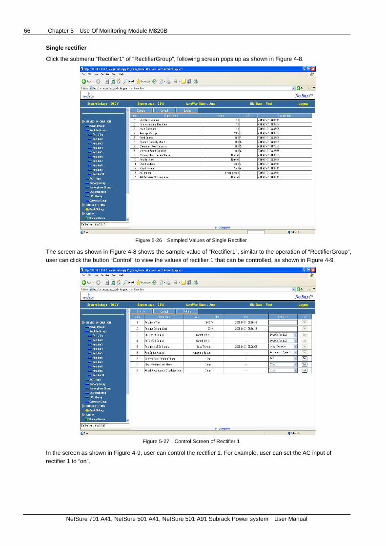
66 Chapter 5 Use Of Monitoring Module M820B
NetSure 701 A41, NetSure 501 A41, NetSure 501 A91 Subrack Power system User Manual
Single rectifier
Click the submenu “Rectifier1” of “RectifierGroup”, following screen pops up as shown in Figure 4-8.
Figure 5-26 Sampled Values of Single Rectifier
The screen as shown in Figure 4-8 shows the sample value of “Rectifier1”, similar to the operation of “RectifierGroup”, user can click the button “Control” to view the values of rectifier 1 that can be controlled, as shown in Figure 4-9.
Figure 5-27 Control Screen of Rectifier 1
In the screen as shown in Figure 4-9, user can control the rectifier 1. For example, user can set the AC input of rectifier 1 to “on”.

Chapter 5 Use Of Monitoring Module M820B 67
NetSure 701 A41, NetSure 501 A41, NetSure 501 A91 Subrack Power system User Manual
5.10.5 Data Browse, Control And Parameter Setting Of Battery
Click the icon in the left of “Battery Group”, all the sampled values of the battery group are displayed as shown in Figure 4-10.
Figure 5-28 Battery Screen (Sampled Value of Battery)
In Figure 4-10, the battery voltage is the total battery string voltage. The battery current is the total battery current. Similar to browse the control values of the rectifier, click the button “Control” to view the control signals of the battery as shown in Figure 4-11.
Figure 5-29 Control the Battery Group
In the screen as shown in Figure 4-11, user can control the battery. For example, in the “Set value” box of “Boost/Float charge control”, user can set the “Float Charge” to “Boost Charge”, and click the button “Set” to make the setting become effective. Click the “Setting” button to view setting signals of the battery as shown in Figure 4-12.

68 Chapter 5 Use Of Monitoring Module M820B
NetSure 701 A41, NetSure 501 A41, NetSure 501 A91 Subrack Power system User Manual
Figure 5-30 Setting Values of Battery Group
In the screen as shown in Figure 4-12, user can set the battery parameters. For example, in the “Set value” box of “Very High Temperature Limit”, user can set the “temperature limit” from “36.00” to “38.00”, and click the button “set” to make the setting become effective.
Click the submenu of “Battery1”, the following screen pops up.
Figure 5-31 Sampled Values of Battery 1
The screen as shown in Figure 4-13 displays the sampled values of battery 1. In this screen, if you click “Control”, nothing will be displayed because it is not allowed to control the single battery or set the values of the single battery.
Click “Setting”, following screen pops up.
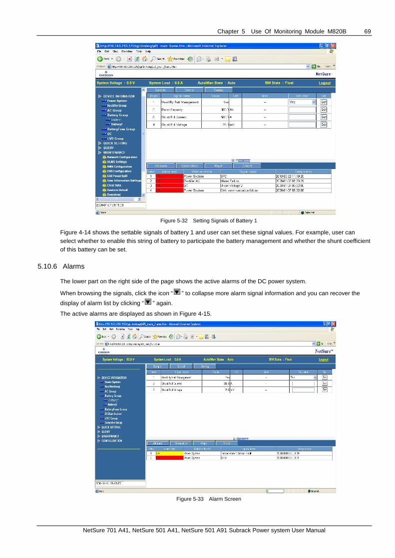
Chapter 5 Use Of Monitoring Module M820B 69
NetSure 701 A41, NetSure 501 A41, NetSure 501 A91 Subrack Power system User Manual
Figure 5-32 Setting Signals of Battery 1
Figure 4-14 shows the settable signals of battery 1 and user can set these signal values. For example, user can select whether to enable this string of battery to participate the battery management and whether the shunt coefficient of this battery can be set.
5.10.6 Alarms
The lower part on the right side of the page shows the active alarms of the DC power system.
When browsing the signals, click the icon “ ” to collapse more alarm signal information and you can recover the
display of alarm list by clicking “ ” again.
The active alarms are displayed as shown in Figure 4-15.
Figure 5-33 Alarm Screen

70 Chapter 5 Use Of Monitoring Module M820B
NetSure 701 A41, NetSure 501 A41, NetSure 501 A91 Subrack Power system User Manual
Figure 4-15 shows all the default alarms in the current active alarm page. Click “Observation Alarm” button to display the alarms that are in the category of “Observation Alarm”.
Figure 5-34 Only Display Minor Alarms
Using the same method, click “Major Alarm” to display all the major alarms, in the same way, click “Critical Alarm” to display all the critical alarms. All the minor alarms are displayed in yellow color and all the major alarms are displayed in red colors and all the critical alarms are displayed in red color.
5.10.7 Maintenance
Click the icon in the left of “Maintenance”, and then click the sub-menu of “Network configuration”, following screen pops up.
Figure 5-35 Network configuration

Chapter 5 Use Of Monitoring Module M820B 71
NetSure 701 A41, NetSure 501 A41, NetSure 501 A91 Subrack Power system User Manual
In the screen as shown in Figure 4-17, user can configure the network parameters of ACU+, such as ACU+ IP address, default gateway and Mask. After modifying the network parameters, click “Save Parameter” to validate the change made to the parameters.
Click the sub-menu of “HLMS Settings”, following screen pops up.
Figure 5-36 HLMS Setting
Click the sub-menu of “NMS Configure”, following screen pops up.
Figure 5-37 NMS Configuration
In the screen as shown in Figure 4-19, user can configure the NMS IP, authority and trap level. User can also add new NMS, modify NMS information and delete the selected NMS through the interface as shown in Figure 4-19. User can also set the trap level.

72 Chapter 5 Use Of Monitoring Module M820B
NetSure 701 A41, NetSure 501 A41, NetSure 501 A91 Subrack Power system User Manual
Click the sub-menu of “ESR Configure”, following screen pops up.
Figure 5-38 ESR Configuration
In the screen as shown in Figure 4-20, user can configure the phone number and protocol for communication.
Click “Edit PowerSplit” submenu, and the following screen shows up.
Figure 5-39 PowerSplit Configurations
In this screen, user can set the PowerSplit mode and Digital input signals. There are some setting parameters, such as delta voltage and proportional coefficient in Menu Power System/Setting for slave system in PowerSplit mode (Refer to 6.3 Power Split Parameters). Note these setting parameters shall be set by expert only, user do not need
to set them.

Chapter 5 Use Of Monitoring Module M820B 73
NetSure 701 A41, NetSure 501 A41, NetSure 501 A91 Subrack Power system User Manual
Click “User Information” submenu, the following screen shows up.
Figure 5-40 Configure User Information
In the screen as shown in Figure 4-22, user can add a user, and the method is as follows.
1. Enter the user name in the box at the right side of “User name”;
2. Select authority of the user;
3. Select the user type;
4. Configure the password for the user;
5. Finally, click “Add” button to add the user.
The method to delete a user is as follows:
(1) Select the user to be deleted in the user list;
(2) Click “Delete user” to delete the user.
The method to modify a user is as follows:
(1) Select the user to be deleted in the user list;
(2) Modify the user information;
(3) Click “Modify the user” to validate the modified user information.
Any user who visits user interfaces of the ACU+, such as LCD, Web interface, Console, shall be assigned with one of the following 5 security levels/user groups.
Table 5-17 User Security Levels
Privilege Level User Group User authority
Level A Browser All users can browse power information without any writing permission.
Level B Operator The operator needs to write one password for control power system
Level C Engineer
The engineer needs to write one password to get the following access: browsing,
control, modifying parameter, downloading configuration file, but except updating
application an OS and modifying, adding, deleting user information (user name, user
level, password).
Level D Administrator
The administrator needs to write one password to get full access that include updating
application an OS and modifying, adding, deleting user information (user name, user
level, password)
Level E Hardware An H/W switch is set that makes no writing of any kind possible to the product
Click the sub-menu of “Time synchronization” to calibrate the clock as shown in the screen below.

74 Chapter 5 Use Of Monitoring Module M820B
NetSure 701 A41, NetSure 501 A41, NetSure 501 A91 Subrack Power system User Manual
Figure 5-41 Time Setting Screen
After changing the time, click “Setting” to validate the new time.
Click the submenu of “Clear Data” to clear the history alarm, history data, control log, battery test log and system operation log.
Select the data to be deleted, click “Clear” to clear the corresponding data.
Figure 5-42 Clear Data

Chapter 5 Use Of Monitoring Module M820B 75
NetSure 701 A41, NetSure 501 A41, NetSure 501 A91 Subrack Power system User Manual
Click “Restore Default Configurations” submenu to restore the default configurations and restart the controller.
Figure 5-43 Restore Default Configurations
Click “Restore Default” and click “OK”, the default configuration files will overwrite the existing configuration files and all the system parameters will be restored to default values.
Then, click “Restart Controller” button to restart the controller to make the default settings become effective.
Note: If the user uses the function of restoring default configurations, the ACU+ will lose its original configurations and existing parameter settings.
Click “Download” submenu to upgrade the application programs, upload the current configuration package and language package.
You need to shut down the controller first.
Figure 5-44 Download File: Shutdown the Controller

76 Chapter 5 Use Of Monitoring Module M820B
NetSure 701 A41, NetSure 501 A41, NetSure 501 A91 Subrack Power system User Manual
Click “Shutdown Controller”, the following interface shows up.
Figure 5-45 Download file
Click “Browse….” button to file the folder where the file will be downloaded. Select the file to be downloaded and then click “Download”.
You can download configuration file package, application file package and language file package through ACU+, but the suffix of the file must be “tar” or “tar.gz”. You can also download the file of “MonitoringSolution.cfg” through ACU+. You cannot download other files through ACU+ except the above files.
You can upload configuration file package and language package through ACU+. In the screen of Figure 4-26, select ‘Configuration File Package” or “Language Package”, click “Upload” to save the configuration file package or language package into the computer.
Click “Start Controller” to restart the controller so as to validate the updated application program.
Click the “Get Parameter Settings” submenu, you can save the parameter settings into the computer and then download the file to other controllers (refer to “Download” menu), so that the other controllers can have the same parameters.

Chapter 5 Use Of Monitoring Module M820B 77
NetSure 701 A41, NetSure 501 A41, NetSure 501 A91 Subrack Power system User Manual
Figure 5-46 Restore Default Configurations
Click “Acquire” button to save the file of SettingParam.run.
Click the “Site Inventory” submenu, you can check the software version, hardware version and serial number information of the intelligent devices (such as rectifier, SMDU and IB board) connected to the ACU+.
Figure 5-47 Restore Default Configurations

78 Chapter 5 Use Of Monitoring Module M820B
NetSure 701 A41, NetSure 501 A41, NetSure 501 A91 Subrack Power system User Manual
5.10.8 Configurations
Click the “Configuration” menu and then select the submenu of “Auto Configuration” to configure the controller automatically.
Figure 5-48 Automatic Configuration
The auto configuration function can detect the intelligent equipment (such as SMDU, IB and EIB) connected to ACU+ and complete relevant configuration.
Click the menu of “Site Information Modification” to change the site name as shown below.
Figure 5-49 Modify Site Name
After entering the site name, site location or site description, click “Set” to modify the site information.

Chapter 5 Use Of Monitoring Module M820B 79
NetSure 701 A41, NetSure 501 A41, NetSure 501 A91 Subrack Power system User Manual
Click the menu of “Equipment Information Modification” to change the name of the device as shown below.
Figure 5-50 Modify Equipment Name
Equipment device has two device names: One is the “Device name” and another is the “Device abbr name”. The “Device name” is displayed in WEB and the “Device abbr name” is displayed in LCD.
Enter the new device name in the column of “New device name”, and select what type of device name will be changed (whether to change the “Device name” or the “Device abbr name”), and finally click “Set”.
Click the menu of “Signal Information Modifcation” to modify the signal names as shown below.
Figure 5-51 Change Information Name
Similar to equipment name, each signal has two signal names: Long signal name and short signal name. The long signal name is displayed in WEB and the short signal name is displayed in LCD.
For example: You can use following procedures to change the “System Name” to “Bus Voltage”.
1. Select the equipment to which this signal belongs: Power system;

80 Chapter 5 Use Of Monitoring Module M820B
NetSure 701 A41, NetSure 501 A41, NetSure 501 A91 Subrack Power system User Manual
2. Select the signal type to which the signal belongs: Acquisition signal
3. Enter new signal name: Bus voltage
4. Select the type of signal name to be changed: Long signal name or short signal name
5. Click “Set” button
For alarm signal, you can also change the alarm level for this alarm signal here.
Figure 5-52 Change Signal Name
In the second step in above procedures, select “Alarm Signal”, then the alarm signal name and alarm level are displayed. Select “New alarm level” and click “Set” to change the alarm level of this alarm signal.
Click the “Configuration of Alarm Suppressing” menu to modify the shielding relationship of the alarm signal as shown below.
Figure 5-53 Alarm Shielding Configuration: Select Standard Equipment

Chapter 5 Use Of Monitoring Module M820B 81
NetSure 701 A41, NetSure 501 A41, NetSure 501 A91 Subrack Power system User Manual
Alarm shielding means: If Alarm A shields Alarm B, when Alarm A happens, Alarm B will not be reported even if the conditions of alarm B are met. For example, AC failure alarm will shield AC low voltage alarm. When AC failure happens, the alarm conditions for both AC failure alarm and AC low voltage alarm are met, and both alarms should be reported. However, since the AC failure alarm shields the AC low voltage alarm, only AC failure alarm is displayed in the alarm list.
First, select the device to which the alarm signal belongs, all the alarm signals of this device will be displayed.
Find the alarm signal to be modified, click “Modify” button, and then set the alarm shield expression, as shown in the Figure below.
Figure 5-54 Alarm Shield Configurations: Select the signal number
After selecting the number of signals in the alarm shield expression (for example, select 2), following screen shows up.
Figure 5-55 Alarm shield configuration: Select alarm shield expression

82 Chapter 5 Use Of Monitoring Module M820B
NetSure 701 A41, NetSure 501 A41, NetSure 501 A91 Subrack Power system User Manual
In this screen, user can select the signals in the alarm shield expression and enter the logic relationship before the alarm signal (Logic AND &, Logic OR |, Logic NO !).
Click “Configuration of PLC” menu to configure the PLC functions of ACU+, as shown below.
Figure 5-56 PLC Configurations
Click “Configuration of Alarm Relay” menu to configure the relevant relays of the alarm signal, as shown in the following figure.
Figure 5-57 Alarm Relay Configurations
Select the standard device first, the screen will display all the alarm signals of this device, as well as the related relay number for each alarm signal. If you need to modify the relay number, click “Modify” button behind the relay number.
“NA” means there is no related relay number.

Chapter 5 Use Of Monitoring Module M820B 83
NetSure 701 A41, NetSure 501 A41, NetSure 501 A91 Subrack Power system User Manual
5.10.9 Query
Click “Query Data” menu, then select “History Alarm” submenu to query the history alarm information.
Figure 5-58 Screen for History Alarm Query
In Figure 4-40, select device (for example, select “Power System”, and the default is “All Devices”), enter the start time and end time, and then click “Query” to query the data within this time slot.
Click “History Data” to pop up the following screen.
Figure 5-59 Query History Data
In Figure 4-41, select the device to be queried, and the default selection is “All Devices”.
Enter the start time and end time (for example, from December 18, 2007 to December 18, 2008), all the log in this time slot will be displayed as shown in the above screen.

84 Chapter 5 Use Of Monitoring Module M820B
NetSure 701 A41, NetSure 501 A41, NetSure 501 A91 Subrack Power system User Manual
Click “ControlSystem Log” to pop up the following screen.
Figure 5-60 Query Control and System Log
In Figure 4-42, first select the type of log to be queried: Control log or system log.
Enter the start time and end time (for example, from December 18, 2007 to December 18, 2008), all the log in this time slot will be displayed as shown in the above screen.
You can save the queried log on your computer: Click “Download”, and select the path to save the query results.
Click “Battery Test Log” button to pop up the following screen.
Figure 5-61 Query Battery Test Data
In Figure 4-43, first enter the latest battery test times; click “Query” to query all the battery test results.

Chapter 5 Use Of Monitoring Module M820B 85
NetSure 701 A41, NetSure 501 A41, NetSure 501 A91 Subrack Power system User Manual
5.11 Access ACU+ Through NMS
ACU+ has SNMP agent function. User can use NMS to do following operations:
Query the operation status and input/output signals of the device connected to ACU+;
Set the operation parameters of the device connected to ACU+;
Browse the active alarms.
When ACU+ generates alarms, SNMP agent can notify the preset NMS through TRAP automatically.
5.11.1 NMS Supported By SNMP Agent
The SNMP agent of ACU+ supports SNMPv2c.
All the NMS that supports SNMPv2c can be used to access ACU+. The NMS includes HP OpenView, IBM NetView, Novell ManageWise, SunNet Manager and so on. SNMP is a technology used for network management. The technology is based on implementing an information base called MIB (Managed Information Base). This MIB contains parameters that are interesting from a management perspective. All LAN connected equipment that support SNMP shall also support a default MIB called MIB-II.
The SNMP Agent responds to requests received via the SNMP protocol and also actively sends traps to a specified manager when certain MIB values change state. This is used to actively inform a manager when an alarm situation is recognized.
5.11.2 MIB Installation
MIB installation
The ACU+ MIB is located in the installation CD delivered together with ACU+, and file name is acu-power.mib.
Use the MIB loading function of NMS to load the MIB database, refer to the corresponding NMS user manual for the detailed loading method.
Contents of MIB
This MIB is suitable for the firmware version 1.10 of ACU+. The MIB will change with the upgrading of ACU+ firmware. The contents of MIB supported by ACU+ SNMP agent, and the OID are listed in Table 5-1. For the details, please refer to the file of acu-power.mib.
Table 5-18 Contents of ACU+ MIB
Ident Group ACU+ ident group
IdentManufacturer The name of the equipment manufacturer R
IdentModel The manufacturers model designation of the power system R
IdentControllerFirmwareVersion The firmware (software) version of the controller R
IdentName The name of the power plant. This object should be set by the administrator. R/W
System Group ACU+ system value group
SystemStatus
Status of the complete plant (highest alarm). One of
(1) unknown - status has not yet been defined
(2) normal - there are no activated alarms (3) warning - OA, lowest level of 'abnormal' status
(4) minor - A3
(5) major - MA
(6) critical - CA, highest level of 'abnormal' status
(7) unmanaged
(8) restricted (9) testing
(10) disabled
R
SystemVoltage System voltage, stored as mV R
SystemCurrent System current, stored as mA R
systemUsedCapacity Used capacity, stored as % of the total capacity R

86 Chapter 5 Use Of Monitoring Module M820B
NetSure 701 A41, NetSure 501 A41, NetSure 501 A91 Subrack Power system User Manual
PsStatusCommunication
The status of communication with the Power System (1) Unknown
(2) normal
(3)interrupt indicates some errors occurred between Power System and agent
PsStatusBatteryMode
The status of battery modes,
(1) Unknown
(2) FloatCharging
(3) ShortTest (4) BoostChargingForTest
(5) ManualTesting
(6) PlanTesting
(7) ACFailTesting
(8) ACFail
(9) ManualBoostCharging (10) AutoBoostCharging
(11) CyclicBoostCharging
(12) MasterBoostCharging
(13) MasterBatteryTesting
SM series group Power system battery group
PsSMACNumber The number of SM AC module R
PsSMBATNumber The number of SM BAT module R
PsSMIONumber The number of SM IO module R
PsInput group Power system input group
PsInputLineAVoltage The AC line A voltage, stored as mV R
PsInputLineBVoltage The AC line B voltage, stored as mV R
PsInputLineCVoltage The AC line C voltage, stored as mV R
PsTemperature Group Power system temperature group
PsTemperature1 The first route temperature, stored as 0.001 Celsius degree R
PsTemperature2 The second route temperature, stored as 0.001 Celsius degree R
Alarm trap Group ACU+ alarm trap Group
alarmLastTrapNo The sequence number of last submitted alarm trap R
AlarmTrapTable
(alarmTrapEntry)
Table holding information about the submitted alarm traps. alarmTrapEntry is the
entry (conceptual row) in the alarmTrapTable R
AlarmTrapNo The unique sequence number of this alarm trap R
AlarmTime Date and time when event occured (local time), including timezone if supported
by controller R
AlarmStatusChange
The type of alarm change. One of
(1) activated
(2) deactivated
R
AlarmSeverity
The severity of the alarm. One of
(1) warning - O1, lowest level of alarm severity
(2) minor - A3 (3) major - A2
(4) critical - A1, highest level of alarm severity
R
AlarmDescription Free-text description of alarm R
AlarmType Alarm type, i.e. an integer specifying the type of alarm
Traps Alarm traps info
The SNMP agent can send the active alarms to the specified NMSs and the user can define the lowest severity of the NMS accepted alarms.
In Table 5-1, R means OID is read-only (GET), and R/W means OID can be read and modified (GET/SET).
5.11.3 Access ACU+ Through NMS
The following part introduces how to access ACU+ with HP OpenView as an example.
Apply Administrative Authority
In order to use NMS to manage the devices connected to ACU+, the administrative authority needs to be applied for the NMS, that is, add the NMS information to the access list of SNMP agent.

Chapter 5 Use Of Monitoring Module M820B 87
NetSure 701 A41, NetSure 501 A41, NetSure 501 A91 Subrack Power system User Manual
Add NMS through Web browser
Refer to “4.4 System Menu” for the method of adding NMS.
5.11.4 ESR Configure
The EEM protocol is used for communication between the Main Computer and the ACU+. The Main Computer is the computer superior to the ACU+ (the client of the ACU+). On this page, all parameters needed for communication with a main EEM computer are to be set.
User information configuaration.
On this page, users, their authority and password are configured.
Time synchronization.
On this page, the system time and date are to be set.
Automatic time synchronization from time servers can also be configured.

88 Chapter 6 Alarm Handling
NetSure 701 A41, NetSure 501 A41, NetSure 501 A91 Subrack Power system User Manual
Chapter 6 Alarm Handling
This chapter describes the handling of alarms, as well as the preventive maintenance of the system during system daily operation.
The maintenance personnel must have adequate knowledge about the power system.
Note
1. The maintenance must be conducted under the guidance of related safety regulations.
2. Only the trained personnel with adequate knowledge about the power system can maintain the inner part of the subrack.
6.1 Handling Alarms
The monitoring module alarms are classified in four types: critical alarm, major alarm, observation and no alarm.
Critical alarm, major alarm: these two types of alarms have strong impacts on the system performance. Whenever these alarms are generated, users are supposed to handle them immediately. The alarm indicators will be on and audible indication will be given.
Observation: when this type of alarm is raised, the system maintains normal output for a while. If the alarm occurs during watch time, it should be handled immediately. If the alarm occurs during non- watch- time, handle it during watch time. The alarm indicators will be on when observation alarm occurs.
No alarm: if alarms are set as ‘no alarm’ by the users, when these alarms occur, no visible or audible indication will be generated and the system works normally.
The handling methods of normal alarms are given in Table 6-1.
Table 6-1 System setting parameter description
No. Alarm Handling method
1 Mains Failure
If the failure does not last long, the battery will power the load. If the cause is unknown or the failure lasts
too long, a diesel generator is needed. Before using the generator power to supply the power system, it
is suggested to run the generator five minutes to minimize the impact on the power system
2 AC Voltage High
Check if the AC over-voltage value is too low. If yes, change the value.
A mild over-voltage does not affect the system operation. However, the rectifier will stop operation when the mains voltage is more than 530V. If the mains voltage is above the AC over-voltage value, the mains
grid should be improved
3 AC Voltage Low
Check if the AC Under- voltage point is too high. If yes, change the value.
When the mains voltage is lower than 304V, the output power of the rectifiers will be derated. And if
lower than 260V, the rectifiers will stop working. If the mains voltage is under the AC under-voltage value,
the mains grid should be improved
4 SPD failure Check the SPD condition. If the SPD is damaged, replace it
5 DC Volt High
Check the DC over-vlotage value through the controller. If the set value is inappropriate, correct it.
Otherwise, find out the rectifier that has caused the alarm: 1. Ensure that the batteries can operate normally.
2. Switch off the AC input of all rectifiers.
3. Power on the rectifiers one by one.
4. If the over-voltage protection is triggered when a certain rectifier is powered on, that rectifier is the
faulty one. Replace it
6 DC Volt Low
1. Check if the alarm is caused by mains failure, if yes, disconnect some loads to prolong the operation of
the whole system. 2. Check the DC under-voltage value set through the controller. If the set value is inappropriate, correct
it.
3. Check if any rectifier is inoperative, or has no output current. If yes, replace it.
4. Check if the total load current exceeds the total rectifier current during float charge. If yes, disconnect
some loads or add more rectifiers to make the total rectifier current bigger than 120% of the total load
current with one redundant rectifier
7 Load Fuse Alarm, Batt Fuse Alarm
Check if the corresponding MCB is switched off. If the MCB is open, find out the fault and remove it. Otherwise, the alarm circuit is faulty. Please contact Emerson

Chapter 6 Alarm Handling 89
NetSure 701 A41, NetSure 501 A41, NetSure 501 A91 Subrack Power system User Manual
No. Alarm Handling method
8 LVD2 1. Check if there is mains failure, and the battery voltage is lower than the value of ‘LVD2’.
2. Check whether the battery is disconnected from the system manually
9 Rect Failure The rectifier with the fault indicator (red) on is faulty.
Power off the rectifier, and then power it on after a while. If the alarm persists, replace the rectifier
10 Rect Protect Check if the mains voltage is above 530V or under 260V. If the mains voltage is under the AC
under-voltage value or above the AC over-voltage value, the mains grid should be improved
11 Rect Fan Fails Pull out the rectifier to check if the fan is obstructed. If yes, clean it and push the rectifier back. If the fan
is not obstructed or if the fault persists after cleaning, replace the fan
12 Rect Not Respond Check if the communication cable is connected properly between rectifier and controller. If yes, restart
the rectifier. If the alarm persists, replace the rectifier
13 Batt Over Temp 1. Check if the battery compartment temperature is too high. If yes, cool down the battery compartment. 2. Check if there is battery internal fault. If yes, replace the faulty battery
6.2 Handling Rectifier Fault
The indicator description, fan and handling methods of all the rectifiers on the system are the same, take R48-1800A and R48-3200 as an example.
Handling indicator fault
The symptoms of usual rectifier faults include: Run indicator (green) off, Protection indicator (yellow) on, Protection indicator blink, Fault indicator (red) on and Fault indicator blink, as shown in Figure 6-1.
R48-1800R48-3200
Run indicatorProtection indicatorFault indicator
Run indicator
Fault indicator
Protection indicator
Figure 6-1 Rectifier indicator
The indicators are shown in Table 6-2.
Table 6-2 Indicator fault description
Symptom Monitoring module
alarms Causes Handling method
Run indicator
off (green) No alarm
No input/output voltage Make sure there is input/output voltage
Assistant power source of the rectifier fails Replace the recitifier
Run indicator
blinks(green) No alarm
The monitoing module performs operations
upon the rectifier No actions need to be taken
Protection
indicator on (yellow)
Rect Protect AC input voltage abnormal Make sure the AC input voltage is normal
Rect Protect
Fan blocked Remove the object that blocks the fan
Ventilation path blocked at the inlet or vent Remove the object at the inlet or vent
Ambient temperature too high or the inlet too
close to a heat source
Decrease the ambient temperature or remove
the heat source
Load share Alarm Current sharing imbalance
Check whether the rectifier communication is
normal. If not, check whether the communication cable is in normal connection.
If the communication is normal while the
protection indicator is on, replace the rectifier
Rect Protect Power factor compensation internal under
voltage or over voltage Replace the rectifier

90 Chapter 6 Alarm Handling
NetSure 701 A41, NetSure 501 A41, NetSure 501 A91 Subrack Power system User Manual
Symptom Monitoring module
alarms Causes Handling method
Protection
indicator
blinks(yellow)
Rect Not Respond Rectifier communication interrupted Check whether the communication cable is in
normal connection
Fault indictor on (red)
Rect HVSD Rectifier over-voltage Reset the rectifier. If the protection is triggered
again, replace the rectifier
Rect Failure Two or more recitifiers have the same ID
number Contact Emerson for maintenance
Rect Failure
Serious current sharing imbalance,
501 series modle: current imbalance > ± 3%;
701 series modle: current imbalance > ± 5%
Check whether the rectifier communication is normal. If not, check whether the
communication cable is in normal connection.
If the communication is normal while the
protection indicator is on, replace the rectifier
Fault indicator
blinks (red) Rect Fan Fails Fan fault Replace the fan
Replacing rectifier fan
If the rectifier fan is faulty and does not work, it should be replaced. Take the R48-1800 rectifiers as an example, the replacement procedures are as follows:
1. Use a cross screwdriver to remove the 3 screws from the fixing holes and pull out the front panel.
2. Unplug the power cable of the fan and remove the fan. Install a new fan.
3. Plug the fan power cable. Put the front panel back and fasten it with the 3 screws, as shown in Figure 6-2.
.
Fan
Front panel Fixing screw of the panel
Fixing screw of the fan
Figure 6-2 Disassembling the front panel
Replacing rectifier
Except replacing the fan, it is recommended not to repair any other part of the module. When faulty, the module should be replaced, not repaired. See the following procedures to replace the rectifier.
1. Take a new rectifier and check it for any damage from transport.
2. Loosen the fixing screw of the handle of the R48-1800A rectifier with a Phillips screwdriver. Pull out the faulty rectifier from the rack by grabbing its handle.
Be careful with the rectifier just pulled out from the system, as it could be very hot due to long-term operation. Do not let it slip away and get damaged.
3. By holding the rectifier handle, push the new rectifier into the slot just vacated and make sure the connection is good. After a brief delay, the rectifier run indicator will turn on and the fan will start running.
4. Check whether the new rectifier works normally. You should make sure that:
1) The monitoring module recognizes the new rectifier.
2) The new rectifier shares current with other rectifiers.
3) When this new rectifier is pulled out, there is a corresponding alarm and the monitoring module displays the alarm.
If the new rectifier passes all the above tests, the replacement is a success.
5. Push the handle back into the front panel to fix the rectifier with the positioning pin. Fix the fixing screw of the handle of the R48-1800 rectifier with a Phillips screwdriver.

Appendix 1 Technical And Engineering Data 91
NetSure 701 A41, NetSure 501 A41, NetSure 501 A91 Subrack Power system User Manual
Appendix 1 Technical And Engineering Data
Table 1 Technical data
Parameter
category Parameter Description
Environmental
Operating temperature -5°C ~ +40°C
Storage temperature -40°C ~ +70°C
Relative humidity 5%RH ~ 95%RH
Altitude ≤ 2,000m (derating is necessary above 2,000m)
Polution level Level 2
Others No conductive dust or erosive gases. No possibility of explosion
AC input
AC input system
NetSure 701 A41-S3/S5, NetSure 501 A41-S1/S2:L+N+
PE/220Vac.
Others: 3P + N + PE/ 380Vac
AC input type TN-C, TN-S, TN-C-S, TT
Input voltage range NetSure 701 A41:85 Vac~290Vac;
NetSure 501 A41, NetSure 501 A91:85Vac~300Vac
Input AC voltage frequency 45Hz ~ 65Hz
Max input current
NetSure 701 A41-S1≤25A; NetSure 701 A41-S2/S4≤45A;
NetSure 701 A41-S3≤90A;NetSure 701 A41-S5≤90A;
NetSure 501 A91-S1≤37A;NetSure 501 A41-S2≤50A;
NetSure 501 A41-S1≤50A
Power factor ≥ 0.99
Over-voltage level Level II
DC output
Standard output DC voltage -48Vdc
Rated output DC voltage -53.5Vdc
Output DC voltage -42.3Vdc ~ -57.6Vdc
Maximum output current
NetSure 701 A41 ≤ 275A, load current ≤ 225A, battery charge current ≤ 50A
NetSure 501 A41≤150A, load current≤ 120A, battery charge
current ≤ 30A
NetSure 501 A91≤275A, load current≤ 225A, battery charge
current ≤ 50A
Voltage set-point accuracy ≤ 1%
Efficiency
R48-1800A/R48-2000≥89%;
R48-2000e/R48-3200e/R48-3500e≥94.5%;
R48-2900U≥90%; R48-4000e≥90%
Noise (peak-peak) ≤ 200mV (0 ~ 20MHz)
Weighted noise ≤ 2mV (300 ~ 3400Hz)
AC input alarm
and protection
AC input over-voltage alarm point Default: 280 ± 5Vac, cofigurable through monitoring module
AC input over-voltage alarm recovery
point
Default: 270 ± 5Vac, 10Vac lower than the AC input over-voltage
alarm point
AC input under-voltage alarm point Default: 180 ± 5Vac, configurable through monitoring module
AC input under-voltage alarm recovery
point
Default: 190 ± 5Vac, 10Vac higher than the AC input under-voltage
alarm point
AC input over-voltage protection point
NetSure 501 A41, NetSure 501 A91: 305 ± 5Vac by default, cofigurable through monitoring module
NetSure 701 A41: 295 ± 5Vac by default, cofigurable through
monitoring module
AC input over-voltage protection
recovery point
NetSure 501 A41, NetSure 501 A91: 295 ± 5Vac by default, 10Vac
lower than the AC input over-voltage alarm point
NetSure 701 A41: 285 ± 5Vac by default, 10Vac lower than the AC
input over-voltage alarm point

92 Appendix 1 Technical And Engineering Data
NetSure 701 A41, NetSure 501 A41, NetSure 501 A91 Subrack Power system User Manual
Parameter
category Parameter Description
AC input alarm
and protection
AC input under-voltage protection point Default: 80 ± 5Vac, configurable through monitoring module
AC input under-voltage protection
recovery point
Default: 95 ± 5Vac, 10Vac higher than the AC input under-voltage
alarm point
DC output alarm
and protection
DC output over-voltage alarm point Default: -58.0 ± 0.2Vdc, configurable through monitoring module
DC output over-voltage recovery point Default: -57.5 ± 0.2Vdc, 0.5Vdc lower than the over-voltage alarm
point
DC output under-voltage alarm point Default: -45.0 ± 0.2Vdc, configurable through monitoring module
DC output alarm
and protection
DC output under-voltage recovery point Default: -45.5 ± 0.2Vdc, 0.5Vdc higher than the under-voltage alarm
point
DC output over-voltage proteciton point Default: -59.0 ± 0.2Vdc, configurable through monitoring module
LLVD Default: -44.0 ± 0.2Vdc, configurable through monitoring module
BLVD Default: -43.2 ± 0.2Vdc, configurable through monitoring module
Rectifier
Current sharing The rectifiers can work in parallel and share the current. The
unbalanceness is better than ± 5%
Derate by input (at 45°C)
R48-1800A、R48-2000、R48-2000e:
176Vac input, The rectifier outputs max.power: 100%
85Vac input, The rectifier outputs max. power: 40%
80Vac input, The rectifier low pressure power off
R48-3200、R48-2900U、R48-3500e、R48-3000e:
176Vac input, The rectifier outputs 100% power
120Vac input, The rectifier outputs 50% power 85Vac input, The rectifier outputs 18.75% power
80Vac input, The rectifier low pressure power off
R48-4000e:
207Vac input, The rectifier outputs 100% power
120Vac input, The rectifier outputs 2200W power
85Vac input, The rectifier outputs 1500W power 80Vac input, The rectifier low pressure power off
Output delay Output voltage can rise slowly upon rectifier start up. The rise time
is configurable
Fan speed adjustable Rectifier fan speed can be set to half or full speed
Over-voltage protection
The rectifier provides over-voltage hardware and software
protection. The hardware protection point is 59.5V ± 0.5V, and it
requires manual resetting to restore operation. The software
protection point is between 56V and 59V (0.5V above output
voltage, 59V by default), and can be set through the monitoring module
There are two software protection modes, which can be selected
through the software at the host:
1. Lock out at the first over-voltage
Once the output voltage reaches protection point, the rectifier will
shut off and hold that state. It requires manual resetting to restore the operation
2. Lock out at the second over-voltage
When the output voltage reaches the software protection point, the
rectifier will shutdown, and restart automatically after 5 seconds. If
the over-voltage happens again within a set time (default: 5min.
Configurable through monitoring module), the rectifier will shut off and hold that state. It requires manual resetting to restore the
operation
Manual resetting: Resetting can be done manually through the
monitoring module, or by removing the rectifier from system

Appendix 1 Technical And Engineering Data 93
NetSure 701 A41, NetSure 501 A41, NetSure 501 A91 Subrack Power system User Manual
Parameter
category Parameter Description
Rectifier Temperature derating
R48-1800A:
Temperature below 45°C, outputs full power
Temperature above 45°C, there will be linear deratin g, that is:
At 55°C, output power is 1,600W
At 65°C, output power is 1,500W At 75°C, output power is 800W
At 80°C, output power is 0
R48-2000、R48-2000e:
Starts at -40°C; Temperature below 45°C, outputs fu ll power
Temperature above 45°C, there will be linear deratin g, that is:
At 55°C, output power is 1,750W
At 65°C, output power is 1,600W
At 70°C, output power is 800W
At 75°C, output power is 0 R48-3000e:
At the ambient temperature of:
Below 45°C, outputs full power: 3,000W
Above 45°C, there will be linear derating, that is:
At 55°C, output power ≥ 2,400W
At 60°C, output power ≥ 1,500W At 65°C, output power: 0
R48-3200:
Starts at -40°C; Temperature below 45°C, outputs po wer is 3200W.
Temperature above 45°C, there will be linear deratin g, that is:
At 65°C, output power is 2,320W
At 70°C, output power is 1,450W At 75°C, output power is 0
R48-2900U:
Starts at -40°C; Temperature below 45°C, outputs po wer is 2900W.
Temperature above 45°C, there will be linear deratin g, that is:
At 55°C, output power is 2,320W
At 60°C, output power is 1,450W At 65°C, output power is 0
R48-3500e:
Starts at -40°C; Temperature below 45°C, outputs po wer is 3500W.
Temperature above 45°C, there will be linear deratin g, that is:
At 50°C, output power is 3200W;
At 55°C, output power is 2900W; At 65°C, output power is 2320W;
At 70°C, output power is 1450W.
At 75°C, output power is 0
R48-4000e:
Starts at -40°C; Temperature below 50°C, outputs po wer is 4000W.
Temperature above 45°C, there will be linear deratin g, that is: At 55°C, output power is 3500W;
At 65°C, output power is 3000W;
At 75°C, output power is 2400W
EMC
Conducted emission Class A EN55022
Radiated emission
Voltage fluctuation and flash Class A EN61000-3-11
Immunity to EFT Level 4 EN/IEC 61000-4-4
Immunity to ESD Level 3 EN/IEC 61000-4-2
Immunity to surges Level 4 EN/IEC 61000-4-5
Immunity to radiation Level 2 EN/IEC 61000-4-3
Immunity to conduction Level 2 EN/IEC 61000-4-6

94 Appendix 1 Technical And Engineering Data
NetSure 701 A41, NetSure 501 A41, NetSure 501 A91 Subrack Power system User Manual
Parameter
category Parameter Description
Lightning
protection
features
At AC side
The AC input side can withstand five times of simulated lightning
voltage of 5Kv at 10/700µs, for the positive and negative polarities
respectively. It can withstand five times of simulated lightning surge
current of 20Ka at 8/20µs, for the positive and negative polarities
respectively. The test interval is not smaller than 1 minute. It can also withstand one event of simulated lightning surge current of
40Ka at 8/20µs
Others
Safety regulation IEC60950-1:2001
Acoustic noise ≤ 60db (A) (When the ambient temperature is lower than25)
Insulation resistance
At temperature of 15°C ~ 35°C and relative humidity n ot bigger than
90%RH, apply a test voltage of 500Vdc. The insulation resistances between AC circuit and earth, DC circuit and earth, and AC and DC
circuits are all not less than 10MΩ
Insulation strength
(Remove the SPD, monitoring module and rectifiers from the system
before the test.) AC loop to DC loop can withstand 50Hz.
DC circuit to earth: 50Hz, 2,500Vac; or 3535Vdc;
AC to DC circuits: 50Hz, 1,000Vac; or 1414Vdc;
Assistant circuit (not directly connected to the host circuit): 50Hz, 500Vac
For all the three tests above, there should be no breakdown or
flashover within 1min, with leakage current not bigger than 10Ma;
MTBF > 200,000hr
ROHS Compliant with R5 requirement
Mechanical
Dimensions
(mm)(W×D×H)
Maximum dimensions
of the subracks
NetSure 501 A41-S1/S2: 483 × 360 × 223
NetSure 501 A91-S1: 483 × 360 × 445
NetSure 701 A41-S1/S2/S3/S5: 483 × 360 × 267
NetSure 701 A41-S4: 483 × 360 × 400.5
Monitoring module M501D/ M500D
85 × 85 × 287
Rectifier
R48-1800A, R48-2000, R48-2000e: 87.9× 85.3× 272
R48-3000e, R48-3200, R48-2900U, R48-3500e: 132.3 × 88× 294
R48-4000e:132.3 × 88 × 294
Weight (kg)
Subrack (without
rectifiers and
monitoring module)
≤ 25
Monitoring module
M501D/M500D < 0.8
Rectifier R48-1800A, R48-2000, R48-2000e ≤ 2.0 R48-3200, R48-2900U, R48-3200, R48-3500e, R48-4000e ≤ 3.5
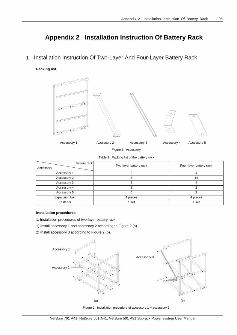
Appendix 2 Installation Instruction Of Battery Rack 95
NetSure 701 A41, NetSure 501 A41, NetSure 501 A91 Subrack Power system User Manual
Appendix 2 Installation Instruction Of Battery Ra ck
1. Installation Instruction Of Two-Layer And Four-Layer Battery Rack
Packing list
Accessory 1 Accessory 2 Accessory 3 Accessory 4 Accessory 5
Figure 1 Accessory
Table 2 Packing list of the battery rack
Battery rack
Accessory Two-layer battery rack Four-layer battery rack
Accessory 1 2 4
Accessory 2 8 14
Accessory 3 2 4
Accessory 4 2 2
Accessory 5 0 2
Expansion bolt 4 pieces 4 pieces
Fastener 1 set 1 set
Installation procedures
1. Installation procedures of two-layer battery rack
1) Install accessory 1 and accessory 2 according to Figure 2 (a).
2) Install accessory 3 according to Figure 2 (b).
Accessory 1
Accessory 2
Accessory 3
(a) (b)
Figure 2 Installation procedure of accessory 1 ~ accessory 3

96 Appendix 2 Installation Instruction Of Battery Rack
NetSure 701 A41, NetSure 501 A41, NetSure 501 A91 Subrack Power system User Manual
3) Install accessory 2 and accessory 4 according to Figure 3.
Accessory 4
Accessory 2
Figure 3 Installation procedure of accessory 2 and accessory 4
2. Installation procedures of four-layer battery rack
1) Install accessory 1, accessory 2 and accessory 3 according to Figure 2 (a) and Figure 2 (b).
2) Install accessory 5 according to Figure 4 (a).
3) Install accessory 2 and accessory 4 according to Figure 4 (b).
Accessory 4
Accessory 2
(a) (b)
Figure 4 Installation procedure of accessory 2, accessory 4 and accessory 5

Appendix 2 Installation Instruction Of Battery Rack 97
NetSure 701 A41, NetSure 501 A41, NetSure 501 A91 Subrack Power system User Manual
2. Installation Instruction Of Three-Layer Battery Rack
Packing list
Accessory 1 Accessory 2 Accessory 3 Accessory 4
Figure 5 Accessory
Table 3 Packing list of the battery rack
Accessory Accessory number
Accessory 1 2
Accessory 2 6
Accessory 3 3
Accessory 4 2
Expansion bolt 4 pieces
Fastener 1 set
Installation procedures
1. Install accessory 1 and accessory 2 according to Figure 6 (a).
2. Install accessory 3 according to Figure 6 (b).
Accessory 1
Accessory 2
Accessory 3
(a) (b)
Figure 6 Installation procedure of accessory 1 ~ accessory 3
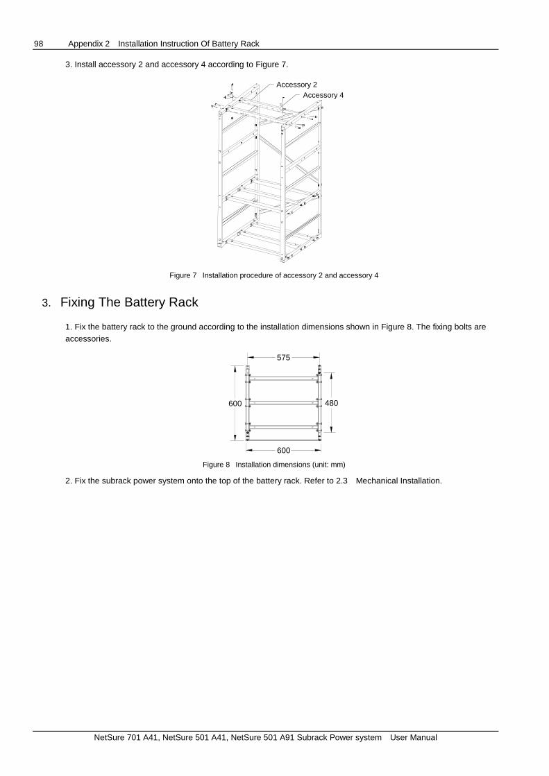
98 Appendix 2 Installation Instruction Of Battery Rack
NetSure 701 A41, NetSure 501 A41, NetSure 501 A91 Subrack Power system User Manual
3. Install accessory 2 and accessory 4 according to Figure 7.
Accessory 4Accessory 2
Figure 7 Installation procedure of accessory 2 and accessory 4
3. Fixing The Battery Rack
1. Fix the battery rack to the ground according to the installation dimensions shown in Figure 8. The fixing bolts are accessories.
600
600
575
480
Figure 8 Installation dimensions (unit: mm)
2. Fix the subrack power system onto the top of the battery rack. Refer to 2.3 Mechanical Installation.

Appendix 3 Wiring Diagram 99
NetSure 701 A41, NetSure 501 A41, NetSure 501 A91 Subrack Power system User Manual
Appendix 3 Wiring Diagram
B
MFU8 Rear top view
12
3 5-3 W07
2 11 2
PL
Shelf 16
Module subrack Rear view
1
2
1
2
7-30
QF
B1
QF
B2
7-28
7-20
7-22
7-41
7-39
7-2W05
7-4
W80
Controller motherboard switch
8-B-
1
2
1
2 QF
D1
QF
D21
2QF
D31
2QF
D16
PL
0V
To the positive Busbar
PE5
M221S7
To the Negative Busbar
1
BUS+9
RB10
KM212
2
9-2
1
215-J71
W80+W81+W827-29
W80 W80
W80W80
W80
W05
X3-1
W807-35/7-47/7-49/7-50
7-44
7-467-31
6 6 6
1 1 1
6
1
PEPE PE PEN
L
P
N
L
P
N
L
P
N
L
PW04 W04 W04 W04
W01 W01 W01 W01
4 5
32
4 5
32
4 5
32
4 5
32
24H4
23H3
22H2
21H1
6 6 6
1 1 1
6
1
PEPE PE PEN
L
P
N
L
P
N
L
P
N
L
PW04 W04 W04 W04
4 5
32
4 5
32
4 5
32
4 5
32
28H8
27H7
26H6
25H5
6
1
PEN
L
P W04
4 5
32
29H9
W01 W01 W01 W01 W01
W02 W02 W02 W02
W02 W02 W02 W02 W02
DU17
0V
Rear view
PL
8-Q
F1
7
8-Q
F1
8
1
2
1
2
W81+W82
To MFU positive expansion busbar
7-29
12
34
56
78
910
1112
1314
1516
1718
1920
2122
2324
2526
2728
2930
3132
3334
3536
3738
3940
4142
4344
4546
4748
4950
13-J
8-1
24
-CA
N-
11-2
11-1
24-C
AN
+
13-J
7-1
13-J
7-2
13-J
8-2
13-J
8-3
13-J
8-5
13-
J8-4
13-
J8-6
13-J
8-7
13-J
8-8
8-Q
FB
2-1
8-Q
FB
1-1
10-2
10-1
W80
W80
W80 W80
W80 W80
W80X3-2
W809-BUS+-1
X6-1 X5-1
8-B
--1
W80
8-P
L-1
W80 9-B
US
+-1
W80
W80
8-P
L-1
W80X7-2
W80
W809-BUS+-2
2 W80X5-1/X6-1
Three-phase AC input
L2L1 L31 3 5 7
2 4 6 8
N
QFA1
21-L
/24
-L/2
7-L
22-L
/25-
L/2
8-L
23-L
/26-
L/2
9-L
W01 W01W01
13
W2453X1
W2453X1
J621
J31+1-
2+2
-
J81 8
W80
J71 2
J43+3-
4+
4-
DO
3 DO
4DO
1
DO
2
21-N
/22
-N/2
3-N
/24
-N
W02
25-N
/26
-N/2
7-N
/228
-N/2
9-N
4
8-P
L-Q
FD
8-N
PL-
QF
D
DU power unit
TO DU unit PL bar
User interface board 11
MFU door connected ground
TO MFU unit PL busbar
TO the user
protective
earth
To the positive busbar of the MFU
TO MFU unit PL busbar
Front view
MFU DC power
wiring diagram
Figure 9 NetSure 501 A91-S1 wiring diagram

Appendix 3 Wiring Diagram 100
NetSure 701 A41, NetSure 501 A41, NetSure 501 A91 Subrack Power system User Manual
MFU8
13
W2453X1
W2453X1
J621
J31+1-
2+2-
J81 8
W80J7
12
12
34
56
78
910
1112
1314
1516
1718
1920
2122
2324
2526
2728
2930
3132
3334
3536
3738
3940
4142
4344
4546
4748
4950
13-
J8-1
24-
CA
N-
18-
J1-1
11-
2
11-
1
24-C
AN
+
13-J
7-1
13-
J7-2
X10-2
13-J
8-2
13-J
8-3
13-J
8-5
13-J
8-4
13-J
8-6
13-J
8-7
13-
J8-8
8-Q
FB
1-2
8-Q
FB
2-2
8-Q
FB
3-2
8-Q
FB
4-2
10-2
10-1
9-B
US
+-1
W80
W80
W80 W80W80W80
W80W80 W80
W80
W80X3-2
W809-BUS+-1
X6-1 X5-1
8-P
L-1
W80 9-B
US
+-1
W80
W80
8-P
L-1
2
J2123
J11
18
M34C3C1
7-397-41
12-112-2
8-PL-1
18-J
1-2
Single-phase AC input(SPD)
8-P
L-2
W06
5-2
W80X7-2
Shelf 16
Rear view
7-2W05
7-4X3-1
6 6 6
1 1 1
6
1
PEPE PE PEN
L
P
N
L
P
N
L
P
N
L
PW04 W04 W04 W04
W01 W01 W01 W01
4 5
32
4 5
32
4 5
32
4 5
32
24H4
23H3
22H2
21H1
W02 W02 W02 W02
J6J3
15
M2433X2
J7J5J1 J2 J4
v-v+PE
W06
9-2
W06
L1 3
2 4
N
QFA1
W01 W02
L
N
SPD12
1-4
QFA23
PE
W03
W03
W03X10-1
21
-N/2
4-N
22-
N2
3-N
21
-L/2
4-L
22
-L2
3-L
LO1 3
2 4
NO
2-NW032-
N1-
2
3-4
3-2W03Conneted earthing terminal
J43+3-
4+4-
DO
3
DO
4DO
1
DO
2
DCSPD
13-
J3-1
+
13-
J3-1
-
15-J4-1
15-J4-2
W06
W06
W06
W03W03
12 3 5-3 W07
2 112
PL
1
2
1
2
7-2
4Q
FB
1
QF
B2
7-2
6
7-20
7-22
18-J
2-1
18-
J2-2
W80
W80
15-J5W06
2-PE W03
12
7-4
5
7-43
NPL
8-B-
1
2
1
2 QF
D1
QF
D21
2QF
D31
2QF
D4
NPL
1
2
1
2 QF
D5
QF
D6
PL
0VPE5
1
BUS+9
RB10
KM111
KM212
2
9-2
1
215-J7
1
7-35
W807-297-27
W80
W80W80
W80
W80
W80W06
W807-47/7-49/7-50
7-467-31
9-B
US
+-1
18-J2-3
15-J6W0612-1 W84
W84
Controller motherboard switch Front view
MFU DC power
wiring diagram Rear top view
Module subrackTO MFU unit PL busbar To the positive busbar of the MFU
To the positive Busbar
TO the user protective
earth
To the Negative Busbar
User interface board 1
M221S7
User interface board 1
Figure 10 NetSure 501 A41-S1 wiring diagram

Appendix 3 Wiring Diagram 101
NetSure 701 A41, NetSure 501 A41, NetSure 501 A91 Subrack Power system User Manual
MFU8
M820B7
12
34
56
78
910
1112
1314
1516
1718
1920
2122
2324
2526
2728
2930
3132
3334
3536
3738
3940
4142
4344
4546
4748
4950
24-C
AN
-
24-C
AN
+
13-J
2-3
13-J
2-4
13-J
2-1
8-Q
FB
1-1
8-Q
FB
2-1
10-2
10-1
W80 W80
W80X3-2
W809-BUS+-2
X6-1 X5-1
8-B
--1
W80
8-PL
-1
W80 9-B
US
+-1
W80
W80
8-P
L-1
5152
5354
5556
5758
5960
6162
6364
6566
6768
6970
7172
7374
7576
7778
7980
8182
8384
8586
8788
8990
9192
9394
9596
9798
99100
13-J
2-2
X9
12-2
11-2
W80
W80
W80W80
W80
J2J11 J12
J3J4
J5J6
J7J8
J9
13
IB2
12
4 3
11-1
W80
12-1
W80
W80
X12-2
至用户保护地 12
3 5-3 W07
2 11 2
PL
1
2
1
2
7-55
QFB
1
QF
B2
7-56
7-20
7-22
7-80
7-82
W80
8-B-
1
2
1
2 QF
D5
QF
D61
2QF
D71
2QF
D8
PL
0VPE5
1
BUS+9
RB10
KM212
2
9-2
1
2
1
W82+W81+W807-59
W80 W80
W80W80
W807-35/7-47/7-49/7-50
7-44
7-467-31 NPL
1
2
1
2 QF
D1
QF
D21
2
1
2 QF
D3
QF
D4
NPL
7-60
1
7-79
W80
2
7-81
KM111
W80
Shelf 16
7-2W05
7-4X3-1
6 6 6
1 1 1
6
1
PEPE PE PEN
L
P
N
L
P
N
L
P
N
L
PW04 W04 W04 W04
W01 W01 W01 W01
4 5
32
4 5
32
4 5
32
4 5
32
24H4
23H3
22H2
21H1
W02 W02 W02 W02
L1 3
2 4
N
QFA1
W01 W02
21-L
/24-
L22
-L23
-L
21-N
/24-
N22
-N23
-N
42
3
W809-BUS+-1
W80X5-1/X6-1
W82+W81+W80
W80
W80
8-N
PL
-QF
D
8-P
L-Q
FDController motherboard switch
Rear top view
MFU DC power
wiring diagram
Rear top viewModule subrack
TO MFU unit PL busbar To the positive busbar of the MFU
Single-phase AC input
To the positive Busbar
To the Negative Busbar
User interface board 1
Door connected ground
Figure 11 NetSure 501 A41-S2 wiring diagram

Appendix 3 Wiring Diagram 102
NetSure 701 A41, NetSure 501 A41, NetSure 501 A91 Subrack Power system User Manual
MFU8
1
23 5-3 W07
2 11 2
PL
1
2
1
2
7-30
QF
B1
QF
B2
7-28
7-20
7-22
7-41
7-39
W8012
7-4
5
7-4
3
NPL
8-B-
1
2
1
2 QF
D1
QF
D21
2
1
2 QF
D3
QF
D4
NPL
1
2QF
D5
PL
0VPE5
M221S7
1
BUS+9
RB10
KM111
KM212
2
9-2
1
2
1
W80+W81+W827-277-29
W80
W80W80
W80
W80W80
W80
W807-35/7-47/7-49/7-50
7-44
7-467-31
L2L1 L31 3 5 7
2 4 6 8
N
21-
L
21-
N/2
2-N
/23-
N
W01 W01W01
W02
QFA1
22-
L
23-
L
23H3 H 2
22H121
1
10
1
10
1
10
Shelf 16
0V
-48V
L
N
PE
L
N
PE
L
N
PE
7-2
W057-4W04 W04 W04
W01
W02
W01
W02
W01
W02
X3-1
12
34
56
78
910
1112
1314
1516
1718
1920
2122
2324
2526
2728
2930
3132
3334
3536
3738
3940
4142
4344
4546
4748
4950
13-J
8-1
24-C
AN
-
11-
2
11-
1
24-C
AN
+
13-J
7-1
13-
J7-2
13-J
8-2
13-
J8-3
13-J
8-5
13-J
8-4
13-
J8-6
13-
J8-7
13-
J8-8
8-Q
FB
1-1
8-Q
FB
2-1
10-2
10-
1
W80
W80
W80W80
W80W80
W80X3-2
W809-BUS+-2
X6-1 X5-1
8-B
--1
W80
8-P
L-1
W80
9-B
US
+-1
W80
W80
8-P
L-1
W80X7-2
W80
12-2
12-1
W80 W80
W80
W80+W81+W82
4 2
3
W809-BUS+-1
X5-1/X6-1 W80
13
W2453X1
W2453X1
J621
J31+
1-
2+
2-
J81 8
W80
J712
J43+3-
4+4
-
DO
3
DO
4DO
1
DO
2
8-P
L-Q
FD
8-N
PL-
QF
D
TO the user protective
earth
MFU DC power
wiring diagram Rear top view
Controller motherboard switch Front view
Module subrackTO MFU unit PL busbar To the positive busbar of the MFU
Three-phases AC input
MFU Door connected ground
To the positive Busbar
To the Negative Busbar
Figure 12 NetSure 701 A41-S1 wiring diagram

Appendix 3 Wiring Diagram 103
NetSure 701 A41, NetSure 501 A41, NetSure 501 A91 Subrack Power system User Manual
MFU8
M221S7
L2L1 L31 3 5 7
2 4 6 8
N
21-L
/24/
L
21-N
/22-
N/2
3-N
/24-
N
W01 W01W01 W02
QFA1
22-L
23-L
12
34
56
78
910
1112
1314
1516
1718
1920
2122
2324
2526
2728
2930
3132
3334
3536
3738
3940
4142
4344
4546
4748
4950
13-J
8-1
24-C
AN
-
11-
2
11-
1
24-C
AN
+
13-J
7-1
13-J
7-2
13-J
8-2
13-J
8-3
13-J
8-5
13-
J8-4
13-
J8-6
13-J
8-7
13-J
8-8
8-Q
FB
1-1
8-Q
FB
2-1
10-2
10-1
W80
W80
W80 W80
W80 W80
W80X3-2
W809-BUS+-2
X6-1 X5-1
8-B
--1
W80
8-P
L-1
W80 9-B
US
+-1
W80
W80
8-P
L-1
W80X7-2
W80
23H3
24H4 H2
22H121
1
10
1
10
1
10
1
10
Shelf 16
0V
-48V
L
N
PE
L
N
PE
L
N
PE
L
N
PE
7-2
W057-4W04 W04 W04 W04
W01
W02
W01
W02
W01
W02
W01
W02
X3-1
W809-BUS+-1
12
3 5-3 W07
2 11 2
PL
1
2
1
2
7-3
0Q
FB
1
QF
B2
7-2
8
7-20
7-22
7-41
7-39
W80
8-B-
1
2
1
2 QF
D1
QF
D21
2QF
D31
2QF
D12
PL
0VPE5
1
BUS+
9
RB10
KM212
2
9-2
1
2
1
W80+W81+W827-29
W80 W80
W80W80
W80
W807-35/7-47/7-49/7-50
7-44
7-467-31
4 2
W80
X5-1/X6-1 W803
13
W2453X1
W2453X1
J621
J31+1-
2+2-
J81 8
W80J7
12
J43+3-
4+4-
DO
3
DO
4DO
1
DO
2
8-P
L-Q
FD
8-N
PL
-QF
D
TO the user protective
earth
MFU DC power
wiring diagram Rear top view
Controller motherboard switch Front view
User interface board 1
Module subrackTO MFU unit PL busbar To the positive busbar of the MFU
To the positive Busbar
To the Negative Busbar
MFU Door connected ground
Three-phases AC input
Figure 13 NetSure 701 A41-S2 wiring diagram

Appendix 3 Wiring Diagram 104
NetSure 701 A41, NetSure 501 A41, NetSure 501 A91 Subrack Power system User Manual
MFU8
12
3 5-3 W07
2 11 2
PL
1
2
1
2
7-30
QF
B1
QF
B2
7-28
7-20
7-22
18-
J2-1
18-
J2-2
W80
W80
15-J6W06
2-PEW03
12
7-4
5
7-43
NPL
12
34
56
78
910
1112
1314
1516
1718
1920
2122
2324
2526
2728
2930
3132
3334
3536
3738
3940
4142
4344
4546
4748
4950
13-J
8-1
24-
CA
N-
8-B-
1
2
1
2 QF
D1
QF
D21
2QF
D31
2QF
D8
NPL
1
2
1
2 QF
D9
QF
D1
01
2
1
2 QF
D1
1
QF
D12
PL
0VPE5
M221S7
1
BUS+9
RB10
KM111
KM212
18-J
1-1
11-2
11-1
2
9-2
1
215-J7
24-
CA
N+
13-J
7-1
13-J
7-2
X10-2
13-J
8-2
13-J
8-3
13-J
8-5
13-J
8-4
13-J
8-6
13-J
8-7
13-J
8-8
8-Q
FB
2-1
8-Q
FB
1-1
10-2
10-1
1
W80
W80
W807-277-29
W84
W80W80
W84
W84 W84 W80W80
W80W80 W80
W80
W80
W06
W80X3-2
W809-BUS+-2
X6-1 X5-1
W807-35/7-47/7-49/7-50
7-46
8-P
L-1
W80 9-B
US
+-1
W80
W80
8-P
L-Q
FD
7-31
9-B
US
+-3
18-J2-3
18-J
1-2
W80X7-2
Shelf 16
L1 3
2 4
N
QFA1
W01 W02
L
N
SPD12
1-4
QFA23
PE
W03
W03
W03X10-1
21
-N/2
4-N
22-
N23
-N
21-L
/24
-L22
-L23
-L
LO1 3
2 4
NO
2-NW03
2-N
1-2
3-4
3-2W03
5-4W03W03
8-P
L-2
W06
5-2
J6J3
15M2433X2
J7J5J1 J2 J4
v-v+PE
W06
9-2
W06
DCSPD
13-J
3-1
+
13-J
3-1
-W06
13
W2453X1
W2453X1
J621
J31+
1-
2+
2-
J81 8
W80
J712
J43+
3-
4+
4-
DO
3
DO
4DO
1
DO
2
15-J4-1
15-J4-2
W06
W06
2
J2123
J1
1
18
M34C3C1
7-397-41
12-112-2
8-PL-1
415-J6W06
12-1W84
W84
W84W84
23H3
24H4 H2
22H121
1
10
1
10
1
10
1
10 0V
-48V
L
N
PE
L
N
PE
L
N
PE
L
N
PE
7-2
W057-4W04 W04 W04 W04
W01
W02
W01
W02
W01
W02
W01
W02
X3-123
W80
W84
W809-BUS+-1
X5-1/X6-1 W80
8-N
PL-
QF
D
8-P
L-1
TO the user protective
earth
MFU DC power
wiring diagram Rear top view
Controller motherboard switch Front view
User interface board 1
Module subrackTO MFU unit PL busbar To the positive busbar of the MFU
Single-phase AC input
Door connected ground
To the positive Busbar
To the Negative Busbar
Figure 14 NetSure 701 A41-S3 wiring diagram

Appendix 3 Wiring Diagram 105
NetSure 701 A41, NetSure 501 A41, NetSure 501 A91 Subrack Power system User Manual
DU17
0V
DU 后视图
NPL
MFU8
Shelf 16
8-Q
F6
8-Q
F51
2
1
2
L2L1 L31 3 5 7
2 4 6 8
N
W81+W82
QFA1
21-L
/24-
L
22-L
23-L
21-N
22-N
23-N
24-N
W01 W01 W01 W0212
34
56
78
910
1112
1314
1516
1718
1920
2122
2324
2526
2728
2930
3132
3334
3536
3738
3940
4142
4344
4546
4748
4950
24-C
AN
-
M820B7
至 正极扩展排
12-1
11-1
24-C
AN
+
13-J
2-3
13-J
2-4
13-J
2-1
8-Q
FB
1-1
8-Q
FB
2-1
10-2
10-1
W80
W80W80
W80X3-2
W809-BUS+-2
X4-2 X5-1
8-B
--1
W80
8-PL
-1
W80 9-B
US+
-1
W80
W80
8-P
L-1
7-60
5152
5354
5556
5758
5960
6162
6364
6566
6768
6970
7172
7374
7576
7778
7980
8182
8384
8586
8788
8990
9192
9394
9596
9798
99100
J2J11 J12
J3J4
J5J6
J7J8
J9
13IB2
12
4 313-J
2-2
X9
12-1
11-2W80
W80 W80W80
W80
W80
W80
8-Q
F71
28-Q
F81
2
X12
23H3
24H4 H2
22H121
1
10
1
10
1
10
1
10 0V
-48V
L
N
PE
L
N
PE
L
N
PE
L
N
PE
7-2
W057-4W04 W04 W04 W04
W01
W02
W01
W02
W01
W02
W01
W02
X3-1
12
3 5-3 W07
2 11 2
PL
1
2
1
2
7-55
QF
B1
QF
B2
7-56
7-20
7-22
7-80
7-82
W80
W8012
7-79
7-81
NPL
8-B-
1
2
1
2 QFD
1
QF
D2
NPL
1
2
1
2 QFD
9
QFD
101
2QFD
11
1
2QF
D18
PL
0V
至模块正极排
PE5
至模块负极排
1
BUS+9
RB10
KM111
KM212
2
9-2
1
2
1
W807-607-59
W80
W80W80
W80
W80W80
W80
W807-35/7-47/7-49/7-50
7-44
7-467-31
4
W809-BUS+-1
2
3X5-1/X6-1 W80
W80
至 单元 排
8-Q
F4
8-Q
F31
2
1
2
8-P
L-Q
FD
8-N
PL-Q
FD
PL
DU NPL
至 单元 排DU PL
配电单元
MFU
TO the user protective
earth
MFU DC power
wiring diagram
Rear top view
Controller motherboard switch Front view
User interface board 1
Module subrack
TO MFU unit PL busbar To the positive busbar of the MFU
Three-phases AC input
MFU Door connected ground
TO MFU unit PL busbar To the positive busbar of the MFU
Figure 15 NetSure 701 A41-S4 wiring diagram

Appendix 3 Wiring Diagram 106
NetSure 701 A41, NetSure 501 A41, NetSure 501 A91 Subrack Power system User Manual
23H3
24H4 H2
22H121
1
10
1
10
1
10
1
10
Shelf 16
0V
-48V
L
N
PE
L
N
PE
L
N
PE
L
N
PEW04 W04 W04 W04
W01
W02
W01
W02
W01
W02
W01
W02
25H5
1
10
L
N
PE W04
W01
W02
7-2
W057-4
X3-1
单相交流输入带防雷
L1 3
2 4
N
QFA1
W01
L
N
SPD12
1-4
QFA23
PE
W03
W03
W03X10-1
21-N
/24-
N22
-N23
-N
21-L
/24-
L22
-L2
3-L
LO1 3
2 4
NO
2-NW03
2-N
1-2
3-4
3-2W03
5-4W03 W03
8-P
L-2
W06
5-2
J6J3
15
M2433X2
J7J5J1 J2 J4
v-v+PE
W06
9-2
W06
DCSPD
13-J
3-1+
13-J
3-1-
W06
MFU8
12
3 5-3 W07
2 11 2
PL
1
2
1
2
7-30
QF
B1
QF
B2
7-28
7-20
7-22
18-J
2-1
18-J
2-2
W80
W80
15-J6W06
2-PEW03
12
7-45
7-43
NPL
12
34
56
78
910
1112
1314
1516
1718
1920
2122
2324
2526
2728
2930
3132
3334
3536
3738
3940
4142
4344
4546
4748
4950
13-J
8-1
24-C
AN
-
B-
1
2
1
2 QF
D1
QF
D21
2QF
D31
2QF
D6
NPL
1
2
1
2 QF
D7
QF
D81
2
1
2 QF
D9
QF
D10
PL
0VPE5
M221S7
BUS+9
RB10
KM111
KM212
18-J
1-1
11-2
11-1
2
9-2
1
215-J7
24-C
AN
+
13-J
7-1
13-J
7-2
X10-2
13-J
8-2
13-J
8-3
13-J
8-5
13-J
8-4
13-J
8-6
13-J
8-7
13-J
8-8
8-Q
FB
2-1
8-Q
FB
1-1
10-2
10-1
1
W80
W80
W807-277-29
W84
W80W80
W84
W84 W84 W80 W80
W80W80 W80
W80
W06
W80X3-2
W809-BUS+-2
X6-1 X5-1
7-46
8-P
L-1
W80 9-B
US
+-1
W80
W80
8-P
L-1
7-31
9-B
US
+-1
18-J2-3
18-J
1-2
W80X7-2
13
W2453X1
W2453X1
J621
J31+1-
2+2-
J81 8
W80
J71 2
门接地
J43+3-
4+4-
DO
3
DO
4DO
1
DO
2
15-J4-1
15-J4-2
W06
W06
2
J2123
J11
18
M34C3C1
7-397-41
12-112-2
8-PL-1
415-J6W06
W84
W84W84
W80W80
W84
1 W807-35/7-47/7-49/7-50
12-1W84
23
X5-1/X6-1 W80
25-L
25-N
W07 W02W07
W08
W08
8-N
PL-
QF
D
8-P
L-Q
FD
W809-BUS+-1
TO the user protective
earth
MFU DC power
wiring diagram Rear top view
Controller motherboard switch Front view
Module subrack
TO MFU unit PL busbar To the positive busbar of the MFU
User interface board 1
To the positive Busbar
To the Negative Busbar
Figure 16 NetSure 701 A41-S5 wiring diagram

Appendix 4 Shematic Diagram 107
NetSure 701 A41, NetSure 501 A41, NetSure 501 A91 Subrack Power system User Manual
Appendix 4 Shematic Diagram
M2433X2
Battery 1QFB1
Battery 2QFB2
-48V0V
H1
CAN
RS1
QFD10PL
QFD7
DC Distribution Unit 1
Class C SPD
H2
H3
H4
KMD1
LLVD Contactor
NPL
QFD6
KMD2
L
W2453X1PD1
MB
Mains Input
QFA1
DC SPDSPD2
AC Distribution Unit
Positive Busbar
N
QFD1AC Output
User-defined
LoNo
PD2
BLVD Contactor
QFA2
W34C3C1
M221S or
M222SSPD1
H5
PE
Temperature Sensor
ST1
Temperature Sensor
ST2
Optional
QFA2
User interface
board
Controller
Figure 17 Schematic diagram of NetSure 501 A91

Appendix 4 Shematic Diagram 108
NetSure 701 A41, NetSure 501 A41, NetSure 501 A91 Subrack Power system User Manual
M2433X2
电池组
Battery 1QFB1
Battery 2QFB2
-48V0V
H1
CAN
RS1
QFD6PL
重要负载
QFD5
C
DC Distribution Unit 1直流配电单元
Class C SPD
H2
H3
H4
KMD1
LLVD Contactor
负载下电接触器
NPL
QFD4
非重要负载
KMD2
L
W2453X1PD1
MB
Mains Input市电输入
QFA1
直流防雷
DC SPDSPD2
交流配电单元
AC Distribution Unit
Positive Busbar正排
N
QFD1
用户交流输出
AC OutputUser-defined
W34C3C1
BLVD Contactor电池下电接触器
SPD1
监控单元
M221S or
M222S
用户接口板
PE
温度传感器
Temperature Sensor
ST1
温度传感器
Temperature Sensor
ST2
Optional选配
LoNo
QFA2
级防雷器
1
电池组 2
1
Figure 18 Schematic diagram of NetSure 501 A41(1)

Appendix 4 Shematic Diagram 109
NetSure 701 A41, NetSure 501 A41, NetSure 501 A91 Subrack Power system User Manual
Battery 1QFB1
Battery 2QFB2
H1
CAN
RS1
QFD8
PL
QFD5H2
H3
H4
KMD1
LLVD Contactor
NPL
QFD4
KMD2
PD1
MB
Mains Input
AC Distribution Unit
Positive Busbar
QFD1
BLVD Contactor
M820B
MA4C5U31
PE
Temperature Sensor
ST1
Temperature Sensor
ST2
Optional
L
QFA1N
DC Distribution Unit 1
User interface
board
Contoller
Figure 19 Schematic diagram of NetSure 501 A41(2)

Appendix 4 Shematic Diagram 110
NetSure 701 A41, NetSure 501 A41, NetSure 501 A91 Subrack Power system User Manual
Battery 1QFB1
Battery 2QFB2
H1
CAN
RS1
PL
M221S or
QFD5H2
H3
KMD1
LLVD Contactor
NPL
QFD4
KMD2
W
U
Temperature Sensor
ST1
W2453X1PD1
MB
Mains Input
QFA1
AC Distribution Unit
Positive Busbar
V
N
QFD1
Temperature Sensor
ST2
Optional选配
BLVD Contactor
M222S
PE
DC Distribution Unit 1
User interface
board
Controller
Figure 20 Schematic diagram of NetSure 701 A41(1)

Appendix 4 Shematic Diagram 111
NetSure 701 A41, NetSure 501 A41, NetSure 501 A91 Subrack Power system User Manual
Battery 1QFB1
Battery 2QFB2
H1
CAN
RS1
QFD12PL
QFD1
DC Distribution Unit 1
H2
H3
H4KMD2
W
U
W2453X1PD1
MB
Mains Input
QFA1
AC Distribution Unit
Positive Busbar
V
N
BLVD Contactor
M221S or
M222S
PE
Temperature Sensor
ST1
Temperature Sensor
ST2
Optional
User interface
board
Controller
Figure 21 Schematic diagram of NetSure 701 A41(2)

Appendix 4 Shematic Diagram 112
NetSure 701 A41, NetSure 501 A41, NetSure 501 A91 Subrack Power system User Manual
M2433X2
Battery 1QFB1
Battery 2QFB2
-48V0V
H1
CAN
RS1
QFD12PL
QFD9
DC Distribution Unit 1
Class C SPD
H2
H3
H4
KMD1
LLVD Contactor
NPL
QFD8
KMD2
L
W2453X1PD1
MB
Mains Input
QFA1
DC SPDSPD2
AC Distribution Unit
Positive Busbar
N
QFD1
AC OutputUser-defined
LoNo
PD2
BLVD Contactor
QFA2
W34C3C1
M221S or
M222SSPD1
PE
Temperature Sensor
ST1
Temperature Sensor
ST2
Optional
User interface
board
Controller
Figure 22 Schematic diagram of NetSure 701 A41(3)

Appendix 4 Shematic Diagram 113
NetSure 701 A41, NetSure 501 A41, NetSure 501 A91 Subrack Power system User Manual
Battery 1QFB1
Battery 2QFB2
H1
CAN
RS1
QFD10PL
Controller
M820B
QFD5
DC Distribution Unit 1
H2
H3
H4
KMD1
LLVD Contactor
NPL
QFD4
KMD2
W
U
MA4C5U31 PD1
MB
Mains Input
QFA1
AC Distribution Unit
Positive Busbar
V
N
QFD1
BLVD Contactor
QFD18
PL
QFD15
NPL
QFD14
QFD11
Positive Busbar
DC Distribution Unit 2
PE
Temperature Sensor
ST1
Temperature Sensor
ST2
Optional
User interface
board
Figure 23 Schematic diagram of NetSure 701 A41(4)
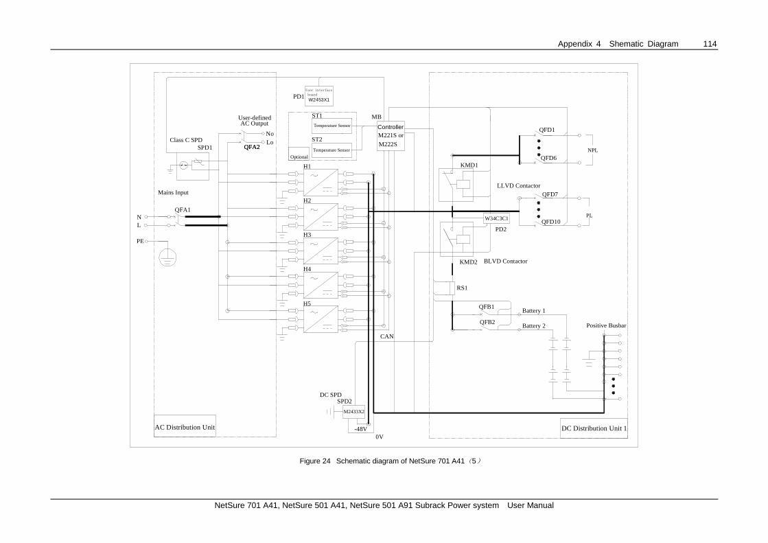
Appendix 4 Shematic Diagram 114
NetSure 701 A41, NetSure 501 A41, NetSure 501 A91 Subrack Power system User Manual
M2433X2
Battery 1QFB1
Battery 2QFB2
-48V0V
H1
CAN
RS1
QFD10PL
QFD7
DC Distribution Unit 1
Class C SPD
H2
H3
H4
KMD1
LLVD Contactor
NPL
QFD6
KMD2
L
W2453X1PD1
MB
Mains Input
QFA1
DC SPDSPD2
AC Distribution Unit
Positive Busbar
N
QFD1AC Output
User-defined
LoNo
PD2
BLVD Contactor
QFA2
W34C3C1
M221S or
M222SSPD1
H5
PE
Temperature Sensor
ST1
Temperature Sensor
ST2
Optional
QFA2
User interface
board
Controller
Figure 24 Schematic diagram of NetSure 701 A41(5)

Appendix 5 Glossary 115
NetSure 701 A41, NetSure 501 A41, NetSure 501 A91 Subrack Power system User Manual
Appendix 5 Glossary
Abbreviation Full word
Amb.Temp Ambient Temperature
Batt Battery
BC Boost Charging
BLVD Battery Lower Voltage Disconnection
Cap Capacity
CommMode Communication Mode
CurrLimit Current Limit
CycBC Cyclic Boost Charging
Con Alarm Voice Control Alarm Voice
Hist Alarm Historical alarm
HVSD High Voltage Shutdown
InitParam Initialize Parameters
InitPWD Initialize Password
LLVD Load Low Voltage Disconnection
LVD Low Voltage Disconnection
MCB Miniature Circuit Breaker
Ph-A Phase A
PWD Password
Rect Rectifier
Shunt coeff Shunt Coefficient
SM Supervision module (monitoring module)
SPD Surge Protection Device
SW Version Software Version
Sys System
Temp Temperature
Temp Comp Temperature Compensation
Volt Voltage