
User Maintenance Manual/Handbook - Isotech +44 (0)1704 543830 Fax: +44 (0) ... 3.5.1 Connecting...
61
User Maintenance Manual/Handbook Issue 1.01 Firmware version 1.00+ Isothermal Technology Limited, Pine Grove, Southport, PR9 9AG, England Isothermal Technology Limited, Pine Grove, Southport, PR9 9AG, England Isothermal Technology Limited, Pine Grove, Southport, PR9 9AG, England Isothermal Technology Limited, Pine Grove, Southport, PR9 9AG, England Tel: +44 (0)1704 543830 Fax: +44 (0)1704 544799 Internet: Tel: +44 (0)1704 543830 Fax: +44 (0)1704 544799 Internet: Tel: +44 (0)1704 543830 Fax: +44 (0)1704 544799 Internet: Tel: +44 (0)1704 543830 Fax: +44 (0)1704 544799 Internet: www.i www.i www.i www.isotech.co.uk sotech.co.uk sotech.co.uk sotech.co.uk E-mail: mail: mail: mail: [email protected] [email protected] [email protected] [email protected] The company is always willing to give technical advice and assistance where appropriate. Equally, because of the programme of continual development and improvement we reserve the right to amend or alter characteristics and design without prior notice. This publication is for information only.
-
Upload
hoangkhuong -
Category
Documents
-
view
223 -
download
4
Transcript of User Maintenance Manual/Handbook - Isotech +44 (0)1704 543830 Fax: +44 (0) ... 3.5.1 Connecting...

User Maintenance Manual/Handbook
Issue 1.01
Firmware version 1.00+
Isothermal Technology Limited, Pine Grove, Southport, PR9 9AG, EnglandIsothermal Technology Limited, Pine Grove, Southport, PR9 9AG, EnglandIsothermal Technology Limited, Pine Grove, Southport, PR9 9AG, EnglandIsothermal Technology Limited, Pine Grove, Southport, PR9 9AG, England
Tel: +44 (0)1704 543830 Fax: +44 (0)1704 544799 Internet: Tel: +44 (0)1704 543830 Fax: +44 (0)1704 544799 Internet: Tel: +44 (0)1704 543830 Fax: +44 (0)1704 544799 Internet: Tel: +44 (0)1704 543830 Fax: +44 (0)1704 544799 Internet: www.iwww.iwww.iwww.isotech.co.uksotech.co.uksotech.co.uksotech.co.uk EEEE----mail: mail: mail: mail: [email protected]@[email protected]@isotech.co.uk
The company is always willing to give technical advice and assistance where appropriate. Equally, because of the
programme of continual development and improvement we reserve the right to amend or alter characteristics and
design without prior notice. This publication is for information only.

©Isothermal Technology Page 2 of 61 914 millisKanner manual Iss. 1.00
CONTENTSCONTENTSCONTENTSCONTENTS
1111 INTRODUCTIONINTRODUCTIONINTRODUCTIONINTRODUCTION ............................................................................................................................................................. 4
1.1 UNPACKING ...................................................................................................................................................................... 5
1.2 SAFETY ............................................................................................................................................................................. 6
1.3 A QUICK TOUR OF YOUR MILLISKANNER .......................................................................................................................... 7
2222 USING YOUR MILLISKANUSING YOUR MILLISKANUSING YOUR MILLISKANUSING YOUR MILLISKANNERNERNERNER ..................................................................................................................................... 10
2.1 POWERING UP YOUR MILLISKANNER ............................................................................................................................... 10
2.2 CONNECTING A SINGLE MILLISKANNER TO A MILLIK ...................................................................................................... 12
2.3 CONNECTING MULTIPLE MILLISKANNERS TO A MILLIK .................................................................................................... 14
2.4 CONNECTING MILLISKANNERS TO OTHER INSTRUMENTS ................................................................................................ 16
2.5 CONTROLLING MILLISKANNER MANUALLY ...................................................................................................................... 19
3333 CONNECTING THERMOMETCONNECTING THERMOMETCONNECTING THERMOMETCONNECTING THERMOMETER SENSORSER SENSORSER SENSORSER SENSORS ................................................................................................................ 21
3.1 THE BINDING POSTS ....................................................................................................................................................... 21
3.2 CONNECTING PRTS (4-WIRE) ........................................................................................................................................ 21
3.3 CONNECTING PRTS (3-WIRE) ........................................................................................................................................ 21
3.4 CONNECTING PRTS (2-WIRE) ........................................................................................................................................ 22
3.5 CONNECTING THERMOCOUPLES ..................................................................................................................................... 24
3.5.1 Connecting Thermocouples (using an ice point) .................................................................................. 24
3.5.2 Connecting Thermocouples (using external compensation) ............................................................. 25
3.5.3 Connecting Thermocouples (using internal compensation) .............................................................. 26
3.6 CONNECTING THERMISTORS ........................................................................................................................................... 27
4444 GOOD PRACTICE GUIDELGOOD PRACTICE GUIDELGOOD PRACTICE GUIDELGOOD PRACTICE GUIDELININININESESESES ................................................................................................................................... 29
4.1 LOOKING AFTER YOUR MILLISKANNER ........................................................................................................................... 29
4.2 MAKING A GOOD ELECTRICAL MEASUREMENT ............................................................................................................... 29
5555 THE MILLISKANNER TECTHE MILLISKANNER TECTHE MILLISKANNER TECTHE MILLISKANNER TECHNOLOGYHNOLOGYHNOLOGYHNOLOGY .......................................................................................................................... 32
5.1 MINIMISING THERMAL EMFS .......................................................................................................................................... 32
5.2 SOLID-STATE SWITCHING .............................................................................................................................................. 33
6666 CALIBRATIONCALIBRATIONCALIBRATIONCALIBRATION ............................................................................................................................................................... 34
6.1 BEFORE YOU CHECK THE CALIBRATION .......................................................................................................................... 34
6.2 CHECKING THE REFERENCE JUNCTION SENSOR ............................................................................................................... 34
6.3 ADJUSTING THE REFERENCE JUNCTION SENSOR .............................................................................................................. 36
7777 UPDATING FIRMWAREUPDATING FIRMWAREUPDATING FIRMWAREUPDATING FIRMWARE ................................................................................................................................................ 38
8888 RSRSRSRS232 INTERFACE232 INTERFACE232 INTERFACE232 INTERFACE ....................................................................................................................................................... 41
8.1 ESTABLISHING AN RS232 CONNECTION ........................................................................................................................ 41
8.2 SCPI COMMAND SET...................................................................................................................................................... 44
8.2.1 SCPI Command Structure .............................................................................................................................. 45
8.2.2 SCPI Numeric Suffices .................................................................................................................................... 47

©Isothermal Technology Page 3 of 61 914 millisKanner manual Iss. 1.00
8.2.3 Parameters ........................................................................................................................................................ 47
8.2.4 Controlling the millisKanner Using the RS232 Port .............................................................................. 47
8.2.5 Terminology – Inputs and Channels ......................................................................................................... 48
8.2.6 SCPI Commands .............................................................................................................................................. 49
8.2.6.1 Command: REMote ........................................................................................................................................................ 50
8.2.6.2 Command: LOCal........................................................................................................................................................... 50
8.2.6.3 Command: *IDN? ........................................................................................................................................................... 50
8.2.6.4 Command: *RST ............................................................................................................................................................. 51
8.2.6.5 Command: [ROUTe:]CLOSe# ...................................................................................................................................... 51
8.2.6.6 Command: [ROUTe:]CLOSe? ....................................................................................................................................... 51
8.2.6.7 Command: [ROUTe:]OPEN[:ALL] ................................................................................................................................ 51
8.2.6.8 Command: MILLiskanner:LIST? .................................................................................................................................. 52
8.2.6.9 Command: MILLiskanner:INITialise .......................................................................................................................... 52
8.2.6.10 Command: MILLiskanner:STARt? ......................................................................................................................... 53
8.2.6.11 Command: MILLiskanner:CLOSe .......................................................................................................................... 53
8.2.6.12 Command: MILLiskanner:OPEN ............................................................................................................................ 53
8.2.6.13 Command: MILLiskanner:RJC:OFFSet#? ............................................................................................................. 54
8.2.6.14 Command: MILLiskanner:RJC:TEMPerature#? .................................................................................................. 54
8.2.6.15 Command: MILLiskanner:RST ............................................................................................................................... 54
8.2.6.16 Command: MEASure:RJC? ...................................................................................................................................... 54
8.2.6.17 Command: CALibrate:RJC:OFFSet ........................................................................................................................ 55
8.2.6.18 Command: CALibrate:RJC:OFFSet? ...................................................................................................................... 55
8.2.6.19 Command: CALibrate:PASSword .......................................................................................................................... 55
8.2.6.20 Command: CALibrate:UNLock .............................................................................................................................. 56
8.2.6.21 Command: CALibrate:LOCK .................................................................................................................................. 56
8.2.6.22 Command: FIRMware:LOADer .............................................................................................................................. 56
9999 SPECIFICATIOSPECIFICATIOSPECIFICATIOSPECIFICATIONNNN ............................................................................................................................................................ 58
10101010 APPROVALSAPPROVALSAPPROVALSAPPROVALS .................................................................................................................................................................. 59
10.1 CE DECLARATION ........................................................................................................................................................... 59
10.2 FCC STATEMENT ............................................................................................................................................................ 59
10.3 STANDARDS APPLIED ...................................................................................................................................................... 60
11 REVISION HISTORY .......................................................................................................................................................... 61

©Isothermal Technology Page 4 of 61 914 millisKanner manual Iss. 1.00
1111 IntroductionIntroductionIntroductionIntroduction
The millisKanner multiplexer can be connected to your milliK Precision Thermometer to
increase the number of input channels for any combination of PRT, thermocouple or
thermistor sensors. Each multiplexer has 8 input channels and up to 4 millisKanners can
be connected to a single milliK, providing you with up to 33 measurement channels. The
millisKanner includes features that enable you to make the most accurate measurements
possible with your milliK. When you connect the multiplexer to your milliK, the additional
channels appear automatically on your milliK and can be configured and used in exactly
the same way as the milliK’s own input channels, so you can get on with making
measurements rather than worrying about how to control your multiplexer.
Each channel is provided with 5 binding posts (for connection to a PRT or thermistor
sensor with bare-wire, 4mm plugs or spade connections) and a miniature thermocouple
connector. The output from the millisKanner is connected to Channel 2 of the milliK
(Channel 1 remains available). Each channel can be configured for use with PRTs,
thermocouples or thermistors giving you complete freedom when configuring your
system. Channel selection would normally be controlled by the milliK (via the RS232
interface), but manual control is also supported with the left/right buttons on the touch
panel.
The millisKanner uses the latest semiconductor technology to implement channel
switching rather than the mechanical relays that are commonly used in multiplexers. This
completely solid-state design makes the millisKanner highly reliable. The sense input
reversal (used to eliminate the effect of thermal EMFs on thermocouple measurements)
and internal reference junction sensor used in the milliK are reproduced in the

©Isothermal Technology Page 5 of 61 914 millisKanner manual Iss. 1.00
millisKanner. This means that measurements made using the millisKanner meet the same
uncertainty specification as those made with the milliK directly. The millisKanner does
not provide keep-warm currents, if this is required for a thermometer it should be
connected directly to the milliK.
This manual provides a comprehensive guide to using your millisKanner. We recognise
that you will probably not wish to read it through at this time so suggest you read the
safety section below, turn to Section 2.2 (to learn how to connect the millisKanner to
your milliK) and then refer back to the manual using the list of contents to find additional
information as required.
1.11.11.11.1 UnpackingUnpackingUnpackingUnpacking
Your millisKanner product should comprise the following items:
millisKanner multiplexer
a universal power supply with interchangeable plug heads
RS232 null modem cable
analogue link cable
this user manual
If you have ordered a millisKanner to add to an existing millisKanner system, the power
supply is replaced by a power lead and the analogue link cable is replaced by a
millisKanner-to-millisKanner link cable.
If any item is missing or damaged, please report this immediately to your supplier. If
possible, we recommend that you retain the packaging material in case you need to
return the instrument for calibration or service since it has been designed to ensure that
your millisKanner is properly protected during transportation.

©Isothermal Technology Page 6 of 61 914 millisKanner manual Iss. 1.00
!
1.21.21.21.2 SafetySafetySafetySafety
The millisKanner is a precision instrument, designed for use in a laboratory. It complies
with the requirements of safety standard EN61010-1 (2010) and is therefore safe to use
in laboratory or light industrial environments. It is not intended for use outdoors or in
extreme environments (refer to specification in Section 9).
The millisKanner is likely to be connected to thermometer sensors in use and the
operator should take care to ensure that the complete system is safe. For example, metal
sheathed thermometers may be connected to the millisKanner and then placed in a
furnace powered from a 230V electrical supply. Single fault conditions in such a furnace
could lead to the thermometer wires and therefore the binding posts and output
connectors of the millisKanner becoming electrically live and therefore a hazard to the
operator. Suitable precautions should be taken, such as using an isolating transformer in
the supply to such a furnace. If you require further advice on safety issues, please
contact Isothermal Technology or one of our appointed distributors - we have extensive
experience of thermometry and can provide advice and equipment to help you.
Retain these instructions. Use only as specified in these operating instructions or the
intrinsic protection may be impaired.
Please observe the following safety precautions:
Do not use your millisKanner if it is damaged
Connect only to a power supply with a voltage corresponding to that on the power
supply label (also given in the specification – see Section 9)
This equipment is for indoor use and will meet its performance figures within an
ambient temperature range of 5°C to 40°C with maximum relative humidity of 80%

©Isothermal Technology Page 7 of 61 914 millisKanner manual Iss. 1.00
for temperatures up to 31ºC decreasing linearly to 50% RH at 40ºC
Equipment is for operation at installation category II (transient voltages) and
pollution degree II in accordance with IEC 664 at altitudes up to 2000 metres
Always use the power supply supplied
This equipment is for use in moderate climates only. NEVER use the equipment in
damp or wet conditions
Avoid excessive heat, humidity, dust & vibration
Do not place liquid filled containers on the equipment
Do not use where the equipment (or any associated accessories) may be subjected
to dripping or splashing liquids
Ensure that the switch on the electrical supply outlet used is easily accessible to
allow the unit to be switched off
Ensure that tabletop equipment is placed on a solid, level surface, which is able to
support its weight (and that of any attached accessories)
Ensure all cables and wires are routed safely to avoid tripping: also to avoid sharp
bends and pinches
Clean only with a damp cloth. Do not wet or allow moisture to penetrate the unit.
Do not use solvents. See section 4.1 for details of cleaning procedure The product should be subjected to regular in-service inspections as required by
local regulations; a yearly interval is suggested
Do not apply earth test currents to any terminal/connector or to the shrouds of the
RS232 connectors
This equipment contains no user-serviceable parts. Refer all repairs to qualified
service personnel. Contact Isothermal Technology or one of our appointed
distributors for details of approved service outlets
1.31.31.31.3 A Quick Tour of Your millisKannerA Quick Tour of Your millisKannerA Quick Tour of Your millisKannerA Quick Tour of Your millisKanner
On the top panel of your millisKanner you will find the binding posts (five per channel)
and miniature thermocouple connectors for the eight inputs channels , the “left”/”right”
channel select buttons, the green “power” LED and eight red LEDs that indicate when a
channel is selected:

©Isothermal Technology Page 8 of 61 914 millisKanner manual Iss. 1.00
On the rear panel you will find the 5 output connectors (4mm sockets), two RS232 ports
and two DC power inlets (for 5V DC). Two RS232 and power inlets are provided in order
to allow millisKanners to be “daisy-chained” together. The unused RS232 port on the last
millisKanner in your system can be connected to a PC in order to control the whole
measurement system using your own software (see section 8). The command protocol
employs the widely used SCPI format (see section 8.2 for details).:
Left/Right Channel Select Buttons
Power LED
Binding Posts
Miniature
Thermocouple
Connectors
Channel LEDs
Output
Connectors (5 x 4mm Sockets)
2 x RS232
Ports
2 x DC
Power Inlets

©Isothermal Technology Page 9 of 61 914 millisKanner manual Iss. 1.00
The binding posts accept 4mm plugs, spades or bare wires. The current (I) and voltage
sense (V) terminals are spaced on 19mm (¾”) centres so that standard BNC to 4mm
adaptors (not supplied) can be used to connect to thermometer sensors that have BNC
terminations

©Isothermal Technology Page 10 of 61 914 millisKanner manual Iss. 1.00
!
2222 Using your millisKannerUsing your millisKannerUsing your millisKannerUsing your millisKanner
Your millisKanner is very easy to use, simply connect it to your milliK Precision
Thermometer (analogue and RS232 connections) and apply power to both instruments.
On power-up, the milliK ‘discovers’ any millisKanners connected to it and assigns
channel numbers to each input. These additional channels then appear in the list of
channels and can be configured and used in the same was as the existing channels on
the milliK.
The automatic discovery process takes place during initialisation of the milliK software
and requires the RS232 connection(s) to be present (see sections 2.2 or 2.3). If you
connect or power the millisKanner after the milliK software has initialised (at the initial
screen with the Start button, or later), press the Restart/Update Software button on the
Instrument screen of the milliK to re-invoke the discovery process.
A millisKanner will only work with a milliK that is running with firmware version 1.11 or
above and software version 1.5.4 or above. The firmware and software versions are
shown on the milliK in the opening screen (with the Start button). If your milliK is running
with older firmware or software, please contact Isothermal Technology or one of our
appointed distributors to arrange an upgrade. The hardware on all milliKs is compatible
with millisKanner multiplexers.
2.12.12.12.1 Powering Up Your millisKannerPowering Up Your millisKannerPowering Up Your millisKannerPowering Up Your millisKanner
The power supply operates from any standard AC electrical supply (90-264V RMS at 47-
63Hz), so unless your supply is unusual you can simply connect the power supply to a
suitable electrical outlet.

©Isothermal Technology Page 11 of 61 914 millisKanner manual Iss. 1.00
The power supply is fitted with a standard BS 1363 plug head but is provided with
alternative heads that cover the majority of electrical sockets used worldwide. If you need
to connect to an outlet socket that is not supported by the plug heads provided you
should source a suitable electrical supply lead locally that is fitted with a C8 connector,
you can then plug this directly into the C8 socket on the power supply. The plug head
can easily be changed:
Plug the DC connector from the power supply into either of the “DC Power” sockets on
the rear of the millisKanner.

©Isothermal Technology Page 12 of 61 914 millisKanner manual Iss. 1.00
2.22.22.22.2 Connecting a Single millisKanner to a milliKConnecting a Single millisKanner to a milliKConnecting a Single millisKanner to a milliKConnecting a Single millisKanner to a milliK
Using the null modem cable provided (see section 8.1 if you wish to make your own
cable), connect either of the RS232 ports on the millisKanner to either RS232 port on the
rear of the milliK (it does not matter which port is used as they are completely
interchangeable). Connect the five Output Terminals on the rear of the millisKanner to
Channel 2 of the milliK, using the link cable provided, carefully observing the colour
coding shown (note: the white wires must be connected to the V+/V- terminals):

©Isothermal Technology Page 13 of 61 914 millisKanner manual Iss. 1.00
Note the scanner output must be connected to Channel 2 of the milliKNote the scanner output must be connected to Channel 2 of the milliKNote the scanner output must be connected to Channel 2 of the milliKNote the scanner output must be connected to Channel 2 of the milliK
millisKanner millisKanner millisKanner millisKanner OutputOutputOutputOutput Plug ColourPlug ColourPlug ColourPlug Colour Wire ColourWire ColourWire ColourWire Colour
V- Black White
V+ Red White
I- Black Red
I+ Red Red
Green Green
N.B. You must use correct plug colour AND wire colour when making the connections.
If you wish to make your own interconnecting cable, use a screened cable with low
dielectric loss insulation such as PTFE or polyethylene (otherwise measurement
performance may be affected). The screen should be connected to the (green) ground
connector of the millisKanner and shell of the Lemo connector. The pin-out used for the
Lemo connectors (looking into the solder buckets) is:

©Isothermal Technology Page 14 of 61 914 millisKanner manual Iss. 1.00
4
5
6 1
2
I-
I+
V+V-
RESERVED
RESERVED
3
If the software on the milliK is already running, restart it by cycling the power or pressing
the Restart/Update Software button on the Instrument screen. This initiates the
automatic discovery process so that the milliK can detect any millisKanners connected to
it and assign channel numbers. The milliK will disable Channel 2, since it is always used
as the expansion channel input.
With a single millisKanner, the milliK assigns channel numbers 10 to 17 to the
multiplexer. The numbers (0 to 7) below each set of input terminals on the millisKanner
help to identify the terminals for each Channel (for example, the input marked as 4 is
Channel 14). The red LED (below the terminal posts) will light when measurements are
being made on that channel.
If you want to control the measurement system (milliK and millisKanner) from a PC,
connect the unused RS232 port on the millisKanner to a PC using a null modem cable.
You can still communicate with the milliK even though there is no physical connection to
it as the millisKanner will relay commands from the PC to the milliK and will relay back
responses from the milliK to the PC (see section 8 for further details).
2.32.32.32.3 Connecting Multiple millisKanners to a milliKConnecting Multiple millisKanners to a milliKConnecting Multiple millisKanners to a milliKConnecting Multiple millisKanners to a milliK
You may connect up to four millisKanners to a single milliK, giving a maximum of 33
input channels (channel 1 on the milliK and channels 10 to 17, 20 to 27, 30 to 37 and 40
to 47 via millisKanners). The first millisKanner in a system is supplied with an analogue

©Isothermal Technology Page 15 of 61 914 millisKanner manual Iss. 1.00
link cable terminated with a Lemo connector and a universal power supply. Additional
millisKanners are provided with analogue link cables terminated with stackable 4mm
plugs at both ends and a DC power link cable so that you can create the required
expanded system.
First connect a single millisKanner to your milliK (see section 2.2 above). Use the null
modem cable provided (see section 8.1 if you wish to make your own cable) to connect
the unused RS232 port on the rear of additional millisKanners to the unused RS232 port
on the previous millisKanner to form a ‘daisy-chain’ arrangement. The RS232 ports on
the millisKanner are completely interchangeable, so it does not matter which is used to
connect to the next millisKanner or the milliK in the system. Similarly, use the Power Link
cable provided to connect either DC Power connector on the millisKanner to the unused
DC Power connector on the previous millisKanner in a ‘daisy-chain’ arrangement.
Connect the five Output Terminals on the additional millisKanners (in parallel) to the first
millisKanner (the analogue cables provided use plugs that allow “piggy-back” connection
to make this easy):
If you wish to make your own analogue link cables, use a screened cable with low
dielectric loss insulation such as PTFE or polyethylene (otherwise measurement
performance may be affected). The screen should be connected to the ground terminals
on both millisKanners.

©Isothermal Technology Page 16 of 61 914 millisKanner manual Iss. 1.00
If the software on the milliK is already running, restart it by cycling the power or pressing
the Restart/Update Software button on the Instrument screen. This initiates the
automatic discovery process so that the milliK can detect any millisKanners connected to
it and assign channel numbers. The milliK will disable Channel 2, since it is always used
as the expansion channel input.
With multiple millisKanners, the milliK assigns channel numbers 10 to 17 to the
multiplexer connected directly to it. It then assigns channels numbers 20-27 to the next
multiplexer and so on. This means that the channel marked 7 on the third millisKanner in
the ‘daisy-chain’ of RS232 connections will be assigned channel number 37. The red LED
(below the binding posts) will light when measurements are being made on that channel.
If you want to control the measurement system (milliK and millisKanners) from a PC,
connect the unused RS232 port on the millisKanner at the end of the ‘daisy-chain’ to a
PC using a null modem cable. You can still communicate with the milliK even though
there is no physical connection to it as the millisKanners will relay commands from the
PC to the milliK and will relay back responses from the milliK to the PC (see section 8 for
further details).
2.42.42.42.4 Connecting Connecting Connecting Connecting millisKannermillisKannermillisKannermillisKanners tos tos tos to Other InstrumentsOther InstrumentsOther InstrumentsOther Instruments
Although the millisKanner has been designed specifically to work with the milliK
Precision Thermometer, it can be used with any other compatible instrument. The only
requirement for compatibility is that the instrument must be able to accommodate the
series resistance of the millisKanner, which is 5Ω (maximum) in series with each line. The
switching devices are rated at 0.5A and 60V (across open contacts), so should be
compatible with most thermometry instruments. The millisKanner is designed to switch

©Isothermal Technology Page 17 of 61 914 millisKanner manual Iss. 1.00
low-level signals, never use it to switch currents other than PRT/thermistor sense
currents or voltages above 60V.
The reference junction temperature is measured by a digital sensor and is only available
via the RS232 interface. If you wish to use internal reference junction compensation, you
will need to access the reference junction temperature via the RS232 interface using the
MEAS:RJC? command (see section 8.2.6.16) or the MILL:RJC:TEMP#? command (see
section 8.2.6.14).
Make up your own (screened) cable to connect the five output terminals on the rear of
the millisKanner to your instrument. Select channels using the RS232 interface (see
section 8) or manually (see section 2.5).
If you are controlling the millisKanner using the RS232 interface and making voltage
measurements (for thermocouples), make two measurements with opposite polarity
(using CLOS# POS and CLOS# NEG commands) and calculate half the (signed) difference
between the measurements in order to eliminate the effect of thermal EMFs generated in
the connection between the millisKanner and the instrument. This uses the internal sense
reversal feature of the millisKanner to make the highest accuracy voltage measurement.
If you do not use this feature, or are controlling the millisKanner manually (see section
2.5) you should use good quality, low thermal EMF connectors to connect between the
millisKanner and the instrument. The following Multi Contact 4mm stackable plugs are
recommended for the connection to the millisKanner:
Colour Multi Contact Part
Number
Farnell Stock Code
Black 22.2643-21 1085430
Red 22.2643-22 1085431
Green 22.2643-25 1085432

©Isothermal Technology Page 18 of 61 914 millisKanner manual Iss. 1.00
These readily available internationally from Farnell Electronics and can be ordered via
their website www.farnell.com
If a command is sent to the millisKanner to change channels, it returns a <CR> (carriage
return) when the change has been made. Any software you write should take advantage
of this feature and wait for the change to be acknowledged before making a
measurement as this will ensure that erroneous measurements are not made during a
transition.

©Isothermal Technology Page 19 of 61 914 millisKanner manual Iss. 1.00
2.52.52.52.5 ControllingControllingControllingControlling millisKannermillisKannermillisKannermillisKanner ManuallyManuallyManuallyManually
Control your millisKanner manually using the ‘Left’ and ‘Right’ buttons on the top panel:
The millisKanner starts up with no channel selected. Pressing the ‘Right’ button will then
select Channel 0. Press the ‘Right’ button when Channel 7 is selected or the ‘Left’ button
when Channel 0 is selected to turn off all channels. The ‘Channel LEDs’ indicate which
channel is selected.
When the millisKanner is connected to a milliK, the left/right buttons no longer operate
because the milliK sends the REM (see section 8.2.6.1) command to disable local control
of the millisKanner. To re-enable the left/right buttons, either send the LOC command
(see section 8.2.6.2) to the RS232 port or cycle the power to the instrument.
The millisKanner can be used manually with the milliK (do not connect it to the milliK
with the RS232 cable so that it is not detected by the milliK) or with another compatible
thermometer instrument. In both cases, the feature that reverses the sense connections
inside the millisKanner (to eliminate the effect of thermal EMFs generated in the wires
Left Button
Channel LEDs
Right Button

©Isothermal Technology Page 20 of 61 914 millisKanner manual Iss. 1.00
and connectors between the millisKanner and the instrument) does not operate. This
means that the voltage offset will be higher than when it is used with a milliK although it
should be well within the ±2µV specification of the milliK provided good quality (low
thermal EMF) connectors are used.

©Isothermal Technology Page 21 of 61 914 millisKanner manual Iss. 1.00
3333 Connecting Thermometer SensorsConnecting Thermometer SensorsConnecting Thermometer SensorsConnecting Thermometer Sensors
3.13.13.13.1 The Binding PostThe Binding PostThe Binding PostThe Binding Postssss
The binding posts accept 4mm plugs, bare wires or spade terminations. Additionally,
they are spaced on 19mm (¾”) pitch so that they can be used with standard 4mm-to-
BNC adaptors (not supplied) for connecting to BNC terminated PRTs.
3.23.23.23.2 Connecting PRTs (4Connecting PRTs (4Connecting PRTs (4Connecting PRTs (4----wire)wire)wire)wire)
Your millisKanner is optimised for high accuracy, 4-wire resistance measurement. The
PRT should be connected to the chosen input channel, as follows:
R
B
R
B
G
PRT/SPRT
+tc
RED
BLACK
RED
BLACK
GREEN
I
V
The top (green) terminal should be connected to the screen of the PRT’s lead (where
present) to minimise electrical noise picked up by the wires.
3.33.33.33.3 Connecting PRTs (3Connecting PRTs (3Connecting PRTs (3Connecting PRTs (3----wire)wire)wire)wire)
The millisKanner can be connected to 3-wire PRTs and will provide automatically
compensate for cable resistance. The two positive (red) terminals should be connected
together and the ‘single’ end of the 3-wire PRT should then be connected to the I+
terminal as follows:

©Isothermal Technology Page 22 of 61 914 millisKanner manual Iss. 1.00
R
B
R
B
G
3-WIRE PRT
+tc
RED
BLACK
RED
BLACK
GREEN
I
V
The connection between the positive (red) terminals should carry no current and should
be connected as close to the base of the I+ terminal as possible in order for the 3-wire
compensation to work effectively. The lowest 3-wire compensation error is achieved by
using a wire under the screw terminal to connect the positive terminal together and then
adding the 'single' PRT lead to the binding post:
The top (green) terminal should be connected to the screen of the PRT’s lead (where
present) to minimise electrical noise picked up by the wires. The thermometer type in the
setting screen must be set to “Default 3-Wire PRT” or a user-defined thermometer that
has been set to 3-wire in order for the 3-wire compensation to occur.
3.43.43.43.4 Connecting PRTs (2Connecting PRTs (2Connecting PRTs (2Connecting PRTs (2----wire)wire)wire)wire)
The millisKanner can be connected to 2-wire PRTs. The two red and two black
measurement terminals should be connected together and then connected to the PRT as
follows:

©Isothermal Technology Page 23 of 61 914 millisKanner manual Iss. 1.00
R
B
R
B
G
2-WIRE PRT
+tc
RED
BLACK
RED
BLACK
GREEN
I
V
The connections to the PRT should be short (low resistance) in order to minimise the
effect of lead resistance on the measurement. Alternatively, the connections can use
remote sensing (using the 4-wire measurement capability of the milliK) to eliminate the
effect of lead resistance completely. In this arrangement, the current and voltage sense
connections are kept separate and are only joined close to the PRT:
R
B
R
B
G
2-WIRE PRT
+tc
RED
BLACK
RED
BLACK
GREEN
I
V
The top (green) terminal should be connected to the screen of the PRT’s lead (where
present) to minimise electrical noise picked up by the wires.

©Isothermal Technology Page 24 of 61 914 millisKanner manual Iss. 1.00
3.53.53.53.5 Connecting Thermocouples Connecting Thermocouples Connecting Thermocouples Connecting Thermocouples
Connect thermocouples to your millisKanner by using miniature thermocouple plugs that
plug into the sockets below the binding posts for that channel. Copper miniature
thermocouple plugs should be used if you intend to use an ice point reference or
external reference junction compensation. If you intend to use internal reference junction
compensation, fit a plug of the same type as the thermocouple. As with all thermocouple
systems, the most accurate thermocouple measurements are made with an ice point and
the least accurate measurements are made with the internal reference junction
compensation.
If the thermocouple is provided with a screen (not common), it should be connected to
the top (green) binding post to minimise electrical noise picked up by the wires.
3.5.13.5.13.5.13.5.1 Connecting Thermocouples (using an ice pointConnecting Thermocouples (using an ice pointConnecting Thermocouples (using an ice pointConnecting Thermocouples (using an ice point))))
To use a thermocouple with an ice point (reference junction immersed in an ice point), fit
a copper miniature thermocouple connector to the thermocouple and connect this to the
socket below the binding posts. In the ‘Settings’ screen, set the Reference Junction to
“0°C”:

©Isothermal Technology Page 25 of 61 914 millisKanner manual Iss. 1.00
R
B
R
B
G
RED
BLACK
RED
BLACK
GREEN
I
V
- +Reference
Junction
Measurement
JunctionCu
Cu
M+
M-
Ice Point
3.5.23.5.23.5.23.5.2 Connecting Thermocouples (Connecting Thermocouples (Connecting Thermocouples (Connecting Thermocouples (using using using using external compensation)external compensation)external compensation)external compensation)
To use a thermocouple with external reference junction compensation (temperature of
reference junction measured using another channel), fit a copper thermocouple
connector to the thermocouple and connect this to the socket below the binding posts.
Another temperature sensor (PRT or thermistor) must be used to measure the reference
junction temperature (ensure that it is isothermal with the reference junction). Connect
this sensor to another channel (on the milliK or a millisKanner) and configure it with a
conversion to temperature units. If you do not first configure the channel so that it can
measure temperature, it cannot be used as the reference junction sensor. You cannot use
another thermocouple as the reference junction sensor as this could create circular
dependencies (also thermocouples are generally not sufficiently accurate). In the
‘Settings’ screen for the thermocouple channel, set the ‘Reference Junction’ to “External”
and select the appropriate channel for the reference junction temperature sensor:

©Isothermal Technology Page 26 of 61 914 millisKanner manual Iss. 1.00
R
B
R
B
G
- +Reference
Junction JunctionCu
Cu
M+
M-
Isothermal Environment
RED
BLACK
RED
BLACK
GREEN
I
V
R
B
R
B
G
+tc
This technique is less accurate than using an ice-point due to the additional
uncertainties associated with the PRT or thermistor used to monitor the reference
junction and any temperature gradients between the temperature of the PRT/thermistor
and the thermocouple’s reference junction.
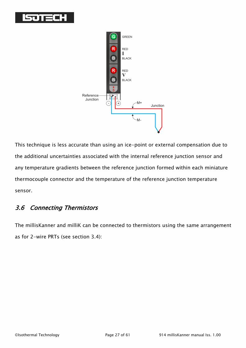
3.5.33.5.33.5.33.5.3 Connecting Thermocouples (Connecting Thermocouples (Connecting Thermocouples (Connecting Thermocouples (using using using using internal compensation)internal compensation)internal compensation)internal compensation)
To use a thermocouple with internal reference junction compensation (reference junction
formed within the millisKanner and its temperature measured using an internal sensor),
fit a thermocouple connector of the same type as the thermocouple and connect this to
the socket below the binding posts. In the ‘Settings’ screen for the thermocouple
channel, set the ‘Reference Junction’ to “Internal”:
©Isothermal Technology Page 27 of 61 914 millisKanner manual Iss. 1.00
R
B
R
B
G
RED
BLACK
RED
BLACK
GREEN
I
V
- + M+
M-
Junction
Reference
Junction
This technique is less accurate than using an ice-point or external compensation due to
the additional uncertainties associated with the internal reference junction sensor and
any temperature gradients between the reference junction formed within each miniature
thermocouple connector and the temperature of the reference junction temperature
sensor.
3.63.63.63.6 Connecting ThermistorsConnecting ThermistorsConnecting ThermistorsConnecting Thermistors
The millisKanner and milliK can be connected to thermistors using the same arrangement
as for 2-wire PRTs (see section 3.4):

©Isothermal Technology Page 28 of 61 914 millisKanner manual Iss. 1.00
R
B
R
B
G
THERMISTOR
+tc
RED
BLACK
RED
BLACK
GREEN
I
V
Because the resistance of thermistors used for temperature measurement is much higher
than for PRTs, lead resistance is not normally a problem.
The top terminal should be connected to the screen of the thermistor’s lead (where
present) to minimise electrical noise picked up by the wires. The high resistance of
thermistors makes them more prone to picking up electrical noise, it is therefore even
more important to use a screened cable and connect this to the screen terminal on the
millisKanner than when using PRTs.
©Isothermal Technology Page 29 of 61 914 millisKanner manual Iss. 1.00
4444 Good Practice GuidelinesGood Practice GuidelinesGood Practice GuidelinesGood Practice Guidelines
4.14.14.14.1 Looking After Your millisKannerLooking After Your millisKannerLooking After Your millisKannerLooking After Your millisKanner
Your millisKanner is a precision electronic instrument intended for indoor use in a
laboratory, light industrial or office environment. Nonetheless, it has been designed to be
as robust as practical and will provide many years of service, provided it is properly
maintained.
The only part of the millisKanner that requires a routine calibration check is the internal
reference junction temperature sensor. We recommend that you check this annually. You
can check this yourself using the procedures given in this manual (see section 6.2), or we
can provide a traceable calibration of your millisKanner at one of our approved
calibration centres (contact Isothermal Technology or one of our appointed distributors
for details). The millisKanner should require little maintenance between calibrations
other than routine cleaning.
Clean your millisKanner, as required, using either a proprietary cleaner (such as those
sold for cleaning PCs) or water and a little mild liquid soap on a lint-free cloth. Never use
abrasive cleaners (such as ‘cream’ cleaners) on your millisKanner.
4.24.24.24.2 Making a Good Electrical MeasurementMaking a Good Electrical MeasurementMaking a Good Electrical MeasurementMaking a Good Electrical Measurement
Although the millisKanner and milliK are intended for use in temperature metrology, its
base measurements are electrical (resistance or voltage). The limited sensitivity of PRTs
and thermocouples means that in order to achieve uncertainties at the mK level, we need
to make electrical measurements that rival those of a good electrical metrology
laboratory. For example, for a 25Ω SPRT a 5mK temperature uncertainty corresponds to

©Isothermal Technology Page 30 of 61 914 millisKanner manual Iss. 1.00
500\Ω resistance uncertainty. With a 1mA sense current, this corresponds to a voltage
uncertainty of 0.5\V.
The millisKanner and milliK are optimised for electromagnetic compatibility (minimising
emissions and maximising immunity). However, since the milliK is capable to measuring
to such low signal levels it is worthwhile adopting good electrical measurement practices.
Here are a few guidelines:
The most sensitive points are the inputs to the millisKanner or milliK (measuring to
better than 0.5\V). Whilst the millisKanner and milliK will work satisfactorily with
just a four-wire connection to the PRT or thermistor, it is better to use a screened
cable and to connect the screen to the measurement ground terminal above the
input terminals:
R
B
R
B
G
RED
BLACK
RED
BLACK
GREEN
I
V
Screened Cable
The screen should also be connected to the outer sheath of the PRT (if it is metal
clad). The use of screened cables is more important when the milliK is used with
thermistors, which have a higher resistance than PRTs or thermocouples.
Keep the cables to the millisKanner and milliK input terminals away from other
cables that might be sources of electrical noise (for example electrical supplies to
furnaces).
The insulation in high temperature furnaces (any that ‘glow’) begins to conduct at
higher temperatures. This can cause high common-mode voltages on any

©Isothermal Technology Page 31 of 61 914 millisKanner manual Iss. 1.00
thermometer in the furnace. Whilst the milliK is designed to reject common-mode
DC and AC signals (at both 50 and 60Hz), it is good practice to minimise them. It
is common practice to use a metal equalising block in a furnace when performing
comparison calibrations. This should be connected to the safety earth of the
electrical supply (most furnaces designed for temperature metrology applications
are fitted with a device to ‘earth’ the equalising block). Do not ‘earth’ the
equalising block to the screen/measurement ground terminals on the front panel
of your millisKanner or milliK as this is not connected to the safety earth of the
electrical supply.
Provide a ‘clean’ electrical environment in your temperature laboratory. It may be
useful to filter your electrical supply into the laboratory especially if other heavy
electrical machinery is being used nearby on the same supply (the milliK has very
good immunity to electrical noise conducted along the electrical supply, but other
equipment in your laboratory may be more sensitive). It is worth avoiding the use
of sources of electrical signals or noise in your laboratory. Examples include
furnaces with triac controls (especially those that ‘chop’ the electrical supply part
way through a cycle – better controllers switch only at the zero-crossing point to
‘chop’ only whole cycles), mobile phones (the millisKanner and milliK are not
significantly affected by mobile phones, but other equipment may be more
sensitive).

©Isothermal Technology Page 32 of 61 914 millisKanner manual Iss. 1.00
5555 The millisKanner TechnologyThe millisKanner TechnologyThe millisKanner TechnologyThe millisKanner Technology
The millisKanner uses a number of new technologies and measurement techniques to
achieve performance and ease of use that have not previously been available with similar
multiplexers.
5.15.15.15.1 Minimising Thermal EMFsMinimising Thermal EMFsMinimising Thermal EMFsMinimising Thermal EMFs
Thermal EMFs (EMFs generated when circuits comprising dissimilar metals are exposed
to temperature gradients) are a potential source of error when working at this precision.
These can be eliminated when measuring resistance thermometers by reversing the
current and averaging the measurements (the offsets in the two measurements cancel
each other out when the readings are averaged together). However, this technique cannot
be used when measuring the voltage generated by thermocouples, so the thermal EMFs
need to be eliminated at source. For this reason, we use tellurium-copper (gold plated)
as the thermocouple connector contact material, since this combines good mechanical
properties with extremely low thermal EMFs against the copper terminations of a
thermocouple.
In order to eliminate thermal EMFs from the measurement system (already small), the
input connections are reversed between the input and output terminals of the
millisKanner. Measurements made with and without the reversal are then averaged
together to eliminate the thermal EMFs generated in the connectors and cables used to
connect the millisKanner to the milliK. The limitation is then the thermal EMFs generated
by the devices used to implement this reversal.
The millisKanner duplicates the reversal system used by the milliK. It detects that it is
making a measurement via a millisKanner, and then makes the reversal in the

©Isothermal Technology Page 33 of 61 914 millisKanner manual Iss. 1.00
millisKanner rather than the milliK. This means that the voltage measurement uncertainty
is the same whether measurements are made directly on the milliK or via a millisKanner.
5.25.25.25.2 SolidSolidSolidSolid----State SwitchingState SwitchingState SwitchingState Switching
One of the most common sources of failure in instruments of this complexity is the
contacts in switches, relays, connectors and potentiometers. For this reason, the
millisKanner was designed to have no switches, mechanical relays, internal connectors or
potentiometers in order to ensure optimum reliability.
Conventional instruments of this type use mechanical relays for some or all of the signal
routing. The millisKanner uses only solid-state switching. The thermal EMFs from these
solid-state devices are significantly less than even the best mechanical relays. As a
result, the millisKanner achieves voltage offsets significantly less than 2\V.

©Isothermal Technology Page 34 of 61 914 millisKanner manual Iss. 1.00
6666 CalibrationCalibrationCalibrationCalibration
The only part of the millisKanner that requires routine calibration is the reference
junction temperature sensor. There is a single sensor for all the channels. The software
in the milliK that is used to check and adjust its reference junction temperature sensor
can also be used to check and adjust the calibration of the reference junction sensor in
any attached millisKanner.
The millisKanner uses a high quality semiconductor sensor to measure the reference
junction temperature in order to ensure good long-term stability. We recommend that
you check its calibration annually using the procedures given below. Alternatively, we can
provide a traceable calibration of your millisKanner at one of our approved calibration
centres (contact Isothermal Technology or one of our appointed distributors for details).
6.16.16.16.1 Before You Check the CalibrationBefore You Check the CalibrationBefore You Check the CalibrationBefore You Check the Calibration
Any calibration should be performed in a temperature controlled environment between
19°C and 25°C. The millisKanner should be powered up and left to stabilise in the
calibration environment for at least 2 hours before checking or adjusting calibration.
6.26.26.26.2 Checking the Reference Junction SensorChecking the Reference Junction SensorChecking the Reference Junction SensorChecking the Reference Junction Sensor
Check the accuracy of the internal reference junction compensation (RJC) system by
connecting a thermocouple to any of the millisKanner channels and measuring a known
temperature using internal RJC mode. Any discrepancy between the measured and known
temperature indicates an error in the RJC system (or the thermocouple used). You can
use any thermocouple type for the measurement, but we recommend type J
thermocouples as these have high sensitivity near room temperature and are readily
available (the thermocouple needs to be fitted with a type J miniature thermocouple
plug).

©Isothermal Technology Page 35 of 61 914 millisKanner manual Iss. 1.00
Connect the thermocouple to the millisKanner (channel 10 in the example below) and set
the milliK to read °C for that channel with internal RJC by changing the parameters in the
‘Settings’ screen:
Press the NumericNumericNumericNumeric (F2) key, clear the statistics and wait for 100 measurements to be
made (when the display shows “Mean of 100”). The mean value indicated by the milliK
should be compared with the known temperature. Any discrepancy may be the result of
errors in the RJC system or the thermocouple used. You might consider using an ice bath
for the “known” temperature, and this is a reasonable choice. However, the error on a
type J thermocouple, even at 20°C might be 5\V (or even higher), which corresponds to a
temperature error of approximately 0.2°C. An alternative approach would be to use room
temperature as the “known” temperature and to measure this with a calibrated PRT
connected to the milliK. This approach has the advantage that the difference between
room temperature and the reference junction in the millisKanner is likely to be very small
(< 3°C) so any error resulting from imperfections in the thermocouple will also be small.
You need to ensure that the thermocouple is at the same temperature as the PRT. You
can create an adequate isothermal environment using a stainless steel vacuum flask filled
with silicone oil (or another suitable liquid) and agitated with a small air pump of the type

©Isothermal Technology Page 36 of 61 914 millisKanner manual Iss. 1.00
designed to aerate fish tanks. Clip the thermocouple to the PRT such that the junction is
near to the sensing element in the PRT (perhaps 1-2cm from the end) with nylon cable
ties and immerse the assembly in the oil.
There is only one reference junction sensor for all the channels, so you can use any
millisKanner channel for this check.
6.36.36.36.3 Adjusting the Adjusting the Adjusting the Adjusting the Reference Junction SensorReference Junction SensorReference Junction SensorReference Junction Sensor
You can adjust the calibration of the millisKanner using the RJC Sensor Calibration
feature in the milliK to which it is attached. Before you can use this feature you must first
attach a calibrated thermocouple to one of the channels and configure the channel for
use with this thermometer (see milliK manual for details). If you measure the ambient
temperature with a calibrated PRT and use this as the “known” temperature for the
calibration, you can use a good quality, uncalibrated thermocouple since the difference
between ambient temperature and the reference junction will be very small, so any error
will be insignificant. If you use an uncalibrated thermocouple, make sure that you set the
thermocouple ‘Conversion’ to the thermocouple type used:
From the ‘Calibration Menu’ Window, use the ↑↑↑↑ ↓↓↓↓ keys to select ‘RJ Sensor’ and then
press the ↵↵↵↵ key to proceed to the ‘RJ Sensor Calibration Adjustment’ screen. Use the ←←←←

©Isothermal Technology Page 37 of 61 914 millisKanner manual Iss. 1.00
→→→→ keys to select the relevant channel and then use the ↑↑↑↑ ↓↓↓↓ keys to select each parameter
in turn and press the ↵↵↵↵ key to enter their values:
Press the OKOKOKOK (F4) key to start the calibration adjustment. Once started, the calibration
adjustment process cannot be aborted.

©Isothermal Technology Page 38 of 61 914 millisKanner manual Iss. 1.00
7777 UpdaUpdaUpdaUpdating Firmwareting Firmwareting Firmwareting Firmware
Update the firmware in your millisKanner by sending the FIRMware:LOADer command to
an RS232 port (to set the millisKanner into programming mode) and then sending the
new firmware (in Intel HEX format). The FIRM:LOAD command can be used to update the
firmware or roll back to an earlier version. Once the FIRM:LOAD command has been
invoked, the millisKanner will not return to normal operation until the firmware has been
updated successfully.
Connect the millisKanner to your PC using a null-modem RS232 cable (see section 8.1).
Use Hyperterminal (or another terminal emulator) to connect to your millisKanner.
Hyperterminal is part of the standard Windows installation, usually located in the
Accessories|Communications folder. If you have installed a minimum (laptop) or custom
configuration (without this component) in your Windows operating system, you may need
to install Hyperterminal from your original Windows media.
Start Hyperterminal to setup a new connection. Type in a name for the connection (such
as millisKanner) and select an icon. In the next window, select the PC’s COM port to
which you have connected your millisKanner from the Connect using drop-down list and
click OK. In the next window, enter the data format for the millisKanner’s RS232
interface:

©Isothermal Technology Page 39 of 61 914 millisKanner manual Iss. 1.00
Click OK to open a Hyperterminal session with the millisKanner. Type *IDN? into
Hyperterminal (terminate the command by pressing the carriage return or Enter keys),
the millisKanner should then respond with a string in the form:
Isothermal Technology, millisKanner,13-P525, 1.00
This confirms that you have successfully established an RS232 connection with your
millisKanner. The last parameter reported is the current firmware version (in this case,
1.00) so you can ensure that you wish to change this for the version you are about to
install.
Send FIRM:LOAD 1234 (if password is still default value) to put the millisKanner into
programming mode. The millisKanner will report “Switched to Bootloader mode”, Now
select “Send Text File…” from the “Transfer” drop-down menu. In the Window that opens,
change “Files of type:” to “All files (*.*)” otherwise the required file will not be visible.
Navigate to the new firmware file, which will have a filename similar to
“millisKanner_1_00.hex” and then click ‘Open’. Hyperterminal will then send the new
firmware file to the millisKanner, which will show progress by returning decimal points:
©Isothermal Technology Page 40 of 61 914 millisKanner manual Iss. 1.00
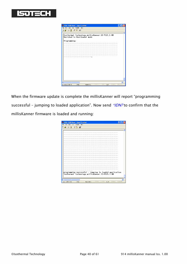
When the firmware update is complete the millisKanner will report “programming
successful – jumping to loaded application”. Now send *IDN? to confirm that the
millisKanner firmware is loaded and running:

©Isothermal Technology Page 41 of 61 914 millisKanner manual Iss. 1.00
8888 RS232 InterfaceRS232 InterfaceRS232 InterfaceRS232 Interface
The millisKanner is configured and controlled through its RS232 interface(s). It is
equipped with two RS232 interfaces so that a number of millisKanners can be controlled
by a single milliK precision thermometer (or other measuring instrument) by ‘daisy-
chaining’ them together with RS232 null-modem cables. The millisKanner responds
identically to data received on the two RS232 ports so they are completely
interchangeable. Even in a system in which a number of millisKanners are daisy-chained
together, the cables to the two RS232 ports may be reversed without any impact on the
operation of the system.
8.18.18.18.1 Establishing an RS23Establishing an RS23Establishing an RS23Establishing an RS232 Connection2 Connection2 Connection2 Connection
The RS232 connectors are located on the rear of your millisKanner (see section 1.3). The
connector is a 9-way (male) D-type configured as a standard DTE device:
PinPinPinPin NameNameNameName FunctionFunctionFunctionFunction
1 CD carrier detect (not connected)
2 RD receive data
3 TD transmit data
4 DTR data terminal ready (connected to pin 6:
DSR)
5 SG signal ground
6 DSR data set ready (connected to pin 4: DTR)
7 RTS request to send (connected to pin 8: CTS)
8 CTS clear to send (connected to pin 7: RTS)
9 - not used (not connected)
Shell FG frame ground (screen)
Connect your millisKanner to the milliK, other millisKanners or a PC using a standard
null-modem cable:

©Isothermal Technology Page 42 of 61 914 millisKanner manual Iss. 1.00
1
2
3
4
5
6
7
8
9
Shell
1
2
3
4
5
6
7
8
Shell
9
Null-Modem Cable
A screened RS232 cable is recommended for minimum emissions.

©Isothermal Technology Page 43 of 61 914 millisKanner manual Iss. 1.00
The format for the RS232 interface is as follows:
Baud
Rate
9,600
Start Bits 1
Stop Bits 1
Parity Bit none
The millisKanner has a 255-byte circular receive buffer. If the buffer becomes full and
the data continues to be sent data this will be ignored (lost) until the millisKanner has
had time to make space in the buffer by processing commands. The millisKanner returns
a <CR> (carriage return) to indicate completion of all commands that changes its state.
The milliK uses this feature to handshake with any connected millisKanners and so will
never over-run the buffer.
Although the millisKanner is intended to be connected to and controlled by a milliK
Precision Thermometer, you can control it from a PC using your own software or
Hyperterminal (or another terminal emulator) via the RS232 connection. Hyperterminal is
part of the standard Windows installation, usually located in the
Accessories|Communications folder. If you have installed a minimum (laptop) or custom
configuration (without this component) for your Windows operating system, you may
need to install Hyperterminal from your original Windows media.
Start Hyperterminal to setup a new connection. Type in a name for the connection (such
as millisKanner) and select an icon. In the next window, select the PC’s COM port to
which you have connected your millisKanner from the Connect using drop-down list and
click OK. In the next window, enter the data format for the millisKanner’s RS232
interface:

©Isothermal Technology Page 44 of 61 914 millisKanner manual Iss. 1.00
Click OK to open a Hyperterminal session with the millisKanner. Now save (using
File|Save As) the Hyperterminal connection so that in future you only have to click on this
icon to open an RS232 connection with your millisKanner.
Type *IDN? into Hyperterminal (terminate the command by pressing the carriage return
or Enter keys), the millisKanner should then respond with a string in the form:
Isothermal Technology, millisKanner,13-P525, 1.00
This confirms that you have successfully established an RS232 connection with your
millisKanner.
8.28.28.28.2 SCPI Command SetSCPI Command SetSCPI Command SetSCPI Command Set
The command format and protocol used by the millisKanner is based on the SCPI
(Standard Commands for Programmable Instruments) standard. This was developed to
provide a consistent command language for all types of programmable instruments. The
objective was to reduce the development time required by users of these instruments by
providing a consistent programming environment through the use of defined messages,
instrument responses and data formats. Further information on SCPI can be obtained
from the SCPI Consortium (http://www.scpiconsortium.org).
©Isothermal Technology Page 45 of 61 914 millisKanner manual Iss. 1.00
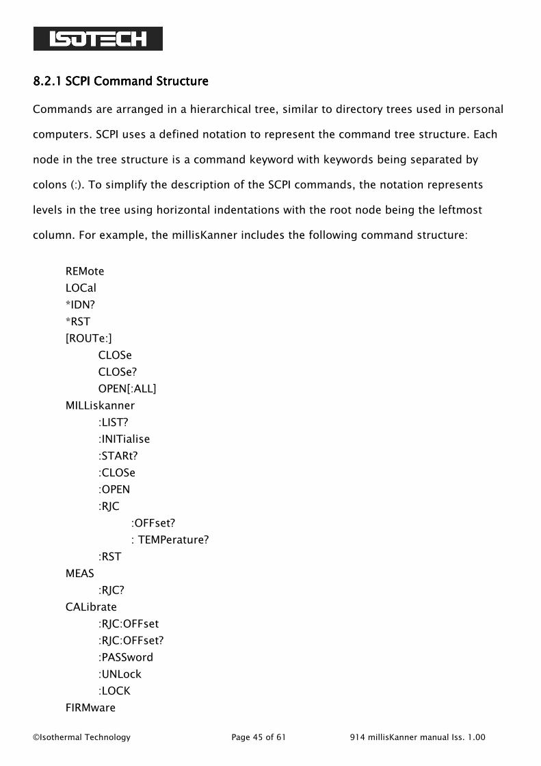
8.2.18.2.18.2.18.2.1 SCPI Command StructureSCPI Command StructureSCPI Command StructureSCPI Command Structure
Commands are arranged in a hierarchical tree, similar to directory trees used in personal
computers. SCPI uses a defined notation to represent the command tree structure. Each
node in the tree structure is a command keyword with keywords being separated by
colons (:). To simplify the description of the SCPI commands, the notation represents
levels in the tree using horizontal indentations with the root node being the leftmost
column. For example, the millisKanner includes the following command structure:
REMote
LOCal
*IDN?
*RST
[ROUTe:]
CLOSe
CLOSe?
OPEN[:ALL]
MILLiskanner
:LIST?
:INITialise
:STARt?
:CLOSe
:OPEN
:RJC
:OFFset?
: TEMPerature?
:RST
MEAS
:RJC?
CALibrate
:RJC:OFFset
:RJC:OFFset?
:PASSword
:UNLock
:LOCK
FIRMware

©Isothermal Technology Page 46 of 61 914 millisKanner manual Iss. 1.00
:LOADer
A valid command is formed by following the tree structure from a root node until a node
is reached with no further nodes below it, for example in the above command tree we
may use:
MILLiskaner:RJC:TEMPerature?
Keywords can be shortened to the first four letters (or 3 if the last letter is a vowel). To
indicate this, the notation uses upper-case to indicate required letters and lower-case to
indicate optional letters (NB: all commands are case-insensitive). For example, valid
forms of the above command include:
milliskanner:rjc:temperature?
mill:rjc:temp?
MILL:RJC:TEMP?
Mill:Rjc:Temperature?
To shorten the commands, default (optional) keywords are enclosed in square brackets
and may be omitted. For example, in the case of the command:
[ROUTe:]OPEN[:ALL]
Valid forms of this command include:
Route:Open:all
ROUT:OPEN:ALL
open

©Isothermal Technology Page 47 of 61 914 millisKanner manual Iss. 1.00
8.2.28.2.28.2.28.2.2 SCPI Numeric SufficesSCPI Numeric SufficesSCPI Numeric SufficesSCPI Numeric Suffices
In order to support multiple input channels, commands can include numeric suffices.
These are represented by a hash (#) in the command notation, for example:
[ROUTe:]CLOSe#
In order to close input 3, the command used would be:
CLOS3
8.2.38.2.38.2.38.2.3 ParametersParametersParametersParameters
If a command requires parameter(s), these follow the command and are separated from it
by a space. If more than one parameter is required, each parameter is separated by a
comma (,). For example, the command to change the password is:
CALibrate:PASSword <old password>,< password>,<password>
8.2.48.2.48.2.48.2.4 ControllingControllingControllingControlling the mithe mithe mithe millillillillisKanner Using the RS232 PortsKanner Using the RS232 PortsKanner Using the RS232 PortsKanner Using the RS232 Port
The millisKanner has two RS232 ports so that up to four millisKanners can be ‘daisy-
chained’ onto the RS232 port of a milliK. The SCPI commands for the milliK and
millisKanner have been designed to allow commands and data to be passed along the
daisy-chain. Each device in the daisy-chain responds to commands that it recognises as
being intended for it and passes any other commands or data on. During initialisation
(after power is applied), the milliK assigns channel numbers to each millisKanner in the
daisy chain (channels 10-17 for the first millisKanner, channel 20-27 for the second
etc.).
The millisKanners are all controlled by the milliK during a measurement so it is not
necessary for the user to control any of the millisKanners explicitly when making

©Isothermal Technology Page 48 of 61 914 millisKanner manual Iss. 1.00
measurements via the RS232 port. The millisKanner’s unused RS232 port at the opposite
end of the daisy chain to the milliK can be connected to a PC. The same commands used
to make measurements with the milliK can be used to make measurement via the
millisKanner channels. These are passed forward by each millisKanner until they reach
the milliK. The milliK then issues the required commands to the millisKanners in order to
select the specified channel and synchronises this with the measurements. Any
responses from the milliK are passed back to the PC via the millisKanners.
For example, consider a milliK with two millisKanners attached. The PC is connected to
the RS232 port on the second millisKanner, which will automatically be assigned channel
numbers 20-27 by the milliK. To measure the resistance of a 4-wire PRT connected to
the first input on the second millisKanner (channel 20) on the 125Ω range at normal
current (1mA), the user can simply send the command:
MEAS:RES20? 125,NORM,4
This is identical to the command required to read directly from channel 1 of the milliK
(see milliK manual) but with the channel number specified as 20 rather than 1.
8.2.58.2.58.2.58.2.5 Terminology Terminology Terminology Terminology –––– Inputs and ChannelsInputs and ChannelsInputs and ChannelsInputs and Channels
The terminals on a millisKanner are referred to as “Inputs” and are numbered 0 to 7 on
each multiplexer. When connected to a milliK, these inputs are allocated a unique
channel numbers so that they can be referenced/addressed by the milliK. The terms
“Input” and “Channel” are used in this manual to distinguish between the physical input
to the multiplexer and the number used to address the input channel.
The channel numbers are assigned by the milliK to each millisKanner in blocks of 8
aligned to the nearest decade value. The first millisKanner connected to the milliK is

©Isothermal Technology Page 49 of 61 914 millisKanner manual Iss. 1.00
assigned channel numbers 10 to 17. Subsequent millisKanners are assigned channel
numbers 20-27 etc.
8.2.68.2.68.2.68.2.6 SCPI CommandsSCPI CommandsSCPI CommandsSCPI Commands
The millisKanner supports the following commands:
REMote
LOCal
*IDN?
*RST
[ROUTe:]
CLOSe#
CLOSe?
OPEN[:ALL]
MILLiskanner
:LIST?
:INITialise
:STARt?
:CLOSe#
:OPEN#
:RJC
:OFFset#?
: TEMPerature#?
:RST
MEAS
:RJC?
CALibrate
:RJC:OFFset
:RJC:OFFset?
:PASSword
:UNLock
:LOCK
FIRMware
:LOADer
A detailed description of each command follows:
©Isothermal Technology Page 50 of 61 914 millisKanner manual Iss. 1.00
8.2.6.18.2.6.18.2.6.18.2.6.1 ComComComCommand: REMotemand: REMotemand: REMotemand: REMote
Format: REMote
Sets the millisKanner for remote (RS232) control only and disables local controls
(left/right buttons). The millisKanner always starts in local mode.
Example: to prevent the user from controlling the millisKanner using the left/right
buttons, send REM.
8.2.6.28.2.6.28.2.6.28.2.6.2 Command: LOCalCommand: LOCalCommand: LOCalCommand: LOCal
Format: LOCal
Re-enables local controls (left/right buttons). The millisKanner always starts in local
mode (as if LOC had been sent).
Example: to re-enable the left/right buttons (after they have been disabled by sending
REM), send LOC.
8.2.6.38.2.6.38.2.6.38.2.6.3 Command: *IDN?Command: *IDN?Command: *IDN?Command: *IDN?
Format: *IDN?
Reports information on the millisKanner in 4 comma separated fields:
manufacturer
model
serial number
firmware version
Example: for a millisKanner with serial number 13-P525 using firmware version 1.00, the
millisKanner responds to *IDN? with:
©Isothermal Technology Page 51 of 61 914 millisKanner manual Iss. 1.00
Isothermal Technology,millisKanner,13-P525,1.00
8.2.6.48.2.6.48.2.6.48.2.6.4 Command: *RSTCommand: *RSTCommand: *RSTCommand: *RST
Format: *RST
Performs a reset (equivalent to a power-on reset) of the millisKanner.
8.2.6.58.2.6.58.2.6.58.2.6.5 Command: [ROUTe:]CLOSeCommand: [ROUTe:]CLOSeCommand: [ROUTe:]CLOSeCommand: [ROUTe:]CLOSe####
Format: [ROUTe:]CLOSe<input#> POSitive|NEGative
Selects (connects input to output) the specified input (on the millisKanner to which the
RS232 connection is made). The polarity of the sense terminals is defined by the
POSitive|NEGative parameter. The millisKanner returns a <CR> (carriage return) to
acknowledge that the channel has been selected and is ready to use.
Example: to select the first millisKanner input with normal (positive) polarity, use:
CLOSE0 POS
8.2.6.68.2.6.68.2.6.68.2.6.6 Command: [ROUTe:]CLOSe?Command: [ROUTe:]CLOSe?Command: [ROUTe:]CLOSe?Command: [ROUTe:]CLOSe?
Format: [ROUTe:]CLOSe?
Reports the connection status (which channels are selected and their settings) on the
millisKanner to which the RS232 connection is made.
Example: a milliKanner with channel 3 selected for normal polarity (positive) will respond
to CLOS? with “3,positive”. If no inputs are selected, the response is “0,open”
8.2.6.78.2.6.78.2.6.78.2.6.7 Command: [ROUTe:]OPEN[:ALL]Command: [ROUTe:]OPEN[:ALL]Command: [ROUTe:]OPEN[:ALL]Command: [ROUTe:]OPEN[:ALL]
Format: [ROUTe:]OPEN[:ALL]

©Isothermal Technology Page 52 of 61 914 millisKanner manual Iss. 1.00
Deselects (disconnects) all inputs (on the millisKanner to which the RS232 connection is
made).
Example: to deselect all inputs use: OPEN
8.2.6.88.2.6.88.2.6.88.2.6.8 Command: MICommand: MICommand: MICommand: MILLiLLiLLiLLiskanner:LIST?skanner:LIST?skanner:LIST?skanner:LIST?
Format: MILLiskanner:LIST?
This command is used by the milliK to ‘discover’ which millisKanners are connected in
the ‘daisy-chain’. It reports information on the millisKanner and also forwards the
command to the next millisKanner in the daisy chain (on the alternate RS232 port) so
that it will also respond.
Example: if there are two millisKanners (serial numbers 13-P543 and 13-P544, firmware
1.00) connected in the daisy chain with a milliK (serial number 13-P432, firmware 2.00)
at the other end of the chain, the response to MILL:LIST? will be:
Isothermal Technology,millisKanner,13-P543,1.00
Isothermal Technology,millisKanner,13-P544,1.00
Isothermal Technology,milliK,13-P432,2.00
8.2.6.98.2.6.98.2.6.98.2.6.9 Command: MICommand: MICommand: MICommand: MILLiLLiLLiLLiskanner:INITialiseskanner:INITialiseskanner:INITialiseskanner:INITialise
Format: MILLiskanner:INITialise <start>
This command is reserved for use by the milliK and should not be used directly. It is used
to assign channel numbers to each millisKanner in the daisy-chain. It assigns channel
number <start> to the first input and sends the same command with <start>
incremented by 10 to the next millisKanner in the daisy-chain (on the alternate RS232
port).

©Isothermal Technology Page 53 of 61 914 millisKanner manual Iss. 1.00
Example: after discovering whether there are any millisKanners attached at power-up,
the milliK will send the command MILL:INIT 10 to start numbering input channels on the
millisKanners from channel 10 upwards.
8.2.6.108.2.6.108.2.6.108.2.6.10 Command: MICommand: MICommand: MICommand: MILLiLLiLLiLLiskanner:STARt?skanner:STARt?skanner:STARt?skanner:STARt?
Format: MILLiskanner:STARt?
Reports the channel number of the first input (on the millisKanner to which the RS232
connection is made).
Example: in a system with two millisKanners connected to a milliK, the response to the
command MILLI:START? sent to the second (last) millisKanner in the daisy-chain is “20”.
8.2.6.118.2.6.118.2.6.118.2.6.11 Command: MICommand: MICommand: MICommand: MILLiLLiLLiLLiskanner:CLOSeskanner:CLOSeskanner:CLOSeskanner:CLOSe
Format: MILLiskanner:CLOSe<channel#> POSitive|NEGative
This command is reserved for use by the milliK and should not be used directly. It is used
to select (connect input to output) the specified channel in the daisy-chain. All other
channels are automatically deselected. The polarity of the sense terminals is defined by
the POSitive|NEGative parameter. The millisKanner returns a <CR> (carriage return) to
acknowledge that the channel has been selected and is ready to use.
Example: to select channel 17 with normal (positive) polarity, use: MILL:CLOS17 POS
8.2.6.128.2.6.128.2.6.128.2.6.12 Command: MICommand: MICommand: MICommand: MILLiLLiLLiLLiskanner:OPENskanner:OPENskanner:OPENskanner:OPEN
Format: MILLiskanner:OPEN<channel#>
This command is reserved for use by the milliK and should not be used directly. It is used
to deselect (disconnect) the specified channel in the daisy-chain.
©Isothermal Technology Page 54 of 61 914 millisKanner manual Iss. 1.00
Example: to deselect channel 17, use: MICR:OPEN17
8.2.6.138.2.6.138.2.6.138.2.6.13 Command: MICommand: MICommand: MICommand: MILLiLLiLLiLLiskanner:skanner:skanner:skanner:RJC:RJC:RJC:RJC:OFFSetOFFSetOFFSetOFFSet####????
Format: MILLiskanner:RJC:OFFSet<channel#>?
Reports the calibrated RJC sensor offset (in °C) for the specified channel.
Example: a millisKanner (assigned channel numbers 20-29) with an RJC sensor offset of
0.123°C will respond to MILL:RJC:OFFS25? with “0.123”.
8.2.6.148.2.6.148.2.6.148.2.6.14 Command: MILLiskanneCommand: MILLiskanneCommand: MILLiskanneCommand: MILLiskanner:RJC:Tr:RJC:Tr:RJC:Tr:RJC:TEMPEMPEMPEMPerature#?erature#?erature#?erature#?
Format: MILLiskanner:RJC:TEMPerature<channel#>?
Reports the temperature of the reference junction (in °C) for the specified channel.
Example: a millisKanner (assigned channel numbers 20-29) with a reference junction
temperature of 20.123°C will respond to MILL:RJC:TEMP25? with “20.123”.
8.2.6.158.2.6.158.2.6.158.2.6.15 Command: MICommand: MICommand: MICommand: MILLiLLiLLiLLiskanner:RSTskanner:RSTskanner:RSTskanner:RST
Format: Command: MILLiskanner:RST
This command is reserved for use by the milliK and should not be used directly. It is
used to reset all the millisKanners in the daisy-chain by performing a reset (equivalent to
a power-on reset) and passing the command to the next millisKanner in the daisy-chain.
Example: on power-up a milliK will send the command MILL:RST to reset all the
millisKanners connected to its RS232 port.
8.2.6.168.2.6.168.2.6.168.2.6.16 Command: Command: Command: Command: MEAMEAMEAMEASureSureSureSure::::RJC?RJC?RJC?RJC?
Format: MEASure:RJC?

©Isothermal Technology Page 55 of 61 914 millisKanner manual Iss. 1.00
Reports the temperature of the reference junction (on the millisKanner to which the
RS232 connection is made).
Example: a millisKanner with a reference junction temperature of 20.123°C will respond
to MEAS:RJC? with “20.123”.
8.2.6.178.2.6.178.2.6.178.2.6.17 Command: CALibrate:Command: CALibrate:Command: CALibrate:Command: CALibrate:RJC:RJC:RJC:RJC:OFFSetOFFSetOFFSetOFFSet
Format: CALibrate:RJC:OFFSet
Sets the value of the offset applied to the RJC sensor (on the millisKanner to which the
RS232 connection is made). The value is in °C and has a range of ±10°C. This command
will only work if the calibration has first been unlocked using the CAL:UNL command (see
section 8.2.6.20).
Example: to set an offset that will be added to the RJC temperature sensor on the
millisKanner to 0.321°C (password still set to default value) use: CAL:UNL 1234 followed
by CAL:RJC:OFFS 0.321
8.2.6.188.2.6.188.2.6.188.2.6.18 Command: CALibrate:Command: CALibrate:Command: CALibrate:Command: CALibrate:RJC:RJC:RJC:RJC:OFFSet?OFFSet?OFFSet?OFFSet?
Format: CALibrate:RJC:OFFSet?
Reports the offset added to measurements made by the reference junction sensor (on the
millisKanner to which the RS232 connection is made).
Example: a milliK that has been calibrated to have a 0.321°C offset added to reference
junction sensor measurements will respond to CAL:RJC:OFFS? with “0.321”.
8.2.6.198.2.6.198.2.6.198.2.6.19 Command: CALibrate:PASSwordCommand: CALibrate:PASSwordCommand: CALibrate:PASSwordCommand: CALibrate:PASSword
Format: CALibrate:PASSword <old password>,<password>,<password>

©Isothermal Technology Page 56 of 61 914 millisKanner manual Iss. 1.00
Changes the password used to lock (protect) the calibration of the millisKanner. This is
initially set to “1234”, but should be changed before using the millisKanner for any
critical or traceable measurement or calibration work. The new password must be at least
4 characters in length and must be typed in identically twice in order to effect the
change.
Example: to change the password from 1234 to ABCD use: CAL:PASS 1234,ABCD,ABCD
8.2.6.208.2.6.208.2.6.208.2.6.20 Command: CALibrate:UNLockCommand: CALibrate:UNLockCommand: CALibrate:UNLockCommand: CALibrate:UNLock
Format: CALibrate:UNLock <password>
Unlocks the millisKanner to allow calibration adjustment. The millisKanner always powers
up in the locked state. Calibration can be re-locked by cycling the power or using
CAL:LOCK (see section 8.2.6.21).
Example: to unlock (enable) the calibration adjustment on a millisKanner with the default
password (“1234”), use: CAL:UNL 1234
8.2.6.218.2.6.218.2.6.218.2.6.21 Command: CCommand: CCommand: CCommand: CALALALALibrate:LOCKibrate:LOCKibrate:LOCKibrate:LOCK
Format: Calibrate: LOCK
Locks the millisKanner to prevent calibration adjustment.
Example: to lock the calibration of a millisKanner after adjustment, use: CAL:LOCK
8.2.6.228.2.6.228.2.6.228.2.6.22 Command: FIRMware:LOADerCommand: FIRMware:LOADerCommand: FIRMware:LOADerCommand: FIRMware:LOADer
Format: FIRMware: LOADer <password>
Puts the millisKanner into a special mode that allows the firmware to be updated by
subsequently sending the new file in Intel HEX format (see section 7).

©Isothermal Technology Page 57 of 61 914 millisKanner manual Iss. 1.00
Example: to put the millisKanner (which still has the default password “1234”) into the
mode that allows the firmware to be updated, use: FIRM:LOAD 1234

©Isothermal Technology Page 58 of 61 914 millisKanner manual Iss. 1.00
9999 SpecificationSpecificationSpecificationSpecification
AccuracyAccuracyAccuracyAccuracy Same as milliK used (the millisKanner contributes no
additional measurement uncertainty – see section 5)
Input ChannelsInput ChannelsInput ChannelsInput Channels 8
Input/OutputInput/OutputInput/OutputInput/Output
ConnectorsConnectorsConnectorsConnectors
Binding Posts for: 4mm plugs, spades or bare wires
Miniature thermocouple connectors (contact material:
gold plated tellurium copper)
InterfacesInterfacesInterfacesInterfaces 2 x RS232 (9,600 baud)
OperatingOperatingOperatingOperating
ConditionsConditionsConditionsConditions
15-30°C / 50-85°F, 10-90% RH (for full specification)
0-40°C / 32-105°F, 0-95% RH (operational)
PowerPowerPowerPower 90 – 264V (RMS), 47-63Hz (universal)
1.5W maximum
SizeSizeSizeSize 255mm x 255mm x 80mm / 10.0” x 10.0” x 3.2” (W x
D x H)
WeightWeightWeightWeight 2.3kg / 5lb

©Isothermal Technology Page 59 of 61 914 millisKanner manual Iss. 1.00
10101010 ApprovalsApprovalsApprovalsApprovals
The millisKanner has been independently verified as complying with the regulatory
requirements of the EU and FCC for electromagnetic compatibility and safety (EU only).
10.110.110.110.1 CE DeclarationCE DeclarationCE DeclarationCE Declaration
European Community Electromagnetic Compatibility Directive (89/336)European Community Electromagnetic Compatibility Directive (89/336)European Community Electromagnetic Compatibility Directive (89/336)European Community Electromagnetic Compatibility Directive (89/336)
European Community Low Voltage Directive (93/68)European Community Low Voltage Directive (93/68)European Community Low Voltage Directive (93/68)European Community Low Voltage Directive (93/68)
The millisKanner multiplexer manufactured by Isothermal Technology Limited of Pine
Grove, Southport, Merseyside, PR9 9AG, United Kingdom conforms to the requirements
of the European Community Electromagnetic Compatibility Directive (89/336) and of the
European Community Low Voltage Directive (93/68).
10.210.210.210.2 FCC StatementFCC StatementFCC StatementFCC Statement
This equipment has been tested and found to comply with the limits for a Class A digital
device, pursuant to part 15 of the FCC Rules. These limits are designed to provide
reasonable protection against harmful interference when the equipment is operated in a
commercial environment. This equipment generates and can radiate radio frequency
energy and, if not installed and used in accordance with the instruction manual, may
cause harmful interference to radio communications. Operation of this equipment in a
residential area may cause harmful interference, in which case the user will be required
to correct the interference at their own expense. Changes or modifications to this
equipment not expressly approved by Isothermal Technology could degrade EMC
performance and void the user’s authority to operate the equipment.

©Isothermal Technology Page 60 of 61 914 millisKanner manual Iss. 1.00
10.310.310.310.3 Standards AppliedStandards AppliedStandards AppliedStandards Applied
The following standards have been applied in assessing compatibility with the
requirements for CE marking and for FCC compliance:
Conducted Emissions EN61326:2006 & CFR47:2012
Radiated Emissions EN61326:2006 & CFR47:2012
Conducted Immunity EN61326:2006
Radiated Immunity EN61326:2006
Electrical Fast Transients EN61326:2006
Electrostatic Discharge EN61326:2006
Surge EN61326:2006
Voltage Dips & Interruptions EN61326:2006
Harmonic Currents EN61000-3-2:2006
Flicker EN61000-3-3:2008
Electrical Safety EN61010-1:2010

©Isothermal Technology Page 61 of 61 914 millisKanner manual Iss. 1.00
11 Revision History
Change Note Date Manual Issue
Initial release 28/02/2013 1.00
CN13105 17/07/2013 1.01


![Finale 2004 - [Showtime I - Fullscore Harmonie.MUS]£ ã ã bb bb bb # # # # b b bb bb bb bb bb bb 44 44 44 44 44 44 44 44 44 44 44 44 44 44 44 44 44 44 44 44 44 44 4 4 4 4 4 4 4 4](https://static.fdocuments.net/doc/165x107/5b08e3307f8b9a520e8d5803/finale-2004-showtime-i-fullscore-bb-bb-bb-b-b-bb-bb-bb-bb-bb-bb-44.jpg)


