USER GUIDE: THREMAL WELDING - ccinfra.se · MADE IN UK 1712.01.EN USER GUIDE: THREMAL WELDING 2009...
6
MADE IN UK 1712.01.EN USER GUIDE: THERMAL WELDING www.concretecanvas.com 2009 Winner Material Connexion Medium Award Material of the Year Winner D&AD Yellow Pencil Award Product Design 2012 R&D 100 Award winner R&D Magazine 2013 Innovation Award Winner Railtex Exhibition 2014 Queen’s Award for Enterprise in Innovation 2014 Fast Track 100 16th fastest growing company in the UK. Innovation Award ICE Wales Cymru Awards 2017 Winner Technical Innovation Award 2013 Macrobert Award Finalist
Transcript of USER GUIDE: THREMAL WELDING - ccinfra.se · MADE IN UK 1712.01.EN USER GUIDE: THREMAL WELDING 2009...

MADE IN UK
1712.01.EN
USER GUIDE:THERMAL WELDING
www.concretecanvas.com
2009 WinnerMaterial Connexion Medium Award
Material of the YearWinner
D&AD Yellow Pencil Award
Product Design
2012 R&D 100Award winner
R&D Magazine
2013 Innovation Award WinnerRailtex Exhibition
2014 Queen’s Award for Enterprise in
Innovation
2014 Fast Track 100 16th fastest growing company in the UK.
Innovation AwardICE Wales Cymru Awards 2017
WinnerTechnical Innovation Award
2013Macrobert Award
Finalist
© Concrete Canvas Ltd. 2017The information contained herein is off ered free of charge and is, to the best of our knowledge, accurate. However, since the circumstances and conditions in which such information and the products discussed therein can be used may vary and are beyond our control, we make no warranty, express or implied, of merchantability, fi tness or otherwise, or against patent infringement, and we accept no liability, with respect to or arising from use of such information or any such product. Patent and Trademark information can be found here: http://www.concretecanvas.com/patent-and-trademark-info/
[email protected]+44 (0) 345 680 1908 www
CC HydroTM GCCB Thermal Welding
Material
Equipment
1.0 Installation
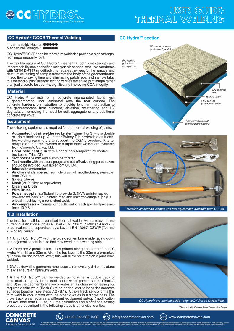
CC HydroTM section
Modified air channel clamps and test equipment, available from CC Ltd
Impermeability Rating : ●●●●●Mechanical Strength : ●●●●●CC HydroTM GCCB* can be thermally welded to provide a high strength, high impermeability joint. The flexible nature of CC HydroTM means that both joint strength and impermeability can be verified using an air-channel test. In accordance with ASTM D-7177 (modified) this negates the need for the removal and destructive testing of sample tabs from the body of the geomembrane. In addition to saving time and eliminating patch repairs of sample tabs, this method of joint strength testing verifies the entire joint length rather than just discrete test points, significantly improving CQA integrity.
CC Hydro™ consists of a concrete impregnated fabric with a geomembrane liner laminated onto the rear surface. The concrete hardens on hydration to provide long term protection to the geomembrane from puncture, abrasion, weathering and UV degradation removing the need for soil, aggregate or any additional concrete top cover.
The following equipment is required for the thermal welding of joints:
The installer shall be a qualified thermal welder with a relevant and current qualification such as a Level 2 EN 13067: CSWIP (7.4 and 7.5) or equivalent and supervised by a Level 1 EN 13067: CSWIP (7.4 and 7.5) or equivalent.
1.1 Unroll CC Hydro™ with the blue geomembrane side facing down and adjacent sheets laid so that they overlap the welding strip.
1.2 There are 2 parallel black lines printed along one edge of the CC Hydro™ at 15 and 30mm. Align the top layer to the 30mm pre-marked guideline on the bottom layer; this will allow for a testable joint once welded.
1.3 Wipe down the geomembrane faces to remove any dirt or moisture; this will ensure an optimum weld.
1.4 The CC Hydro™ can be welded using either a double track or triple track set-up. A double track set-up welds parallel seams (Track A and B) in the geomembrane and creates an air channel for testing but requires a third weld (Track C) to be added later to bond the concrete surfaces together (see steps 7.2 - 8.1). A triple track set-up forms this third weld in conjunction with the other 2 welds in a single pass. The triple track weld requires a different equipment set-up (modification kits available from CC Ltd) but the calibration and air-channel testing procedure described in the following steps is otherwise identical. *Geosynthetic Cementitious Composite Barrier
• Automated hot air welder (eg Leister Twinny T or S) with a double or triple track set-up. A Leister Twinny T is preferable as it can log welding parameters to support the CQA procedure. Kits to adapt a double track welder to a triple track welder are available from Concrete Canvas Ltd.
• Hand-held heat gun with closed loop temperature control (eg Leister Triac AT)• Slot nozzle 20mm and 40mm perforated• Test needle with pressure gauge and cut-off valve (triggered valves should be avoided) Available from CC Ltd.• Infrared thermometer• Air channel clamps such as mole grips with modified jaws, available from CC Ltd.• Safety gloves• Mask (A2P3 filter or equivalent)• Cleaning Cloth• Wire Brush• Power supply (sufficient to provide 2.3kVA uninterrupted power to welder). An uninterrupted and uniform voltage supply is critical in achieving a consistent weld.• Air compressor or manual pump sufficient to reach specified pressures (max 10.9 Bar)
CC HydroTM pre-marked guide - align to 2nd line as shown here
Pre-markedguide linesfor alignment

© Concrete Canvas Ltd. 2017The information contained herein is off ered free of charge and is, to the best of our knowledge, accurate. However, since the circumstances and conditions in which such information and the products discussed therein can be used may vary and are beyond our control, we make no warranty, express or implied, of merchantability, fi tness or otherwise, or against patent infringement, and we accept no liability, with respect to or arising from use of such information or any such product. Patent and Trademark information can be found here: http://www.concretecanvas.com/patent-and-trademark-info/
[email protected]+44 (0) 345 680 1908 www
Double Track Weld
Triple Track Weld
2.0 Trial Welds
3.0 Air-channel Testing
2.1 Always complete a trial weld before commencement of field welding to ensure the machine is setup correctly and producing adequate welds. Trial welds should be conducted as a minimum at the start of each day and preferably after every 4 hours of operation or following any period of machine shut down, change of operator or change in ambient conditions and conducted in accordance with TWI guidance.
2.2 Follow the welding equipment manufacturers’ recommendations on machine set-up (may vary depending on ambient temperature and humidity); generally for good quality welds, the speed setting should be <1.5m/min, temperature >550°C and the pinch pressure P>600N. NOTE: Over tightening of the pinch rollers may result in ‘splaying’ of the weld. 2.3 Weld a minimum length of 1m and conduct pressure testing as described in ‘Air-channel Testing’. If the trial weld does not pass the air channel test, repeat the weld at higher temperature or lower speed and re-test. If burning is visible on the PVC, reduce the heat or increase the speed then repeat the trial weld and re-test.
3.1 Air-channel testing is the recommended method of performing non-destructive testing to verify the strength and impermeability, of a thermally welded joint. The following test methods are in accordance with ASTM D-7177 (modified) and will effectively test the joint strength substantially in excess of 2.6 kN/m (15lb/in) width minimum peel strength. The testing procedure and parameters used should be project specific and specified by the project engineer in agreement with the client. The procedures and parameters given here are for guidance only.
Weld TrackA
Weld TrackB
CC Hydro 5mm laidwith fibrous
surface uppermost
CC Hydro 5mm laidwith fibrous top
surface uppermost
Air channel forQC pressure
testing
16mm 16mm
16mm
1.2mm
Min 5mm
Weld Track A Weld Track B
Weld Track C CC Hydro 5mm laidwith fibrous
surface uppermost
CC Hydro 5mm laidwith fibrous top
surface uppermost
Air channel forQC pressure
testing
10mm
10mm
Min 5mm
10mm
1.2mm
A Twinny T in use
Seal end of the continuous air channel with a clamp

© Concrete Canvas Ltd. 2017The information contained herein is off ered free of charge and is, to the best of our knowledge, accurate. However, since the circumstances and conditions in which such information and the products discussed therein can be used may vary and are beyond our control, we make no warranty, express or implied, of merchantability, fi tness or otherwise, or against patent infringement, and we accept no liability, with respect to or arising from use of such information or any such product. Patent and Trademark information can be found here: http://www.concretecanvas.com/patent-and-trademark-info/
[email protected]+44 (0) 345 680 1908 www
3.0 Air-channel Testing continued...3.2 Allow the weld to cool to within 10oC of the ambient temperature.Record the ambient sheet temperature using a laser/infra-red thermometer.
3.3 Make a slit at least 100mm from the edge at both ends of the weld and outside the containment zone and insert the test needle at one end and apply the sealing clamp. A small amount of grease will help to achieve a seal pressurise the air channel to the pressure appropriate for the sheet temperature (see Table 1 below). Apply a flat clamp to the slit at the other end.
3.4 Air channel testing for CC Hydro™ is a 2-stage process:
Stage 1: Peel Strength Test• Maintain the minimum pressure (Table 1) from the source for a
minimum of 30 seconds.• Inspect the joint along its length from the end opposite the needle
for complete inflation. If the joint completely inflates and there is no audible or visible evidence of air leakage, the joint passes the test.
• A failure of the channel to pressurise indicates a leak (provided that air is not leaking from the test needle or clamps) - see Corrective Action. If the channel passes, progress to Stage 2.
Stage 2: Impermeability Test• At the specified pressure (Table 1), close off the air supply and monitor the pressure for a further 30 seconds. If the pressure drop is less than
10% of the test pressure, the joint passes the test. It is critical to ensure air is not leaking from the clamps.
3.5 At completion of the test, open the air channel at the end opposite the test needle. Air should rush out and the pressure gauge should register an immediate drop in pressure, indicating that the entire length of the seam has been tested (if not, there is a blockage in the joint).
3.6 It is suggested to mark both ends of the joint with the inspector’s initials, joint identification letter or numbers, or both, length inspected, date, sheet temperature and test pressure.
3.7 As a minimum, the following information should be recorded for each weld and retained by the supervisor:• Identify the specific weld and the date of welding• Welder Make/Model and operating settings used: Pressure (N), Temperature (oC) and Speed (m/min)• Operators’ names• Sheet Temperature, Air Pressure and Hold Time of test• If the test was a Pass/Fail/Repair and details of repair.
3.8 In the case of a failure inspect the joint from the end furthest from the needle and locate the leak point (normally detectable by sound or puff of dust). Another technique to locate a leak is to have an additional clamp and at 3m increments, clamp off the channel to locate the air leak.
CC HydroTM Air-channel testing
TT (Double Track) TTT (Triple Track)Sheet
Temperature (°C)
SheetTemperature
(°F)
Air Pressure (kPa)
Air Pressure (psi)
Air Pressure (bar)
Air Pressure (kPa)
Air Pressure (psi)
Air Pressure (bar)
Hold Time (seconds)
5 41 683 99 6.8 1090 158 10.9 30s
10 50 656 95 6.6 1023 148 10.2 30s
15 59 628 91 6.3 956 139 9.6 30s
20 68 600 87 6.0 889 129 8.9 30s
25 77 572 83 5.7 822 119 8.2 30s
30 86 544 79 5.4 755 109 7.5 30s
35 95 517 75 5.2 688 100 6.9 30s
40 104 489 71 4.9 620 90 6.2 30s
45 113 461 67 4.6 553 80 5.5 30s
50 122 433 63 4.3 486 71 4.9 30s

Repairs to Weld Track B can made by accessing the weld from the top
© Concrete Canvas Ltd. 2017The information contained herein is off ered free of charge and is, to the best of our knowledge, accurate. However, since the circumstances and conditions in which such information and the products discussed therein can be used may vary and are beyond our control, we make no warranty, express or implied, of merchantability, fi tness or otherwise, or against patent infringement, and we accept no liability, with respect to or arising from use of such information or any such product. Patent and Trademark information can be found here: http://www.concretecanvas.com/patent-and-trademark-info/
[email protected]+44 (0) 345 680 1908 www
5.0 Repair Procedure
6.0 Welding Cut Edges
5.1 Weld Track A. Access to the geomembrane should be made by flipping the CC Hydro™ so that rear blue geomembrane face is exposed. If possible the faulted area should be re-welded using the 5mm or 20mm slot nozzle. If this is not possible, the area will need to be patch repaired, by cutting back to remove all imperfections and overlaying with a single piece of compatible geomembrane to give a minimum overlap of 100mm in all directions from the failure point. The patch material should have rounded corners and be bonded onto the surface of the geomembrane using the hand held heat gun and slot nozzle. This method can also be used to repair damage to the body of the geomembrane.Concrete Canvas Ltd can supply additional rolls of blue geomembrane for patching purposes.5.2 Weld Track B. Repairs to Weld Track B can made by accessing the weld from the top face of the material (fibrous side). If a triple track weld has been used, the concrete overlap (Weld Track C) will need to be carefully cut open to provide access to Weld Track B.The nozzle of the hand-held heat gun should be inserted between the concrete overlap of the affected area and the damaged weld carefully re-welded. A 5mm or 20mm nozzle should be selected depending on size of the repair to be made.A steel plate or steel rule can be used to prevent damage to the surface fibres from the hot metal parts of the thermal welder when completing this repair.
6.1 It may be necessary to weld cut edges of CC Hydro™, such as when creating pie joints, or when welding the ends of a roll where there is no welding strip. For these situations, Concrete Canvas Ltd can supply blue geomembrane in 200mm wide strips which can be welded, using the standard method described above, onto the edge to be jointed. The CC Hydro™ can then be thermally welded as normal.
4.0 Corrective Action4.1 Air Channel Blockage - Clamp at the blockage and test in both directions. Due to the flexibility of the geomembrane used in CC Hydro™, inflation of the air channel up to the blockage is easily visible. Therefore releasing the air pressure at the testing device is acceptable in this situation.
4.2 Weld - When a weld failure is detected the joint should be retested on both sides of the failure. If the two parts pass, then repair the weld failure point as described below.
Repair to Weld Track A
A steel rule can be used to prevent damage to the fibrous surface
Weld Track C would need to be opened carefully to access Weld Track B
Welding on a 200mm strip

© Concrete Canvas Ltd. 2017The information contained herein is off ered free of charge and is, to the best of our knowledge, accurate. However, since the circumstances and conditions in which such information and the products discussed therein can be used may vary and are beyond our control, we make no warranty, express or implied, of merchantability, fi tness or otherwise, or against patent infringement, and we accept no liability, with respect to or arising from use of such information or any such product. Patent and Trademark information can be found here: http://www.concretecanvas.com/patent-and-trademark-info/
[email protected]+44 (0) 345 680 1908 www
7.0 Creating the 3rd weld (Track C) using a hand-held heat gun
8.0 Other Useful Guidance
7.1 If a double weld set-up has been used to create the thermal welded joints, then it is necessary to bond the concrete surfaces together using a hand-held heat gun. This 3rd weld (Weld Track C) is important as it creates a continuous concrete protection layer over the geomembrane and prevents debris and sunlight entering the joint and potentially damaging the liner.
7.2 This 3rd weld should be applied after the double weld has been completed but must be done prior to hydration. A hand-held heat gun with closed loop temperature feedback and fitted with a perforated slot nozzle should be used. Additionally, a rubber coated roller may be used as a means of applying pressure to the joint immediately after welding.
7.3 Position the welding nozzle just inside the joint, with the nozzle perforations upper-most, directing the hot air onto the blue geomembrane. Working your way from one end of the joint to the other, follow the welder with the roller to apply pressure to the softened PVC and top fibres to form a bond. Weld rate is approximately 1m/min. Leave the welded joint to cool for approximately 5 minutes prior to applying any load.
7.4 As with the standard weld, a trial weld should be conducted prior to commencement of a field weld in order to set weld temperature and speed. A successful joint is indicted by a film tear bond failure when destructively tested in peel.
8.1 When deploying the CC Hydro™, care should be taken not to over tension the product during the laying process as this may create stretch marks or wrinkles.
8.2 Routine maintenance of the welding equipment is required and particular attention should be paid to the hot air nozzle which should be regularly cleaned with a wire brush to prevent the build-up of PVC residue.
8.3 On uneven ground, sandbags may be used to ensure joints are in contact with the substrate and prevent voids beneath the CC Hydro™.
8.4 For complex areas and junctions, the geomembrane can be jointed using a hand-held welder or using a PVC solvent. It is recommended to form ‘boots’ for pipe penetrations on site using a hand-held heat gun and slot nozzle.
8.5 Concrete grout can be used in tandem with thermal welding to aid with jointing around upstands or other infrastructure.
8.6 For detailed guidance on mechanical attachment of CC Hydro™ to penetrations and structures refer to ASTM D-6497.
8.7 On large projects, it is recommended to cover the last strip of un-hydrated CC Hydro™ at the end of the day (eg. with a plastic tarpaulin) to protect it from moisture or rainfall which may cause partial hardening and impinge on the next phase of welding work.
8.8 Personnel should wear dry, non-damaging shoes. Trafficking of un-hydrated CC Hydro™ should be kept to a minimum. It should not be trafficked while setting.
8.9 Do not allow heavy vehicular traffic directly on CC Hydro™ unless the subgrade has been prepared with sufficient surface modulus to support vehicle traffic without causing rutting. In which case rubber-tired ATV’s and trucks are acceptable on unset CC Hydro™ if wheel contact is less than 55 kPa.
8.10 A stiff brush can be used to clean the surface of CC Hydro™ prior to hydration in order to remove footprints, dust accumulation and prevent staining on the set material.
8.11 When powering down the automatic or manual thermal welders it is recommended to turn off the heating element whilst allowing the air to remain running in order to cool the element and avoid damage.
8.12 This guide is intended to provide an overview of thermal welding of CC Hydro™, however, it is not exhaustive and is intended for guidance purposes only. It is always recommended that installation is carried out by a fully trained and qualified thermal welding technician (eg. a level 1 to EN 13067: CSWIP 7.4 and 7.5 or equivalent with a minimum of 2 years geomembrane welding experience).
A trial weld should be conducted prior to commencement of a field weld
A Hand-held heat gun with 40mm slot nozzle & a 45mm seam roller
Wear heavy gloves and a mask (A2P3 filter or equivalent) as the Geomembrane will be hot and will give off fumes. Only thermally weld CC HydroTM in a well ventilated area. See CC Equipment List for full details. Dust hazard. Wear appropriate PPE. Consult CC SDS document.