
User Guide SM-Universal Encoder Plus - PS Log · The SM-Universal Encoder Plus option module allows...
70
www.controltechniques.com User Guide SM-Universal Encoder Plus Solutions module for Unidrive SP Part Number: 0471-0005 Issue Number: 1
Transcript of User Guide SM-Universal Encoder Plus - PS Log · The SM-Universal Encoder Plus option module allows...

www.controltechniques.com
User Guide
SM-UniversalEncoder PlusSolutions module forUnidrive SP
Part Number: 0471-0005Issue Number: 1

General InformationThe manufacturer accepts no liability for any consequences resulting frominappropriate, negligent or incorrect installation or adjustment of the optionaloperating parameters of the equipment or from mismatching the variable speeddrive with the motor.
The contents of this guide are believed to be correct at the time of printing. In theinterests of a commitment to a policy of continuous development and improvement,the manufacturer reserves the right to change the specification of the product or itsperformance, or the contents of this guide, without notice.
All rights reserved. No parts of this guide may be reproduced or transmitted in anyform or by any means, electrical or mechanical including photocopying, recording orby an information storage or retrieval system, without permission in writing from thepublisher.
Drive software versionThe SM-Universal Encoder Plus option module can only be used with drive softwareversion 00.11.00 onwards.
Copyright © 21 July 2002 Control Techniques Drives Ltd
Issue Code: 1

Contents
1 How to use this guide 11.1 Intended personnel 11.2 Information 11.3 List of headings 1
2 Safety Information 22.1 Warnings, Cautions and Notes 22.2 Electrical safety - general warning 22.3 System design and safety of personnel 22.4 Environmental limits 32.5 Compliance with regulations 32.6 Motor 32.7 Adjusting parameters 3
3 Introduction 43.1 Features 43.2 Solutions Module identification 43.3 Set-up parameters 43.4 Compatible with encoder types 5
3.4.1 Incremental encoders Ab, Fd, Fr and SC 53.4.2 Incremental plus commutation, (absolute encoders) Ab.SErVO,
Fd.SErVO, Fr.SErVO, SC.HiPEr and SC.EndAt 63.4.3 SinCos encoder feedback signals 83.4.4 Comms only, (absolute encoders) SSI and EndAt 9
4 Installing the SM-Universal Encoder Plus 104.1 Solutions Module slots 104.2 Installation 104.3 Terminal Descriptions 124.4 Power supply 134.5 Wiring, Screen Connections 13
4.5.1 Encoder with Galvanic Isolation from motor 144.5.2 Encoder circuit with Galvanic Isolation from encoder body 154.5.3 No Isolation 15
SM-Universal Encoder Plus User GuideIssue Number: 1 www.controltechniques.com
5 Getting Started 185.1 Installation 18
5.1.1 Incremental encoders 195.1.2 Incremental plus commutation, absolute encoders 205.1.3 Comms only, absolute encoders 22
5.2 Termination resistors 235.3 Simulated encoder outputs 23
5.3.1 Simulated encoder output resolution 235.3.2 Software simulation: high resolution encoder 235.3.3 Software simulation: any other condition 245.3.4 Simulated encoder output SSI 24
5.4 Marker inputs 255.5 Simulated marker outputs 26
5.5.1 Configuration 265.6 Freeze inputs 26
5.6.1 Configuration 265.6.2 Freeze input with SM-Applications option module 27
6 Advanced Operation 286.1 Serial communications 28
6.1.1 SinCos 286.1.2 SSI - EndAt 346.1.3 Electronic nameplate transfers 36
7 Parameters 397.1 Introduction 397.2 Single line descriptions 407.3 Parameter descriptions 44
8 Diagnostics 558.1 Displaying the trip history 55
9 Terminal Data 599.1 Encoder inputs SK1 599.2 Simulated encoder outputs SK1 609.3 Drive encoder power supply 619.4 Encoder inputs PL2 629.5 Encoder outputs PL2 62
Index 64
SM-Universal Encoder Plus User Guidewww.controltechniques.com Issue Number: 1

1 How to use this guide
1.1 Intended personnelThis guide is intended for personnel who have the necessary training and experience insystem design, installation, commissioning and maintenance.
1.2 InformationThis guide contains information covering the identification of the Solutions Module,terminal layout for installation, fitting of the Solutions Module to the drive, parameterdetails and diagnosis information. Additional to the aforementioned are thespecifications of the Solutions Module.
1.3 List of headingsThe main areas covered by this guide are as follows:
Safety
Introduction, features and functions
Installation
Commissioning
Parameters
Diagnostics
Specifications
SM-Universal Encoder Plus User Guide 1Issue Number: 1 www.controltechniques.com

2 Safety Information
2.1 Warnings, Cautions and Notes
2.2 Electrical safety - general warningThe voltages used in the drive can cause severe electrical shock and/or burns, andcould be lethal. Extreme care is necessary at all times when working with or adjacent tothe drive.
Specific warnings are given at the relevant places in this User Guide.
2.3 System design and safety of personnelThe drive is intended as a component for professional incorporation into completeequipment or a system. If installed incorrectly, the drive may present a safety hazard.
The drive uses high voltages and currents, carries a high level of stored electricalenergy, and is used to control equipment which can cause injury.
Close attention is required to the electrical installation and the system design to avoidhazards either in normal operation or in the event of equipment malfunction. Systemdesign, installation, commissioning and maintenance must be carried out by personnelwho have the necessary training and experience. They must read this safety informationand this User Guide carefully.
The STOP and SECURE DISABLE functions of the drive do not isolate dangerousvoltages from the output of the drive or from any external option unit. The supply mustbe disconnected by an approved electrical isolation device before gaining access to theelectrical connections.
With the sole exception of the SECURE DISABLE function, none of the drivefunctions must be used to ensure safety of personnel, i.e. they must not be usedfor safety-related functions.
Careful consideration must be given to the functions of the drive which might result in ahazard, either through their intended behaviour or through incorrect operation due to afault. In any application where a malfunction of the drive or its control system could leadto or allow damage, loss or injury, a risk analysis must be carried out, and wherenecessary, further measures taken to reduce the risk - for example, an over-speedprotection device in case of failure of the speed control, or a fail-safe mechanical brakein case of loss of motor braking.
A Warning contains information, which is essential for avoiding a safety hazard.
A Caution contains information, which is necessary for avoiding a risk of damage to theproduct or other equipment.
A Note contains information, which helps to ensure correct operation of the product.
WARNING
CAUTION
NOTE
2 SM-Universal Encoder Plus User Guidewww.controltechniques.com Issue Number: 1

The SECURE DISABLE function has been approved1 as meeting the requirements ofEN954-1 category 3 for the prevention of unexpected starting of the drive. It may beused in a safety-related application. The system designer is responsible forensuring that the complete system is safe and designed correctly according tothe relevant safety standards.1Independent approval pending
2.4 Environmental limitsInstructions in the Unidrive SP User Guide regarding transport, storage, installation anduse of the drive must be complied with, including the specified environmental limits.Drives must not be subjected to excessive physical force.
2.5 Compliance with regulationsThe installer is responsible for complying with all relevant regulations, such as nationalwiring regulations, accident prevention regulations and electromagnetic compatibility(EMC) regulations. Particular attention must be given to the cross-sectional areas ofconductors, the selection of fuses or other protection, and protective earth (ground)connections.
The Unidrive SP User Guide contains instruction for achieving compliance with specificEMC standards.
Within the European Union, all machinery in which this product is used must complywith the following directives:
97/37/EC: Safety of machinery.
89/336/EEC: Electromagnetic Compatibility.
2.6 MotorEnsure the motor is installed in accordance with the manufacturer’s recommendations.Ensure the motor shaft is not exposed.
Standard squirrel cage induction motors are designed for single speed operation. If it isintended to use the capability of the drive to run a motor at speeds above its designedmaximum, it is strongly recommended that the manufacturer is consulted first.
Low speeds may cause the motor to overheat because the cooling fan becomes lesseffective. The motor should be fitted with a protection thermistor. If necessary, anelectric forced vent fan should be used.
The values of the motor parameters set in the drive affect the protection of the motor.The default values in the drive should not be relied upon.
It is essential that the correct value is entered in parameter 0.46 motor rated current.This affects the thermal protection of the motor.
2.7 Adjusting parametersSome parameters have a profound effect on the operation of the drive. They must notbe altered without careful consideration of the impact on the controlled system.Measures must be taken to prevent unwanted changes due to error or tampering.
SM-Universal Encoder Plus User Guide 3Issue Number: 1 www.controltechniques.com

3 Introduction
3.1 FeaturesSM-Universal Encoder Plus option moduleThe SM-Universal Encoder Plus option module allows for various types of feedbackdevice to be connected to the Unidrive SP, and to be configured for either reference ormain feedback. The SM-Universal Encoder Plus option module also has a simulatedencoder output which can be programmed to operate in either Ab, Fd or SSI mode.
Figure 3-1 SM-Universal Encoder Plus option module (green)
3.2 Solutions Module identificationThe SM-Universal Encoder Plus option module can be identified by:
1. The label located on the underside of the Solutions Module.2. The colour coding across the front of the Solutions Module. All Unidrive SP
Solutions Modules are colour coded, with the SM-Universal Encoder Plus optionmodule being green.
Figure 3-2 SM-Universal Encoder Plus label
3.3 Set-up parametersAll parameters associated to the SM-Universal Encoder Plus option module can befound in either menu 15, 16, or 17. Each of menus 15, 16, and 17 refer to one of theavailable slots into which the SM-Universal Encoder Plus option module can be fitted.
SM-UniversalEncoder Plus
Revision:0 stdJ41
Ser No : 3000005001
Option modulename
Revisionnumber
Customerand date code
Serial number
Firmware: xx . xx . xx
Firmwarenumber
4 SM-Universal Encoder Plus User Guidewww.controltechniques.com Issue Number: 1

3.4 Compatible with encoder typesThe SM-Universal Encoder Plus option module will allow for the following encoders tobe used with Unidrive SP:
3.4.1 Incremental encoders Ab, Fd, Fr and SCThis type of encoder gives incremental position and can only be used for control inClosed Loop Vector mode.
Ab, Fd, FrQuadrature detection logic determines rotation from the phase relationship of the twochannels. These encoders are available with a marker pulse, which identifies eachindividual rotation of the disc, and is also used to reset the drive position parameter. Theincremental encoder can be used when operating in Closed Loop Vector mode, with theoptional marker pulse not being required for correct operation.
SCIn this case the positional information and rotation is determined from the phaserelationship of the analogue sine/cosine feedback signals. The incremental SinCosencoder can be used when operating in the Closed Loop Vector mode.
* Max input frequency = LPR x rpm / 60
** Max rpm = (60 x Max input frequency) / LPR
Type Encoder Description Pr x.15
Incremental
AbQuadrature incremental encoder.With or without marker pulse. 0
FdIncremental encoder with frequency and direction outputs.With or without marker pulse.
1
FrIncremental encoder with forward and reverse outputs.With or without marker pulse.
2
SC SinCos encoder with no serial communicationsNo optional marker pulse.
6
Refer to for section 3.4.3 SinCos encoder feedback signals on page 8 further informationon the SinCos encoder feedback signals.
NOTE
Limitations
Type Encoder Max InputFrequency
Max no. ofLines (LPR)
Max speed(rpm @ LPR)
Max BaudRate (bits/s)
Incremental
Ab
50,000720**Fd 600kHz*
Fr
SC 100kHz* 120**
SM-Universal Encoder Plus User Guide 5Issue Number: 1 www.controltechniques.com

3.4.2 Incremental plus commutation, (absolute encoders) Ab.SErVO,Fd.SErVO, Fr.SErVO, SC.HiPEr and SC.EndAt
Ab.SErVO, Fd.SErVO, Fr.SErVOThe incremental encoder with commutation works in the same way as the incrementalencoder except that multiple channels are used to give a discrete code for everyposition increment.
When operating in closed loop servo absolute position of the machine shaft is requiredas soon as the drive is enabled. Because the marker signal is not effective until the shaftpasses a particular position, this cannot be used to determine the absolute position.Therefore an encoder with additional commutation is required. The U, V and Wcommutation signals should have a period that is one electrical revolution as shown inFigure 3-3. Therefore with a 6 pole machine the U, V and W commutation signals willrepeat three times per mechanical revolution, or with an 8 pole machine four times permechanical revolution etc.
The U, V and W commutation signals are used when the drive is enabled to locate theposition of the machine shaft within 60° electrical so that the current vector can beapplied within 30° electrical either side of the correct position for maximum torqueproduction. At certain positions of the shaft, the torque capability of the drive is reducedto 0.866 of the nominal level.
Once the shaft has moved through a maximum of 60° electrical, one of the U, V or Wsignals will change state. The location of the waveform edge is used to locate themachine position exactly. This information is then stored by the drive and used untilpower-down to place the current vector in the correct position for maximum torque. Toensure that this process is carried out correctly the control algorithm waits for twochanges of the state of the U,V and W waveforms, at this point there will be noadditional torque ripple and maximum torque is available for all shaft positions.
Using this type of encoder does not result in any jump in position when the drive is firstenabled after power-up, but only the small reduction in specification described above forthe first 60 to 120° electrical of movement.
Type Encoder Description Pr x.15
Incrementalpluscommutation(absoluteencoders)
Ab.SErVOQuadrature incremental encoder with commutationoutputs.With or without marker pulse.
3
Fd.SErVO
Incremental encoder with frequency, direction andcommutation outputs.With or without marker pulse.
4
Fr.SErVO
Incremental encoder with forward, reverse andcommutation outputsWith or without marker pulse.
5
6 SM-Universal Encoder Plus User Guidewww.controltechniques.com Issue Number: 1

Figure 3-3 Encoder feedback signals
It should be noted that the SC.HiPEr and SC.EndAt encoders must be initialised beforetheir position data can be used. The encoder is automatically initialised at power-up,after trips 1 - 8 are reset, or when the initialisation parameter (Pr 3.47) is set to 1. If theencoder is not initialised or the initialisation is invalid, the drive initiates trip 7.
SC.HiPEr, SC.EndAtThe SC.HiPEr and SC.EndAt encoders can be considered as a mixture of anincremental encoder (analogue SinCos feedback signals) and an absolute encoder(serial link used for absolute position). The only difference between the two encodersbeing the serial link protocol.
The RS 485 serial link allows the drive at power up to interrogate the SinCos encoder in
Type Encoder Description Pr x.15
Incremental pluscommunications(absoluteencoders)
SC.HiPEr
Absolute SinCos encoder using Stegmann 485comms protocol (HiperFace).The drive checks the position from the sine andcosine waveforms against the internal encoderposition using serial communications.If an error occurs the drive trips.
7
SC.EndAt
Absolute SinCos encoder using EndAt commsprotocolThe drive checks the position from the sine andcosine waveforms against the internal encoderposition using serial communications.If an error occurs the drive trips.
9
Incrementalsignals
360 electrical degrees (encoder)°
45 separation of A and B°
Indexalignmentreference
1/3
1/2
2/3
1
Mechanical revolution
A
/AB
/B
Z
/Z
U
V
W
Markersignals
Commutationsignals
SM-Universal Encoder Plus User Guide 7Issue Number: 1 www.controltechniques.com

order to determine the initial absolute position of the encoder shaft. When theinterrogation is complete and the initial absolute position is known the serial link isdisabled and position incremented from the absolute value using the analogue sine/cosine interface. The incremental SinCos encoder can be used when operating in eitherClosed Loop Vector or Closed Loop Servo modes.
* Max input frequency = LPR x rpm / 60
** Max rpm = (60 x Max input frequency) / LPR
3.4.3 SinCos encoder feedback signalsFor the SinCos encoder to be compatible with the SM-Universal Encoder Plus optionmodule, the output signals from the encoder must be a 1V peak to peak differentialvoltage (across sinref to sin and cosref to cos).
The majority of encoders have a DC offset on all signals. Stegmann and Heidenhainencoders typically have a 2.5Vdc offset. The sinref and cosref are a flat DC level at2.5Vdc and the cos and sin signals have a 1V peak to peak waveform biased at 2.5Vdc.
The result is a 1V peak to peak differential voltage as show in Figure 3-4.
Figure 3-4 SinCos encoder feedback signals
Encoders are available which have a 1V peak to peak voltage on sinref, sin, cos andcosref. This results in a 2V peak to peak voltage seen at the Solutions Module terminals.The drive will still function with this type of encoder, however reduced performance inthe form of speed and torque ripple at four times the line rate will result. (line rate = no.of lines per revolution x revolutions per second)
It is recommended that encoders of this type are not used with Unidrive SP, and that theencoder feedback signals should meet the above parameters (1V peak to peak biasedat 2.5Vdc).
Limitations
Type Encoder Max InputFrequency
Max no. ofLines (LPR)
Max speed(rpm @ LPR)
Max BaudRate (bits/s)
Incremental pluscommutation
Ab.SErVO
600kHz*50,000
720**Fd.SErVO
Fr.SErVO
SC.HiPEr100kHz* 120**
9600k
SC.EndAt 4M
2.5Vdc.
0.5 Vdc
0.5 Vdc
SIN
COS
REFSIN,REFCOS
8 SM-Universal Encoder Plus User Guidewww.controltechniques.com Issue Number: 1

3.4.4 Comms only, (absolute encoders) SSI and EndAt
It should be noted that EndAt and SSI encoders must be initialised before their positiondata can be used. The encoder is automatically initialised at power-up, after trips 1 - 8are reset, or when the initialisation parameter (Pr 3.47) is set to 1. If the encoder is notinitialised or the initialisation is invalid the drive initiates trip 7.
SSI, EndAtEncoders with either an EndAt (Encoder Data) or SSI (Synchronous Serial) interfacecan transmit data synchronised with a CLOCK signal provided from the drive. Thismakes it possible to transmit position values quickly and reliably with only four signallines.
The main difference between the SSI and the EndAt being that the SSI encoder isUnidirectional whereas the EndAt is Bi-directional. The data transfer for both the SSIand the EndAt takes the form of EIA Standard RS 485.
The SSI (Synchronous Serial interface) and EndAt (Encoder Data) encoders have aserial link between the encoder and drive which passes all positional information.
The encoder operates in the following manner:
1. A clock signal at a user defined frequency is sent out to the encoder2. Once a downward latching signal is detected by the encoder3. Followed by the data request4. The encoder then returns data to the drive at the clock frequency
Type Encoder Description Pr x.15
Comms(absolute)
EndAtAbsolute EndAt only encoderAdditional communications with the encoder is notpossible.
8
SSIAbsolute SSI only encoder.Additional communications with the encoder is notpossible.
10
Limitations
Type Encoder Max InputFrequency
Max BaudRate (bits/sec)
Max SpeedRpm
Comms OnlyEndAt 2MHz 4Mbits/sec
40,000rpmSSI 2MHz 4Mbits/sec
In some applications using Closed Loop Vector control the maximum speed of thesystem is above the speed at which the encoder feedback frequency is to high to beused by the drive. For these types of applications Pr 3.24 Closed Loop Vector Modeshould be set to 2 (Closed Loop Vector Mode with no maximum speed limit) for lowspeed operation and 3 (Closed Loop Vector Mode without position feedback and withno maximum speed limit) for high-speed operation. It should be noted that the drive nolonger checks that the maximum encoder frequency cannot be exceeded, and so theuser must ensure that Pr 3.24 is set to 3 before the encoder frequency limit is reached.
The SSI input at default is configured to operate in Gray code through Pr x.18, this canbe configured to operate in binary format by setting Pr x.18 = 1.
The simulated SSI encoder output will only operate with binary format, Gray code is notsupported.
NOTE
NOTE
SM-Universal Encoder Plus User Guide 9Issue Number: 1 www.controltechniques.com

4 Installing the SM-Universal Encoder Plus
4.1 Solutions Module slots
There are three slots available, which the Solutions Module can be plugged into asshown in Figure 4-1. The Solutions Module can be plugged into either one of these, butit is recommended that slot 3 be used for the first Solutions Module then slot 2 and slot1. This ensures maximum mechanical support for the Solutions Module once fitted.
Figure 4-1 Location of slots 1, 2 and 3 on the Unidrive SP
4.2 Installation1. Before installing the SM-Universal Encoder Plus option module in the Unidrive SP,
ensure the AC supply has been disconnected from the drive for at least 10 minutes.2. Ensure that both the +24V, and +48V backup power supplies are disconnected from
the drive for at least 10 minutes.3. Check that the exterior of the SM-Universal Encoder Plus option module is not
damaged, and that the multi-way connector is free from dirt and debris.4. Do not install a damaged or dirty SM-Universal Encoder Plus option module in the
drive.5. Remove the terminal cover from the drive. (For removal / re-fitting instructions, see
Unidrive SP Option Module Installation Sheet provided with the Solutions Module.)
Before installing the SM-Universal Encoder Plus option module, refer to Chapter2 Safety Information on page 2.
WARNING
Solutions Moduleslot 1 (Menu 15)Solutions Moduleslot 2 (Menu 16)Solutions Moduleslot 3 (Menu 17)
10 SM-Universal Encoder Plus User Guidewww.controltechniques.com Issue Number: 1

6. Position the drive connector of the SM-Universal Encoder Plus option module overthe connector of the appropriate slot in the drive and push downwards until it locksinto place.
Figure 4-2 Fitting the SM-Universal Encoder Plus option module
7. Re-fit the terminal cover to the drive. (For removal / re-fitting instructions, seeUnidrive SP Option Module Installation Sheet provided with the Solutions Module.)
8. Connect the AC supply to the drive.9. Set Pr 0.49 to L2 to unlock read only security.10. Check that Menu 15 (slot 1), 16 (slot 2), or 17 (slot 3) parameters are now available.11. Check that Pr 15.01, Pr 16.01 or Pr 17.01 show the correct code for the SM-
Universal Encoder Plus option module (code = 102).12. If the checks in steps 10 and 11 fail, either the SM-Universal Encoder Plus option
module is not fully inserted, or the Solutions Module is faulty.13. If a trip code is now present refer to Chapter 8 Diagnostics on page 55.
SM-Universal Encoder Plus User Guide 11Issue Number: 1 www.controltechniques.com

4.3 Terminal DescriptionsFigure 4-3 Connector SK1 terminal descriptions
Table 4.1 Connector SK1 terminal descriptions
12345
678910
1112131415
0V
SK1
Term.
Encoder
Ab Fd Fr Ab.SErVO
Fd.SErVO
Fr.SErVO SC SC.
HiPErSC.
EndAt EndAt SSI
1 A F F A F F Sin Sin Sin
2 A\ F\ F\ A\ F\ F\ Sin\ Sin\ Sin\
3 B D R B D R Cos Cos Cos
4 B\ D\ R\ B\ D\ R\ Cos\ Cos\ Cos\
5 Z Data
6 Z\ Data\
7 Aout (Fout) U Aout (Fout)
8 Aout\ (Fout\) U\ Aout\ (Fout\)
9 Bout (Dout) V Bout (Dout)
10 Bout\ (Dout\) V\ Bout\ (Dout\)
11 W Clock
12 W\ Clock\
13 +V
14 0V
15 th
12 SM-Universal Encoder Plus User Guidewww.controltechniques.com Issue Number: 1

Figure 4-4 Connector PL2
Table 4.2 Connector PL2 terminal descriptions
4.4 Power supplyThe total user load of the drive and Solutions Modules if exceeded will result in a 24Vinternal power supply overload, trip ‘PS.24V’.
The user load comprises of:
• the drive’s digital outputs plus the SM-I/O Plus option module digital outputsor
• the drive’s main encoder supply plus the SM-Universal Encoder Plus option moduleencoder supply
ExampleIf exceeding the user load:
• the drive’s main encoder supply, SM-Universal Encoder Plus encoder supply,drive’s digital output and SM-I/O Plus digital outputs
an external 24V >50W power supply will be required. The external 24V supply shouldbe connected to the drives control terminals 1 and 2.
4.5 Wiring, Screen ConnectionsScreening considerations are important for PWM drive installations due to the highvoltages and currents present in the output circuit with a very wide frequency spectrum,typically from 0 to 20 MHz.
Terminal
Input / Encoder outputs
FreezeRS485input
Freeze+24V input Ab output Fd output SSI output Marker
output
1 Freeze
2 0V
3 A F Data
4 A\ F\ Data\
5 B D Clock\
6 B\ D\ Clock
7 0V
8 Freeze Z
9 Freeze\ Z\
PL2
1 2 3 4 5 6 7 8 9
If the encoder will exceed the SM-Universal Encoder Plus and encoder supply (5V, 8V>300mA, 15V >200mA), the encoder must be supplied externally without a powersupply connection to the module.
NOTE
There should be no parallel connection of the external 24V supply and the encodersupply from the drive.
NOTE
SM-Universal Encoder Plus User Guide 13Issue Number: 1 www.controltechniques.com

The sensitivity of various inputs to electromagnetic disturbance differs with theintroduction of screening providing good data transfer. Circuits at particular risk areprecision analogue inputs, where quite small induced voltages may cause significanterrors, and fast data or encoder inputs where the signal levels are relatively high but thebandwidth is wide so that very brief excursions may cause errors.
Table 4.3 Feedback Device Properties
Motor / Feedback Device, Mounting & DesignThere are three methods for mounting a feedback device onto a motor:
1. Galvanic Isolation2. Galvanic Isolation between Encoder Circuit and Body3. No Isolation
4.5.1 Encoder with Galvanic Isolation from motorWhen Galvanically Isolated the encoder device is mounted to the motor with isolationfitted between the motor housing / shaft and encoder as shown in Figure 4-5.
Figure 4-5 Galvanic Isolation from Motor
An example of this is the Unimotor where isolation to the motor is achieved by insertinga plastic mounting plate between the motor housing and encoder housing and a plasticinsert fitted in the motor shaft for encoder mounting to the motor shaft. With thispreferred method of mounting noise current is prevented from passing from the motorhousing into the encoder housing, and hence into the encoder cable.
Input Type Nature Wiring Requirement
Resolver Inputs Medium bandwidth e.g. 10kHz,sensitive
Screening recommended
Encoder InputsWide bandwidth e.g. 500kHz.Good immunity but limitedcommon mode range
Correct screening arrangement essential.Matched cable and correct terminationrecommended.
Data links/comms port
Wide bandwidth for advancedcommunications systems, e.g.500kHz to 10MHz.Good immunity but limitedcommon mode range.
Correct screening arrangement essential/Matched cable and correct terminationrecommended with no discontinuity.
0V
+5V0V
+5V0V
+5V
BBZZ
AA
MotorShaft
MotorHousing
EncoderHousing
Isolationbetween motor housingand encoder housing
EncoderBody
Isolationbetween motor shaft
and encoder
EncoderConnection
EncoderCircuit
14 SM-Universal Encoder Plus User Guidewww.controltechniques.com Issue Number: 1

4.5.2 Encoder circuit with Galvanic Isolation from encoder bodyIn this case the encoder device is mounted directly to the motor housing with contactbeing made between the motor housing / shaft and encoder. Due to this mountingmethod and the presence of stray capacitance between the “encoder body and motor /encoder housing” and the “encoder and the encoder body” the electromagneticdisturbance present around the encoder is greatly increased. The encoder internalcircuits need to be designed to withstand this situation. However this arrangement stillprevents large noise currents from flowing from the motor body into the encoder cable.
Figure 4-6 Encoder Galvanically Isolated from Encoder Body
4.5.3 No IsolationAs can be seen in Figure 4-7 an additional 0V connection may also be made to theencoder housing. This does have the advantage that the encoder body forms a screenfor its internal circuits. However it does permit noise current from the motor body to flowinto the encoder cable screen. A good quality screened cable correctly terminated doesprovide ample protection of the data against this noise current, but much more care isneeded in ensuring correct cable management than for the isolated cases.
Figure 4-7 No Isolation
MotorShaft
MotorHousing
EncoderHousing
No Isolationbetween motor housing
and encoder housing
No Isolationbetween motor shaft
and encoder
EncoderConnection
StrayCapacitance
EncoderBody
EncoderCircuit
0V
+5V0V
+5V0V
+5V
BBZZ
AA
GalvanicIsolation
0V
+5V0V
+5V0V
+5V
BBZZ
AA
MotorShaft
MotorHousing
EncoderHousing
No Isolationbetween motor housing
and encoder housing
No Isolationbetween motor shaft
and encoder
EncoderConnection
StrayCapacitance
EncoderBody
EncoderCircuit
Optional0V
connectionto encoder
housing
SM-Universal Encoder Plus User Guide 15Issue Number: 1 www.controltechniques.com

Screen ConnectionsThe recommended connections for cable screens taking into account the feedbackdevice mounting are as follows:
Galvanically Isolated, F/B device Circuit Isolated from Encoder Body, and NoIsolation• Screen connection at drives terminal to 0 volts.• Screen connections at feedback device to 0 volts.• It is strongly recommended that the screened cable should be run in a continuous
length to the terminal, to avoid the injection of noise at intermediate pigtails and tomaximise the screening benefit.
• The screen connections to the drive and f/b device should be kept as short aspossible to avoid possible stray noise pick-up
Ground connectionGrounding of the feedback cable screen prevents fast transients being passed along thefeedback cable and should additionally be fitted, so as to:
• Prevent radiated emissions from the drives 0V line being passed to the feedbackdevice.
• Prevent radiated emissions from the feedback device / motor being passed onto thesignal cable.
• Provide an alternative low impedance path for noise currents to flow.
Table 4.4 Recommended ground connections
Galvanically IsolatedThe galvanic isolation prevents noise currents passing from the motor onto the encoderbody, and hence into the encoder cable. The ground connection of the screen isoptional, this may be required to comply with safety measures or to reduce radiatedemissions from either the drive or f/b device.
F/B Device Circuit Isolated from Encoder BodyF/B device circuit isolated from encoder body, with noise being radiated around thedevice. To prevent the noise currents being passed onto the 0 volts an groundconnection should be fitted close to the f/b device at the motor providing an alternativelow impedance path. An ground connection should also be made before the drive tocomply with safety measures or to reduce emissions from the drive.
No IsolationGround connections should be provided to prevent noise currents from being passedonto the f/b device and the drives input. Additionally due to there being no isolation fromthe motor an additional connection is required from the outer screen to the encoderhousing using a very short connection, or preferable a direct clamp, or a 360° bondproviding a low impedance path for noise currents to flow.
Under no circumstances must the cable screen connection be omitted at either end ofthe cable in this case (No Isolation), since the noise voltage may well be sufficient todestroy the line driver and receiver chips in the encoder and the drive.
NOTE
No. F/B device Ground Connection
BeforeDrive
BeforeF/B device
1 Isolated from Motor Optional Optional
2 Encoder circuit Isolatedfrom Encoder Body
Optional Yes
3 No Isolation from Motor Yes Yes
16 SM-Universal Encoder Plus User Guidewww.controltechniques.com Issue Number: 1

Recommended CableThe recommended cable for feedback signals is a twisted pair, screened with an overallscreen type as shown below.
Figure 4-8 Feedback Cable, Twisted Pair
Using this type of cable allows for the connection of the outer shield to ground and theinner shields to 0 volts at both drive and encoder end when required. For example somelocal recommendations may insist that the cable screen has an ground at both ends, inthis case the inner-screened cables would be connected to 0 volts of the drive andencoder.
When placing ground connections at either the drive or f/b device end suitable groundclamps should be used as shown below. The outer sheath of the cable should bestripped back enough to allow for the ground clamp to be fitted (the screen connectionshould not be broken). The ground clamps should be located as close as possible to thedrive / f/b device with the ground connections being made to a common back plane.
Figure 4-9 Feedback cable connections
The ground connection of a feedback cable screen at both ends carries the risk that anelectrical fault may cause excessive power current to flow in the cable screen andoverheat the cable.
NOTE
Twistedpair
cable
Twisted pair shield
Cable
Cable overall shield
Ensure that feedback cables are kept as far away as possible from power cables andavoid parallel routing.
NOTE
Cable
Cableshield
Twistedpair
shield
Cableshield
Twistedpair
shield
Connectionat motor
Connectionat drive
Ground clampon shield
Shieldconnection
to 0V
Shieldconnection
to 0V
SM-Universal Encoder Plus User Guide 17Issue Number: 1 www.controltechniques.com

5 Getting Started
5.1 Installation
Encoder feedback and communications data is transmitted from an encoder as lowvoltage analog or digital signals. Ensure that electrical noise from the drive or motordoes not adversely affect the encoder feedback. Ensure that the drive and motor areconnected as per the instructions given in Chapter 4 Electrical Installation in theUnidrive SP User Guide, and that the encoder feedback wiring and screeningrecommendations are followed in section 4.5 Wiring, Screen Connections on page 13.
Encoder initialisation will only occur when trips 1 through to 74 in Pr x.50, option moduleerror status are reset.
The control circuits are isolated from the power circuits in the drive by basic insulationonly, as specified in IEC664-1. The installer must ensure that the external control circuitsare insulated from human contact by at least one layer of insulation rated for use at theAC supply voltage.If the control circuits are to be connected to other circuits classified as Safety Extra LowVoltage (SELV) (e.g. to a personal computer) an additional isolating barrier must beincluded in order to maintain the SELV classification.
WARNING
To enable the SM-Universal Encoder Plus option module in either of the three slots asthe main feedback for the drive Pr 3.26 Speed feedback selector must be set-up.
NOTE
Pr x.18 Auto-configuration enable\SSI binary format selectWhen a SC.HiPEr or SC.EndAt encoder is being used, the option module will interrogate the encoder on power-up. If Pr x.18 is set and the encoder type is recognised based on the information provided by the encoder, theoption module will set the encoder turns Pr x.09, the equivalent lines per revolution Pr x.10 and the encodercomms resolution Pr x.11 for the encoder. If the encoder is recognised these parameters will all become readonly. If the encoder is not recognised, the option module will initiate a 7 trip to prompt the user to enter theinformation. The option module should be able to auto-configure with any EndAt encoder where the number ofturns and lines per revolution are a power of 2, and the following Hiperface encoders: SCS 60/70, SCM 60/70,SRS 50/60, SRM 50/60, SHS 170, LINCODER, SCS-KIT 101, SKS36, SKM36.
When operating with an SSI encoder Pr x.18 is used to set-up the date format, 0 = Graycode and 1 = binary.
NOTE
18 SM-Universal Encoder Plus User Guidewww.controltechniques.com Issue Number: 1

5.1.1 Incremental encodersThe following parameter set-up should be followed when operating with an IncrementalEncoder.
Incremental encoders, Ab, Fd, Fr and SCAction Detail
Before power-up
Ensure:• Drive enable signal is not given (terminal 31)• Run signal is not given• Option module is fitted in appropriate slot• Feedback device is connected
Power up driveEnsure:• Drive displays ‘inh’If the drive trips see Chapter 8 Diagnostics on page 55
Slot identification
Identify which option module slot and menu are being used• Slot 1 – Menu 15• Slot 2 – Menu 16• Slot 3 – Menu 17
Set-up encoderpower supply
Incremental encoder basic set-up• Encoder supply voltage Pr x.13
0 (5V) 1 (8V) 2 (15V)Also refer to section 4.4 Power supply on page 13
Set-up encoderparameters
Enter:• Encoder type Pr x.15
0 (Ab) 1 (Fd) 2 (Fr) 6 (SC)
Set-up encoderlines per revolution
• Equivalent lines per revolution Pr x.10Set according to encoder, see below for restrictions• Line per revolution divider Pr x.46The equivalent lines per revolution Pr x.10 is divided by the value in Pr x.46 this can beused This can be used when an encoder is used where the number of counts or sinewaves per pole is not an integer. For example 128.123 lines per revolution would be set as128123 in Pr x.10 and 1000 in Pr x.46 giving 128123 / 1000 = 128.123
Set-up encoderturns
Encoder turns Pr x.09Defines the maximum number of the revolution counter (when operating with anIncremental encoder) before it is reset to zero. For example, if Pr x.09 = 5, then Pr x.04counts up to 31 before being reset.
Initialisation Ensure:Position feedback is initialised Pr x.45
Encoder Pr x.10 Equivalent lines per revolution
Ab Number of lines per revolution
Fd, Fr Number of lines per revolution / 2
SC Number of sine waves per revolution
SM-Universal Encoder Plus User Guide 19Issue Number: 1 www.controltechniques.com

5.1.2 Incremental plus commutation, absolute encodersThe following parameter set-up should be followed when operating with an incrementalplus commutation absolute encoder.
Incremental plus commutation, absolute encoders, Ab.SErVO, Fd.SErVO and Fr.SErVOAction Detail
Before power-up
Ensure:• Drive enable signal is not given (terminal 31)• Run signal is not given• Option module is fitted in appropriate slot• Feedback device is connected
Power up driveEnsure:• Drive displays ‘inh’If the drive trips see Chapter 8 Diagnostics on page 55
Slot identification
Identify which option module slot and menu are being used• Slot 1 – Menu 15• Slot 2 – Menu 16• Slot 3 – Menu 17
Set-up encoderpower supply
Incremental plus commutation encoder basic set-up• Encoder supply voltage Pr x.13
0 (5v) 1(8v) 2(15v)Also refer to section 4.4 Power supply on page 13
Set-up encoderparameters
Enter:• Encoder type Pr x.15
3 (Ab.SErVO) 4 (Fd.SErVO) 5 (Fr.SErVO)
Set-up encoderlines per revolution
• Equivalent lines per revolution Pr x.10Set according to encoder, see below for restrictions• Line per revolution divider Pr x.46The equivalent lines per revolution Pr x.10 is divided by the value in Pr x.46 this can beused This can be used when an encoder is used where the number of counts or sinewaves per pole is not an integer. For example 128.123 lines per revolution would be set as128123 in Pr x.10 and 1000 in Pr x.46 giving 128123 / 1000 = 128.123
Set-up encoderturns
Encoder turns Pr x.09Defines the maximum number of the revolution counter (when operating with anIncremental encoder) before it is reset to zero. For example, if Pr x.09 = 5, then Pr x.04counts up to 31 before being reset.
InitialisationEnsure:Position feedback is initialised Pr x.45
Encoder Pr x.10 Equivalent lines per revolution
Ab.SErVO Number of lines per revolution
Fd.SErVO,Fr.SErVO Number of lines per revolution / 2
20 SM-Universal Encoder Plus User Guidewww.controltechniques.com Issue Number: 1

Incremental absolute encoders, SC.HiPEr and SC.EndAtAction Detail
Before power-up
Ensure:• Drive enable signal is not given (terminal 31)• Run signal is not given• Option module is fitted in appropriate slot• Feedback device is connected
Power up driveEnsure:• Drive displays ‘inh’If the drive trips see Chapter 8 Diagnostics on page 55
IdentificationIdentify which option module slot and menu are being used• Slot 1 – Menu 15, Slot 2 – Menu 16, Slot 3 – Menu 17
Encoder powersupply
Incremental absolute encoder basic set-up• Encoder supply voltage Pr x.13
0 (5v) 1(8v) 2(15v)Also refer to section 4.4 Power supply on page 13
Setup encoderparameters
Enter:• Encoder type Pr x.15
7 (SC.HiPEr) 9 (SC.EndAt)
Encoder comms
• Encoder comms baud rate Pr x.14 (Only SC.EndAt)• Encoder comms resolution Pr x.11Where encoder comms is used for initial setting of the absolute position the commsresolution in bits must be set correctly, either by the user or the drive (Pr x.18), in parameterx.11. The comms resolution in Pr x.11 may be set to a higher resolution than the sinewaves per revolution.• Encoder turns Pr x.09When an encoder with comms is used Pr x.09 must contain the number of bits in thecomms message used to give the multi-turn information. For a single turn comms encoderPr x.09 must be set to zero.It is possible for the drive to set up this parameter automaticallyfrom information obtained from the encoder. See Pr x.18.
Encoder lines perrevolution
• Equivalent lines per revolution Pr x.10Set according to encoder, see below for restrictions• Line per revolution divider Pr x.46The equivalent lines per revolution Pr x.10 is divided by the value in Pr x.46 this can beused This can be used when an encoder is used where the number of counts or sine wavesper pole is not an integer. For example 128.123 lines per revolution would be set as 128123in Pr x.10 and 1000 in Pr x.46 giving 128123 / 1000 = 128.123
Initialisation Ensure:• Position feedback is initialised Pr x.45
Encoder commstransmit, receiveregisters
• Disable encoder position check Pr x.44If Pr x.44 is zero the drive can check the position derived with the sine and cosinewaveforms from a SinCos encoder via serial communications. If Pr x.44 is set to one thechecking is disabled and encoder comms is available via the transmit and receive registers.• Transmit register Pr x.42• Receive register Pr x.43
Encoder Pr x.10 Equivalent lines per revolution
SC.HiPEr,SC.EndAT
Number of sine waves per revolution
SM-Universal Encoder Plus User Guide 21Issue Number: 1 www.controltechniques.com

5.1.3 Comms only, absolute encodersThe following parameter set-up should be followed when operating with a Comms Onlyabsolute encoder.
Comms only, absolute encoders, SSI and EndAtAction Detail
Before power-up
Ensure:• Drive enable signal is not given (terminal 31)• Run signal is not given• Option module is fitted in appropriate slot• Feedback device is connected
Power up driveEnsure:• Drive displays ‘inh’If the drive trips see Chapter 8 Diagnostics on page 55
Slot Identification
Identify which option module slot and menu are being used• Slot 1 – Menu 15• Slot 2 – Menu 16• Slot 3 – Menu 17
Set-up encoderpower supply
Comms only absolute encoder basic set-upEncoder supply voltage Pr x.130 (5v) 1(8v) 2(15v)Also refer to section 4.4 Power supply on page 13
Set-up encoderparameters
Enter:• Encoder type Pr x.15
8 (EndAt) 10 (SSI)
Set-up Dataformat
• SSI encoder Gray code data format Pr x.18
AutoConfiguration • EndAt Auto-configuration Pr x.18
Set-up encodercomms
• Encoder comms baud rate Pr x.14• Encoder comms resolution Pr x.11Where encoder comms is used for initial setting of the absolute position the commsresolution in bits must be set correctly, either by the user or the drive, Pr x.18 (not SSI), inPr x.11. The comms resolution in Pr x.11 may be set to a higher resolution than the sinewaves per revolution.• Encoder turns Pr x.09When an encoder with comms is used Pr x.09 must contain the number of bits in thecomms message used to give the multi-turn information. For a single turn comms encoderPr x.09 must be set to zero. It is possible for the drive to set up this parameter automaticallyfrom information obtained from the encoder see Pr x.18 (not SSI)
InitialisationEnsure:• Position feedback is initialised Pr x.45
22 SM-Universal Encoder Plus User Guidewww.controltechniques.com Issue Number: 1

5.2 Termination resistorsThe encoder input termination resistors cannot be disabled when encoders with SinCoswaveforms are selected. The Marker pulse input termination resistors cannot bedisabled except when one of the following encoders is selected
Ab, Fd, Fr, Ab.SErVO, Fd.SErVO, Fr.SErVO.
By default the termination resistors on the encoder inputs are connected with theexception of the Marker pulse inputs which are disconnected. The termination resistorscan be can be configured as shown below using encoder termination Pr x.16.
The termination resistors on each of the above encoder inputs is 60Ω, when connected(A, /A) total resistance = 120Ω.
5.3 Simulated encoder outputs
The simulated encoder outputs can be generated from either of the following sources.
• SM-Universal Encoder Plus option modules positional information.• Any parameter, which has a 16-bit position value in the form of a roll-over counter
(parameters with a range of -32768 to 32767 or 0 to 65535)
The simulated encoder output can be configured with Pr x.28 to be either 0 or 1 (Ab orFd) as shown below
5.3.1 Simulated encoder output resolution16-bitThe encoder output resolution at default will be 16-bit (source parameters range -32768to 32767 or 0 to 65535) however this can be increased to 24-bit as detailed below.
24-bitWhen using a high precision encoder as feedback i.e. SinCos, SSI or EndAt and thesource parameter, Pr x.24 has been selected as Pr x.05 position, the encoder outputresolution can only then be increased from 16-bit to a 24 bit position value by setting Prx.27 encoder simulation resolution.
5.3.2 Software simulation: high resolution encoderThis situation occurs when the source parameter is Pr x.05 position of the samemodule, the source device is a high precision encoder i.e. Comms only, and thesimulated encoder output is Ab or Fd and Pr x.27 encoder simulation resolution is
Terminal Encoder Input Pr x.16=0 Pr x.16=1 Pr x.16=21, 2 A, /A Disabled Enabled Enabled
3, 4 B, /B Disabled Enabled Enabled
5, 6 Z, /Z Disabled Disabled Enabled
7, 8, 9, 10, 11, 12 U, /U V, /V W, /W Enabled Enabled Enabled
The simulated encoder outputs available on terminal PL2 are identical to the simulatedencoder outputs available on terminal SK1 (internally connected)
NOTE
Terminal No Mode Output Pr x.28SK1 7, 8, 9, 10
Quadrature Ab 0PL2 3, 4, 5, 6
SKI 7, 8, 9, 10 Frequency anddirection Fd 1
PL2 3, 4, 5, 6
SM-Universal Encoder Plus User Guide 23Issue Number: 1 www.controltechniques.com

selected.
The position Pr x.05 and fine position Pr x.06 are read every 250µs with the outputbeing generated during the next period. This gives a simulated encoder output of themain encoder with higher resolution (24 bit).
The output position is defined as follows.
Output position = Counted input position x (Pr x.25 / Pr x.26)
Example:in order to simulate one to one with a 13 bit (8192 count) comms only encoderresolution. (The current position is taken in 16777216th of a revolution (24 bit)). Theratio down to 8192 pulses requires 1/2048, or 0.0001/0.2048. So Pr x.25 = 0.0001 andPr x.26 = 0.2048.
5.3.3 Software simulation: any other conditionIf the source parameter is not as described above the parameter will be read every250µs and the output generated during the next period under software control within theoption module. The output position is defined as follows.
Output position = Parameter value x (Pr x.25 / Pr x.26)
Example:in order to simulate one to one with a 1024 line (4096 pulse) encoder.(the current
position is taken from the source parameter as a 65536th of a revolution (16 bit)). Theratio down to 4096 pulses requires 1/16, or 0.01/0.16. So Pr x.25 = 0.01 and Pr x.26 =0.16.
5.3.4 Simulated encoder output SSIThe simulated SSI encoder outputs can be generated from either of the followingsources, however there is no marker output generated with the SSI output.
• SM-Universal Encoder Plus option modules positional information.• Any parameter, which has a 16-bit position value in the form of a roll-over counter
(parameters with a range of -32768 to 32767 or 0 to 65535)
The simulated SSI encoder output can be configured with Pr x.28 as shown below (SSI= Pr x.28 = 2).
The position for the SSI encoder is in binary format not Gray code (cannot be configuredto operate in Gray code) with the start bit high and the power supply alarm bit (last bit)low.
The SSI is an absolute encoder so the output position will be synchronised to thesource’s full position. Parameters Pr x.47 SSI output turns and Pr x.48 SSI outputresolution are used to construct the SSI output position. If the source for the SSI outputis a 32-bit parameter, the 32-bits will be used as the SSI output string.
Therefore the master (master = drive module supplying clock) controls the size of thetransfer and decides how many bits are in the turns information and how many bits arein the position information. The same applies for a 16-bit source. The master can
Terminal No Mode Output Pr x.28SK1 7, 8, 9, 10
SSI synchronous serial interface SSI 2PL2 3, 4, 5, 6
The simulated encoder outputs available on terminal PL2 are identical to the simulatedencoder outputs available on terminal SKI (internally connected)
NOTE
24 SM-Universal Encoder Plus User Guidewww.controltechniques.com Issue Number: 1

transfer up to the full 49 bits as the source parameter data will be the most significantpart and the rest of the data will be packed with zeros.
It must be remembered that the option module acts as a slave (slave, sending outsimulation) and is clocked by the master device. As the position is updatedsynchronised to the drive, this position will not be synchronised to the master.
The option module detects the end of a transfer when the master pauses the clock formore than 90µs. During this time the SSI interface resets and prepares for the nexttransfer. The baud rate is set in the master device, but the option module can output upto 500kHz. The pause time of 90µs must never be reduced.
A typical drive source example is given below:The SSI output turns Pr x.47 are set to the maximum, 16 and the SSI output resolutionPr x.48 is set to its maximum, 32 to produce the full 48 bit multi-turn position (the start/latching bit is added to this to give 49 bits that will be transferred). The master is set upfor this also, and its clock rate is set at 400kHz. The master transfers a position valueevery 250µs.
At 400kHz, the transfer takes 122.5µs. As the next transfer will be 127.5µs later thepause condition is satisfied. If the clock were to be reduced to 300kHz, the pause timewould be less than 90us so the communication channel could not be guaranteed.
A typical 32-bit source parameter example is given below:The master controls the number of bits transferred and how many of the bits are theturn’s information. For example a 32-bit parameter could contain 8 bits of turninformation as the most significant part, and 10 bits of positional information as the nextsignificant part. The bit string is shown below:
The master is set to transfer 18 bits (plus one for the start/latch). The least significant bitsent will be forced low to indicate that the power supply is fine. The master is also set totake the most significant 8 bits as the turns information. The user is responsible forpreparing the source parameter.
5.4 Marker inputsA marker channel input is only optional when operating with either of the followingincremental encoders:
Ab Ab.SErVO
Fd Fd.SErVO
Fr Fr.SErVO
When the marker channel input becomes active this can be used to
1. Reset the encoder position Pr x.05 and Pr x.06 and set the marker flag Pr x.08 (Prx.07 should = 0)
2. Set the marker flag Pr x.08 (Pr x.07 should = 1)
When the position is reset by the marker channel input, Pr x.05 and Pr x.06 are reset tozero. The marker flag is set each time the marker input becomes active, but it is notreset by the drive, and so this must be done by the user.
Marker dataEach time the marker becomes active the non-marker position values in Pr x.29revolution counter Pr x.30 position and Pr x.31 fine position are sampled and stored inPr x.32 marker revolution counter, Pr x.33 marker position and Pr x.34 marker fine
31 24 23 14 13 0
Turns information Position Do not care
SM-Universal Encoder Plus User Guide 25Issue Number: 1 www.controltechniques.com

position.
Non marker dataPr x.29, Pr x.30, and Pr x.31 positional information is taken from the position feedbackdevice with these not being affected by the marker inputs.
5.5 Simulated marker outputsA simulated marker output is available when selecting either Fd or Ab as the encoderoutput and Pr x.24 encoder simulation source has been setup with a source. Themarker output is only present when the output port is not being used for the RS485freeze input.
5.5.1 ConfigurationParameter setup
1. Define source in Pr x.24 simulated encoder source2. Using Pr x.38 configure terminals 8 and 9 on connector PL2 for marker output
SynchronisationThe simulated marker output is generated when either both A and B Quadrature signalsor F frequency are high, (when the source defined by Pr x.24 reaches zero).
By default the marker output will be active on the rising edge of the simulated encoderoutput, however this can be configured to be active on falling edge.
In order to have the marker pulse synchronised to the falling edge of the encoder outputthe encoder input signals on terminals 1, 2, 3, and 4 have to be reversed (e.g. A with /Aand B with /B).
5.6 Freeze inputsThe freeze input can take the form of either a 485 signal on terminals 8 and 9 of PL2 ora 24V signal on the freeze 24V input on terminal 1 of PL2.
5.6.1 ConfigurationIf a freeze input of 24V or RS485 is to be used to freeze more than one SM-UniversalEncoder Plus option module, the freeze must be connected to all of the SM-UniversalEncoder Plus option modules that are required to freeze.
When Pr x.41 = 0 freeze occurs on the rising edge of the freeze input and when Pr x.41= 1 freeze occurs on the falling edge of the freeze input.
The selection of which freeze input is used is dependent upon the value of Pr x.38. Theselection of the freeze inputs are as shown following. The default is 1 that correspondsto only the 24V input.
Freeze dataEach time the freeze input to the option module becomes active the non-marker positionPr x.29 revolution counter Pr x.30 position and Pr x.31 fine position are stored in Pr x.35freeze revolution counter Pr x.36 freeze position and Pr x.37 freeze fine position and thefreeze flag Pr x.39 is set.
The freeze flag Pr x.39 is not reset by the module and must be reset by the user, if not
Pr x.38 24V input 485 input0 No No
1 Yes No
2 No Yes
3 Yes Yes
26 SM-Universal Encoder Plus User Guidewww.controltechniques.com Issue Number: 1

reset no other freeze conditions will be stored.
When a freeze occurs on the option module the main drive position can also be stored ifPr x.40 freeze main drive position is set to one.
5.6.2 Freeze input with SM-Applications option moduleWhenever a SM-Applications option module and a SM-Universal Encoder Plus optionmodule are used, the freeze input should be connected to the SM-Universal EncoderPlus option module and Pr x.40, freeze main drive position should be set to allow theSM-Applications option module to see the freeze via the drive.
SM-Universal Encoder Plus User Guide 27Issue Number: 1 www.controltechniques.com

6 Advanced Operation
6.1 Serial communications6.1.1 SinCos
Encoder Comms ResolutionWhere encoder comms is used for initial setting of absolute position (SC.HiPEr orSC.EndAt), the comms resolution in bits must be set correctly, either by the user in Prx.11 or the drive see Pr x.18. The comms resolution may be higher than the resolutionof the sine waves per revolution. It is possible for the drive to set up this parameterautomatically from information obtained from the encoder via Hiperface or EndAtinterfaces see Pr x.18.
Encoder Comms Baud RateThe SinCos encoder comms baud rate is fixed at 9600 baud when using a StegmannHiperface encoder with Pr x.14 encoder comms baud rate having no effect.
Any baud rate can be used when encoder comms is used with a SinCos encoder toobtain the absolute position during initialisation.
Encoder TurnsWhen an encoder with comms is used, Pr x.09 must contain the number of bits in thecomms message used to give the multi-turn information. For a single turn commsencoder Pr x.09 must be set to zero. It is possible for the drive to set up this parameterautomatically from information obtained from the encoder via Hiperface or EndAtinterfaces during auto configuration.
Encoder Position CheckIf Pr x.44 encoder position check is zero the drive can check the position derived withthe sine and cosine waveforms from a SinCos encoder via serial communications.
Encoder Transmit - ReceiveIf Pr x.44 is set to one the checking is disabled and encoder comms is available via thetransmit and receive registers. The transmission system can be used to communicatewith encoders provided the mode is SC.HiPEr or SC.EndAt as follows:
For both comms protocols more than one byte of data must be written to the transmitregister or read from the receive register during the transfer of one message. Bits 13-15are used to indicate the following:
Register Bit Function
Transmit 15 Must be set for the option module to transfer the LS byte to thecomms buffer.
Transmit 14The LS byte is the last byte of the message and this byte should beput in the comms buffer and be transferred to the encoder.
Transmit 13The LS byte is the first byte of the message. (If this is used the bufferpointer is reset to the start of the buffer.)
Receive 15Indicates data from the last transfer can be read from the receivebuffer.
Receive 14 The byte in the LS byte is the last byte of the receive message
Receive 13
There is no data in the receive buffer and the LS byte is the commssystem status. If there was an error in the received message this willalways be set and one of the status error bits will be set until thecomms is used again by this system.
28 SM-Universal Encoder Plus User Guidewww.controltechniques.com Issue Number: 1

Data should be written to the transmit buffer when the buffer has been reset to zero bythe module. The data will be transferred to the comms buffer and the transmit registerwill be cleared. Data can be read from the receive buffer at any time. If there is receivedata in the buffer bit 15 will be set. Once the data has been read the buffer should becleared and the module will then transfer more data. The buffer is 16 bytes long and anymessages that exceed this length (including the checksum added for Hiperface) willcause an error. The status flags are defined as follows:
SC.HiPErThe Stegmann Hiperface comms protocol is an asynchronous byte based system. Up to15 bytes of data can be written to the buffer. The first byte should be the encoderaddress. The checksum will be calculated by the module and added to the end of themessage before the message is transmitted to the encoder. The module checks thechecksum of the received message. If successfully received, the receive message canbe read via the receive register including the address and the checksum received fromthe encoder. It should be noted that the encoder must be set up for 9600 baud, 1 startbit, 1 stop bit and even parity (default set-up) for the encoder comms to operate with themodule. Also the data block security should not be enabled if the option module encodernameplate system is to operate correctly.
The following commands are supported:
Bit Meaning
0 The number of bytes put into the transmit buffer is not consistent with the expectedmessage length.
1The number of bytes written to the transmit buffer, or the expected length of the storedata transmit message, or the expected length of a read data message have exceedthe length of the buffer.
2 The command code is not supported.
3 The encoder has signalled an error.
4 There was an error in the checksum/CRC of the received message.
5 A timeout occurred.
6 The last message was to auto-configure the drive encoder and the encoder wasidentified successfully.
7The last message was initiated through the option module interface or from the driveelectronic nameplate system and the last message was successful.
Code Command
0x42 Read position
0x43 Set position
0x44 Read analogue value
0x46 Read counter
0x47 Increment counter
0x49 Clear counter
0x4a Read data (maximum of 10 bytes)
0x4b Store data (maximum of 9 bytes)
0x4c Data field status
0x4d Create a data field
0x4e Available memory
0x50 Read encoder status
0x52 Read type
SM-Universal Encoder Plus User Guide 29Issue Number: 1 www.controltechniques.com

Example of a SC.HiPEr positional data transfer via serial commsRequesting the position from a SC.HiPEr encoder (12/14 = Turns/Position).
Pr x.44 has to be set to a one (encoder comms set-up for transmit / receive registers Prx.42 and Pr x.43) to open the parameter channels. For position, only two bytes need tobe sent from the SM-Universal Encoder Plus option module, the address and commandbeing 0x42 (hex). For simplicity the address is chosen as the broadcast address 0xFF,which can be seen by encoders of any address.
The 16-bit word to be placed through drive serial comms, or a SM-Applications optionmodule, is made up of a transfer command byte (the highest byte) and the data to betransferred (the least significant byte). To alert the SM-Universal Encoder Plus optionmodule to the fact that there is new data in Pr x.42, the most significant bit of thetransfer command byte (bit 15 of the full word) must be set. To alert the SM-UniversalEncoder Plus option module that this is the first byte to be transferred, bit 13 of the fullword should be high. The first byte to be sent is the address, so the full word to beplaced in Pr x.42 is below in binary:
Most significant end
1010 0000 : 1111 1111
Transfer Command : Data to transfer
0xa0 : 0xff
Gives the decimal number 41215.
Once placed into Pr x.42, the parameter will be read by the option and its value returnedto zero to signify that the next word can be entered. This is the last byte required to send(as the option will add the checksum) so bit 15 and bit 14 of the full word must be set.The data byte to be sent is the read position command 0x42. The last byte to be sent isthe Hiperface command, so the full word to be placed in x.42 is below in binary:
Most significant end
1100 0000 : 0100 0010
Transfer Command : Data to transfer
0xc0 : 0x42
Gives the decimal number 49218.
Once placed into the Pr x.42, the parameter will be read by the SM-Universal EncoderPlus option module and its value returned to zero to signify that the data has been sent.Next the receive register, Pr x.43 should be read. If the most significant bit is high (if thevalue is equal to or higher than 32768) new data has been placed there by the SM-Universal Encoder Plus option module. This data should be read by the user and thenPr x.43 should be set to zero by the user to alert the option that the next word should beplaced into this parameter.
In this particular example the position with SinCos interpolation according to Pr x.04 andPr x.05 was turn 3429 and position 36446. The position requires dividing by 8 toproduce a 14-bit position as will be given from the read position data transfer, this givesa position of 9112. The returned data from the encoder and read through Pr x.43 isgiven in the following table:
30 SM-Universal Encoder Plus User Guidewww.controltechniques.com Issue Number: 1

All the returned values have been offset by 32768 which is the most significant bit. Thelast byte has an addition offset of 16384 to denote that it is the last byte.
First check the CRC (which is also checked by the option module), this is the XOR of allthe data bytes before bit position by bit position, for example the least significant bit ofthe CRC is zero as the XOR (001111) is zero.
Words 3 to 6 are the position with the least significant bit as the least significant bit ofword 6 so any unused bits being placed in the more significant part of word 3. Below arethe numbers laid out in the correct order:
Shifted to turns and position (which is 12-bits then 14-bits):
So the absolute position is 3429/9111 which should be compared to the displayedinterpolated position of 3429/9112.
SC.EndAtThe Heidenhain EndAt protocol is a synchronous protocol using the following messageformat.
The following commands are supported:
Wordnumber
Returnedvalue
Returnedvalue in
hex.
Data indecimal
Data in hex. Data in binary
1 32832 0x8040 64 0x40 0100 0000
2 32834 0x8042 66 0x42 0100 0010
3 32771 0x8003 03 0x03 0000 0011
4 32857 0x8059 89 0x59 0101 1001
5 32867 0x8063 99 0x63 0110 0011
6 32919 0x8097 151 0x97 1001 0111
7 49324 0xc0ac 172 0xac 1010 1100
Word 3 Word 4 Word 5 Word 6
3 89 99 151
0000 0011 0101 1001 0110 0011 1001 0111
1101 0110 0101(end of turns and start of the position)
10 0011 1001 0111
3429 9111
Command 1st byte
Address
Data (LSB)
Data (MSB) 4th byte
Code Command Address Data
0x00 Encoder to send position Don’t care Don’t care
0x01 Selection of memory area MRS code Don’t care
0x03 Encoder to receive parameter Address Data
0x04 Encoder to send parameter Address Don’t care
0x05 Encoder to receive reset Don’t care Don’t care
SM-Universal Encoder Plus User Guide 31Issue Number: 1 www.controltechniques.com

The following is an example of the response when the Encoder to send positioncommand is used.
The example shown above is for an encoder with 12 bits representing the turns and 13bits representing the position within a turn. The position command only requires onebyte to be sent to the encoder. Bits 14 and 13 can both be set in the transmit register toindicate that this is both the first and last byte of the message.
If any other command is used then the response is as follows:
Example of a SC.EndAt positional data transfer via serial commsRequesting the position from a SC.EndAt encoder (12/13 = Turns/Position).
To request the position the following data output must be sent:
The 16-bit word to be placed through drive serial comms, or a SM-Applications optionmodule, is made up of a transfer command byte (the highest byte) and the data to betransferred (the least significant byte). To alert the SM-Universal Encoder Plus optionmodule to the fact that there is new data in Pr x.42, the most significant bit of thetransfer command byte (bit 15 of the full word) must be set. To alert the SM-UniversalEncoder Plus option module that this is the first byte to be transferred, bit 13 of the fullword should be high. The first byte to be sent is the command, so the full word to beplaced in Pr x.42 is below in binary:
Most significant end
1010 0000 : 000 0000
Transfer Command : Data to transfer
0xa0 : 0x00
Gives the decimal number 40960.
Once placed into Pr x.42, the parameter will be read by the SM-Universal Encoder Plusoption module and its value returned to zero to signify that the next word can beentered.
LS byte 1st byte Bit 7-0 = 0
Bit 7-0 = 0
Bit 7-0 = 0
Bit 7-0 = 0
Bits 5-0 = 0Bit 6 = Alarm bitBit 7 = Bit 0 of position
Bits 7-0 = Bits 8-1 of position
Bits 3-0 = Bits 12-9 of positionBits 7-4 = Bits 3-0 of turns
MS byte 8th byte Bits 7-0 = Bits 11-4 of turns
Address 1st byte
Data (LSB)
Data (MSB) 3rd byte
Command = 0x00 1st byte
Address = not needed = 0x00
Data (LSB) = not needed = 0x00
Data (MSB) = not needed = 0x00 4th byte
32 SM-Universal Encoder Plus User Guidewww.controltechniques.com Issue Number: 1

The next two words only require the most significant bit to be high:
32768
32768
Once placed into the Pr x.42, the parameter will be read by the SM-Universal EncoderPlus option module and its value returned to zero to signify that the next word can beentered. This is the last byte required to send so bit 15 and bit 14 of the full word mustbe set. The data byte to be sent is the read position command 0x42. The last byte to besent is the most significant byte of data, so the full word to be placed in x.42 is below inbinary:
Most significant end
1100 0000 : 0000 0000
Transfer Command : Data to transfer
0xc0 : 0x00
Gives the decimal number 49152.
Once placed into the Pr x.42, the parameter will be read by the option and its valuereturned to zero to signify that the data has been sent. Next the receive register Pr x.43should be read. If the most significant bit is high (if the value is equal to or higher than32768) new data has been placed there by the SM-Universal Encoder Plus optionmodule. This data should be read by the user and then the Pr x.43 should be set to zeroby the user to alert the SM-Universal Encoder Plus option module that the next wordshould be placed into this parameter.
In this particular example the position with SinCos interpolation according to Pr x.04 andPr x.05 was turn 1860 and position 59887. The position requires dividing by 16 toproduce a 13-bit position as will be given from the read position data transfer, this givesa position of 7485. The returned data from the encoder and read through Pr x.43 isgiven below:
All the returned values have been offset by 32768, which is the most significant bit. Thelast byte has an addition offset of 16384 to denote that it is the last byte.
Words 5 to 8 are the position with the least significant bit in word 5. Below are thenumbers laid out in the correct order:
Word number Returned value Data in decimal Data in binary
1 32832 00 0000 0000
2 32832 00 0000 0000
3 32832 00 0000 0000
4 32832 00 0000 0000
5 32832 00 0000 0000
6 32927 159 1001 1111
7 32846 78 0100 1110
8 49268 116 0111 0100
Word 8 Word 7 Word 6 Word 5
116 78 159 00
0111 0100 0100 1110 1001 1111 0000 0000
SM-Universal Encoder Plus User Guide 33Issue Number: 1 www.controltechniques.com

Shifted to turns and position (which is 12 bits then 13 bits):
So the absolute position is 1860/7486 which should be compared to the displayedinterpolated position of 1860/7485.
6.1.2 SSI - EndAtEncoder Comms ResolutionWhere encoder comms alone is used the encoder single turn comms resolution Pr x.11and the encoder turns bits Pr x.09 must be set correctly. Although Pr x.11 can be set toany value from 0 to 32, if the value is less than 1, the resolution is 1 bit.
Some SSI encoders include a power supply monitor alarm using the least significant bitof the position. It is possible for the drive to monitor this bit and produce an EnC6 trip ifthe power supply is too low see Pr x.17. If the encoder gives this information the commsresolution should be set up to include this bit whether or not it is being monitored by thedrive.
It is possible for the drive to set up this parameter automatically from informationobtained from the encoder via the EndAt interface see Pr x.18.
Encoder TurnsWhen an encoder with comms is used, Pr x.09 must contain the number of bits in thecomms message used to give the multi-turn information. For a single turn commsencoder Pr x.09 must be set to zero. It is possible for the drive to set up this parameterautomatically from information obtained from the encoder via Hiperface or EndAtinterfaces during auto configuration.
Encoder Comms Baud RatePr x.14 defines the baud rate for the encoder comms when using SSI or EndAtencoders.
When encoder comms is used alone the time taken to obtain the comms position mustbe 160µs or less.
There is a delay associated with obtaining the position from an encoder using commsalone to transmit the position. The length of this delay affects the sample rate and timingof the position used by the drive for control. If the position within one turn can beobtained in 30µs and the whole comms message including CRC (if appropriate) can beobtained in 60µs then fast sampling is used, otherwise slow sampling is used as shownin Figure 6-1. In each case the encoder position is sampled by the encoder at the start
0111 0100 0100(end of turns and start of the position)
1 1101 0011 1110
1860 7486
Parameter value Parameter string Baud rate
0 100 100k
1 200 200k
2 300 300k
3 400 400k
4 500 500k
5 1000 1M
6 1500 1.5M
7 2000 2M
8 4000 4M
34 SM-Universal Encoder Plus User Guidewww.controltechniques.com Issue Number: 1

of the comms message.
Figure 6-1 Encoder data transferral via comms
In the example the current / torque sampling rate is 4kHz, but this will change if adifferent switching frequency is selected. If fast sampling is used the control positionused to define the drive reference frame is obtained every current/torque controlsample. If slow sampling is used the control position is obtained 200µs before thedatum. When fast sampling is used the delay introduced into the control system by theencoder is less, and so a higher control system bandwidth will be possible. So that theposition values from the encoder can be used in a position control systemcompensation is provided for the delay in obtaining the position so that it appears tohave been sampled at the datum. This compensation is based on the delay (i.e. 20µs or200µs) and the change of position over the previous sample (between the last twodatum points).
EndAt CommsThe following equations are used by the option module to determine the time taken toobtain the position information from an EndAt encoder. These are based on tcal ≤ 5µs,where tcal is the time from the first clock edge of the position command message fromthe drive to the first clock edge when the encoder responds as defined in the EndAtspecification. This limit of 5µs includes may exclude a small number of EndAt encodersfrom being used by the drive as a comms only feedback device. It is also assumed thattD ≤ 1.25µs where tD is the data delay from the encoder as defined by the EndAtspecification for 105m of cable. It should be noted that all values are rounded up to thenearest microsecond.
Command message time = tcommand = 10T or tcal whichever is the longest
Where:
T = 1/Baud Rate, tcal = 5µs
Time for single turn position = tcommand + tD + (2 + Single turn resolution) x T
= tcommand + tD + (2 + Pr x.11) x T
SlowSampling
FastSampling
250 sµ
DatumPoint
DatumPoint
200 sµ
20 sµ
Start of comms messages and encoder position smapling point
SM-Universal Encoder Plus User Guide 35Issue Number: 1 www.controltechniques.com

Where:
tD = 1.25µs
Time for whole message including CRC = Time for single turn position + (Number ofturns bits + 5) x T
= Time for single turn position + (Pr x.09 + 5) x T
For example an encoder with 12 turns bits, 13 bit single turn resolution and a baud rateof 2M would give the following times:
Time for single turn position = 14µs (13.75µs rounded up)
Time for the whole message including CRC = 23µs (22.25µs rounded up)
SSI CommsThe whole position must be obtained from an SSI encoder before it can be used by theoption module, therefore the time for the single turn position and the time for the wholemessage are the same.
Time to obtain the position = (Number of turns bits + Single turn resolution + 1) x T
= (Pr x.09 + Pr x.11 + 1) x T
For example and encoder with 12 turns bits, 13 bit single turn resolution and a baud rateof 1M would give the following time: Time to obtain the position data = 28µs (27.25µsrounded up).
6.1.3 Electronic nameplate transfersThe electronic nameplate system is a means of storing some specific drive parameterswithin the EEPROM of a Stegmann or Heidenhain encoder attached to the drive. Theparameters are transferred to the encoder using the Stegmann 485, or EndAt commsprotocols and stored are in two categories:
• Motor object parameters• Performance object parameters.
Loading/storing object parametersParameters may be transferred to or from the drive to a suitable encoder attached to thedrive or one of its option modules by entering a code into Pr x.00, 110z0 and thenresetting the drive. The z in the request defines the location of the encoder for thetransfer, 0 = drive, 1 = option slot 1, 2 = option slot 2, and 3 = option slot 3.
Transfer Data Pr x.00 Code
Drive to encoder Motor object parameters 110z0
Encoder to drive Motor object parameters 110z1
Drive to encoder Performance object block 1parameters
110z2
Encoder to drivePerformance object block 1parameters 110z3
Drive to encoderPerformance object block 2parameters 110z4
Encoder to drivePerformance object block 2parameters
110z5
36 SM-Universal Encoder Plus User Guidewww.controltechniques.com Issue Number: 1

Motor object parametersThe encoder can contain one motor object that holds parameters related to the motor onwhich the encoder is fitted and the motor load.
** The motor object includes some data that does not normally have associatedparameters, but would be entered into the object by the motor manufacturer. To allowthis data to be transferred to an encoder from a drive without additional equipment, Pr18.11 to Pr 18.17 can be used to transfer this data if Pr 3.49 is set to one.
Parameter Description
18.11 Motor object version number**
18.12 Motor type (LSW)**
18.13 Motor type (MSW)**
18.14 Motor manufacturer**
18.15 Motor serial number (LSW)**
18.16 Motor serial number**
18.17 Motor serial number (MSW)**
1.06 Maximum speed
03.18 Motor and load inertia
03.25 Encoder phase angle
04.15 Motor thermal time constant
04.25 Low speed thermal protection mode
05.06 Rated frequency
05.07 Rated current
05.08 Rated load rpm
05.09 Rated voltage
05.10 Rated power factor
05.11 Motor poles
05.17 Stator resistance (Rs)
05.24 Transient inductance (Ls')
05.25 Stator inductance (Ls)
05.29 Motor saturation breakpoint 1
05.30 Motor saturation breakpoint 2
05.32 Motor torque per amp (Kt)
05.33 Motor volts per 1000rpm (Ke)
SM-Universal Encoder Plus User Guide 37Issue Number: 1 www.controltechniques.com

Performance object parametersThe encoder can contain up to 2 performance objects each of which contains a set ofparameters that can be used to give different levels of motor performance.
It should be noted that the data within the objects in the encoder is undefined until it hasbeen written and that the manufacturer’s data is undefined until it has been written by acomplete motor object write with Pr 3.49 set to one. If a value stored in the nameplatedata exceeds the maximum of a parameter when the data is transferred the parameterin the drive is not updated.
The checksum for each object is Zero – sum of bytes in the object excluding thechecksum itself. The number of bytes defines the number of bytes used to generate thechecksum. This includes all the parameters and the number of bytes parameter, and sothis value will always be 62 for the motor object and 30 for a performance object.
When either a motor or performance object is transferred to the drive all driveparameters are saved. When a performance object is loaded the speed control gainselect parameter is automatically set to zero. Therefore either the speed controller gainsdefined in the performance object or those derived from the compliance angle,bandwidth and damping factor parameters are used.
ParameterPerformance object 1 Performance Object 2
Description Description
03.10 Speed controller Kp gain Speed controller Kp gain
03.11 Speed controller Ki gain Speed controller Ki gain
03.12 Speed controller Kd gain Speed controller Kd gain
03.17 Speed controller set-up method Speed controller set-up method
03.19 Compliance angle Compliance angle
03.20 Bandwidth Bandwidth
03.21 Damping factor Damping factor
04.05 Motoring current limit Motoring current limit
04.06 Regen current limit Regen current limit
04.12 Torque demand filter Torque demand filter
04.13 Current controller Kp gain Current controller Kp gain
04.14 Current controller Ki gain Current controller Ki gain
38 SM-Universal Encoder Plus User Guidewww.controltechniques.com Issue Number: 1

7 Parameters
7.1 IntroductionThe parameters listed in this chapter are used for programming and monitoring the SM-Universal Encoder Plus.
Table 7.1 Key to parameter coding
The same parameter structure is available in menu 15, 16 and 17 referring to slots 1, 2and 3.
Before attempting to adjust any parameters, refer to Chapter 2 Safety Information onpage 2.
Coding Attribute
RW Read/write: can be written by the user
RO Read only: can only be read by the user
Bit 1 bit parameter
Bi Bipolar parameter
Uni Unipolar parameter
Txt Text: the parameter uses text strings instead of numbers.
FIFiltered: some parameters which can have rapidly changingvalues are filtered when displayed on the drive keypad foreasy viewing.
DEDestination: indicates that this parameter can be adestination parameter.
RA
Rating dependant: this parameter is likely to have differentvalues and ranges with drives of different voltage andcurrent ratings. This parameters is not transferred by smartcards when the rating of the destination drive is differentfrom the source drive.
NCNot cloned: not transferred to or from smart cards duringcloning.
PT Protected: cannot be used as a destination.
USUser save: saved in drive EEPROM when the user initiatesa parameter save.
PSPower-down save: automatically saved in drive EEPROMat power-down.
NOTE
WARNING
SM-Universal Encoder Plus User Guide 39Issue Number: 1 www.controltechniques.com

7.2 Single line descriptions
ParameterRange() Default()
TypeOL CL OL VT SV
x.01 Solutions Module ID 0 to 499 RO Uni PT US
x.02 Solutions Module softwareversion
0.0 to 99.99 RO Uni NC PT
x.03 Speed ±40,000.0 rpm RO Bi FI NC PT
x.04 Revolution counter 0 to 65,535 revolutions RO Uni FI NC PT
x.05 Position 0 to 65,535 (1/216ths of arevolution)
RO Uni FI NC PT
x.06 Fine position 0 to 65,535 (1/232nds of arevolution)
RO Uni FI NC PT
x.07 Marker position resetdisable
OFF (0) or On (1) OFF (0) RW Bit US
x.08 Marker flag OFF (0) or On (1) OFF (0) RW Bit NCx.09 Encoder turns 0 to 16 16 RW Uni US
x.10 Equivalent lines perrevolution
0 to 50,000 4096 RW Uni US
x.11 Encoder comms resolution 0 to 32 bits 0 RW Uni US
x.12 Motor thermistor checkenable OFF (0) or On (1) OFF (0) RW Bit US
x.13 Encoder supply voltage5V (0)8V (1)
15V (2)5V (0) RW Uni US
x.14 Encoder comms baud rate
100 (0), 200 (1), 300 (2),400 (3), 500 (4), 1,000 (5),1,500 (6), 2,000 (7), 4,000
(8)
300 (2) RW Txt US
x.15 Encoder type
Ab (0), Fed (1), Fr (2),Ab.SErVO (3), Fd.SErVO(4), Fr.SErVO (5), SC (6),SC.HiPEr (7), EndAt (8),SC.EndAt (9), SSI (10)
Ab (0) RW Uni US
x.16 Encoder termination 0 to 2 1 RW Uni US
x.17 Error detection level 0 to 7 0 RW Uni USx.18 Auto configuration OFF (0) or On (1) OFF (0) RW Bit US
x.19 Feedback filter 0 to 5 (0 to16 ms)
0 RW Uni US
x.20 Maximum feedbackreference
0.0 to 40,000.0 rpm 1500.0 RW Uni US
x.21 Feedback reference ±100.0 % RO Bi NC PT
x.22 Feedback referencescaling 0.000 to 4.000 1.000 RW Uni US
x.23 Feedback referencedestination
Pr 0.00 to Pr 21.51 Pr 0.00 RW Uni DE PT US
x.24 Encoder simulation source Pr 0.00 to Pr 21.51 Pr 0.00 RW Uni PT US
x.25 Encoder simulation rationumerator 0.0000 to 3.0000 1.0000 RW Uni US
x.26 Encoder simulation ratiodenominator 0.0001 to 3.0000 1.0000 RW Uni US
x.27 Encoder simulationresolution select OFF (0) or On (1) OFF (0) RW Bit NC
x.28 Encoder simulation mode Ab (0), Fd (1), SSI (2) Ab (0) RW Txt US
x.29 Non-marker resetrevolution counter
0 to 65,535 revolutions RO Uni NC PT
x.30 Non-marker reset position 0 to 65,535 (1/216ths of arevolution)
RO Uni NC PT
40 SM-Universal Encoder Plus User Guidewww.controltechniques.com Issue Number: 1

x.31 Non-marker reset fineposition
0 to 65,535 (1/232nds of arevolution)
RO Uni NC PT
x.32 Marker revolution counter 0 to 65,535 revolutions RO Uni NC PT
x.33 Marker position 0 to 65,535 (1/216ths of arevolution)
RO Uni NC PT
x.34 Marker fine position 0 to 65,535 (1/232nds of arevolution)
RO Uni NC PT
x.35 Freeze revolution counter 0 to 65,535 revolutions RO Uni NC PT
x.36 Freeze position 0 to 65,535 (1/216ths of arevolution)
RO Uni NC PT
x.37 Freeze fine position 0 to 65,535 (1/232nds of arevolution)
RO Uni NC PT
x.38 Freeze input modeselection 0 to 3 1 RW Uni US
x.39 Freeze flag OFF (0) or On (1) OFF (0) RW Bit NC
x.40 Freeze main drive position OFF (0) or On (1) OFF (0) RW Bit NC USx.41 Freeze invert OFF (0) or On (1) OFF (0) RW Bit US
x.42 Encoder comms transmitregister
0 to 65,535 RW Uni NC
x.43 Encoder comms receiveregister
0 to 65,535 0 RW Uni NC
x.44 Disable encoder positioncheck
OFF (0) or On (1) OFF (0) RW Bit NC
x.45 Position feedbackinitialised OFF (0) or On (1) RO Bit NC PT
x.46 Lines per revolutiondivider 1 to 1024 1 RW Uni US
x.47 SSI output turns 0 to 16 16 RW Uni US
x.48 SSI output commsresolution
0 to 32 bits 0 RW Uni US
x.50
ParameterRange() Default()
TypeOL CL OL VT SV
RW Read / Write RO Read only Uni Unipolar Bi Bi-polar
Bit Bit parameter Txt Text string FI Filtered DE Destination
NC Not cloned RA Rating dependent PT Protected US User save
PS Power down save
SM-Universal Encoder Plus User Guide 41Issue Number: 1 www.controltechniques.com

Figure 7-1 SM-Universal Encoder Plus logic diagram
x.16
Terminationdisable
#xx.09#xx.10#xx.11#xx.13#xx.14#xx.15#xx.18#xx.44#xx.45#xx.46
Encoder setup
Par
amet
er
Incr
emen
tal
enco
der
Co
mm
so
nly
enco
der
Sin
cos
Hip
eren
cod
erS
inco
sE
nDat
enco
der
√ Χ √ Χ √ Χ√ Χ √ Χ√ Χ √ Χ√ Χ
√
Χ
√
√
√ √
√√
√
√ √√√√√√##
Χ Χ Χ
x.17
Errordetection
x.29 x.30 x.31
PositionFine
positionRevolution
counter
Non marker position information
x.32 x.33 x.34
PositionFine
positionRevolution
counter
Marker position information
x.45
Positionfeedbackinitialised
. . . . .
. . . . .. . . . .
x.08 Encoder type= 0 to 5x.15
Markerflag
Markerinput. . . . .
. . . . .. . . . .
Marker output
24V Freeze input
RS485 Freeze input
24V + RS485 Freeze input
x.38
Freezeinput
selection
Freezeflag
PL2
x(-1)
x.41
Freezeinvert
x.35x.36x.37
Freeze revolution counterFreeze positionFreeze fine position
x.40
UT70main drive
positionFreezemain drive
Optionmodule15-wayD-type
Optionmodule15-wayD-type
Optionmoduleterminalblock
Key:- Information required from user- Parameter set be drive at default
or through auto configuration# - Configuration dependant
√Χ
x.39
SK1
SK1
# ##
x.07
Markerpositiondisable
42 SM-Universal Encoder Plus User Guidewww.controltechniques.com Issue Number: 1

x.03x.19
Feedbackfilter
Speed
x.04 x.05 x.06
PositionFine
positionRevolution
counter
Positional information
3.26
21.21
Speed feedbackselector
Speed feedbackselector
Motor map 2
24V + RS485 Freeze input
x.38
Markeroutput
selection
Marker output
24V Freeze input
RS485 Freeze inputPL2
x.23
Feedbackreference
destination
x.22
Feedbackreference
scaling
x.21x.20
Maximumfeedback
reference (rpm)
Feedbackreference
xx.xx
xx.xx
Optionmoduleterminalblock
Ab
Fd
SSI
x.28
Simulatedencoder
output mode
. . . . .
. . . . .. . . . .
Ab, Fd, SSI
PL2xx.xx
xx.xx
x.24
Simulationencoder source
x.27
Simulatedencoder resolutionx.25
x.26
Numerator
Denominator
Optionmoduleterminalblock
x.47
x.48
SSI outputturns
SSI outputcomms
resolution
Optionmodule15-wayD-type
SK1
+
_
Ab, Fdonly
SM-Universal Encoder Plus User Guide 43Issue Number: 1 www.controltechniques.com

7.3 Parameter descriptions
When no Solutions Module is fitted in the relevant slot this parameter is zero. When amodule is fitted this parameter displays the identification code of the module as shownbelow.
When parameters are saved by the user in the drive EEPROM the option code of thecurrently fitted module is saved in EEPROM. If the drive is subsequently power-up witha different module fitted, or no module fitted where a module was previously fitted, thedrive gives a Slot.dF trip. The menu for the relevant slot appears for the new modulecategory with the default parameter values for the new category. The new parametersvalues are not stored in EEPROM until the user performs a parameter save.
Provided the set-up parameters for the position feedback are correct this parametershows the speed in rpm.
x.01 Option ID code
RO Uni PT US
0 to 499
Code Module Category
0 No module fitted
101 SM-ResolverPosition feedback
102 SM-Universal Encoder Plus
201 SM-I/O Plus I/O expansion module
301 SM-ApplicationsApplications module
302 SM-Applications Lite
403 SM-PROFIBUS-DP
Fieldbus404 SM-INTERBUS
407 SM-DeviceNet
x.02 Option software version
RO Uni NC PT
00.00 to 99.99
x.03 Speed
RO Bi FI NC PT
-40,000.0rpm to+40,000.0rpm
x.04 Revolution counter
RO Uni FI NC PT
0 to 65535 revolution
44 SM-Universal Encoder Plus User Guidewww.controltechniques.com Issue Number: 1

These parameters give the position with a resolution of 1/232ths of a revolution as a 48bit number as shown below.
Provided the set-up parameters are correct, the position is always converted to units of
1/232ths of a revolution, but some parts of the value may not be relevant depending onthe resolution of the feedback device. For example a 1024 line digital encoder produces4096 counts per revolution, and so the position is represented by the bits in the shadedarea only.
When the feedback device rotates by more than one revolution, the revolutions in Prx.04 increment or decrement in the form of a sixteen bit roll-over counter. If an absoluteposition feedback is used the position is initialised at power-up with the absoluteposition.
An incremental digital encoder may have a marker channel and when this channelbecomes active (rising edge in the forward direction and falling edge in reverse) it maybe used to reset the encoder position and set the marker flag (Pr x.07 = 0), or just to setthe marker flag (Pr x.07 = 1). When the position is reset by the marker, Pr x.05 and Prx.06 are reset to zero.
The marker flag is set each time the marker input becomes active, but it is not reset bythe drive, and so this must be done by the user. The marker function only operateswhen Ab, Fd, Fr, Ab.SErVO, Fd.SErVO, Fr.SErVO type encoders are selected with Prx.15.
x.05 Position
RO Uni FI NC PT
0 to 65535 revolution
x.06 Fine position
RO Uni FI NC PT
0 to 65535 revolution
47 32 31 16 15 0
Revolutions Position Fine position
47 32 31 20 19 16 15 0
Revolutions Position Fine position
x.07 Marker position reset disable
RW Bit US
OFF (0) or On (1) OFF (0)
x.08 Marker flag
RW Bit NC
OFF (0) or On (1) OFF (0)
SM-Universal Encoder Plus User Guide 45Issue Number: 1 www.controltechniques.com

When an encoder without comms is used it is sometimes desirable to mask off the mostsignificant bits of the revolution counter. Normally this would be required with anabsolute multi-turn encoder where the number of turns measured is less than 65536. IfPr x.09 is zero the revolution counter (Pr x.04) is held at zero. If Pr x.09 has any othervalue it defines the maximum number of the revolution counter before it is reset to zero.For example, if Pr x.09 = 5, then Pr x.04 counts up to 31 before being reset.
When an encoder with comms is used, Pr x.09 must contain the number of bits in thecomms message used to give the multi-turn information. SSI encoders always requirethe user to enter this parameter. For a single turn comms encoder, Pr x.09 must be setto zero.
When Ab, Fd, Fr or SinCos signals are used the equivalent number of encoder lines perrevolution must be set-up correctly in Pr x.10 to give the correct speed and positionfeedback. The equivalent number of encoder lines per revolution (ELPR) is defined asfollows:
Where encoder comms is used for initial setting of absolute position (SC.HiPEr orSC.EndAt), the comms resolution in bits must be set correctly, either by the user or thedrive (see Pr x.18), in Pr x.11. The comms resolution may be higher than the resolutionof the sine waves per revolution.
Where encoder comms alone is used as position feedback, the lines per revolution mustbe a power of two. The equivalent lines per revolution (Pr x.10) is not used but theencoder comms resolution (Pr x.11) and the encoder turns (Pr x.09) must be setcorrectly, either by the user or the drive (see Pr x.18). Although Pr x.11 can be set toany value from 0 to 32, if the value is less than 1, the resolution is 1 bit.
This bit should be set if the Solutions Module is connected to a motor thermistor and the
x.09 Encoder turns
RW Uni NC US
0 to 16 16
x.10 Equivalent lines per revolution
RW Uni US
0 to 50000 4096
Position feedback device ELPR
Ab number of lines per revolution
Fd, Fr number of lines per revolution / 2
SC.HiPEr, SC.EndAt, SC number of sine waves per revolution
x.11 Encoder comms resolution
RW Uni US
0 to 32 bits 0
x.12 Motor thermistor check enable
RW Bit US
OFF (0) or On (1) OFF (0)
46 SM-Universal Encoder Plus User Guidewww.controltechniques.com Issue Number: 1
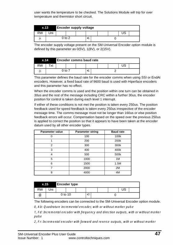
user wants the temperature to be checked. The Solutions Module will trip for overtemperature and thermistor short circuit.
The encoder supply voltage present on the SM-Universal Encoder option module isdefined by this parameter as 0(5V), 1(8V), or 2(15V).
This parameter defines the baud rate for the encoder comms when using SSI or EndAtencoders. However, a fixed baud rate of 9600 baud is used with Hiperface encodersand this parameter has no effect.
When the encoder comms is used and the position within one turn can be obtained in30us and the rest of the message including CRC within a further 30us, the encoderposition for control is taken during each level 1 interrupt.
If either of these conditions is not met the position is taken every 250us. The positionfeedback used for speed feedback is taken every 250us irrespective of the encodermessage time. The comms message must not be longer than 160us or else positionfeedback errors will occur. Compensation based on the speed over the previous 250usis applied to correct the position so that it appears to have been taken at the encoderdatum used by all other encoder types.
The following encoders can be connected to the SM-Universal Encoder option module.
0, Ab: Quadrature incremental encoder, with or without marker pulse
1, Fd: Incremental encoder with frequency and direction outputs, with or without markerpulse
2, Fr: Incremental encoder with forward and reverse outputs, with or without marker
x.13 Encoder supply voltage
RW Uni US
0 to 2 0
x.14 Encoder comms baud rate
RW Txt US
0 to 7 2
Parameter value Parameter string Baud rate
0 100 100k
1 200 200k
2 300 300k
3 400 400k
4 500 500k
5 1000 1M
6 1500 1.5M
7 2000 2M
8 4000 4M
x.15 Encoder type
RW Uni US
0 to 10 0
SM-Universal Encoder Plus User Guide 47Issue Number: 1 www.controltechniques.com

pulse
3, Ab.SErVO: Quadrature incremental encoder with commutation outputs, with orwithout marker pulse
4, Fd.SErVO: Incremental encoder with frequency, direction and commutation outputs,with or without marker pulse
5, Fr.SErVO: Incremental encoder with forward, reverse and commutation outputs, withor without marker pulse
6, SC: SinCos encoder with no serial communications
This type of encoder gives incremental position and can only be used for control inClosed-loop vector mode.
7, SC.HiPEr: Absolute SinCos encoder using Stegmann 485 comms protocol(HiperFace).
This type of encoder gives absolute position and can be used for motor control inclosed-loop vector or servo modes. The drive continuously checks the position from thesine and cosine waveforms against the internal encoder position using serialcommunications. If an error occurs the drive trips.
8, EndAt: Absolute EndAt only encoder
This type of encoder gives absolute position and can be used for motor control inclosed-loop vector or servo modes. Additional communications with the encoder is notpossible.
9, SC.EndAt:Absolute SinCos encoder using EndAt comms protocol
This type of encoder gives absolute position and can be used for motor control inclosed-loop vector or servo modes. The drive continuously checks the position from thesine and cosine waveforms against the internal encoder position using serialcommunications. If an error occurs the drive trips.
10, SSI: Absolute SSI only encoder
This type of encoder gives absolute position and can be used for motor control inclosed-loop vector or servo modes. Additional communications with the encoder is notpossible.
It should be noted that SC.HiPEr, SC.EndAt and EndAt must be initialised before theirposition data can be used. The encoder is automatically initialised at power-up, aftertrips 1 to 8 are reset, or when the initialisation parameter (Pr 3.48) is set to 1. If theencoder is not initialised or the initialisation is invalid the drive initiates trip 8.
The terminations may be enabled/disabled by this parameter as follows:
A-A\ and B-B\ terminations cannot be disabled when encoders with SinCos waveformsare selected.
x.16 Encoder termination
RW Txt US
0 to 2 1
Encoder input x.16=0 x.16=1 x.16=2
A-A\ Disabled Enabled Enabled
B-B\ Disabled Enabled Enabled
Z-Z\ Disabled Disabled Enabled
U-U\, V-V\, W-W\ Enabled Enabled Enabled
48 SM-Universal Encoder Plus User Guidewww.controltechniques.com Issue Number: 1

Z-Z\ terminations cannot be disabled except when Ab, Fd, Fr, Ab.SErVO, Fd.SErVO,Fr.SErVO encoders are selected.
Trips can be enabled/disabled using Pr x.17 as follows:
When a SC.HiPEr, SC.EndAt or EndAt encoder is being used, the Solutions Module willinterrogate the encoder on power-up. If Pr x.18 is set and the encoder type isrecognised, based on the information provided by the encoder the, Solutions Modulewill set the encoder turns (Pr x.09), the equivalent lines per revolution (Pr x.10) and theencoder comms resolution (Pr x.11) for the encoder. If the encoder is recognised theseparameters will all become read only. If the encoder is not recognised, the SolutionsModule will initiate a trip 7 to prompt the user to enter the information. The SolutionsModule should be able to auto-configure with any EndAt encoder where the number ofturns and line per revolution are a power of 2, and the following Hiperface encoders:SCS 64/70, SCM 60/70, SRS 50/60, SRM 50/60, SHS 170, LINCODER, SCS-KIT 101,SKS36, SKM36
SSISSI encoders normally use Gray code data format. However, some encoders use binaryformat which may be selected by setting this parameter to 1.
A sliding window filter may be applied to the feedback. This is particularly useful inapplications where the feedback is used to give speed feedback for the speed controllerand where the load includes a high inertia, and so the speed controller gains are veryhigh. Under these conditions, without a filter on the feedback, it is possible for the speedloop output to change constantly from one current limit to the other and lock the integralterm of the speed controller.
x.17 Error detection level
RW Uni US
0 to 7 0
Bit Function
0 Wire break detect
1 Phase error detect
2 SSI power supply monitor
x.18 Auto configuration enable / SSI binary format select
RW Bit US
OFF (0) or On (1) OFF (0)
x.19 Feedback filter
RW Uni US
0 to 16ms 0
x.20 Maximum feedback reference
RW Uni US
0.0 to 40,000.0rpm
SM-Universal Encoder Plus User Guide 49Issue Number: 1 www.controltechniques.com

The position feedback can be used as a reference for any unprotected parameter. Thepercentage of the maximum position feedback reference (Pr x.20) is calculated anddisplayed via the feedback reference (Pr x.21). The value written to the destinationparameter is a percentage of the full-scale value of the destination defined by Pr x.23.
To enable a faster update rate, if the destination for the feedback is the hard speedreference (Pr 3.22), a shortcut facility is provided in the drive. In order to invoke thisfacility, the maximum feedback reference (Pr x.20) must be set to the maximumcurrently used for the hard speed reference.
An encoder simulation output can be generated from any parameter as a source asdefined by Pr x.24 (00.00 disables encoder simulation). Although any parameter can beused, the source parameter is assumed to be a 16 bit position value in the form of a roll-over counter. Therefore only parameters with a range of -32768 to 32767 or 0 to 65535
x.21 Feedback reference
RO Bi NC PT
-100.0 to 100.00%
x.22 Feedback reference scaling
RW Uni US
0.000 to 4.000 1.000
x.23 Feedback reference destination
RW Uni DE US
00.00 to 21.51 00.00
x.24 Encoder simulation source
RW Uni PT US
00.00 to 21.51 00.00
x.25 Encoder simulation ratio numerator
RW Uni US
0.0000 to 3.0000 1.0000
x.26 Encoder simulation ratio denominator
RW Uni US
0.0000 to 3.0000 1.0000
x.27 Encoder simulation resolution select
RW Bit NC US
OFF (0) or On (1) OFF (0)
50 SM-Universal Encoder Plus User Guidewww.controltechniques.com Issue Number: 1

are normally used. The marker is simulated when the source rolls over or under.
When the Solutions Module is connected to a high precision encoder (i.e. SinCos) andthe source has been selected as the internal position (Pr x.05), the resolution can beincrease to a 24 bit position value by setting Pr x.27 to a one.
This parameter defines the output mode for encoder simulation as follows.
The marker pulse is simulated if the marker output port is not being used for RS485freeze input.
This position is taken from the position feedback device and is not affected by themarker or the freeze inputs.
x.28 Encoder simulation mode
RW Txt US
0 to 2 0
Pr x.28 String Mode
0 Ab Quadrature
1 Fd Frequency and direction
2 SSI SSI
x.29 Non-marker reset revolution counter
RO Uni NC PT
0 to 65535 revolutions
x.30 Non-marker reset position
RO Uni NC PT
0 to 65535 (1/216ths of arevolution)
x.31 Non-marker reset fine position
RO Uni NC PT
0 to 65535 (1/232nds of arevolution)
x.32 Marker revolution counter
RO Uni NC PT
0 to 65535 revolutions
x.33 Marker position
RO Uni NC PT
0 to 65535 (1/216ths of arevolution)
SM-Universal Encoder Plus User Guide 51Issue Number: 1 www.controltechniques.com

Each time the marker becomes active the non-marker position values (Pr x.29 to Prx.31) are sampled and stored in Pr x.32 to Pr x.34.
The freeze input can take the form of either a 485 signal through the encoder markersimulation output pins or a 24V signal on the freeze 24V input. The selection of whichmode is used is dependent on the value of Pr x.38.
Each time the freeze input on the Solutions Module becomes active the non-markerposition (Pr x.29 to Pr x.31) is stored in Pr x.35 to Pr x.37 and the freeze flag (Pr x.39)is set. The freeze flag is not reset by the module and must be reset by the user. No other
x.34 Marker fine position
RO Uni NC PT
0 to 65535 (1/232nds of arevolution)
x.35 Freeze revolution counter
RO Uni NC PT
0 to 65535 revolutions
x.36 Freeze position
RO Uni NC PT
0 to 65535 (1/216ths of arevolution)
x.37 Freeze fine position
RO Uni NC PT
0 to 65535 (1/232nds of arevolution)
x.38 Freeze input mode select
RW Uni US
0 to 3 1
Value in x.38 24V input 485 input
0 No No
1 Yes No
2 No Yes
3 Yes Yes
x.39 Freeze flag
RW Bit NC
OFF (0) or On (1) OFF (0)
52 SM-Universal Encoder Plus User Guidewww.controltechniques.com Issue Number: 1

freeze conditions will be trapped if the flag is set.
When a freeze occurs on the Solutions Module the main drive position can also bestored if this parameter is set to one. Whenever a SM-Applications and a SM-UniversalEncoder Plus are used, the freeze should be connected to the SM-Universal EncoderPlus, Pr x.40 should be set to allow the drive and the SM-Applications to see the freeze.
When Pr x.41 = 0 freeze occurs on the rising edge of the freeze input. When Pr x.41 = 1freeze occurs on the falling edge of the freeze input.
If Pr x.44 is zero the drive can check the position derived with the sine and cosinewaveforms from a SinCos encoder via serial communications. If Pr x.44 is set to one thechecking is disabled and encoder comms is available via the transmit and receiveregisters.
At power-up Pr x.45 is initially zero, but is set to one when the encoder connected toposition module has been initialised. The drive cannot be enabled until this parameter isone.
If the encoder power-supply is lost, or the encoder type parameter is changed for anencoder connected to a the Solutions Module, and the encoder type is SC, SC.HiPEr,SC.EndAt or EndAt the encoder will no longer be initialised. When an encoder is no
x.40 Freeze main drive position
RW Bit NC US
OFF (0) or On (1) OFF (0)
x.41 Freeze invert
RW Bit US
OFF (0) or On (1) OFF (0)
x.42 Encoder comms transmit register
RW Uni NC
0 to 65535
x.43 Encoder comms receive register
RW Uni NC
0 to 65535 0
x.44 Disable encoder position check
RW Bit NC PT
OFF (0) or On (1) OFF (0)
x.45 Position feedback initialised
RO Bit NC PT
SM-Universal Encoder Plus User Guide 53Issue Number: 1 www.controltechniques.com

longer initialised Pr x.45 is reset to zero and the drive cannot be enabled. The encodermay be re-initialised, provided the drive is not active, by setting Pr 3.48 to one. Thisparameter is automatically reset to zero when the initialisation is complete.
The equivalent line per revolution parameter (Pr x.10) is divided by the value in Pr x.46.This can be used when an encoder is used with a linear motor where the number ofcounts or sine waves per pole is not an integer.
For example, 128.123 lines per revolution would be set as 128123 in Pr x.10 and 1000in Pr x.46 giving:
128123 / 1000 = 128.123.
Used by the simulation module.
Used by the simulation module.
The error status is provided so that the only one option error trip is required for eachoption module slot. If an error occurs, the reason for the error is written to this parameterand the drive may produce a ‘SLX.Er’ trip, where x is the slot number. A value of zeroindicates that the Solutions Module has not detected an error, a non-zero valueindicates that an error has been detected. (See Chapter 8 Diagnostics for the meaningof the values in this parameter.) When the drive is reset, this parameter is cleared for therelevant Solutions Module.
All Solutions Modules include a temperature monitoring circuit. If the PCB temperatureexceeds 90°C, the drive fan is forced to operate at full speed (for a minimum of 10s). Ifthe temperature falls below 90°C, the fan can operate normally again. If the PCBtemperature exceeds 100°C, the drive is tripped and the error status is set to 74.
x.46 Line per revolution divider
RW Uni US
0 to 1024 1
x.47 SSI output turns
RW Uni US
0 to 16 16
x.48 SSI output comms resolution
RW Uni US
0 to 32 bits 0
x.50 Solutions Module error status
RO Uni NC PT
0 to 255
54 SM-Universal Encoder Plus User Guidewww.controltechniques.com Issue Number: 1

8 DiagnosticsIf the drive trips, the output is disabled so that the drive stops controlling the motor. Thelower display indicates that a trip has occurred and the upper display shows the trip.
Trips are listed alphabetically in Table 8.1 based on the trip indication shown on thedrive display. Refer to Figure 8-1.
If a display is not used, the drive LED Status indicator will flash if the drive has tripped.Refer to Figure 8-2.
The trip indication can be read in Pr 10.20 providing a trip number.
8.1 Displaying the trip historyThe drive retains a log of the last 10 trips that have occurred in Pr 10.20 to Pr 10.29 andthe corresponding time for each trip in Pr 10.43 to Pr 10.51. The time of the trip isrecorded from the powered-up clock (if Pr 6.28 = 0) or from the run time clock (if Pr 6.28= 1).
Pr 10.20 is the most recent trip, or the current trip if the drive is in a trip condition (withthe time of the trip stored in Pr 10.43). Pr 10.29 is the oldest trip (with the time of the tripstored in Pr 10.51). Each time a new trip occurs, all the parameters move down one,such that the current trip (and time) is stored in Pr 10.20 (and Pr 10.43) and the oldesttrip (and time) is lost out of the bottom of the log.
If any parameter between Pr 10.20 and Pr 10.29 inclusive is read by serialcommunications, then the trip number in Table 8-1 is the value transmitted.
Figure 8-1 Keypad status modes
Figure 8-2 Location of the status LED
Trip type (UU= undervolts)
Drive status= tripped
Trip StatusAlarm StatusHealthy Status
Status Mode
Status LED
Non flashing:Normal status
Flashing:Trip status
SM-Universal Encoder Plus User Guide 55Issue Number: 1 www.controltechniques.com

Any trip can be initiated by writing the relevant trip number to Pr 10.38. If any tripsshown as user trips are initiated the trip string is "txxx", where xxx is the trip number.
Trips can be reset after 1.0s if the cause of the trip has been rectified.
A full list of drive trips can be found in the Unidrive SP User Guide.
Table 8.1 Trip codes
Trip Diagnosis
C.OptnSMARTCARD trip: Solutions Modules fitted are different between source driveand destination drive
180Ensure correct Solutions Modules are fittedEnsure Solutions Modules are in the same Solutions Module slot
Press the red reset button
Enc1 Drive encoder trip: Encoder power supply overload
189Check encoder power supply wiring and encoder current requirementMaximum current = 200mA @ 15V or 300mA @ 8V and 5V
ENP.ErData error from electronic nameplate stored in selected position feedbackdevice
178 Replace feedback device
PS.24V 24V internal power supply overload
9
The total user load of the drive and Solutions Modules has exceeded the internal 24Vpower supply limit.The user load consists of the drive’s digital outputs plus the SM-I/O Plus digitaloutputs, or the drive’s main encoder supply plus the SM-Universal Encoder Plusencoder supply.• Reduce load and reset• Provide an external 24V >50W power supply• Remove any Solutions Modules and reset
SLX.dF Solutions Module slot X trip: Solutions Module type fitted in slot X changed
204,209,214
Save parameters and reset
56 SM-Universal Encoder Plus User Guidewww.controltechniques.com Issue Number: 1

SLX.ErSolutions Module slot X trip: Error detected with Solutions Module, where X isthe slot number
202207212
* - Phase errors are detected when the error is greater than 10o electrical over tenconsecutive one second samples.
+ - These trips can be enabled/disabled by Pr x.17.
# - If the terminations are not enabled on the A, B or Z inputs the wire break system willnot operate. (Note that as default the Z input terminations are disabled to disable wirebreak detection on this input.)
Encoder initialisation will occur when trips 1 to 8 are reset. This causes an encoderwith comms to be re-initialised and auto-configuration to be performed if selected.
It is important that a break in the connections between the drive and the positionfeedback device can be detected. This feature is provided either directly or indirectlyas listed.When the drive is reset this parameter is cleared for the relevant Solutions Module
SLX.HF Solutions Module slot X trip: Solutions Module X hardware fault
200,205,210
Ensure Solutions Module is fitted correctlyReturn Solutions Module to supplier
Trip Diagnosis
Errorcode
Encoders Reason for error
0 All No fault detected
1 All Power supply short circuit
2Ab, Fd, Fr, Ab.SErVO,
Fd.SErVO, Fr.SErVO, SC,SC.HiPEr, SC.EndAt, SSI
Hardware detectors on the A(F), B(D,R) and Z signaldetect a wire break.The differential levels of the sine and cosinewaveforms are available to the drive. The drivedetects wire break if Sine2+Cosine2 is less than thevalue produced by two valid waveforms with adifferential peak to peak magnitude of 0.25V (1/4 ofthe nominal level). This detects wire break in the sineand cosine connections.
3Ab.SErVO, Fd.SErVO,
Fr.SErVO,SC.HiPEr, SC.EndAt
+UVW phase angle incorrect whilst running, i.e.incremental pulses not counted correctly.+*Sine/cosine phase error.
4 SC.HiPEr Wire break in the comms link is detected by a CRC ortimeout error.Data line (Z) checked.5 SC.HiPEr, SC.EndAt, EndAt
6SC.HiPEr, SC.EndAt, SSI,
EndAt The encoder has indicated an error
7 SC.HiPEr, SC.EndAt, EndAt The encoder has failed to initialise.
8 SC.HiPEr, SC.EndAt, EndAt
Auto parameter configuration on power-up has beenrequested Pr x.17 > 1 but the encoder type has notbeen recognised. The user must supply Pr x.09 andPr x.11, and possibly Pr x.10.
9 All Thermistor trip
10 All Thermistor short circuit
74 All The Solutions Module has overheated.
SM-Universal Encoder Plus User Guide 57Issue Number: 1 www.controltechniques.com

SLX.nF Solutions Module slot X trip: Solutions Module has been removed
203,208,213
Ensure Solutions Module is fitted correctlyReplace Solutions ModuleSave parameters and reset drive
SLX.tO Solutions Module slot X trip: Solutions Module watchdog time-out
203,208,211
Press reset.If the trip persists, contact the supplier of the drive.
SL.rtdSolutions Module trip: Drive mode has changed and Solutions Moduleparameter routing is now incorrect
215Press reset.If the trip persists, contact the supplier of the drive.
Trip Diagnosis
58 SM-Universal Encoder Plus User Guidewww.controltechniques.com Issue Number: 1

9 Terminal Data
9.1 Encoder inputs SK1Ab, Fd, Fr, Ab.SErVO, Fd.SErVO and Fr.SErVO encoders
SC, SC.HiPEr and SC.EndAt encoders
1 Channel A, Frequency or Forward inputs
2 Channel A\, Frequency\ or Forward\ inputs
3 Channel B, Direction or Reverse inputs
4 Channel B\, Direction\ or Reverse\ inputs
5 Marker pulse channel Z
6 Marker pulse channel Z\
7 Phase channel U
8 Phase channel U\
9 Phase channel V
10 Phase channel V\
11 Phase channel W
12 Phase channel W\
Type EIA 485 differential receivers
Maximum frequency 600kHz
Line loading<2 unit loads (for terminals 1 to 4)32 unit loads (for terminals 5 and 6)1 unit load (for terminals 7 to 12)
Line termination components 120Ω
Working common mode range +12V to –7V
Absolute maximum applied voltage relative to0V
±14V
Absolute maximum applied differential voltage ±14V
1 Channel Cos
2 Channel Cos\
3 Channel Sin
4 Channel Sin\
Type Differential voltage
Maximum signal level 1.25V peak to peak
Maximum frequency 100kHz
Maximum applied differential voltage ±1.5V
SM-Universal Encoder Plus User Guide 59Issue Number: 1 www.controltechniques.com

SC.HiPEr, SC.EndAt, EndAt and SSI encoders
*** Not used with SC.HiPEr encoders.
9.2 Simulated encoder outputs SK1Simulated Ab, Fd encoder outputs
.
5 Data
6 Data\
9 Clock***
10 Clock\***
Type EIA 485 differential transceivers
Maximum frequency 2MHz
Line loading32 unit loads (for terminals 5 and 6)1 unit load (for terminals 11 and 12)
Working common mode range +12V to –7V
Absolute maximum applied voltage relative to0V ±14V
Absolute maximum applied differential voltage ±14V
7 Frequency output F, Quadrature output A
8 Frequency output F\, Quadrature output A\
9 Frequency output D, Quadrature output B
10 Frequency output D\, Quadrature output B\
Type EIA 485 differential receivers
Maximum frequency 500kHz
Line loading<2 unit loads (for terminals 1 to 4)32 unit loads (for terminals 5 and 6)1 unit load (for terminals 7 to 12)
Line termination components 120Ω
Working common mode range +12V to –7V
Absolute maximum applied voltage relative to0V ±14V
Absolute maximum applied differential voltage ±14V
The simulated encoder outputs available on terminal PL2 are identical to the simulatedencoder outputs available on terminal SK1 (internally connected)
NOTE
60 SM-Universal Encoder Plus User Guidewww.controltechniques.com Issue Number: 1

Simulated SSI encoder output (binary format)
9.3 Drive encoder power supplyCommon to all Encoder types
The encoder supply voltage is controlled by Pr x.13. The default for this parameter is 5V(0) but this can be set to 8V (1) or 15V (2). Setting the encoder voltage supply too highfor the encoder could result in damage to the feedback device.
The termination resistors should be disabled if the outputs from the encoder are higherthan 5V.
5 Data
6 Data\
7 Data
8 Data\
9 Clock
10 Clock\
Type EIA 485 differential transceivers
Maximum frequency 500kHz
Line loading32 unit loads (for terminals 5 and 6)1 unit load (for terminals 11 and 12)
Working common mode range +12V to –7V
Absolute maximum applied voltage relative to0V
±14V
Absolute maximum applied differential voltage ±14V
13 Encoder supply voltage
Supply voltage 5V, 8V or 15V
Maximum output current300mA for 5V and 8V200mA for 15V
14 0V common
15 Motor thermistor input
SM-Universal Encoder Plus User Guide 61Issue Number: 1 www.controltechniques.com
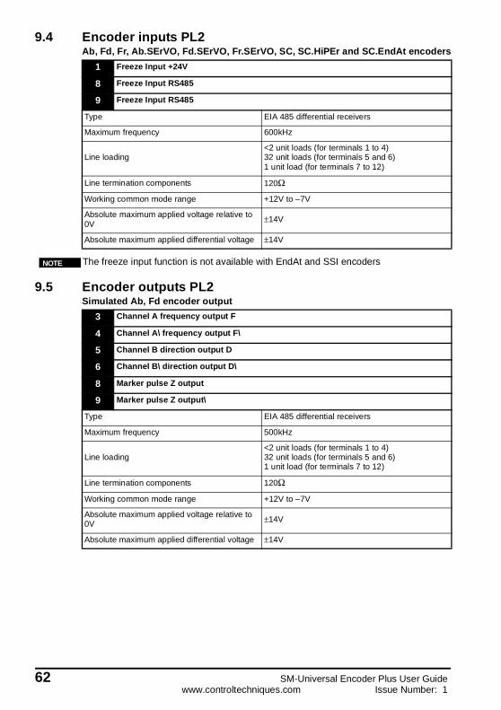
9.4 Encoder inputs PL2Ab, Fd, Fr, Ab.SErVO, Fd.SErVO, Fr.SErVO, SC, SC.HiPEr and SC.EndAt encoders
9.5 Encoder outputs PL2Simulated Ab, Fd encoder output
1 Freeze Input +24V
8 Freeze Input RS485
9 Freeze Input RS485
Type EIA 485 differential receivers
Maximum frequency 600kHz
Line loading<2 unit loads (for terminals 1 to 4)32 unit loads (for terminals 5 and 6)1 unit load (for terminals 7 to 12)
Line termination components 120Ω
Working common mode range +12V to –7V
Absolute maximum applied voltage relative to0V
±14V
Absolute maximum applied differential voltage ±14V
The freeze input function is not available with EndAt and SSI encodersNOTE
3 Channel A frequency output F
4 Channel A\ frequency output F\
5 Channel B direction output D
6 Channel B\ direction output D\
8 Marker pulse Z output
9 Marker pulse Z output\
Type EIA 485 differential receivers
Maximum frequency 500kHz
Line loading<2 unit loads (for terminals 1 to 4)32 unit loads (for terminals 5 and 6)1 unit load (for terminals 7 to 12)
Line termination components 120Ω
Working common mode range +12V to –7V
Absolute maximum applied voltage relative to0V ±14V
Absolute maximum applied differential voltage ±14V
62 SM-Universal Encoder Plus User Guidewww.controltechniques.com Issue Number: 1

Simulated SSI encoder output (binary format)
5 Data output
6 Data output\
9 Clock output
10 Clock output\
Type EIA 485 differential transceivers
Maximum frequency 500kHz
Line loading32 unit loads (for terminals 5 and 6)1 unit load (for terminals 11 and 12)
Working common mode range +12V to –7V
Absolute maximum applied voltage relative to0V ±14V
Absolute maximum applied differential voltage ±14V
The simulated encoder outputs available on terminal PL2 are identical to the simulatedencoder outputs available on terminal SK1 (internally connected)
NOTE
SM-Universal Encoder Plus User Guide 63Issue Number: 1 www.controltechniques.com

Index
CCautions 2Colour coding 4Comms only absolute encoder basic set-up 22Comms only, absolute encoders 22Commutation signals 6Compatible with encoder types 5Compliance 3
DData transferral via comms 35Diagnostics 55Drive encoder power supply 61
EElectrical noise 18Electrical safety 2Electronic nameplate transfers 36Encoder circuit with Galvanic Isolation from encoder body 15Encoder comms baud rate 34Encoder inputs PL2 62Encoder inputs SK1 59Encoder outputs PL2 62Encoder receive 28Encoder simulation resolution 50Encoder transmit 28Encoder type 47Encoder with Galvanic Isolation from motor 14EndAt comms 35EndAt encoder 18EndAt encoder comms baud rate 34Environmental limits 3Error detection level 49Error status 54
FFeatures 4Feedback cable 17Feedback cable connections 17Feedback filter 49Freeze data 26Freeze flag 26Freeze input mode 52Freeze input with SM-Applications option module 27Freeze inputs 26
GGalvanically isolated 16Ground clamps 17
64 SM-Universal Encoder Plus User Guidewww.controltechniques.com Issue Number: 1

HHiperface encoders 18
IIncremental absolute encoder basic set-up 21Incremental absolute encoders 21Incremental encoder basic set-up 19Incremental encoders 5, 19Incremental plus commutation 6Incremental plus commutation encoder basic set-up 20Incremental plus commutation, Absolute encoders 20Installation 18
KKeypad status modes 55
LLimitations 5Line loading - PL2 62, 63Line loading - SK1 59, 60, 61Line per revolution divider 54Loading object parameters 36Logic diagram 42
MMain feedback 18Marker data 25Marker flag 25Marker inputs 25Maximum frequency - PL2 62, 63Maximum frequency - SK1 59, 60, 61Maximum output current - drive encoder power supply 61Maximum signal level - SK1 59Maximum voltage - PL2 62, 63Maximum voltage - SK1 60, 61
NNo Isolation 15No isolation 16Non marker data 26
OOption ID code 44
PParameter - single line descriptions 40Parameter coding 39Parameter descriptions 44Parameter structure 39Parameters - adjusting 3Parameters - motor object 37Parameters - performance object 38Power cables 17Power supply overload 56
SM-Universal Encoder Plus User Guide 65Issue Number: 1 www.controltechniques.com

RReceive register 21
SSafety of personnel 2SC.EndAt 31SC.EndAt positional data transfer 32SC.HiPEr 29SC.HiPEr positional data transfer 30Screen connections 16SECURE DISABLE 2Serial communications 28Set-up parameters 4Simulated encoder output resolution 23Simulated encoder output SSI 24Simulated encoder outputs 23Simulated encoder outputs SK1 60Simulated marker outputs 26SinCos 28SinCos encoder comms baud rate 28SinCos encoder feedback signals 8Software simulation - high resolution encoder 23Software version 44Solutions Module identification 4SSI - EndAt 34SSI comms 36SSI encoder comms baud rate 34Storing object parameters 36
TTemperature monitoring circuit 54Termination - PL2 62Termination - SK1 59, 60Termination resistors 23Transmit registers 21Trip history 55
WWarnings 2
66 SM-Universal Encoder Plus User Guidewww.controltechniques.com Issue Number: 1


