USER GUIDE PTP TD90 Series - Cambium Networks · USER GUIDE PTP 700 TD90 Series. phn-4706 (June...
86
USER GUIDE PTP 700 TD90 Series
Transcript of USER GUIDE PTP TD90 Series - Cambium Networks · USER GUIDE PTP 700 TD90 Series. phn-4706 (June...

USER GUIDE
PTP 700 TD90 Series

phn-4706 (June 2018)
Accuracy While reasonable efforts have been made to assure the accuracy of this document, Cambium Networks assumes no liability resulting from any inaccuracies or omissions in this document, or from use of the information obtained herein. Cambium reserves the right to make changes to any products described herein to improve reliability, function, or design, and reserves the right to revise this document and to make changes from time to time in content hereof with no obligation to notify any person of revisions or changes. Cambium does not assume any liability arising out of the application or use of any product, software, or circuit described herein; neither does it convey license under its patent rights or the rights of others. It is possible that this publication may contain references to, or information about Cambium products (machines and programs), programming, or services that are not announced in your country. Such references or information must not be construed to mean that Cambium intends to announce such Cambium products, programming, or services in your country. Copyrights This document, Cambium products, and 3rd Party software products described in this document may include or describe copyrighted Cambium and other 3rd Party supplied computer programs stored in semiconductor memories or other media. Laws in the United States and other countries preserve for Cambium, its licensors, and other 3rd Party supplied software certain exclusive rights for copyrighted material, including the exclusive right to copy, reproduce in any form, distribute and make derivative works of the copyrighted material. Accordingly, any copyrighted material of Cambium, its licensors, or the 3rd Party software supplied material contained in the Cambium products described in this document may not be copied, reproduced, reverse engineered, distributed, merged or modified in any manner without the express written permission of Cambium. Furthermore, the purchase of Cambium products shall not be deemed to grant either directly or by implication, estoppel, or otherwise, any license under the copyrights, patents or patent applications of Cambium or other 3rd Party supplied software, except for the normal non-exclusive, royalty free license to use that arises by operation of law in the sale of a product. Restrictions Software and documentation are copyrighted materials. Making unauthorized copies is prohibited by law. No part of the software or documentation may be reproduced, transmitted, transcribed, stored in a retrieval system, or translated into any language or computer language, in any form or by any means, without prior written permission of Cambium. License Agreements The software described in this document is the property of Cambium and its licensors. It is furnished by express license agreement only and may be used only in accordance with the terms of such an agreement. High Risk Materials Cambium and its supplier(s) specifically disclaim any express or implied warranty of fitness for any high risk activities or uses of its products including, but not limited to, the operation of nuclear facilities, aircraft navigation or aircraft communication systems, air traffic control, life support, or weapons systems (“High Risk Use”). Any “High Risk Use” is unauthorized, is made at your own risk and you shall be responsible for any and all losses, damage or claims arising out of any High Risk Use.
© 2018 Cambium Networks Limited. All Rights Reserved.
Page i
Contents
Cambium PTP 700 TD90 Series User Guide ........................................................................................................... 1 Contents ................................................................................................................................................................. i List of Figures ........................................................................................................................................................ iii List of Tables ......................................................................................................................................................... iv About This User Guide ........................................................................................................................................ 1-1
Contacting Cambium Networks .................................................................................................................. 1-1 Purpose ....................................................................................................................................................... 1-1 Cross references .......................................................................................................................................... 1-1 Feedback ..................................................................................................................................................... 1-2
Problems and warranty ...................................................................................................................................... 1-3 Reporting problems ..................................................................................................................................... 1-3 Repair and service ....................................................................................................................................... 1-3 Hardware warranty ..................................................................................................................................... 1-3
Security advice .................................................................................................................................................... 1-4 Warnings, cautions, and notes ........................................................................................................................... 1-5
Warnings ..................................................................................................................................................... 1-5 Cautions ....................................................................................................................................................... 1-5 Notes ........................................................................................................................................................... 1-5
Caring for the environment ................................................................................................................................ 1-6 In EU countries ............................................................................................................................................ 1-6 In non-EU countries ..................................................................................................................................... 1-6
Chapter 1: TD90 Modes of Operation ............................................................................................................. 1-7 Mode 3 Operation (Default) ............................................................................................................................... 1-8 Mode 2 Operation .............................................................................................................................................. 1-9 Mode 1 Operation ............................................................................................................................................ 1-10
Chapter 2: TD90 Pre-configuration ............................................................................................................... 2-11 Pre-configuration Requirements Mode 2/3 (Default mode) ............................................................................ 2-12 Pre-configuration Requirements Mode 1 ......................................................................................................... 2-13 Pre-configuration Instructions for Modes 1, 2, and 3 ....................................................................................... 2-14
Chapter 3: Quick Setup Guide for Deployment ............................................................................................. 3-21 Step 1 - Mount TD90 to tower or mast ............................................................................................................. 3-22 Step 2 - Mount TD90 Top Plate Bracket ............................................................................................................ 3-23 Step 3 - Mount PTP 700 .................................................................................................................................... 3-24 Step 4 - Connect Radio to TD90 ........................................................................................................................ 3-25 Step 5 - Connect TD90 for operation ................................................................................................................ 3-26 Step 6 - Power Up ............................................................................................................................................. 3-27
Chapter 4: TD90 Mechanical and Electrical Interfaces .................................................................................. 4-28

Contents
Page ii
TD90 Base Mount Surface and Dimensions ...................................................................................................... 4-29 Antenna Mount Surface and Dimensions ......................................................................................................... 4-30 TD Interface Details .......................................................................................................................................... 4-31
Front Surface of TD90................................................................................................................................ 4-31 Left Surface of TD90 .................................................................................................................................. 4-32 Rear Surface of TD90 ................................................................................................................................. 4-33 Right Side Surface of TD90 ........................................................................................................................ 4-35 Pass-through Pinouts for PSU Ethernet ..................................................................................................... 4-36 Pass-through Pinouts for AUX Ethernet .................................................................................................... 4-36
Chapter 5: Web Based User Interface ........................................................................................................... 5-38 TD90 Home ....................................................................................................................................................... 5-39 TD90 Setup ........................................................................................................................................................ 5-43 TD90 Manual Control ........................................................................................................................................ 5-45 TD90 Positioner Configuration.......................................................................................................................... 5-47 TD90 Compass .................................................................................................................................................. 5-49 TD90 Errors ....................................................................................................................................................... 5-51
Chapter 6: Setup Validation and Troubleshooting ........................................................................................ 6-55 Testing Connection to PTP 700 ......................................................................................................................... 6-56 Testing Connection to TD90 .............................................................................................................................. 6-68 PTP 700 and TD90 Connection .......................................................................................................................... 6-73 Troubleshooting Connectivity between PTP 700 and TD90 ............................................................................. 6-75 Over the Air Connectivity of PTP 700 Link ........................................................................................................ 6-79

List of Figures
Page iii
List of Figures
Figure 1 Setup of TD90 to pre-configure ................................................................................................................. 2-14 Figure 2 Change adapter settings ............................................................................................................................ 2-15 Figure 3 Local Area Connection ............................................................................................................................... 2-15 Figure 4 Select “Properties” .................................................................................................................................... 2-16 Figure 5 Select “Internet Protocol Version 4 (TCP/IPv4)” ........................................................................................ 2-17 Figure 6 Select IP and Subnet Mask Settings ........................................................................................................... 2-17 Figure 7 Home page with System Summary ............................................................................................................ 2-18 Figure 8 System Setup page..................................................................................................................................... 2-19 Figure 9 Mode 2 and 3 setup requirements ............................................................................................................ 2-19 Figure 10 Optional Mode 1 Setup ............................................................................................................................ 2-20 Figure 11 Step 1 - TD90 with HD Mast Mounting Bracket ....................................................................................... 3-22 Figure 12 Step 2 - TD90 with TD90 Top Plate Bracket ............................................................................................. 3-23 Figure 13 Step 3 - TD90 with TD90 Top Plate Bracket and PTP 700 mounted to front ........................................... 3-24 Figure 14 Step 4 – PTP 700 to TD90 ......................................................................................................................... 3-25 Figure 15 Step 5 - From – To connection diagram ................................................................................................... 3-26 Figure 16 Bottom view of TD90 with dimensioned hole pattern ............................................................................ 4-29 Figure 17 Antenna mount surface with dimensioned hole pattern ........................................................................ 4-30 Figure 18 Front Surface of TD90 .............................................................................................................................. 4-31 Figure 19 Connector Pinout for Optional DC Power Input ...................................................................................... 4-31 Figure 20 Left Side Surface of TD90 ......................................................................................................................... 4-32 Figure 21 Connector Pinout for GPS input .............................................................................................................. 4-32 Figure 22 Rear Surface of TD90 .............................................................................................................................. 4-33 Figure 23 Connector Pinout for TD90 Data and Power input ................................................................................. 4-34 Figure 24 Right Side Surface of TD90 ...................................................................................................................... 4-35

List of Tables
Page iv
List of Tables
Table 1 Home page descriptions ............................................................................................................................. 5-41 Table 2 Setup page descriptions .............................................................................................................................. 5-43 Table 3 Manual control page descriptions .............................................................................................................. 5-46 Table 4 Positioner control page descriptions .......................................................................................................... 5-47 Table 5 Home page descriptions ............................................................................................................................. 5-49 Table 6 Error descriptions and possible fixes .......................................................................................................... 5-52

Index TD90 Modes of Operation
1-1
About This User Guide
This document explains how to deploy a TD90 Antenna Positioner and PTP 700 on a 18 meter HD Mast along with important safety measures. It is intended for use by the system designer, system installer and system administrator.
Contacting Cambium Networks Support website: https://support.cambiumnetworks.com
Main website: http://www.cambiumnetworks.com
Sales enquiries: [email protected]
Support enquiries: https://support.cambiumnetworks.com
Repair enquiries: https://support.cambiumnetworks.com
Telephone number list: http://www.cambiumnetworks.com/contact
Address: Cambium Networks Limited, Global Headquarters, 3800 Golf Road, Suite 360, Rolling Meadows,
IL 60008 USA
Purpose Cambium Networks Point-To-Point (PTP) documents are intended to instruct and assist personnel in the operation, installation and maintenance of the Cambium Networks PTP equipment and ancillary devices. It is recommended that all personnel engaged in such activities be properly trained.
Cambium Networks disclaims all liability whatsoever, implied or express, for any risk of damage, loss or reduction in system performance arising directly or indirectly out of the failure of the customer, or anyone acting on the customer's behalf, to abide by the instructions, system parameters, or recommendations made in this document.
Cross references References to external publications are shown in italics. Other cross references, emphasized in blue text in electronic versions, are active links to the references.

List of Tables
Page 1-2
This document is divided into numbered chapters that are divided into sections. Sections are not numbered but are individually named at the top of each page, and are listed in the table of contents.
Feedback We appreciate feedback from the users of our documents. This includes feedback on the structure, content, accuracy, or completeness of our documents. To provide feedback, visit our support website.https://support.cambiumnetworks.com.

List of Tables
Page 1-3
Problems and warranty
Reporting problems If any problems are encountered when installing or operating this equipment, follow this procedure to investigate and report:
1 Search this document and the software release notes of supported releases.
2 Visit the support website.
3 Ask for assistance from the Cambium product supplier.
4 Gather information from affected units, such as any available diagnostic downloads.
5 Escalate the problem by emailing or telephoning support.
Repair and service If unit failure is suspected, obtain details of the Return Material Authorization (RMA) process from the support website (http://www.cambiumnetworks.com/support).
Hardware warranty Cambium’s standard hardware warranty is for one (1) year from date of shipment from Cambium Networks or a Cambium distributor. Cambium Networks warrants that hardware will conform to the relevant published specifications and will be free from material defects in material and workmanship under normal use and service. Cambium shall within this time, at its own option, either repair or replace the defective product within thirty (30) days of receipt of the defective product. Repaired or replaced product will be subject to the original warranty period but not less than thirty (30) days.
To register PMP and PTP products or activate warranties, visit the support website. For warranty assistance, contact the reseller or distributor. The removal of the tamper-evident seal will void the warranty.
Caution
Using non-Cambium parts for repair could damage the equipment or void warranty. Contact Cambium for service and repair instructions.
Portions of Cambium equipment may be damaged from exposure to electrostatic discharge. Use precautions to prevent damage.
List of Tables
Page 1-4
Security advice
Cambium Networks systems and equipment provide security parameters that can be configured by the operator based on their particular operating environment. Cambium recommends setting and using these parameters following industry recognized security practices. Security aspects to be considered are protecting the confidentiality, integrity, and availability of information and assets. Assets include the ability to communicate, information about the nature of the communications, and information about the parties involved.
In certain instances, Cambium makes specific recommendations regarding security practices, however the implementation of these recommendations and final responsibility for the security of the system lies with the operator of the system.
List of Tables
Page 1-5
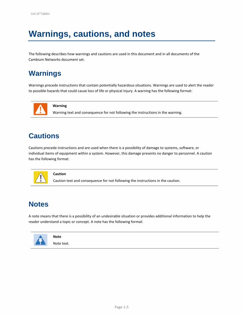
Warnings, cautions, and notes
The following describes how warnings and cautions are used in this document and in all documents of the Cambium Networks document set.
Warnings Warnings precede instructions that contain potentially hazardous situations. Warnings are used to alert the reader to possible hazards that could cause loss of life or physical injury. A warning has the following format:
Warning
Warning text and consequence for not following the instructions in the warning.
Cautions Cautions precede instructions and are used when there is a possibility of damage to systems, software, or individual items of equipment within a system. However, this damage presents no danger to personnel. A caution has the following format:
Caution
Caution text and consequence for not following the instructions in the caution.
Notes A note means that there is a possibility of an undesirable situation or provides additional information to help the reader understand a topic or concept. A note has the following format:
Note
Note text.

List of Tables
Page 1-6
Caring for the environment
The following information describes national or regional requirements for the disposal of Cambium Networks supplied equipment and for the approved disposal of surplus packaging.
In EU countries The following information is provided to enable regulatory compliance with the European Union (EU) directives identified and any amendments made to these directives when using Cambium equipment in EU countries.
Disposal of Cambium equipment European Union (EU) Directive 2002/96/EC Waste Electrical and Electronic Equipment (WEEE)
Do not dispose of Cambium equipment in landfill sites. For disposal instructions, refer to
http://www.cambiumnetworks.com/support/weee-compliance
Disposal of surplus packaging Do not dispose of surplus packaging in landfill sites. In the EU, it is the individual recipient’s responsibility to ensure that packaging materials are collected and recycled according to the requirements of EU environmental law.
In non-EU countries In non-EU countries, dispose of Cambium equipment and all surplus packaging in accordance with national and regional regulations.

List of Tables
Page 1-7
Chapter 1: TD90 Modes of Operation
The TD90 has three modes of operation identified as Mode 1, Mode 2, and Mode 3. All three modes provide automated alignment of PTP 700 radios and require different levels of configuration. The TD90 software is designed to default to Mode 3 if mode 1 is not defined and use mode 2 if GPS targeting data is available. A high-level description is provided below followed by a step by step walk-through of each mode.
1. Mode 3 (Default): Sweep to acquire, followed by Scan Align, followed by step peak to optimize. This acquisition is done with no aid from GPS or Compass inputs.
2. Mode 2 (If GPS is available): Sweep to acquire, followed by Master/Slave sharing of GPS location (over the link), followed by on board compass point based on GPS location, followed by Scan Align, followed by step peak to optimize. This mode uses on board GPS and compass to aid and tries to reduce Scan Align time.
3. Mode 1(requires additional user input): Mode one allows for user input of target latitude, longitude, and altitude. If the user knows exactly where the two end points are located they may be entered and stored in the system. The TD90 will then start up and read it’s on board GPS for its current location and use the stored target latitude, longitude, and altitude to point. Once the initial pointing is done the system will still go through a narrower scan align and final step peak process to optimize. This mode uses the pre-determined target to remove the Sweep to acquire and minimize Scan align time.

List of Tables
Page 1-8
Mode 3 Operation (Default)
The TD90 on power up will wait for a connection to a PTP 700. Once a connection is made between the TD90 and PTP 700 over SNMP, the TD90 will begin a 360° sweep to acquire. The TD90 will continue searching for another PTP 700 over the air. During the sweep to acquire process the radios are in the highest transmit power and lowest modulation rate. This process to establish an initial link can take between 2 to 15 minutes once both sides have been installed and powered up.
Once the radios establish any link and identify each other as proper “Link Name”, both TD90 positioners immediately stop. The PTP 700’s during configuration have been set to a “Master” and a “Slave” assignment. See section 6 of this document for more PTP 700 setup information. Each TD90 is determined to be either a master or a slave by reading the radio attached locally to identify if it is the “Master” or “Slave” positioner.
• Master and Slave scan and peak assignments: The TD90 connected to the PTP 700 which is assigned to be the “Master” is in control of the link and assigns both positioners a time to scan align and peak.
• Master 1 Scan Align: Full 360° scan with 5° steps and 5 second dwell time. The Master records signal strength levels at all 72 steps and returns to the highest recorded level.
• Slave 1 Scan Align: Waits for Master command to move, Full 360° scan with 5° steps and 5 second dwell time. The Slave records signal strength levels at all 72 steps and returns to the highest level recorded. Reports scan complete back to master.
• Master 2 Scan Align: 180° scan with 5° steps and 5 second dwell time. Master records signal level at each step returns to the highest recorded level.
• Slave 2 Scan Align: Waits for Master command to move, 180° scan with 5° steps and 5 second dwell time. Slave records signal level at each step returns to the highest recorded level. Reports scan complete back to master.
• Master 1 peak: Master 1 performs first step peak function.
• Slave 1 peak: Waits for Master command to move, performs first step peak function, reports peak complete back to master.
• Master 2 peak: Master performs final step peak function.
• Slave 2 peak: Waits for Master command to move, performs second step peak function, reports peak complete back to master.

List of Tables
Page 1-9
Mode 2 Operation
Mode 2 is identical to Mode 3 at startup. Each positioner will sweep to acquire until a radio link is established. The radios are both set to highest power and lowest modulation rate. Once the initial link is in place, each side will request GPS status of the opposite end. If both sides determine they have valid GPS, then the unit will automatically enter mode 2. If not, the link acquisition will default back to Mode 3 operation.
• IF GPS is valid enter Mode 2: The Master and Slave TD90 positioners exchange coordinates by reading the on-board GPS sensor and passing it to the opposite end. Both sides then calculate a heading and use the on-board compass sensor to point. The master coordinated scan align and peak process now begin.
• Master 1 Scan Align: 90° scan with 5° steps and 5 second dwell time. The Master records signal strength levels at all 18 steps and returns to the highest recorded level.
• Slave 1 Scan Align: Waits for Master command to move, 90° scan with 5° steps and 5 second dwell time. The Slave records signal strength levels at all 18 steps and returns to the highest level recorded. Reports scan complete back to master.
• Master 2 Scan Align: 45° scan with 5° steps and 5 second dwell time. Master records signal level at each step returns to the highest recorded level.
• Slave 2 Scan Align: Waits for Master command to move, 45° scan with 5° steps and 5 second dwell time. Slave records signal level at each step returns to the highest recorded level. Reports scan complete back to master.
• Master 1 peak: Master 1 performs first step peak function.
• Slave 1 peak: Waits for Master command to move, performs first step peak function, reports peak complete back to master.
• Master 2 peak: Master performs final step peak function.
• Slave 2 peak: Waits for Master command to move, performs second step peak function, reports peak complete back to master.

List of Tables
Page 1-10
Mode 1 Operation
Mode 1 requires that the operator to know the target end location prior to deployment. The target end latitude, longitude, and altitude must be entered in the TD90 set-up page and saved.
• If TD90 is set to Mode 1 operation: The Master and Slave TD90 positioners on power up will read on board GPS and calculate a heading based on the stored target end coordinates. The TD90 will then use on board compass to point at the calculated heading. The master coordinated scan align, and peak process now begin.
o Note – In mode 1 operation. If after sweeping the target position +/- 20 degrees for 30 minutes, and the PTP 700 link is not established. The TD90 will now revert to mode 3 operation.
• Master 1 Scan Align: 90° scan with 5° steps and 5 second dwell time. The Master records signal strength levels at all 18 steps and returns to the highest recorded level.
• Slave 1 Scan Align: Waits for Master command to move, 90° scan with 5° steps and 5 second dwell time. The Slave records signal strength levels at all 18 steps and returns to the highest level recorded. Reports scan complete back to master.
• Master 2 Scan Align: 45° scan with 5° steps and 5 second dwell time. Master records signal level at each step returns to the highest recorded level.
• Slave 2 Scan Align: Waits for Master command to move, 45° scan with 5° steps and 5 second dwell time. Slave records signal level at each step returns to the highest recorded level. Reports scan complete back to master.
• Master 1 peak: Master 1 performs first step peak function.
• Slave 1 peak: Waits for Master command to move, performs first step peak function, reports peak complete back to master.
• Master 2 peak: Master performs final step peak function.
• Slave 2 peak: Waits for Master command to move, performs second step peak function, reports peak complete back to master.
List of Tables
Page 2-11
Chapter 2: TD90 Pre-configuration
The TD90 is designed to be pre-configured before deployment to allow for auto acquisition once installed in the field. Follow the steps outlined in this section to pre-configure your TD90 for deployment.

List of Tables
Page 2-12
Pre-configuration Requirements Mode 2/3 (Default mode)
Prerequisite for operation:
1. TD90: Mode 2 and 3 operation requires that a user enters the IP address of the PTP 700 into the TD90 setup page.
2. PTP 700: The PTP 700s must be configured as a pair with the same “Link Name” and a “Master and “Slave” assignment of the radio pair.
a. See Section 6 for PTP 700 setup
b. See PTP 700 Users Guide

List of Tables
Page 2-13
Pre-configuration Requirements Mode 1
Prerequisite for operation: 1. TD90: Mode 1 operation requires that a user enters:
a. The IP address of the PTP 700 into the TD90 setup page
b. The target Latitude, Longitude, and Altitude of the distant end radio.
c. This mode should only be used if the deployment of the positioners at each end is well understood and trusted.
2. PTP 700: The PTP 700s must be configured as a pair with the same “Link Name” and a “Master and “Slave” assignment of the radio pair.
a. See Section 6 for PTP 700 setup
b. See PTP 700 Users Guide

List of Tables
Page 2-14
Pre-configuration Instructions for Modes 1, 2, and 3
Follow the step by step instructions in this section to successfully setup a TD90 antenna positioner.
1. Connect a TD90, PoE power supply injector, and Laptop as outlined in the following four steps and as shown in Figure 1.
a. Connect the range cable to the TD90
b. Connect the other end labeled “TD90” to the “ODU” port of the Power Injector
c. Plug the LAN side of the Power injector into a laptop
d. Plug the Power Injector into an AC or DC source to power the TD90. You will see the orange and Green LED’s light up to indicate the unit is powered.
Figure 1 Setup of TD90 to pre-configure
2. Using a Laptop computer, open “Network and Sharing Center” and select “Change adapter settings” on
the upper left-hand side as highlighted in the following figure.

List of Tables
Page 2-15
Figure 2 Change adapter settings
3. Select “Local Area Connection” as highlighted in the following figure.
Figure 3 Local Area Connection
4. Select “Properties” as highlighted in the following figure.

List of Tables
Page 2-16
Figure 4 Select “Properties”

List of Tables
Page 2-17
5. Select “Internet Protocol Version 4 (TCP/IPv4)” by doubling clicking over it (as highlighted in the following figure).
Figure 5 Select “Internet Protocol Version 4 (TCP/IPv4)”
6. Select “Use the following IP address”.
Assign your computer
IP address 169.254.1.102
Subnet mask 255.255.0.0
Click “OK” and close all network windows.
Figure 6 Select IP and Subnet Mask Settings

List of Tables
Page 2-18
7. Open a Google Chrome or Mozilla Firefox browser, type the default IP address of TD90 169.254.1.245, and the TD90 home page with the System Summary is displayed.
a. Refer to Section 6 if you cannot connect to the TD90
Figure 7 Home page with System Summary
8. Select “Setup” on the left side menu to display the “System Setup” table. Here you may change the TD90 default IP address, subnet Mask, and Gateway.

List of Tables
Page 2-19
Figure 8 System Setup page
9. For Mode 2 and 3 operations, enter in a valid IP Address, Subnet Mask, and Gateway for the TD90.
Followed by the IP address for the radio. Example shown below identifies the 4 fields.
Figure 9 Mode 2 and 3 setup requirements
10. Mode 1 operation requires entry of Remote Coordinates. Under System Setup check the box marked “(Optional) Remote Coordinates”. Enter in the Target Latitude, Target Longitude, and Target Altitude as highlighted below. Once entered press the “Save Target Location” button to store the target.

List of Tables
Page 2-20
Figure 10 Optional Mode 1 Setup
List of Tables
Page 3-21
Chapter 3: Quick Setup Guide for Deployment
This chapter provides the essential setup steps to get the TD90 up. Follow the step by step directions below and refer to the other sections of the manual for a more detailed review of operation.

List of Tables
Page 3-22
Step 1 - Mount TD90 to tower or mast
In most cases TD90 will be installed as part of the Cambium Networks Connectivity Kit which provides a tool-less installation on a mast or tower. If not, install the TD90 on a base plate. You may refer to the TD90 Base mount surface and dimension section for more detail mounting if needed.
Figure 11 Step 1 - TD90 with TD90 Bottom Mount to HD Mast
List of Tables
Page 3-23
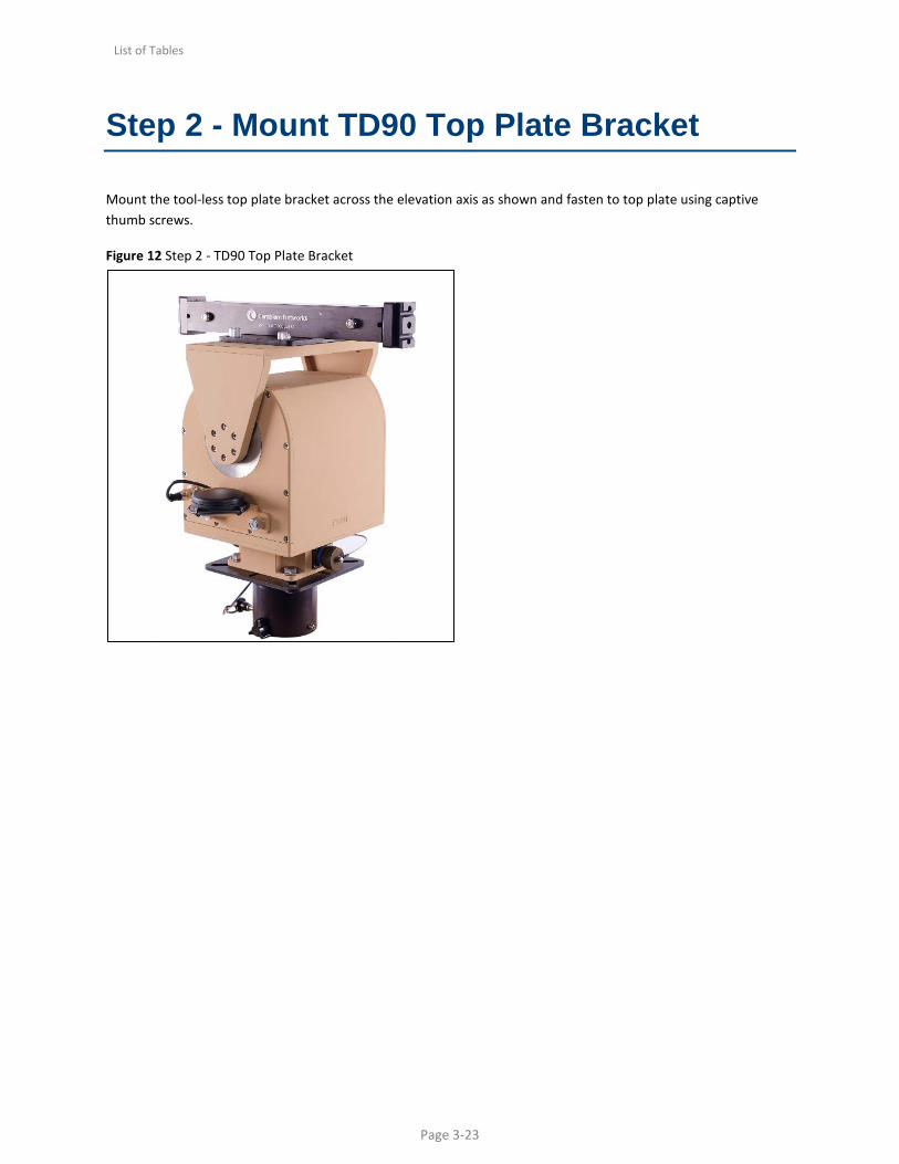
Step 2 - Mount TD90 Top Plate Bracket
Mount the tool-less top plate bracket across the elevation axis as shown and fasten to top plate using captive thumb screws.
Figure 12 Step 2 - TD90 Top Plate Bracket

List of Tables
Page 3-24
Step 3 - Mount PTP 700
PTP 700 with integrated Antenna Operation Slide the PTP 700 Radio and LPU plate bracket onto the TD90 Top Plate Bracket. Be sure to place the radio on the side marked “Front” and pin the radio to the bracket using the captive pin.
Figure 13 Step 3 - TD90 with TD90 Top Plate Bracket and PTP 700 mounted to front
PTP 700 with external Antenna Operation PTP 700 connectorized radio has two standard N-Type, which are used to connect external antenna.
Mount the PTP 700 to the TD90 Top Plate Bracket. Slide the PTP 700 Radio and LPU plate bracket onto the TD90 Top Plate Bracket. Be sure to place the radio on the side marked “Back” and pin the radio to the bracket using the captive pin.
Mount the 2’ parabolic antenna by using “C000000L082A PTP 700 Mast - Tactical mounting bracket - 2' Parabolic” to the TD90 Top Plate Bracket. Place the antenna on the side marked “Front” and pin the radio to the bracket using the captive pin.
Connect the RF cables between PTP 700 and external Antenna. V to V and H to H as marked on the PTP 700 and antenna.

List of Tables
Page 3-25
Step 4 - Connect Radio to TD90
Connect the PTP 700 Rugged LPU to the TD90 PSU Port using cable CK-CA16002A-WW.
Figure 14 Step 4 – PTP 700 to TD90
Typical PTP 700 to TD90 installations will utilize a Rugged Lighting Protection Unit (R-LPU). The R-LPU provides tactical tool-less installation, strain relief, and lightning protection. Configurations are available for Out-of– Band Management with Dual R-LPUs as well as operating with no LPU.
Insure proper cable to connect the TD90 to the PTP 700.
CK-CA16002A-WW

List of Tables
Page 3-26
Step 5 - Connect TD90 for operation
The following connections must be in place for proper operation.
1. Connection A: FROM PTP 700 to PSU (Completed in step 4)
2. Connection B:
a. TD90 Range cable FROM TD90 to Qty 2 Cambium Power Injector
b. Plug Breakout end of cable labeled “TD90” into Power Injector port labeled “ODU”
c. Plug Breakout end of cable labeled “PSU” into Power Injector port labeled “ODU”
d. (Note: Plug Cambium Networks Power Injectors into AC or DC source)
3. Connection C: FROM TD90 Power Injector port labeled “LAN” port to Ethernet switch
4. Connection D: FROM PSU Power Injector port labeled “LAN” port to Ethernet switch
5. Connection E: Connection E is optional for OoBM monitoring purposes from switch to laptop. If the TD90 and radio are configured properly then there is no need to connect a laptop for auto link establishment to take place. See TD90 Pre-Config instructions for more details.
Figure 15 Step 5 - From – To connection diagram
List of Tables
Page 3-27
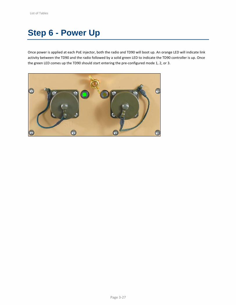
Step 6 - Power Up
Once power is applied at each PoE injector, both the radio and TD90 will boot up. An orange LED will indicate link activity between the TD90 and the radio followed by a solid green LED to indicate the TD90 controller is up. Once the green LED comes up the TD90 should start entering the pre-configured mode 1, 2, or 3.

List of Tables
Page 4-28
Chapter 4: TD90 Mechanical and Electrical Interfaces
The TD90 is a two-axis mechanical rotating positioner with an embedded controller that communicates with the radio and drives the antenna to automate the process of establishing the line of sight radio link. The TD90 requires some mechanical and electrical setup for this process to be successful. This section details the TD90 base mount and antenna mount surfaces along with identifying each connector, it’s purpose, and the individual pinouts.
List of Tables
Page 4-29
TD90 Base Mount Surface and Dimensions
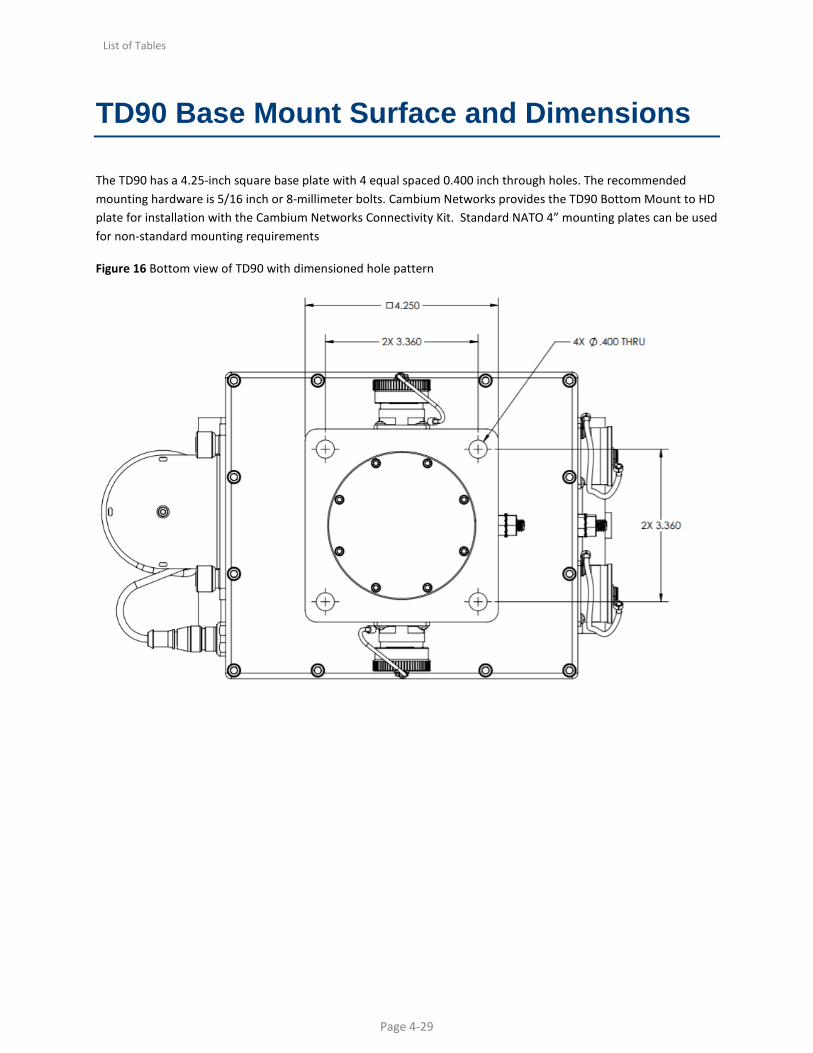
The TD90 has a 4.25-inch square base plate with 4 equal spaced 0.400 inch through holes. The recommended mounting hardware is 5/16 inch or 8-millimeter bolts. Cambium Networks provides the TD90 Bottom Mount to HD plate for installation with the Cambium Networks Connectivity Kit. Standard NATO 4” mounting plates can be used for non-standard mounting requirements
Figure 16 Bottom view of TD90 with dimensioned hole pattern

List of Tables
Page 4-30
Antenna Mount Surface and Dimensions
The TD90 has an 8.95 inch by 4.75-inch top plate with two-hole patterns and two alignment holes. The inner hole pattern with .250-20 threaded holes is most commonly used with the removable Cambium Networks TD90 Top Plate Bracket. The outer .312-18 threaded hole pattern provides a secondary mounting surface for future or non-standard antenna mount brackets.
Figure 17 Antenna mount surface with dimensioned hole pattern
List of Tables
Page 4-31
TD Interface Details
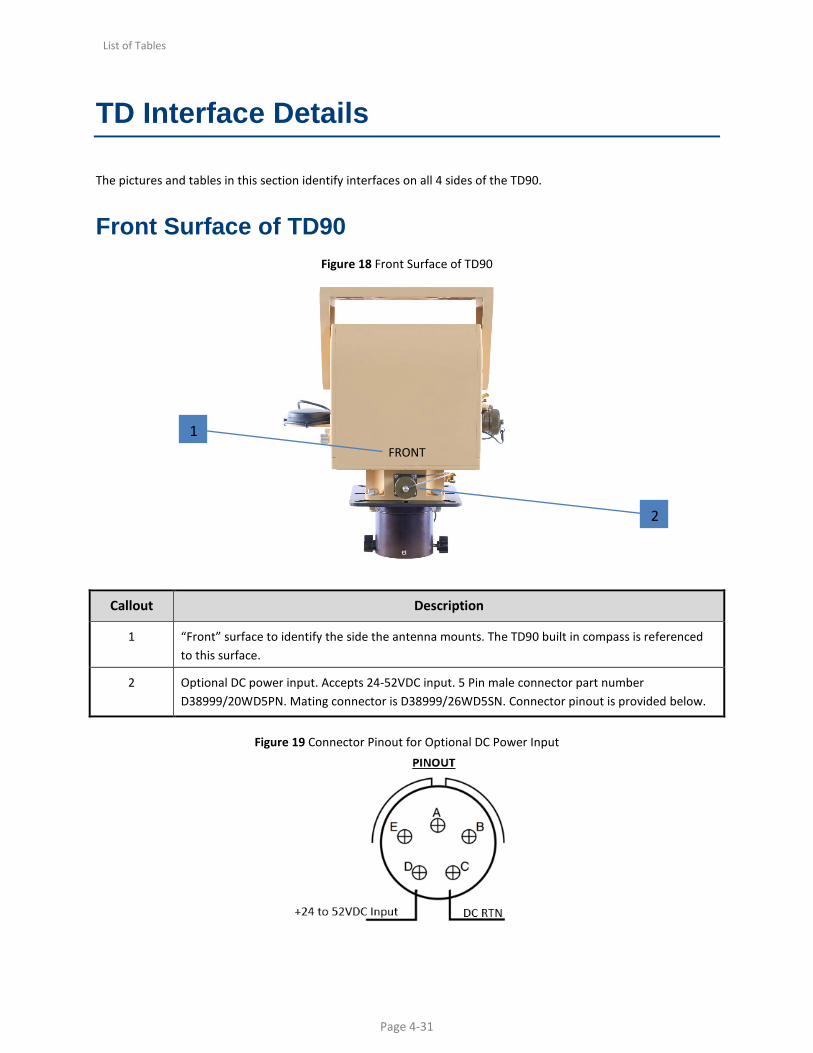
The pictures and tables in this section identify interfaces on all 4 sides of the TD90.
Front Surface of TD90 Figure 18 Front Surface of TD90
Callout Description
1 “Front” surface to identify the side the antenna mounts. The TD90 built in compass is referenced to this surface.
2 Optional DC power input. Accepts 24-52VDC input. 5 Pin male connector part number D38999/20WD5PN. Mating connector is D38999/26WD5SN. Connector pinout is provided below.
Figure 19 Connector Pinout for Optional DC Power Input
FRONT 1
2
List of Tables
Page 4-32
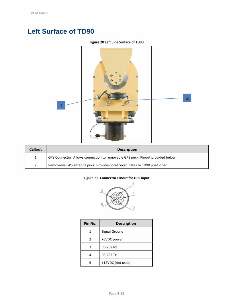
Left Surface of TD90 Figure 20 Left Side Surface of TD90
Callout Description
1 GPS Connector. Allows connection to removable GPS puck. Pinout provided below.
2 Removable GPS antenna puck. Provides local coordinates to TD90 positioner.
Figure 21 Connector Pinout for GPS input
Pin No. Description
1 Signal Ground
2 +5VDC power
3 RS-232 Rx
4 RS-232 Tx
5 +12VDC (not used)
1
2
List of Tables
Page 4-33
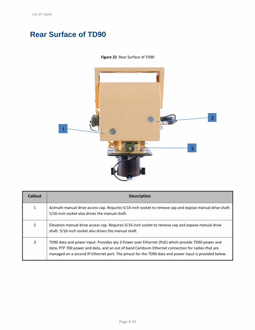
Rear Surface of TD90
Figure 22 Rear Surface of TD90
Callout Description
1 Azimuth manual drive access cap. Requires 5/16-inch socket to remove cap and expose manual drive shaft. 5/16-inch socket also drives the manual shaft.
2 Elevation manual drive access cap. Requires 5/16-inch socket to remove cap and expose manual drive shaft. 5/16-inch socket also drives the manual shaft.
3 TD90 data and power input. Provides qty 3 Power over Ethernet (PoE) which provide TD90 power and data, PTP 700 power and data, and an out of band Cambium Ethernet connection for radios that are managed on a second IP Ethernet port. The pinout for the TD90 data and power input is provided below.
1
2
3

List of Tables
Page 4-34
Figure 23 Connector Pinout for TD90 Data and Power input

List of Tables
Page 4-35
Right Side Surface of TD90 Figure 24 Right Side Surface of TD90
Callout Description
1 Upper ground stud. Above azimuth ¼-20-inch ground stud passes to below azimuth ¼-20-inch ground stud.
2 Power and Status LED indicator.
• Solid green = Power on and normal operation
• Slow blink(2Hz) = waiting for connection to radio
• Fast blink = Error
3 The PSU port is the Ethernet pass-thru connector for the PTP 700 that provides a connection point for the radio above the azimuth axis of rotation.
4 Link Activity LED. This indicator will come up first during the boot process and begin to blink to indicate Ethernet link activity between the TD90 and the Radio.
5 AUX port - Out of band Ethernet pass thru. Provides a secondary Ethernet connection to the PTP 700 for users that want to manage the radio on a secondary network.
1
5 3
2
4
6

List of Tables
Page 4-36
6 Lower ground stud. Below azimuth ¼-20-inch ground stud. Tied to upper ground stud and allows Earth ground connection from radio to be passed to the static side of the TD90.
Pass-through Pinouts for PSU Ethernet PSU Ethernet Pass-Through
(Sealed RJ-45) TD90 Data and Power
(37 Pin D38999) Description
1 23 Transmit +
2 8 Transmit +
3 24 Receive +
4 9 PoE 48-56VDC
5 25 PoE 48-56VDC
6 10 Receive -
7 26 PoE Rtn
8 11 PoE Rtn
Pass-through Pinouts for AUX Ethernet PSU Ethernet Pass-Through
(Sealed RJ-45) TD90 Data and Power
(37 Pin D38999) Description
1 17 Transmit +
2 30 Transmit +
3 16 Receive +
4 29 PoE 48-56VDC
5 15 PoE 48-56VDC
6 28 Receive -

List of Tables
Page 4-37
7 14 PoE Rtn
8 27 PoE Rtn

List of Tables
Page 5-38
Chapter 5: Web Based User Interface
The Cambium Networks TD90 Web based user interface provides control and status pages for a user to pre-configure the system for operation, monitor the system status, and/or perform manual control of the system. This section provides screen shots and details the six available controls or status pages on the TD90 user interface.

List of Tables
Page 5-39
TD90 Home
The TD90 Home page is the default launch page. The default IP address assigned to a TD90 is 169.254.1.245. The callout’s below point to the various controls and status provided on the home page and are described in the table below.
1
2
3
4
5
6
7
8

List of Tables
Page 5-40
Callout Description
1 Default IP address for Cambium TD90. IP address may be changed on the Setup page.
2 Displays the current software revision loaded on the TD90 embedded controller.
3 The “STOP” button will appear when the system is in a “Run” state. Clicking over the “STOP” button stop the TD90 from moving. If the “STOP” button is pressed it will be replaced with the “RUN” button (shown below). The “RUN” button places the TD90 back into operation. The positioner will also default back to run with a power cycle.
4 The “Stow” button will move the positioner to the predetermined stow position. The default stow location is 0° Azimuth and 0° Elevation. The stow location may be changed on the positioner config page.
5 Page select menu. Default is Home. The blue bar indicates the current page. Press over and highlight the “Home” “Setup” “Manual Control” “Positioner Config” “Compass” or “Errors” page to navigate between pages.
6 “Reboot” button. The Reboot button forces the TD90 to reboot the on-board control software.
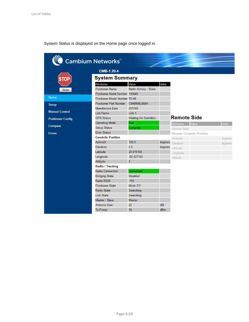
7 The System Summary Table provides status of the TD90 positioner, Orientation, and Radio and Tracking status. A separate table is provided below with additional details on the System summary table.
8 The Remote Side table is only active when a radio link is established. The remote side table provides details of the TD90 and radio on the opposite end of the link. A separate table is provided below with additional details on the Remote Side table.

List of Tables
Page 5-41
Table 1 Home page descriptions
Attributes Description
Positioner Name TD90 positioner may be named to identify as a unique name. The TD90 may be named under the Positioner Config page under “Unit Name”.
Positioner Serial Number Identifies the unique serial number assigned to the TD90.
Link Name This field is populated by the PTP 700 and will display the link name assigned to the radio.
GPS Status Provides connection status to the GPS puck.
Operating Mode Provides the current operating mode of the TD90.
Setup Status Provides status of the setup page. The status will read “Complete” if a minimum of a Radio IP address is entered.
Error Status Display’s an error code should the unit enter an error state. Error status is also visually displayed on the “Errors” page.
Geodetic Position
Azimuth Displays the TD90’s Azimuth angle is Geodetic frame which is the TD90’s Azimuth with reference to true north.
Elevation Displays the TD90’s Elevation angle with reference to Geodetic frame (±30 from Horizon).
Latitude Displays current angular distance North or South of the earths equator. North of equator = Positive and South of equator = Negative.
Longitude Displays current angular distance east or west of the meridian at Greenwich UK.
Altitude Distance in meters above sea level
Radio / Tracking
Radio Connection Provides radio connection status between the local TD90 and its radio “Disconnected” or “Connected”.
Bridging State Enabled or Disabled, provides status of Data bridge between radio pair.
Radio RSSI Provides current signal strength of the local side radio.
Positioner State Current mode or operation the local TD90 is in. Examples would be mode 1, 2/3, or Seek, Peak, etc.
Radio State Current status of local TD90 radio. Acquiring, searching, or Registering.
Link State Current status of radio link (pair of radios)
Master/Slave Indicates if the TD90 is connected to the Master or Slave Radio. The TD90 is assigned the Master or Slave positioner based on the radio installed on the positioner.

List of Tables
Page 5-42
Attributes Description
Antenna Gain Provides antenna gain of antenna attached. This information is pulled off of the radio attached to the TD90.
Tx Power Displays current Tx power the PTP 700 is transmitting.
Attributes Description
Remote State Remote side status of TD90 positioner state.
Remote Geodetic Position
Azimuth Displays the remote side TD90’s Azimuth angle is Geodetic frame which is the TD90’s Azimuth with reference to true north.
Elevation Displays the remote side TD90’s Elevation angle with reference to Geodetic frame (±30 from Horizon).
Latitude Displays the remote side TD90 current angular distance North or South of the earths equator. North of equator = Positive and South of equator = Negative.
Longitude Displays the remote side TD90 current angular distance east or west of the meridian at Greenwich UK.
Altitude Displays the remote side TD90 distance in meters above sea level.
List of Tables
Page 5-43
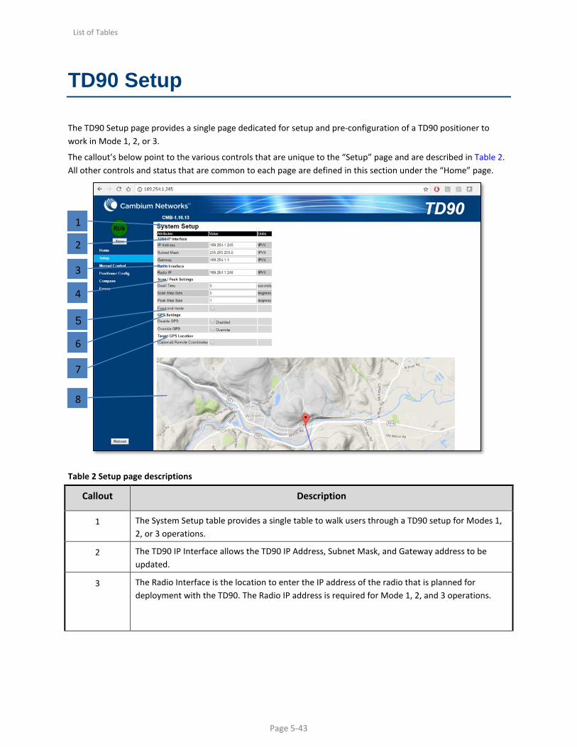
TD90 Setup
The TD90 Setup page provides a single page dedicated for setup and pre-configuration of a TD90 positioner to work in Mode 1, 2, or 3.
The callout’s below point to the various controls that are unique to the “Setup” page and are described in Table 2. All other controls and status that are common to each page are defined in this section under the “Home” page.
Table 2 Setup page descriptions
Callout Description
1 The System Setup table provides a single table to walk users through a TD90 setup for Modes 1, 2, or 3 operations.
2 The TD90 IP Interface allows the TD90 IP Address, Subnet Mask, and Gateway address to be updated.
3 The Radio Interface is the location to enter the IP address of the radio that is planned for deployment with the TD90. The Radio IP address is required for Mode 1, 2, and 3 operations.
2
1
3
4
5
6
8
7
List of Tables
Page 5-44
Callout Description
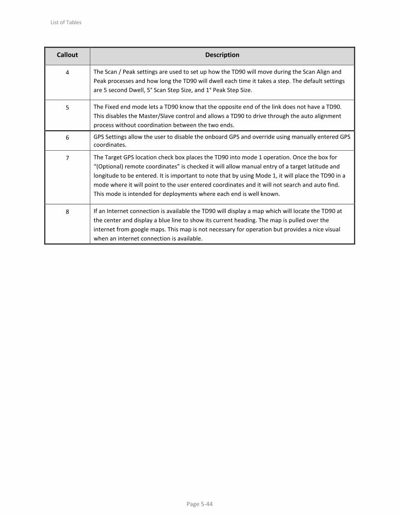
4 The Scan / Peak settings are used to set up how the TD90 will move during the Scan Align and Peak processes and how long the TD90 will dwell each time it takes a step. The default settings are 5 second Dwell, 5° Scan Step Size, and 1° Peak Step Size.
5 The Fixed end mode lets a TD90 know that the opposite end of the link does not have a TD90. This disables the Master/Slave control and allows a TD90 to drive through the auto alignment process without coordination between the two ends.
6 GPS Settings allow the user to disable the onboard GPS and override using manually entered GPS coordinates.
7 The Target GPS location check box places the TD90 into mode 1 operation. Once the box for “(Optional) remote coordinates” is checked it will allow manual entry of a target latitude and longitude to be entered. It is important to note that by using Mode 1, it will place the TD90 in a mode where it will point to the user entered coordinates and it will not search and auto find. This mode is intended for deployments where each end is well known.
8 If an Internet connection is available the TD90 will display a map which will locate the TD90 at the center and display a blue line to show its current heading. The map is pulled over the internet from google maps. This map is not necessary for operation but provides a nice visual when an internet connection is available.

List of Tables
Page 5-45
TD90 Manual Control
The TD90 Manual Control page provides a tool to manually move a TD90 positioner by slewing around or commanding to a specific azimuth and elevation.
The callout’s below point to the various controls that are unique to the “Manual Control” page and are described in Table 3. All other controls and status that are common to each page are defined in this section under the “Home” page.
1
2
3
4
5

List of Tables
Page 5-46
Table 3 Manual control page descriptions
Callout Description
1 The Slew Controls allow a user to slew a TD90 Up, Down, Left, or Right using the arrow buttons.
2 The Geodetic position displays the Azimuth and Elevation with reference to True North = 0 Azimuth and Horizon = 0 Elevation.
3 The Pedestal position displays the pedestal angles with reference to the TD90 center of travel in both axis = to 0
4 Set Pedestal Angles allows a user to manually enter in a commanded Azimuth and Elevation angle and press “Go” to execute. The command angle is always in pedestal coordinates but displayed in both Geo and Pedestal frame.
5 The Peaking indicator displays the radios current Receive Signal Strength Indication (RSSI) if a local connection between the radio and the TD90 is in place.

List of Tables
Page 5-47
TD90 Positioner Configuration
The TD90 Positioner Config page provides a tool to set TD90 positioner configuration items such as pedestal limits, stow position, orientation of installation, and unit name. It also allows updates of TD90 software when new software updates are available.
The callout’s below point to the various controls that are unique to the “Positioner Config” page and are described in Table 4. All other controls and status that are common to each page are defined in this section under the “Home” page.
Table 4 Positioner control page descriptions
Callout Description
1 The Limits are set to default maximum travel range a TD90 do (Shown above ±200° Azimuth and ±30° Elevation). The user may limit the travel range within this Azimuth or Elevation range.
2 The stow position is default to 0 degrees azimuth and 0 degrees elevation. The unit will move to the user entered preset when the “Stow” button is pushed on any of the TD90 control pages.
1
2
3
4
5

List of Tables
Page 5-48
Callout Description
3 The orientation of normal operation is elevation over azimuth as shown throughout this manual. If the end user has deployment scenarios where the TD90 must be mounted upside down (Inverted) then the inverted check box should be checked.
4 Unit Name allows the TD90 to be given a unique name that will display on the home system summary page under “Positioner name” if left blank the positioner name will remain blank.
5 The Software upload allows for upgrades to the software when available.
List of Tables
Page 5-49
TD90 Compass
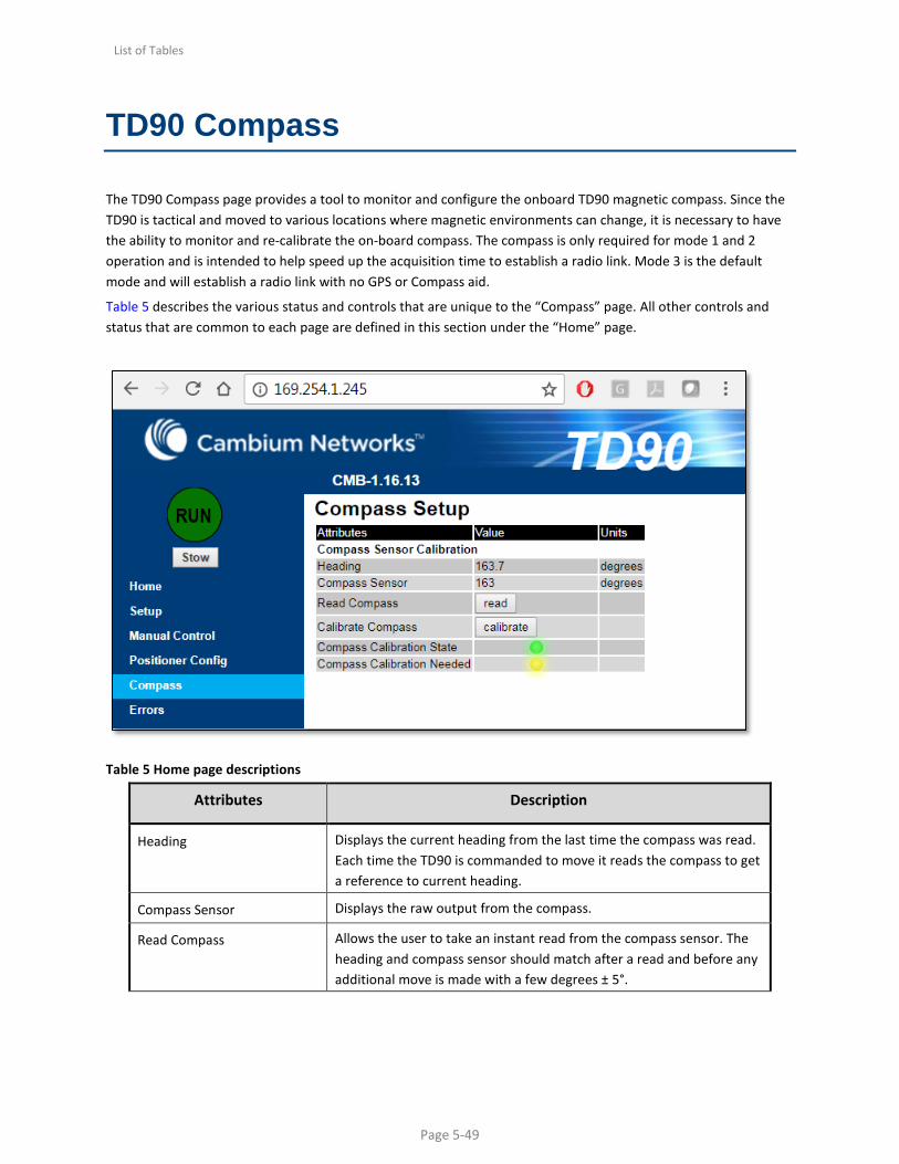
The TD90 Compass page provides a tool to monitor and configure the onboard TD90 magnetic compass. Since the TD90 is tactical and moved to various locations where magnetic environments can change, it is necessary to have the ability to monitor and re-calibrate the on-board compass. The compass is only required for mode 1 and 2 operation and is intended to help speed up the acquisition time to establish a radio link. Mode 3 is the default mode and will establish a radio link with no GPS or Compass aid.
Table 5 describes the various status and controls that are unique to the “Compass” page. All other controls and status that are common to each page are defined in this section under the “Home” page.
Table 5 Home page descriptions
Attributes Description
Heading Displays the current heading from the last time the compass was read. Each time the TD90 is commanded to move it reads the compass to get a reference to current heading.
Compass Sensor Displays the raw output from the compass.
Read Compass Allows the user to take an instant read from the compass sensor. The heading and compass sensor should match after a read and before any additional move is made with a few degrees ± 5°.

List of Tables
Page 5-50
Attributes Description
Calibrate Compass Allows the user to re-calibrate the compass. The positioner should be located in its installed location with all attachments made before re-calibrating is performed.
Compass Calibration State A green LED will indicate that the compass has been calibrated. If the LED turns red this will indicate that compass is no longer operating in a stable magnetic environment.
Compass Calibration Needed The compass calibration needed LED will change between yellow and green states. Green = good while Yellow suggests the need for a compass calibration. This tool is monitoring the embedded magnetometer and has expected vector lengths that indicate normal operation as it travels through a 360 rotation. If these lengths grow beyond a certain level of unbalance the calibration needed LED will switch to yellow.

List of Tables
Page 5-51
TD90 Errors
The TD90 Errors page provides a window to monitor error conditions that may happen during the acquisition process. An error indicator does not necessary indicate the TD90 will not establish a link buy may explain why the TD90 will take longer to acquire or switch acquisition modes.
Table 6 describes the Error Conditions alarms that are unique to the “Errors” page. All other controls and status that are common to each page are defined in this section under the “Home” page.
List of Tables
Page 5-52
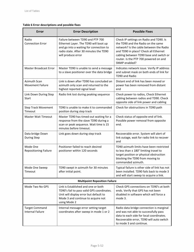
Table 6 Error descriptions and possible fixes
Error Error Description Possible Fixes
Radio Connection Error
Failure between TD90 and PTP 700 Ethernet Layer. The TD90 will boot up and go into a waiting for connection to radio state. After 30 minutes the TD90 will produce error
Check IP settings on Radio and TD90. Is the TD90 and the Radio on the same network? Is the cable between the Radio and TD90 in place? Check all Ethernet cabling between TD90 base and switch or router. Is the PTP 700 powered on and SNMP enabled?
Master Broadcast Error Master TD90 is unable to send a message to a slave positioner over the data bridge
Indicates network issue. Verify IP address and subnet mask on both ends of link for TD90 and Radio
Azimuth Scan Movement Failure
Link is down after TD90 has concluded an azimuth only scan and returned to the highest reported signal level
Distant end of link has been moved or power has been removed from distant end
Link Down During Step Start
Radio link lost during peaking sequence Check power to radios, Check Ethernet cabling between radios and TD90. Check opposite side of link power and cabling
Step Track Movement Timeout
TD90 is unable to make it to commanded position during step track
Check for obstructions in TD90 path
Master Wait Timeout Master TD90 has timed-out waiting for a response from the slave TD90 during a scan or peak sequence. Wait time is 15 minutes before timeout.
Check status of opposite end of link. Possible power removal from opposite end.
Data bridge Down During Step
Link goes down during step track Recoverable error. System will alert of link outage, wait for radio link to recover and
Mode One Repositioning Failure
Positioner failed to reach desired positioner within 120 seconds
TD90 azimuth limits have been restricted to less than ± 180° limiting travel to target position or physical obstruction blocking the TD90 from moving to commanded azimuth.
Mode One Sweep Timeout
TD90 swept in azimuth for 30 minutes after initial point.
Typical failure is other side of link has not been installed. TD90 fails back to mode 3 and will start sweep to acquire a link.
Multipoint Reposition Failure
Mode Two No GPS Link is Established and one or both TD90’s fail to pass valid GPS coordinates. Unit will display error but default to Mode 3 and continue to acquire not using Mode 2
Check GPS connections on TD90’s at both ends. Verify that GPS has not been disabled in software which will force a mode 3.
Target Command Internal Failure
Internal message error setting target coordinates after sweep in mode 1 or 2
Radio data bridge connection is marginal and was not able to successfully pass data to each side for local coordinates. Recoverable error, TD90 will auto switch to mode 3 and continue.

List of Tables
Page 5-53
Error Error Description Possible Fixes
Mode Two Reposition Failure
Positioner failed to reach desired positioner within 120 seconds
TD90 azimuth limits have been restricted to less than ± 180° limiting travel to target position or physical obstruction blocking the TD90 from moving to commanded azimuth.
Mode One/Two Compass Calibration
Compass monitoring tool indicating compass requires re-calibration
Navigate to compass page and re-calibrate compass
Sweep Timeout Error TD90 has been sweeping in azimuth for 1 hour with no link activity.
Suggests there is no other PTP 700 on air to form a link. Check setup status of opposite side and cycle power to restart process.
Link Down Scan Start Error
TD90 stops moving immediately after any link is established during the initial sweep. The Link down at scan start indicates the link is interrupted after the sweep but before the first scan starts.
Indicates marginal link at stop of sweep process. Recoverable error as TD90 will return to sweep process.
Az Scan Move Timeout Error
Positioner failed to reach its desired azimuth within 60 seconds while performing an azimuth only scan
Check for obstructions and verify if the commanded position exceeded pre-set TD90 limits
Step Track Movement Failure
Positioner failed to move during a step-track
Check for obstructions and verify if the commanded position exceeded pre-set TD90 limits
Data Bridge Down During Scan
Slave Wait Timeout Slave positioner has timed-out waiting for a command from the master to perform a scan or peak function. Timeout period is 15 minutes.
Recoverable. Typical root cause is PTP 700 reboot.
Radio Disconnected Connection between TD90 and Radio is lost
Check Ethernet cabling between radio and TD90. Check power on Radio
Mode One Control Problem
Mode control process failed to switch to pointing mode
Recoverable error. Possible error in manual entry of GPS Coordinates. Check TD90 stored target location coordinates. TD90 will default to Mode 3.
Mode one Data bridge Drop
In mode 1, the data bridge drops after it has been established but before the scan and peak process.
Recoverable error. Indicates excessive compass or GPS error. TD90 will default to Mode 3
Multipoint Mode Control Failure
Location Exchange Error
TD90 A and B sides failed to exchange local coordinates within the 20 second time limit
Suggests marginal link during initial sweep process. Recoverable error, TD90 reverts to Mode 3.
Sweep Mode Control Failure
TD90 fails to enter sweep mode Indicates blockage or motor drive failure. Cycle power

List of Tables
Page 5-54
Error Error Description Possible Fixes
Mode Two Data bridge Dropped
TD90 selects mode 2 and exchanges coordinate locations on both ends. TD90’s both points using on board compass. It is assumed a data bridge will be active after the aid of GPS and compass pointing. If not bridge exists, the system will default back to mode 3 to establish link.
Recoverable error. Suggests that GPS or Compass may be compromised. Verify accuracy of GPS coordinates on both ends and compass heading. May require compass calibration on one or both ends.

List of Tables
Page 6-55
Chapter 6: Setup Validation and Troubleshooting
A Proper setup will help avoid troubleshooting. The following sections describe how setup can be accomplished to insure the system is working properly.
• Connecting to PTP 700
• Verify Settings for each device
• Connecting to TD90
• Verify Settings for each device
• Connecting TD90 to PTP 700
• Troubleshooting TD90 to PTP 700 operation
• Over the Air connection between locations

List of Tables
Page 6-56
Testing Connection to PTP 700
It is important to insure configuration of the PTP 700 radio is correct and can support the use of a TD90 antenna positioning system. The following steps will describe and guide the operator through the process. Verify that the management laptop can connect to the PTP 700 radio. Verify IP address on management station laptop
o See Figure 2 on page 2-9 Setup new PTP 700 Radio steps
o See PTP 700 MLOS Connectivity Kit QRG (Quick Reference Guide) for complete system hardware setup instructions
o Apply Power o Ping the PTP 700 radio o Login to default IP
169.254.1.1 255.255.0.0
o Configure for operation Link Setup See PTP 700 Users Guide for complete radio setup instructions Make sure the PTP 700 and TD90 are in same subnet
o Setup SNMPv2c • Ping the PTP 700
o At Command Prompt type the following o C:\>Ping –t 169.254.1.1
List of Tables
Page 6-57
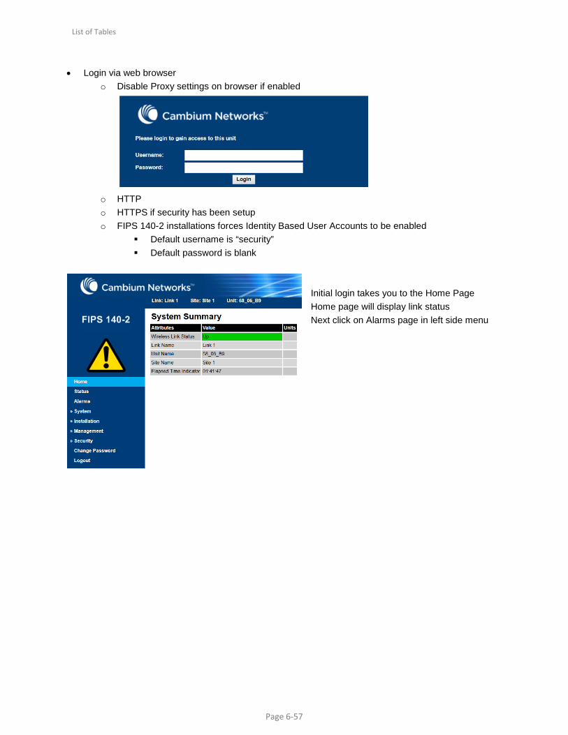
• Login via web browser o Disable Proxy settings on browser if enabled
o HTTP o HTTPS if security has been setup o FIPS 140-2 installations forces Identity Based User Accounts to be enabled
Default username is “security” Default password is blank
Initial login takes you to the Home Page Home page will display link status Next click on Alarms page in left side menu

List of Tables
Page 6-58
Alarm page will display link errors and alarms Next Click on Installation page in left side menu
Installation page displays the systems current configuration

List of Tables
Page 6-59
Installation Page Continued Scroll to the bottom of the page Click Continue to Installation Wizard button
List of Tables
Page 6-60
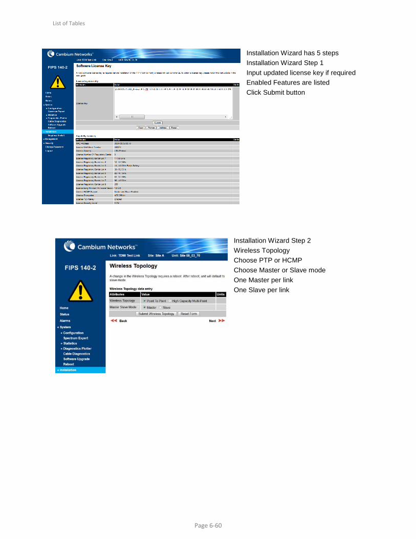
Installation Wizard has 5 steps Installation Wizard Step 1 Input updated license key if required Enabled Features are listed Click Submit button
Installation Wizard Step 2 Wireless Topology Choose PTP or HCMP Choose Master or Slave mode One Master per link One Slave per link

List of Tables
Page 6-61
Installation Wizard Step 3 Interface Configuration Click Submit or Next button
Installation Wizard Step 4 Wireless Configuration Everything must match at both ends of link
Installation Wizard Step 4 continued Wireless Configuration Insure to “Arm” the radio for best results with TD90. With or Without tones based on operator preference Click Submit button

List of Tables
Page 6-62
Installation Wizard Step 5 Confirm all settings are correct Installation Wizard Step 5 Continued Changes made will be in BOLD print Click Submit button Click confirm to reboot wireless unit
List of Tables
Page 6-63
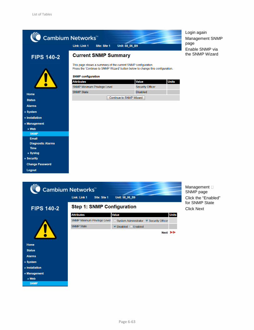
Login again Management SNMP page Enable SNMP via the SNMP Wizard Management SNMP page Click the “Enabled” for SNMP State Click Next

List of Tables
Page 6-64
• Management SNMP page – For TD90 operation choose SNMP version 2c – Click Next
Management SNMP page Enter optional information Click Next

List of Tables
Page 6-65
Management SNMP page Disable all traps Click Next
SW versions match at both ends of link Region Code match at both ends of link
List of Tables
Page 6-66
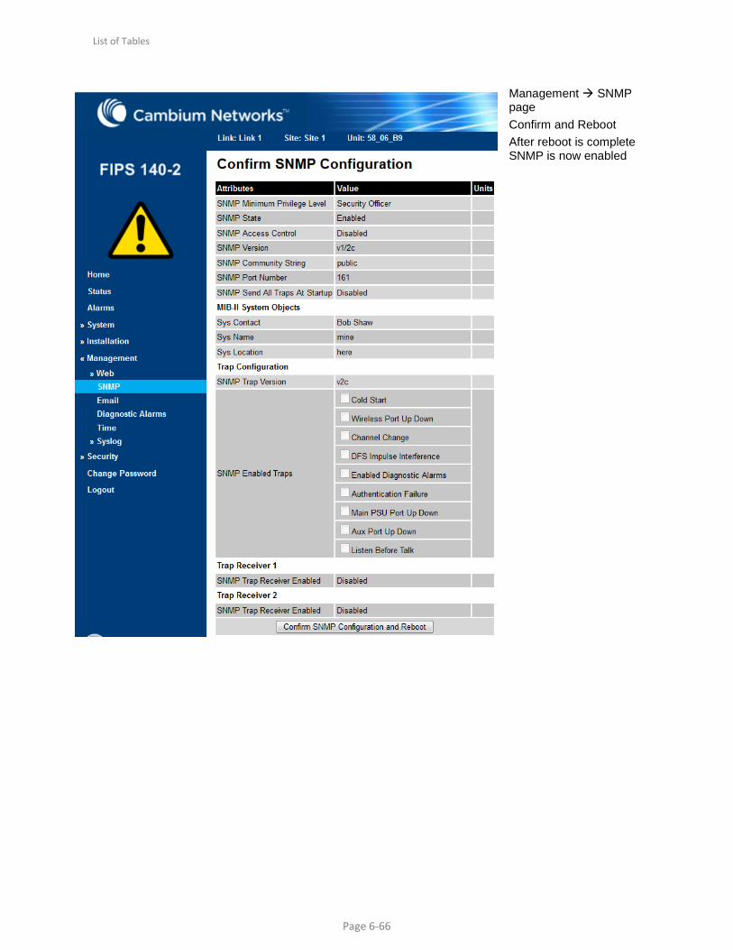
Management SNMP page Confirm and Reboot After reboot is complete SNMP is now enabled

List of Tables
Page 6-67
Status page will display link status
• Refer to the “Recovery Mode” in PTP 700 Users Guide on how to recover a radio that has an unknown IP Address or Username/password is unknown.
• Refer to “Cable Diagnostics” in PTP 700 Users Guide on how to perform cable diagnostics test to detect cabling related faults.
• Refer to “Testing link end hardware” in PTP 700 Users Guide describes how to test the link end hardware, either when it fails on startup, or after a lightning strike.
List of Tables
Page 6-68
Testing Connection to TD90
It is important to insure configuration of the TD90 is correct and can support use with the PTP 700 radio. The following steps will describe and guide the operator through the process. Verify that the management laptop can connect to the TD90 radio. Verify IP address on management station laptop
o See Figure 2 on page 2-9
See PTP 700 MLOS Connectivity Kit QRG (Quick Reference Guide) for complete system hardware setup instructions
Apply Power Ping TD90 Login to default IP
169.254.1.245 255.255.0.0
Configure for operation Setup
Make sure the PTP 700 and TD90 are in same subnet Positioner Configuration Compass Calibration
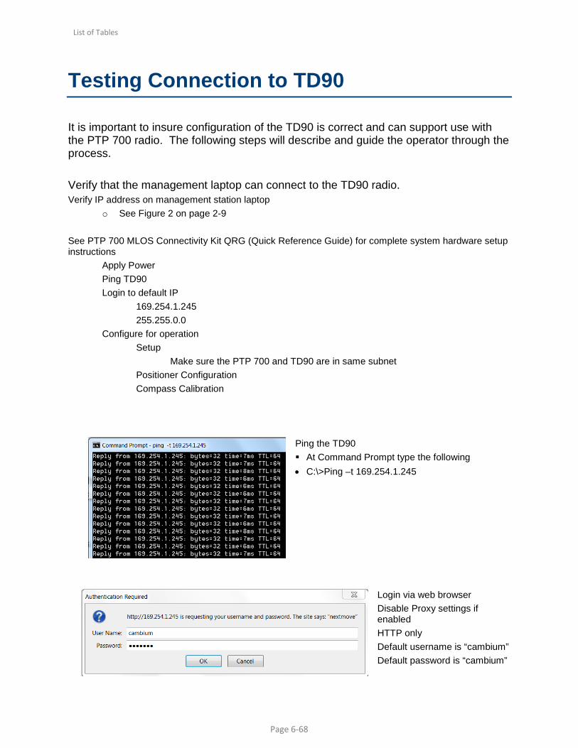
Ping the TD90 At Command Prompt type the following • C:\>Ping –t 169.254.1.245
Login via web browser Disable Proxy settings if enabled HTTP only Default username is “cambium” Default password is “cambium”
List of Tables
Page 6-69
System Status is displayed on the Home page once logged in.

List of Tables
Page 6-70
Configure TD90 IP Interface IP Address Subnet Mask Gateway Configure Paired PTP700 IP Address
Scan / Peak Settings Scan / Peak settings are optimized
for PTP 700 Integrated and 2’ (0.6m) parabolic antennas
Leave as default unless 3’ or larger antenna is used
Fixed Mode – check when TD90 is at one end of link only
GPS Settings Leave as default unless you are positive of location information and fidelity of GPS Data Target GPS Location Leave as default unless you now and are positive of remote site information and fidelity of GPS Data
The Google Map data will display If GPS Data is available and you are connected to the Internet
List of Tables
Page 6-71
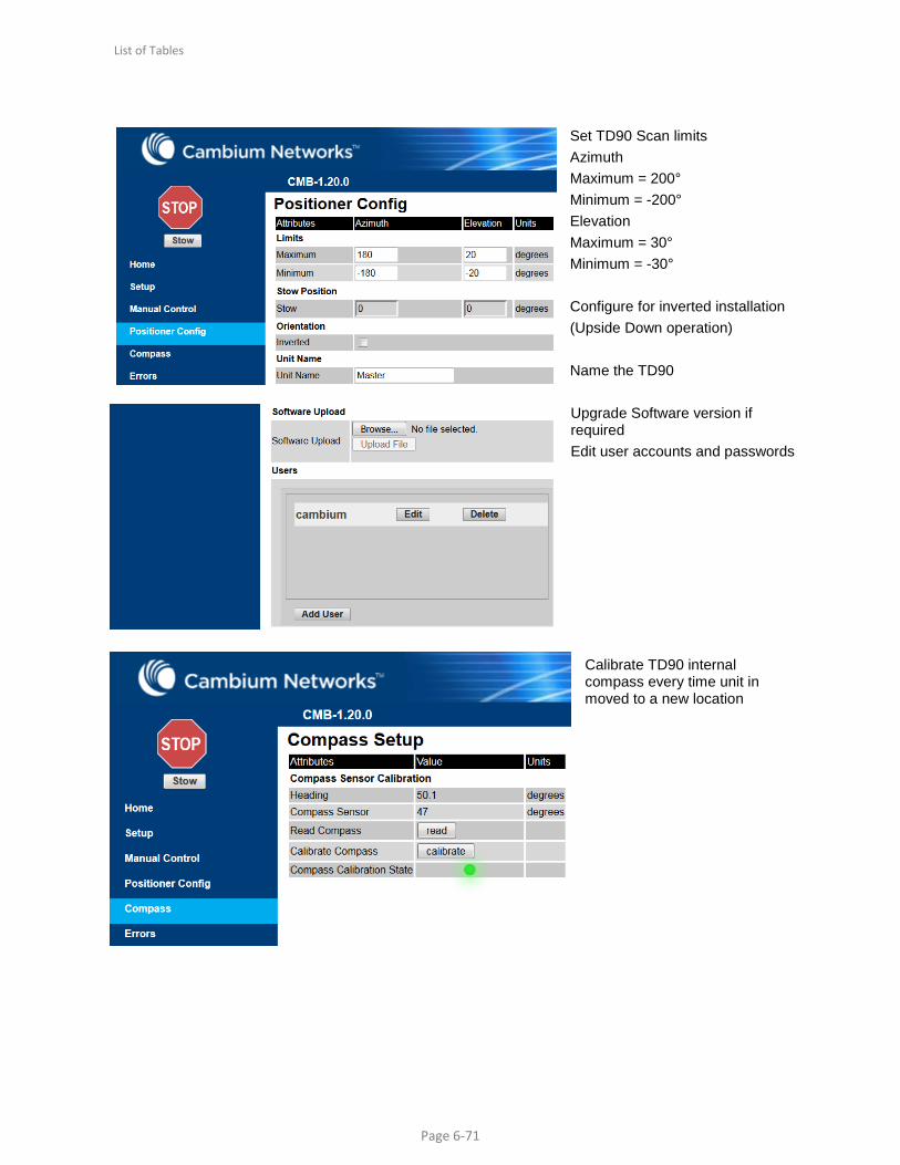
Set TD90 Scan limits Azimuth Maximum = 200° Minimum = -200° Elevation Maximum = 30° Minimum = -30° Configure for inverted installation (Upside Down operation) Name the TD90 Upgrade Software version if required Edit user accounts and passwords
Calibrate TD90 internal compass every time unit in moved to a new location
List of Tables
Page 6-72
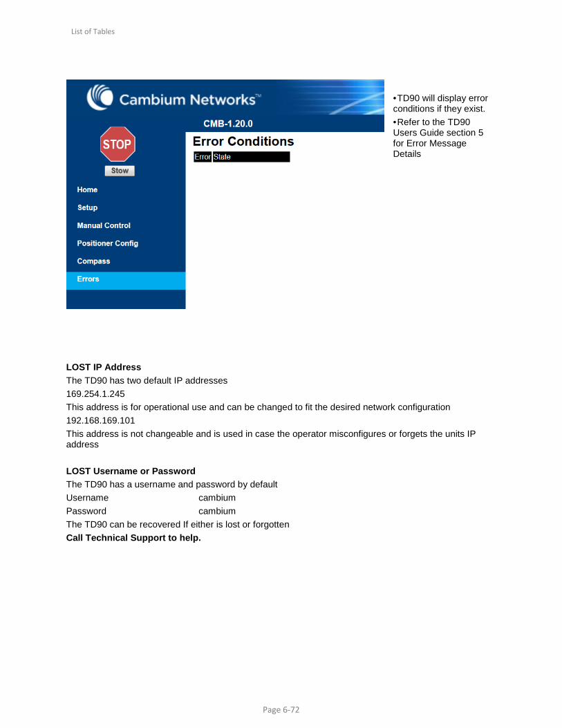
• TD90 will display error conditions if they exist. • Refer to the TD90 Users Guide section 5 for Error Message Details
LOST IP Address The TD90 has two default IP addresses 169.254.1.245 This address is for operational use and can be changed to fit the desired network configuration 192.168.169.101 This address is not changeable and is used in case the operator misconfigures or forgets the units IP address LOST Username or Password The TD90 has a username and password by default Username cambium Password cambium The TD90 can be recovered If either is lost or forgotten Call Technical Support to help.
List of Tables
Page 6-73
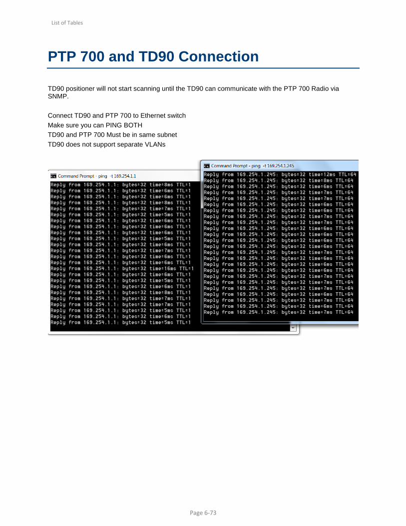
PTP 700 and TD90 Connection
TD90 positioner will not start scanning until the TD90 can communicate with the PTP 700 Radio via SNMP. Connect TD90 and PTP 700 to Ethernet switch Make sure you can PING BOTH TD90 and PTP 700 Must be in same subnet TD90 does not support separate VLANs

List of Tables
Page 6-74
Check to see if Green light on TD90 is solid and not blinking
Verify TD90 is able to communicate with PTP 700 Radio Home page displays Radio Connection as “Connected” Master / Slave status is displayed Antenna Gain is displayed Transmitter Power for PTP 700 (Tx) is displayed

List of Tables
Page 6-75
Troubleshooting Connectivity between PTP 700 and TD90
Test and verify TD90 and PTP 700 can see each other by connecting to common Ethernet Switch capable of carrying untagged Ethernet traffic between TD90 and PTP 700 Three parameters must be correct for TD90 operation with a PTP 700 radio TD90 setting for IP Address of PTP 700 must be correct SNMP must be enabled on the PTP 700 radio PTP 700 radios must be programmed correctly for link operation Four parameters must match for PTP 700 links to connect AES Over the Air Encryption must match exactly Software Versions must match exactly Regulatory Band must match exactly Installation Page settings must match exactly – (Except Master/Slave)

List of Tables
Page 6-76
Connected shows TD90 and PTP 700 are connected
AES Encryption Type MUST MATCH At BOTH ENDS
List of Tables
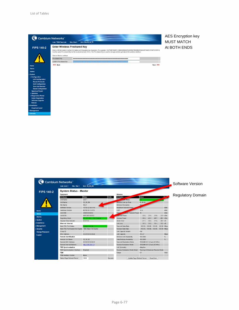
Page 6-77
AES Encryption key MUST MATCH At BOTH ENDS
Software Version Regulatory Domain

List of Tables
Page 6-78
Installation Wizard MUST MATCH At BOTH ENDS Except only one Master and one Slave

List of Tables
Page 6-79
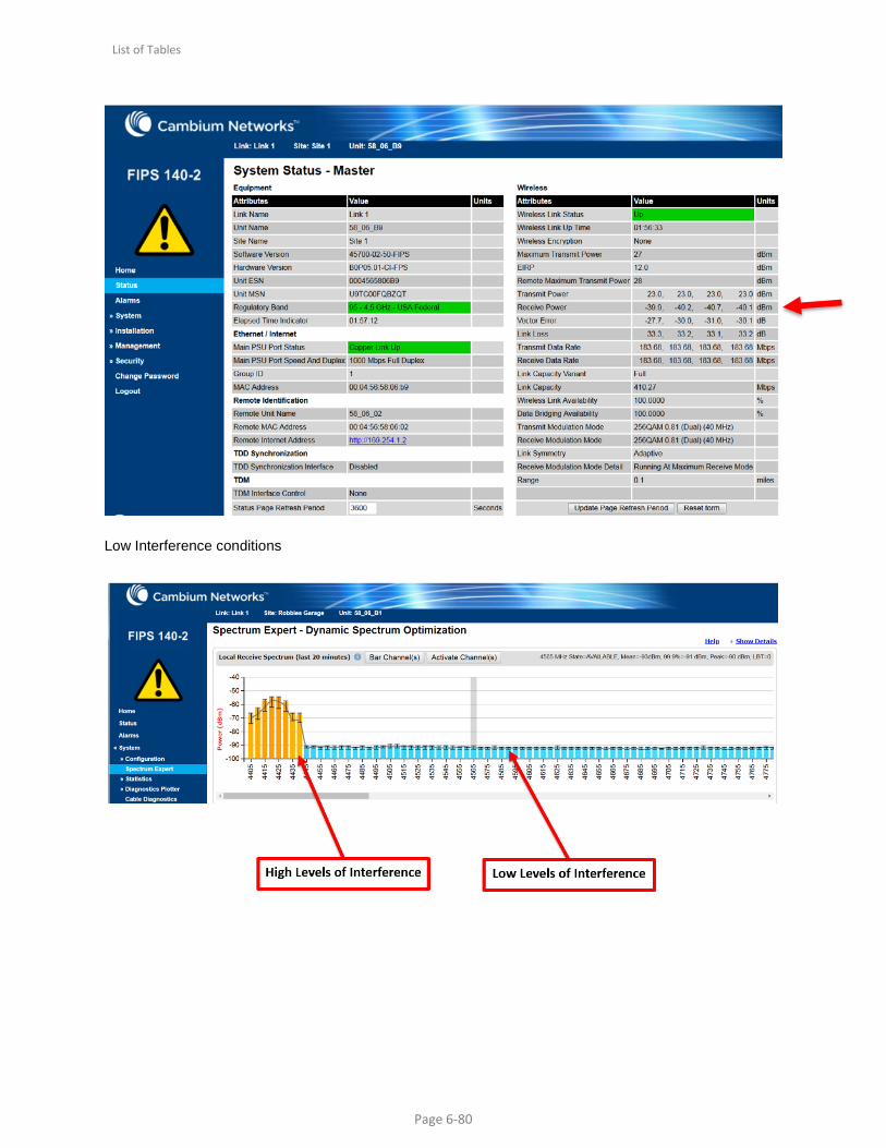
Over the Air Connectivity of PTP 700 Link
Refer to the PTP 700 Users Guide for complete information on PTP 700 Operation and troubleshooting RF path conditions must meet minimum PTP 700 radio levels to acquire a link. Most common issue is Signal Levels is too low Next is High Levels of external Interference Rx Power > -83 dBm for minimum link operation. Strive to install PTP 700 where there is the least amount of obstructions. Line of Sight is preferred. The PTP 700 can reliably communicate over long distances at high throughput. It is important that the Over the Air link be optimized Receive Power must be greater than -83 dBm. More is better -45 dBm Receive Power is optimal if possible
TD90 automatically aligns the link to best possible signal Care should be taken to position the ends of the link to allow for the least amount of obstructions possible. Line of Sight is optimal. Finding a clear RF channel is also required. Interference levels 40 dB lower than the receive power signal are most optimal. Example Receive Power = -40 dBm Clean channel should be -80 dBm Disarm Installation Agent once link is optimized for highest possible throughput.
List of Tables
Page 6-80
Low Interference conditions