USER GUIDE ENTER - images-na.ssl-images … GUIDE ENTER. HYDRO TECH PERFORMANCE MONITOR ......
42
USER GUIDE ENTER
Transcript of USER GUIDE ENTER - images-na.ssl-images … GUIDE ENTER. HYDRO TECH PERFORMANCE MONITOR ......

USER GUIDE
ENTER

HYDRO TECH PERFORMANCE MONITOR ADVANCED F ILTRAT ION SYSTEMwww. f luva l - g .com
IMPORTANT SAFETY INSTRUCTIONSWARNING - To guard against injury, basic safety precautions should be observed.
READ AND FOLLOW ALL SAFETY INSTRUCTIONSTo guard against injury, basic safety precautions should be observed when handling the Fluval Canister Filter, including the following:
1. READ AND FOLLOW ALL SAFETY INSTRUCTIONS and all the important notices on the appliance before using. Failure to do so may result in damage to the unit.
2. DANGER – To avoid possible electric shock, special care should be taken since water is employed in the use of aquarium equipment. For each of the following situations, do not attempt repairs yourself; return the appliance to an authorized service facility for service or discard the appliance. A. If the appliance falls into the water, DON’T reach for it! First unplug it and retrieve it. If electrical components of the appliance get wet, unplug the appliance immediately.
B. If the appliance shows any sign of abnormal water leakage or if RCD (or GFCI- Ground Fault Current Interrupter) switches off disconnect the power supply cord from mains and remove pump from water.
C. Carefully examine the appliance after installation. It should not be plugged if there is water on parts not intended to be wet.
D. Do not operate any appliance if it has a damaged cord or plug, or if it is malfunctioning or it is dropped or damaged in any manner. The power cord of this appliance cannot be replaced; if the cord is damaged, the appliance should be discarded. Never cut the cord. The display label of this appliance cannot be replaced; if the display label is damaged or not fully adherent, the appliance should be discarded.
E. To avoid the possibility of the appliance plug or receptacle getting wet, position the appliance to one side of a wall mounted receptacle to prevent water from dripping onto the receptacle or plug. A “drip loop” (see photo) should be arranged by the user for
the cord connecting appliance to a receptacle. The “drip loop” is that part of the cord below the level of the receptacle or the connector if an extension cord is used, to prevent water traveling along the cord and coming in contact with the receptacle.
If the plug or receptacle does get wet, DON’T unplug the cord. Disconnect the fuse or circuit breaker that supplies power to the appliance. Then unplug and examine for presence of water in receptacle.
3. WARNING - Close supervision is necessary when any appliance is used by or near children. This appliance is not intended for use by persons (including children) with reduced physical, sensory or mental capabilities, or lack of experience and knowledge, unless they have been given supervision or instruction concerning use of the appliance by a person responsible for their safety. Children should be supervised to ensure that they do not play with the appliance. 4. To avoid injury, do not touch moving parts or hot parts. 5. CAUTION – Always unplug or disconnect all appliances in the aquarium from electricity supply before placing hands in water, before putting on or taking off parts and while the equipment is being installed, maintained or handled. Grasp the plug and pull to disconnect. Never yank cord to pull plug from outlet. Always unplug an appliance from an outlet when not in use. 6. This is an aquarium filter-pump. Do not use this filter pump for other than intended use (i.e.: do not use in swimming pools, bathrooms, etc.). The use of attachments not recommended or sold by the appliance manufacturer may cause an unsafe condition. This filter-pump is not submersible. Never put the filter head in water or under water jets. •Donotusethisfilter-pumpinswimmingpoolsorother situations where people are immersed. •Thisfilter-pumpissuitableforuseinwatertemperatures up to 35 °C. •Donotusethisfilter-pumpwithinflammableordrinkable liquids.
7. This filter pump is suitable for INDOOR use only. Do not install or store the appliance where it will be exposed to the weather or to temperatures below freezing. 8. Make sure that the filter-pump is securely installed before operating it. Do not allow pump to run dry. 9. If an extension cord is necessary, a cord with proper rating should be used. A cord rated for less amperes or watts than the appliance rating may overheat. Care should be taken to arrange the cord so that it will not be tripped over or pulled. The connection should be carried out by a qualified electrical installer.
10. SAVE THESE INSTRUCTIONS For the complete use and understanding of this product it is recommended that you read this manual thoroughly and understand all the steps involved. Failure to do so may result in damage to this product.
ENGLISH

HYDRO TECH PERFORMANCE MONITOR ADVANCED F ILTRAT ION SYSTEMwww. f luva l - g .com EN.3
Replacement Parts Filter Specifications LCD Screen Flow Map Warranty/Registration
CONTENTSClick on an image to link to section
TWO YEARWARRANTY
Electrical Conductivity Filter Media Options Warning Message/ Exploded Parts ViewMonitoring System Trouble Shooting/FAQ’s
Introduction HydroTech Technology Installation and Set-Up General Maintenance

HYDRO TECH PERFORMANCE MONITOR ADVANCED F ILTRAT ION SYSTEMwww. f luva l - g .com EN.4
INTRODUCTION The Fluval G Filter is unparalleled in filtration performance, versatility and control in managing water characteristics. The G3 model has been designed for aquariums up to 300 Liters (80 US gal.), and will process 700 liters (185 US gallons) of water every hour. The G6 model will handle aquariums up to 600 Liters (160 US gal.) and processes 1000 liters (265 Gallons) of water every hour.
TheFluvalG’sHydroTechperformancemonitor,featuringaneasytoreadLCD,displaysrealtimewaterflowconductivity and water temperature. The monitor also records historical data which is viewed as a graph on the LCD. Additionally, media cleaning intervals can be scheduled with the on board alert system.
The Fluval G Filter offers a unique, contemporary and innovative cubic design, combining enormous filtration capacity with an extended contact time. Due to its compact shape, the Fluval G can be housed in almost any aquarium cabinet. The other incomparable ease-of-use features include an “efficient” primer, AQUASTOP valves that enable you to handle routine maintenance without breaking the system’s vacuum and disassembling the hoses, user-friendly rim connectors, a clog-proof intake strainer, two return options and large capacity filter baskets for highly efficient biological filtration.
For complete understanding of your Fluval G Filter, please read and follow these instructions on proper installation, maintenance, service and use. Failure to do so may result in loss of fish life and/or damage to the filter.
System Overview The Fluval G filter siphons water and suspended debris through its clog-proof intake strainer, first sending it through the pleated pre-filtration cartridge where most suspended solids are trapped. The powerful pump then draws the water through the chemical media cartridge (several chemical media inserts are available for your aquarium’s specific needs).Fromtherethewaterflowsthroughthebiologicalfiltrationbaskets,where the Fluval G-Nodes accommodate billions of beneficial bacteria, which are necessary to break down nitrogenouswastes.Aswaterflowsbackintotheaquarium,theadjustableoutputnozzle(orspraybars) dispersesthereturnflowinmultipledirections,agitatingthewaterandcreatingcurrentsthathelpbreakdownorganicwastesandpreventthemfromsettling.Theresultisacontinuousflowofcleanand crystal-clear water.
RETURN TO CONTENTS PAGE

HYDRO TECH PERFORMANCE MONITOR ADVANCED F ILTRAT ION SYSTEMwww. f luva l - g .com EN.5
Superior Filtration ConceptThere are three basic types of filtration; mechanical, chemical and biological. A mechanical filter removes waste particles and solid debris through mechanical straining. The chemical filter media actively change water characteristics through deliberately managed chemical reactions, and biological filter media break down and eliminate organic toxins—ammonia and nitrite—through bacterial action.
Fluval G series uses these basic functions in an entirely new and unique filtration concept. The mechanical pre-filter and the chemical filter media are now housed in cartridges which are directly accessible from the top of the filter. Both can be cleaned or replaced without the laborious chore of disassembling the whole filter. Changing or maintaining each cartridge is now quick and mess free.
STAGE I Mechanical Filtration Cartridge Specific to the Fluval G the traditional mechanical filtration foam has been replaced with compact high capacity and long
lasting pleated pre-filter cartridge that traps significantly more debris than traditional foam filter models. This is a closed system within the Fluval G, soallwaterthatflowsthroughthefiltermustfirstpass through the pre-filter cartridge for pre-cleaning. The pre-filter cartridge is available in two formats: standard weave and 75μm for marine aquariums or water polishing in freshwater tanks. The effective-ness of the Fluval G’s pre-filtration process means that less solid waste is solubilised in the aquarium water for less waste accumulation and also makes the chemical and biological filtration components of the system more effective.
STAGE II Chemical FiltrationDuring the subsequent chemical filtration, all waterflowingthroughtheGfilterpassesthrough the chemical media cartridge. The Fluval G offers a combination of media options to make chemical filtration simpler and more efficient. Featuring high-capacity ionic exchange filtration media, the system will efficiently remove nitrates, phosphates andwaste.Forpureconsumerflexibility,the chemical cartridges can be refilled with any type media the aquarium owner chooses. Regardless of chemical media type the design of thechemicalcartridgeandsubsequentwaterflowensures maximum water contact resulting in a highly efficient filtration process.
STAGE III Biological FiltrationFollowing the mechanical and chemical cleaning, water enters into the biological filtration stage. The Fluval G Bio Baskets are filled with the new Fluval G-Nodes which are specifically engineered and manufactured so the tunnel and cave sizes perfectly accommodate billions of nitrifying bacteria to purify aquarium water. The Fluval G’s biological filtration media comes in two sizes for maximum compaction and lasts six months before maintenance is required.

HYDRO TECH PERFORMANCE MONITOR ADVANCED F ILTRAT ION SYSTEMwww. f luva l - g .com EN.6
Filtration OptionsFluval offers an extensive array of premium quality replacement filter media. The true power of the Fluval G cartridge system is the combination of filter design and filtration media options. The combinationprovidesmaximumflexibilitywhen managing the aquatic environment. See Filter Media Options Section for more information on the types of Fluval G and Fluval brand media available.
QUALITY FEATURES Push Button Instant-Priming SystemWith the Fluval G, there is no need for manual siphoning. You can draw water into the system by simply pushing the priming button down all the way two to three times in quick
succession.Aswaterflowsthroughtheintakehos-ing, it will fill the canister, pushing air out of its way. Any remaining air will be expelled through the output nozzle, causing the water in the aquarium to bubble.
Telescopic Intake Stem and Clog-Proof StrainerThe telescopic intake tube adjusts to different aquarium depths and the adjustable and rotat-
able Fluval G intake strainer is designed to siphon water quickly. Covered by a multi-lamella screen designed to repel debris, it is virtually clog-proof, so there is a lesser chance of a solids build-up that couldinterferewithwaterflow.Theintakestraineris also modularized - meaning you can add additional ones to have the intake go along behind plants or rocks. Each strainer snaps together at the ball joints so that you can turn them to the desired angle as you wish. The end of the intake has been capped for nearly an inch up from the bottom to avoid sucking up the sand or gravel bed.
Output Nozzles/Spray BarsThe output nozzles or spray bars swivel on a “Y” connector and can be adjusted to send streams of clean water toward all corners of the aquarium, ensuring maximum circulation. Agitating the water
this way creates currents that carry the debris until it can be drawn into the filter by the intake strainer. With more waste solids kept suspended in the water, fewer settle keeping the bottom surfaces and the entire aquarium cleaner.
AQUASTOP SystemThe AQUASTOP system makes maintenance easy, allowing you to stopthewaterflowby simply bringing the AQUASTOP valve lever into an upright position. By completely lifting the release lever, the
AQUASTOP assembly can be removed from the filter without separating the hosing. The AQUASTOP valve levercanalsobeusedtoregulatethewaterflowwith no harm to the motor or its components.
Rim AttachmentsFor extra quick setup, the innovative rim at-tachments easily slide over any aquarium rim up to 32mm 1.25” in width and securely hold the intake and output assemblies in place.
Zama Lid Fasteners Chrome plated cast ZAMA levers provide a strong and secure seal and do not corrode or oxidize even when in contact with salt water. They are made of Zamak which provide superior strength and integrity.
able Fluval G intake strainer is designed to siphon

HYDRO TECH PERFORMANCE MONITOR ADVANCED F ILTRAT ION SYSTEMwww. f luva l - g .com EN.7
HYDROTECH TECHNOLOGYMicroprocessor Controlled From the drive pump to the interactive 8000 pixel LCD panel all functional aspects and monitoring features of the Fluval G operational systems are powered by a Microchip Flash Microcontroller with nanoWatt XLP™ Technology. This application is a first for aquatic filtration and have resulted in advanced features to help hobbyists with their passion for fish keeping.
HydroTech Performance Monitor The Fluval G incorporates a distinctive and intelligent monitoring system that provides a continuous performance overview displayed on the LCD panel. To indicate a clogged pre-filter cartridge and/or assure maximum water circulation at all times, the flowrateispermanentlyhighlightedonthescreen.Information about the aquarium water temperature, as well as conductivity is always at your fingertips. To let you know when the filter service or replace-ment was completed, maintenance schedules are also displayed on the main screen. The performance monitorwillflashAlertwarningswhenanyofthepa-rameters go beyond the pre-set or defaulted limits. Forexample,whenwaterflowdropsbelow30%,thelowflowwarningwillflashonscreen.
Electrical Conductivity (EC) Monitoring SystemThe Fluval G instrumen-tation senses water con-ductivity through the use of two titanium probes
that instantly recognizes if the aquarium contains fresh water or salt water and automatically displays the temperature corrected values in the proper scale. The system constantly monitors aquarium conductivity and allows the setting of maximum and minimum visual alarms. It also provides a rolling line graph, which records the historical daily readings
(1 reading every 12 hours), covering up to 48 days of historical data.
Read more about Electrical Conductivity and how to choose correct levels in the Electrical Conductivity Monitoring System Section.
Advanced Motor Performance The Fluval G is powered by a three component ad-vanced technology drive system providing power, long term reliability with virtually zero noise and high per-formance. The powerful yet compact synchronized dual drive coil is controlled by one of two Fluval G microprocessors which continuously monitor and ad-just start speed, impeller direction, power absorption and performance. The ferrite impeller spins on an aluminum oxide ceramic impeller shaft and rides a high temperature performance polymer thrust bear-ing offering a unique combination of wear resistant properties. With unheard of quality components, ad-vanced control system and low energy consumption the Fluval G drive pumps equate to unparallel durabil-ity and performance.
ESC
RETURN TO CONTENTS PAGE

HYDRO TECH PERFORMANCE MONITOR ADVANCED F ILTRAT ION SYSTEMwww. f luva l - g .com EN.8
INSTALLATION AND SETUP IMPORTANT: Read all instructions before beginning.
•Forbestresults,topoffwaterinaquarium before beginning setup. •Allow45-60minutesforsetupandinstallation. •Ifatanytimeyouneedmoredetailwiththe instruction, please visit www.fluval-g.com to follow a photo slide show of these step-by-step instructions.
•Toolsrequired:Utilityknifeorapairofscissors
CAUTION: DO NOT PLUG IN FILTER UNTIL SETUP IS COMPLETE AND THE UNIT HAS FILLED WITH WATER.
WARNING: This filter-pump is not submersible. Never put the filter head in water or under water jets.
STEP 1: Unpack and identify all parts. See Parts Diagram for a visual guide.
STEP 2: FILTER PLACEMENT
This is a gravity-fed system! For it to work properly, all installation requirements must be properly followed:
The top of the filter must be at least 20 in. (50 cm) below your aquarium’s water level, but never more than 4.9 ft. (150 cm). The hosing supplied with the unit is 9.8 ft. (3 m) long. Do not use longer and/
or different type hosing, as the priming efficiency and waterflowratecouldbediminishedandthefiltermay not operate correctly.
•NEVER INSTALL THE FILTER ABOVE THE WATER LEVEL. The aquarium water level should never be more than 6 in. (15 cm) below your aquarium rim.
•Forbestperformance,thefiltershouldbeplaced completely beneath the aquarium in such a way that the AQUASTOP assembly is always within easy reach and can be removed easily for maintenance purposes.
STEP 3. INSTALLING THE FILTER A. Preparation of Pre-Filter Cartridge
Open the cartridge lid. The silver AQUASTOP valve lever must be completely up and the black AQUASTOP release lever must be completely pushed down in order to open the lid.
Remove the pre-filter cartridge, located on the left (when facing the filter), by turning the knob counter-clockwise from the “ ” position to the “ ” position. Pull out the cartridge.
Rotate the pre-filter cartridge anti-clockwise to separate it from the priming chamber.
•Toremovethecartridgefromitsreddirt collection cup, simultaneously squeeze the ridged areas found on either side of the cup’s grooves.
RETURN TO CONTENTS PAGE
20” (50 cm) min
4.9’ (150 cm) max

HYDRO TECH PERFORMANCE MONITOR ADVANCED F ILTRAT ION SYSTEMwww. f luva l - g .com EN.9
Rinse the inside and outside of the cartridge with fresh water to remove any impurities. Note that debris is col-lected on the interior of the cartridge.
•Re-placethecartridgecupandattachthe mechanical cartridge to the priming chamber using a clockwise motion.
•Putthemechanicalcartridgeassemblyaside (preferably into a bucket.).
Maintenance Note: The mechanical cartridges should be rinsed every 14 days— sooner if the “Alert low flow” warning appears. The filter cartridge included is a general usage cartridge. To remove smaller debris in salt water or in low-sediment aquariums, a fine cartridge can be purchased. To find an online retailer visit www.fluval-g.com.
B. Preparation of Chemical Filter Cartridge
•Removethechemicalfiltercartridge,locatedon the right (when facing the filter), by turning the knob counter-clockwise from the “ ” position to the “ ” position. Pull out the cartridge.
•Releasethechemicalcartridgecupfromthe assembly head by pushing against one of the two marked black clips located in the middle of the cartridge. While pressing the clip, pull the cup downwards.
If using the carbon cartridge provided remove it from the cartridge cup and then remove the plastic bag.
After rinsing it thorough-ly with tap water, place the cartridge back into the bottom cup making sure it’s properly aligned
If using another loose or granulated chemical media i.e. Fluval Lab Series Nitrate or Phosphate Remover, fill the cup to 1 cm below the top rim.
•Readmoreaboutfiltermediachoicesat www.fluval-g.com.
•Beforereplacingthecartridgecap,checkforany particles or debris on the outer lip or underneath the cap. Debris in either area can prevent a proper seal from taking place.
•Replacecartridgecapandre-insertcartridge into cartridge cup. It can only be re-assembled following the correct left to right orientation. Re-attach cartridge cup to chemical cartridge cap by aligning the arrows.
•Putthechemicalcartridgeassemblyaside.

HYDRO TECH PERFORMANCE MONITOR ADVANCED F ILTRAT ION SYSTEMwww. f luva l - g .com EN.10
C. Insert the filter gasket
•Openthesilvermetallidfastenerslocatedon each corner of the filter. Take off the filter head and carefully set it aside so not to damage the sensors on the underside of the lid.
Align the red silicone seal into the black groove located around the interior rim of the canister. Run your finger all the way around the gasket to make sure it is seated properly.
D. Biological Media Baskets
Lift out the biological media basket cover and put it aside.
Using the handles, lift out the biological baskets. (The Fluval G3 has two baskets; the Fluval G6 has three biological baskets).
•TakethebasketsandbiologicalG-nodestoasink. Remove G-nodes from the plastic bags, mixing the small and large G-nodes evenly into each basket.
Leave enough space at the top—no nodes should be protruding from the upper edges of the baskets. To avoid problems when stack-ing the baskets, there should be a minimum 5mm between the bas-ket edge and G-nodes.
• AddmoreG-nodes,ifdesired.
Rinse each basket thoroughly under running tap water to remove any dust particles.
Place baskets back into the canister, carefully aligning large grooves on the baskets with the edg-es inside the canister.
• Placethebiologicalbasketcoverbackontopof the biological media baskets. • Alignthefilterheadonthecanister.Pushdown so that all four corners of the lid are all the way down. If any of the corners won’t go all the way down, check that all corner fasteners are fully opened. Do not force.
• Whenthefilterheadisproperlyaligned,closeall four metal lid fasteners.

HYDRO TECH PERFORMANCE MONITOR ADVANCED F ILTRAT ION SYSTEMwww. f luva l - g .com EN.11
•Replacethemechanicalandchemicalcartridges back into place making sure to align them properly and then turning the knobs clockwise to “ ” cartridges into place.
•Ifthecartridgeliddoesn’tclose,thecartridges have not been installed properly.
STEP 4: INSTALL RIM ATTACHMENTS A. Placement
Insert two suction cups on each side of the rim attachment assemblies so the suction cups are facing each other.
•Onerimattachmentwillholdtheintakestrainer and the other the output nozzle or spray bars.
•Atoppositeends,placetherimassemblyover aquarium’s back rim, making sure the rim with the nut is on the outside.
B. Install Telescopic intake stem
•Pushthetelescopicintakestemfullyintothe cross rim assembly up to the top. The intake strainer must be placed at least 3 in (7.5cm) from the bottom of the aquarium gravel.
Important: Position the intake strainer as far away as possible from any air source (e.g. air stones, aeration devices, protein skimmers, the output nozzles or spray bars). Air entering the intake strainer will reduce filter efficiency.
C. Install Output nozzles
The “Y” outlet comes with the output nozzles attached.
To use the spray bars, first remove the output nozzles by twisting them to one side so they pop off the “Y”. You can then attach the spray bars directly to the “Y” outlet.

HYDRO TECH PERFORMANCE MONITOR ADVANCED F ILTRAT ION SYSTEMwww. f luva l - g .com EN.12
STEP 5: CONNECTING HOSES
Important: Hosing should always follow a straight path from the filter to the aquarium rim with some slack but no loops. The filter will not work efficiently if the hose is too long or too short.
A. Install the AQUASTOP
•LiftthesilverAQUASTOPvalveleverontopof the filter to a full upright position. Next lift the black AQUASTOP release lever to the left.
Important: to avoid damaging the AQUASTOP levers, always follow the recommended sequences/procedures and never force anything.
Insert the AQUASTOP Valve into the top of the filter, with indicator arrows facing front and close the AQUASTOP release lever. This engages the AQUASTOP valve.
Then pull the aquastop valve lever down.
Note: Don’t force the silver valve lever or re-lease lever. If it doesn’t close easily then you need to reinstall the Aquastop assembly making sure to align it properly.
B. Connect the intake hose
The intake hose will con-nect to left side of the AQUASTOP valve (down arrow). Push one end of the hose all the way onto the barbed adaptor, turn the nut counter-clock-wise as tightly as pos-sible without forcing it.
•Stretchthehoseuptotheintakecrossrim assembly . Using scissors or a utility knife, cut the hose just above the lock nut.
•Takethecrossrimassemblyofftherim attachment and push the hose onto the barbed connector, turn the nut lock clockwise securing the hose to the rim connector.
Place the intake assembly back onto the rim attachment, press-ing it into place until you hear it ”click.”

HYDRO TECH PERFORMANCE MONITOR ADVANCED F ILTRAT ION SYSTEMwww. f luva l - g .com EN.13
C. Connect the output hose
•Theoutputhosewillconnectontherightsideof the AQUASTOP (up arrow). Repeat this same procedure used for the intake hose to connect the hose for the output hose.
Important: Hosing should always follow a straight path from the filter to the aquarium rim, with some slack, but no loops. The shorter the hosing, the better the unit will perform. Do not cut too short. If necessary, you can always cut it shorter later.
STEP 6. STARTING THE PUMP
After having topped up the aquarium with water, quickly and vigorously push the priming button all the way down 2-3 times until the water startsflowingintothefilter.
•Whenthefilterhascompletelyfilledwithwater and all air bubbles have stopped coming out of return nozzles connect it to the power supply outlet.
• TheLCDdisplaywillswitchonandafterashort pause it will show the start up and setup sequence of the filter. Once the start sequence hasended,thepumpwillinitiatethewaterflow, provided the filter is completely filled with water. The pump will not operate if the filter is not completely full of water.
• Oncethewaterisflowingproperly,checkthe aquarium water level again and, if necessary, restore it to adequate levels.
STEP 7. FILTER SETTINGS
You are now ready to set up your filter options using the menus.
MENU SETTINGS Start up Screen
When the filter is first turned on the welcome screens will be displayed with the messages “Fluval G3 / G6” “Language Selection” then “initializing.” When the language screen is displayed (English is the default setting) other language choices can be made ( French (FR), German (D), Spanish (ES), Italian (IT). To chose an alternate language use the scroll keys to move to the selected language. Press Enter to register the language. If no language is chosen, the filter will move to the default English setting. See the section on Global Settings for more information.
MAIN MENU
1. MECH: Shows the elapsed days from last recorded maintenance operation of the mechanical filtration cartridge.
2. CHEM: Shows the elapsed days from last recorded chemical cartridge maintenance operation.
3. BIOL: Shows the elapsed weeks from last recorded biological maintenance operation.
4. SCROLL UP/DOWN: Both keys allow you to scroll to and through menu choices as well as and increasing and decreasing values.
5. WATER FLOW:Displaystheapproximateflow rate.Whena100%flowisdetectedthe triangle will be full and water will move through thetubes.Whentheflowratedecreases,the triangle will empty accordingly.
6. T°C: Displays the aquarium water temperature measured. If electrical supply is 50Hz the temperature is automatically set to Celsius degrees (°C), if the electrical supply is 60Hz, the temperature is set to Fahrenheit degrees (°F).
7. EC _S/cm: Displays the value of water electrical conductivity monitored by the filter by automati- cally distinguishing if it’s a marine or fresh water aquarium. Allow 48 hrs for proper calibration.
ESC
8.
1.
2.
9.
6. 5.7.
3.
4.

HYDRO TECH PERFORMANCE MONITOR ADVANCED F ILTRAT ION SYSTEMwww. f luva l - g .com EN.14
8. ESCAPE KEY: Repeatedly pressing the “ESC” key brings you back to the main screen.
9. ENTER KEY: This key confirms and then sets the information entered. If you press the “ESC” key without having first pressed the “ENTER” key to confirm your data will not be saved.
GLOBAL AND OPERATIONAL SETTINGS MENUS
1. To reach either menu from the Main Menu, use the scroll keys.
2. When the desired Menu is displayed, press “Enter” to scroll through the available options within same Menu.
3. When the desired option is highlighted, press “Enter” to open its specific sub-screen.
“GLOBAL SETTINGS” MENUThis menu allows you to set the options of:Display language, Screen contrast, Temperature scale, Dimmer delay and Default setting.
To access the global settings menu press the scroll key up or down.
To set any options from this menu including options on the submenus, use the following procedure:
• Press“Enter”toaccessthemenu.
• Usethescrollkeystohighlightthedesired selection.
• Press“Enter”toenterthesub-screen
• ONLYIn“SetContrast”Press“Enter”againto activate the scroll keys (The value option will start toflash)
• Usethescrollkeystochangevalues.
• Press“Enter”toregistertheselection.
• Ifnobuttonispressed,thescreenreturnstothe previous settings after 3 minutes.
• Continuouspressingofthe“ESC”keywillbring you back to the main screen.
“OPERATIONAL SETTINGS” MENU Within this menu you can set “Temperature and Conductivity Alarm Points” as well as “Mechanical, Chemical and Biological maintenance schedules”.
To access the “Operational Settings” menu press the scroll keys up or down.
To set any options from this menu including options on the submenus, use the following procedure:
• Press“Enter”toaccessthemenu.
• Usethescrollkeystohighlightthedesired selection.
• Press“Enter”toenterthesub-screen.
• Usethescrollkeystohighlighttheadjustable value.
• Press“Enter”(Thevaluewillstarttoflash)
• Adjustthevaluewiththescrollkeys
• Press“Enter”toregistertheselection.
• Ifnobuttonispressed,thenafter3minutesthe screen returns to the main screen.
• Continuouspressingofthe“ESC”keywillbring you back to the main screen
TEMPERATURE
The following options are available:Water Temp: Displays the aquarium water temperature.Alert: Turns “ON / OFF” the “Alert Temperature, out of range” message. When water temperature goes out of the set temperature range, the T°C line onthemainscreenwillflash.Min/Max: Sets the min/max values for the water temperature range. The minimum temperature can’t be higher than the maximum and vice versa.

HYDRO TECH PERFORMANCE MONITOR ADVANCED F ILTRAT ION SYSTEMwww. f luva l - g .com EN.15
CONDUCTIVITY POINTS
The following options are available:Conduct: Displays the water conductivity value. Find more information on conductivity on www fluval-g.com.Salinity: Displays water salinity in PSU. Salinity only appears if water is marine Alert: Turns “ON / OFF “Alert Conductivity, out of range” message. When conductivity goes out of rangetheEClineonthemainscreenwillflash.Min/Max: Sets the min/max values for the water conductivity range. The minimum conductivity can’t be higher than the maximum and vice versa.
MECHANICAL SCHEDULE
The following options are available:Elapsed Days: Counts the days elapsed since the last recorded maintenance. This information is displayed on the “MECH” line on the main menu. To reset to zero use the scroll keys to select the value, press enter to choose the option, use the scroll key to choose “YES” and press “Enter”. Alert: Turns the warning message for “Mech” maintenance alert “ON or OFF”. Days to alert: Use the scroll keys to choose the days between the previous and next maintenance. The highest number available is 99.
CHEMICAL SCHEDULE
The following options are available:Elapsed Days: Counts the days elapsed since the last recorded chemical maintenance. This information is displayed on the “CHEM” line on the main menu. To reset to zero use scroll keys to select the value, press enter to choose the option, use the
scroll key to choose “YES” and press “Enter”. Alert: Turns the warning message for “Chem” maintenance alert “ON or OFF”. Days to alert: Use the scroll keys to choose the days between the previous and next maintenance. The highest number is 99.
BIOLOGICAL SCHEDULE
The following options are available:Elapsed Weeks: Counts the weeks elapsed since the last recorded biological maintenance. This information is displayed on the “Biol” line on the main menu. To reset to zero use scroll keys to select the value, press “Enter” to choose “YES” and press “Enter”. Alert: Turns the warning message for “Bio” maintenance alert “ON or OFF”
Weeks to alert: Use the scroll keys to choose the weeks between the previous and next maintenance. The highest number is 99.

HYDRO TECH PERFORMANCE MONITOR ADVANCED F ILTRAT ION SYSTEMwww. f luva l - g .com EN.16
GRAPHIC DISPLAYS
These display screens have no variable settings, but supply crucial information for your filter.
FILTER FLOW GRAPH shows the approximate flowrateoverthelast48 days.
TEMPERATURE GRAPH shows the temperature trend over the last 8 days of operation.
CONDUCTIVITY GRAPH represents the conduc-tivity trend over the last 48 days.
ALARMS & WARNING MESSAGES
The “G” series software continuously monitors filter operations and will provide “Alert” signals for some abnormal conditions. It also displays reminders about scheduled maintenance. When warnings or alerts are displayed they will alternate with the Main Screen. If there is more than one warning message to display, the system will display one message in order of priority.
#1 PRIORITY Sensing air in filter
This message appears when there is not enough water in the filter.
For further instructions visit www.fluval-g.com.
#2 PRIORITY Blocked Impeller.
This message appears when the impeller is blocked, and the filter is not pumping water.
For further instructions visit www.fluval-g.com.
#3 PRIORITY Alert Temperature
This message appears when the aquarium water temperature is outside the set range.
For further instructions visit www.fluval-g.com.
#4 PRIORITY Alert Conductivity.
This message appears when the aquarium water conductivity is outside the set range.
For further instructions visit www.fluval-g.com.
#5 PRIORITY Low Flow.
This message appears whenthewaterflowis equal or below the factory-set minimum.
For further instructions visit www.fluval-g.com.

HYDRO TECH PERFORMANCE MONITOR ADVANCED F ILTRAT ION SYSTEMwww. f luva l - g .com EN.17
GENERAL MAINTENANCEMECHANICAL FILTER MAINTENANCE
The mechanical pre-filter cartridge should be rinsed every14days—soonerifthe“Alertlowflow” warning appears. If the Mechanical Schedule has been correctly programmed, you will receive an alert when it’s time to clean the cartridge.
Equipmentneeded:Towel,bucket,flathead screwdriver
TO CLEAN THE FILTER:
1. Unplug the filter from the electrical supply.
2. Open the cartridge lid. The silver AQUASTOP valve lever must be completely up and the black AQUASTOP release lever must be completely pushed down in order to open the lid. If the AQUASTOP lever is not fully lifted, the valve may still be open and cause the water to spill from the filter when the mechanical cartridge is removed.
3. Remove the mechani cal pre-filter cartridge, located on the left (when facing the filter), by turn-ing the knob counter-clockwise from the “ ” position to the “ ” position.
4. Carefully lift up the cartridge so the excess water stays in the bottom cup and doesn’t spill back into the filter. The bottom cup acts as a dirt receptacle, and this water needs to be emptied into a bucket or sink.
DO NOT POUR THIS WATER BACK INTO THE FILTER.
5. To avoid water spillage, place the entire assembly into a bucket before proceeding.
6. Rotate the mechani-cal pre-filter cartridge anti-clockwise to sepa-rate it from the car-tridge head.
7. To remove the cartridge from its dirt collection cup, simultaneously squeeze the ridged areas found on either side of the cup’s grooves.
8. Rinse the inside and outside of the cartridge thoroughly with warm tap water.
RETURN TO CONTENTS PAGE

HYDRO TECH PERFORMANCE MONITOR ADVANCED F ILTRAT ION SYSTEMwww. f luva l - g .com EN.18
9. Debris is collected on the inside of the filter so the bottom plate needs to be removed in order to do a thorough cleaning. To remove the bottom plate, carefully insertaflatheadscrew-
driver between the plate head and cartridge. Twist slightly and the bottom lid should come off easily. Do not force anything.
10. Rinse the inside of the cartridge thoroughly with warm tap water, while using the supplied brush to scrub the interior and remove all debris collected. Before re-using the cartridge inspect the pleats for any rips or tears in the mesh and replace if necessary. Rinse out the dirt collection cup as well.
11. Re-install the bottom plate onto the cartridge, making sure the notches on the cap and cartridge are lined up correctly.
12. Attach the dirt collection cup back onto the filter cartridge. Make sure the cup is aligned properly on the cartridge. NEVER OPERATE THE FILTER WITHOUT THE DIRT COLLECTION CUP IN PLACE.
13. Before re-assem-bling, always check that the red O ring of the mechanical pre-filter car-tridge assembly is free from debris and dirt. At the same time, rinse the priming chamber under-neath a tap.
14. Re-attach the mechanical pre-filter cartridge by turning it clockwise onto the cartridge head.
15. Carefully re-insert the mechanical pre-filter cartridge by slowly pushing it down into the chamber and allowing it to fill itself with the water. If it’s pushed in too fast or too hard, water in the chamber may spill out.
16. Align the cartridge so the notch at the back right of the cartridge head matches the key on the motor head, and then turn the top knob clock wise to lock the cartridge into place.
17. Close the cartridge lid and pull down the AQUASTOP valve.
18. Reconnect the filter to a power outlet.
19. If no water starts circulating, push the priming button down vigorously several times. This should evacuate any trapped air and restart thewaterflow.

HYDRO TECH PERFORMANCE MONITOR ADVANCED F ILTRAT ION SYSTEMwww. f luva l - g .com EN.19
20.Oncethewaterisflowingproperly,checkthe aquarium water level again and, if necessary, restore it to adequate levels.
21. Reprogram the mechanical maintenance schedule by going to the Operational Menu on the front panel. Enter to access the menu, and use the scroll key to move down to the Mechanical Schedule option.
22. Press Enter to highlight the schedule. Press enter again to reset the counter.
23. Scroll to “yes” and press enter, and the counter will start up from zero.
24. Press Esc to leave.
25. Repeat this process in another 14 days or sooner if the “LOW FLOW” Alert appears.
CHEMICAL FILTER MAINTENANCE
The type of chemical media used will determine how often the chemical filter must be replaced. For example, carbon becomes saturated quickly and needs to be replaced once every 30 days at the very latest. See Filter Media in the Filter Media Options Section for more information on the recommended types of media available.
In between monthly replacements, the chemical cup should also be rinsed out using aquarium water to remove any impurities.
Equipment needed: Towel, bucket.
TO CLEAN THE FILTER:
1. Unplug the filter from the electrical supply.
2. Open the cartridge lid. The silver AQUASTOP valve lever must be completely up and the black AQUASTOP release lever must be completely pushed down in order to open the lid.
If the AQUASTOP lever is not fully lifted, the valve may still be open and cause the water to spill from the filter when the cartridge is removed.
3. Remove the chemical filter cartridge, located on the right (when facing the filter), by turning the knob counter-clockwise from the “ ” position the “ ” position.
4. Carefully lift up the cartridge so the excess water stays in the cartridge and doesn’t spill back into the filter. The bottom cup acts as a dirt receptacle, and this water needs to be emptied into a bucket or sink. DO NOT POUR THIS WATER BACK INTO THE FILTER.
5. To avoid water spilling, place the entire cartridge assembly inside a bucket before proceeding.
6. Release the chemical cartridge cup from the assembly head by pushing against one of the two marked black clips located in the middle of the cartridge.
7. While pressing the clips, pull the cup downwards.

HYDRO TECH PERFORMANCE MONITOR ADVANCED F ILTRAT ION SYSTEMwww. f luva l - g .com EN.20
8. Once extracted, the cartridge can be refilled or replaced with the desired chemical media.
If you are re-filling the chemical filter cartridge with Bulk Media:
a. Remove the cartridge from the cup.
b. Remove the bottom cap of the chemical cartridge, empty it and refill to 1cm below the top rim.
c. Before replacing the cartridge cap, check for any particles or debris on the outer lip or underneath the cap.
d. Debris in either area can prevent a proper seal from taking place.
e. Replace cartridge cap.
Note: If using a non-Fluval brand chemical media, it’s important to make sure the chemical media can’t escape through the chemical media cartridge slots. When in doubt place chemical media in a separate Fluval chemical media bag then insert into chemical cartridge.
9. Place cartridge back into the cartridge cup.
10. Re-attach the cartridge cup to the filter head. This can only be done by aligning the arrows on the cartridge cup and the cartridge cap.
11. Carefully re-insert the chemical filter by slowly pushing it down into the chamber and allowing it to fill itself with the water. If it’s pushed in too fast or too hard, water in the bottom chamber may spill over the edges.
12. Align the cartridge assembly of the cartridge so the notch at the back right of the cartridge head matches the key on the motor head, and then turn the top knob clockwise to lock the cartridge into place.
13. Close the cartridge lid and pull down the AQUASTOP lever and restore power.
14. If no water starts circulating, push the priming button down vigorously several times. This should evacuate any trapped air and restart thewaterflow.
15.Oncethewaterisflowingproperly,checkthe aquarium water level again and, if necessary, restore it to adequate levels.

HYDRO TECH PERFORMANCE MONITOR ADVANCED F ILTRAT ION SYSTEMwww. f luva l - g .com EN.21
16. Reprogram the chemical maintenance schedule by going to the Operational Menu on the front panel. Press Enter to access the menu and use the scroll key to move down to the Chemical option.
17. Press Enter to highlight the schedule. Press enter again to reset the counter.
18. Scroll to “YES” and press enter and the count will start up from zero.
19. Press “Esc” to leave.
20. Repeat this process in another 15-30 days or according to the manufacturer’s recommenda- tions for your particular chemical media.
BIOLOGICAL FILTER MEDIA MAINTENANCE
The Fluval pre-filter system is very efficient, and cleaning or replacement of the G-nodes is only re-quired once or twice per year.
Only half the G-nodes should be cleaned or replaced at any given time. Replacing or rinsing all the G-nodes at once will wipe out the healthy and helpful bacteria created, and adversely affect the health and balance of the aquarium.
Equipment needed to clean biological filter: Bucket
1. Unplug the filter from the electrical supply.
2. To remove the AQUASTOP Valve, lift the silver AQUASTOP valve lever and the black AQUASTOP release lever. Remove the AQUASTOP valve assembly.
3. Keep the silver AQUASTOP lever pushed up and push the black AQUASTOP release lever down. Open the cartridge lid. If the AQUASTOP lever is not fully lifted, the valve may still be open and cause the water to spill from the filter when the mechanical pre-filter and chemical cartridges are removed.
4. Remove the mechanical pre-filter cartridge (located on the left) and the chemical filter cartridge (located on the right), by turning the knob counter-clockwise from the “ ” position to the “ ” position. Place the cartridges in a bucket.
5. Open the 4 silver met-al lid fasteners located on each corner of the filter. Take off the filter head, and carefully set it aside so not to dam-age the sensors on the underside of the lid.
6. Lift out the biological media basket cover and place it aside.
7. Using the handles, lift out the biological baskets. Pour out the water remaining in the filter canister into a bucket.
8. Rinse or replace G-nodes as necessary.
Note: When clean-ing the biological filter media, ONLY aquarium water should be used to
rinse them. By using normal tap water, all useful bacteria on the filter media might be killed by chlorine and/or heavy metals. To preserve the biological colonies, do not replace more than one basket of G-Nodes at a time.
rinse them. By using normal tap water, all useful

HYDRO TECH PERFORMANCE MONITOR ADVANCED F ILTRAT ION SYSTEMwww. f luva l - g .com EN.22
9. After maintenance, carefully put the biological media baskets back to their original position.
10. Place the biological basket cover back on top of the biological media baskets.
11. Align the filter head on the canister. Push down so that all four corners of the lid are all the way down. If any of the corners won’t go all the way down, check that all corner fasteners are fully opened. Do not force anything. When the lid is properly aligned, close all four metal lid fasteners.
12. Replace both the mechanical pre-filter and the chemical media cartridges. Once both filter cartridges are properly aligned, turn the top knob clockwise to lock the filter into place.
13. Close the cartridge lid. Insert the AQUASTOP Valve into the top of the filter, with indicator arrows facing front. Push the unit down and close the AQUASTOP release lever. This will engage the AQUASTOP valve. Then pull down the silver AQUASTOP valve.
14. If no water starts to fill the filter, push the priming button down vigorously several times. This should evacuate any trapped air and restart thewaterflow.
15.Oncethewaterisflowingproperly,checkthe aquarium water level again and, if necessary, restore it to adequate levels.
16. Once the filter is full, reconnect the filter to a power outlet.
17. Reprogram the biological filter schedule by moving to the Operational Menu on the front panel. Press Enter to access the menu and use the scroll key to move down to the Biological Schedule option.
18. Press Enter to highlight the schedule. Press enter again to reset the counter.
19. Scroll to “YES” and press enter and the count will start up from zero.
20. Press “Esc” to leave.
IMPELLER ASSEMBLY MAINTENANCE OR REPLACEMENT
It is advisable to clean the impeller chamber and the impeller assembly twice a year. Maintenance of this filter part is not signaled on the display, but should be done at the same time biological maintenance is performed.
Note: There is a seal ring around the inside of the impeller cover that may get stuck into position. It’s important to lubricate “O” rings and gaskets with Fluval silicone lubricant (A325) on a bi-annual basis to ensure easy removal of parts, as well as proper sealing of components.
TO CLEAN THE IMPELLER ASSEMBLY:
1. While the filter head is off the filter canister, turn the filter head up-side down. Place it gen-tly on a towel to absorb any excess water.
18 Press Enter to highlight the schedule. Press

HYDRO TECH PERFORMANCE MONITOR ADVANCED F ILTRAT ION SYSTEMwww. f luva l - g .com EN.23
2. Locate the impeller cover. To remove the impeller cover, twist it counter-clockwise with the thumb and index fin-ger pressed up against the tabs. Just before it releases, there will be some resistance, but keep turning the impel-ler cover gently until it releases upwards.
WARNING: This filter-pump is not submersible. Never put the filter head in water or under water jets.
3. Pull the impeller cover up and out of its socket. The impeller may or may not come out with the impeller cover.
Note: The impeller is magnetized so there will be a slight resis-tance when you pull it upwards.
If the impeller does not come out with the impeller cover, use the metal impeller hook to remove the impeller.
4. There are three parts to the impeller:
• Ceramicimpellershaft+2rubberbushings
• Impellerassembly(Magnet+impellerblades)
• Toprubberbushingsitsinthecenterofthe impeller cover
5. If necessary remove the top bushing from the impeller shaft and place it back into the center of the impeller cover so it’s not lost.
IMPORTANT NOTE: The Fluval G6 top rubber bush-ing consists of the rubber bushing and a thrust bearing. Normally the thrust bearing remains inside the rubber mount, but if it comes off or is removed, it must be correctly re-installed before reassembling the impeller assembly. The motor WILL NOT operate without it. This applies to the Fluval G6 model only.
6. Rinse the impeller assembly thoroughly with clean water.
7. If necessary, replace the impeller assembly using original Fluval G spare parts.
(Unnecessary motor vibration would be an indication of a worn impeller and warrant a replacement)
8. Put the ceramic shaft back into the magnet. Place the shaft back into the centre part of the cover, gently turning and pressing the rubber bushing until the ceramic shaft is all the way into the top rubber bushing.
9. Re-insert the impeller assembly back into the impeller well. You’ll feel it pull as the magnet is drawn down into place. Put the impeller cover into position by turning the cover clockwise until it clicks back into place.
10. Re-assemble the filter as outlined in the Biological Filter Media Maintenance section.
EXTERIOR CLEANING
To clean the surface of the Fluval G filter, use water and a soft cloth. Do not use detergents, cleaners or any cloth with a rough or abrasive surface since this can scratch the gloss surface.
Never clean the display under water jets.
Never immerse the filter lid in water or place un-der taps / running water.
G3 G6
HYDRO TECH PERFORMANCE MONITOR ADVANCED F ILTRAT ION SYSTEMwww. f luva l - g .com EN.24
FLUVAL G ELECTRICAL CONDUCTIVITY (EC) MONITORING SYSTEMWhat is Electrical Conductivity?
Electrical conductivity (EC) is a measure of the water’s ability to “carry” an electrical current and indirectly, a measure of dissolved solids or ions in the water. Pure water has a very low conductivity value (nearly zero); hence, the more dissolved solids and ions occurring in the water, the more electrical current the water is able to conduct.
How does the Fluval G EC Monitoring System measure the Electrical Conductivity in my aquarium?
The Fluval G instrumentation senses water through a special conductivity probe consisting of two titanium alloy terminals, which will not age or degrade through oxidation and ageing. The conductivity probe in conjunction with the temperature sensor measures the electrical resistance of aquarium water. The sophisticated software then interprets the electrical signal to calculate and display the conductivity value. The system recognizes if the aquarium contains fresh water or salt water, and automatically displays the correct value in either (microsiemens) μS/cm for fresh water or (millisiemens) mS/cm for marine tanks).
The system constantly monitors aquarium conductivity and also provides a rolling line graph, which records the historical daily readings (1 reading every 12 hours), covering up to 48 days of historical data. You also have the ability to set an alarm to show the maximum and minimum settings.
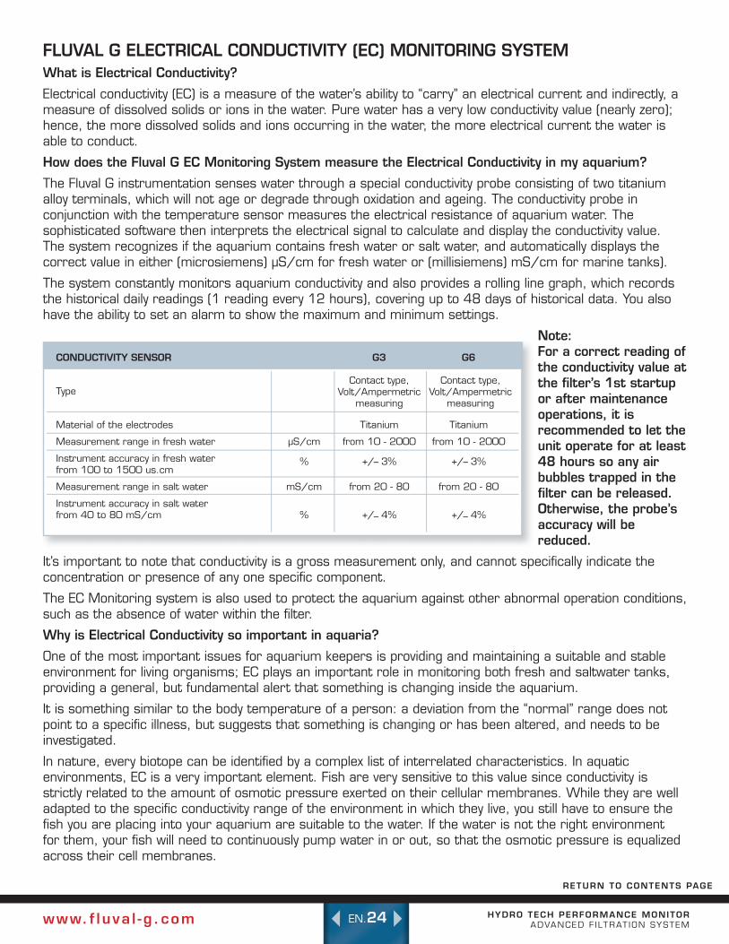
Note: For a correct reading of the conductivity value at the filter’s 1st startup or after maintenance operations, it is recommended to let the unit operate for at least 48 hours so any air bubbles trapped in the filter can be released. Otherwise, the probe’s accuracy will be reduced.
It’s important to note that conductivity is a gross measurement only, and cannot specifically indicate the concentration or presence of any one specific component.
The EC Monitoring system is also used to protect the aquarium against other abnormal operation conditions, such as the absence of water within the filter.
Why is Electrical Conductivity so important in aquaria?
One of the most important issues for aquarium keepers is providing and maintaining a suitable and stable environment for living organisms; EC plays an important role in monitoring both fresh and saltwater tanks, providing a general, but fundamental alert that something is changing inside the aquarium.
It is something similar to the body temperature of a person: a deviation from the “normal” range does not point to a specific illness, but suggests that something is changing or has been altered, and needs to be investigated.
In nature, every biotope can be identified by a complex list of interrelated characteristics. In aquatic environments, EC is a very important element. Fish are very sensitive to this value since conductivity is strictly related to the amount of osmotic pressure exerted on their cellular membranes. While they are well adapted to the specific conductivity range of the environment in which they live, you still have to ensure the fish you are placing into your aquarium are suitable to the water. If the water is not the right environment for them, your fish will need to continuously pump water in or out, so that the osmotic pressure is equalized across their cell membranes.
RETURN TO CONTENTS PAGE
CONDUCTIVITY SENSOR G3 G6
Type
Material of the electrodes Titanium Titanium
Measurement range in fresh water μS/cm from 10 - 2000 from 10 - 2000
Instrument accuracy in fresh water from 100 to 1500 us.cm
% +/_3% +/_3%
Measurement range in salt water mS/cm from 20 - 80 from 20 - 80
Instrument accuracy in salt water from40to80mS/cm % +/_ 4% +/_ 4%
Contact type, Volt/Ampermetric
measuring
Contact type, Volt/Ampermetric
measuring

HYDRO TECH PERFORMANCE MONITOR ADVANCED F ILTRAT ION SYSTEMwww. f luva l - g .com EN.25
More and more hobbyists constantly check the conductivity values of their aquariums as a way to understand at a first glimpse what is changing, and then start a deeper analysis of the situation using water analysis Test Kits.
EC in Freshwater
A couple of examples can clarify the importance of monitoring EC in fresh water tanks:
•Inanewlyestablishedaquarium,theioniccompositionofwatercanvaryconsiderablyduringthefirstfew weeks or months. Some types of gravel can trigger “ion exchange” activity or could either release or trap some ions in water. This could dramatically affect the EC value and the aquarist should evaluate which other parameters are involved (GH and KH in this case), by means of some simple water tests.
•Establishedaquariumsproducewastesthatdirectlyorasaconsequenceofbacteriageneratecharged molecules that result in an increase of the EC. This slow but constant EC increase suggests that some thing is changing in the water; again, by using the proper test kits, it is possible to evaluate which parameter is going out of control. For example, the continuous production of nitrates operated by nitrifying bacteria will result in a correspondent continuous increase of the EC value.
The above mentioned examples clearly indicate how important the EC value is. However, at the same time it cannot be used to directly state the origin of a specific problem, but it is rather a general “alert” signal, which needs interpretation by performing further investigations.
With some experience dealing with this parameter and knowing your aquarium, it will become easier to know what changing conditions the EC readings are showing, and to decide if it is simply time to perform a water change, or whether something else is happening in your tank. Related to this, it is important to track the EC right from the beginning.
In the following example (see graph), the EC value of a 300 liter aquarium has shown an increase of30%in37days.Afterperformingsomechemical analysis, it was possible to see that at least a part of this increase was due to Nitrates, which in the same period have risen from 23 to 40 mg/L as NO3-.
Bysimplymakinga30%waterchange(usingosmoticwater),wewereabletore-establishtheoriginal values to around 250μS/cm.
EC in Saltwater
In marine aquariums, salinity is the most important parameter to measure and maintain. This can be a challenge since there is a narrow range. There are different methods available for measuring salinity, such as specific gravity, refractive index and also conductivity. However, the latter is recognized by scientists as being the most accurate. Your EC Monitor is an easy-to-use, comfortable and reliable way to keep the salinity of your marine aquarium under control.
How can I monitor my aquarium using the Fluval G Filter’s EC Monitor?
Fluval’s G Filer Monitoring System has been designed to help you easily monitor the EC values. You will find that as you become more comfortable with the system, maintaining your EC levels will become quicker and more accurate.
340
330
320
310
300
290
280
270
260
250
2400 10 20 30 40
+30%
µS/cm
DAYS

HYDRO TECH PERFORMANCE MONITOR ADVANCED F ILTRAT ION SYSTEMwww. f luva l - g .com EN.26
Freshwater
When starting a new fresh water aquarium and before introducing fish, it is good practice to measure the water hardness value (GH) and evaluate if this value is suitable for the fish you are about to introduce. In other words, by knowing the GH value of our aquarium water, you can determine which species of fish will thrive in that type of water.
In a newly established aquarium, conductivity will be roughly related to General Hardness (GH= sum of divalent ions, mainly Calcium and Magnesium) and TDS (Total Dissolved Solids) values: μS/cm x 0.5 = ppm TDS x 0.056 = dGH.
Therefore, when buying a freshwater fish, it is very important to know the EC value the fish was living in, and which level will be needed to keep the fish healthy.
For community freshwater tanks, the EC value may generally range from 100 to 300 μS/cm; Discus, Paracheirodon and other soft-water species require values below 100, while Cichlids from African lakes (Malawi e Tanganyika) thrive at values above 500 μS/cm.
Once the most suitable conductivity range for your marine life has been determined, the best use of the conductivity meter in your filter is to monitor the changes in water conditions. Unwanted inorganic and organic pollutants, as well as fertilizers and other chemicals added to the water by the aquarium keeper, directly affect the EC value, generally by increasing it.
In fact, every chemical, additive, piece of food, medication or conditioner you put into your tank affects the conductivity in your aquarium and the above mentioned “link” becomes less. Therefore, measuring conductivity is a way to continuously monitor the conditions of water, since a change in conductivity also indicates a change in water conditions. Any of these changes should be checked using a chemical analysis (test kit). Sometimes the easiest way to correct the EC value is to change the water, thereby reducing the concentration of pollutants.
When starting up a new aquarium, get your water ready before you introduce the new species. Plan for a few days for the water to reach a constant temperature, and the correct EC readings to be established.
If the filter monitor is showing an EC value that is too high, the solution is to dilute the water with an appropriate amount of de-ionized (osmotic) water (a simple formula to calculate how to dilute water is: litres of water needed / actual dGH value x desired dGH value).
E.g.: if your 80 liter tank has a GH value of 20 dGH and you want to reduce this value to 5 dGH the calculationis:80/20x5=20(litersofactualwater)+60
(de-ionized water) = 80 liters of 5 dGH water.
Or, in other words, you need to replace 60 liters of your tank water with de-ionized water.
On the contrary, if the filter monitor shows that the EC value is too low for the species (for example you want to put African cichlids in your aquarium) then you need to “harden” your water. This can be done by using some commercial salt mixes or solutions i.e calcium carbonate.
HYDRO TECH PERFORMANCE MONITOR ADVANCED F ILTRAT ION SYSTEMwww. f luva l - g .com EN.27
Saltwater
Here salinity is the parameter to use in order to control the conductivity measurement.
Other than organisms coming from particular environments and requiring specific salinity levels, salinity should generally average at a conductivity value of 53 mS/cm (= 35 PSU or ppt = 1.0285 specific gravity).
The following comparative table can help if you are more used to salinity or specific gravity than to EC (values at 25 °C; highlighted values are those typical of ocean waters):
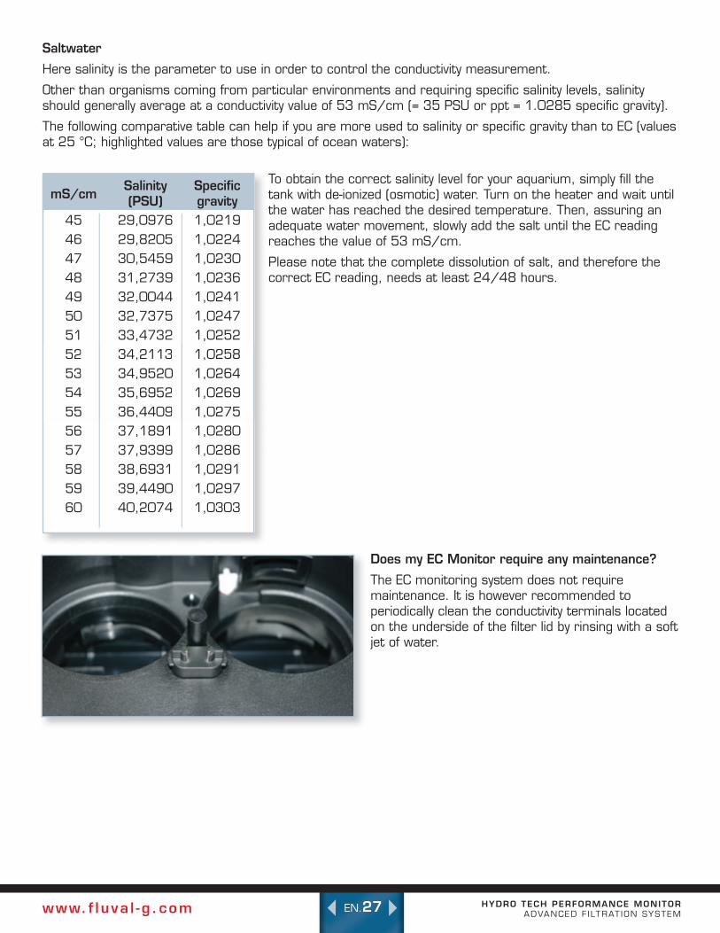
Does my EC Monitor require any maintenance?
The EC monitoring system does not require maintenance. It is however recommended to periodically clean the conductivity terminals located on the underside of the filter lid by rinsing with a soft jet of water.
To obtain the correct salinity level for your aquarium, simply fill the tank with de-ionized (osmotic) water. Turn on the heater and wait until the water has reached the desired temperature. Then, assuring an adequate water movement, slowly add the salt until the EC reading reaches the value of 53 mS/cm.
Please note that the complete dissolution of salt, and therefore the correct EC reading, needs at least 24/48 hours.
mS/cm
45464748495051525354555657585960
Salinity (PSU)
29,097629,820530,545931,273932,004432,737533,473234,211334,952035,695236,440937,189137,939938,693139,449040,2074
Specific gravity1,02191,02241,02301,02361,02411,02471,02521,02581,02641,02691,02751,02801,02861,02911,02971,0303
1,02581,02581,02641,02641,02691,02691,02751,0275
34,211334,211334,952034,952035,695235,695236,440936,4409
5252535354545555

HYDRO TECH PERFORMANCE MONITOR ADVANCED F ILTRAT ION SYSTEMwww. f luva l - g .com EN.28
FILTER MEDIA OPTIONSFLUVAL G FILTER FILTRATION MEDIA Mechanical (Pre-Filter) Cartridges
A healthier aquarium environment is guaranteed through more frequent and easier cartridge cleaning and/or replacement. Due to the special nature of the mechanical pre-filter cartridge, solid waste is removed from the aquarium before it can be solubilized, thus dramatically reducing ammonia and nitrite problems, nitrate and other waste build up. This G filter cartridge system concept is based on preventative maintenance. Remove the waste BEFORE it pollutes the aquarium.
Fluval G3 / G6 Mechanical Pre-Filter Cartridge
The Fluval G3 / G6 Pre-filters are daily use cartridges for the Fluval G3 / G6 Advanced Filter Systems, and will trap suspended
debris for effective mechanical filtration in fresh or marine applications. Designed as a “no by-pass” system, debris remains caught between each pleat until it is removed and rinsed. For extended use, it is recommended that the cartridge is cleaned at least every 2-3 weeks.
Fluval G3/G6 Fine (75µm) Mechanical Pre-Filter Cartridge
The Fluval G3 / G6 Fine Pre-Filter Cartridges are designed for daily use with marine aquariums, where suspended debris is minimal. They can also be used as polishing
cartridges for standard or freshwater aquariums. The fine mesh will trap debris 75μm or larger for unparalleled mechanical filtering results. Designed as a “no by-pass” system, debris remains caught between each pleat until it is removed and rinsed. However, solid wastes can beak down into soluble wastes and regular cartridge rinsing is recommended.
Chemical Cartridges
Fluval G3/G6 Phosphate Cartridges
The Fluval G3 / G6 Phosphate cartridges are for use with the Fluval G3 / G6 Advanced Filter Systems. The G3 cartridge will rapidly remove up to 2200 mg of phosphate ions, and the G6 cartridge will
remove up to 3900 mg of phosphate ions from marine or freshwater aquaria.
Phosphate is one of the main causes of uncontrolled algae growth in aquariums, and its concentration should not exceed 0.5 mg/L in freshwater aquariums and 0.05 mg/L in marine aquariums.
In freshwater aquariums with an excess concentration of 1-2 mg/L phosphate concentration, the use of the Fluval G phosphate cartridges will remove all the excess of phosphate within 1 or 2 days. If left in the filter, it will sustain a low phosphate level for a period of time that is strictly dependent on the type of aquarium it is. (Quantity and type of fish, type of fish food and so on) Phosphate is irreversibly trapped/bound, and will not leach back into aquarium water. The continuous use of the Phosphate cartridge in aquariums with persistent phosphate problems is an effective solution against phosphate build up. If used as a quick solution to reduce elevated phosphate concentration, the cartridge can be removed once levels have normalized, and then stored until required.
It is suggested to regularly monitor the phosphate concentration in the aquarium water; when the concentration value starts to rise, it is time to use or replace the cartridge to ensure the continuous protection against phosphate accumulation.
In the following example, a 600 L freshwater aquarium with high phosphate concentrations (2.2 mg/L) has been treated with the Fluval G6 phosphate cartridge.
RETURN TO CONTENTS PAGE

HYDRO TECH PERFORMANCE MONITOR ADVANCED F ILTRAT ION SYSTEMwww. f luva l - g .com EN.29
The graph shows that phosphate concentration in the water column is reduced and maintained at a safe value for more than two weeks.
Fluval G3/G6 Nitrate Cartridges
The Fluval G3 Nitrate cartridge is for use with the Fluval G3 Advanced Filter System, and will remove up to 13000 mg of nitrate ion in freshwater aquariums. The Fluval G6 Nitrate
cartridge is for use with the Fluval G6 Advanced Filter System, and will remove up to 24000 mg of nitrate ion in freshwater aquariums
Nitrate concentration should not exceed 20 mg/L in freshwater aquariums; however planted aquariums require approximately 5mg/L of nitrate as a source of essential nitrogen for healthy plant growth.
In a 300 L / 600L freshwater aquarium with a 30 mg/L nitrate concentration, the use of G3 / G6 Nitrate cartridge will quickly remove all excess of nitrate in a couple of days. If left in the filter, it will then maintain a low nitrate level for a period of time that is strictly dependent on the type of aquarium it is. (Quantity and type of fish, type of fish food and so on). Nitrate is irreversibly trapped/bound, and will not leach back into the water. The continuous use of the G Nitrate cartridge in aquariums with persis-tent nitrate problems is an effective solution against nitrate accumulation. If used as a quick solution to reduce elevated nitrate concentrations, the cartridge can be removed once levels have normalized, and
then stored until required.
In the following example, a 600L freshwater aquar-ium was treated with the G6 Nitrate Cartridge. The concentration of nitrate was reduced from over 20 mg/L to less than 5 mg/L and remained around this value for over 30 days. Then the concentration started to slowly rise and was back to 20 mg/L in about six months. During this period no water change was performed.
Fluval G3/G6 Tri-Ex Cartridges
Fluval G3 / G6 Tri-Ex cartridge is for use with the Fluval G series of Advanced Filter Systems, and combines the bind-ing power of Fluval G phosphate, nitrate and carbon for an all in one pollution management
solution for fresh water aquariums. With the contin-ued use of Tri-Ex, nitrates, phosphates and organic pollutants remain under control. The G3 cartridge binds over 5000 mg (or more than 15 mg/L in a 300 L aquarium) of nitrate and over 600 mg (or more than 2 mg/L in a 300 L aquarium) of phos-phate. The G6 cartridge binds over 9000 mg (or more than 15 mg/L in a 600 L aquarium) of nitrate and over 1100 mg (or more than 2 mg/L in a 600 L aquarium) of phosphate. The specialized mesh size of the carbon component maximizes the surface to volume ratio for optimized performance.
0 5 10 15
2.5
2
1.5
1
0.5
DAYS
mg/L PO43-
0 20 40 60 80 100 120 140 160 180
25
20
15
10
5
DAYS
Mg/L NO3-

HYDRO TECH PERFORMANCE MONITOR ADVANCED F ILTRAT ION SYSTEMwww. f luva l - g .com EN.30
Spare Chemical Media Cartridge for Fluval G3 or G6
Fluval G re-usable Chemical cartridges are for use with the Fluval G advanced filters. The mesh size of the cartridges are designed to hold most loose or granulated chemical filter media and provide maximum versatility for the hobbyist.
BIOLOGICAL FILTRATION MEDIA
FLUVAL G-NODES
Fluval ceramic G-Nodes fea-ture a complex pore system where beneficial bacterial will thrive. With more capacity and a shape that enables them to be compacted tightly within the G filter baskets, the G-Nodes
enhance biological nitrification, and help reduce am-monia and nitrite.
IMPORTANT: Replenish only 1/3 to 1/2 half at one time to allow proper seeding from older media to new.
OTHER QUALITY FLUVAL FILTRATION OPTIONS
FLUVAL LAB SERIES
OPTI-CARB
Hi-Capacity Ion Exchange Media. Opti-Carb’s mixture of ion-exchange and synthetic organic removal resins, and research grade carbon combine to cre-ate a powerful adsorbent water polishing media. Opti-Carb can
rapidly reduce dissolved organic matter, remove pro-teins before they break down into toxic compounds, and eliminate odors and discolorations. The result is sparkling clear aquarium water. Use as everyday filter media or for removal of specific toxic metals and organic compounds. Does not affect pH, KH and general hardness. Treats up to 189 L (50 US Gal.). For larger tanks use multiple bags.
Formulated for marine/reef aquariums or freshwater environments.
PHOSPHATE REMOVER
Fluval Lab Series Phosphate Remover rapidly adsorbs large quantities of Phosphate, silicate and dissolved organics with-out leaching. Maintaining low levels of phosphate will result in cleaner, healthier aquarium
water while allowing corals to efficiently absorb the calcium they require to grow and reproduce. Phosphate Remover contains ferric oxide, an iron-based phosphate binder, ideal for use in aquarium filters. 150g removes up to 20 mg/L PPM of phosphate in a 50 U.S. Gal. (189 L) aquarium. Will not affect pH or hardness.
For freshwater and marine environments.
NITRATE REMOVER
Fluval Lab Series Nitrate Remover is a high capacity ion exchange resin. Laboratory developed from a pure high grade strong base anion exchange resin, Nitrate
Remover rapidly and selectively removes nitrate and eliminates toxic nitrite in a matter of hours, resulting in a healthy environment for your fish. It’s safe for all fish, plants and invertebrates, will not not affect pH or hardness and is phosphate free.
Resin can be recharged several times. Removes up to 25 mg/L (ppm) of nitrate in a 50 U.S. Gal. (189 L) aquarium.
For freshwater use only.
CARBON
Fluval Carbon is a premium, research grade, low-ash carbon that improves water clarity and color, while also removing odors. Highly porous, it provides large amounts of surface area for
adsorption of impurities. It effectively removes heavy metals, odors, discolorations, organic contaminants, and pollutants to leave your aquarium water crystal clear and sparkling. This product does not release phosphates. Carbon loses its activity without outward sign. Replace every 30 days to ensure that

HYDRO TECH PERFORMANCE MONITOR ADVANCED F ILTRAT ION SYSTEMwww. f luva l - g .com EN.31
active absorption is maintained. Carbon should al-ways be removed when medication is being administered in aquarium water. Also, because carbon will absorb a large percentage of the nutrients in plant fertilizer products, it should be used carefully when keeping live plants.
For freshwater and marine environments.
AMMONIA REMOVER
Fluval Ammonia Remover is a natural ion-exchange medium, designed to remove toxic ammonia as water passes over it. Controlling ammonia levels reduces stress on fish. Use this product to provide a healthy envi-ronment when setting up
a new aquarium, or maintaining one that contains a higher than average fish stock. Ammonia Remover gradually becomes inactive. Replace regularly, at least once a month. For freshwater use only.
ZEO-CARB
Fluval Zeo-Carb is a premium blend of Fluval Carbon and Fluval Am-monia Remover.
Working together, this highly effective media eliminates liquefied impurities, odors, and discoloration, while, at
the same time, removes toxic ammonia, for a clean, healthy aquarium. Combining two products into one gives you more space in your filter system for other types of media. Replace every 30 days, more often if aquarium is heavily populated. Remove when medica-tion is being administered in aquarium water. Use carefully when keeping live plants.
For freshwater use only.
PEAT GRANULES
Fluval Peat Granules are the all-natural way to soften aquar-ium water and achieve the pH levels required for breeding and rearing certain tropical fish. Peat contains humic acid, tanning agents and trace ele-
ments that are essential for various life processes. Highly concentrated for maximum effectiveness, this product is recommended for fish that prefer soft, acidic water. To ensure optimal conditions, it’s best to test with Nutrafin pH and KH test kits on a regular basis to verify that desired levels are being maintained. A KH range of 50-120 mg/L (approximately 3-7 dKH) is usually recommended for fish that thrive in soft, acidic water. (Use Nutrafin pH Stabilizer for superior results in maintaining an optimal KH value.) Replace when pH and KH levels begin to diminish.
For freshwater use only.

HYDRO TECH PERFORMANCE MONITOR ADVANCED F ILTRAT ION SYSTEMwww. f luva l - g .com EN.32
PRIORITY #1 ALERT: SENSING AIR IN THE FILTER
This message appears when there is no water
in the filter. Check that both the chemical and me-chanical filter cartridges have been installed correct-ly, and that the hosing is working.
To bring more water into the unit:
1. Unplug the unit from the electrical outlet.
2. Check the water levels in the aquarium, add more water if necessary.
3. Quickly and vigorously push the priming button all the way down 2-3 times until the water starts flowingintothefilter.
4. When the filter has completely filled with water and all air bubbles have stopped coming out of return nozzles, connect it to the power supply outlet.
5. The LCD display will switch on, and after a short pause, will start up and show the setup sequence of the filter. Once the start sequence hasended,thepumpwillinitiatethewaterflow, provided the filter is completely filled with water.
6. The pump will not operate if the filter is not completely full of water. If the pump is still not filled with water, repeat this process.
If the pump is not filling with water, check the filter cartridges and hoses for any improper installation.
PRIORITY #2 ALERT: BLOCKED IMPELLER
This message appears when the impeller is not operating correctly or the impeller is
missing, and needs to be cleaned.
This part of the filter can’t be scheduled for regular maintenance so it should be checked periodically.
CLEANING THE IMPELLER:
WARNING: This filter-pump is not submersible. Never put the filter lid in water or under water jets.
•Unplugthefilterfromtheelectricaloutlet.Water may spill while cleaning the impeller. You may want to place a towel alongside the filter.
•Openthecartridgelid.ThesilverAQUASTOP valve lever must be completely up and the black AQUASTOP release lever must be completely pushed down in order to open the lid.
•Removeboththepre-filtermechanicaland chemical cartridges by turning the knob counter- clockwise from the “ ” position to the “ ” position.
•Removethefilterheadbyopeningthesilver metal lid fasteners located on each corner of the filer.
•Turnthefilterheadupsidedown.Placeitgently on a towel to absorb any excess water.
Locate the impeller cover. To remove the impeller cover, twist it counter-clockwise. Just before it releases, there will be some resistance, but keep turning the im-peller cover gently until it releases upwards.
Lift the impeller cover up out of its socket. There is a magnet in the middle of the impeller so there will be a slight resistance when you pull it upwards.
If the impeller does not come out with the impeller cover, use the extraction tool to remove the impeller.
in the filter. Check that both the chemical and me-
WARNING MESSAGES/TROUBLESHOOTING/FAQ’s ForadditionalInformationChecktheFAQsectionatwww.fluval-g.com
RETURN TO CONTENTS PAGE

HYDRO TECH PERFORMANCE MONITOR ADVANCED F ILTRAT ION SYSTEMwww. f luva l - g .com EN.33
•Therearethreepartstotheimpeller:
-Ceramicimpellershaft+bottomrubber bushings (glued together)
-Impellerassembly(Magnet+impellerblades)
- Top Rubber bushing which fits into the middle circle of the impeller cover.
•Pullouttheceramicshaft.IMPORTANT: The ceramic shaft is resistant to wear in use, but is still fragile. Handle carefully during cleaning.
•Rinsetheimpellerassemblythoroughlywith clean water.
•Ifnecessary,replacetheimpellerassemblyusing original spare parts.
Put the ceramic shaft back into the magnet. Place the shaft back into the centre part of the cover, gently turning and pressing the rubber bushing until the ceramic shaft is all the way into the top rubber bushing.
•Re-inserttheimpellerassemblybackintothe socket. You’ll feel it pull as the magnet is pulled down into place. Align the impeller cover tabs with the slots on the motor head and twist the cover clockwise until it clicks back into place.
•Putthefilterheadbackontothecanister,making sure to fully press down. Align the lid on the canister. Push down so that all four corners of the lid are all the way down. If any of the corners won’t go all the way down, check that all corner fasteners are fully opened. Do not force.
•Whenthelidisproperlyaligned,closeallfour metal lid fasteners.
•Replacethemechanicalpre-filterand chemical cartridges back into place, making sure to align them properly, and then turn the knobs clockwise to lock cartridges into place. Plug the filter back into the electrical socket.
NOTE: The FLUVAL G6 Upper Bushing consists of a rubber element + a thrust bearing. Normally the thrust bearing remains inside the rubber bushing, but if it comes off or is removed, it must be correctly re-installed before reassembling the unit. The motor cannot operate without it. This applies to the Fluval G6 model only.
PRIORITY #4 ALERT: CONDUCTIVITY OUT OF RANGE
POSSIBLE REASONS FOR AN EC ALERT:
1. There is not enough water in the filter. Check that the filter cartridges and hoses are properly installed, and the aquarium has enough water.
2. The filter has not been operating long enough. The unit should run for 24 hours to release any trapped air bubbles.
3. New gravel has been added triggering an “ion ex change” activity. The solution would be to conduct a simple water test, looking for General Hardness (GH) and KH levels.
4. There is an increase in bacteria due to a build up of waste. For example, the continuous production of nitrifying bacteria caused by continuous nitrate production can trigger an EC warning. A proper test kit can determine if Nitrate level is the problem.
5. Fertilizer, organic and inorganic pollutants or other chemicals have been added to the water, increasing the EC value. This can be corrected by using a chemical analysis test kit.
Read more about Electrical Conductivity in the Electrical Conductivity (EC) Monitoring System Section.

HYDRO TECH PERFORMANCE MONITOR ADVANCED F ILTRAT ION SYSTEMwww. f luva l - g .com EN.34
QUESTIONS & ANSWERS
Q: How can I remove dust, marks or fingerprints from the surface of the filter?
A:Useasoftcloth(micro-fiber70%polyesterand 30%polyamide)ortheblackprotectivesockthat wraps the filter. Do not use paper, abrasive sponges, detergents or alcohol.
Q: I am not able to start the pump using the priming button.
A: 1. Air entering into the intake circuit:
a. Check that the telescopic intake stem and the intake cross rim assembly are correctly assembled and the O-rings are correctly positioned. Disassemble the parts and reassemble them again by applying a twisting movement.
b. Check that the hoses are well inserted into the rim assembly and the ring nuts are properly tightened.
c. Check that the hoses are well positioned into the AQUASTOP and the ring nuts are properly tightened.
d. Check that no dirt is present on the red O-rings of the AQUASTOP.
2. Check that the AQUASTOP valve is fully open (valve lever fully down).
3. Check that there are no slacks or loops in the intake and output hoses.
4. Check that the aquarium water level is not more than 15 cm below your aquarium rim.
5. Check that the hose connected to the intake strainer is attached to the correct adaptor of the AQUASTOP(checkthatthewaterflowfollowsthe direction of the arrows marked on the front of the AQUASTOP).
6.Checkthatthewhiteflapsontheundersideof the priming chamber are not blocked by debris or foreign objects:
a. Remove the mechanical pre-filter cartridge
b. Remove the chemical cartridge
c. Pushing the priming button repeatedly, check thatthetwowhiteflapsinsidethepriming chamber move freely. If this is not the case, remove the cause of the blockage by means of a pencil, gently into the openings.
7. Check that the valves of the primer chamber are still seated properly so they swing freely. In case they are not, proceed as follows:
a. Remove the mechanical pre-filter cartridge
b. Remove the chemical cartridge
c. By pressing the appropriate ribbed areas, remove the red valve support.
d. Remove the valves gasket.
e. Position the valves correctly.
f. Re-assemble all parts.
PRIORITY #5 ALERT: LOW FLOW
The HydroTech system continuously monitors thewaterflowrateand
shouldanythinginhibitwaterflow,youwillseeLowFlow Alert warning.
The Low Flow Alert will appear for several reasons:
•CloggedMechanicalpre-filterCartridge.Checkto see that the mechanical pre- filter has been properly installed and nothing is clogging the area. See Mechanical Filter Maintenance Section for more details on cleaning the filter.
•Wronglyinstalledorwrongfiltrationmedia. The filter comes equipped with a filtration media, but if you choose to use another type of filtering media, check when it needs to be replaced. Please refer to the Filter Media section for further details on how to choose the correct filter media.
•Squeezedorpinchedhosing.Inorderforthe filter to operate properly, hosing should always follow a straight path from the filter to the aquarium rim with some slack but no loops. The filter will not work efficiently if the hose is too long or too short. Check that the hoses have been properly installed.
should anything inhibit water

HYDRO TECH PERFORMANCE MONITOR ADVANCED F ILTRAT ION SYSTEMwww. f luva l - g .com EN.35
NOTES : - In order to work efficiently the priming button must be pushed all of the way down in fast sequence; otherwise the prime may not occur.
- If the installation necessitates slack or dips in the hoses, it may be necessary to use the priming button repeatedly.
- Warning: the priming system works even if the filter canister gasket or the chemical cartridge assembly is missing. Therefore, before priming the unit, check that filter canister gasket and chemical cartridge assembly are in place.
Q: The pre-filter lid doesn’t close.
A: Check that pre-filter handles are properly aligned in the “ ” position
Q: I can’t insert the AQUASTOP valve into the filter top.
A: 1. AQUASTOP orientation is wrong, indicator arrows do not face front.
2. The AQUASTOP release lever has and/or AQUASTOP valve lever have not been lifted to a full upright position before inserting the AQUASTOP.
Q: I can’t remove the AQUASTOP.
A: The AQUASTOP release lever hasn’t been lifted.
Q: I have turned the lock nuts of the AQUASTOP or the Cross Rim assemblies so much that they have fully come off.
A: Replace the lock nuts by turning them clockwise so they screw back down onto the AQUASTOP or Rim Connectors.
Q: I’m not able to pull out the mechanical pre-filter and chemical cartridges.
A: 1. The knob has not been completely turned to the “ “ position. Be sure to turn the knob fully counter-clockwise to remove the cartridges.
2. The power has not been removed from the filter causing suction on the cartridge. Make sure to
remove the power before performing any maintenance procedures.
Q: I’m not able to close the mechanical pre-filter and chemical cartridges.
A: 1. The cartridges’ bayonets have not been inserted in the correct position.
2. The cartridges have been inserted with the wrong orientation.
3. Water level inside the filter has increased due to wrong operations, and this hinders cartridge closing.
4. There is a foreign object inside the filter.
5. The cartridges’ cup got stuck because they have not been correctly installed. Remove the cartridges and repeat the operation.
Q: I’m not able to close the four metal lid fasteners.
A: The filter head is not correctly oriented with respect to the filter body. Not all four metal lid fasteners are fully inside their seats. Assure that all the metal lid fasteners are simultaneously wide open before proceeding with filter head closing operation.
Q: I’m not able to disengage the filter head from the filter canister.
A: Assure that all the four silver metal lid fasteners are simultaneously wide open.
The presence of foreign objects could have generated an anomalous friction. Take off the filter head by simultaneously pulling the appropriate handles (there could be the need of another person helping you). After that, proceed with filter gasket cleaning.
Important: The motor head could get stuck if you try to remove it by pulling one side only. Remove the filter head by pulling with both hands on the proper grip points.
Q: The mechanical cartridge clogs too early.
A: The mechanical cartridge is a high efficiency by-pass-free filter. For this reason everything that is captured by the filter remains trapped in it. The mechanical cartridge has been designed so thatthereisawaterflowreductionof

HYDRO TECH PERFORMANCE MONITOR ADVANCED F ILTRAT ION SYSTEMwww. f luva l - g .com EN.36
15 l/h per day in a mature and average charged aquarium.
An early clogging could be caused by:
- Anomalous production of dirt in the aquarium. Clean the aquarium more frequently and remove the origins of dirt generation.
- The cleaning of the mechanical cartridge is not efficacious. Clean the cartridge in the correct way, by removing the lid at the bottom and using the brush that comes with the unit. (for a better result we suggest rinsing the mechanical cartridge with warm water).
Q: Air bubbles continuously come out from filter output.
A: 1. The filter evacuates the air entering through the intake: remove or relocate the origin of air.
2. During normal operation, the filter may work with a light negative pressure inside, and it could suck air from the connection points. Check the correct assembly and cleanliness of the intake cross rim assembly and stem, AQUASTOP red O-rings, filter canister gasket and cartridges’ O- rings.
3. Filter progressive clogging increases the negative pressure inside the filter, which favours the separation of the gasses dissolved in water. These gases gather inside the filter, and are then expelled through filter outlet. Clean the mechanical pre-filter cartridge.
Q: After switching off and on of the filter, the filter is On and the flow rate is zero or insufficient.
A: An air bubble could be trapped inside the impeller chamber. By acting on the priming button, the operation’s conditions previous to the power being off are restored.
Ifthemechanicalpre-filterisverydirty(lowflow),even the use of the priming button could not be sufficient to solve the problem. In this case clean the mechanical pre-filter cartridge.
Q: After having switched off the unit and cleaned the mechanical pre-filter, the filter is On but flow rate is zero or insufficient.
A: An air bubble could be trapped inside the
impeller chamber. By operating the priming button, the normal operation of the unit can be restored.
Q: After cleaning, max flow rate condition (fully white flow graph) is not restored.
A:Thesystemmeasuresthewaterflowbyreading the electrical parameters of the pump, and it has been calibrated by referring to a standard application, i.e. intake and output hoses of the samelength1,5m,telescopicstem+strainer +regularcrossrimdeviceatintake,twinnozzles +regularcrossrimdeviceatoutputand AQUASTOP valve fully open.
Different configurations may introduce different hydraulic circuit losses and consequently delay or acceleratetheindicationofflowreduction.
Atooearlywaterflowreductionmaybealsocausedby:
1. Accidentally squeezed or collapsed hosing
2. AQUASTOP valve lever not fully lowered
3. Clogged hosing or cross rim assembly
4. Solids, debris or bacterial mud, block water passage inside the filter or at pump outlet.
5. The valves of the priming system are dirty or blocked
6. The chemical cartridge is still inside the protective poly-bag
7. Filtration media block pump inlet
Q: When removing the filter head from the unit, water comes out from the metal locking levers.
A: In order to avoid water spilling when cleaning, during normal operation, the filter unit is not completely full of water, but it maintains an air chamber underneath the filter head to keep water inside at such a level so that it does not overflow.
During normal operations of cartridges opening or AQUASTOP disengagement, water level inside tends to rise.
Wrong operations may cause water to spill and to gather inside the unit head.
The cartridge cups also serve the purpose by remov-ing some water from the unit during maintenance operation, and thus restoring the adequate water level.

HYDRO TECH PERFORMANCE MONITOR ADVANCED F ILTRAT ION SYSTEMwww. f luva l - g .com EN.37
Wrong operations not to perform include:
- Releasing, re-engaging the AQUASTOP and opening the AQUASTOP valves, the whole sequence more than 2 times without removing one of the cartridges or emptying the unit.
- Closing the AQUASTOP valve, opening one of the cartridges, closing the cartridge and opening the AQUASTOP valve, the whole sequence more than 2 times consequently.
- Removing one of the cartridges and pouring the content of the cartridge cup back into the unit.
- Re-inserting the cartridge without having previously emptied the cartridge cup.
- Re-inserting the cartridge too rapidly. (splash effect)
- Removing one of the cartridges and opening the AQUASTOP valve lever.
Q: There is water under filter canister feet.
A: 1. During filter cartridge maintenance, water has seeped into the gap between the motor base and the top shell and is siphoning between the filter canister layers.
2. A gasket (probably that of the filter canister) or the chemical cartridge is missing.
Q: The conductivity graph shows sudden drops.
A: The conductivity reading is only precise and stabilized after 24-48 hours of filter operation.
Variations may be due to:
- Toping off aquarium with clean water
- Cleaning or maintenance operations, after which the reading is not accurate for 24hrs.
- Sudden infiltration of air into the system.
- Conductivity sensor pins have been cleaned the wrong way (do not clean conductivity metal pins with paper, detergents, cloth etc. Simply rinse them with clean water).
- The mechanical cartridge is clogged.

HYDRO TECH PERFORMANCE MONITOR ADVANCED F ILTRAT ION SYSTEMwww. f luva l - g .com EN.38
11
12
08 09
22
16
17
20
21
19
24
10
01
02
06
05
07
03
04
18
25
23
14
15
26
13
01. Priming button02. Priming chamber03. Mechanical cartridge04. Mechanical cartridge cup05. Chemical cartridge cap 06. Chemical cartridge07. Chemical cartridge cup08. AQUASTOP release lever09. AQUASTOP valve lever10. AQUASTOP11. Filter head 12. Biological basket cover 13. Biological baskets [G3 x 2/G6 x 3]
14. Filter canister gasket15. Filter canister16. Cross rim assembly17. Rim attachment18.Outputnozzle+extension19. Hosing20. Spray bar suction cups 21. Spray bars22. Telescopic intake stem23. Intake strainer24. Cartridge lid25. Impeller assembly26.Impellercover+“O”ring
EXPLODED PARTS VIEW
RETURN TO CONTENTS PAGE

HYDRO TECH PERFORMANCE MONITOR ADVANCED F ILTRAT ION SYSTEMwww. f luva l - g .com EN.39
REPLACEMENT PARTS Order replacement part from your Fluval dealer or by contacting Customer Service
A20250Fluval G3 & G6 Hosing 3m (9.8’)
A20255Fluval G3 & G6 Gasket Kit
A20251Fluval G3 & G6 Rim Connector Assembly with Suction Cups
A20260Fluval G3 Magnetic Impeller Assembly with Impeller Cover
A20252Fluval G3 & G6 Water Return Kit
A20262Fluval G6 Magnetic Impeller Assembly with Impeller Cover
A20256Fluval G3 & G6 Primer Assembly
A20254Fluval G3 & G6 AQUASTOP Valve
A20257Fluval G3 & G6 Output Extension
A20253G3 & G6 Water Intake Kit
RETURN TO CONTENTS PAGE

HYDRO TECH PERFORMANCE MONITOR ADVANCED F ILTRAT ION SYSTEMwww. f luva l - g .com EN.40
FILTER SPECIFICATIONS
FLUVAL G3 Filter Dimensions (L x W x H): 249x249x247mm
Aquarium Capacity: 150-300 l -- 40-80gal.
Pump Output: 230-240V/50Hz: 1285 l/h – 340 g/h 120V/60Hz: 1380 l/h - 365 g/h
Mechanical Cartridge: 520 cm2
Biological Volume: 2.36 l - 0.6 gal.
Filtration Volume: 5.0 l - 1.32 gal.
Filter Circulation*: 700 l/h - 185 g/h
Head Height: 50Hz: 180 cm - 5.10 ft 60Hz: 190 cm - 6.2 ft
Wattages: 120V/60Hz: 18W 230-240V/50Hz: 17W
FLUVAL G6 Filter Dimensions (L x W x H): 249x249x326mm
Aquarium Capacity: 300-600 l -- 80-160gal.
Pump Output: 230-240V/50Hz: 2460 l/h – 650 g/h 120V/60Hz: 2510 l/h -665 g/h
Mechanical Cartridge: 980 cm2
Biological Volume: 4.0 l -1.05 gal.
Filtration Volume: 8.7 l -2.3 gal.
Filter Circulation*: 1.000 l/h -265 g/h
Head Height: 50Hz: 210 cm - 6.10 ft 60Hz: 230 cm - 7.6 ft
Wattages: 120V/60Hz: 27W 230-240V/50Hz: 28W
*Initialflowrateincludingfiltrationmedia,standardlengthhoseandoutputnozzles
RETURN TO CONTENTS PAGE

EN.41
LCD SCREEN FLOW MAP
HYDRO TECH PERFORMANCE MONITOR ADVANCED F ILTRAT ION SYSTEMwww. f luva l - g .com
RETURN TO CONTENTS PAGE

HYDRO TECH PERFORMANCE MONITOR ADVANCED F ILTRAT ION SYSTEMwww. f luva l - g .com EN.42
Fluval G Advanced Filtration System offers a 2-year warranty from the date of purchase against defects in material or workmanship under normal aquarium usage and service. We offer a 2-Year warranty on all non- replaceable parts, which means that the filter will be repaired or replaced at the manufacturer’s discretion, free of charge, when the complete pump is returned with proof of purchase and postage paid. Please include $4.00 to cover shipping and handling.
To register your warranty or for further information, go to www.fluval-g.com. To register your warrantee you will need the model (G3 or G6) and serial number marked on the back of the Fluval G Filter. Make sure to have this information handy as you will be required to provide this information when registering your warranty.
If you have a problem or question concerning the operation of the Fluval G filter, please let us try to help you before you return the product to your dealer. Most problems can be handled promptly with a phone call. Or, if you prefer, you can contact us on our web site at www.hagen.com. Or visit www.fluval-g.com for more information. When you contact us please have all relevant information, such as model number and/or part numbers available, as well as the nature of the problem.
TWO YEAR WARRANTY
CANADA Rolf C. Hagen Inc. 20500 Trans Canada Hwy, Baie d’Urfé, QC H9X 0A2 Tel: (800) 554-2436
USA Rolf C. Hagen (U.S.A.) Corp. 305 Forbes Blvd. Mansfield, MA 02048 Tel: (800) 724-2436
www.fluval-g.com
UK Customer Service Department Rolf C. Hagen (UK) Ltd.California Drive Whitwood Industrial Estate, Castleford WF10 5QH, West Yorkshire Tel: 01977556622
FRANCE Rolf C. Hagen (France) SA. Zone Parisud 4 Boulevard Jean Monnet F-77388 Comb la Ville. Tel:+33164881418
GERMANY HAGEN Deutschland GmbH & Co. KGLehmweg 99-105 25488 Holm Tel: 0180 1 42 43 63
MALAYSIA Rolf C. Hagen (SEA) Sdn Bhd. Lot 14A, Jalan 3A, Kawasan Perusahaan Cheras Jaya Balakong, 43200 Chears, Selangor Darul Ehsan Tel:+60390742388
SPAIN Rolf C. Hagen España S.A. Avda. de Beniparrell, 11 y 13 P.I. L’Altero 46460 Silla Valencia, Spain Tel:+34961200945
RETURN TO CONTENTS PAGE