USER GUIDE Ambulatory infusion...
79
USER GUIDE Ambulatory infusion pump
Transcript of USER GUIDE Ambulatory infusion...
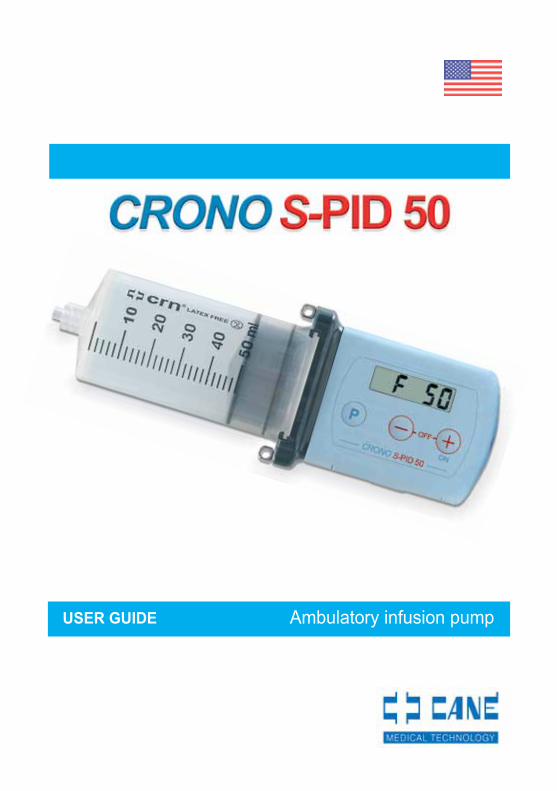
USER GUIDE Ambulatory infusion pump

Manual code: MAN 01/USA/03 S-PID 50Date of publication: 07/09
Firmware version: S5P.02.00 Firmware date: 18/10/07
US Federal law restricts this device for sale by or on order of a physician.
CANè S.p.A. Medical TechnologyVia Cuorgnè 42/a 10098 Rivoli (TO) Italy
Tel.+39 011 9574872 - Fax +39 011 9598880www.canespa.it - [email protected]
3MAN 01/USA/03 S-PID 50 07/09
SECTION 1Symbols and conventions................................................. page 7CAUTION ......................................................................... page 7Introduction ....................................................................... page 8
SECTION 2Intended use ..................................................................... page 10WARNING ........................................................................ page 10
SECTION 3Infusion system................................................................. page 12Description of the pump.................................................... page 12Technical characteristics................................................... page 13
SECTION 4Factory settings ................................................................ page 15Information........................................................................ page 15
SECTION 5Equipment ........................................................................ page 16Optional accessories available on request ....................... page 17How to use the accessories provided ............................... page 20
SECTION 6Identifying the device components ................................... page 21Liquid crystal display ........................................................ page 22Examples of indications appearing on the display ........... page 23Keypad ............................................................................. page 25
SECTION 7Reservoir .......................................................................... page 26Luer Lock cap ................................................................... page 27Profill-crn needle............................................................... page 27Filtrajet .............................................................................. page 28Y-set ................................................................................. page 28
INDEX

4MAN 01/USA/03 S-PID 50 07/09
INDEX
Infusion set ....................................................................... page 29Identifying the infusion set components ........................... page 29Infusion preparation .......................................................... page 29Preparing the reservoir ..................................................... page 30Attaching the reservoir to the device ................................ page 32
SECTION 8Keypad lock ...................................................................... page 35Warning ............................................................................ page 35
SECTION 9Initialization of the pump ................................................... page 36
SECTION 10Setting and inserting the battery ....................................... page 37Setting in the OFF condition ............................................ page 38Flow chart of settings in the OFF conditions .................... page 39Infusion end acoustic signal ............................................ page 40Setting the number of infusion sites ................................. page 40Setting the partial volume ................................................. page 42Settings in the ON condition ............................................ page 44Setting the infusion duration ............................................. page 44Flow rate setting ............................................................... page 45
SECTION 11Switching on the pump in time mode................................ page 46Switching on the pump in flow rate mode ......................... page 47Pump in operation ............................................................ page 48Infusion set refilling (Prime) .............................................. page 48Withdrawal ........................................................................ page 50Pushing unit movement .................................................... page 50Occlusion .......................................................................... page 52Post-Occlusion Bolus ....................................................... page 52

5MAN 01/USA/03 S-PID 50 07/09
Infusion end ...................................................................... page 53Switching off ..................................................................... page 54Infusion number display ................................................... page 54Saving set data ................................................................. page 54
SECTION 12Battery low warning .......................................................... page 55Replacing the battery........................................................ page 56BATTERY CARE .............................................................. page 58
SECTION 13GENERAL WARNINGS .................................................... page 59
SECTION 14Manual updates ................................................................ page 60Maintenance .................................................................... page 60Cleaning ........................................................................... page 60GENERAL WARNINGS .................................................... page 60Storage ............................................................................. page 60Disposal ............................................................................ page 61Expected life of the pump ................................................. page 61
SECTION 15Customer Support ............................................................ page 62Warranty regulations ........................................................ page 62
SECTION 16Error signals ..................................................................... page 64Customer Support Service ............................................... page 65
SECTION 17Instructions in short .......................................................... page 66
6MAN 01/USA/03 S-PID 50 07/09
SECTION 18Symbols on the pump ....................................................... page 70Symbols on the syringe blister package ........................... page 71
SECTION 19Declaration of compliance ................................................ page 72
ATTACHMENTSAttachment 1 .................................................................... page 73Attachment 2 .................................................................... page 75Attachment 3 .................................................................... page 76
7MAN 01/USA/03 S-PID 50 07/09
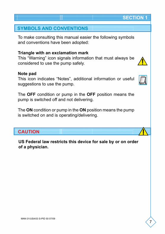
To make consulting this manual easier the following symbols and conventions have been adopted:
Triangle with an exclamation markThis “Warning” icon signals information that must always be considered to use the pump safely.
Note padThis icon indicates “Notes”, additional information or useful suggestions to use the pump.
The OFF condition or pump in the OFF position means the pump is switched off and not delivering.
The ON condition or pump in the ON position means the pump is switched on and is operating/delivering.
SYMBOLS AND CONVENTIONS
SECTION 1
US Federal law restricts this device for sale by or on order of a physician.
CAUTION
8MAN 01/USA/03 S-PID 50 07/09
INTRODUCTION
Thank you for choosing the CRONO S-PID 50 ambulatory infusion pump.
This manual was written to ensure the optimal use of the pump.
The instructions contained in this manual only concern the CRONO S-PID 50 ambulatory infusion pump and are addressed to the medical and paramedical personnel who must initially apply the pump and subsequently to patients.
The pump is fitted with a keypad lock system (see page 35) that prevents any change to the programmed parameters. The informa-tion concerning the keypad lock/unlock procedure is provided at the end of this manual on a plasticized card.
The purpose of the keypad lock is to prevent accidental or unauthorized changes to the selected parameters; in cases in which it is appropriate for the patient not to know this procedure, the doctor and/or the assistant is advised not to provide the patient with this information.
The instructions contained in this manual are fundamental for safe, correct use of the pump.
Users are advised to read the entire manual before using the device and keep it for future reference.
The pump does not require any installation, testing and/or commissioning.
CANè S.p.A. reserves the right to modify the hardware and software specifications described in this manual at any time and without warning.
SECTION 1
9MAN 01/USA/03 S-PID 50 07/09
NOTES
CANè S.p.A. reserves the right to modify and/or update this manual at any time and without warning.
With the purpose of making this manual complete and precise, please notify us of any errors or omissions at the following email address: [email protected].
SECTION 1
10MAN 01/USA/03 S-PID 50 07/09
SECTION 2
The CRONO S-PID 50 ambulatory infusion pump has been desig-ned exclusively for subcutaneous immunoglobulin infusions.
Administration of medication with other methods and therapies shall exempt CANè S.p.A. from any responsibility.
INTENDED USE
The manufacturer undertakes responsibility in association with the safety and operation of the device, provided that it is used in com-pliance with these instructions and that any repairs and/or changes have been performed exclusively by the same manufacturer.
NOTE
WARNINGImproper programming and/or the incomplete understanding of operating functions and alarms may cause death or serious injuries to the patient.
Before using the pump assess its suitability for the type of use and the patient by carefully considering the following aspects:- the technical specifications of the pump;- the infusion sets that will be used;- any use of multiple infusion sets and clamps along the infusion line;- the type of therapy in the treatment of primitive immunodeficiency,
which the patient is undergoing;- the psychophysical and cognitive conditions of the patient.The list above is not exhaustive and is provided for purposes of example only, with regard to the clinical procedural aspects, the responsibility of which is borne by the medical or paramedical personnel.
The device must be used:• under strict medical control,• adopting suitable procedures and adequate measures towards those patients who may suffer serious consequences (injury or death) following involuntary operations and/or breakdowns with the consequent interruption in the administration of the medication.
11MAN 01/USA/03 S-PID 50 07/09
Do not prime the infusion line when connected to the patient since this may cause a medication overdose.
Before starting an infusion, inspect the route of the fluid to make sure that there are no folds, clamps or other occlusions upstream; remove any air bubbles.
After inserting the needle check, by means of suction, that it has not been introduced into a vein or in a capillary (for further details on the procedure to use, please refer to your family doctor).
The accuracy and the amount of time necessary to signal an occlu-sion may vary from the values indicated in this manual, depending on the type of catheter, the infusion set and all the elements in the infusion line.
In case of suspected damage to the pump for any reason (for example due to infiltration of liquid or bangs), contact the Customer Support Service to ascertain the correct operation of the pump. Do not use the pump if damaged.
For doubts concerning the operation of the pump and/or in case of anomalies, interrupt the use of the device and contact the technical assistance service.
Any trace of liquid on the outer part of the pump must be immediately removed with paper towels.
It is important to arrange a procedure and/or system as an alterna-tive to that of the infusion through a pump in case this breaks. A valid solution may be to arrange both a second pump and an alternative system to it.
It is worthwhile that the people who assist and/or live with the user of the pump know how the pump works and the information contained in the instruction manual.
It is important to interrupt the use of the device after its forecast service life following the instructions for its correct disposal.
SECTION 2
12MAN 01/USA/03 S-PID 50 07/09
SECTION 3
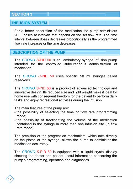
The CRONO S-PID 50 is an ambulatory syringe infusion pump intended for the controlled subcutaneous administration of medication.
The CRONO S-PID 50 uses specific 50 ml syringes called reservoirs.
The CRONO S-PID 50 is a product of advanced technology and innovative design. Its reduced size and light weight make it ideal for home use with consequent freedom for the patient to perform daily tasks and enjoy recreational activities during the infusion.
The main features of the pump are:- the possibility of selecting the time or flow rate programming
mode;- the possibility of fractionating the volume of the medication
contained in the syringe in more than one infusion site (in flow rate mode).
The precision of the progression mechanism, which acts directly on the piston of the syringe, allows the pump to administer the medication accurately.
The CRONO S-PID 50 is equipped with a liquid crystal display showing the doctor and patient useful information concerning the pump’s programming, operation and diagnostics.
DESCRIPTION OF THE PUMP
INFUSION SYSTEM
For a better absorption of the medication the pump administers 20 µl doses at intervals that depend on the set flow rate. The time interval between doses decreases proportionally as the programmed flow rate increases or the time decreases.
13MAN 01/USA/03 S-PID 50 07/09
SECTION 3
TECHNICAL CHARACTERISTICS
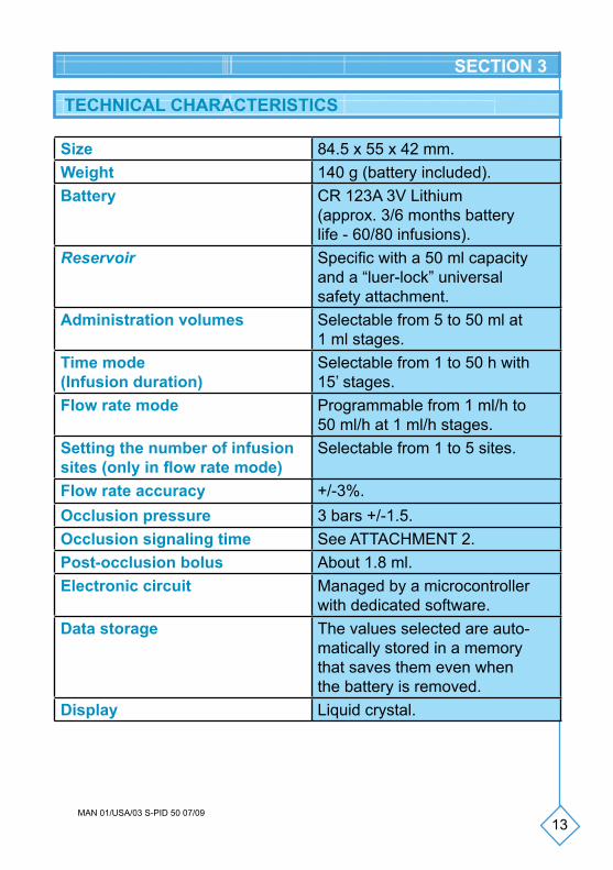
Size 84.5 x 55 x 42 mm. Weight 140 g (battery included).Battery CR 123A 3V Lithium
(approx. 3/6 months battery life - 60/80 infusions).
Reservoir Specific with a 50 ml capacity and a “luer-lock” universal safety attachment.
Administration volumes Selectable from 5 to 50 ml at 1 ml stages.
Time mode(Infusion duration)
Selectable from 1 to 50 h with 15’ stages.
Flow rate mode Programmable from 1 ml/h to 50 ml/h at 1 ml/h stages.
Setting the number of infusion sites (only in flow rate mode)
Selectable from 1 to 5 sites.
Flow rate accuracy +/-3%.Occlusion pressure 3 bars +/-1.5.Occlusion signaling time See ATTACHMENT 2.Post-occlusion bolus About 1.8 ml. Electronic circuit Managed by a microcontroller
with dedicated software.Data storage The values selected are auto-
matically stored in a memory that saves them even when the battery is removed.
Display Liquid crystal.
14MAN 01/USA/03 S-PID 50 07/09
SECTION 3
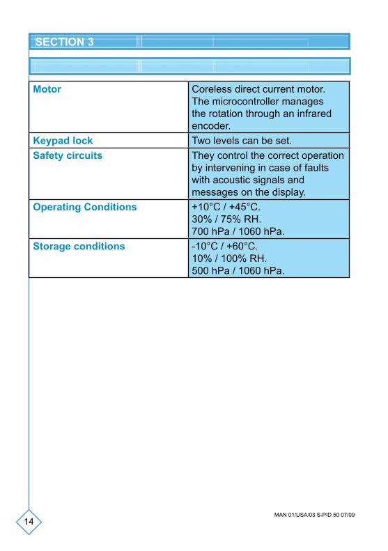
Motor Coreless direct current motor. The microcontroller manages the rotation through an infrared encoder.
Keypad lock Two levels can be set.Safety circuits They control the correct operation
by intervening in case of faults with acoustic signals and messages on the display.
Operating Conditions +10°C / +45°C. 30% / 75% RH. 700 hPa / 1060 hPa.
Storage conditions -10°C / +60°C. 10% / 100% RH. 500 hPa / 1060 hPa.
15MAN 01/USA/03 S-PID 50 07/09
SECTION 4
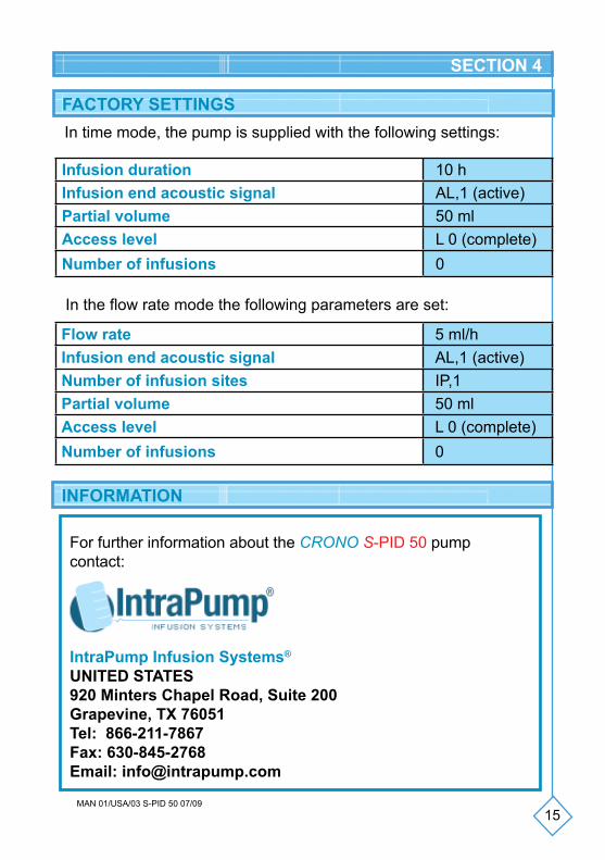
Infusion duration 10 hInfusion end acoustic signal AL,1 (active)Partial volume 50 mlAccess level L 0 (complete)Number of infusions 0
FACTORY SETTINGS
INFORMATION
In time mode, the pump is supplied with the following settings:
For further information about the CRONO S-PID 50 pumpcontact:
IntraPump Infusion Systems®
UNITED STATES920 Minters Chapel Road, Suite 200Grapevine, TX 76051Tel: 866-211-7867Fax: 630-845-2768Email: [email protected]
Flow rate 5 ml/hInfusion end acoustic signal AL,1 (active)Number of infusion sites IP,1Partial volume 50 mlAccess level L 0 (complete)Number of infusions 0
In the flow rate mode the following parameters are set:
16MAN 01/USA/03 S-PID 50 07/09
SECTION 5
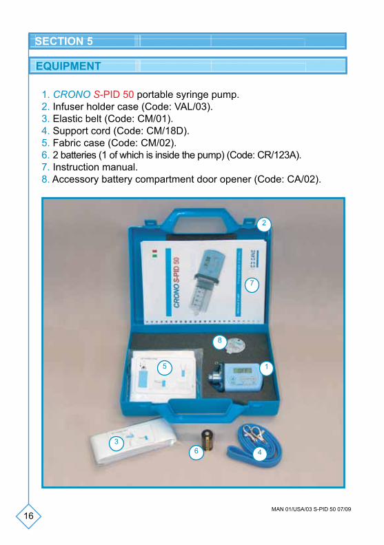
EQUIPMENT
1. CRONO S-PID 50 portable syringe pump.2. Infuser holder case (Code: VAL/03).3. Elastic belt (Code: CM/01).4. Support cord (Code: CM/18D).5. Fabric case (Code: CM/02).6. 2 batteries (1 of which is inside the pump) (Code: CR/123A).7. Instruction manual.8. Accessory battery compartment door opener (Code: CA/02).
1
2
34
5
6
7
8
17MAN 01/USA/03 S-PID 50 07/09
SECTION 5
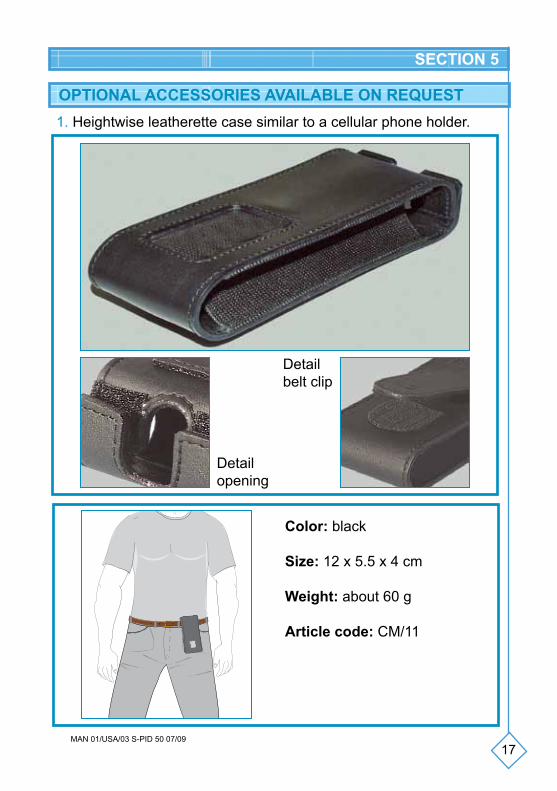
OPTIONAL ACCESSORIES AVAILABLE ON REQUEST1. Heightwise leatherette case similar to a cellular phone holder.
Color: black
Size: 12 x 5.5 x 4 cm
Weight: about 60 g
Article code: CM/11
Detail belt clip
Detailopening
18MAN 01/USA/03 S-PID 50 07/09
SECTION 5
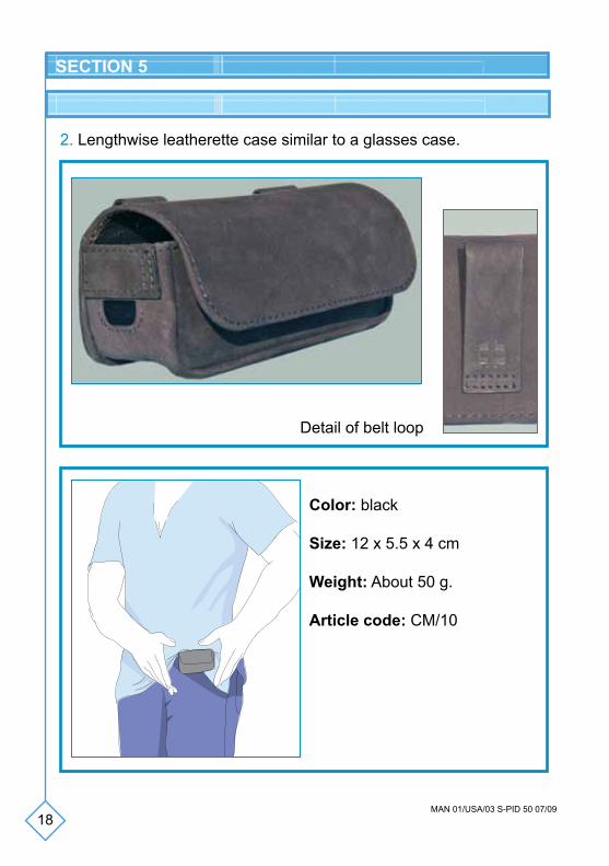
2. Lengthwise leatherette case similar to a glasses case.
Color: black
Size: 12 x 5.5 x 4 cm
Weight: About 50 g.
Article code: CM/10
Detail of belt loop
19MAN 01/USA/03 S-PID 50 07/09
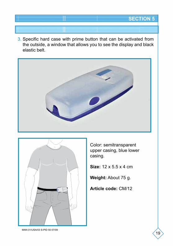
3. Specific hard case with prime button that can be activated from the outside, a window that allows you to see the display and black elastic belt.
SECTION 5
Color: semitransparent upper casing, blue lower casing.
Size: 12 x 5.5 x 4 cm
Weight: About 75 g.
Article code: CM/12
20MAN 01/USA/03 S-PID 50 07/09
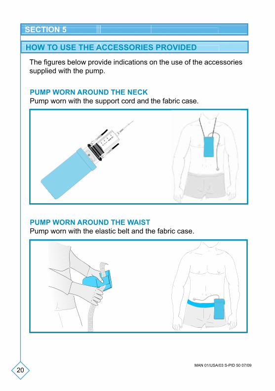
PUMP WORN AROUND THE NECKPump worn with the support cord and the fabric case.
PUMP WORN AROUND THE WAISTPump worn with the elastic belt and the fabric case.
SECTION 5
The figures below provide indications on the use of the accessories supplied with the pump.
10
20
30
ml
40
50
HOW TO USE THE ACCESSORIES PROVIDED
21MAN 01/USA/03 S-PID 50 07/09
PUMP WORN AROUND THE WAISTPump worn with the elastic belt and the fabric case.
SECTION 6
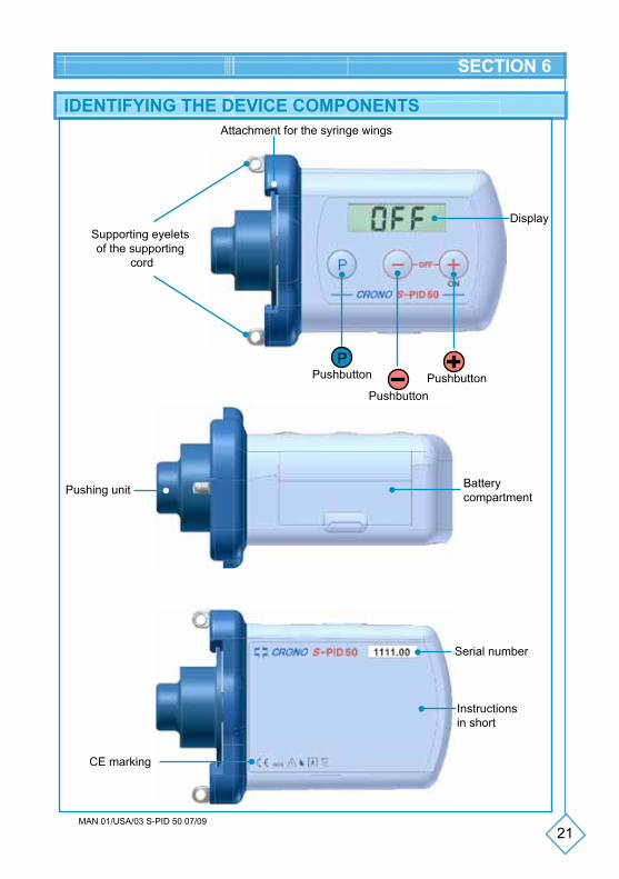
IDENTIFYING THE DEVICE COMPONENTSAttachment for the syringe wings
Supporting eyeletsof the supporting
cord
Display
Pushbutton
PushbuttonPushbutton
P
Battery compartment
Serial number
Instructions in short
CE marking
Pushing unit
22MAN 01/USA/03 S-PID 50 07/09
SECTION 6
LIQUID CRYSTAL DISPLAY
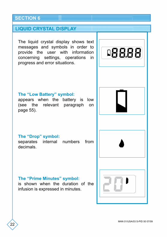
The liquid crystal display shows text messages and symbols in order to provide the user with information concerning settings, operations in progress and error situations.
The “Low Battery” symbol:appears when the battery is low (see the relevant paragraph on page 55).
The “Drop” symbol:separates internal numbers from decimals.
The “Prime Minutes” symbol: is shown when the duration of the infusion is expressed in minutes.
10
20
10
20
23MAN 01/USA/03 S-PID 50 07/09
SECTION 6
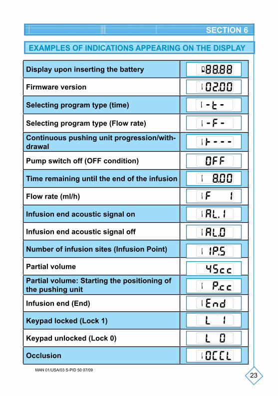
EXAMPLES OF INDICATIONS APPEARING ON THE DISPLAY
Display upon inserting the battery
Firmware version
Selecting program type (time)
Selecting program type (Flow rate)
Continuous pushing unit progression/with-drawal
Pump switch off (OFF condition)
Time remaining until the end of the infusion
Flow rate (ml/h)
Infusion end acoustic signal on
Infusion end acoustic signal off
Number of infusion sites (Infusion Point)
Partial volume
Partial volume: Starting the positioning of the pushing unit
Infusion end (End)
Keypad locked (Lock 1)
Keypad unlocked (Lock 0)
Occlusion
10
20
10
20
10
20
10
20
10
20
10
20
10
20
10
20
10
20
10
20
10
20
10
20
10
10
20
24MAN 01/USA/03 S-PID 50 07/09
SECTION 6
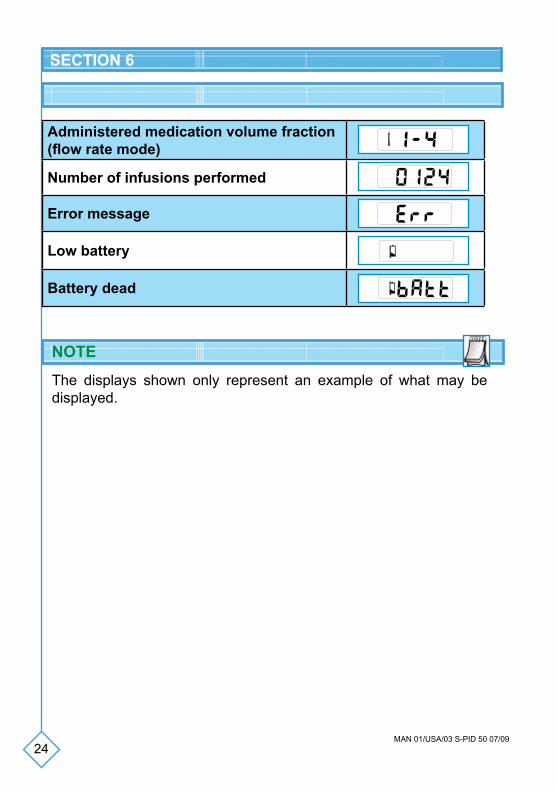
Administered medication volume fraction (flow rate mode)
Number of infusions performed
Error message
Low battery
Battery dead
The displays shown only represent an example of what may be displayed.
10
20
��
��
10
20
NOTE
25MAN 01/USA/03 S-PID 50 07/09
SECTION 6
KEYPAD
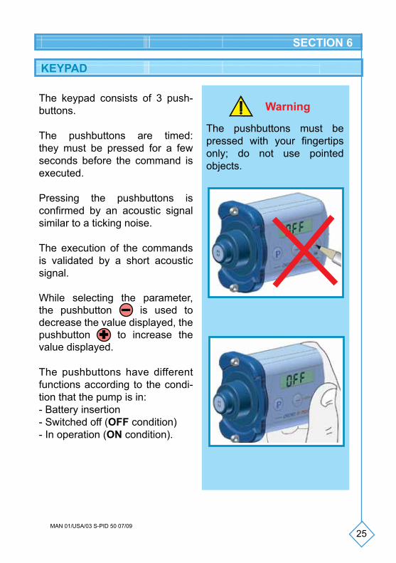
The keypad consists of 3 push-buttons.
The pushbuttons are timed: they must be pressed for a few seconds before the command is executed.
Pressing the pushbuttons is confirmed by an acoustic signal similar to a ticking noise.
The execution of the commands is validated by a short acoustic signal.
While selecting the parameter, the pushbutton is used to decrease the value displayed, the pushbutton to increase the value displayed.
The pushbuttons have different functions according to the condi-tion that the pump is in:- Battery insertion- Switched off (OFF condition)- In operation (ON condition).
Warning
The pushbuttons must be pressed with your fingertips only; do not use pointed objects.
26MAN 01/USA/03 S-PID 50 07/09
SECTION 7
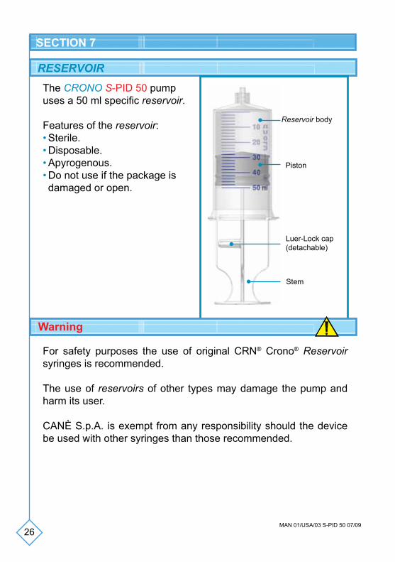
The CRONO S-PID 50 pump uses a 50 ml specific reservoir.
Features of the reservoir:• Sterile.• Disposable.• Apyrogenous.• Do not use if the package is damaged or open.
Reservoir body
Piston
Stem
For safety purposes the use of original CRN® Crono® Reservoir syringes is recommended.
The use of reservoirs of other types may damage the pump and harm its user.
CANè S.p.A. is exempt from any responsibility should the device be used with other syringes than those recommended.
Luer-Lock cap(detachable)
Warning
RESERVOIR

27MAN 01/USA/03 S-PID 50 07/09
SECTION 7
LUER LOCK CAPThe Luer lock cap is connected to the stem of the reservoir from which it is detached by applying a little pressure. Functions of the Luer Lock cap:
• After filling the reservoir it assists in unscrewing the stem from the piston, avoiding spilling the medication;
• It assists in the correct connection between the pushing unit of the pump and the rubber piston of the syringe;
• It protects the medication inside the reservoir in case it is not immediately used.
PROFILL-CRN NEEDLEThe PROFILL-CRN needle may be used for:
• piercing the rubber membrane of the containers of the medication;
• draining the medication to fill the 50 ml reservoir.
Features of the needle: 14G - 38 mm, sterile, disposable, apyro-genous, do not use if the package is damaged or open.
WarningDo not use the needle for injections
and/or samples.
Luer Lock capmale
Needle
Needle cover
Luer Lock cap
28MAN 01/USA/03 S-PID 50 07/09
SECTION 7
FILTRAJET
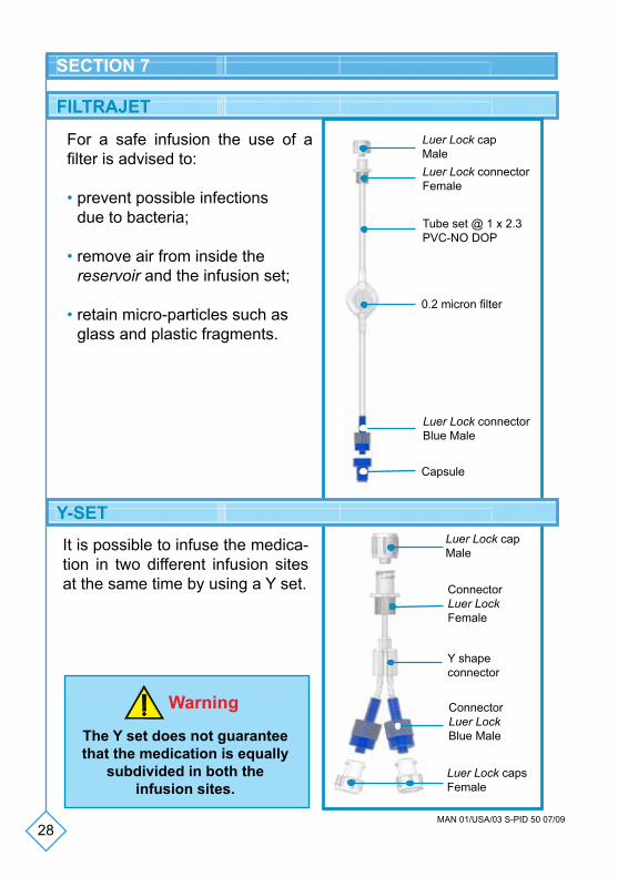
For a safe infusion the use of a filter is advised to:
• prevent possible infections due to bacteria;
• remove air from inside the reservoir and the infusion set;
• retain micro-particles such as glass and plastic fragments.
Luer Lock capMaleLuer Lock connectorFemale
Tube set @ 1 x 2.3PVC-NO DOP
0.2 micron filter
Luer Lock connectorBlue Male
Capsule
Y-SETLuer Lock capMale
Luer Lock capsFemale
ConnectorLuer LockFemale
ConnectorLuer LockBlue Male
Y shape connector
It is possible to infuse the medica-tion in two different infusion sites at the same time by using a Y set.
Warning
The Y set does not guarantee that the medication is equally
subdivided in both theinfusion sites.
29MAN 01/USA/03 S-PID 50 07/09
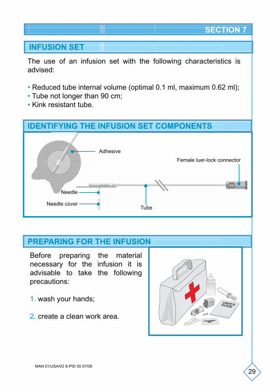
INFUSION SET
The use of an infusion set with the following characteristics is advised:
• Reduced tube internal volume (optimal 0.1 ml, maximum 0.62 ml);• Tube not longer than 90 cm;• Kink resistant tube.
PREPARING FOR THE INFUSIONBefore preparing the material necessary for the infusion it is advisable to take the following precautions:
1. wash your hands;
2. create a clean work area.
OFF
MICROJ
ET CRO
NO
0.2 ml
d
h
min
IDENTIFYING THE INFUSION SET COMPONENTS
Adhesive
Needle
Needle coverTube
Female luer-lock connector
SECTION 7
30MAN 01/USA/03 S-PID 50 07/09
SECTION 7
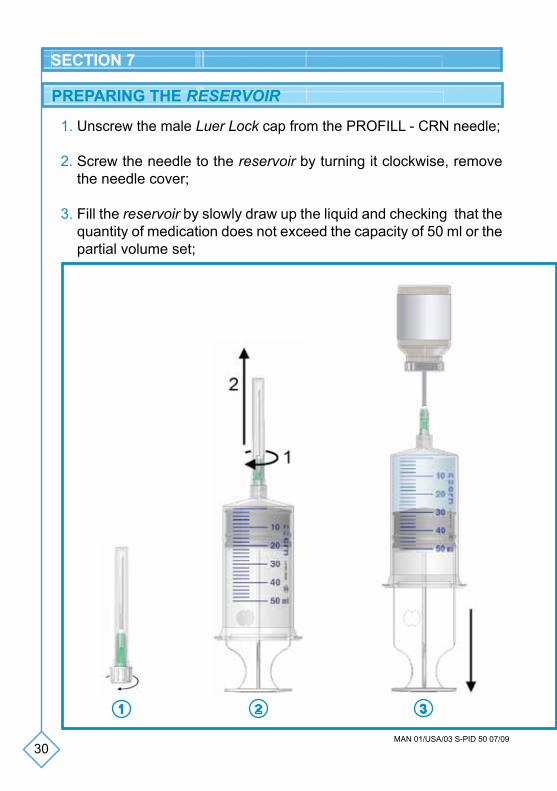
PREPARING THE RESERVOIR
1. Unscrew the male Luer Lock cap from the PROFILL - CRN needle;
2. Screw the needle to the reservoir by turning it clockwise, remove the needle cover;
3. Fill the reservoir by slowly draw up the liquid and checking that the quantity of medication does not exceed the capacity of 50 ml or the partial volume set;
31MAN 01/USA/03 S-PID 50 07/09
SECTION 7
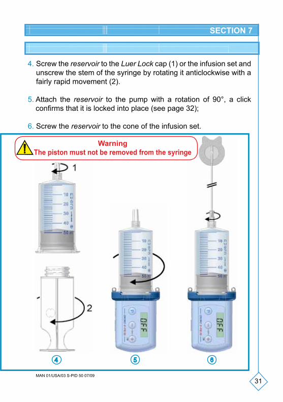
4. Screw the reservoir to the Luer Lock cap (1) or the infusion set and unscrew the stem of the syringe by rotating it anticlockwise with a fairly rapid movement (2).
5. Attach the reservoir to the pump with a rotation of 90°, a click confirms that it is locked into place (see page 32);
6. Screw the reservoir to the cone of the infusion set.
WarningThe piston must not be removed from the syringe
32MAN 01/USA/03 S-PID 50 07/09
SECTION 7
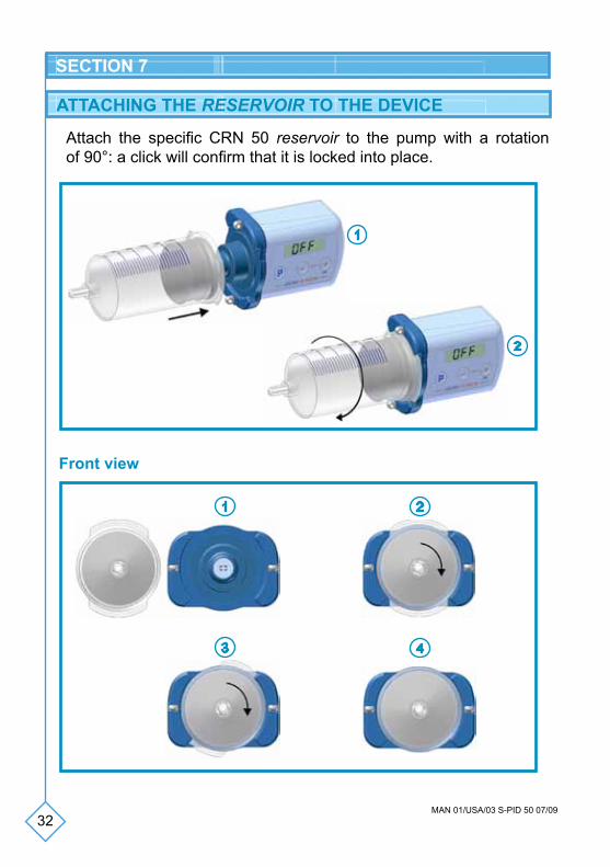
Attach the specific CRN 50 reservoir to the pump with a rotation of 90°: a click will confirm that it is locked into place.
Front view
ATTACHING THE RESERVOIR TO THE DEVICE

33MAN 01/USA/03 S-PID 50 07/09
SECTION 7
1 - Before filling the reservoir
Unscrew the stem from the piston and screw it back onto the stem to facilitate unscrewing after filling the reservoir.
Slide the piston across the syringe body a couple of times to distribute the lubricant along the walls.
Detach the Luer Lock cap from the stem.
2 - Filling the reservoir
The liquid must be draw up slowly.
The reservoir must not be filled beyond the maximum volume allowed of 50 ml.
The stem must be unscrewed with a fairly rapid movement.
WARNING
34MAN 01/USA/03 S-PID 50 07/09
SECTION 7
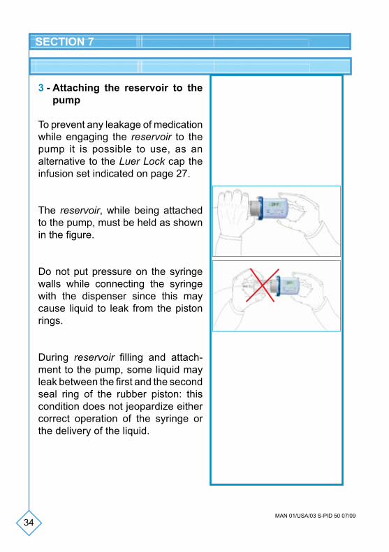
3 - Attaching the reservoir to the pump
To prevent any leakage of medication while engaging the reservoir to the pump it is possible to use, as an alternative to the Luer Lock cap the infusion set indicated on page 27.
The reservoir, while being attached to the pump, must be held as shown in the figure.
Do not put pressure on the syringe walls while connecting the syringe with the dispenser since this may cause liquid to leak from the piston rings.
During reservoir filling and attach-ment to the pump, some liquid may leak between the first and the second seal ring of the rubber piston: this condition does not jeopardize either correct operation of the syringe or the delivery of the liquid.
Function/operation Pushbuttons
Switching the pump on
Switching the pump off +
End (OFF) P +
Infusion number display (7 seconds)
Flow rate switching/infusion duration (ON)
Prime function* P
35MAN 01/USA/03 S-PID 50 07/09
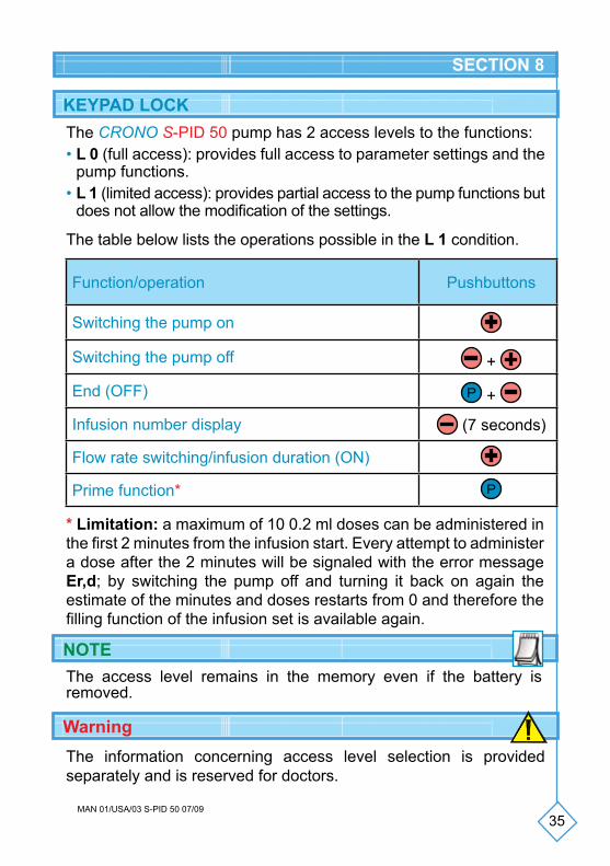
The CRONO S-PID 50 pump has 2 access levels to the functions:• L 0 (full access): provides full access to parameter settings and the
pump functions.• L 1 (limited access): provides partial access to the pump functions but
does not allow the modification of the settings.
* Limitation: a maximum of 10 0.2 ml doses can be administered in the first 2 minutes from the infusion start. Every attempt to administer a dose after the 2 minutes will be signaled with the error message Er,d; by switching the pump off and turning it back on again the estimate of the minutes and doses restarts from 0 and therefore the filling function of the infusion set is available again.
The access level remains in the memory even if the battery is removed.
The information concerning access level selection is provided separately and is reserved for doctors.
KEYPAD LOCK
Warning
NOTE
SECTION 8
The table below lists the operations possible in the L 1 condition.
Function/operation Pushbuttons
Switching the pump on
Switching the pump off +
End (OFF) P +
Infusion number display (7 seconds)
Flow rate switching/infusion duration (ON)
Prime function* P
36MAN 01/USA/03 S-PID 50 07/09
INITIALIZATION OF THE PUMP
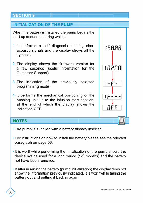
When the battery is installed the pump begins the start up sequence during which:
1. It performs a self diagnosis emitting short acoustic signals and the display shows all the symbols.
2. The display shows the firmware version for a few seconds (useful information for the Customer Support).
3. The indication of the previously selected programming mode.
4. It performs the mechanical positioning of the pushing unit up to the infusion start position, at the end of which the display shows the indication OFF.
10
20
• The pump is supplied with a battery already inserted.
• For instructions on how to install the battery please see the relevant paragraph on page 56.
• It is worthwhile performing the initialization of the pump should the device not be used for a long period (1-2 months) and the battery not have been removed.
• If after inserting the battery (pump initialization) the display does not show the information previously indicated, it is worthwhile taking the battery out and putting it back in again.
NOTES
SECTION 9
10
20
10
20
10
20
37MAN 01/USA/03 S-PID 50 07/09
SETTING AND INSERTING THE BATTERY
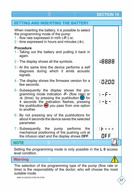
When inserting the battery, it is possible to select the programming mode of the pump:1 - flow rate expressed in ml/h (-F-) or,2 - time expressed in hours and minutes (-t-).
Procedure1 - Taking out the battery and putting it back in
again.2 - The display shows all the symbols.3 - At the same time the device performs a self
diagnosis during which it emits acoustic signals.
4 - The display shows the firmware version for a few seconds.
5 - Subsequently the display shows the pro-gramming mode indication -F- (flow rate) or -t- (time): by pressing the pushbutton P for 4 seconds the indication flashes, pressing the pushbutton you pass from one option to another.
6 - By not pressing any of the pushbuttons for about 4 seconds the device saves the selected parameter.
7 - Subsequently the pump performs the mechanical positioning of the pushing unit at the infusion start and the display shows OFF.
WarningThe selection of the programming type of the pump (flow rate or time) is the responsibility of the doctor, who will choose the most suitable mode.
10
20
10
20
10
20
10
20
SECTION 10
10
20
Setting the programming mode is only possible in the L 0 access level condition.
NOTE
38MAN 01/USA/03 S-PID 50 07/09
In the OFF condition the following parameters can be set:1 - Infusion end acoustic signal2 - Number of infusion points (function in flow
rate mode only)3 - Partial volume
The selection of the parameters in the OFF condition may be performed only in the following conditions:- pump OFF;- keypad unlocked;- at the start of a new infusion (partial or total).
To access the settings press the pushbutton P for about 1 second: the display shows the setting phase of the infusion end acoustic signal. Varying the setting of the parameter is possible (activation/deactivation) while the value on the display flashes by using the pushbuttons and .
By pressing the pushbutton P again the display shows the setting phase of the number of infusion points. Varying the setting of the parameter is possible while the value on the display flashes by using the pushbuttons and .
By pressing the pushbutton P again the display shows the setting phase of the partial volume. Varying the setting of the parameter is possible while the value on the display flashes by using the pushbuttons and .
SETTINGS IN THE OFF CONDITION
SECTION 10
39MAN 01/USA/03 S-PID 50 07/09
10
20
10
20
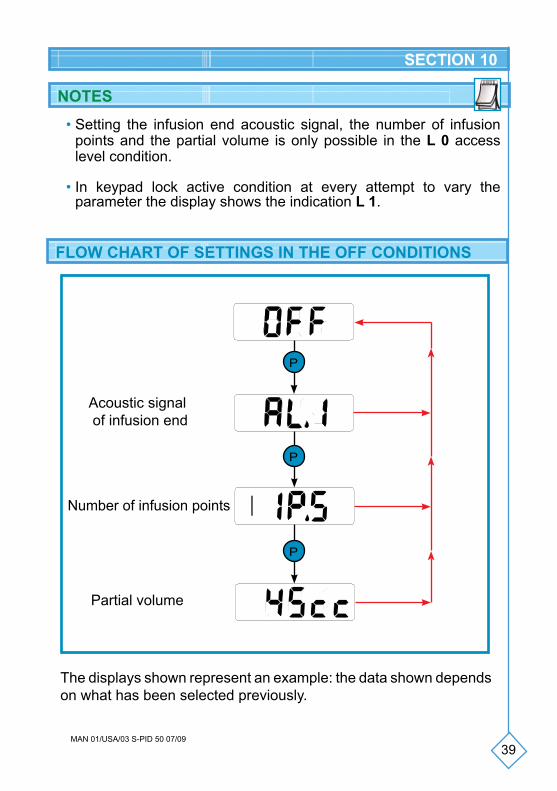
The displays shown represent an example: the data shown depends on what has been selected previously.
P
Acoustic signal of infusion end
Number of infusion points
Partial volume
P
SECTION 10
• Setting the infusion end acoustic signal, the number of infusion points and the partial volume is only possible in the L 0 access level condition.
• In keypad lock active condition at every attempt to vary the parameter the display shows the indication L 1.
NOTES
FLOW CHART OF SETTINGS IN THE OFF CONDITIONS
P
40MAN 01/USA/03 S-PID 50 07/09
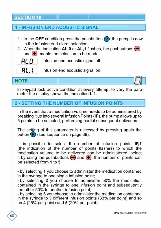
1 - In the OFF condition press the pushbutton P : the pump is now in the infusion end alarm selection.
2 - When the indication AL,0 or AL,1 flashes, the pushbuttons and enable the selection to be made.
1 - INFUSION END ACOUSTIC SIGNAL
Infusion end acoustic signal off.
Infusion end acoustic signal on.
SECTION 10
In the event that a medication volume needs to be administered by breaking it up into several Infusion Points (IP), the pump allows up to 5 points to be selected, performing partial subsequent deliveries.
The setting of this parameter is accessed by pressing again the button P (see sequence on page 39).
It is possible to select the number of infusion points IP,1 (the indication of the number of points flashes) to which the medication volume to be delivered can be administered; select it by using the pushbuttons and ; the number of points can be selected from 1 to 5:
- by selecting 1 you choose to administer the medication contained in the syringe to one single infusion point;- by selecting 2 you choose to administer 50% the medication contained in the syringe to one infusion point and subsequently the other 50% to another infusion point;- by selecting 3 you choose to administer the medication contained in the syringe to 3 different infusion points (33% per point) and so on 4 (25% per point) and 5 (20% per point).
2 - SETTING THE NUMBER OF INFUSION POINTS
NOTE
In keypad lock active condition at every attempt to vary the para-meter the display shows the indication L 1.
41MAN 01/USA/03 S-PID 50 07/09
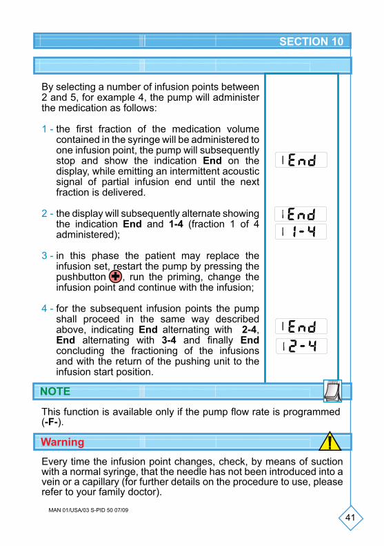
By selecting a number of infusion points between 2 and 5, for example 4, the pump will administer the medication as follows:
1 - the first fraction of the medication volume contained in the syringe will be administered to one infusion point, the pump will subsequently stop and show the indication End on the display, while emitting an intermittent acoustic signal of partial infusion end until the next fraction is delivered.
2 - the display will subsequently alternate showing the indication End and 1-4 (fraction 1 of 4 administered);
3 - in this phase the patient may replace the infusion set, restart the pump by pressing the pushbutton , run the priming, change the infusion point and continue with the infusion;
4 - for the subsequent infusion points the pump shall proceed in the same way described above, indicating End alternating with 2-4, End alternating with 3-4 and finally End concluding the fractioning of the infusions and with the return of the pushing unit to the infusion start position.
This function is available only if the pump flow rate is programmed (-F-).
NOTE
10
10
20
10
20
SECTION 10
10
10
Warning
Every time the infusion point changes, check, by means of suction with a normal syringe, that the needle has not been introduced into a vein or a capillary (for further details on the procedure to use, please refer to your family doctor).
42MAN 01/USA/03 S-PID 50 07/09
3 - SETTING THE PARTIAL VOLUME
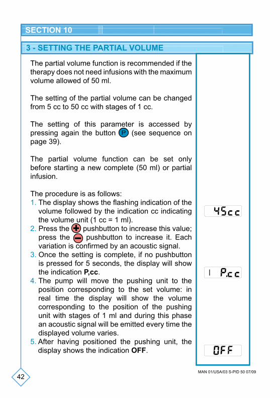
The partial volume function is recommended if the therapy does not need infusions with the maximum volume allowed of 50 ml.
The setting of the partial volume can be changed from 5 cc to 50 cc with stages of 1 cc.
The setting of this parameter is accessed by pressing again the button P (see sequence on page 39).
The partial volume function can be set only before starting a new complete (50 ml) or partial infusion.
The procedure is as follows:1. The display shows the flashing indication of the
volume followed by the indication cc indicating the volume unit (1 cc = 1 ml).
2. Press the pushbutton to increase this value; press the pushbutton to increase it. Each variation is confirmed by an acoustic signal.
3. Once the setting is complete, if no pushbutton is pressed for 5 seconds, the display will show the indication P,cc.
4. The pump will move the pushing unit to the position corresponding to the set volume: in real time the display will show the volume corresponding to the position of the pushing unit with stages of 1 ml and during this phase an acoustic signal will be emitted every time the displayed volume varies.
5. After having positioned the pushing unit, the display shows the indication OFF.
10
20
10
20
SECTION 10

43MAN 01/USA/03 S-PID 50 07/09
• The value of the partial volume set is automatically saved by the pump.
• At the end of an infusion, the pushing unit withdraws to the position corresponding to the selected partial volume.
• The partial volume function may be interrupted by pressing the pushbuttons and at the same time: the device switches itself off (the display reads OFF) and the pushing unit remains in the position in which the interruption took place.
If the partial volume is lower than the set volume (the pushing unit progresses): the partial volume is not saved in the memory and the previously set one remains active.If the partial volume is higher than the set volume (the pushing unit withdraws): the display shows OFF alternating with P,cc. The only possible operation is to restore the withdrawal by pressing the pushbutton . The pushing unit continues its withdrawal towards the set partial volume.
• This operation must be performed with the infusion set disconnec-ted from the reservoir.
• A partial volume can not be set during an infusion.
• The setting of the partial volume remains in the memory until the battery is removed: upon inserting the battery the partial volume is always set to 50 ml.
NOTES
Warning
SECTION 10
44MAN 01/USA/03 S-PID 50 07/09
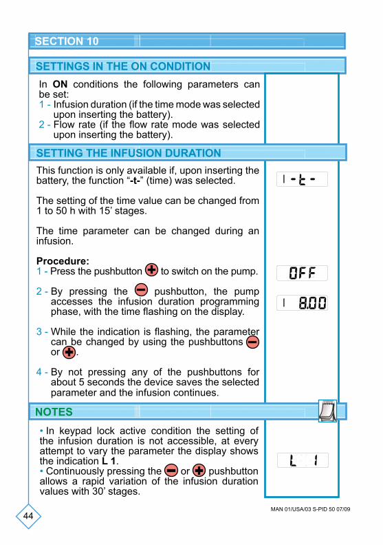
In ON conditions the following parameters can be set: 1 - Infusion duration (if the time mode was selected
upon inserting the battery).2 - Flow rate (if the flow rate mode was selected
upon inserting the battery).
SETTINGS IN THE ON CONDITION
10
20
SECTION 10
NOTES• In keypad lock active condition the setting of the infusion duration is not accessible, at every attempt to vary the parameter the display shows the indication L 1.• Continuously pressing the or pushbutton allows a rapid variation of the infusion duration values with 30’ stages.
This function is only available if, upon inserting the battery, the function “-t-” (time) was selected.
The setting of the time value can be changed from 1 to 50 h with 15’ stages.
The time parameter can be changed during an infusion.
Procedure:1 - Press the pushbutton to switch on the pump.
2 - By pressing the pushbutton, the pump accesses the infusion duration programming phase, with the time flashing on the display.
3 - While the indication is flashing, the parameter can be changed by using the pushbuttons or .
4 - By not pressing any of the pushbuttons for about 5 seconds the device saves the selected parameter and the infusion continues.
10
20
SETTING THE INFUSION DURATION
45MAN 01/USA/03 S-PID 50 07/09
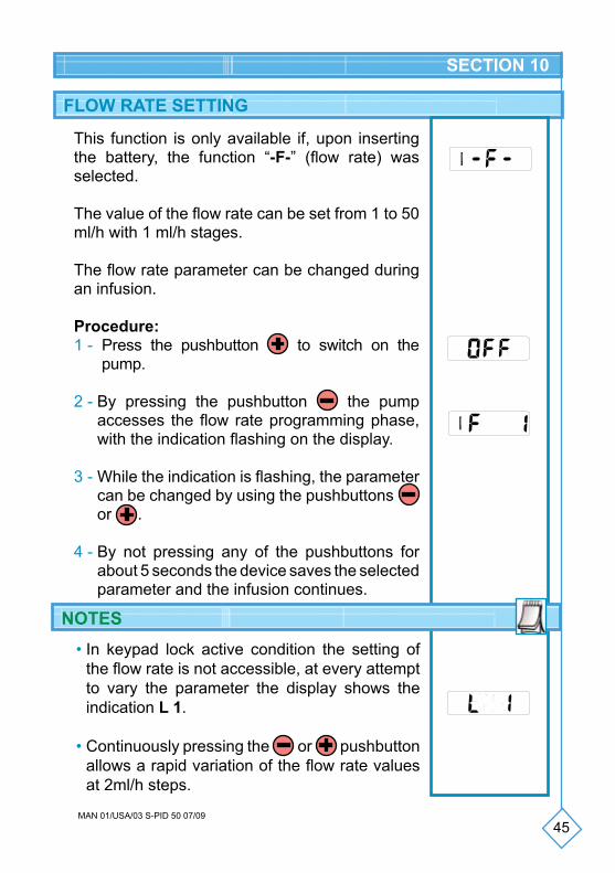
This function is only available if, upon inserting the battery, the function “-F-” (flow rate) was selected.
The value of the flow rate can be set from 1 to 50 ml/h with 1 ml/h stages.
The flow rate parameter can be changed during an infusion.
Procedure:1 - Press the pushbutton to switch on the
pump.
2 - By pressing the pushbutton the pump accesses the flow rate programming phase, with the indication flashing on the display.
3 - While the indication is flashing, the parameter can be changed by using the pushbuttons or .
4 - By not pressing any of the pushbuttons for about 5 seconds the device saves the selected parameter and the infusion continues.
FLOW RATE SETTING
10
20
SECTION 10
NOTES• In keypad lock active condition the setting of
the flow rate is not accessible, at every attempt to vary the parameter the display shows the indication L 1.
• Continuously pressing the or pushbutton allows a rapid variation of the flow rate values at 2ml/h steps.
10
20
46MAN 01/USA/03 S-PID 50 07/09
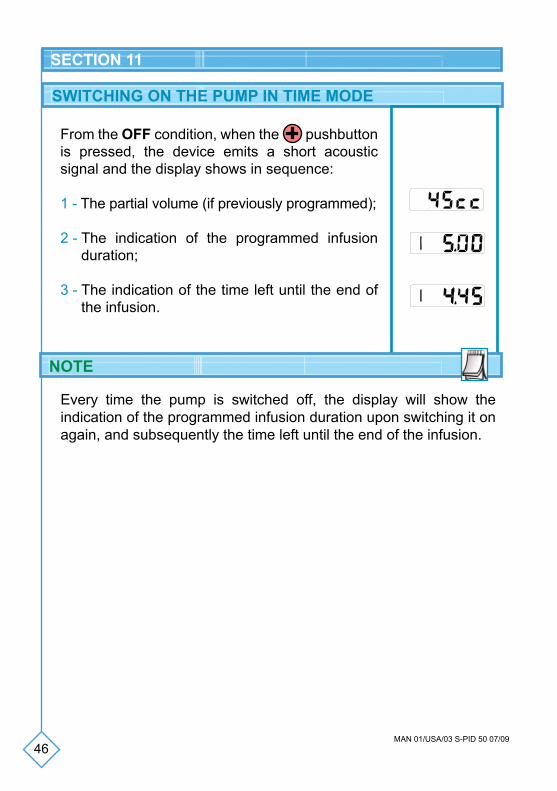
SWITCHING ON THE PUMP IN TIME MODE
From the OFF condition, when the pushbutton is pressed, the device emits a short acoustic signal and the display shows in sequence:
1 - The partial volume (if previously programmed);
2 - The indication of the programmed infusion duration;
3 - The indication of the time left until the end of the infusion.
Every time the pump is switched off, the display will show the indication of the programmed infusion duration upon switching it on again, and subsequently the time left until the end of the infusion.
NOTE
10
20
10
20
SECTION 11
10
20
47MAN 01/USA/03 S-PID 50 07/09
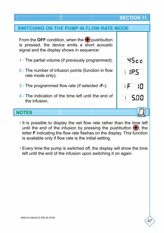
SWITCHING ON THE PUMP IN FLOW RATE MODE
From the OFF condition, when the pushbutton is pressed, the device emits a short acoustic signal and the display shows in sequence:
1 - The partial volume (if previously programmed);
2 - The number of infusion points (function in flow rate mode only);
3 - The programmed flow rate (if selected -F-);
4 - The indication of the time left until the end of the infusion.
10
20
10
20
10
20
10
20
• It is possible to display the set flow rate rather than the time left until the end of the infusion by pressing the pushbutton ; the letter F indicating the flow rate flashes on the display. This function is available only if flow rate is the initial setting.
• Every time the pump is switched off, the display will show the time left until the end of the infusion upon switching it on again.
NOTES
SECTION 11
48MAN 01/USA/03 S-PID 50 07/09
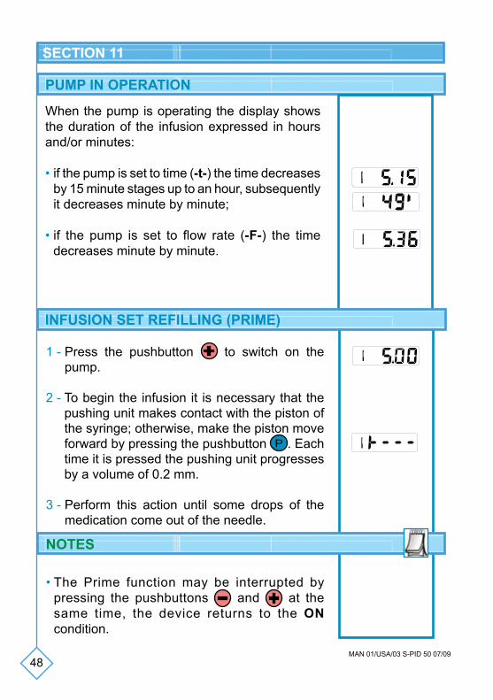
PUMP IN OPERATION
When the pump is operating the display shows the duration of the infusion expressed in hours and/or minutes:
• if the pump is set to time (-t-) the time decreases by 15 minute stages up to an hour, subsequently it decreases minute by minute;
• if the pump is set to flow rate (-F-) the time decreases minute by minute.
10
20
10
20
1 - Press the pushbutton to switch on the pump.
2 - To begin the infusion it is necessary that the pushing unit makes contact with the piston of the syringe; otherwise, make the piston move forward by pressing the pushbutton P . Each time it is pressed the pushing unit progresses by a volume of 0.2 mm.
3 - Perform this action until some drops of the medication come out of the needle.
• The Prime function may be interrupted by pressing the pushbuttons and at the same time, the device returns to the ON condition.
INFUSION SET REFILLING (PRIME)
10
20
10
20
10
20
NOTES
SECTION 11
49MAN 01/USA/03 S-PID 50 07/09
SECTION 11
• If the keypad is locked, a maximum of 10 0.2 ml doses can be administered in the first 2 minutes from the infusion start. Every attempt to administer a dose after the 2 minutes will be denied and signaled with the error message Er,d; by switching the pump off and turning it back on again the estimate of the minutes and doses restarts from 0 and therefore the filling function of the infusion set is available again.
This function allows the infusion line to be filled in case the infusion set needs to be replaced.

50MAN 01/USA/03 S-PID 50 07/09
WITHDRAWAL
1 - Total anticipated withdrawalThe infusion in progress can be interrupted and the pushing unit returned to the position it was in at infusion start.
To perform a total withdrawal, proceed as follows:• Switch the pump off by pressing the push-
buttons and at the same time.• Press the pushbuttons P and at the same
time, the display shows End for 10 seconds and subsequently starts the withdrawal of the pushing unit.
2 - Infusion end withdrawalIf AL,1 is set (active infusion end acoustic signal) at the end of the infusion a continuous acoustic signal is emitted and the display shows the message End.The pushing unit automatically returns to the position it was in at infusion start in the OFF condition.
When the pushing unit performs a continuous withdrawal movement, the symbol “Continuous pushing unit withdrawal” appears on the display.
10
10
10
20
SECTION 11
PUSHING UNIT MOVEMENT
51MAN 01/USA/03 S-PID 50 07/09
SECTION 11
NOTES
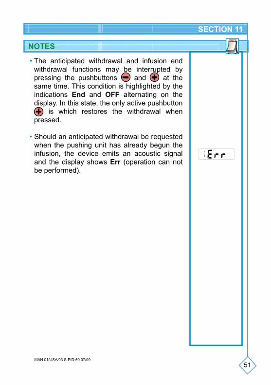
• The anticipated withdrawal and infusion end withdrawal functions may be interrupted by pressing the pushbuttons and at the same time. This condition is highlighted by the indications End and OFF alternating on the display. In this state, the only active pushbutton
is which restores the withdrawal when pressed.
• Should an anticipated withdrawal be requested when the pushing unit has already begun the infusion, the device emits an acoustic signal and the display shows Err (operation can not be performed).
10
20
52MAN 01/USA/03 S-PID 50 07/09
POST-OCCLUSION BOLUS
OCCLUSION
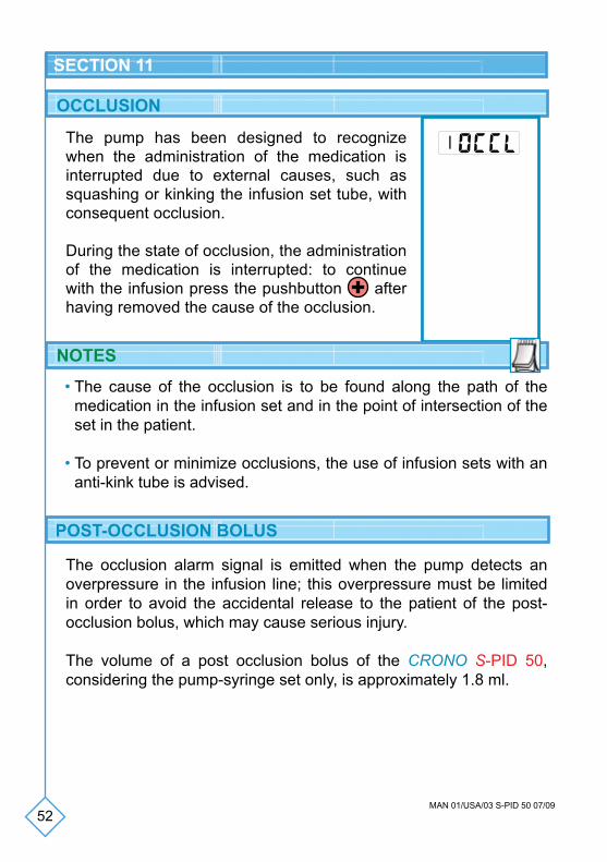
The pump has been designed to recognize when the administration of the medication is interrupted due to external causes, such as squashing or kinking the infusion set tube, with consequent occlusion.
During the state of occlusion, the administration of the medication is interrupted: to continue with the infusion press the pushbutton after having removed the cause of the occlusion.
The occlusion alarm signal is emitted when the pump detects an overpressure in the infusion line; this overpressure must be limited in order to avoid the accidental release to the patient of the post-occlusion bolus, which may cause serious injury.
The volume of a post occlusion bolus of the CRONO S-PID 50, considering the pump-syringe set only, is approximately 1.8 ml.
10
20
NOTES
• The cause of the occlusion is to be found along the path of the medication in the infusion set and in the point of intersection of the set in the patient.
• To prevent or minimize occlusions, the use of infusion sets with an anti-kink tube is advised.
SECTION 11
53MAN 01/USA/03 S-PID 50 07/09
SECTION 11
Warning
• The volume of the bolus released after a condition of occlusion may vary depending on the type of catheter, the infusion set and all the elements in the infusion line.
• Another element that may affect the volume of the bolus released after a condition of occlusion is the possible presence of air in the system.
• After an occlusion has been signaled, if necessary, take adequate measures to prevent the administration of a post-occlusion bolus to the patient.
INFUSION END
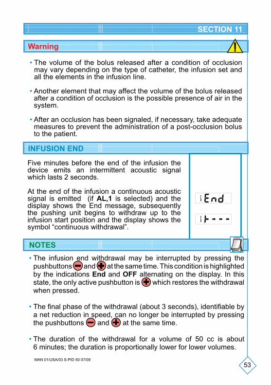
Five minutes before the end of the infusion the device emits an intermittent acoustic signal which lasts 2 seconds.
At the end of the infusion a continuous acoustic signal is emitted (if AL,1 is selected) and the display shows the End message, subsequently the pushing unit begins to withdraw up to the infusion start position and the display shows the symbol “continuous withdrawal”.
10
10
20
NOTES• The infusion end withdrawal may be interrupted by pressing the
pushbuttons and at the same time. This condition is highlighted by the indications End and OFF alternating on the display. In this state, the only active pushbutton is which restores the withdrawal when pressed.
• The final phase of the withdrawal (about 3 seconds), identifiable by a net reduction in speed, can no longer be interrupted by pressing the pushbuttons and at the same time.
• The duration of the withdrawal for a volume of 50 cc is about 6 minutes; the duration is proportionally lower for lower volumes.
54MAN 01/USA/03 S-PID 50 07/09
SECTION 11
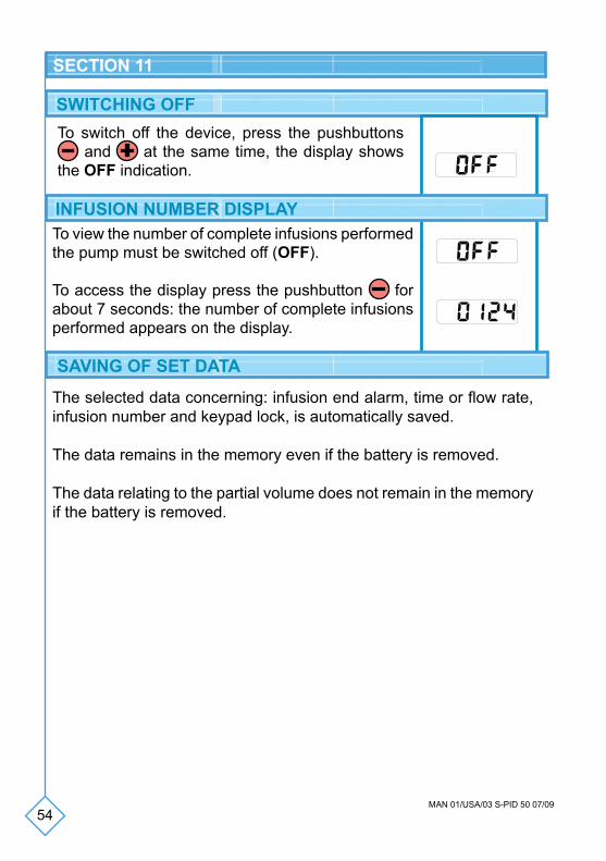
SWITCHING OFFTo switch off the device, press the pushbuttons
and at the same time, the display shows the OFF indication.
INFUSION NUMBER DISPLAY
��
��
To view the number of complete infusions performed the pump must be switched off (OFF).
To access the display press the pushbutton for about 7 seconds: the number of complete infusions performed appears on the display.
SAVING OF SET DATA
The selected data concerning: infusion end alarm, time or flow rate, infusion number and keypad lock, is automatically saved.
The data remains in the memory even if the battery is removed.
The data relating to the partial volume does not remain in the memory if the battery is removed.
55MAN 01/USA/03 S-PID 50 07/09
BATTERY LOW WARNING
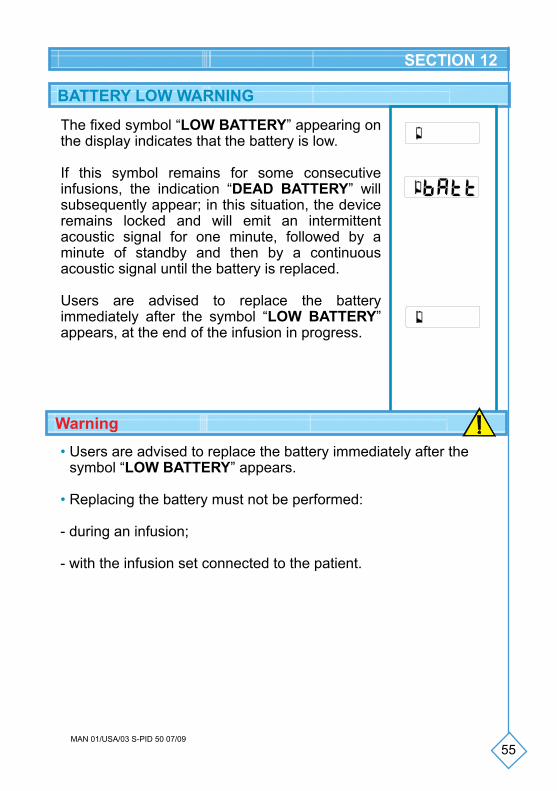
The fixed symbol “LOW BATTERY” appearing on the display indicates that the battery is low.
If this symbol remains for some consecutive infusions, the indication “DEAD BATTERY” will subsequently appear; in this situation, the device remains locked and will emit an intermittent acoustic signal for one minute, followed by a minute of standby and then by a continuous acoustic signal until the battery is replaced.
Users are advised to replace the battery immediately after the symbol “LOW BATTERY” appears, at the end of the infusion in progress.
SECTION 12
• Users are advised to replace the battery immediately after the symbol “LOW BATTERY” appears.
• Replacing the battery must not be performed:
- during an infusion;
- with the infusion set connected to the patient.
Warning
56MAN 01/USA/03 S-PID 50 07/09
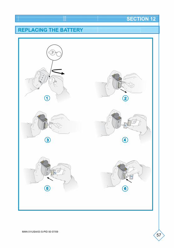
REPLACING THE BATTERY
1. Open the battery compartment door with the opener or with a paperclip;
2. Remove the cover;
3. Pull the strip of cloth located under the battery, to remove the battery;
4. Take out the dead battery;
5. Insert the new battery respecting the polarity indicated and taking care to place the extraction strip underneath it;
6. After inserting the battery, close the compartment door.
Should it not be possible to extract the battery with the strip, do not use another object and proceed as follows:
• Hold the device firmly in your right hand;
• Gently tap the palm of your left with your right hand to make the battery come out.
SECTION 12
NOTES
• After inserting the battery, the battery performs a self diagnosis during which it emits short acoustic signals and the display shows all the symbols.
• In normal conditions of use, the battery’s life is around 3/6 months or 60-80 infusions.
• During the replacement of the battery, the pump stores the data set in the memory; the only data not saved concerns any partial volume programming.
• Make sure that the battery compartment door is correctly closed.
• The door is fitted with a silicone seal that must remain in its lodging.
57MAN 01/USA/03 S-PID 50 07/09
REPLACING THE BATTERY
CR
ON
O P
ID
CR
ON
O P
ID
CRONO PID
CRONO PID
SECTION 12
58MAN 01/USA/03 S-PID 50 07/09
BATTERY CARE
• Only use 3 Volt Lithium batteries model CR 123 A.
• Using other batteries may cause the device to malfunction.
• The above mentioned batteries are available in all good photographic stores.
• Do not use rechargeable batteries.
• In normal conditions of use, the battery’s life is around 3/6 months - 60/80 infusions. It is worthwhile keeping a backup battery.
• The battery’s life can be influenced by its age, storage method and temperature.
• In the case that the device is not used for long periods, it is worth removing the battery from its compartment.
• Always make sure that the battery compartment door is closed correctly.
• Used batteries must be disposed of appropriately by using specific containers.
SECTION 12
59MAN 01/USA/03 S-PID 50 07/09
GENERAL WARNINGS
SECTION 13
• The device can be damaged by infiltration of liquids, therefore it must not be used while having a bath, a shower, etc. Should liquid accidentally penetrate the device (e.g. drops of medication), it is necessary to have it checked by CANè S.p.A.’s Assistance Center.
• The device must be kept away from:- heat sources (radiators, ovens, heaters);- direct sunlight (the fabric case is not adequate protection);- intense electromagnetic fields (magnets, speakers, car radio
equipment), details are provided in ATTACHMENT 3;- ionizing radiation;- ultrasound devices;- magnetic resonance devices.
• The device does not need to be sterilized.
• Do not freeze the CRN syringes with medication inside.
• The device must not be placed in a fridge or freezer.
• The device must not be placed in an oven or microwave.
Not respecting the indications stated in the above mentioned warnings, the device may malfunction with serious consequences for the user.
60MAN 01/USA/03 S-PID 50 07/09
CLEANING
GENERAL WARNINGS
STORAGE
The technical characteristics of the device make the amount of maintenance required extremely low.
If the device is damaged, we recommend having it checked by the CANè S.p.A. Customer Support before using it again.
The external surfaces can be cleaned using a slightly damp soft cloth with some mild detergent or disinfectant.
• Do not immerse the pump in detergent solutions or in water.• Avoid infiltrations of liquids inside the pump. Should the device get
wet, dry it immediately with paper towels.• Do not clean the pump with acetone, solvents or abrasive
detergents. • Do not sterilize the pump.
If the device is not used for a period exceeding 2/3 months, we advise removing the battery and placing it inside its case in a dry place at room temperature.
SECTION 14
MANUAL UPDATES
The version and the publication date of this instruction manual are reported on every page of the document. If a year passes from the publication date (reported on page 2) and the product being used, the doctor must contact CANè S.p.A. to check if there is a more recent version of the manual.
MAINTENANCE
61MAN 01/USA/03 S-PID 50 07/09
EXPECTED LIFE OF THE PUMP
DISPOSAL
The expected life of the pump is 4 (four) years starting from the purchase date; for safety reasons, it must not be used after this period.
At the end of the life of the pump, contact the CANè S.p.A. Customer Support, which will provide the necessary indications for the collec-tion and disposal of the device.
Reservoirs, infusion set, needles, filters, and all the material used must be disposed of appropriately, by using specific containers.
SECTION 14
62MAN 01/USA/03 S-PID 50 07/09
SECTION 15
CUSTOMER SUPPORTThe device must only be repaired by the CANè S.p.A. Customer Support. Before sending the device we advise contacting:
• IntraPump Infusion Systems®
UNITED STATES920 Minters Chapel Road, Suite 200Grapevine, TX 76051Tel: 866-211-7867Fax: 630-845-2768Email: [email protected]• Customer Support ServiceCANè S.p.A. Medical TechnologyVia Cuorgnè, 42/a 10098 Rivoli (Turin) - ItalyTel. +39.011.9574872 - Fax +39.011.9598880Internet: www.canespa.it - E-mail: [email protected]
With this warranty CANè S.p.A. guarantees the product from any faults in materials or manufacturing faults for the duration of 2 (TWO) years starting from the original purchase date.
Should faults in materials or manufacturing faults be found during this warranty period, CANè S.p.A. shall repair or replace the faulty components under the terms and conditions stated below, without any charge for the costs of manpower or spare parts; the cost of sending the device to the CANè S.p.A. Customer Support shall remain on the Customer’s account.
CANè S.p.A. reserves the right to vary the characteristics or the model of its devices, with no obligation to make changes to already manufactured and sold devices.
Conditions:1. The warranty shall only apply if the fault is claimed within the terms
of the warranty.
WARRANTY REGULATIONS
63MAN 01/USA/03 S-PID 50 07/09
2. This warranty does not cover the costs and/or any faults due to modifications or adaptations made to the product, without prior written authorization issued by CANè S.p.A.
CANè S.p.A. declines any responsibility towards purchasers or third parties, which may concern people or objects due to improper use of the device, not intended use and due to non-compliance with the regulations reported in the instruction manual. The buyer undertakes to exempt CANè S.p.A. from any claim made by third parties concerning the above.
3. This warranty is void if the model indication or the serial number indicated on the product have been modified, deleted, removed or in any case made illegible.
4. The following is excluded from the warranty:• Periodic maintenance interventions;• Damage due to improper use, including but not limited to:- incorrect electrical power supply;- use of the product for purposes other those it is intended for;- repair interventions performed by unauthorized personnel or by the
Customer;• Unforeseeable and accidental events, such as falls and infiltration
of liquids;• Natural events and malicious or culpable actions;• The accessories provided with the pump.
5. CANè S.p.A. undertakes, for a period not exceeding 4 (four) years from the purchase date, to perform repairs to the device.
After this period CANè S.p.A. is exempt from the obligation to repair. CANè S.p.A. declines any responsibility towards purchasers or third parties, for damages which may occur during the use of the device after 4 (four) years from the purchase date.
6. After the warranty expires, assistance shall be provided by CANè S.p.A. which charges for the replaced components, manpower and transportation in force at the time.
SECTION 15
64MAN 01/USA/03 S-PID 50 07/09
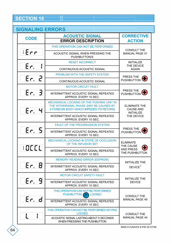
SIGNALING ERRORS
CODE ACOUSTIC SIGNALERROR DESCRIPTION
CORRECTIVEACTION
THIS OPERATION CAN NOT BE PERFORMED
ACOUSTIC SIGNAL WHEN PRESSING THE PUSHBUTTON/S
CONSULT THE MANUAL PAGE 51
RESET INCORRECT
CONTINUOUS ACOUSTIC SIGNAL
INITIALIzE THE DEVICE
AGAIN
PROBLEM WITH THE SAFETY SYSTEM
CONTINUOUS ACOUSTIC SIGNAL
MOTOR CIRCUIT FAULT
INTERMITTENT ACOUSTIC SIGNAL REPEATED APPROx. EVERY 10 SEC.
MECHANICAL LOCKING OF THE PUSHING UNIT IN THE WITHDRAWAL PHASE (MAY BE CAUSED BY A FOREIGN BODY WHICH IMPEDES ITS RETURN)
INTERMITTENT ACOUSTIC SIGNAL REPEATED APPROx. EVERY 10 SEC.
ELIMINATE THE CAUSE AND INITIALIzE
THE DEVICE
FAULT OF THE PROGRESSION SYSTEM
INTERMITTENT ACOUSTIC SIGNAL REPEATED APPROx. EVERY 10 SEC.
MECHANICAL LOCKING IN STATE OF OCCLUSION OF THE INFUSION SET
INTERMITTENT ACOUSTIC SIGNAL REPEATED APPROx. EVERY 10 SEC.
MEMORY READING ERROR (EEPROM)
INTERMITTENT ACOUSTIC SIGNAL REPEATED APPROx. EVERY 10 SEC.
INITIALIzE THE
DEVICE*
MOTOR CIRCUIT SAFETY FAULT
INTERMITTENT ACOUSTIC SIGNAL REPEATED APPROx. EVERY 10 SEC.
INITIALIzE THE DEVICE
THIS OPERATION CAN NOT BE PERFORMED PUSHBUTTON P
LOCKED
INTERMITTENT ACOUSTIC SIGNAL REPEATED APPROx. EVERY 10 SEC.
CONSULT THE MANUAL PAGE 49
THIS OPERATION CAN NOT BE PERFORMED KEYPAD LOCKED
ACOUSTIC SIGNAL LASTING ABOUT 5 SECONDS WHEN PRESSING THE PUSHBUTTON
CONSULT THE MANUAL PAGE 44
10
20
PRESS THE PUSHBUTTON
PRESS THE PUSHBUTTON
PRESS THE PUSHBUTTON
ELIMINATETHE CAUSEAND PRESS THE PUSHBUTTON
SECTION 16
10
20
10
65MAN 01/USA/03 S-PID 50 07/09
SECTION 16
The error messages shown on the display are accompanied by an acoustic signal and the subsequent shutdown of the system.
• After the Er,8 signal and the subsequent initialization, the set parameters will be those set at the factory (see page 15): in this condition, it is therefore necessary to reprogram the parameters prescribed by the doctor.
• If after the corrective action or the initialization of the device, the error signal occurs again, stop using the pump and contact the technical assistance service.
*Warning
NOTE
To initialize the device take out the battery and reinsert it after approx. 10/15 seconds.
CUSTOMER SUPPORT SERVICE
For further information about the CRONO S-PID 50 pumpcontact:
IntraPump Infusion Systems®
UNITED STATES920 Minters Chapel Road, Suite 200Grapevine, TX 76051Tel: 866-211-7867Fax: 630-845-2768Email: [email protected]
66MAN 01/USA/03 S-PID 50 07/09
SECTION 17
INSTRUCTIONS IN SHORT
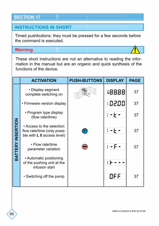
Timed pushbuttons: they must be pressed for a few seconds before the command is executed.
ACTIVATION PUSH-BUTTONS DISPLAY PAGE
• Display segment complete switching on
• Firmware version display
• Program type display (flow rate/time)
• Access to the selectionflow rate/time (only possi-ble with L 0 access level)
• Flow rate/timeparameter variation
• Automatic positioning of the pushing unit at the
infusion start
• Switching off the pump
BAT
TERY
INSE
RTI
ON
CR
ON
O PID
CRO
NO
PID
CRONO PID
CRONO PID
10
20
10
20
10
20
10
20
10
20
10
20P
Warning
These short instructions are not an alternative to reading the infor-mation in the manual but are an organic and quick synthesis of the functions of the device.
37
37
37
37
37
37
67MAN 01/USA/03 S-PID 50 07/09
SECTION 17
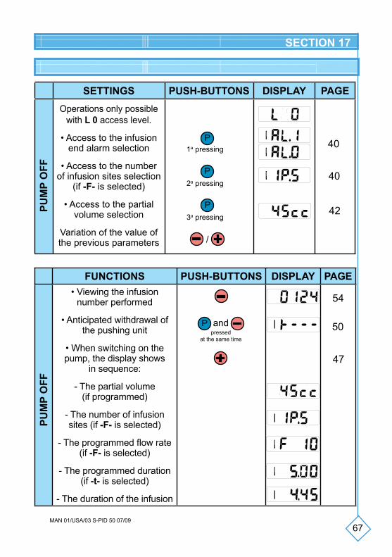
SETTINGS PUSH-BUTTONS DISPLAY PAGEOperations only possible
with L 0 access level.
• Access to the infusion end alarm selection
• Access to the number of infusion sites selection
(if -F- is selected)
• Access to the partial volume selection
Variation of the value of the previous parameters
PUM
P O
FF
P1a pressing
P2a pressing
P3a pressing
FUNCTIONS PUSH-BUTTONS DISPLAY PAGE• Viewing the infusion
number performed
• Anticipated withdrawal of the pushing unit
• When switching on the pump, the display shows
in sequence:
- The partial volume(if programmed)
- The number of infusion sites (if -F- is selected)
- The programmed flow rate(if -F- is selected)
- The programmed duration(if -t- is selected)
- The duration of the infusion
P and pressed
at the same time
PUM
P O
FF
10
20
10
20
10
20
10
20
/
��
��
10
20
10
20
10
20
40
40
42
54
50
47
10
20
10
20
10
20
68MAN 01/USA/03 S-PID 50 07/09
SECTION 17
FUNCTIONS PUSH-BUTTONS DISPLAY PAGE
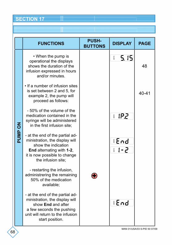
• When the pump is operational the displays
shows the duration of the infusion expressed in hours
and/or minutes.
• If a number of infusion sites is set between 2 and 5, for example 2, the pump will
proceed as follows:
- 50% of the volume of the medication contained in the syringe will be administered
in the first infusion site;
- at the end of the partial ad-ministration, the display will
show the indication End alternating with 1-2,
it is now possible to change the infusion site;
- restarting the infusion, administrering the remaining
50% of the medication available;
- at the end of the partial ad-ministration, the display will
show End and aftera few seconds the pushing
unit will return to the infusion start position.
PUM
P O
N
10
10
10
20
10
20
48
10
20
40-41
69MAN 01/USA/03 S-PID 50 07/09
SECTION 17
FUNCTIONS PUSH-BUTTONS DISPLAY PAGE
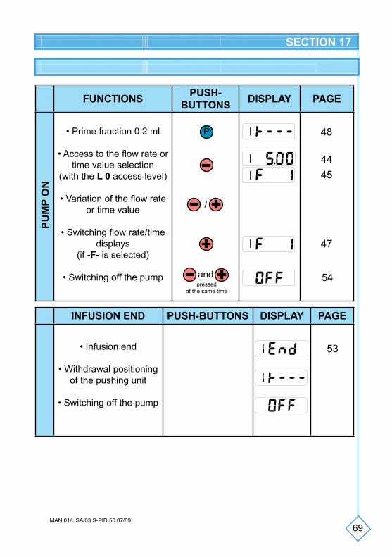
• Prime function 0.2 ml
• Access to the flow rate or time value selection
(with the L 0 access level)
• Variation of the flow rate or time value
• Switching flow rate/timedisplays
(if -F- is selected)
• Switching off the pump
P
PUM
P O
N
/
pressedat the same time
and
INFUSION END PUSH-BUTTONS DISPLAY PAGE
• Infusion end
• Withdrawal positioning of the pushing unit
• Switching off the pump
10
20
10
20
10
20
10
10
20
48
54
53
44
47
10
20
45
70MAN 01/USA/03 S-PID 50 07/09
SECTION 18
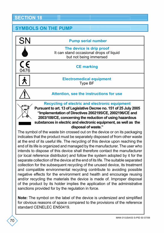
SYMBOLS ON THE PUMP
Pump serial number
The device is drip proofIt can stand occasional drops of liquid
but not being immersed
CE marking
Electromedical equipmentType BF
Attention, see the instructions for use
Recycling of electric and electronic equipmentPursuant to art. 13 of Legislative Decree no. 151 of 25 July 2005
“Implementation of Directives 2002195/CE, 2002196/CE and 2003/108/CE, concerning the reduction of using hazardous
substances in electric and electronic equipment, as well as the disposal of waste.”
SN
0476
The symbol of the waste bin crossed out on the device or on its packaging indicates that the product must be separately disposed of from other waste at the end of its useful life. The recycling of this device upon reaching the end of its life is organized and managed by the manufacturer. The user who intends to dispose of this device shall therefore contact the manufacturer (or local reference distributor) and follow the system adopted by it for the separate collection of the device at the end of its life. The suitable separated collection for the subsequent recycling of the unused device, its treatment and compatible environmental recycling contribute to avoiding possible negative effects for the environment and health and encourage reusing and/or recycling the materials the device is made of. Improper disposal of the product by its holder implies the application of the administrative sanctions provided for by the regulation in force.
Note: The symbol on the label of the device is undersized and simplified for obvious reasons of space compared to the provisions of the reference standard CENELEC EN50419.
71MAN 01/USA/03 S-PID 50 07/09
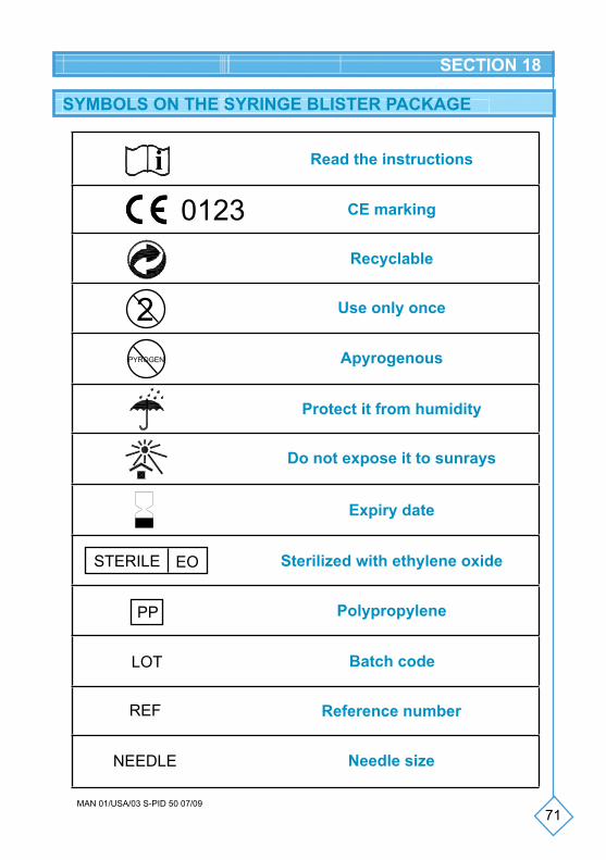
SYMBOLS ON THE SYRINGE BLISTER PACKAGE
SECTION 18
0123
i Read the instructions
CE marking
Recyclable
2PYROGEN
STERILE EO
PP
REF
LOT
NEEDLE
Use only once
Apyrogenous
Protect it from humidity
Do not expose it to sunrays
Expiry date
Sterilized with ethylene oxide
Polypropylene
Batch code
Reference number
Needle size
72MAN 01/USA/03 S-PID 50 07/09
SECTION 19
DECLARATION OF COMPLIANCE
0476CANÈ S.p.A. with offices in Via Cuorgnè, 42/a 10098 Rivoli (Turin) - Italy, manufacturer of the electromedical device portable medication syringe pump CRONO S-PID 50.
Serial numberManufacturing date
declares that the device conforms to the safety requirements pursuant to Attachment II, risk class IIb, of Directive 93/42/CEE of 14/6/1993 as certified by N. MED-9813 issued by the Notified Body 0476.
73MAN 01/USA/03 S-PID 50 07/09
ACCURACY TEST (TRUMPET CURVE)
ATTACHMENT 1
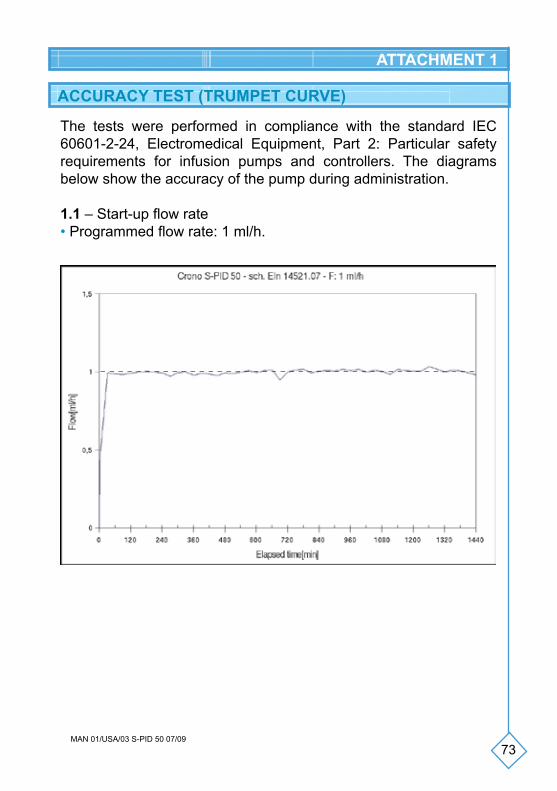
The tests were performed in compliance with the standard IEC 60601-2-24, Electromedical Equipment, Part 2: Particular safety requirements for infusion pumps and controllers. The diagrams below show the accuracy of the pump during administration.
1.1 – Start-up flow rate• Programmed flow rate: 1 ml/h.
74MAN 01/USA/03 S-PID 50 07/09
ATTACHMENT 1
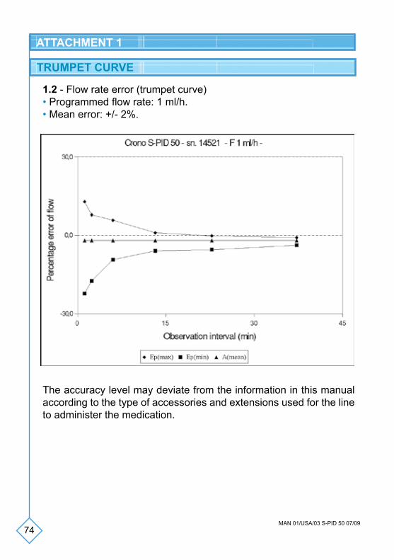
1.2 - Flow rate error (trumpet curve)• Programmed flow rate: 1 ml/h.• Mean error: +/- 2%.
The accuracy level may deviate from the information in this manual according to the type of accessories and extensions used for the line to administer the medication.
TRUMPET CURVE
75MAN 01/USA/03 S-PID 50 07/09
ATTACHMENT 2
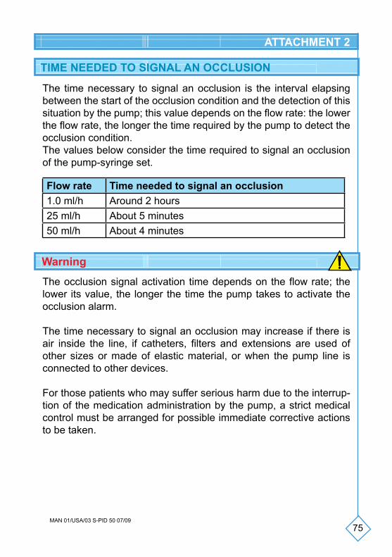
TIME NEEDED TO SIGNAL AN OCCLUSION
The time necessary to signal an occlusion is the interval elapsing between the start of the occlusion condition and the detection of this situation by the pump; this value depends on the flow rate: the lower the flow rate, the longer the time required by the pump to detect the occlusion condition. The values below consider the time required to signal an occlusion of the pump-syringe set.
Warning
The occlusion signal activation time depends on the flow rate; the lower its value, the longer the time the pump takes to activate the occlusion alarm.
The time necessary to signal an occlusion may increase if there is air inside the line, if catheters, filters and extensions are used of other sizes or made of elastic material, or when the pump line is connected to other devices.
For those patients who may suffer serious harm due to the interrup-tion of the medication administration by the pump, a strict medical control must be arranged for possible immediate corrective actions to be taken.
Flow rate Time needed to signal an occlusion1.0 ml/h Around 2 hours 25 ml/h About 5 minutes50 ml/h About 4 minutes

76MAN 01/USA/03 S-PID 50 07/09
ELECTROMAGNETIC COMPATIBILITY
At a glance and manufacturer’s statement - electromagnetic emissions
The CRONO S-PID 50 is designed to operate in the electromagnetic environment specified below. The customer or user of the CRONO S-PID 50 must guarantee that it will be used in such an environment.
Emission test Compliance Electromagneticenvironment - at a glance
Emissions in RF CISPR 11 Group 1
The CRONO S-PID 50 only uses RF energy for its internal operation. Consequently, its RF emissions are very low and, probably, do not cause any interference with electronic devices situated near it.
Emissions inRF CISPR 11 Class B
The CRONO S-PID 50 is suitable for use in all environments including the home and those linked directly to public low voltage electricity mains supply powering buildings used for housing purposes.
Harmonic emissionsIEC 61000-3-2
Not applicable
Emissions following voltage fluctuations/
flickering IEC 61000-3-3
Not applicable
The electromagnetic compatibility tests were performed in compli-ance with standards:
• IEC 60601-2-24:1998, Electromedical devices, Part 2: Special safety requirements for infusion pumps and controllers;
• CEI EN 60601-1-2 Ed. 2, Electromedical devices, Part 1: General safety requirements - Collateral standard: Electromagnetic compatibility - Requirements and tests.
ATTACHMENT 3

77MAN 01/USA/03 S-PID 50 07/09
ATTACHMENT 3
At a glance and manufacturer’s statement - electromagnetic immunity
The CRONO S-PID 50 is designed to operate in the electromagnetic environ-ment specified below. The customer or user of the CRONO S-PID 50 must gua-rantee that it will be used in such an environment.
Immunitytest
Test levelIEC 60601
Conformity level
Electromagneticenvironment - at a glance
Radiatedimmunity
80-1000 MHz 10V/m AM 80% 1 KHz 10V/m
20-80 MHz 10V/mAM 80% 1 KHz 10V/m
Interference was found near the devices marked with the following symbol:
At a glance and manufacturer’s statement - electromagnetic immunity
The CRONO S-PID 50 is designed to operate in the electromagnetic environment specified below. The customer or user of the CRONO S-PID 50 must guarantee that it will be used in such an environment.
Immunitytest
Testlevel
IEC 60601
Conformity level
Electromagnetic environment - at a glance
Electrostatic discharge (ESD) IEC 61000-4-2
15 kV in air8 kV acontact
15 kV in air8 kV acontact
The flooring must be made of wood, concrete or ceramics. If the flooring is coated with syntethic material, the relative humidity should be at least 30%.
78MAN 01/USA/03 S-PID 50 07/09
ATTACHMENT 3
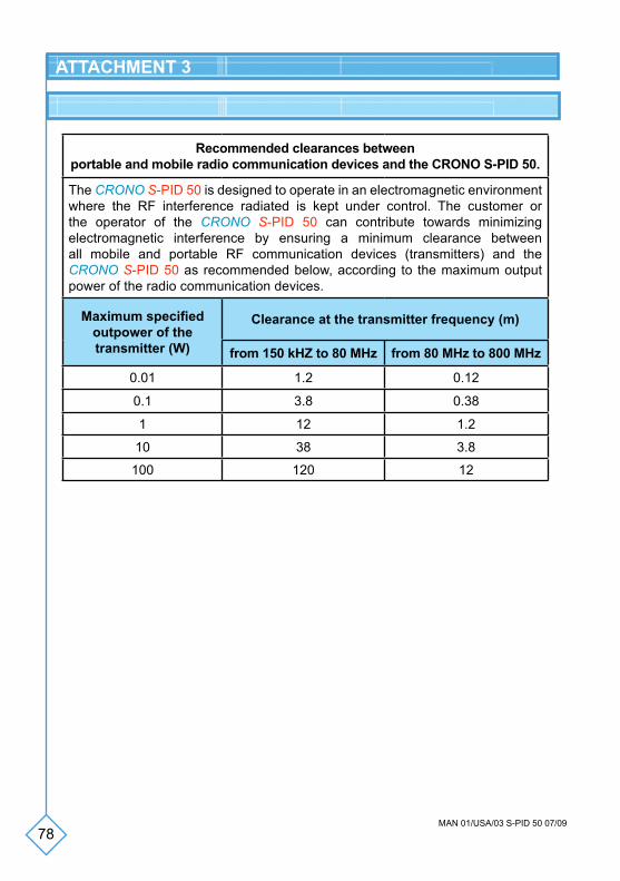
Recommended clearances betweenportable and mobile radio communication devices and the CRONO S-PID 50.
The CRONO S-PID 50 is designed to operate in an electromagnetic environment where the RF interference radiated is kept under control. The customer or the operator of the CRONO S-PID 50 can contribute towards minimizing electromagnetic interference by ensuring a minimum clearance between all mobile and portable RF communication devices (transmitters) and the CRONO S-PID 50 as recommended below, according to the maximum output power of the radio communication devices.
Maximum specified outpower of the transmitter (W)
Clearance at the transmitter frequency (m)
from 150 kHZ to 80 MHz from 80 MHz to 800 MHz
0.01 1.2 0.12
0.1 3.8 0.38
1 12 1.2
10 38 3.8
100 120 12
79MAN 01/USA/03 S-PID 50 07/09
INFORMATION
NOTES
For further information about the CRONO S-PID 50 pump contact:
IntraPump Infusion Systems®
UNITED STATES920 Minters Chapel Road, Suite 200Grapevine, TX 76051Tel: 866-211-7867Fax: 630-845-2768Email: [email protected]