USED WATER TREATMENT On-site Sanitation > 20 IE · • XP DTU 64.1 P1-2 : general criteria for...
32
On-site Sanitation > 20 IE • Water Treatment Plant with activated sludge • Tanks and decanters • Facilities for collective sanitation chain • Filtrapur USED WATER TREATMENT
Transcript of USED WATER TREATMENT On-site Sanitation > 20 IE · • XP DTU 64.1 P1-2 : general criteria for...

On-site Sanitation > 20 IE
• Water Treatment Plant with activated sludge• Tanks and decanters• Facilities for collective sanitation chain • Filtrapur
USED WATER TREATMENT
• Tanks and decanters• Facilities for collective sanitation chain

The document does not form part of any contract. The data is provided as an indication and may be changed without notice.
10 rue Richedoux 50480 SAINTE-MÈRE-ÉGLISE – FRANCE – Tél. +33 (0)2 33 95 88 00 – Fax +33 (0)2 33 21 50 75www.simop.com – e-mail : [email protected]
SIMOP
Principle of fi lament windingSIMOP’s many products are made of polyester which ensures high strength (high fi ber content from 60 to 70% and optimum fi ber arrangement facing the direction of the effort). This material also ensures a high resistance to corrosion. The manufacturing process used is the circumferential and helical fi lament winding. The method includes depositing the fi bers of polyester (roving wires) previously impregnated on a mandrel having a rotational movement. The manufacturing system is fully automated and allows us to control all production parameters (thickness, length ...) to ensure a fi nished product of the highest quality.The fi lament winding tanks gives excellent mechanical strength and consistency of the thickness of the tank.
Based on 35 years of experience, SIMOP positions itself as the market leader with its wide range and level of expertise in prefabricated solutions for the building and public works.
RotomouldingSimop has 35 years of experience in the manufacture of rotational molding.Our industrial equipment allows us to manufacture the larger single parts in Europe (35 m3).This ensures easy implementation and maintenance, perfect sealing of our devices and has the advantage of being recyclable.
An engineering performanceThe SIMOP engineering department impregnated with a strong spirit of innovation, is constantly at the forefront of new techniques and technologies. The intensity of its research and development allows him to continually develop existing products and regularly launch onto the market reliable and permanent solutions helping to improve environment.

Document non contractuel. Les cotes (en mm) sont données à titre indicatif et peuvent être modifi ées sans préavis. 1
10 rue Richedoux 50480 SAINTE-MÈRE-ÉGLISE – FRANCE – Tél. +33 (0)2 33 95 88 00 – Fax +33 (0)2 33 21 50 75www.simop.com – e-mail : [email protected]
SIMOP
Sheet N° PAGEOn site SanitationRegulations ......................................................................................................................................................... 2Summary guide for the calculation of water treatment facilities .......................................... 3
CHAINSChain ALL WATER TANK WITH SAND FILTER ............................................................................. 4Chain DECANTER DIGESTER WITH SAND FILTER .................................................................. 5Chain WITH ACTIVATED SLUDGE ......................................................................................................... 6Chain WITH FIXED CULTURE ................................................................................................................... 7Chain GREY WATER TREATMENT ....................................................................................................... 8
ALL WATER TANKS - DECANTERS DIGESTERSPolyethylene all water tanks for communities .................................... 6308 ...................... 9Polyester horizontal all water tanks ............................................................ 6313 ................... 10Polyester decanters digesters .......................................................................... 6320 ................... 11
OXYMOPPolyester primary decanter for OXYMOP ................................................. 6321 ................... 12Polyester OXYMOP ................................................................................................... 6334 ................... 13
FILTRAPURFILTRAPUR....................................................................................................................... 6344 ................... 14
GRISIMOPGRISIMOP ........................................................................................................................ 6070 ................... 15
ACCESSORIESSilt storages or polyethylene pre fi lters ..................................................... 6365 ................... 17Silt storages with fl oor and cleaning column ...................................... 6367 ................... 18Silt storages with HDPE rotproof cells ....................................................... 6368 ................... 19Polyethylene fl oating bucket ............................................................................. 6376 ................... 20Connecting Boxes / Effl uent distributor ...................................... 6060/6369 ................... 21Polythene grit chambers ...................................................................................... 6360 ................... 22Polycomposite grit chambers .......................................................................... 6362 ................... 23
INSTALLATION INSTRUCTIONS ......................................................................P050 ................... 24INSTALLATION INSTRUCTIONS ..................................................................... P053 ................... 25
GLOSSARY .......................................................................................................................................................... 26
A catalog On-site Sanitation < 20 IE is at your disposal.
SUMMARY
Document non contractuel. Les cotes (en mm) sont données à titre indicatif et peuvent être modifi ées sans préavis.2
10 rue Richedoux 50480 SAINTE-MÈRE-ÉGLISE – FRANCE – Tél. +33 (0)2 33 95 88 00 – Fax +33 (0)2 33 21 50 75www.simop.com – e-mail : [email protected]
SIMOP
Standards*•XP DTU 64.1 P1-1 : technical specifi cation requirements.
• XP DTU 64.1 P1-2 : general criteria for selection of materials.
• NF EN 12-566 : wastewater treatment small facilities up to 50 main rooms.
- NF EN 12-566-1 : prefabricated septic tanks.
- NF EN 12-566-3 : domestic wastewater treatment plant, ready for use and/or assembled on site.
Regulations*- Order dated June 22 2007 concerning collection, transport and treatment of wastewater from urban sanitation as
well as monitoring of their operation and their effectiveness, and on-site sanitation facilities receiving a gross load of organic pollution superior to 1.2 kg/day of BOD5.
- Act dated December 30 2006 on Water and Aquatic Environments. (LEMA)
- Decree n ° 2006-503 dated May 2 2006 on the collection and wastewater treatment referred to in Articles L. 2224-8 and L. 2224-10 of the General Code of Local Authorities.
* List of the main normative and regulatory references.
• Other texts
- Code of Construction and Housing.
- General Code of Local Authorities (Part 1).
- General Code of Local Authorities (Part 2).
- Code of Public Health.
These and others are available at the following addresses:
• Normshttp://www.boutique.afnor.frhttp://www.afnor.fr
• Othershttp://www.cstb.frhttp://www.ifaa.fr
• Laws and regulationshttp://www.legifrance.gouv.fr
http://aida.ineris.fr (click on the thematic or chronological summary)
Legislation
On-site Sanitation Defi nitionIt is about all sanitation system for collection, pre treatment, treatment, infi ltration or discharge of domestic wastewa-ter of the buildings not connected to the public sewage.
On-site Sanitation superior to 20 IE is for a houses group and / or several buildings (greater than 1.2 kg BOD5 /day and less than 120 kg BOD5 /day.
Inhabitant equivalent (IE) Defi nitionUnit of measure for evaluating treatment capacity. This unit of measurement is based on the amount of pollution emitted per person per day.
1 IE equals 60 g of BOD5/day : 21.6 kgs of BOD5/year and approximately 150l of water.
The oxygen biochemical demand or BOD is the oxygen consumption of micro-organisms existing to assimilate orga-nic substances present existing. This value is measured over a period of fi ve days (that explains the nam of BOD5).

Document non contractuel. Les cotes (en mm) sont données à titre indicatif et peuvent être modifi ées sans préavis. 3
10 rue Richedoux 50480 SAINTE-MÈRE-ÉGLISE – FRANCE – Tél. +33 (0)2 33 95 88 00 – Fax +33 (0)2 33 21 50 75www.simop.com – e-mail : [email protected]
SIMOP
Each sizing requires a comprehensive and specifi c survey. Information is provided as an indication, for more information, please refer to the selection guide on our website www.simop.com, selection guide section.
On-site Sanitationsuperior to 20 IE
Rough guide for the calculation of wastewater treatment facilities
(a) Permanent stream.
*150 liters / day = 1 IE (Inhabitant Equivalent)
CHAINS
Designation AVERAGE RATE *liters/day
Chain 1 page 4
Chain 2page 5
Chain 3page 6
Main casesPermanent user 150 x x
Chain acceptedif population connected
from 51 to 400 IE
School (boarding school), barracks, nursing home 150 x x
School (half board) or similar 75 x x
School (externship) or similar 50 x x
Hospitals, clinics ... (including nursing) 400 à 500 x x
Plant personnel per 8 h 75 x x
Offi ce staff, store 75 x x
occasional user 7.5 x x
Hotel restaurant, guesthouse (per room) 300 x x not recommended ifprolonged closure timeHotel, guesthouse (no restaurant, per room) 150 x x
Campsite 115 à 300 x x Not recommended
Restaurants (standard NF EN 1825-2) - Compulsory grease separator at the exit of the kitchenRestaurant without preparation 5 l/meal
Necessary studyRestaurant with preparation 50 l/meal
Other cases (unregulated - indicative values)Laundry, self-service 120 l/day
Necessary studySwimming-pool 25 l/day
CHOOSING A CHAINall-water tankwith sand fi lter
decanter disgesterwith sand fi lter
chains with activated sludge
Chain 1 on page 4 Chain 2 on page 5 Chain 3 on page 6
MAINADVANTAGES
Energy autonomy small footprintReduced maintenance high purifi cation effi ciency
Simple Installation dedicated tolarge capacity systems
Discharge to superfi cial water environment(a)
Document non contractuel. Les cotes (en mm) sont données à titre indicatif et peuvent être modifi ées sans préavis.4
10 rue Richedoux 50480 SAINTE-MÈRE-ÉGLISE – FRANCE – Tél. +33 (0)2 33 95 88 00 – Fax +33 (0)2 33 21 50 75www.simop.com – e-mail : [email protected]
SIMOP
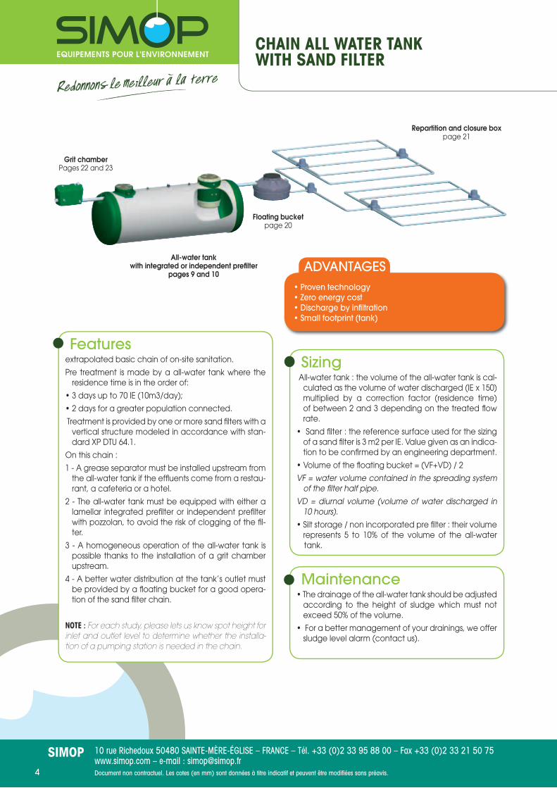
CHAIN ALL WATER TANKWITH SAND FILTER
• Proven technology• Zero energy cost• Discharge by infi ltration• Small footprint (tank)
ADVANTAGESAll-water tank
with integrated or independent prefi lterpages 9 and 10
Grit chamberPages 22 and 23
Floating bucketpage 20
Repartition and closure boxpage 21
Featuresextrapolated basic chain of on-site sanitation.
Pre treatment is made by a all-water tank where the residence time is in the order of:
• 3 days up to 70 IE (10m3/day);
• 2 days for a greater population connected.
Treatment is provided by one or more sand fi lters with a vertical structure modeled in accordance with stan-dard XP DTU 64.1.
On this chain :
1 - A grease separator must be installed upstream from the all-water tank if the effl uents come from a restau-rant, a cafeteria or a hotel.
2 - The all-water tank must be equipped with either a lamellar integrated prefi lter or independent prefi lter with pozzolan, to avoid the risk of clogging of the fi l-ter.
3 - A homogeneous operation of the all-water tank is possible thanks to the installation of a grit chamber upstream.
4 - A better water distribution at the tank’s outlet must be provided by a fl oating bucket for a good opera-tion of the sand fi lter chain.
NOTE : For each study, please lets us know spot height for inlet and outlet level to determine whether the installa-tion of a pumping station is needed in the chain.
Sizing All-water tank : the volume of the all-water tank is cal-
culated as the volume of water discharged (IE x 150) multiplied by a correction factor (residence time) of between 2 and 3 depending on the treated fl ow rate.
• Sand fi lter : the reference surface used for the sizing of a sand fi lter is 3 m2 per IE. Value given as an indica-tion to be confi rmed by an engineering department.
• Volume of the fl oating bucket = (VF+VD) / 2
VF = water volume contained in the spreading system of the fi lter half pipe.
VD = diurnal volume (volume of water discharged in 10 hours).
• Silt storage / non incorporated pre fi lter : their volume represents 5 to 10% of the volume of the all-water tank.
Maintenance• The drainage of the all-water tank should be adjusted
according to the height of sludge which must not exceed 50% of the volume.
• For a better management of your drainings, we offer sludge level alarm (contact us).

Document non contractuel. Les cotes (en mm) sont données à titre indicatif et peuvent être modifi ées sans préavis. 5
10 rue Richedoux 50480 SAINTE-MÈRE-ÉGLISE – FRANCE – Tél. +33 (0)2 33 95 88 00 – Fax +33 (0)2 33 21 50 75www.simop.com – e-mail : [email protected]
SIMOP
CHAIN DECANTER DIGESTERWITH SAND FILTER
• Proven technology• Zero energy cost• Discharge by infi ltration• Small footprint (tank)
ADVANTAGESdecanter digester
page 11
Grit chamberPages 22 and 23
Floating Bucketpage 20
Prefi lterpages 17, 18 and 19
Repartition and closure boxpage 21
FeaturesA decanter can be a pre treatment before further treatment or constitute a single treatment. The importance of this chain is directly related to the operation of the decanter digester. Indeed, the physi-cal separation of settling and digestion zones reduces sedimented sludge allowing to the decanter digester to be 2 to 3 times compacter than a all-water tank for the same treated fl ow.Treatment is provided by one or more sand fi lters with avertical structure modeled in accordance withstandard XP DTU 64.1
On this chain :1 - A grease separator must be installed upstream from the decanter digester if the effl uents come from a res-taurant, a cafeteria or a hotel.2 - The decanter digester must be equipped with an independent prefi lter with pozzolan to avoid the risk of clogging of the fi lter.3 - A homogeneous operation of the decanter digester is possible thanks to the installation of a grit chamber upstream.4 - A better water distribution at the outlet of the de-canter digester must be provided by a fl oating bucket for a good operation of the sand fi lter chain.
NOTE : For each study, please lets us know spot height for inlet and outlet level to determine whether the installa-tion of a pumping station is needed in the chain.
Sizing• Decanter digester (DD) : The volume is calculated as
the volume of water discharged (EH x 150) multiplied by a factor between 1.2 and 1.5 according to the sizing principles of water agencies.
• Sand fi lter : the reference surface used for the si-zing of a sand fi lter is 3 m2 per IE. Value given as an indication to be confi rmed by an engineering de-partment.
• Volume of the fl oating bucket = (VF+VD) / 2
VF = water volume contained in the spreading system of the fi lter half pipe.
VD = diurnal volume (volume of water discharged in 10 hours).
• Silt storage / non incorporated pre fi lter : for a quick sizing, their volume equal to 20% of the volume of the DD.
MaintenanceThe decanter digester must be drained once a year.

Document non contractuel. Les cotes (en mm) sont données à titre indicatif et peuvent être modifi ées sans préavis.6
10 rue Richedoux 50480 SAINTE-MÈRE-ÉGLISE – FRANCE – Tél. +33 (0)2 33 95 88 00 – Fax +33 (0)2 33 21 50 75www.simop.com – e-mail : [email protected]
SIMOP
ACTIVATED SLUDGE CHAINWITH DISCHARGE INTOSUPERFICIAL WATER ENVIRONMENT
• Small footprint• Absolute landscaping integration (100% buried)• No noise• Modular and expandable later• Proven technology of activated sludge• Perfect control of the sludge volumes to be drained
thanks to the primary decanter• Rejection quality in accordance with the Ministerial
Order of June 22, 2007• Easy maintenance thanks to a simple and robust
design designed for the user• Maintenance provided by licensed fi rmsthroughout France
Advantages
primary decanterpage 12Pumping station
optional
Grit chamberPages 22 and 23
OXYMOPpage 13
FeaturesThis chain is designed on the model of urban wastewa-ter treatment plants, and consists of :
• a primary settling (pre treatment)
• aeration / activation (treatment) (contact bacteria/water provided by diffusion through aero-ejector of fi ne air bubbles)
• a clarifi cation based on the lamellar settling (fi nishing),
• elimination of the excess sludge (storage in the di-gester).
It is characterized by a very low load operation where the volume of the aeration tank is the daily volume of effl uents (extended aeration principle).
Consisting of two tanks, this chain is suffi cient in itself.
Like any water treatment plant with activated sludge, this type of chain must operate with a supply of ef-fl uents as regular as possible (one-off variations accep-ted more or less 25% of the average load).
NOTE : For each study, please lets us know spot height for inlet and outlet level to determine whether the installa-tion of a pumping station is needed in the chain.
Maintenance • The primary clarifi er must be drained once a year.
• Oxymop must be drained once a year to 2/3 of its volume.
• Maintenance contract required for maintenance and adjustments of the electromechanical parts.
SizingPrimary decanter (Ref. : DP3/6321/...) : the volume of the primary clarifi er is the number of inhabitant equivalent multiplied by 150.
OXYMOP (Ref. : OXY3/6334...) : the volume of Oxymop is the number of inhabitant equivalent multiplied by 200 to 300.

Document non contractuel. Les cotes (en mm) sont données à titre indicatif et peuvent être modifi ées sans préavis. 7
10 rue Richedoux 50480 SAINTE-MÈRE-ÉGLISE – FRANCE – Tél. +33 (0)2 33 95 88 00 – Fax +33 (0)2 33 21 50 75www.simop.com – e-mail : [email protected]
SIMOP
• Small footprint• Rejection quality in accordance with the Ministerial
Order of June 22, 2007• Absolute landscaping integration• Supports load variations• Easy Maintenance• Proven technology of fi xed cultures• No noise
ADVANTAGES
Pumping stationoptional
Filtrapurpages 14 et 15
primary decanterpage 12
CHAIN FIXED CULTUREWITH DISCHARGE INTOSUPERFICIAL WATER ENVIRONMENT
MaintenanceFrom commissioning, a maintenance contract must be signed with a specialist certifi ed by the Simop company.
SizingThe sizing of the chain is made according to the population connected and rejection levels expected.
FeaturesThis chain is designed on the model of urban wastewa-ter treatment plants, and consists of :
• a primary settling (pre treatment)
• a bacterial massive (treatment) (contact bacteria/ water provided by spray on the bacterial support).
• clarifi cation based on a vertical settling.
Consisting of two or 3 tanks according to the models, this chain is suffi cient in itself.
NOTE : For each study, please lets us know spot height for inlet and outlet level to determine whether the installa-tion of a pumping station is needed in the chain.

Document non contractuel. Les cotes (en mm) sont données à titre indicatif et peuvent être modifi ées sans préavis.8
10 rue Richedoux 50480 SAINTE-MÈRE-ÉGLISE – FRANCE – Tél. +33 (0)2 33 95 88 00 – Fax +33 (0)2 33 21 50 75www.simop.com – e-mail : [email protected]
SIMOP
TREATMENT CHAINFOR GREY WATER
• Saving of 40 to 50% drinking water depending on the installation type• Discreet and easy Installation• Low power consumption• Do not generate residues•Easy maintenance
ADVANTAGESFeaturesThis treatment chain and reuse of grey water from showers consists of:
• a grey water reservoir ;
• a reservoir of treated and disinfected water ;
• a fi ltration unit ;
• a pressure equipment ;
• a UV disinfection equipment ;
• a chlorination equipment.
Treated water is reused mainly for watering gardens (excluding overhead) and for toilets.
Note : This type of chain requires the establishment of two networks of wastewater recovery (one for grey wa-ter and one for black water).
SizingAll parts of the chain is sized based on the volume of grey water which can be generated (showers, sinks,...).
Each sizing requires a special study.
Maintenance• Check the fl oat systems in the tanks
monthly
• Check the operation of the UV lamp
• Check the operation of the pumping systems
• Renew the fi lter material every year
Storage tanksfor greywater
GRISIMOPpage 16
Storage tanksfor treated water
Document non contractuel. Les cotes (en mm) sont données à titre indicatif et peuvent être modifi ées sans préavis. 9
10 rue Richedoux 50480 SAINTE-MÈRE-ÉGLISE – FRANCE – Tél. +33 (0)2 33 95 88 00 – Fax +33 (0)2 33 21 50 75www.simop.com – e-mail : [email protected]
SIMOP
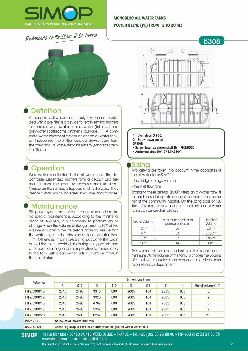
1 - Vent pipes Ø 100.2 - Screw-dawn coversOPTION• Screw-dawn extension shaft Ref. RH2/6030.• Anchoring strap Ref. CA3/FX24/01.
MONOBLOC ALL WATER TANKS
POLYETHYLENE (PE) FROM 12 TO 20 M3
6308
Defi nitionA monobloc all-water tank in polyethylene not equip-ped with a pre fi lter is a device to retain settling matters in domestic wastewater : blackwater (toilets,...) and greywater (bathrooms, kitchens, laundries,...). A com-plete water treatment system incldes an all-water tank, an independent pre fi lter located downstream from the tank and a waste disposal system (sand fi lter, zeo-lite fi lter,...)
Operation Wastewater is collected in the all-water tank. The de-cantable suspended matters form a deposit and fer-ment. Their volume gradually decreases and is stabilized. Grease on the surface is trapped and hydrolyzed. They create a «hat» which increases in volume and stabilizes.
MaintainancePits polyethylene are resistant to corrosion and require no special maintenance. According to the ministerial order of 07/09/09, it is necessary to perform an oil change when the volume of sludge reaches 50% of the volume of water in the pit. Before draining, ensure that the water level in the piezometer is not greater than 1 m. Otherwise, it is necessary to postpone the drain or fold the cloth. Avoid drain during rainy periods and after each draining, and it is imperative to immediately fi ll the tank with clean water until it overfl ows through the outlet pipe.
SizingTwo criteria are taken into account in the capacities of the all-water tanks SIMOP :
- The sludge storage volume
- The inlet fl ow rate
Thanks to these criteria, SIMOP offers an all-water tank fi t for each case taking into account the permanent use or not of the community habitat. On the sizing basis of 150 liters of water per day and per inhabitant, our all-water tanks can be used as follows :
Useful Volume Maximum number of permanent users
Prefi lter Volume
12 m3 26 0.6 m3
15 m3 33 0.75 m3
17 m3 37 0.85 m3
20 m3 44 1 m3
The volume of the independent pre fi lter should equal minimum 5% the volume of the tank. To choose the volume of the all-water tank for a non-permanent use, please refer to our research department.
ReferenceDimensions in mm
A Ø B C Ø D E Ø F G H Useful Volume (m3)
FTE2/6308/10 2840 2490 3378 600 2085 160 2035 805 10
FTE2/6308/12 2840 2490 3928 600 2085 160 2035 805 12
FTE2/6308/15 2840 2490 4782 600 2085 160 2035 805 15
FTE2/6308/17 2840 2490 5332 600 2085 160 2035 805 17
FTE2/6308/20 2840 2490 6232 600 2085 160 2035 805 20
RH2/6030 Screw-dawn covers 300 mm
CA3/FX24/01 Anchoring strap to click for an installation on ground with a water table
B
A A
1 1
C
Document non contractuel. Les cotes (en mm) sont données à titre indicatif et peuvent être modifi ées sans préavis.10
10 rue Richedoux 50480 SAINTE-MÈRE-ÉGLISE – FRANCE – Tél. +33 (0)2 33 95 88 00 – Fax +33 (0)2 33 21 50 75www.simop.com – e-mail : [email protected]
SIMOP
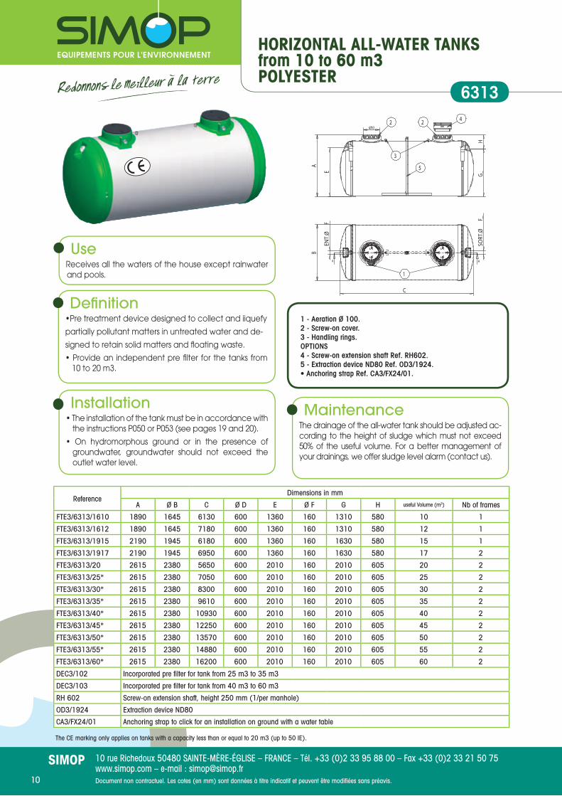
HORIZONTAL ALL-WATER TANKSfrom 10 to 60 m3POLYESTER
6313
The CE marking only applies on tanks with a capacity less than or equal to 20 m3 (up to 50 IE).
ReferenceDimensions in mm
A Ø B C Ø D E Ø F G H useful Volume (m3) Nb of frames
FTE3/6313/1610 1890 1645 6130 600 1360 160 1310 580 10 1
FTE3/6313/1612 1890 1645 7180 600 1360 160 1310 580 12 1
FTE3/6313/1915 2190 1945 6180 600 1360 160 1630 580 15 1
FTE3/6313/1917 2190 1945 6950 600 1360 160 1630 580 17 2
FTE3/6313/20 2615 2380 5650 600 2010 160 2010 605 20 2
FTE3/6313/25* 2615 2380 7050 600 2010 160 2010 605 25 2
FTE3/6313/30* 2615 2380 8300 600 2010 160 2010 605 30 2
FTE3/6313/35* 2615 2380 9610 600 2010 160 2010 605 35 2
FTE3/6313/40* 2615 2380 10930 600 2010 160 2010 605 40 2
FTE3/6313/45* 2615 2380 12250 600 2010 160 2010 605 45 2
FTE3/6313/50* 2615 2380 13570 600 2010 160 2010 605 50 2
FTE3/6313/55* 2615 2380 14880 600 2010 160 2010 605 55 2
FTE3/6313/60* 2615 2380 16200 600 2010 160 2010 605 60 2
DEC3/102 Incorporated pre fi lter for tank from 25 m3 to 35 m3
DEC3/103 Incorporated pre fi lter for tank from 40 m3 to 60 m3
RH 602 Screw-on extension shaft, height 250 mm (1/per manhole)
OD3/1924 Extraction device ND80
CA3/FX24/01 Anchoring strap to click for an installation on ground with a water table
UseReceives all the waters of the house except rainwater and pools.
Defi nition•Pre treatment device designed to collect and iiquefy
partially pollutant matters in untreated water and de-
signed to retain solid matters and fl oating waste.
• Provide an independent pre fi lter for the tanks from 10 to 20 m3.
Installation• The installation of the tank must be in accordance with
the instructions P050 or P053 (see pages 19 and 20).
• On hydromorphous ground or in the presence of groundwater, groundwater should not exceed the outlet water level.
MaintenanceThe drainage of the all-water tank should be adjusted ac-cording to the height of sludge which must not exceed 50% of the useful volume. For a better management of your drainings, we offer sludge level alarm (contact us).
1 - Aeration Ø 100.2 - Screw-on cover.3 - Handling rings.OPTIONS4 - Screw-on extension shaft Ref. RH602.5 - Extraction device ND80 Ref. OD3/1924.• Anchoring strap Ref. CA3/FX24/01.
Document non contractuel. Les cotes (en mm) sont données à titre indicatif et peuvent être modifi ées sans préavis. 11
10 rue Richedoux 50480 SAINTE-MÈRE-ÉGLISE – FRANCE – Tél. +33 (0)2 33 95 88 00 – Fax +33 (0)2 33 21 50 75www.simop.com – e-mail : [email protected]
SIMOP
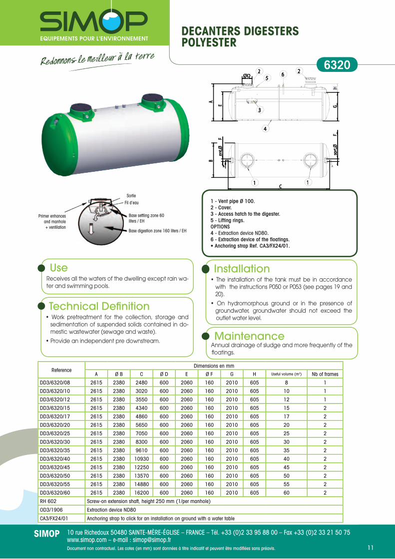
DECANTERS DIGESTERSPOLYESTER
6320
Primer enhancesand manhole+ ventilation
Base digestion zone 160 liters / EH
Base settling zone 60 liters / EH
Fil d’eauSortie
Technical Defi nition• Work pretreatment for the collection, storage and
sedimentation of suspended solids contained in do-mestic wastewater (sewage and waste).
• Provide an independent pre downstream.
Use Receives all the waters of the dwelling except rain wa-ter and swimming pools.
Installation• The installation of the tank must be in accordance
with the instructions P050 or P053 (see pages 19 and 20).
• On hydromorphous ground or in the presence of groundwater, groundwater should not exceed the outlet water level.
1 - Vent pipe Ø 100.2 - Cover.3 - Access hatch to the digester.5 - Lifting rings.OPTIONS4 - Extraction device ND80.6 - Extraction device of the fl oatings.• Anchoring strap Ref. CA3/FX24/01.
MaintenanceAnnual drainage of sludge and more frequently of the fl oatings.
ReferenceDimensions en mm
A Ø B C Ø D E Ø F G H Useful volume (m3) Nb of frames
DD3/6320/08 2615 2380 2480 600 2060 160 2010 605 8 1
DD3/6320/10 2615 2380 3020 600 2060 160 2010 605 10 1
DD3/6320/12 2615 2380 3550 600 2060 160 2010 605 12 1
DD3/6320/15 2615 2380 4340 600 2060 160 2010 605 15 2
DD3/6320/17 2615 2380 4860 600 2060 160 2010 605 17 2
DD3/6320/20 2615 2380 5650 600 2060 160 2010 605 20 2
DD3/6320/25 2615 2380 7050 600 2060 160 2010 605 25 2
DD3/6320/30 2615 2380 8300 600 2060 160 2010 605 30 2
DD3/6320/35 2615 2380 9610 600 2060 160 2010 605 35 2
DD3/6320/40 2615 2380 10930 600 2060 160 2010 605 40 2
DD3/6320/45 2615 2380 12250 600 2060 160 2010 605 45 2
DD3/6320/50 2615 2380 13570 600 2060 160 2010 605 50 2
DD3/6320/55 2615 2380 14880 600 2060 160 2010 605 55 2
DD3/6320/60 2615 2380 16200 600 2060 160 2010 605 60 2
RH 602 Screw-on extension shaft, height 250 mm (1/per manhole)
OD3/1906 Extraction device ND80
CA3/FX24/01 Anchoring strap to click for an installation on ground with a water table

Document non contractuel. Les cotes (en mm) sont données à titre indicatif et peuvent être modifi ées sans préavis.12
10 rue Richedoux 50480 SAINTE-MÈRE-ÉGLISE – FRANCE – Tél. +33 (0)2 33 95 88 00 – Fax +33 (0)2 33 21 50 75www.simop.com – e-mail : [email protected]
SIMOP
PRIMARY DECANTERS 8 to 30 m3FOR OXYMOPPOLYESTER
Extension shaft coverand manhole
+ aerationdigestion zone 160 liter/EH base
clarifi cation zone60 liter/IE base
Outlet
UseDesigned for the collect, the sedimentation and the storage of the suspended solids (TSS) contained in do-mestic wastewater (soils water and household waste water).
Defi nitionUpstream from an OXYMOP, the decanter is composed by
two different compartments : • A lengthwise clarifi cation compartment enables the
gravitational sedimentation of the suspended solids. The decanted suspended solids enter the inferior compartment thanks to some holes located in the decanter basis.
• Access to a digester compartment where sludge collected are stored and are compacted. Their digestion is realized in the non-aerated zone (anaerobic).
Installation• The installation of the tank must be in accordance
with the instructions P050 or P053 (see pages 19 and 20).
• On hydromorphous ground or in the presence of groundwater, groundwater should not exceed the outlet water level.
Maintenance• Biannual drainage of sludge and more frequently
of the fl oatings. A trap located in the clarifi cation compartment leaves access to the digester compartment.
ReferenceDimensions in mm
A Ø B C Ø D E Ø F G H Volume use(m3) Nb frames
DP3/6321/08 2615 2380 2480 600 2110 160 2060 555 08 1
DP3/6321/12 2615 2380 3550 600 2110 160 2060 555 12 1
DP3/6321/17 2615 2380 4860 600 2110 160 2060 555 17 2
DP3/6321/20 2615 2380 5650 600 2110 160 2060 555 20 2
DP3/6321/25 2615 2380 7050 600 2110 160 2060 555 25 2
DP3/6321/30 2615 2380 8300 600 2110 160 2060 555 30 2
RH602 Screw-on extension shaft, 250 mm
CA3/FX24/01 Anchoring strap to click for an installation on ground with a water table
1 - Aeration Ø 100.2 - Screw-on covers.3 - Access hatch to the digester.4 - Extraction device ND80 with symmetric conection.5 - Lifting ring.OPTION• Screw-on extension shaft Ref. RH602.• Anchoring strap Ref. CA3/FX24/01.
6321
Inlet level

Document non contractuel. Les cotes (en mm) sont données à titre indicatif et peuvent être modifi ées sans préavis. 13
10 rue Richedoux 50480 SAINTE-MÈRE-ÉGLISE – FRANCE – Tél. +33 (0)2 33 95 88 00 – Fax +33 (0)2 33 21 50 75www.simop.com – e-mail : [email protected]
SIMOP
OXYMOP 50-400 IEPOLYESTER
6334
Reference
Dimensions in mm
IE *mini/maxi A Ø B C Ø D E Ø F G H Useful
Volume (m3)Nb
FramesWeight
kgPrimary
decanter in m3
OXY3/6334/20 50/80 2615 2380 5650 600 2060 160 2010 605 20 2 1600 12
OXY3/6334/25 81/110 2615 2380 7050 600 2060 160 2010 605 25 2 1900 17
OXY3/6334/30 111/140 2615 2380 8300 600 2060 160 2010 605 30 2 2200 20
OXY3/6334/35 141/175 2615 2380 9610 600 2060 160 2010 605 35 2 2500 25
OXY3/6334/40 176/200 2615 2380 10930 600 2060 160 2010 605 40 2 2800 30
RH602 Screw-on extension shaft, 250 mm
CA3/FX24/01 Anchoring strap to click for an installation on ground with a water table
UseTreatment of domestic waste from 51 to 200 users.
Technical Defi nition• Water treatment plants with activated sludge deve-loped in GRP tanks. They are composed by an aeration basin followed by a clarifi er.• A primary clarifi er is needed upstream, see technical sheet 6321.
NOTE : Each project is subject to a specifi c study. For this, it is indispensable to know spot height for inlet and outlet level of the chain.
Installation• The installation of the tank must be in accordance with
the instructions P050 or P053 (see pages 19 and 20).• On hydromorphous ground or in the presence of
groundwater, groundwater should not exceed the outlet water level
• Inoculate with biomass.• A company authorized by SIMOP makes connec-
tions, testing and commissioning.
Maintenance• Drainage of the primary clarifi er once a year.• Drainage of the Oxymop once a year to 2/3 of its
volume.• Maintenance contract required for maintenance
and adjustments of the electromechanics
1 - Aeration.2 - Aerator.3 - Sludge recirculation pump.4 - Sludge disposal pump.5 - lamellar decanter.6 - Standard electrical box.OPTIONS• Screw-on extension shaft Ref. RH602.• Anchoring strap Ref. CA3/FX24/01.
5
* Beyond 200 EH module, same combination of OXY3/6934 to achieve the desired capacity.

Document non contractuel. Les cotes (en mm) sont données à titre indicatif et peuvent être modifi ées sans préavis.14
10 rue Richedoux 50480 SAINTE-MÈRE-ÉGLISE – FRANCE – Tél. +33 (0)2 33 95 88 00 – Fax +33 (0)2 33 21 50 75www.simop.com – e-mail : [email protected]
SIMOP
COMPACT and BIOLOGICALWATER-TREATMENT PLANT FILTRAPURCAPACITY FROM 50 TO 300 IE AND MORE
6344
Type FC2N to FC6N- Monobloc- With clarifi er / digester integrated- Up to 50 Inhabitant Equivalents
UseWater treatment plants FILTRAPUR® are designed to
clean wastewater from tourist areas (hotels, camp-sites, holiday resorts...) of variable population or not and generally any group of isolated houses.
Depending on the sizing, it can provide up to 95% re-moval of organic carbon matter and meet nitrifac-tion. Very compact units FILTRAPUR ® can be easily integrated into the environment and have no odor nuisance.
Note :• Models FC2N to FC6N do not require settling/diges-
tion tanks contrary to the models FC7N to FC23N.• Units FC20N to FC23N are double sets.• The models can be adapted to the demand for
higher discharge requirements.
Operation• Waste water is introduced into the primary clarifi ca-
tion compartment (1) where solid matter are remo-ved by gravity. Clarifi ed water is then blended with recycled water by passage through a second com-partment (2) and then pumped (4) on the biological unit.
• Pumped water is distributed on the fi lter material by regular spraying (5) then percolates through it to be purifi ed by micro-organisms which grow in the bac-terial fi lter. (3) A part of the purifi ed water is returned to the pumping compartment (2) to ensure a perma-nent recirculation on the bacteria fi lter.
• The other part undergoes a fi nal settling in the cla-rifi cation compartment (6). The latest settleable so-lids are eliminated before discharge of the treated water. At regular intervals, a recirculation pump (7) returns the treated effl uent into the primary clarifi ca-tion compartment placed at the top. This ensures a regular load on the purifi cation unit.
• Models FILTRAPUR ® FC2N FC6N to have an integra-ted primary clarifi cation chamber, which simplifi es the installation of the unit. For larger sizes, FC7N to FC23N, it is necessary to provide a clarifi cation/diges-tion device before the biological plant.
Model ofFILTRAPUR®
Reinforced Treatment
Standard Treatment
Rejection Level(25/30/15)*
Rejection Level(25/30/50)*
Inhabitant equivalents connected
FC7 52 65
FC9 68 85
FC10 88 110
FC11 104 130
FC12 120 150
FC20 136 170
FC21 176 220
FC22 208 260
FC23 240 300
Selection Table
* : (BOD5, SS, TKN in mgl).
16
7
2
3
4
5

Document non contractuel. Les cotes (en mm) sont données à titre indicatif et peuvent être modifi ées sans préavis. 15
10 rue Richedoux 50480 SAINTE-MÈRE-ÉGLISE – FRANCE – Tél. +33 (0)2 33 95 88 00 – Fax +33 (0)2 33 21 50 75www.simop.com – e-mail : [email protected]
SIMOP
COMPACT and BIOLOGICALWATER-TREATMENT PLANT FILTRAPURCAPACITY FROM 50 TO 300 IE AND MORE
6344
FC7N to FC23N type- With clarifi er / digester at the head- From 65 to 300 Inhabitant Equivalents
InstallationQuick and easy installation :1 - Installation of the lower compartment on a concrete
bed.2 - Install on a level and calibrate.3 - Ballasting by fi lling with water before sealing or in-
fi lling.4 - Installing the biological fl oor.
1 6
7
2
3
4
5

Document non contractuel. Les cotes (en mm) sont données à titre indicatif et peuvent être modifi ées sans préavis.16
10 rue Richedoux 50480 SAINTE-MÈRE-ÉGLISE – FRANCE – Tél. +33 (0)2 33 95 88 00 – Fax +33 (0)2 33 21 50 75www.simop.com – e-mail : [email protected]
SIMOP
GRISIMOPGREY WATER TREATMENT
Defi nitionGRISIMOP is a treatment plant reusing greywater from showers and sinks. After fi ltration and disinfection, greywater is reused mainly for watering gardens (excluding spray irrigation) and for toilets. This greywater treatment system has been designed for domestic and industrial applications.
Applications :• Housing - apartments, buildings...• Tourism - camp sites, hotels...• Leasure - sports halls, swimming pools... This greywater reuse system saves 40% of the consumption of drinking water. In some types of applications, we can even reduce water consumption by 50%.
The GRISIMOP consists of :• a tank for greywater coming from showers, sinks (not included and to be determined according to the context) ;• a greywater tank fi ltered and disinfected (not included to be determined according to the context) ;• a fi ltration unit ;• a pumping unit ;• UV disinfection equipment ;• chlorination equipment .
OperationThe design of water storage tanks is carried from the volume of greywa-ter which can be generated (shower, sinks,...) or according to treated water needs depending onapplications.
Greywater is stored in a fi rst tank, they are then sent to the fi lter device via the pump «fi ltration».
The fi ltration device consists of a sand fi lter of small particle size so as to retain suspended solids in water. This fi lter is automatically washed with treated water every 7 days when the pressure becomes too important (clogging). The maximum pressure fi ltration is 2.5 Kg/cm2 (35.5 PSI).
Then, the fi ltered water passes through the UV device which destroys pathogenic micro-organisms by oxidizing them. The UV lamp has a ser-vice life of 8000 hours (12 months).
Once the UV lamp stops functioning, the fi ltration system is locked to prevent any contamination. In this case the connection to the drinking water system is automatically performed.
Once fi ltered and disinfected, water is stored in a second reservoir.
The system fi lters and disinfects the water accumulated in the tank se-veral times a day as needed.
Then, the treated water is sent to the network by an impulse pump when a pressure drop is observed. Water tanks have an overfl ow sys-tem in case of overfi lling
MaintenanceMaintenance as well as system maintenance depends mainly on
the nature of greywater and the destination of the treated water. The maintenance of this system is easy and requires no special qualifi cations. The main interventions of maintenance are :
• Check the operation of the fl oat in the treated water reservoir every month
• Check the operation of the UV lamp and change it if necessary.• Check the operation of the different pumping systems.• Renovate the fi ltering material every year.
• This greywater recovery system saves from 40% to 50% drinking water (depending on the installation type).• Easy and discreet installation.• Low power consumption.• Quick amortization.• Do not generate waste.• Easy maintenance...
ADVANTAGES
6070
Option : DOSCOL, coloring jigger
Références GR6070/02 GR6070/06 GR6070/10
Maximum treated volume (m3/day) 48 144 240
Dimensions of the compact equipment (mm)
Length 700 700 700
Height 1250 1250 1250
Width 680 600 600
Dimensions of the fi ltration equipment (mm)
Diameter Included in the compact equipment 500 900
Height 700 1145

Document non contractuel. Les cotes (en mm) sont données à titre indicatif et peuvent être modifi ées sans préavis. 17
10 rue Richedoux 50480 SAINTE-MÈRE-ÉGLISE – FRANCE – Tél. +33 (0)2 33 95 88 00 – Fax +33 (0)2 33 21 50 75www.simop.com – e-mail : [email protected]
SIMOP
PRE-FILTERSPOLYETHYLENE
6365
UseTo retain suspended solids.
Defi nition• The polyethylene pre-fi lter is used for retaining
suspended solids. • It is placed downstream of a liquefi er (all-water tank,
decanter digester) upstream of an underground spreading system or drained fi lter bed.
Installation• The device will be buried outside a building and must be
installed on a perfect level. It must be buried outside of a place of passing vehicles.
• The cover must reach the natural ground level and will always remain accessible for maintenance. The bottom of the hole must be perfectly fl at and covered with 10 cm of sand. Backfi ll with sand, never stone or gravel.
• The device is fi lled with pozzolan or other fi lter material with a regular granulation between 40 and 50 mm. This is done before or at the same time as the infi lling.
• If the cover can not reach the ground level, a concrete slab must be poured resting on stable ground in order to withstand the strains imposed.
Maintenance The device made of PE is corrosion resistant and re-
quires no maintenance.• Check monthly the fi lter materials. Aspirate the super-
natant at least once a year.• On average, the fi lter material is changed every 2
years.
Reference
Dimensions in mm
A Ø B C Ø D E Ø F G H useful volume (litrers)
pozzolanRef. PZ01 (Nb of bags)
DEC2/0801 1130 1119 1694 400 760 160 740 390 800 13
DEC2/1001 1350 1160 – 500 1090 160 1070 280 1000 16
DEC2/2001 1500 1550 – 500 1240 160 1190 310 2000 33
DEC2/3001 1500 1930 – 500 1250 160 1200 300 3000 50
DEC2/4001 1840 1930 – 500 1590 160 1540 300 4000 66
DEC2/5001 1840 2400 – 500 1480 160 1430 410 5000 83
DEC2/6001 2010 2400 – 500 1660 160 1610 400 6000 100
RH 2601 Extension shaft to be laid down for DEC2/0801
RH 500 Extension shaft to be laid down
1 - Screw-on coverOPTION2 - Pozzolan.
Document non contractuel. Les cotes (en mm) sont données à titre indicatif et peuvent être modifi ées sans préavis.18
10 rue Richedoux 50480 SAINTE-MÈRE-ÉGLISE – FRANCE – Tél. +33 (0)2 33 95 88 00 – Fax +33 (0)2 33 21 50 75www.simop.com – e-mail : [email protected]
SIMOP
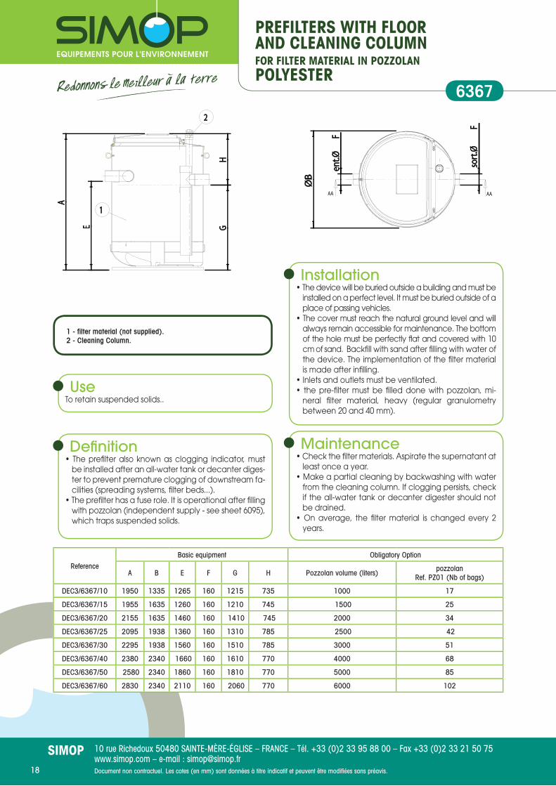
PREFILTERS WITH FLOORAND CLEANING COLUMNFOR FILTER MATERIAL IN POZZOLANPOLYESTER
63672
1
E
A
GH
ØB
ent.Ø
F
sort
.ØF
AA AA
2
1
E
A
GH
ØB
ent.Ø
F
sort
.ØF
AA AA
UseTo retain suspended solids..
Defi nition• The prefi lter also known as clogging indicator, must
be installed after an all-water tank or decanter diges-ter to prevent premature clogging of downstream fa-cilities (spreading systems, fi lter beds...).
• The prefi lter has a fuse role. It is operational after fi lling with pozzolan (independent supply - see sheet 6095), which traps suspended solids.
Installation• The device will be buried outside a building and must be
installed on a perfect level. It must be buried outside of a place of passing vehicles.
• The cover must reach the natural ground level and will always remain accessible for maintenance. The bottom of the hole must be perfectly fl at and covered with 10 cm of sand. Backfi ll with sand after fi lling with water of the device. The implementation of the fi lter material is made after infi lling.
• Inlets and outlets must be ventilated.• the pre-fi lter must be fi lled done with pozzolan, mi-
neral fi lter material, heavy (regular granulometry between 20 and 40 mm).
Maintenance• Check the fi lter materials. Aspirate the supernatant at
least once a year.• Make a partial cleaning by backwashing with water
from the cleaning column. If clogging persists, check if the all-water tank or decanter digester should not be drained.
• On average, the fi lter material is changed every 2 years.
1 - fi lter material (not supplied).2 - Cleaning Column.
ReferenceBasic equipment Obligatory Option
A B E F G H Pozzolan volume (liters) pozzolanRef. PZ01 (Nb of bags)
DEC3/6367/10 1950 1335 1265 160 1215 735 1000 17
DEC3/6367/15 1955 1635 1260 160 1210 745 1500 25
DEC3/6367/20 2155 1635 1460 160 1410 745 2000 34
DEC3/6367/25 2095 1938 1360 160 1310 785 2500 42
DEC3/6367/30 2295 1938 1560 160 1510 785 3000 51
DEC3/6367/40 2380 2340 1660 160 1610 770 4000 68
DEC3/6367/50 2580 2340 1860 160 1810 770 5000 85
DEC3/6367/60 2830 2340 2110 160 2060 770 6000 102

Document non contractuel. Les cotes (en mm) sont données à titre indicatif et peuvent être modifi ées sans préavis. 19
10 rue Richedoux 50480 SAINTE-MÈRE-ÉGLISE – FRANCE – Tél. +33 (0)2 33 95 88 00 – Fax +33 (0)2 33 21 50 75www.simop.com – e-mail : [email protected]
SIMOP
PREFILTERS WITH FLOORFOR FILTER MATERIAL IN ROTPROOF HDPE CELLSPOLYESTER
6368
2
1
E
A
GH
ØB
ent.Ø
F
sort
.ØF
AA AA
ReferenceDimensions in mm
A Ø B E Ø F G H Material volume (liters)
DEC3/6368/10 1950 1335 1265 160 1215 735 1000
DEC3/6368/15 1955 1635 1260 160 1210 745 1500
DEC3/6368/20 2155 1635 1460 160 1410 745 2000
DEC3/6368/25 2095 1938 1360 160 1310 785 2500
DEC3/6368/30 2295 1938 1560 160 1510 785 3000
DEC3/6368/40 2380 2340 1660 160 1610 770 4000
DEC3/6368/50 2580 2340 1860 160 1810 770 5000
DEC3/6368/60 2830 2340 2110 160 2110 770 6000
KREL4-089-017 Support 150 kg
KREL4-089-15 Bracket 150 kg
USETo retain suspended solids.
Technical Defi nition• The prefi lter also known as clogging indicator, must
be installed after an all-water tank or decanter diges-ter to prevent premature clogging of downstream fa-cilities (spreading systems, fi lter beds...).
• The prefi lter has a fuse role. It is delivered with the fi lter material. Suspended solids are trapped by the fi lter material contained in the prefi lter.
• Cells ETC 200 in HDPE, synthetic, rotproof and stable material, have comparable effi cacy to pozzolan for a lower weight (300 m²/m3 specifi c surface, porosity of 90%, density 70 kg/m3). These spheres are delive-red inside a string bag of a net volume of about 500 liters, a weight of 35 kg. Greater ease in handling du-ring maintenance operations because they require no hoist.
Installation• The device will be buried outside a building and must be
installed on a perfect level. It must be buried outside of a place of passing vehicles.
• The cover must reach the natural ground level and will always remain accessible for maintenance. The bottom of the hole must be perfectly fl at and covered with 10 cm of sand. Backfi ll using sand or gravel. Fill the device with clean water up before carry out lateral backfi ll.
• Inlets and outlets must be ventilated.
Maintenance• Aspirate the supernatant at least once a year.• Remove the string bags then wash to the water jet
and replace them after drainage of the prefi lter.• If the option «cleaning column» was ordered, the fi lter
material can be cleaned by backwashing with clean water.
1 - Filter material. Ref. ETC200.OPTIONS2 - Cleaning column from 1000 to 4000 L, Ref. KOD3/DEC10A40 and 5000-6000 L, Ref. KOD3/DEC50A60.• Support. No. KREL4-089-017.• Bracket 150 kg. Ref. KREL4-089-15.
Document non contractuel. Les cotes (en mm) sont données à titre indicatif et peuvent être modifi ées sans préavis.20
10 rue Richedoux 50480 SAINTE-MÈRE-ÉGLISE – FRANCE – Tél. +33 (0)2 33 95 88 00 – Fax +33 (0)2 33 21 50 75www.simop.com – e-mail : [email protected]
SIMOP
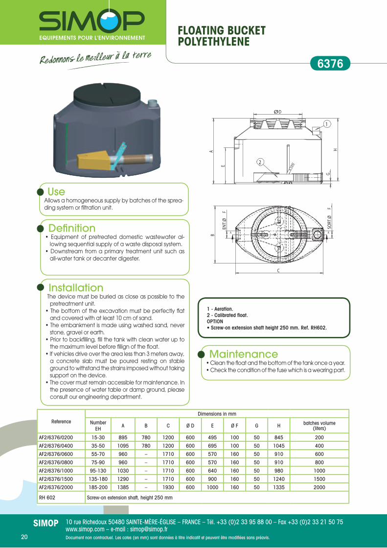
FLOATING BUCKETPOLYETHYLENE
6376
Installation The device must be buried as close as possible to the
pretreatment unit.• The bottom of the excavation must be perfectly fl at
and covered with at least 10 cm of sand.• The embankment is made using washed sand, never
stone, gravel or earth.• Prior to backfi lling, fi ll the tank with clean water up to
the maximum level before fi llign of the fl oat.• If vehicles drive over the area less than 3 meters away,
a concrete slab must be poured resting on stable ground to withstand the strains imposed without taking support on the device.
• The cover must remain accessible for maintenance. In the presence of water table or damp ground, please consult our engineering department.
Maintenance• Clean the fl oat and the bottom of the tank once a year.• Check the condition of the fuse which is a wearing part.
UseAllows a homogeneous supply by batches of the sprea-ding system or fi ltration unit.
Defi nition• Equipment of pretreated domestic wastewater al-
lowing sequential supply of a waste disposal system.• Downstream from a primary treatment unit such as
all-water tank or decanter digester.
ReferenceDimensions in mm
Number EH A B C Ø D E Ø F G H batches volume
(liters)
AF2/6376/0200 15-30 895 780 1200 600 495 100 50 845 200
AF2/6376/0400 35-50 1095 780 1200 600 695 100 50 1045 400
AF2/6376/0600 55-70 960 – 1710 600 570 160 50 910 600
AF2/6376/0800 75-90 960 – 1710 600 570 160 50 910 800
AF2/6376/1000 95-130 1030 – 1710 600 640 160 50 980 1000
AF2/6376/1500 135-180 1290 – 1710 600 900 160 50 1240 1500
AF2/6376/2000 185-200 1385 – 1930 600 1000 160 50 1335 2000
RH 602 Screw-on extension shaft, height 250 mm
1 - Aeration.2 - Calibrated fl oat.OPTION• Screw-on extension shaft height 250 mm. Ref. RH602.

Document non contractuel. Les cotes (en mm) sont données à titre indicatif et peuvent être modifi ées sans préavis. 21
10 rue Richedoux 50480 SAINTE-MÈRE-ÉGLISE – FRANCE – Tél. +33 (0)2 33 95 88 00 – Fax +33 (0)2 33 21 50 75www.simop.com – e-mail : [email protected]
SIMOP
CONNECTING BOXESPOLYETHYLENE
6060
Extension shaftRH2/03/15
Repartition and closure boxREP2/04/04
EFFLUENT DISTRIBUTORPOLYETHYLENE
6369
UseDownstream or upstream from the fi lter.
Defi nition• Used for a better transit of the effl uent in accordance
with standard XP DTU 64.1.• Facilitates the maintenance of the pipes and effl uent
samples.• Impermeable to parasite water • Insensitive to H2S.
UseEnsures an equal distribution of effl uent.
Defi nitionAn effl uent distributor is a device used for ensuring an equal distribution of the effl uents in the spreading systems or before tanks or decanters laid in parallel.
Installation• Meet requirements of the standard XP DTU 64.1.• For the installation of distributors (excavation and
installation), the main points to observe are :- The realization of a bed of 0.10 m thick.- The fl atness of the manhole after installation.- The surface fi lling with sand.- Accessibility and visibility of manholes.
Maintenance• Periodically clean the unit with water.• Reminder : the device is delivered with a shutter
which will be used to lock an outlet to make easier self-cleaning or maintenance.
Reference Dimensions in mm
A B C E Ø F G
REP2/04/04 420 306 400 50 100 10REC2/02/13 1300 306 400 10 100 10RH2/03/15 Screw-on extension shafts in polypropylene Ø 306 - useful height150 mm
RH2/02/30 Screw-on extension shafts in polypropylene Ø 306 - useful height 300 mm
ReferenceDimensions in mm
A Ø B Ø D E Ø F G Ø H
REP2/500 580 790 630 300 160 60 100
RH2301 250 790 630
Collecting boxREC2/02/13
ø
SORT. Ø F SORT. Ø H
E
A
øB
G
C
øFøF
150
ø 306

Document non contractuel. Les cotes (en mm) sont données à titre indicatif et peuvent être modifi ées sans préavis.22
10 rue Richedoux 50480 SAINTE-MÈRE-ÉGLISE – FRANCE – Tél. +33 (0)2 33 95 88 00 – Fax +33 (0)2 33 21 50 75www.simop.com – e-mail : [email protected]
SIMOP
GRIT CHAMBERSPOLYETHYLENE
6360
UseProtects a waste water treatment plant by collecting the objects larger than 50 mm.
Defi nitionA grit chamber is used to separate and discharge bulky materials in the effl uent which may affect the operation of the installation. We offer DG2 with a high density polyethylene tank equipped with a rake basket (galvanized round bar). The spacing between the bars is 50 mm.
Installation The device will be installed outside a building and will
be laid perfectly level.• It will be buried in a zone protected from vehicles
passing. The cover should be level with the fi nished ground and remain accessible for maintenance. The bottom of the excavation must be covered with 10 cm of sand. The embankment is made using sand, ne-ver stone or gravel
• Using extension shafts is not recommended foreasy handling of the basket.
Maintenance• Eliminate all matter refused by screening which will
be removed with household waste.• Rinse the device with clean water.
ReferenceDimensions in mm
A B Ø D E Ø F G H Total volume (liters)
DG2/6360/02 500 790 740 300 160 20 480 200
Document non contractuel. Les cotes (en mm) sont données à titre indicatif et peuvent être modifi ées sans préavis. 23
10 rue Richedoux 50480 SAINTE-MÈRE-ÉGLISE – FRANCE – Tél. +33 (0)2 33 95 88 00 – Fax +33 (0)2 33 21 50 75www.simop.com – e-mail : [email protected]
SIMOP
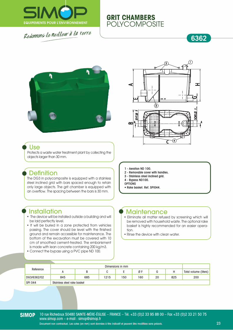
GRIT CHAMBERSPOLYCOMPOSITE
6362
UseProtects a waste water treatment plant by collecting the objects larger than 30 mm.
Defi nitionThe DG3 in polycomposite is equipped with a stainless steel inclined grid with bars spaced enough to retain only large objects. The grit chamber is equipped with an overfl ow. The spacing between the bars is 30 mm.
Installation• The device will be installed outside a building and will
be laid perfectly level.• It will be buried in a zone protected from vehicles
passing. The cover should be level with the fi nished ground and remain accessible for maintenance. The bottom of the excavation must be covered with 10 cm of smoothed cement-treated. The embankment is made with lean concrete containing 200 kg/m3.
• Connect the bypass using a PVC pipe ND 100.
Maintenance• Eliminate all matter refused by screening which will
be removed with household waste. The optional rake basket is highly recommended for an easier opera-tion.
• Rinse the device with clean water.
ReferenceDimensions in mm
A B C E Ø F G H Total volume (liters)
DG3/6362/02 845 685 1215 150 160 20 825 200
SPI 044 Stainless steel rake basket
1 - Aeration ND 100.2 - Removable cover with handles.3 - Stainless steel inclined grid.4 - Bypass ND100.OPTIONS• Rake basket. Ref. SPI044.
Document non contractuel. Les cotes (en mm) sont données à titre indicatif et peuvent être modifi ées sans préavis.24
10 rue Richedoux 50480 SAINTE-MÈRE-ÉGLISE – FRANCE – Tél. +33 (0)2 33 95 88 00 – Fax +33 (0)2 33 21 50 75www.simop.com – e-mail : [email protected]
SIMOP24
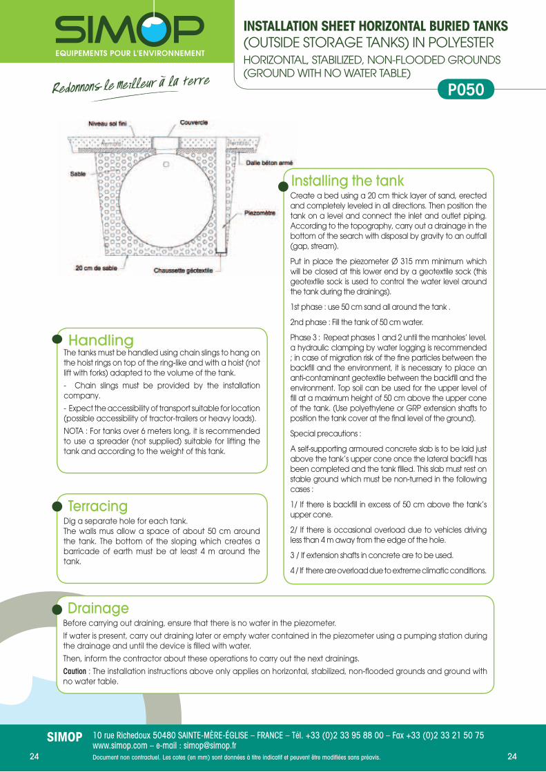
INSTALLATION SHEET HORIZONTAL BURIED TANKS(OUTSIDE STORAGE TANKS) IN POLYESTERHORIZONTAL, STABILIZED, NON-FLOODED GROUNDS (GROUND WITH NO WATER TABLE)
P050
DrainageBefore carrying out draining, ensure that there is no water in the piezometer.
If water is present, carry out draining later or empty water contained in the piezometer using a pumping station during the drainage and until the device is fi lled with water.
Then, inform the contractor about these operations to carry out the next drainings.
Caution : The installation instructions above only applies on horizontal, stabilized, non-fl ooded grounds and ground with no water table.
HandlingThe tanks must be handled using chain slings to hang on the hoist rings on top of the ring-like and with a hoist (not lift with forks) adapted to the volume of the tank.
- Chain slings must be provided by the installation company.
- Expect the accessibility of transport suitable for location (possible accessibility of tractor-trailers or heavy loads).
NOTA : For tanks over 6 meters long, it is recommended to use a spreader (not supplied) suitable for lifting the tank and according to the weight of this tank.
TerracingDig a separate hole for each tank.The walls mus allow a space of about 50 cm around the tank. The bottom of the sloping which creates a barricade of earth must be at least 4 m around the tank.
Installing the tankCreate a bed using a 20 cm thick layer of sand, erected and completely leveled in all directions. Then position the tank on a level and connect the inlet and outlet piping. According to the topography, carry out a drainage in the bottom of the search with disposal by gravity to an outfall (gap, stream).
Put in place the piezometer Ø 315 mm minimum which will be closed at this lower end by a geotextile sock (this geotextile sock is used to control the water level around the tank during the drainings).
1st phase : use 50 cm sand all around the tank .
2nd phase : Fill the tank of 50 cm water.
Phase 3 : Repeat phases 1 and 2 until the manholes’ level. a hydraulic clamping by water logging is recommended ; in case of migration risk of the fi ne particles between the backfi ll and the environment, it is necessary to place an anti-contaminant geotextile between the backfi ll and the environment. Top soil can be used for the upper level of fi ll at a maximum height of 50 cm above the upper cone of the tank. (Use polyethylene or GRP extension shafts to position the tank cover at the fi nal level of the ground).
Special precautions :
A self-supporting armoured concrete slab is to be laid just above the tank’s upper cone once the lateral backfi l has been completed and the tank fi lled. This slab must rest on stable ground which must be non-turned in the following cases :
1/ If there is backfi ll in excess of 50 cm above the tank’s upper cone.
2/ If there is occasional overload due to vehicles driving less than 4 m away from the edge of the hole.
3 / If extension shafts in concrete are to be used.
4 / If there are overload due to extreme climatic conditions.

Document non contractuel. Les cotes (en mm) sont données à titre indicatif et peuvent être modifi ées sans préavis. 25
10 rue Richedoux 50480 SAINTE-MÈRE-ÉGLISE – FRANCE – Tél. +33 (0)2 33 95 88 00 – Fax +33 (0)2 33 21 50 75www.simop.com – e-mail : [email protected]
SIMOP25
INSTALLATION SHEET POLYESTER TANKTECHNICAL SHEETS 6009, 6323, 6405 AND 6313ON CLAY AND/OR HYDROMORPHOUS SOILS (PRESENCE OF GROUNDWATER)
P053
TerracingBeware : the altimetric positioning of the tank must be calculated in such a way that the level of the ground water is not above that of the tank’s upper cone.Dig a separate hole for each tank and if necessary, push down the ground water until after backfi lling work for the device has been carried out.The walls must allow a space of about 50 cm around the tank. The bottom of the sloping which creates a barricade of earth must be at least 4 m around the tank.
DrainageComplete drainage in the end of the summer with cleaning and suction of the deposits from the bottom of the tank before fi lling up device in winter.
HandlingThe tanks must be handled using chain slings to hang on the hoist rings on top of the ring-like and with a hoist (not lift with forks) adapted to the volume of the tank.
- Chain slings must be provided by the installation company.
- Expect the accessibility of transport suitable for location (possible accessibility of tractor-trailers or heavy loads).
NOTA : For tanks over 6 meters long, it is recommended to use a spreader (not supplied) suitable for lifting the tank and according to the weight of this tank.
Installing the tankPour a reinforced concrete slab with a side implantation of Tor irons forming a loop, these irons will be used to fasten anchoring straps to counteract buoyancy.
On the concrete slab, Create a bed using stabilized sand with cement 200kg/m3 compacted to 20 cm high, erected and completely leveled in all directions. Then position the tank on a level and connect the inlet and outlet piping. Put in place the piezometer Ø 315 mm minimum which will be closed at this lower end by a geotextile sock (this geotextile sock is used to control the water level around the tank during the drainings).
Carrying out the lateral backfi ll :1st phase : use 50 cm stabilized sand with cement 200kg/m3 all around the tank. 2nd phase : Fill the tank of 50 cm water.Phase 3 : Repeat phases 1 and 2 until the manholes’ level. Notwithstanding lateral backfi ll : in the case of im-plantation on non-clay, without steep and stabilized ground, it is possible to replace stabilized sand with cement 200 kg/m3 by sand (no backfi ll with earth or other) .Carrying out superior backfi ll :Possibility of backfi lling with topsoil on a maximum height of 50 cm above the upper cone of the tank (Use polyethylene or GRP extension shafts to position the tank covers at the fi nal level of the ground).
Special precautionsA self-supporting armoured concrete slab is to be laid just above the tank’s upper cone once the lateral backfi l has been completed and the tank fi lled. This slab must rest on stable ground which must be non-turned in the following cases :
1/ If there is backfi ll in excess of 50 cm above the tank’s upper cone.
2/ If there is occasional overload due to vehicles driving less than 4 m away from the edge of the hole.
3 / If extension shafts in concrete are to be used.
4 / If there are overload due to extreme climatic conditions.
Note : Provide manhole compatible with any moving load.
Document non contractuel. Les cotes (en mm) sont données à titre indicatif et peuvent être modifi ées sans préavis.26
10 rue Richedoux 50480 SAINTE-MÈRE-ÉGLISE – FRANCE – Tél. +33 (0)2 33 95 88 00 – Fax +33 (0)2 33 21 50 75www.simop.com – e-mail : [email protected]
SIMOP
AEROBICRefers to a process performed in the presence of oxygen.
ANAEROBICRefers to a process that does not require oxygen.
ON-SITE SANITATIONSanitation performing collect, pretreatment, treatment, infi ltration or discharge of domestic wastewater buildings not connected to public sewer (see Decree dated May 6th 1996 on technical requirements, art.1).
GREASE TANK OR GREASE TRAPDevice used for grease separation by fl otation.
SLUDGESettled matter which settles to the bottom of the all-water tank.
ACTIVATED SLUDGETreatment process based on the activity of bacteria fl owing freely in especially oxygenated conditions.
BOD5Biochemical Oxygen Demand in 5 days (measure of the biodegradable pollution).
CHAIN DEFINITIONProcedure to choose the adapted on-site sanitation chain (type, size ...), according to the constraints of the studied plot (soil, slope, available area,...).
GREYWATERWater from bathrooms, kitchens, laundries, sinks,...
RAIN WATERWater from roofs and impervious surfaces. Rainwater should never be allowed in either the all-water tank or in the treatment system.
DOMESTIC WASTEWATERMixture of soils water and grey water.
SOILS WATERWater from the toilets.
EFFLUENTWastewater coming from the house or all-water tank.
SPREADING SYSTEMSystem collecting pretreated water (from the all-water tank for example) allowing their purifi cation by percolation into the ground or into a massive of fi ltered material restored.
UNDERGROUND SPREADINGSystem using ground as cleaner system and receiving environment.
TREATMENTComprehensive treatment of domestic effl uents which kill most of pollution before discharge to environement.
STUDY OF SOILIt determines the nature of the soil, particularly on the basis of the original material, depth, observed textures, permeability and potential logging appreciations, in order to evaluate the ability of the soil to purge and evacuate domestic wastewater.
OUTFALLReceiving environment of treated water.
GEOGRIDFabric with large mesh (from 500 microns up to about 1 mm for on-site sanitation) installed between two layers of granular material.
GEOTEXTILENonwoven material, permeable to water and air, insensitive to the action of bacteria or fungi, used for separating layers of materials of different particle sizes.
HYDROMORPHOUSRefers to a waterlogged area, either permanently or at certain times of the year.
INFILTRATION - PERCOLATIONTreatment process which consists in fi ltering the contaminated water through a visible sand body.
SUSPENDED SOLIDSOrganic or mineral particulate materials recoverable by fi ltration or centrifugation.
MIDWATER SURFACENatural or built environment where treated water of drained systems is discharged (ex streams).
WATER TABLEGroundwater capable of supplying springs or wells.
PEDOLOGYSoil science.
PERMEABILITYCharacteristic value of the ability of a soil to infi ltrate water.
HIGH AERATIONPipe which leads to the roof of the house, above the inhabited rooms, used for the ventilation of the all-water tank or septic tank.
Glossary

Document non contractuel. Les cotes (en mm) sont données à titre indicatif et peuvent être modifi ées sans préavis. 27
10 rue Richedoux 50480 SAINTE-MÈRE-ÉGLISE – FRANCE – Tél. +33 (0)2 33 95 88 00 – Fax +33 (0)2 33 21 50 75www.simop.com – e-mail : [email protected]
SIMOP
NOTE

Document non contractuel. Les cotes (en mm) sont données à titre indicatif et peuvent être modifi ées sans préavis.28
10 rue Richedoux 50480 SAINTE-MÈRE-ÉGLISE – FRANCE – Tél. +33 (0)2 33 95 88 00 – Fax +33 (0)2 33 21 50 75www.simop.com – e-mail : [email protected]
SIMOP
NOTE
Document non contractuel. Les cotes (en mm) sont données à titre indicatif et peuvent être modifi ées sans préavis.
10 rue Richedoux 50480 SAINTE-MÈRE-ÉGLISE – FRANCE – Tél. +33 (0)2 33 95 88 00 – Fax +33 (0)2 33 21 50 75www.simop.com – e-mail : [email protected]
SIMOP
NOTE

Mise
en
page
s Qu
ai d
es G
raph
’ – O
ctob
re 2
012.
10 rue Richedoux50480 SAINTE-MÈRE-ÉGLISE
FRANCETel. +33 (0)2 33 95 88 00 Fax +33 (0)2 33 21 50 75
www.simop.com e-mail : [email protected]
S.A.S. CAPITAL 1 525 000 eurosSIRET 304 971 641 00085RAINWATER TREATMENT
• Rainwater recovery• Oil Separators• Particulate decanters• Basin Facilities
Wastewater treatment• On-site Sanitation < 20 EH• On-site Sanitation > 20 EH• Grease separators
Roads & Networks• Soil Products• Road Equipment • Sanitation manholes • Pumping stations
Find all our products onwww.simop.com
SIMOP IS ALSO
Certifi é ISO 9001
Active member of IFAA