Use of Hawk ‘ORCA’ Sonar Bed/Hindered Level Transmitter … · Use of Hawk ‘ORCA’ Sonar...
7
A higher level of performance Use of Hawk ‘ORCA’ Sonar Bed/Hindered Level Transmitter to Maximize the Efficiency and Performance of Coal Preparation Plant Tailings Thickeners. Using the ORCA Sonar bed level transmitter to optimize “Coal Tailings Thickeners” by controlling both the compact bed level and the hindered/interface layer to maximize efficiency and performance. By monitoring the two independent interface densities we are able to provide reliable process feedback for: 1. Control of the underflow pump to optimize the bed density 2. Control of the flocculent and coagulant dosing systems if the ‘Clarometer’ fails The first process that should be automated on the tailings thickener is the discharge rate of the thickener underflow/ tailings disposal pump system to maintain the dense slurry compact bed at the optimum level in the thickener. By cascading the thickener bed level into the underflow/tailings disposal PID density control loop the feed to the underflow pumps will be of consistent density (as per thickener design) therefore minimizing unnecessary pumping of water to and from the tailings dam. To also minimize unnecessary pumping of water to and from the tailings dam: 1. The thickener underflow/tailings disposal system should only be initiated on plant start up and after the correct bed level has been established 2. The compact dense bed should only be pumped out of the thickener when the plant is going to be idle for and ex- tended time period. Note: It maybe necessary to purge the tailings lines using injection water on a thickener shutdown. A) Control of tailings disposal pump speed and water injection using cascaded density and thickener bed level. 1. Analogue output 1, from the ORCA Sonar controlling the heavy density compact bed interface. 2. The compact bed level output is also used as the datum in conjunction with the hindered/interface layer for provid- ing additional process feedback for controlling chemical dosing and alarms. Example block diagram compact bed level control
-
Upload
truongxuyen -
Category
Documents
-
view
228 -
download
2
Transcript of Use of Hawk ‘ORCA’ Sonar Bed/Hindered Level Transmitter … · Use of Hawk ‘ORCA’ Sonar...

A higher level of performance A higher level of performance
�
Use of Hawk ‘ORCA’ Sonar Bed/Hindered Level Transmitter to Maximize the Efficiency and Performance of Coal Preparation Plant Tailings Thickeners.
Using the ORCA Sonar bed level transmitter to optimize “Coal Tailings Thickeners” by controlling both the compact bed level and the hindered/interface layer to maximize efficiency and performance.
By monitoring the two independent interface densities we are able to provide reliable process feedback for:
1. Control of the underflow pump to optimize the bed density2. Control of the flocculent and coagulant dosing systems if the ‘Clarometer’ fails
The first process that should be automated on the tailings thickener is the discharge rate of the thickener underflow/tailings disposal pump system to maintain the dense slurry compact bed at the optimum level in the thickener.
By cascading the thickener bed level into the underflow/tailings disposal PID density control loop the feed to the underflow pumps will be of consistent density (as per thickener design) therefore minimizing unnecessary pumping of water to and from the tailings dam.
To also minimize unnecessary pumping of water to and from the tailings dam:
1. The thickener underflow/tailings disposal system should only be initiated on plant start up and after the correct bed level has been established
2. The compact dense bed should only be pumped out of the thickener when the plant is going to be idle for and ex-tended time period.
Note: It maybe necessary to purge the tailings lines using injection water on a thickener shutdown.
A) Control of tailings disposal pump speed and water injection using cascaded density and thickener bed level.
1. Analogue output 1, from the ORCA Sonar controlling the heavy density compact bed interface.2. The compact bed level output is also used as the datum in conjunction with the hindered/interface layer for provid-ing additional process feedback for controlling chemical dosing and alarms.
Example block diagram compact bed level control
A higher level of performance
�
A higher level of performance
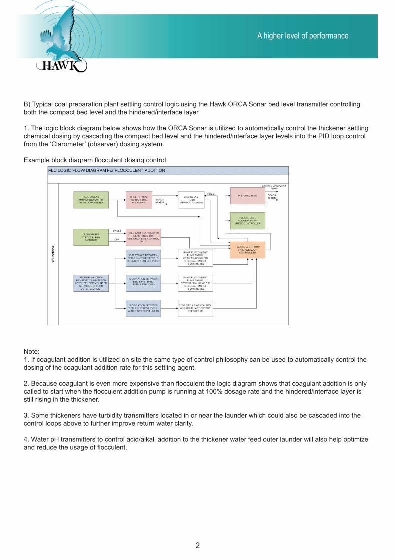
B) Typical coal preparation plant settling control logic using the Hawk ORCA Sonar bed level transmitter controlling both the compact bed level and the hindered/interface layer.
1. The logic block diagram below shows how the ORCA Sonar is utilized to automatically control the thickener settling chemical dosing by cascading the compact bed level and the hindered/interface layer levels into the PID loop control from the ‘Clarometer’ (observer) dosing system.
Example block diagram flocculent dosing control
Note: 1. If coagulant addition is utilized on site the same type of control philosophy can be used to automatically control the dosing of the coagulant addition rate for this settling agent.
2. Because coagulant is even more expensive than flocculent the logic diagram shows that coagulant addition is only called to start when the flocculent addition pump is running at 100% dosage rate and the hindered/interface layer is still rising in the thickener.
3. Some thickeners have turbidity transmitters located in or near the launder which could also be cascaded into the control loops above to further improve return water clarity.
4. Water pH transmitters to control acid/alkali addition to the thickener water feed outer launder will also help optimize and reduce the usage of flocculent.

A higher level of performanceA higher level of performance A higher level of performance
�
Channel 1: Compact bed level (Green trend)
Channel 2: Hindered interface layer (Grey trend)
Channel 3: Clarity of upper liquid zone (Orange trend)
Green profile: Compacted bed
White profile: Hindered interface layer
Example: Thickener settling characteristics (Good settling)
Typical 30 minutes trend for compact bed level and hindered/inter-face layer showing
1. Compact bed level, shows 1.018 m which shows a good level of bed guaranteeing an optimized underflow density.
2. Comparing the deviation distance between the compact bed (Green) and the hindered/interface layer (Grey trend) of 621 mm. This shows excellent settling conditions and a favourable flocculent dose rate.
Good settling characteristics

A higher level of performance
�
A higher level of performance
Example: Thickener settling characteristics (over flocculent dosing)
1. Compact bed level, shows 0.465 m which shows a good level of bed guaranteeing an optimized underflow density.
2. Comparing the deviation distance between the compact bed (Green) and the hindered/interface layer (Grey trend) of 386 mm. This shows excellent settling conditions but over flocculent dosing, increasing chemical costs and posibly affecting underflow density.
Channel 1: Compact bed level (Green trend)
Channel 2: Hindered interface layer (Grey trend)
Channel 3: Clarity of upper liquid zone (Orange trend)
Green profile: Compacted bed
White profile: Hindered interface layer
Good settling characteristics

A higher level of performanceA higher level of performance A higher level of performance
5
Good settling, flocculent dose ok Good settling, decreased deviationoverdosing flocculent Increased deviation, increased flocculent dose
Channel 1: Compact bed level (Green trend)
Channel 2: Hindered interface layer (Grey trend)
Channel 3: Clarity of upper liquid zone (Orange trend)
Green profile: Compacted bed
White profile: Hindered interface layer
1. Compact bed level is building and 0.418 mm will guarantee a good optimized underflow density.
2. Comparing the deviation between the compact bed and the hindered/interface layer on this trend shows typical settling changes caused by different ore bodies, clay etc.
Automatic changes to the flocculent dosing, based on monitoring the evident deviation process changes, will produce the most optimized performance for the thickener.
Example: Thickener settling characteris-tics (typical changes in settling character-istics)

A higher level of performance
6
A higher level of performance
Note: 1. If coagulant addition is utilized on site the same type of control philosophy can be used to automatically control the dosing of the coagulant addition rate for this settling agent.
2. Because coagulant is even more expensive than flocculent the logic diagram shows that coagulant addition is only called to start when the flocculent addition pump is running at 100% dosage rate and the hindered/interface layer is still rising in the thickener.
3. Some thickeners have turbidity transmitters located in or near the launder which could also be cascaded into the control loops above to further improve return water clarity.
4. Water pH transmitters to control acid/alkali addition to the thickener water feed outer launder will also help optimize and reduce the usage of flocculent.
Example block diagram coagulent dosing control
Tailings ThickenerTailings Thickener

A higher level of performanceA higher level of performance A higher level of performance
�
3 Crystal ArrayORCA Sonar Sensor
7 Crystal ArrayORCA Sonar Sensor
Typical Bed Level Control Thickener, CCD, Clarifier
Green trend shows bed level (output 1)Over 8hr period density is 10G/L
ORCA Sonar Transmitter provides 2 outputs‘Bed Level’ Position (output 1) and‘Clarity’ (output 2)TME ‘Clarity’ output is a 4-20mA outputproportional to the percentage of suspended solids between the sonar sensor and the ‘Bed Level’ interface. This output could beused in a PID Control of automatic floc dosing.
RED Trend shows changes in clarity over an 8hr period (output2)Large spikes show major variationsin inflow media to the thickener.
FEEDWELL
ClearometerWhite Trend
Clearometer
ORCA Sonar Transducer Option
CLARIFIED ZONE
FREE SETTLING ZONE
HINDERED ZONE
COMPACTED ZONE
Single Crystal ArrayORCA Sonar Sensor
Mounting Bracket and Electro Actuator Cleaner
Copyright Hawk Measurement Systems 2009
Hawk’s ORCA Sonar Sensors
Sonar transducer penetration capability depending on power level.
Single crystal: PN Clarifier, clarifiers, tailings dam3 crystal array: Tailings thickeners, paste thickener, hi-rate thickener, CCD’s7 crystal array: Concentrate thickeners, CCD’s
Mining Thickeners - choosing the correct transducer
Tailings Thickener (Surface scum boom)
Contact Hawk Measurement Systems AustraliaPhone: +61 3 9873 [email protected]
Hawk Measurement USPhone: +1 888 429 [email protected]
For global representatives: www.hawkmeasure.com