Use in spheroidal cast iron Approval update - Fatigue …€¦ · · 2014-01-20devices to cast...
13
Operating instructions: DX 450-SCT Early strength of sprayed concrete with Hilti DX 450-SCT, Edition 9/2011 1 Hilti X-BT Threaded Fastener Specification Supplement 11/2011 Use in spheroidal cast iron Approval update - Fatigue classification November 2011
Transcript of Use in spheroidal cast iron Approval update - Fatigue …€¦ · · 2014-01-20devices to cast...
Operating instructions: DX 450-SCT
Early strength of sprayed concrete with Hilti DX 450-SCT, Edition 9/2011 1
Hilti X-BT Threaded Fastener Specification Supplement 11/2011 Use in spheroidal cast iron Approval update - Fatigue classification
November 2011

X-BT Specification Suppl. 11/2011
Hilti X-BT Threaded Fastener Specification, Supplement 11/2011 1
Content
Preface 2
1 Technical data for X-BT fastenings made to cast iron with 3 spheroidal graphite
1.1 Cast iron specification 3
1.2 Fastening tool and components 4
1.3 Load data 5
1.4 Connection types and application range 6
1.5 Grounding and bonding restrictions 6
1.6 Performance review 7
2 Approval update 9 2.1 Modifications and updates since December 2011 9
2.2 Specifics on fatigue classification 10
2.2.1 Fatigue classification in compliance with Eurocode 3 10 (EN 1993-1-9)
2.2.1 Approved fatigue categories by GL (Germanischer Lloyd) 11 and DNV (Det Norske Veritas)
3 Literature 12

X-BT Specification Suppl. 11/2011
Hilti X-BT Threaded Fastener Specification, Supplement 11/2011 2
Preface The specification of the Hilti X-BT threaded fastener is published in the brochure Hilti X-BT Threaded Fas-tener Specification, issue December 2010 [1].
This specification contains
Application description Technical data Method statement Description of technical performance Approval survey Customer testimonials
This supplement predominantly deals with the extension of the use of X-BT fasteners which are driven to cast iron base materials. Additionally an approval update compared with the status from end of 2010 [1] will be given.
In general this supplement needs to be read in conjunction with the Hilti X-BT Threaded Fastener Specifica-tion, issue December 2010 [1]. Figure 1 gives an overview of the X-BT fasteners with sealing washer. Fur-thermore, Figure 1 summarizes the most relevant technical data when the X-BT fasteners are driven into unalloyed carbon steel.
X-BT M10-24-6 SN12-R X-BT W10-24-6 SN12-R
X-BT M8-15-6 SN12-R
X-BT M6-24-6 SN12-R X-BT W6-24-6 SN12-R
Typical application: Fastening of cables, cable ladders,
T-bars, grounding
Typical application: Fastening of grating and
Hilti M-channels
Typical application: Fastening of electrical junction
boxes
Recommended working loads according to [1] and [2]:
Base material S235 (A36) : Tension: Nrec = 1.8 kN (405 lbs), Shear: Vrec = 2.6 kN (517 lbs) Base material S355 (Grade 50) : Tension: Nrec = 2.3 kN (584 lbs), Shear: Vrec = 3.4 kN (764 lbs)
Figure 1. Survey of Hilti X-BT threaded fasteners With respect to further details on the fasteners, method statement and quality control it is referenced to [1].
When driving the X-BT fasteners into cast iron components, the method itself, the cartridge recommendation, the use of the respective tool and the stand-off requirements remain unchanged, details see [1].

X-BT Specification Suppl. 11/2011
Hilti X-BT Threaded Fastener Specification, Supplement 11/2011 3
1. Technical data for X-BT fastenings made to cast iron with spheroi-dal graphite
1.1 Cast iron specification
Components made from cast iron with spheroidal graphite are typically used in the nacelle of wind towers. The preferred grade is EN-GJS-400-18-LT according to EN 1563 with a minimum ultimate strength of 400 N/mm² (for thickness t 30 mm), a minimum fracture strain A of 18 % and with impact toughness properties suitable for use in cold temperatures. The use of cast iron with spheroidal graphite allows economical production of complex machinery parts combined with ductile material behaviour.
The presence of spherical graphite is required to allow the casting process. Figure 2 shows a representative example of a micro section of cast iron EN-GJS-400-18-LT. The distribution of the spheroidal graphite in the ferritic matrix is clearly visible.
Figure 2. Micro section of cast iron EN-GJS-400-18LT: Spheroidal graphite embedded in ferritic matrix
The cast iron needs to meet the following specification given in Table 1. The listed carbon content and micro-structure is typical for EN-GJS-400-18-LT used in the nacelle of wind towers.
Table 1. Requirements of spheroidal graphite cast iron base material
Subject Requirements
Cast iron Spheroidal graphite cast iron according to EN 1563
Strength class EN-GJS-400 to EN-GJS-600 according to EN 1563
Chemical analysis and amount of carbon
3.3 - 4.0 mass percentage
Microstructure Form IV to VI (spherical) according to EN ISO 945-1:2010 Minimum size 7 according to Figure 4 of EN ISO 945-1:2010
Material thickness tII 20 mm
X-BT Specification Suppl. 11/2011
Hilti X-BT Threaded Fastener Specification, Supplement 11/2011 4
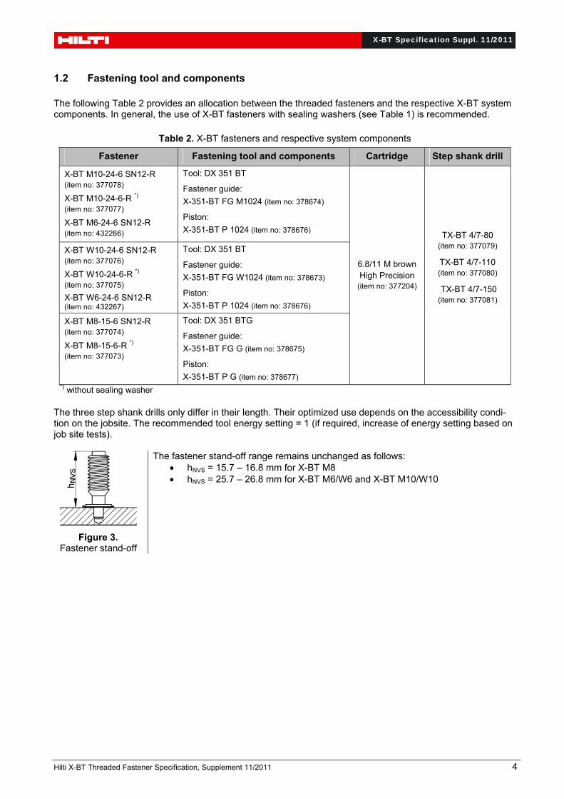
1.2 Fastening tool and components The following Table 2 provides an allocation between the threaded fasteners and the respective X-BT system components. In general, the use of X-BT fasteners with sealing washers (see Table 1) is recommended.
Table 2. X-BT fasteners and respective system components
Fastener Fastening tool and components Cartridge Step shank drill
X-BT M10-24-6 SN12-R (item no: 377078)
X-BT M10-24-6-R *) (item no: 377077)
X-BT M6-24-6 SN12-R (item no: 432266)
Tool: DX 351 BT
Fastener guide:
X-351-BT FG M1024 (item no: 378674)
Piston:
X-351-BT P 1024 (item no: 378676)
6.8/11 M brown High Precision
(item no: 377204)
TX-BT 4/7-80 (item no: 377079)
TX-BT 4/7-110 (item no: 377080)
TX-BT 4/7-150 (item no: 377081)
X-BT W10-24-6 SN12-R (item no: 377076)
X-BT W10-24-6-R *) (item no: 377075)
X-BT W6-24-6 SN12-R (item no: 432267)
Tool: DX 351 BT
Fastener guide:
X-351-BT FG W1024 (item no: 378673)
Piston:
X-351-BT P 1024 (item no: 378676)
X-BT M8-15-6 SN12-R (item no: 377074)
X-BT M8-15-6-R *) (item no: 377073)
Tool: DX 351 BTG
Fastener guide:
X-351-BT FG G (item no: 378675)
Piston:
X-351-BT P G (item no: 378677) *) without sealing washer The three step shank drills only differ in their length. Their optimized use depends on the accessibility condi-tion on the jobsite. The recommended tool energy setting = 1 (if required, increase of energy setting based on job site tests).
Figure 3. Fastener stand-off
The fastener stand-off range remains unchanged as follows: hNVS = 15.7 – 16.8 mm for X-BT M8 hNVS = 25.7 – 26.8 mm for X-BT M6/W6 and X-BT M10/W10

X-BT Specification Suppl. 11/2011
Hilti X-BT Threaded Fastener Specification, Supplement 11/2011 5
1.3 Load data
Table 3 summarizes the recommended working loads for the X-BT fasteners driven into cast iron.
Table 3. Recommended loads for X-BT fasteners and cast iron base material
Loading direction Recommended loads
Tension Nrec = 0.5 kN (115 lbs)
Shear Vrec = 0.75 kN (170 lbs)
Bending Mrec = 8.2 Nm (6 ftlb)
The installation torque Trec amounts to 8 Nm (5.9 ftlb).
Conditions for the recommended loads:
Global factor of safety for static pull-out: 3 (based on 5% fractile), 5 (based on mean value) Minimum edge distance = 6 mm (1/4”) Dynamic load variation is covered Table 4 shows the recommended interaction formula in case of combined loading:
Table 4. Recommended interaction formula
Combined loading situation Interaction formula
V – N (shear and tension) 2.1recrec N
N
V
V with 0.1
recV
V and 0.1
recN
N
V – M (shear and bending) 2.1recrec M
M
V
V with 0.1
recV
V and 0.1
recM
M
N – M (tension and bending) 0.1recrec M
M
N
N
V – N – M (shear, tension and bending)
0.1recrecrec M
M
N
N
V
V
V, N and M correspond with the maximum working loads (see internal forces in Table 5) acting on the fas-tening. Note: Table 4 also applies in case of carbon steel or stainless base material.

X-BT Specification Suppl. 11/2011
Hilti X-BT Threaded Fastener Specification, Supplement 11/2011 6
1.4 Connection types and application range
Table 5 summarizes the possible types of connection, the corresponding loading and the respective range of application.
Table 5. Types of connection and corresponding loading conditions, range of application
Type of connection Type of loading Range of application
Connections of steel sheets or plates to cast iron base
material
tI
tII
e
Lateral shear loading
V
Fastened material (component I):
Structural carbon steel or corrosion re-sistant steel according to EN 10025, EN 10346 and EN 10088-2 with:
Rm 330 N/mm2
tI for studs with sealing washer: 1 mm tI 14 mm for X-BT M6/W6 2 mm tI 7 mm for X-BT M8 2 mm tI 15 mm for X-BT M10/W10
tI for studs without sealing washer:
10 mm tI 15 mm for X-BT M10/W10 Cast iron base material (component II): Spheroidal graphite cast irons according to EN 1563 with:
400 N/mm2 Rm 720 N/mm2
Microstructure and chemical analysis as given in Table 1
tII 20 mm
Minimum edge distance: e 6 mm
Tensile loading
N/2N/2
Type of connection Type of loading Range of application
Connection of installation devices to cast iron base
material
Shear, tension and bending loading
Cast iron base material (component II): Spheroidal graphite cast irons according to EN 1563 with:
400 N/mm2 Rm 720 N/mm2
Microstructure chemical analysis as given in Table 1
tII 20 mm
Minimum edge distance: e 6 mm
e
tII
N
VM
1.5 Grounding and bonding restrictions
No corresponding experimental investigations have been made so far. There, the use of X-BT fasteners for grounding and bonding application is not covered, in case the fasteners are driven to cast iron components.

X-BT Specification Suppl. 11/2011
Hilti X-BT Threaded Fastener Specification, Supplement 11/2011 7
1.6 Performance review
In order to investigate the influence of cast iron base material on the performance of X-BT fasteners a com-prehensive test program was run. The scope of the program included the following experimental investigations (summary and assessment in [3]):
Static pullout tests Static shear and bending tests Tension fatigue tests
Tests to cover the effect of the edge distance Tests to cover the effect of the cast iron surface
Compared with the performance of X-BT fasteners in unalloyed structural steel (see Figure 1, [1] and [2]), the recommended load values are smaller due to the presence of the graphite in the cast iron. As with unalloyed structural steel, reliable anchorage of the X-BT fastener develops also in case of cast iron base material. The anchorage is also caused by predominantly friction welding between the fastener shank and the ferritic or perlitic matrix of the cast iron. However, the presence of the graphite reduces the effective contact area, which explains the reduction of the pullout strength.
Furthermore, the recommended loads cover implicitly effects of dynamic and variable loading on the fastener. This statement is based on the results of tension fatigue tests, which were performed to investigate the ro-bustness of the anchorage of X-BT fasteners in cast iron, see Figure 4 and 5.
F
t
cast iron
X-BT fastener
fatigue loading
tens
ion
F
t
Fmax
Fmin
F
Fmin = 0.1 kN (const.)
Figure 4. Principle sketch of cyclic tension tests
Figure 5. Servo-hydraulic test setup for tension fatigue tests

X-BT Specification Suppl. 11/2011
Hilti X-BT Threaded Fastener Specification, Supplement 11/2011 8
Conclusions from the cyclic tension tests: The anchorage of the X-BT does not work loose. In none of the tests pull-out of the fastener from the cast
iron was the controlling mode of failure. Failure was controlled by fatigue fracture of the stainless stud material. The fractures occurred at upper
loads significantly beyond the recommended tension load of 0.5 kN. For final verification and with respect to the reported design life of wind towers, two fatigue tests were
performed with an upper load of 1.0 kN (which is double the recommended tension load) and a target number of 200 million load cycles.
Both long run samples passed the test without any damage, neither to the fastener material nor to the anchorage. Residual static pullout tests of these two samples resulted in a pullout strength beyond 5 kN.
The test results clearly verify reliable X-BT fastenings to cast iron EN-GJS-400-18LT used in the nacelle of wind towers.
Figure 6 shows a graph of the fatigue test results performed with X-BT fasteners. The load-level of the run-outs is by far beyond the recommended working load of 0.5 kN, especially see the two run-outs at 200 million load cycles with an upper load of 1.0 kN.
104 105 106 107 2.108
Number of cycles N
Upper load Fmax [kN]
0.5
1
2
3
456
Test with failuresTests without failure (run-outs) mean regression curve characteristic fatigue strength
Recommended working load: 0.5 kN
Fasteners: X-BT M8-15-6 SN12-R or X-BT M10-24-6 SN12-RBase material: EN-GJS-400-18-LT
Figure 6. Results of cyclic tension tests It is further planned to add the use of X-BT fasteners on cast iron components into the X-BT Type Approvals issued by GL [4] and DNV [5].
X-BT Specification Suppl. 11/2011
Hilti X-BT Threaded Fastener Specification, Supplement 11/2011 9
2 Approval update
2.1 Modifications and updates since December 2011
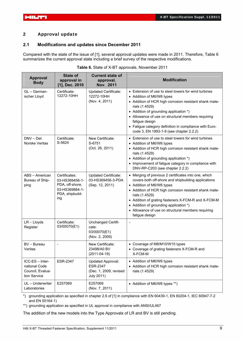
Compared with the state of the issue of [1], several approval updates were made in 2011. Therefore, Table 6 summarizes the current approval state including a brief survey of the respective modifications.
Table 6. State of X-BT approvals, November 2011
Approval Body
State of approval in
[1], Dec. 2010
Current state of approval, Nov. 2011
Modification
GL – German-ischer Lloyd
Certificate: 12272-10HH
Updated Certificate: 12272-10HH (Nov. 4, 2011)
Extension of use to steel towers for wind turbines Addition of M6/W6 types Addition of HCR high corrosion resistant shank mate-
rials (1.4529) Addition of grounding application *) Allowance of use on structural members requiring
fatigue design Fatigue category definition in compliance with Euro-
code 3, EN 1993-1-9 (see chapter 2.2.2)
DNV – Det Norske Veritas
Certificate: S-5624
New Certificate: S-6751 (Oct. 26, 2011)
Extension of use to steel towers for wind turbines Addition of M6/W6 types Addition of HCR high corrosion resistant shank mate-
rials (1.4529) Addition of grounding application *) Improvement of fatigue category in compliance with
DNV-RP-C203 (see chapter 2.2.2)
ABS – American Bureau of Ship-ping
Certificates: 03-HS369456-1-PDA, off-shore, 03-HS369884-1-PDA, shipbuild-ing
Updated Certificate: 03-HS369456-3-PDA (Sep. 12, 2011)
Merging of previous 2 certificates into one, which covers both off-shore and shipbuilding applications
Addition of M6/W6 types Addition of HCR high corrosion resistant shank mate-
rials (1.4529) Addition of grating fasteners X-FCM-R and X-FCM-M Addition of grounding application *) Allowance of use on structural members requiring
fatigue design
LR – Lloyds Register
Certificate: 03/00070(E1)
Unchanged Certifi-cate: 03/00070(E1) (Nov. 2, 2009)
-
BV – Bureau Veritas
- New Certificate: 23498/A0 BV (2011-04-19)
Coverage of M8/M10/W10 types Coverage of grating fasteners X-FCM-R and
X-FCM-M
ICC-ES – Inter-national Code Council, Evalua-tion Service
ESR-2347 Updated Approval: ESR-2347 (Dec. 1, 2009, revised July 2011)
Addition of M6/W6 types Addition of HCR high corrosion resistant shank mate-
rials (1.4529)
UL – Underwriter Laboratories
E257069 E257069 (Nov. 7, 2011)
Addition of M6/W6 types **)
*) grounding application as specified in chapter 2.6 of [1] in compliance with EN 60439-1, EN 60204-1, IEC 60947-7-2 and EN 50164-1)
**) grounding application as specified in UL approval in compliance with ANSI/UL467
The addition of the new models into the Type Approvals of LR and BV is still pending.

X-BT Specification Suppl. 11/2011
Hilti X-BT Threaded Fastener Specification, Supplement 11/2011 10
2.2 Specifics on fatigue classification 2.2.1 Fatigue classification in compliance with Eurocode 3 (EN 1993-1-9) Hilti ran a comprehensive fatigue test program in order to classify the constructional detail “Structural steel base material with the Hilti powder-actuated fastener X-BT” in compliance with the Eurocode 3 (EN 1993-1-9, [7]). A corresponding evaluation was made by Prof. U. Kuhlmann and H.P. Günther from the University of Stuttgart (Report No. 2010-57X [6]).
Table 7. Recommendation of fatigue detail category according to EN 1993-1-9:2005 [6, 1]
Detail category
Constructional detail Description Requirements
90
Hilti X-BT powder-actuated fasteners with pre-drilled hole in structural steel base material.
Imperfect fastener installations as e.g. pulled-out fasteners or pre-drilled holes without fasten-ers are covered.
∆σ to be calculated by the gross cross-section.
Installation, static loading and spacing of fasteners only in accordance with the require-ments of the Hilti X-BT threaded fastener specifica-tion [1]
Plate thickness t 8 mm
Edge distance 15 mm
100 m = 5
Category 90 corresponds with a standard category according to Table 7.1 of EN 1993-1-9 [7] with a slope m = 3 for cycles N 5 million cycles and a slope m = 5 for N > 5 million cycles (see Figure 8). Category 100 (m = 5) with a constant slope m = 5 for N 100 million cycles represents a possible, alternate option in compliance with the Eurocode 3. The latter is recommended in case of low amplitude high cycle fatigue load-ing. When using a fatigue assessment procedure based on a linear damage accumulation a mixture of both categories is not allowed.
The structural steel grades S235 up to S460 according to EN 10025-2, EN 10025-3, EN 10025-4 and EN 10225 are covered. These grades include thermo mechanically rolled fine grain steels.
The following Figure 7 shows a summary of all test data including the fatigue classification in keeping with the Eurocode 3.
Fatigue test results Base material with Hilti X-BT fasteners
Cycle Life N
Str
ess
Ra
ng
e
[N/m
m²]
EC3-90 EC3-100/m=5 Test results Run-outs
104 5 105 5 106 2 5 107
50
75
100
125
150
175
200
225
250
275
300325350375400425
Fatigue categories according to Eurocode 3 with constant amplitude fatigue limit at 5 million cycles
Figure 7. Test data compared with fatigue recommendation according to Eurocode 3 [6, 1]
X-BT Specification Suppl. 11/2011
Hilti X-BT Threaded Fastener Specification, Supplement 11/2011 11
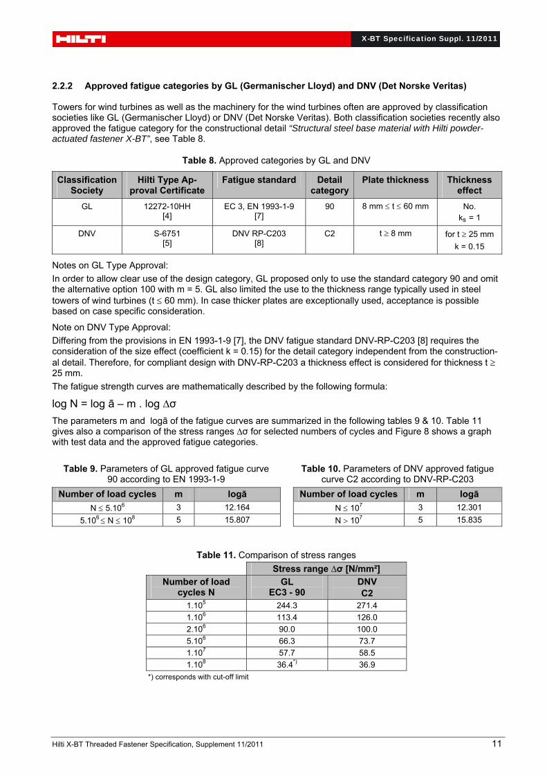
2.2.2 Approved fatigue categories by GL (Germanischer Lloyd) and DNV (Det Norske Veritas) Towers for wind turbines as well as the machinery for the wind turbines often are approved by classification societies like GL (Germanischer Lloyd) or DNV (Det Norske Veritas). Both classification societies recently also approved the fatigue category for the constructional detail “Structural steel base material with Hilti powder-actuated fastener X-BT”, see Table 8.
Table 8. Approved categories by GL and DNV
Classification Society
Hilti Type Ap-proval Certificate
Fatigue standard Detail category
Plate thickness Thickness effect
GL 12272-10HH [4]
EC 3, EN 1993-1-9 [7]
90 8 mm t 60 mm No. ks = 1
DNV S-6751 [5]
DNV RP-C203 [8]
C2 t 8 mm for t 25 mm
k = 0.15
Notes on GL Type Approval:
In order to allow clear use of the design category, GL proposed only to use the standard category 90 and omit the alternative option 100 with m = 5. GL also limited the use to the thickness range typically used in steel towers of wind turbines (t 60 mm). In case thicker plates are exceptionally used, acceptance is possible based on case specific consideration.
Note on DNV Type Approval:
Differing from the provisions in EN 1993-1-9 [7], the DNV fatigue standard DNV-RP-C203 [8] requires the consideration of the size effect (coefficient k = 0.15) for the detail category independent from the construction-al detail. Therefore, for compliant design with DNV-RP-C203 a thickness effect is considered for thickness t 25 mm.
The fatigue strength curves are mathematically described by the following formula:
log N = log ā – m . log ∆σ The parameters m and logā of the fatigue curves are summarized in the following tables 9 & 10. Table 11 gives also a comparison of the stress ranges ∆σ for selected numbers of cycles and Figure 8 shows a graph with test data and the approved fatigue categories.
Table 9. Parameters of GL approved fatigue curve 90 according to EN 1993-1-9
Table 10. Parameters of DNV approved fatigue curve C2 according to DNV-RP-C203
Number of load cycles m logā Number of load cycles m logā
N 5.106 3 12.164 N 107 3 12.301
5.106 N 108 5 15.807 N 107 5 15.835
Table 11. Comparison of stress ranges Stress range ∆σ [N/mm²]
Number of load cycles N
GL EC3 - 90
DNV C2
1.105 244.3 271.4
1.106 113.4 126.0
2.106 90.0 100.0
5.106 66.3 73.7
1.107 57.7 58.5
1.108 36.4*) 36.9
*) corresponds with cut-off limit

X-BT Specification Suppl. 11/2011
Hilti X-BT Threaded Fastener Specification, Supplement 11/2011 12
Fatigue classification Base material with Hilti X-BT fasteners
Cycle Life N
Str
ess
Ra
ng
e
[N/m
m²]
GL, EC3-90 DNV, C2 Test results Run-outs
104 5 105 5 106 2 5 107 108
10
20
30
40
5060708090
100
200
300
400
500600700800900
1000
Figure 8. Test data compared with approved GL and DNV fatigue categories
3 Literature
[1] Hilti Corporation (2010): Hilti X-BT Threaded Fastener Specification, Edition December 2010
[2] Hilti Corporation (2009): Hilti Direct Fastening Technology Manual, Edition 11/2009
[3] Kuhlmann, U., Günther, H-P. (2011): Hilti powder-actuated fastener X-BT in combination with the Hilti fastening tools DX 351 BT/BTG for the use in cast iron base material according to EN 1563, Evalua-tion Report, Institut für Konstruktion und Entwurf, Stahl- Holz- und Verbundbau, University of Stuttgart, Report Nr. 2011-24X, Oct. 11, 2011.
[4] GL, Germanischer Lloyd (2011): Approval Certificate: 12272-10HH, Mechanical Fastening Systems, Hilti X-BT stainless steel threaded fasteners, Hamburg, 2011-11-04
[5] DNV, Det Norske Veritas (2011): Type Approval Certificate No. S-6751, Structural Connecting Ele-ments: X-BT threaded fasteners, Grating fasteners X-FCM-R, X-FCM-M, Høvik, 2011-10-26
[6] Kuhlmann, U., Günther, H-P. (2010): Fatigue strength of the constructional detail “Structural steel base material with the Hilti powder-actuated fastener X-BT” in compliance with Eurocode 3 Part 1-9 (EN 1993-1-9), Institut für Konstruktion und Entwurf, Stahl- Holz- und Verbundbau, University of Stuttgart, Report Nr. 2010-57X, December 28, 2010
[7] EN 1993-1-9:2005 (2005): Eurocode 3: Design of steel structures – Part 1-9: Fatigue, European Standard, May 2005
[8] DNV-RP-C203, Det Norske Veritas (2010): Recommended Practice: Fatigue design of offshore steel structures, April 2010