USB/RS232 TO ccTalk COMMUNICATION BOARD · USB/RS232 to CcTalk COMMUNICATION BOARD 18/04/2016 3 3....
13
USB/RS232 to CcTalk COMMUNICATION BOARD 18/04/2016 USB/RS232 TO ccTalk COMMUNICATION BOARD Technical Information
Transcript of USB/RS232 TO ccTalk COMMUNICATION BOARD · USB/RS232 to CcTalk COMMUNICATION BOARD 18/04/2016 3 3....

USB/RS232 to CcTalk COMMUNICATION BOARD 18/04/2016
USB/RS232 TO ccTalk
COMMUNICATION
BOARD Technical Information

USB/RS232 to CcTalk COMMUNICATION BOARD 18/04/2016
The information contained in this technical manual is provided as support to the use of the product and its tools. Azkoyen S.A.
dedicates all the efforts in assuring the reliability and correctness of the information and data contained in this technical manual,
but we cannot guarantee in any way that is totally free of typesetter errors or omissions. Due to the continuous improvement in
our products, this information is subjected to changes without previous notification. The use of our products, accessories and
tools outside the specifications that are detailed, will be of exclusive responsibility of the user and Azkoyen S.A. will not be
responsible of an incorrect use or outside of specifications. Please pay attention to the security recommendations. This product is
protected by international patents. It is prohibited the total or partial reproduction of this manual without the written consent of
Azkoyen S.A.
Manual code: 81043530
ATTENTION: Read this technical manual carefully before
installing or carrying out any operation with the board.
Legal warning
USB/RS232 to CcTalk COMMUNICATION BOARD 18/04/2016
VERSION HISTORY
Date Version 18.04.2016 V1 Creation of document

USB/RS232 to CcTalk COMMUNICATION BOARD 18/04/2016
1. INTRODUCTION ..................................................................................................... 1
2. TERMINAL DIAGRAM .......................................................................................... 1
3. FEATURES AND CONNECTIONS ........................................................................ 3
3.1. CCTALK BUS CONNECTORS (A1-A5) ............................................................ 3
3.2. POWER SOURCE CONNECTOR (A6) .............................................................. 4
3.3. SERIAL COMMUNICATION ............................................................................. 5
3.3.1. USB PHYSICAL CONNECTION (A7) ............................................................ 5
3.3.2. RS232 PHYSICAL CONNECTION (A8) ........................................................ 6
3.3.3. USB/RS232 DATA TRANSMISSION FORMAT ........................................... 6
4. SET-UP AND LAUNCH .......................................................................................... 7

USB/RS232 to CcTalk COMMUNICATION BOARD 18/04/2016 1
1. INTRODUCTION This adapter board converts communications from RS232 or USB serial protocol to
ccTalk protocol. This way, it offers the possibility to connect a Master device using
serial protocol communication to control and monitor ccTalk devices plugged into a
bus.
Image 1: Adapter board RS232/USB to CCTalk
Image 2: Protocol conversion
2. CONNECTORS DIAGRAM
The communication board has the following connectors:
- A1 – A5: 5 2X5 pins ccTalk connectors. They are internally connected, so they
can be used interchangeably.
- A6: 12/24 V power supply.
- A7: Type B USB port.
- A8: RS232 port.
- A9: Power switch port. It allows the use of a power switch. If no switch is used,
a jumper must be connected.
- A10: Ground connector. It allows connecting the board to the grounding
system.

USB/RS232 to CcTalk COMMUNICATION BOARD 18/04/2016 2
Image 3: PCB connectors
Connector Description
A1 2x5 pin ccTalk Connector
A2 2x5 pin ccTalk Connector
A3 2x5 pin ccTalk Connector
A4 2x5 pin ccTalk Connector
A5 2x5 pin ccTalk Connector
A6 Power supply
A7 USB
A8 RS232 serial
A9 Power switch
A10 Ground
Table 1: List of connectors

USB/RS232 to CcTalk COMMUNICATION BOARD 18/04/2016 3
3. FEATURES AND CONNECTIONS Below there is a description of each of the connectors in the adapter board.
3.1. CCTALK BUS CONNECTORS (A1-A5) Each of the 5 ccTalk connectors in the adapter board has 10 pins distributed in 2 rows.
Their shape allows them to be plugged only in one correct position. The following
image shows their shape and the position of each pin.
Image 4: ccTalk connector pin out
PIN Description
1 DATA
2 GND
3 -
4 GND
5 -
6 -
7 VCC
8 GND
9 -
10 VCC
Table 2: ccTalk communication pin out

USB/RS232 to CcTalk COMMUNICATION BOARD 18/04/2016 4
3.2. POWER SOURCE CONNECTOR (A6) A 12 or 24 V power source must be connected to the board. The following table shows
the requirements of the power source, and the connector type it must have.
Table 3: Power source specifications
Power source
specifications
Input
Voltage 100 - 240 V AC
Current Depending on the source
Output
Voltage 12/24 V DC
Max. current 4 A
Power connector on the
board
• External diameter: 6,3 mm
• Male internal diameter: 2,1 mm
• + Vin = 12/24 V
• - Vin = GND
Power source connector
• External diameter: 5,5 mm
• Female internal diameter: 2,1 mm de
• 11 mm length, “+” center:
• + Vout = 12/24 V
• - Vout = GND

USB/RS232 to CcTalk COMMUNICATION BOARD 18/04/2016 5
3.3. SERIAL COMMUNICATION This adapter board has both RS232 and USB serial communication connector, although
the communication protocols are defined under the “ccTalk Serial Communication
Protocol Generic Specification”.
3.3.1. USB PHYSICAL CONNECTION (A7)
Table 4: USB communication specification
Version USB 1.1/USB 2.0
Description Universal Serial Bus (USB)
Connector Type Type B
Pin out PIN1-VBUS, PIN2-D-, PIN3-D
+, PIN4-GND
Connection type/
wiring(USB)
4-pins
Max. wire length USB
(at max. speed)
Max. delay: 5,2 ns/m
Max. length = 5 meters

USB/RS232 to CcTalk COMMUNICATION BOARD 18/04/2016 6
3.3.2. RS232 PHYSICAL CONNECTION (A8)
Table 5: RS232 serial communication specification
3.3.3. USB/RS232 DATA TRANSMISSION FORMAT
Baud rate 9600 bauds
Start bits 1
Data bits 8
Parity No parity
Stop bits 1
Flow control
No
Interface type Adapter without ECO
Table 6: Transmission parameters
Version RS2-232/EIA-232
Description RS-232 (Recommended Standard 232) Serial Port
Connector type D-SUB 9 Female
Pin out PIN2-TXD, PIN3-RXD, PIN5-GND
Connection type/ wiring
(master)
3-pin/ null modem
RS232 MASTER
Max. serial cable length
(at 9600bd)
Max. capacitance = 2.500pF
Standard quality cable = 15 meters
Lower capacitance cable = up to 30 meters

USB/RS232 to CcTalk COMMUNICATION BOARD 18/04/2016 7
4. SET-UP AND LAUNCH The board can be connected to a computer both through a USB connection or a RS232
serial connection. Follow these steps in order to set it up:
a) Plug the power source to the adapter board. Doing so, the LED located
between the USB and the power ports will turn on. Remember to connect
either a switch (a door switch, for instance) or the provided jumper in the
“power switch” port (A9). The board can also be connected to the ground
through the A10 port.
b) Proceed to connect the ccTalk devices in the 2X5 pin ports (there is no order or
position preference).
Image 5: Adapter board in use
CONNECTION THROUGH USB
a) Connect the USB cable to the board and a free USB port in your computer
b) The connection will appear as a virtual COM port in the computer. A manual
installation of the drivers may be required for its normal functioning. They can
be downloaded in the following web site:
http://www.ftdichip.com/Drivers/VCP.htm.
CONNECTION THROUGH RS232
a) Connect the RS232 cable to the board and a free serial port in your computer. If
both RS232 and USB ports are connected, the communication will be made
through the USB connection.
b) The connection will appear as a COM port in the computer.
c) Launch Azkoyen GestorCCTalk program (also named ccTalkManager). Once it is
loaded, the followings connection parameters must be configured:
USB/RS232 to CcTalk COMMUNICATION BOARD 18/04/2016 8
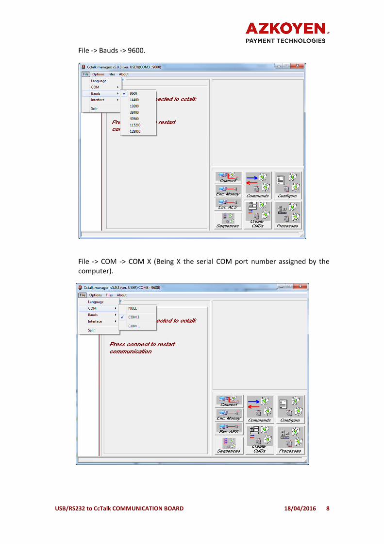
File -> Bauds -> 9600.
File -> COM -> COM X (Being X the serial COM port number assigned by the
computer).

USB/RS232 to CcTalk COMMUNICATION BOARD 18/04/2016 9
In case the corresponding COM port number does not appear in the menu,
choose the option “COM…” (File -> COM -> COM…) and select the number in
the drop-down list.
File -> Interface -> Adapter without ECO.
d) Press Connect button. After a short loading time, a list with the devices
connected to the board will appear. The program allows to perform a series of
basic depuration operations and tests in the different ccTalk devices.