USB Mass Storage Device (MSD) Host Bootloader · driver, a flash driver, a USB MSD host class, a...
39
1 Introduction Bootloader is a small program put into a device that allows user application codes to be programmed to the device. USB Host bootloaders using USB mass storage device (MSD) class were built for Freescale 32-bit ColdFire and Kinetis MCU families. User application codes can be programmed to the MCUs by plugging a USB memory stick into the system. This application note uses MCF51JM128, MCF52259 and MK60N512VMD100 MCUs to demonstrate how the bootloaders work in ColdFire and Kinetis MCUs. 2 Bootloader overview Bootloader is a small application used to erase flash and load user applications to a device. The USB Host MSD bootloader provides an easy and reliable way to load user applications to devices. After a USB memory stick containing a valid s-record or binary file has been plugged into the system, the bootloader loads the user application code and programs it to the device. The new user application can then be run in the device. This application note helps the readers gain an insight into the bootloader driver and build capabilities to develop their own applications using the bootloader. Freescale Semiconductor Document Number:AN4368 Application Note Rev. 1, 12/2012 USB Mass Storage Device Host Bootloader by: Derek Lau © 2011 Freescale Semiconductor, Inc. Contents 1 Introduction................................................................1 2 Bootloader overview.................................................1 3 Bootloader architecture.............................................3 4 Developing new bootloader.......................................7 5 Developing new user applications..........................10 6 MQX boot for MCF52259EVB..............................13 7 MQX boot for TWR-K60N512..............................25 8 Customization.........................................................37 9 Conclusion...............................................................38
Transcript of USB Mass Storage Device (MSD) Host Bootloader · driver, a flash driver, a USB MSD host class, a...
1 IntroductionBootloader is a small program put into a device that allowsuser application codes to be programmed to the device. USBHost bootloaders using USB mass storage device (MSD) classwere built for Freescale 32-bit ColdFire and Kinetis MCUfamilies.
User application codes can be programmed to the MCUs byplugging a USB memory stick into the system. Thisapplication note uses MCF51JM128, MCF52259 andMK60N512VMD100 MCUs to demonstrate how thebootloaders work in ColdFire and Kinetis MCUs.
2 Bootloader overviewBootloader is a small application used to erase flash and loaduser applications to a device. The USB Host MSD bootloaderprovides an easy and reliable way to load user applications todevices.
After a USB memory stick containing a valid s-record orbinary file has been plugged into the system, the bootloaderloads the user application code and programs it to the device.The new user application can then be run in the device. Thisapplication note helps the readers gain an insight into thebootloader driver and build capabilities to develop their ownapplications using the bootloader.
Freescale Semiconductor Document Number:AN4368
Application Note Rev. 1, 12/2012
USB Mass Storage Device HostBootloaderby: Derek Lau
© 2011 Freescale Semiconductor, Inc.
Contents
1 Introduction................................................................1
2 Bootloader overview.................................................1
3 Bootloader architecture.............................................3
4 Developing new bootloader.......................................7
5 Developing new user applications..........................10
6 MQX boot for MCF52259EVB..............................13
7 MQX boot for TWR-K60N512..............................25
8 Customization.........................................................37
9 Conclusion...............................................................38
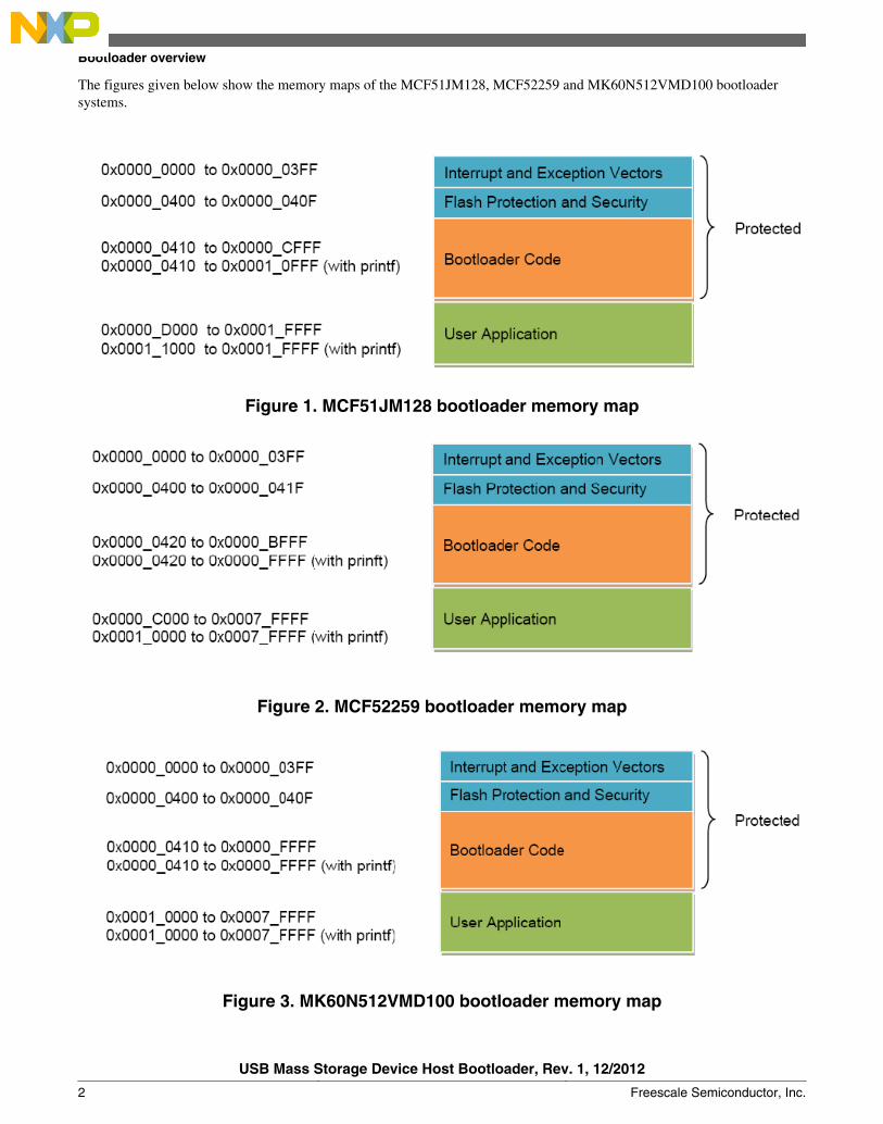
The figures given below show the memory maps of the MCF51JM128, MCF52259 and MK60N512VMD100 bootloadersystems.
Figure 1. MCF51JM128 bootloader memory map
Figure 2. MCF52259 bootloader memory map
Figure 3. MK60N512VMD100 bootloader memory map
Bootloader overview
USB Mass Storage Device Host Bootloader, Rev. 1, 12/2012
2 Freescale Semiconductor, Inc.
The default interrupt and exception vectors are put into the starting address of the flash area and used by the bootloader,which must not be altered. The user application interrupt and exception vectors must be put into the application flash area andcopied to the RAM memory in the application startup routines. The interrupt and exception vectors can be redirected to theRAM area.
The bootloader erases the application flash, parses the user application image and programs it to flash memory of the userapplication area, which is the free flash memory after the bootloader is put into the flash. The code size of the bootloaderbecomes larger when using the printf function to display debug messages. The bootloader flash area has to be protected andthe free flash memory must be block aligned and therefore may become smaller.
For MCF52259, the bootloader without printf support occupies the flash area of 0x0000 to 0x9FFF (40 KB). Since the flashprotecting block size is 16 KB, the flash memory region of 0x0000 to 0xBFFF (48 KB) needs to be protected to preventdamage to the bootloader. After protection, the bootloader occupies 48 KB. The rest of the flash memory from 0xC000 to0x7FFFF (464 KB) is for user application.
The user application can use the whole RAM memory regardless of the size of RAM the bootloader uses.
3 Bootloader architectureThe bootloader includes a bootloader application, a file allocation table (FAT) file system-supporting module, a bootloaderdriver, a flash driver, a USB MSD host class, a USB host stack, and a USB host controller.
The following figure shows the architecture of the bootloader system:
Bootloader architecture
USB Mass Storage Device Host Bootloader, Rev. 1, 12/2012
Freescale Semiconductor, Inc. 3
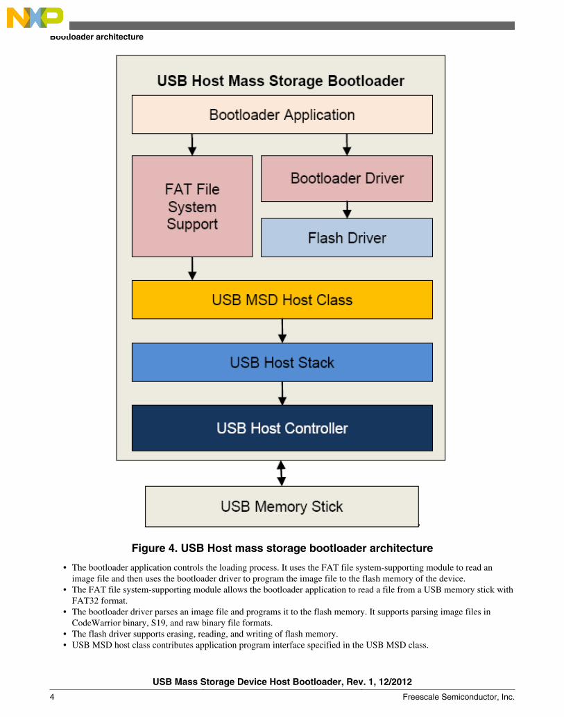
Figure 4. USB Host mass storage bootloader architecture
• The bootloader application controls the loading process. It uses the FAT file system-supporting module to read animage file and then uses the bootloader driver to program the image file to the flash memory of the device.
• The FAT file system-supporting module allows the bootloader application to read a file from a USB memory stick withFAT32 format.
• The bootloader driver parses an image file and programs it to the flash memory. It supports parsing image files inCodeWarrior binary, S19, and raw binary file formats.
• The flash driver supports erasing, reading, and writing of flash memory.• USB MSD host class contributes application program interface specified in the USB MSD class.
Bootloader architecture
USB Mass Storage Device Host Bootloader, Rev. 1, 12/2012
4 Freescale Semiconductor, Inc.
• The USB host stack and the USB host controller communicate with the USB memory stick through the USB MSDprotocols.
• The USB memory stick stores the image file that needs to be programmed to the flash memory. The image file must bein the format of CodeWarrior binary, S19 or raw binary files.
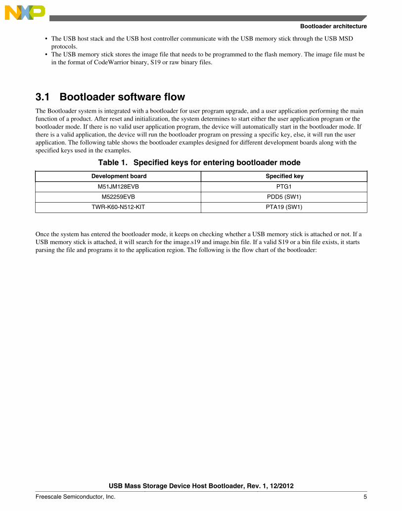
3.1 Bootloader software flowThe Bootloader system is integrated with a bootloader for user program upgrade, and a user application performing the mainfunction of a product. After reset and initialization, the system determines to start either the user application program or thebootloader mode. If there is no valid user application program, the device will automatically start in the bootloader mode. Ifthere is a valid application, the device will run the bootloader program on pressing a specific key, else, it will run the userapplication. The following table shows the bootloader examples designed for different development boards along with thespecified keys used in the examples.
Table 1. Specified keys for entering bootloader mode
Development board Specified key
M51JM128EVB PTG1
M52259EVB PDD5 (SW1)
TWR-K60-N512-KIT PTA19 (SW1)
Once the system has entered the bootloader mode, it keeps on checking whether a USB memory stick is attached or not. If aUSB memory stick is attached, it will search for the image.s19 and image.bin file. If a valid S19 or a bin file exists, it startsparsing the file and programs it to the application region. The following is the flow chart of the bootloader:
Bootloader architecture
USB Mass Storage Device Host Bootloader, Rev. 1, 12/2012
Freescale Semiconductor, Inc. 5
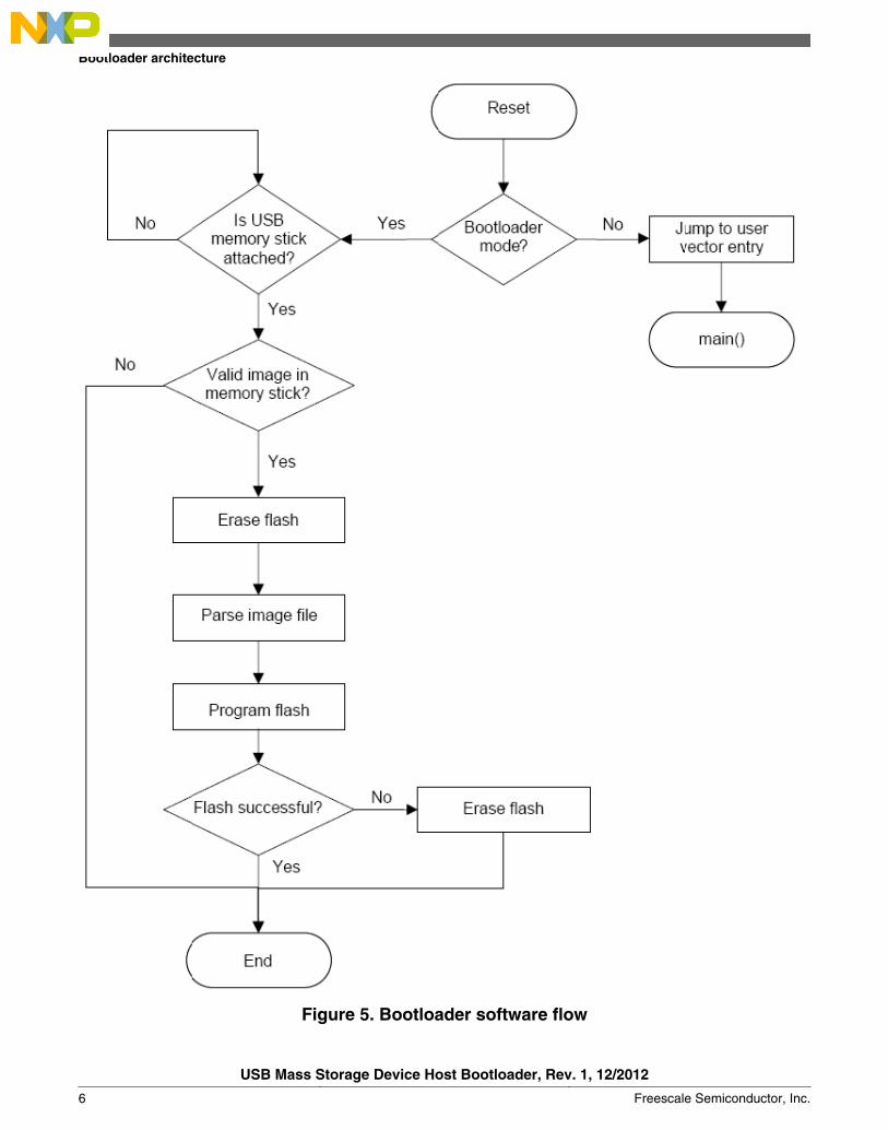
Figure 5. Bootloader software flow
Bootloader architecture
USB Mass Storage Device Host Bootloader, Rev. 1, 12/2012
6 Freescale Semiconductor, Inc.
4 Developing new bootloaderThis section outlines the bootloader file structure and shows how to develop a new bootloader in other platforms.
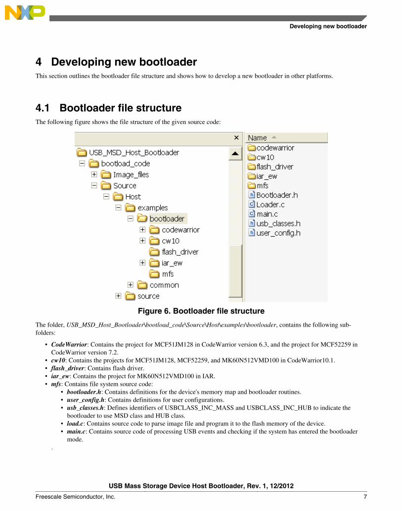
4.1 Bootloader file structureThe following figure shows the file structure of the given source code:
Figure 6. Bootloader file structure
The folder, USB_MSD_Host_Bootloader\bootload_code\Source\Host\examples\bootloader, contains the following sub-folders:
• CodeWarrior: Contains the project for MCF51JM128 in CodeWarrior version 6.3, and the project for MCF52259 inCodeWarrior version 7.2.
• cw10: Contains the projects for MCF51JM128, MCF52259, and MK60N512VMD100 in CodeWarrior10.1.• flash_driver: Contains flash driver.• iar_ew: Contains the project for MK60N512VMD100 in IAR.• mfs: Contains file system source code:
• bootloader.h: Contains definitions for the device's memory map and bootloader routines.• user_config.h: Contains definitions for user configurations.• usb_classes.h: Defines identifiers of USBCLASS_INC_MASS and USBCLASS_INC_HUB to indicate the
bootloader to use MSD class and HUB class.• load.c: Contains source code to parse image file and program it to the flash memory of the device.• main.c: Contains source code of processing USB events and checking if the system has entered the bootloader
mode..
Developing new bootloader
USB Mass Storage Device Host Bootloader, Rev. 1, 12/2012
Freescale Semiconductor, Inc. 7
4.2 Porting bootloader to other platformsThis section describes the steps to port the bootloader to other platforms with the following assumptions:
• The platform supports the USB MSD class.• The platform supports the FAT32 file system.• There is a flash driver.
The following steps can guide the users to port the bootloader to other platforms:
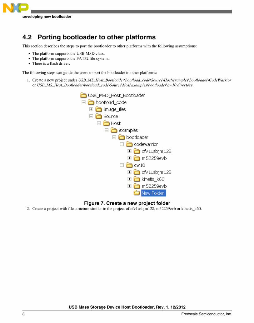
1. Create a new project under USB_MS_Host_Bootloader\bootload_code\Source\Host\examples\bootloader\CodeWarrioror USB_MS_Host_Bootloader\bootload_code\Source\Host\examples\bootloader\cw10 directory.
Figure 7. Create a new project folder2. Create a project with file structure similar to the project of cfv1usbjm128, m52259evb or kinetis_k60.
Developing new bootloader
USB Mass Storage Device Host Bootloader, Rev. 1, 12/2012
8 Freescale Semiconductor, Inc.
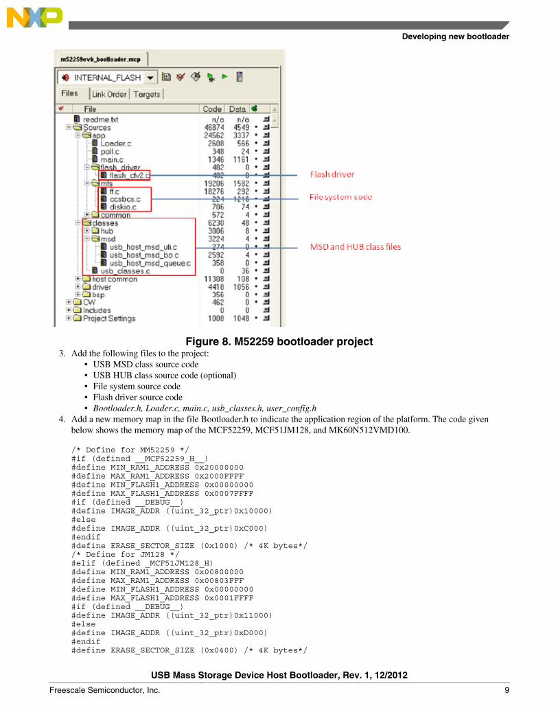
Figure 8. M52259 bootloader project3. Add the following files to the project:
• USB MSD class source code• USB HUB class source code (optional)• File system source code• Flash driver source code• Bootloader.h, Loader.c, main.c, usb_classes.h, user_config.h
4. Add a new memory map in the file Bootloader.h to indicate the application region of the platform. The code givenbelow shows the memory map of the MCF52259, MCF51JM128, and MK60N512VMD100.
/* Define for MM52259 */ #if (defined __MCF52259_H__) #define MIN_RAM1_ADDRESS 0x20000000 #define MAX_RAM1_ADDRESS 0x2000FFFF #define MIN_FLASH1_ADDRESS 0x00000000 #define MAX_FLASH1_ADDRESS 0x0007FFFF #if (defined __DEBUG__) #define IMAGE_ADDR ((uint_32_ptr)0x10000) #else #define IMAGE_ADDR ((uint_32_ptr)0xC000) #endif #define ERASE_SECTOR_SIZE (0x1000) /* 4K bytes*/ /* Define for JM128 */ #elif (defined _MCF51JM128_H) #define MIN_RAM1_ADDRESS 0x00800000 #define MAX_RAM1_ADDRESS 0x00803FFF #define MIN_FLASH1_ADDRESS 0x00000000 #define MAX_FLASH1_ADDRESS 0x0001FFFF #if (defined __DEBUG__) #define IMAGE_ADDR ((uint_32_ptr)0x11000) #else #define IMAGE_ADDR ((uint_32_ptr)0xD000) #endif #define ERASE_SECTOR_SIZE (0x0400) /* 4K bytes*/
Developing new bootloader
USB Mass Storage Device Host Bootloader, Rev. 1, 12/2012
Freescale Semiconductor, Inc. 9
/* Define for K60 */ #elif (defined MCU_MK60N512VMD100) #define MIN_RAM1_ADDRESS 0x1FFF0000 #define MAX_RAM1_ADDRESS 0x20010000 #define MIN_FLASH1_ADDRESS 0x00000000 #define MAX_FLASH1_ADDRESS 0x0007FFFF #define IMAGE_ADDR ((uint_32_ptr)0x10000) #define ERASE_SECTOR_SIZE (0x800) /* 2K bytes*/ #endif
5 Developing new user applicationsThis section describes how normal applications can be modified for the bootloader system.
5.1 Modify linker filesFor normal applications using ColdFire and Kinetis MCUs, the interrupt vector table is located at the beginning of the flasharea and the application code can be put in any of the remaining flash areas. In a bootloader system, the interrupt vector tableand the bootloader program are put into the beginning of flash, and the user application is placed at the remaining flash areas.The linker file must be modified to direct the linker to put the application interrupt vector table and the application code intosome specified memory regions.
Modify CFV1 linker file
The code of a normal application linker file, project.lcf for MCF51JM128, given below, tells the linker that the code can beput in the flash area of 0x410 to 0x1FFFF.
MEMORY { code (RX) : ORIGIN = 0x00000410, LENGTH = 0x0001FBF0 userram (RWX) : ORIGIN = 0x0080000, LENGTH = 0x00004000 }
To work with the bootloader system for MCF51JM128, the user application must be located at the flash memory area startingfrom the address 0xD000 (no printf supported) or 0x11000 (printf supported). The printf supported linker file can bemodified as below:
MEMORY { code (RX) : ORIGIN = 0x00011410, LENGTH = 0x0000EBF0 userram (RWX) : ORIGIN = 0x00800400, LENGTH = 0x00003C00 }
Modify CFV2 linker file
The code of a normal application linker file, MCF52259_INTERNAL_FLASH.lcf for MCF52259, given below, tells thelinker that the code can be put in the flash of 0x420 to 0x7FFFF.
MEMORY { vectorrom (RX) : ORIGIN = 0x00000000, LENGTH = 0x00000400 cfmprotrom (RX) : ORIGIN = 0x00000400, LENGTH = 0x00000020 code (RX) : ORIGIN = 0x00000420, LENGTH = 0x0007FB00 }
To work with the bootloader system for MCF52259, the user application must be located at the flash memory area startingfrom the address 0xC000 (no printf supported) or 0x10000 (printf supported). The printf supported linker file can bemodified as below:
MEMORY { vectorrom (RX) : ORIGIN = 0x00010000, LENGTH = 0x00000400 cfmprotrom (RX) : ORIGIN = 0x00010400, LENGTH = 0x00000020
Developing new user applications
USB Mass Storage Device Host Bootloader, Rev. 1, 12/2012
10 Freescale Semiconductor, Inc.
code (RX) : ORIGIN = 0x00010420, LENGTH = 0x0006FBE0 vectorram (RWX) : ORIGIN = 0x20000000, LENGTH = 0x00000400 }
Modify Kinetis linker file
The code of a normal application linker file, MK60N512VMD100_flash.lcf for MK60N512VMD100, given below, tells thelinker that the code can be put in the flash area of 0x410 to 0x7FFFF.
MEMORY { interrupts (RX) : ORIGIN = 0x00000000, LENGTH = 0x00000400 cfmprotrom (RX) : ORIGIN = 0x00000400, LENGTH = 0x00000010 code (RX) : ORIGIN = 0x00000410, LENGTH = 0x0007FBF0 }
To work with the bootloader system for MK60N512VMD100, the user application must be located at the flash memory areastarting from the address 0x10000 (with or without printf supported). The linker file can be modified as below:
MEMORY { interrupts (RX) : ORIGIN = 0x00010000, LENGTH = 0x00000400 cfmprotrom (RX) : ORIGIN = 0x00010400, LENGTH = 0x0000010 code (RX) : ORIGIN = 0x00010410, LENGTH = 0x0006FBF0 }
5.2 Redirect interrupts and exception vectorsThe default interrupt and exception vectors are put into the starting address of the flash area used by the bootloader, whichmust not be altered. If the user application uses interrupts, the user application interrupt and exception vectors must be putinto the RAM. The ways to redirect and use interrupt vectors in RAM may be different for different MCUs. This sectiondescribes how vector redirection can be done using the Freescale MQX™ USB and other USB stacks.
MQX USB stack
The Freescale MQX USB stack uses the identifier MQX_ROM_VECTORS in the configuration file, userconfig.h, toconfigure applications to put interrupt vectors in RAM or ROM (flash). Users can define MQX_ROM_VECTORS to 0 to putthe interrupt vectors into RAM.
NOTERemember to rebuild the library if the configuration file is changed.
/* userconfig.h */ #define MQX_ROM_VECTORS 0 //DES 1=ROM, 0=RAM vector table...used with bootloaders
Other USB stack
The ways to redirect vector table may be different for different platforms. The following sections describe how to redirectvectors table to RAM for CFV1, CFV2 and Kinetis MCU families.
CFV1 ColdFire
Since the vector table starting from the address 0x0000 is used by the bootloader, the re-directed vector table must be put intoRAM. The vector base register (VBR) of CFV1 ColdFire, for example, MCF51JM128, contains the 1-MB-aligned baseaddress of the exception vector table, which can be used to relocate the vector table from its default position in the flashmemory address 0x0000 to the base address of the RAM, for example 0x0080_0000.
The following code is used to configure the MCU to use vector table at the RAM address 0x0080_0000.
/* startcf.c */ asm (move.l #0x00800000,d0); asm (movec d0,vbr);
Developing new user applications
USB Mass Storage Device Host Bootloader, Rev. 1, 12/2012
Freescale Semiconductor, Inc. 11
The following code is the original code for the linker to put the interrupt routines address into the original flash vector table.
/* exceptions.c */ __declspec(weak) vectorTableEntryType vector_0 @INITSP = (vectorTableEntryType)&_SP_INIT; __declspec(weak) vectorTableEntryType vector_1 @INITPC = (vectorTableEntryType)&_startup; __declspec(weak) vectorTableEntryType vector_2 @Vaccerr = asm_exception_handler;
The application vector table is put into the application flash area and then copied into RAM. The new vector table in thebootloader framework can be declared by the following code:
/* exceptions.c */ #define APP_FLASH 0x00011000; __declspec(weak) vectorTableEntryType vector_0 @(APP_FLASH+INITSP) = (vectorTableEntryType)&_SP_INIT; __declspec(weak) vectorTableEntryType vector_1 @(APP_FLASH+INITPC) = (vectorTableEntryType)&_startup; __declspec(weak) vectorTableEntryType vector_2 @(APP_FLASH+Vaccerr) = asm_exception_handler;}
The following code copies the above vector table from the application flash area to the vector table region in RAM.
/* main.c */ #define APP_FLASH 0x00011000; dword *pdst; dword *psrc; pdst=(dword*)0x00800000; psrc=(dword*)APP_FLASH; for (i=0;i<111;i++){ *pdst++=*psrc++;}
CFV2 microcontrollers
With CFV2 version, for example, MCF52259, Freescale USB Stack with PHDC version 3.0 supports a function to copy theinterrupt vector table to the specified area in RAM. Users working with other stacks can take it as a reference.
void initialize_exceptions(void) { uint32 n; /* Copy the vector table to RAM */ if (__VECTOR_RAM != (unsigned long*)_vect) { for (n = 0; n < 256; n++) __VECTOR_RAM[n] = (unsigned long)_vect[n]; } mcf5xxx_wr_vbr((unsigned long)__VECTOR_RAM); }
The initialize_exceptions function given above copied interrupt vector table to the RAM area at __VECTOR_RAM address.This address (ADDR) needs to be defined at the linker file (*.lcf).
MEMORY {vectorram (RWX) : ORIGIN = 0x20000000, LENGTH = 0x00000400}___VECTOR_RAM = ADDR(.vectorram);
The function given above is called at startup by default so the user program does not need to call this function if using USBStack with PHDC version 3.0.
Kinetis microcontrollers
In Kinetis MCUs, the SCB_VTOR register contains the base address of the exception vector table. To redirect vector table,copy the vector table to RAM and set the SCB_VTOR to the RAM address. Most of the released example codes haveimplemented vector redirection.
The following steps describe the way to redirect vector table for Kinetis MCUs:
1. In the linker file, declare a ROM area to store the vector table and a RAM area for the vector table to copy to.
Developing new user applications
USB Mass Storage Device Host Bootloader, Rev. 1, 12/2012
12 Freescale Semiconductor, Inc.
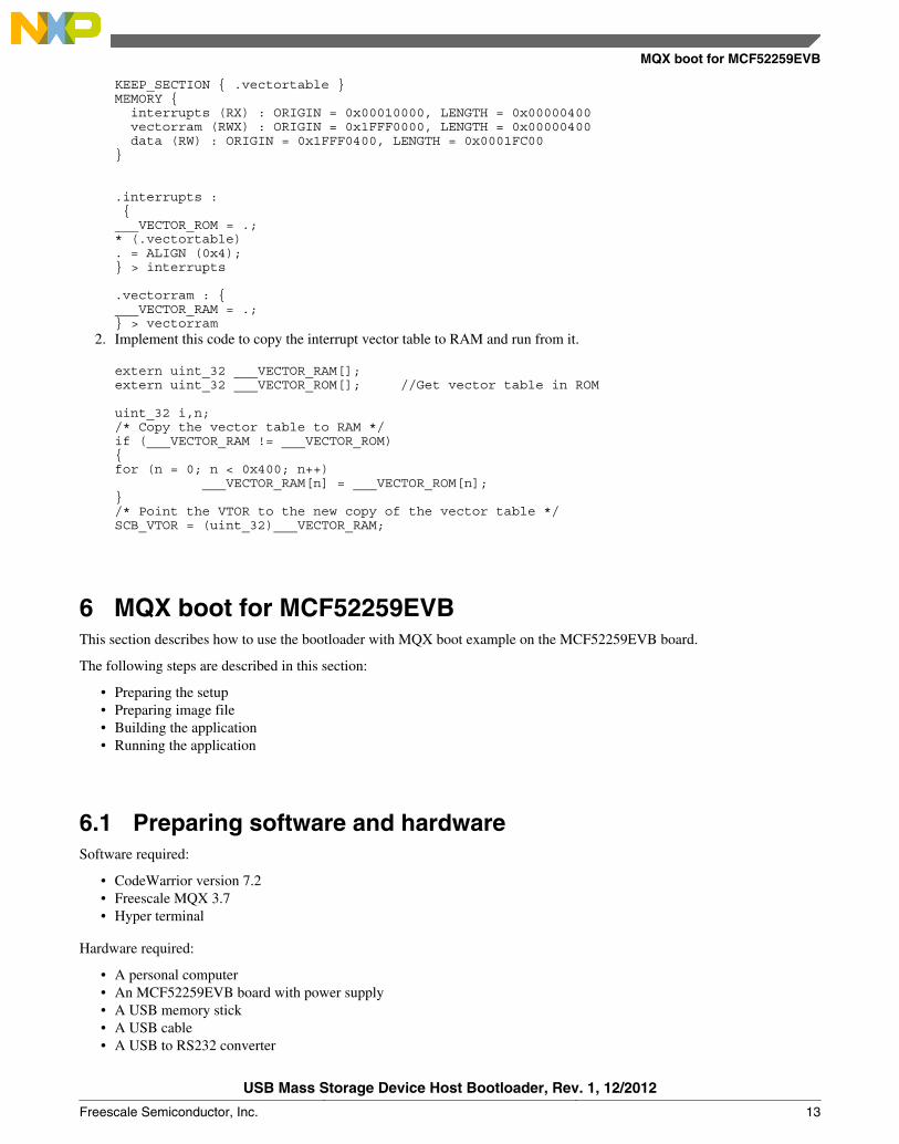
KEEP_SECTION { .vectortable } MEMORY { interrupts (RX) : ORIGIN = 0x00010000, LENGTH = 0x00000400 vectorram (RWX) : ORIGIN = 0x1FFF0000, LENGTH = 0x00000400 data (RW) : ORIGIN = 0x1FFF0400, LENGTH = 0x0001FC00 }
.interrupts : { ___VECTOR_ROM = .; * (.vectortable) . = ALIGN (0x4); } > interrupts
.vectorram : { ___VECTOR_RAM = .; } > vectorram
2. Implement this code to copy the interrupt vector table to RAM and run from it.
extern uint_32 ___VECTOR_RAM[]; extern uint_32 ___VECTOR_ROM[]; //Get vector table in ROM
uint_32 i,n; /* Copy the vector table to RAM */ if (___VECTOR_RAM != ___VECTOR_ROM) { for (n = 0; n < 0x400; n++) ___VECTOR_RAM[n] = ___VECTOR_ROM[n]; } /* Point the VTOR to the new copy of the vector table */ SCB_VTOR = (uint_32)___VECTOR_RAM;
6 MQX boot for MCF52259EVBThis section describes how to use the bootloader with MQX boot example on the MCF52259EVB board.
The following steps are described in this section:
• Preparing the setup• Preparing image file• Building the application• Running the application
6.1 Preparing software and hardwareSoftware required:
• CodeWarrior version 7.2• Freescale MQX 3.7• Hyper terminal
Hardware required:
• A personal computer• An MCF52259EVB board with power supply• A USB memory stick• A USB cable• A USB to RS232 converter
MQX boot for MCF52259EVB
USB Mass Storage Device Host Bootloader, Rev. 1, 12/2012
Freescale Semiconductor, Inc. 13
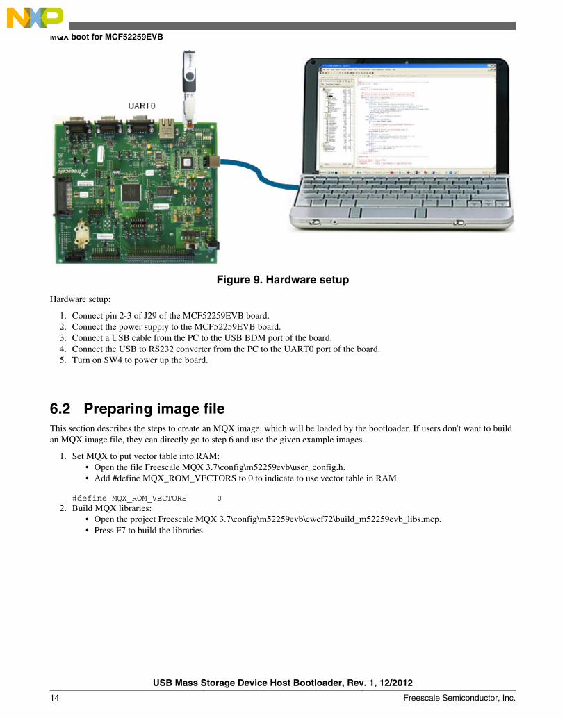
Figure 9. Hardware setup
Hardware setup:
1. Connect pin 2-3 of J29 of the MCF52259EVB board.2. Connect the power supply to the MCF52259EVB board.3. Connect a USB cable from the PC to the USB BDM port of the board.4. Connect the USB to RS232 converter from the PC to the UART0 port of the board.5. Turn on SW4 to power up the board.
6.2 Preparing image fileThis section describes the steps to create an MQX image, which will be loaded by the bootloader. If users don't want to buildan MQX image file, they can directly go to step 6 and use the given example images.
1. Set MQX to put vector table into RAM:• Open the file Freescale MQX 3.7\config\m52259evb\user_config.h.• Add #define MQX_ROM_VECTORS to 0 to indicate to use vector table in RAM.
#define MQX_ROM_VECTORS 02. Build MQX libraries:
• Open the project Freescale MQX 3.7\config\m52259evb\cwcf72\build_m52259evb_libs.mcp.• Press F7 to build the libraries.
MQX boot for MCF52259EVB
USB Mass Storage Device Host Bootloader, Rev. 1, 12/2012
14 Freescale Semiconductor, Inc.
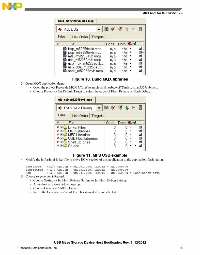
Figure 10. Build MQX libraries3. Open MQX application demo:
• Open the project Freescale MQX 3.7\mfs\examples\mfs_usb\cwcf72\mfs_usb_m5329evb.mcp.• Choose Project -> Set Default Target to select the target of Flash Release or Flash Debug.
Figure 11. MFS USB example4. Modify the intflash.lcf linker file to move ROM section of this application to the application flash region.
vectorrom (RX): ORIGIN = 0x00010000, LENGTH = 0x00000400cfmprotrom (RX): ORIGIN = 0x00010400, LENGTH = 0x00000020rom (RX): ORIGIN = 0x00010420, LENGTH = 0x0006FBE0 # Code+Const data
5. Choose to generate S-Record:• Choose Setting -> Int Flash Release Setting or Int Flash Debug Setting.• A window as shown below pops up.• Choose Linker-> ColdFire Linker.• Select the Generate S-Record File checkbox if it is not selected.
MQX boot for MCF52259EVB
USB Mass Storage Device Host Bootloader, Rev. 1, 12/2012
Freescale Semiconductor, Inc. 15
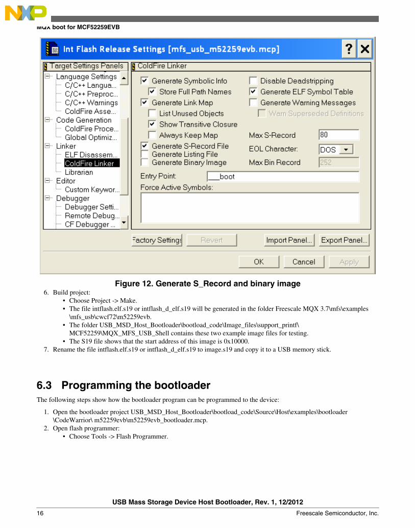
Figure 12. Generate S_Record and binary image6. Build project:
• Choose Project -> Make.• The file intflash.elf.s19 or intflash_d_elf.s19 will be generated in the folder Freescale MQX 3.7\mfs\examples
\mfs_usb\cwcf72\m52259evb.• The folder USB_MSD_Host_Bootloader\bootload_code\Image_files\support_printf\
MCF52259\MQX_MFS_USB_Shell contains these two example image files for testing.• The S19 file shows that the start address of this image is 0x10000.
7. Rename the file intflash.elf.s19 or intflash_d_elf.s19 to image.s19 and copy it to a USB memory stick.
6.3 Programming the bootloaderThe following steps show how the bootloader program can be programmed to the device:
1. Open the bootloader project USB_MSD_Host_Bootloader\bootload_code\Source\Host\examples\bootloader\CodeWarrior\ m52259evb\m52259evb_bootloader.mcp.
2. Open flash programmer:• Choose Tools -> Flash Programmer.
MQX boot for MCF52259EVB
USB Mass Storage Device Host Bootloader, Rev. 1, 12/2012
16 Freescale Semiconductor, Inc.
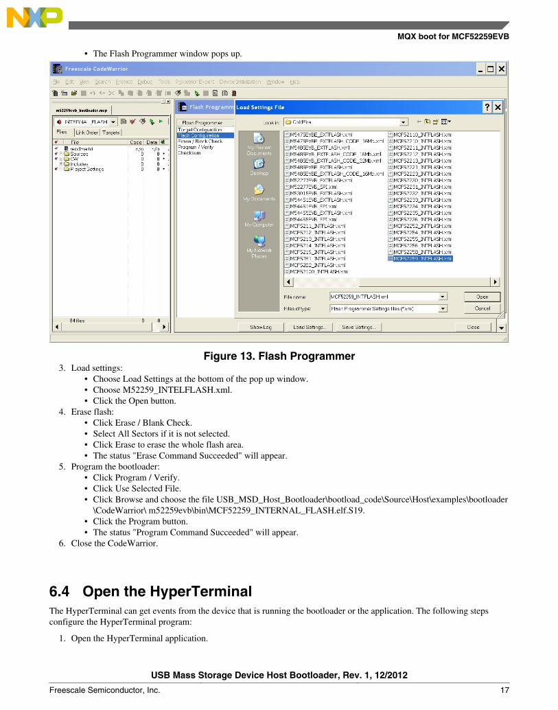
• The Flash Programmer window pops up.•
Figure 13. Flash Programmer3. Load settings:
• Choose Load Settings at the bottom of the pop up window.• Choose M52259_INTELFLASH.xml.• Click the Open button.
4. Erase flash:• Click Erase / Blank Check.• Select All Sectors if it is not selected.• Click Erase to erase the whole flash area.• The status "Erase Command Succeeded" will appear.
5. Program the bootloader:• Click Program / Verify.• Click Use Selected File.• Click Browse and choose the file USB_MSD_Host_Bootloader\bootload_code\Source\Host\examples\bootloader
\CodeWarrior\ m52259evb\bin\MCF52259_INTERNAL_FLASH.elf.S19.• Click the Program button.• The status "Program Command Succeeded" will appear.
6. Close the CodeWarrior.
6.4 Open the HyperTerminalThe HyperTerminal can get events from the device that is running the bootloader or the application. The following stepsconfigure the HyperTerminal program:
1. Open the HyperTerminal application.
MQX boot for MCF52259EVB
USB Mass Storage Device Host Bootloader, Rev. 1, 12/2012
Freescale Semiconductor, Inc. 17
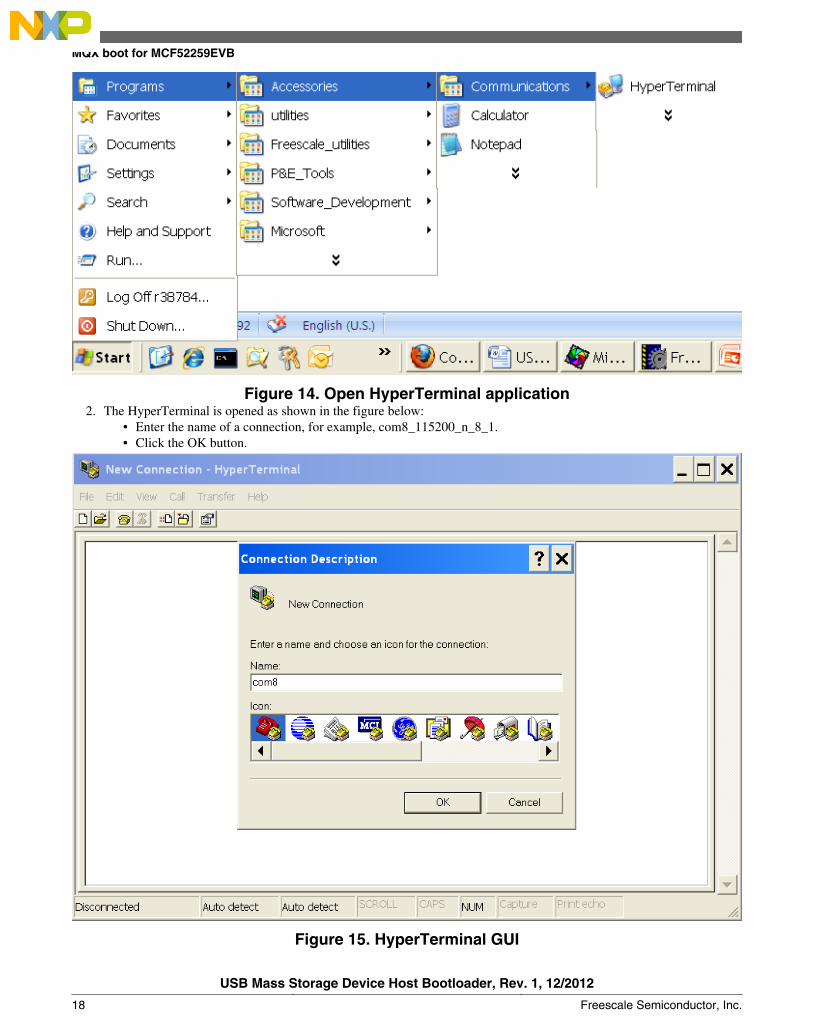
Figure 14. Open HyperTerminal application2. The HyperTerminal is opened as shown in the figure below:
• Enter the name of a connection, for example, com8_115200_n_8_1.• Click the OK button.•
Figure 15. HyperTerminal GUI
MQX boot for MCF52259EVB
USB Mass Storage Device Host Bootloader, Rev. 1, 12/2012
18 Freescale Semiconductor, Inc.
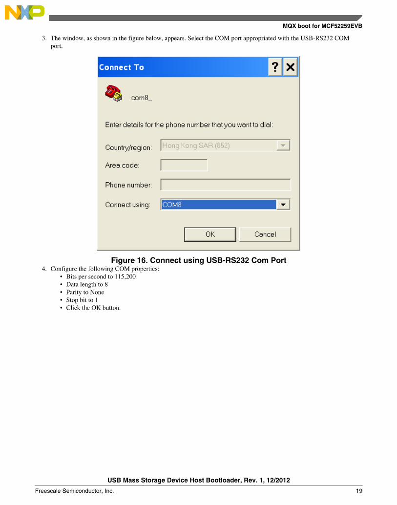
3. The window, as shown in the figure below, appears. Select the COM port appropriated with the USB-RS232 COMport.
Figure 16. Connect using USB-RS232 Com Port4. Configure the following COM properties:
• Bits per second to 115,200• Data length to 8• Parity to None• Stop bit to 1• Click the OK button.
MQX boot for MCF52259EVB
USB Mass Storage Device Host Bootloader, Rev. 1, 12/2012
Freescale Semiconductor, Inc. 19
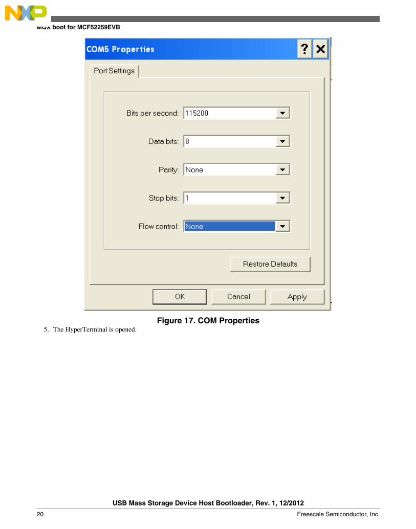
Figure 17. COM Properties5. The HyperTerminal is opened.
MQX boot for MCF52259EVB
USB Mass Storage Device Host Bootloader, Rev. 1, 12/2012
20 Freescale Semiconductor, Inc.
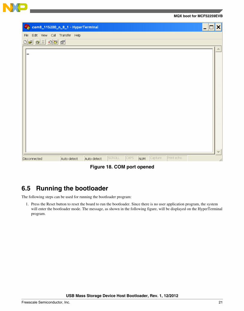
Figure 18. COM port opened
6.5 Running the bootloaderThe following steps can be used for running the bootloader program:
1. Press the Reset button to reset the board to run the bootloader. Since there is no user application program, the systemwill enter the bootloader mode. The message, as shown in the following figure, will be displayed on the HyperTerminalprogram.
MQX boot for MCF52259EVB
USB Mass Storage Device Host Bootloader, Rev. 1, 12/2012
Freescale Semiconductor, Inc. 21
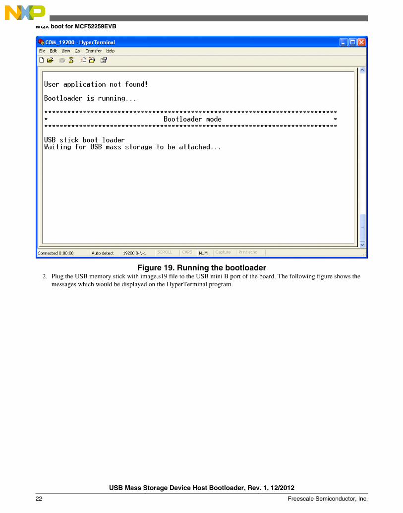
Figure 19. Running the bootloader2. Plug the USB memory stick with image.s19 file to the USB mini B port of the board. The following figure shows the
messages which would be displayed on the HyperTerminal program.
MQX boot for MCF52259EVB
USB Mass Storage Device Host Bootloader, Rev. 1, 12/2012
22 Freescale Semiconductor, Inc.
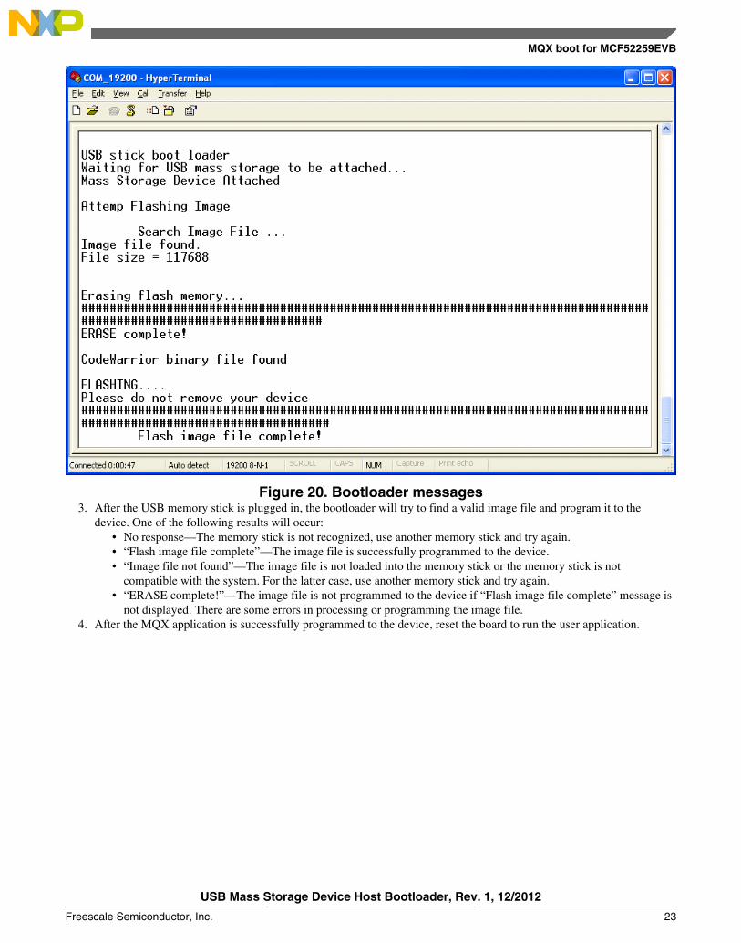
Figure 20. Bootloader messages3. After the USB memory stick is plugged in, the bootloader will try to find a valid image file and program it to the
device. One of the following results will occur:• No response—The memory stick is not recognized, use another memory stick and try again.• “Flash image file complete”—The image file is successfully programmed to the device.• “Image file not found”—The image file is not loaded into the memory stick or the memory stick is not
compatible with the system. For the latter case, use another memory stick and try again.• “ERASE complete!”—The image file is not programmed to the device if “Flash image file complete” message is
not displayed. There are some errors in processing or programming the image file.4. After the MQX application is successfully programmed to the device, reset the board to run the user application.
MQX boot for MCF52259EVB
USB Mass Storage Device Host Bootloader, Rev. 1, 12/2012
Freescale Semiconductor, Inc. 23
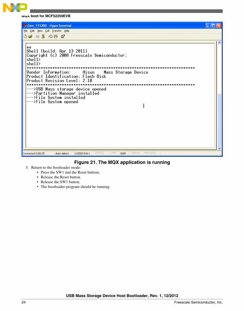
Figure 21. The MQX application is running5. Return to the bootloader mode:
• Press the SW1 and the Reset buttons.• Release the Reset button.• Release the SW1 button.• The bootloader program should be running.
MQX boot for MCF52259EVB
USB Mass Storage Device Host Bootloader, Rev. 1, 12/2012
24 Freescale Semiconductor, Inc.
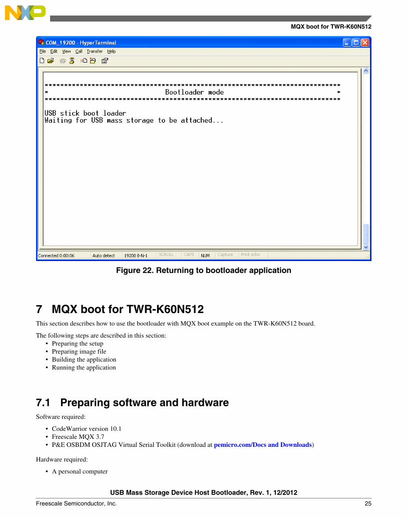
Figure 22. Returning to bootloader application
7 MQX boot for TWR-K60N512This section describes how to use the bootloader with MQX boot example on the TWR-K60N512 board.
The following steps are described in this section:• Preparing the setup• Preparing image file• Building the application• Running the application
7.1 Preparing software and hardwareSoftware required:
• CodeWarrior version 10.1• Freescale MQX 3.7• P&E OSBDM OSJTAG Virtual Serial Toolkit (download at pemicro.com/Docs and Downloads)
Hardware required:
• A personal computer
MQX boot for TWR-K60N512
USB Mass Storage Device Host Bootloader, Rev. 1, 12/2012
Freescale Semiconductor, Inc. 25
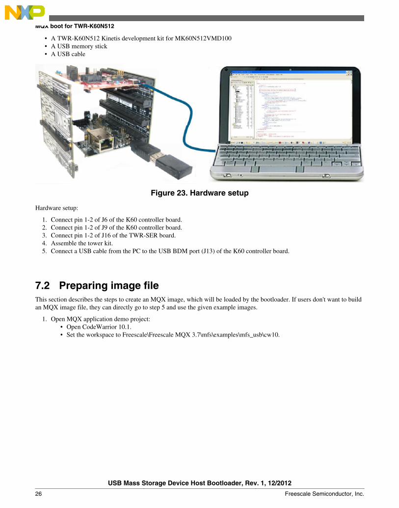
• A TWR-K60N512 Kinetis development kit for MK60N512VMD100• A USB memory stick• A USB cable
Figure 23. Hardware setup
Hardware setup:
1. Connect pin 1-2 of J6 of the K60 controller board.2. Connect pin 1-2 of J9 of the K60 controller board.3. Connect pin 1-2 of J16 of the TWR-SER board.4. Assemble the tower kit.5. Connect a USB cable from the PC to the USB BDM port (J13) of the K60 controller board.
7.2 Preparing image fileThis section describes the steps to create an MQX image, which will be loaded by the bootloader. If users don't want to buildan MQX image file, they can directly go to step 5 and use the given example images.
1. Open MQX application demo project:• Open CodeWarrior 10.1.• Set the workspace to Freescale\Freescale MQX 3.7\mfs\examples\mfs_usb\cw10.
MQX boot for TWR-K60N512
USB Mass Storage Device Host Bootloader, Rev. 1, 12/2012
26 Freescale Semiconductor, Inc.
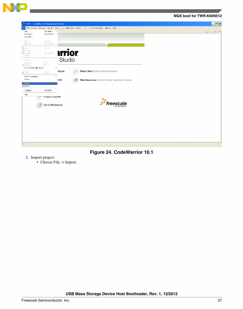
Figure 24. CodeWarrior 10.12. Import project:
• Choose File -> Import.
MQX boot for TWR-K60N512
USB Mass Storage Device Host Bootloader, Rev. 1, 12/2012
Freescale Semiconductor, Inc. 27
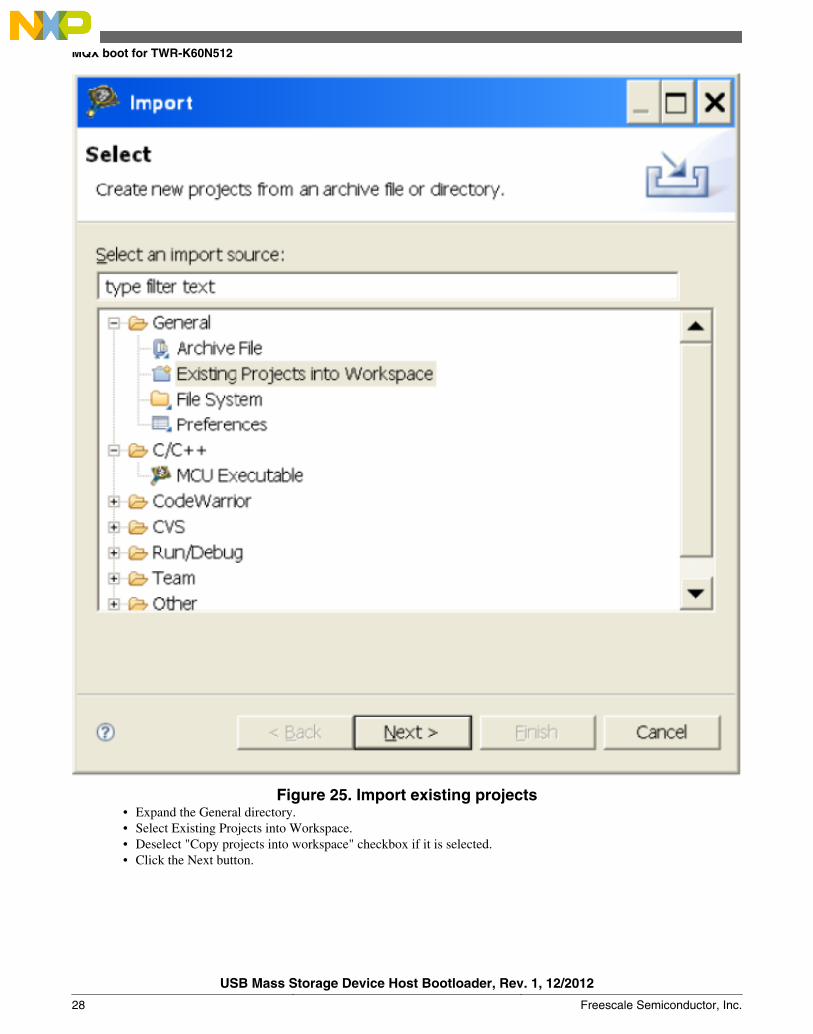
Figure 25. Import existing projects• Expand the General directory.• Select Existing Projects into Workspace.• Deselect "Copy projects into workspace" checkbox if it is selected.• Click the Next button.
MQX boot for TWR-K60N512
USB Mass Storage Device Host Bootloader, Rev. 1, 12/2012
28 Freescale Semiconductor, Inc.
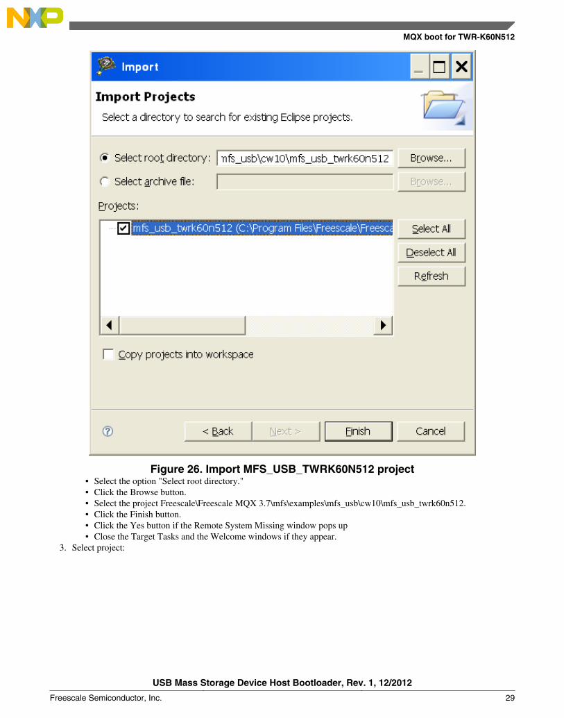
Figure 26. Import MFS_USB_TWRK60N512 project• Select the option "Select root directory."• Click the Browse button.• Select the project Freescale\Freescale MQX 3.7\mfs\examples\mfs_usb\cw10\mfs_usb_twrk60n512.• Click the Finish button.• Click the Yes button if the Remote System Missing window pops up• Close the Target Tasks and the Welcome windows if they appear.
3. Select project:
MQX boot for TWR-K60N512
USB Mass Storage Device Host Bootloader, Rev. 1, 12/2012
Freescale Semiconductor, Inc. 29
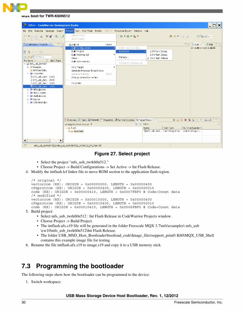
Figure 27. Select project
• Select the project "mfs_usb_twrk60n512."• Choose Project -> Build Configurations -> Set Active -> Int Flash Release.
4. Modify the intflash.lcf linker file to move ROM section to the application flash region.
/* original */vectorrom (RX): ORIGIN = 0x00000000, LENGTH = 0x00000400cfmprotrom (RX): ORIGIN = 0x00000400, LENGTH = 0x00000010code (RX): ORIGIN = 0x00000410, LENGTH = 0x0007FBF0 # Code+Const data/* modified */vectorrom (RX): ORIGIN = 0x00010000, LENGTH = 0x00000400cfmprotrom (RX): ORIGIN = 0x00010400, LENGTH = 0x00000010code (RX): ORIGIN = 0x00010410, LENGTH = 0x0006FBF0 # Code+Const data
5. Build project:• Select mfs_usb_twrk60n512 : Int Flash Release in CodeWarrior Projects window.• Choose Project -> Build Project.• The intflash.afx.s19 file will be generated in the folder Freescale MQX 3.7\mfs\examples\ mfs_usb
\cw10\mfs_usb_twrk60n512\Int Flash Release.• The folder USB_MSD_Host_Bootloader\bootload_code\Image_files\support_printf\ K60\MQX_USB_Shell
contains this example image file for testing.6. Rename the file intflash.afx.s19 to image.s19 and copy it to a USB memory stick.
7.3 Programming the bootloaderThe following steps show how the bootloader can be programmed to the device:
1. Switch workspace:
MQX boot for TWR-K60N512
USB Mass Storage Device Host Bootloader, Rev. 1, 12/2012
30 Freescale Semiconductor, Inc.
• Choose File -> Switch Workspace and select the directory USB_MSD_Host_Bootloader\bootload_code\Source\Host\examples\bootloader\cw10.
2. Import project:• Choose File -> Import.• Expand the General directory.• Select "Existing Projects into workspace."• Click the Next button.• Select the option "Select root directory."• Click the Browse button.• Select the project USB_MSD_Host_Bootloader\bootload_code\Source\Host\examples\bootloader\cw10\
kinetis_k60.• Click the Finish button.• Click the Yes button if the Remote System Missing window pops up.• Close the Target Tasks and the Welcome windows if they appear.
3. Select project:• Select the project "kinetis_k60," in the CodeWarrior Projects window.• Choose Project -> Build Configurations -> Set Active -> MK60N512VMD100_INTERNAL_FLASH.
4. Build project:• Choose Project -> Build Project.
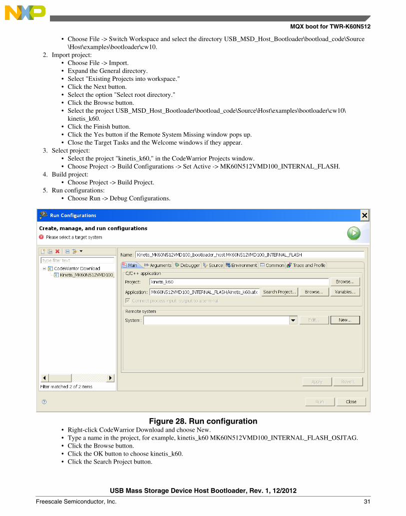
5. Run configurations:• Choose Run -> Debug Configurations.
Figure 28. Run configuration• Right-click CodeWarrior Download and choose New.• Type a name in the project, for example, kinetis_k60 MK60N512VMD100_INTERNAL_FLASH_OSJTAG.• Click the Browse button.• Click the OK button to choose kinetis_k60.• Click the Search Project button.
MQX boot for TWR-K60N512
USB Mass Storage Device Host Bootloader, Rev. 1, 12/2012
Freescale Semiconductor, Inc. 31
• Click the OK button to choose kinetis_k60_afx application.• Click the New button to open the new connection.
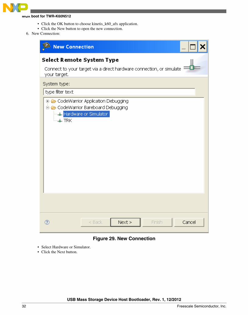
6. New Connection:
Figure 29. New Connection
• Select Hardware or Simulator.• Click the Next button.
MQX boot for TWR-K60N512
USB Mass Storage Device Host Bootloader, Rev. 1, 12/2012
32 Freescale Semiconductor, Inc.
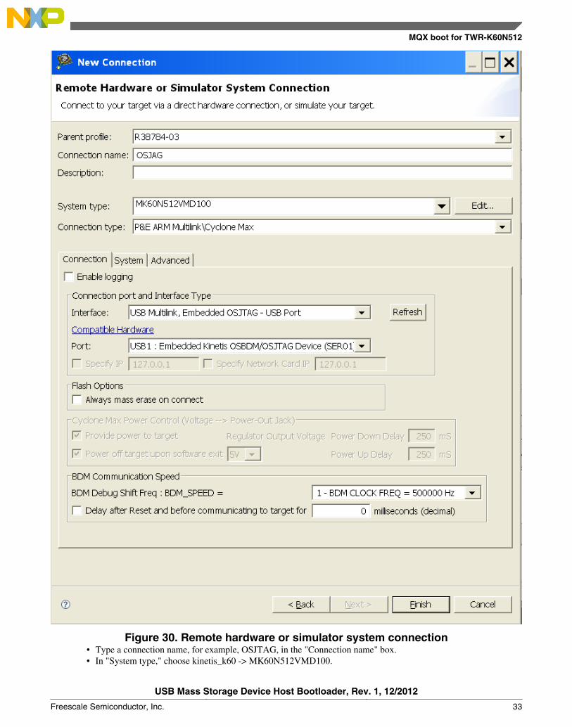
Figure 30. Remote hardware or simulator system connection• Type a connection name, for example, OSJTAG, in the "Connection name" box.• In "System type," choose kinetis_k60 -> MK60N512VMD100.
MQX boot for TWR-K60N512
USB Mass Storage Device Host Bootloader, Rev. 1, 12/2012
Freescale Semiconductor, Inc. 33
• In "Connection type," select P&E ARM Multilink\Cyclone Max.• Click the Finish button.
7. Program the bootloader:• Click the Debug button to program the bootloader to the device.
8. Close the CodeWarrior.
7.4 Opening the virtual terminalThe P&E OSBDM OSJTAG Terminal Utility can get events from the device that is running the bootloader or the application.For TWR-K60N512 tower board, the communication is through UART5 of K60 and the USB OSBDM.
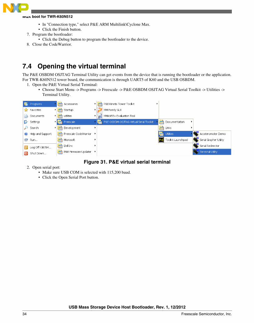
1. Open the P&E Virtual Serial Terminal:• Choose Start Menu -> Programs -> Freescale -> P&E OSBDM OSJTAG Virtual Serial Toolkit -> Utilities ->
Terminal Utility.
Figure 31. P&E virtual serial terminal2. Open serial port:
• Make sure USB COM is selected with 115,200 baud.• Click the Open Serial Port button.
MQX boot for TWR-K60N512
USB Mass Storage Device Host Bootloader, Rev. 1, 12/2012
34 Freescale Semiconductor, Inc.
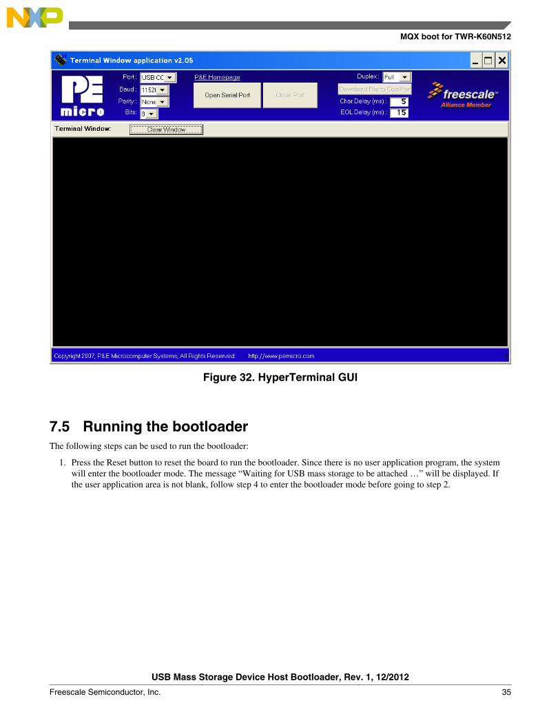
Figure 32. HyperTerminal GUI
7.5 Running the bootloaderThe following steps can be used to run the bootloader:
1. Press the Reset button to reset the board to run the bootloader. Since there is no user application program, the systemwill enter the bootloader mode. The message “Waiting for USB mass storage to be attached …” will be displayed. Ifthe user application area is not blank, follow step 4 to enter the bootloader mode before going to step 2.
MQX boot for TWR-K60N512
USB Mass Storage Device Host Bootloader, Rev. 1, 12/2012
Freescale Semiconductor, Inc. 35
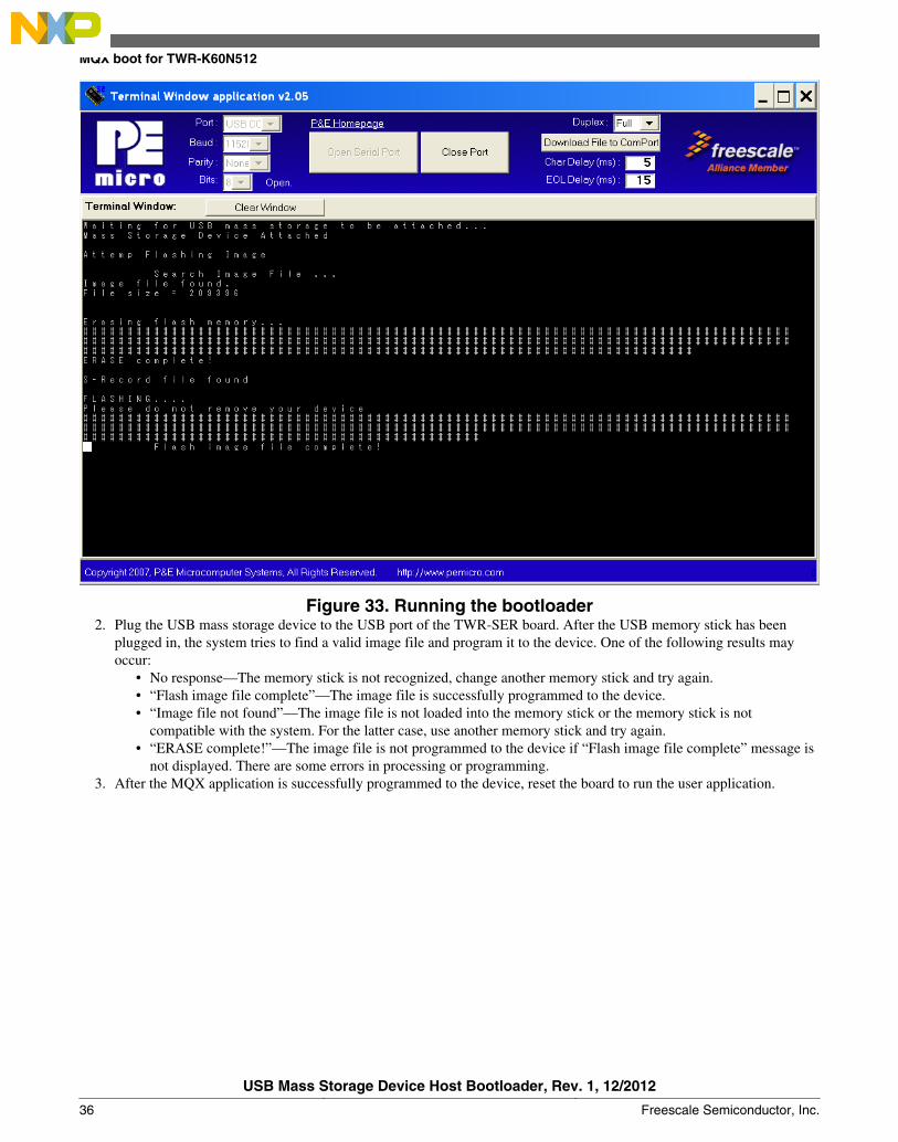
Figure 33. Running the bootloader2. Plug the USB mass storage device to the USB port of the TWR-SER board. After the USB memory stick has been
plugged in, the system tries to find a valid image file and program it to the device. One of the following results mayoccur:
• No response—The memory stick is not recognized, change another memory stick and try again.• “Flash image file complete”—The image file is successfully programmed to the device.• “Image file not found”—The image file is not loaded into the memory stick or the memory stick is not
compatible with the system. For the latter case, use another memory stick and try again.• “ERASE complete!”—The image file is not programmed to the device if “Flash image file complete” message is
not displayed. There are some errors in processing or programming.3. After the MQX application is successfully programmed to the device, reset the board to run the user application.
MQX boot for TWR-K60N512
USB Mass Storage Device Host Bootloader, Rev. 1, 12/2012
36 Freescale Semiconductor, Inc.
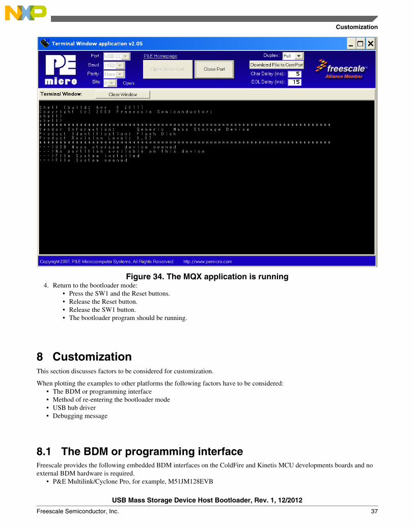
Figure 34. The MQX application is running4. Return to the bootloader mode:
• Press the SW1 and the Reset buttons.• Release the Reset button.• Release the SW1 button.• The bootloader program should be running.
8 CustomizationThis section discusses factors to be considered for customization.
When plotting the examples to other platforms the following factors have to be considered:• The BDM or programming interface• Method of re-entering the bootloader mode• USB hub driver• Debugging message
8.1 The BDM or programming interfaceFreescale provides the following embedded BDM interfaces on the ColdFire and Kinetis MCU developments boards and noexternal BDM hardware is required.
• P&E Multilink/Cyclone Pro, for example, M51JM128EVB
Customization
USB Mass Storage Device Host Bootloader, Rev. 1, 12/2012
Freescale Semiconductor, Inc. 37
• CFV1 Open Source BDM, for example, TWR-MCF51MM• PEMICRO_USB, for example, M52259EVB• ColdFire v2-v4 JM60 OSBDM, for example, TWR-MCF5225X• USB Multilink, Embedded OSJTAG – USB Port, for example, TWR-K60N512
While using different BDM interfaces, users have to set the corresponding BDM interface correctly. All embedded BDMs,except the PEMICRO_USB, provide virtual COM interface.
8.2 Method of re-entering bootloader modeIn our demos, pressing SW1 during power-up forces the system to enter the bootloader mode. Users can modify theSwitch_mode function in the main.c file to choose other input pins or other methods to enter the bootloader mode.
8.3 USB hub driverUsers may choose to remove the USB hub driver and reduce the bootloader code size if it is not necessary to support hubfunctions in the bootloader system. This can be done by undefining the identifier of USBCLASS_INC_HUB in theusb_classes.h file.
8.4 Debugging messageThe debugging message can be displayed through the UART ports of the MCUs. Users can choose their methods ofbootloader communications with the end users. For example, LEDs can be used to indicate the bootloader status and disablethe debugging message and hence reduce the bootloader code size. The debugging message can be disabled by undefining the_DEBUG_ identifier in the derivative.h file.
9 ConclusionExample codes of USB MSD class bootloader have been built for Freescale 32-bit ColdFire and Kinetis MCU families. Userapplication codes can be programmed to the MCUs by plugging a USB memory stick into the system.
Users can plot the example codes to other Freescale MCUs and customize the codes for their own applications.
Conclusion
USB Mass Storage Device Host Bootloader, Rev. 1, 12/2012
38 Freescale Semiconductor, Inc.
How to Reach Us:
Home Page:www.freescale.com
Web Support:http://www.freescale.com/support
USA/Europe or Locations Not Listed:Freescale SemiconductorTechnical Information Center, EL5162100 East Elliot RoadTempe, Arizona 85284+1-800-521-6274 or +1-480-768-2130www.freescale.com/support
Europe, Middle East, and Africa:Freescale Halbleiter Deutschland GmbHTechnical Information CenterSchatzbogen 781829 Muenchen, Germany+44 1296 380 456 (English)+46 8 52200080 (English)+49 89 92103 559 (German)+33 1 69 35 48 48 (French)www.freescale.com/support
Japan:Freescale Semiconductor Japan Ltd.HeadquartersARCO Tower 15F1-8-1, Shimo-Meguro, Meguro-ku,Tokyo 153-0064Japan0120 191014 or +81 3 5437 [email protected]
Asia/Pacific:Freescale Semiconductor China Ltd.Exchange Building 23FNo. 118 Jianguo RoadChaoyang DistrictBeijing 100022China+86 10 5879 [email protected]
Document Number: AN4368Rev. 1, 12/2012
Information in this document is provided solely to enable system and softwareimplementers to use Freescale Semiconductors products. There are no express or impliedcopyright licenses granted hereunder to design or fabricate any integrated circuits orintegrated circuits based on the information in this document.
Freescale Semiconductor reserves the right to make changes without further notice to anyproducts herein. Freescale Semiconductor makes no warranty, representation, orguarantee regarding the suitability of its products for any particular purpose, nor doesFreescale Semiconductor assume any liability arising out of the application or use of anyproduct or circuit, and specifically disclaims any liability, including without limitationconsequential or incidental damages. "Typical" parameters that may be provided inFreescale Semiconductor data sheets and/or specifications can and do vary in differentapplications and actual performance may vary over time. All operating parameters,including "Typicals", must be validated for each customer application by customer'stechnical experts. Freescale Semiconductor does not convey any license under its patentrights nor the rights of others. Freescale Semiconductor products are not designed,intended, or authorized for use as components in systems intended for surgical implantinto the body, or other applications intended to support or sustain life, or for any otherapplication in which failure of the Freescale Semiconductor product could create asituation where personal injury or death may occur. Should Buyer purchase or useFreescale Semiconductor products for any such unintended or unauthorized application,Buyer shall indemnify Freescale Semiconductor and its officers, employees, subsidiaries,affiliates, and distributors harmless against all claims, costs, damages, and expenses, andreasonable attorney fees arising out of, directly or indirectly, any claim of personal injuryor death associated with such unintended or unauthorized use, even if such claims allegesthat Freescale Semiconductor was negligent regarding the design or manufacture ofthe part.
RoHS-compliant and/or Pb-free versions of Freescale products have the functionality andelectrical characteristics as their non-RoHS-complaint and/or non-Pb-free counterparts.For further information, see http://www.freescale.com or contact your Freescalesales representative.
For information on Freescale's Environmental Products program, go tohttp://www.freescale.com/epp.
Freescale™ and the Freescale logo are trademarks of Freescale Semiconductor, Inc.All other product or service names are the property of their respective owners.
© 2011 Freescale Semiconductor, Inc.


![SAM D21 XPRO USB Host MSC Bootloader · SAM D21 XPRO USB Host MSC Bootloader [TRAINING MANUAL] Atmel-42352A-SAM-D21-XPRO-USB-Host-MSC-Bootloader_Training-Manual_022015 4 1 Training](https://static.fdocuments.net/doc/165x107/5f0556927e708231d41278b3/sam-d21-xpro-usb-host-msc-bootloader-sam-d21-xpro-usb-host-msc-bootloader-training.jpg)