US000009278453B220160308 - NASA · active subset of the EMG sensors are identified to sense the...
16
11111111111111111111111111111111111111111111111111111111111111111111111111 (12) United States Patent Assad (54) BIOSLEEVE HUMAN-MACHINE INTERFACE (71) Applicant: Christopher Assad, Long Beach, CA (US) (72) Inventor: Christopher Assad, Long Beach, CA (US) (73) Assignee: California Institute of Technology, Pasadena, CA (US) (*) Notice: Subject to any disclaimer, the term of this patent is extended or adjusted under 35 U.S.C. 154(b) by 94 days. (21) Appl. No.: 13/903,781 (22) Filed: May 28, 2013 (65) Prior Publication Data US 2013/0317648 Al Nov. 28, 2013 Related U.S. Application Data (60) Provisional application No. 61/651,728, filed on May 25, 2012. (51) Int. Cl. B25J 9116 (2006.01) G06F 3101 (2006.01) B25J 9110 (2006.01) A61B 510488 (2006.01) A61B 5100 (2006.01) A61B 5111 (2006.01) G06K9100 (2006.01) (52) U.S. Cl. CPC ........... B25J 911694 (2013.01); A61B 5104888 (2013.01); B25J 91104 (2013.01); G06F 31011 (2013.01); G06F 31014 (2013.01); A61B 511116 (2013.01); A61B 511122 (2013.01); A61B 516825 (2013.01); A61B 516826 (2013.01); A61B 516831 (2013.01); A61B 51721 (2013.01); A61B 517267 (2013.01); G05B 2219136435 (2013.01); G06K 9100355 (2013.01) (1o) Patent No.: US 9,278,453 B2 (45) Date of Patent: Mar. 8, 2016 (58) Field of Classification Search CPC .......... B25J 9/1694; G06F 3/01; G06F 3/011; G06F 3/014; G06F 3/015; G06F 3/017; A61B 5/721; A61B 5/04888; A61B 5/0488 See application file for complete search history. (56) References Cited U.S. PATENT DOCUMENTS 2009/0326406 At * 12/2009 Tan et al . ...................... 600/546 2011/0264238 At * 10/2011 van der Merwe et al. ...... 623/24 OTHER PUBLICATIONS Xu Zhang; Xiang Chen; Yun Li; Lantz, V.; Kongqiao Wang; Jihai Yang, "A Framework for Hand Gesture Recognition Based on Accel- erometer and EMG Sensors," Systems, Man and Cybernetics, Part A: Systems and Humans, IEEE Transactions on , vol. 41, No. 6, pp. 1064,1076, Nov. 2011.* Anbin Xiog; Yang Chen; Xingang Zhao; handa Han; Guangjun Liu, "A novel HCI based on EMG and IMU," Robotics and Biomimetics (ROBIO), 2011 IEEE International Conference on , vol., no., pp. 2653,2657, Dec. 7-11, 2011.* * cited by examiner Primary Examiner James Trammell Assistant Examiner Adam Mott (74) Attorney, Agent, or Firm Canady & Lortz LLP; Bradley K. Lortz (57) ABSTRACT Systems and methods for sensing human muscle action and gestures in order to control machines or robotic devices are disclosed. One exemplary system employs a tight fitting sleeve worn on a user arm and including a plurality of elec- tromyography (EMG) sensors and at least one inertial mea- surement unit (IMU). Power, signal processing, and commu- nications electronics may be built into the sleeve and control data may be transmitted wirelessly to the controlled machine or robotic device. 18 Claims, 8 Drawing Sheets https://ntrs.nasa.gov/search.jsp?R=20160004230 2018-07-15T12:43:00+00:00Z
Transcript of US000009278453B220160308 - NASA · active subset of the EMG sensors are identified to sense the...

11111111111111111111111111111111111111111111111111111111111111111111111111
(12) United States Patent Assad
(54) BIOSLEEVE HUMAN-MACHINE INTERFACE
(71) Applicant: Christopher Assad, Long Beach, CA (US)
(72) Inventor: Christopher Assad, Long Beach, CA (US)
(73) Assignee: California Institute of Technology, Pasadena, CA (US)
(*) Notice: Subject to any disclaimer, the term of this patent is extended or adjusted under 35 U.S.C. 154(b) by 94 days.
(21) Appl. No.: 13/903,781
(22) Filed: May 28, 2013
(65) Prior Publication Data
US 2013/0317648 Al Nov. 28, 2013
Related U.S. Application Data
(60) Provisional application No. 61/651,728, filed on May 25, 2012.
(51) Int. Cl. B25J 9116 (2006.01) G06F 3101 (2006.01) B25J 9110 (2006.01) A61B 510488 (2006.01) A61B 5100 (2006.01) A61B 5111 (2006.01) G06K9100 (2006.01)
(52) U.S. Cl. CPC ........... B25J 911694 (2013.01); A61B 5104888
(2013.01); B25J 91104 (2013.01); G06F 31011 (2013.01); G06F 31014 (2013.01); A61B 511116
(2013.01); A61B 511122 (2013.01); A61B 516825 (2013.01); A61B 516826 (2013.01);
A61B 516831 (2013.01); A61B 51721 (2013.01); A61B 517267 (2013.01); G05B 2219136435
(2013.01); G06K 9100355 (2013.01)
(1o) Patent No.: US 9,278,453 B2 (45) Date of Patent: Mar. 8, 2016
(58) Field of Classification Search CPC .......... B25J 9/1694; G06F 3/01; G06F 3/011;
G06F 3/014; G06F 3/015; G06F 3/017; A61B 5/721; A61B 5/04888; A61B 5/0488
See application file for complete search history.
(56) References Cited
U.S. PATENT DOCUMENTS
2009/0326406 At * 12/2009 Tan et al . ...................... 600/546 2011/0264238 At * 10/2011 van der Merwe et al. ...... 623/24
OTHER PUBLICATIONS
Xu Zhang; Xiang Chen; Yun Li; Lantz, V.; Kongqiao Wang; Jihai
Yang, "A Framework for Hand Gesture Recognition Based on Accel-erometer and EMG Sensors," Systems, Man and Cybernetics, Part A:
Systems and Humans, IEEE Transactions on , vol. 41, No. 6, pp.
1064,1076, Nov. 2011.* Anbin Xiog; Yang Chen; Xingang Zhao; handa Han; Guangjun Liu, "A novel HCI based on EMG and IMU," Robotics and Biomimetics (ROBIO), 2011 IEEE International Conference on , vol., no., pp. 2653,2657, Dec. 7-11, 2011.*
* cited by examiner
Primary Examiner James Trammell Assistant Examiner Adam Mott (74) Attorney, Agent, or Firm Canady & Lortz LLP; Bradley K. Lortz
(57) ABSTRACT
Systems and methods for sensing human muscle action and gestures in order to control machines or robotic devices are disclosed. One exemplary system employs a tight fitting sleeve worn on a user arm and including a plurality of elec-tromyography (EMG) sensors and at least one inertial mea-surement unit (IMU). Power, signal processing, and commu-nications electronics may be built into the sleeve and control data may be transmitted wirelessly to the controlled machine or robotic device.
18 Claims, 8 Drawing Sheets
https://ntrs.nasa.gov/search.jsp?R=20160004230 2018-07-15T12:43:00+00:00Z

—100
108B 108A
102 112
U.S. Patent Mar. 8 , 2016 Sheet 1 of 8 US 9,278 ,453 B2
106
FIG. 1A 114
2104 ~11i 0 116
Embedded processing 102
Non-contact electrodes
Inner cloth layer
Decode multi-channel EMG & MARG
I---
FIG. 1B

U.S. Patent Mar. 8, 2016 Sheet 2 of 8 US 9,278,453 B2
U
V U..

U.S. Patent Mar. 8, 2016 Sheet 3 of 8
202
pre/inst
108 amps
mux
102 " • • AID
US 9,278,453 B2
o-200
Ar--110 o-116
coma
CPU
FIG. 2A
integrated into sleeve
© ❑ 0 00 00 0 o ao~ ❑ o
g h'--, vj active bipolar EMG sensors
FIG. 28

U.S. Patent Mar. 8, 2016 Sheet 4 of 8
US 9,278,453 B2
FIG. 3A
1 - OF :1111 ,
FIG. 3B

U.S. Patent Mar. 8, 2016
Sheet 5 of 8
US 9,278,453 B2
• 14
a ♦~ R
• .0
•. ca MM ~~ 4 • W 1
t ..
"0 {Q _ C 4N8NCO l0 C; O O C) V

0 LL
U.S. Patent Mar. 8, 2016 Sheet 6 of 8
US 9,278,453 B2
I
r N M 'cl' tl7 CI 0

U.S. Patent Mar. 8, 2016 Sheet 7 of 8
US 9,278,453 B2
1
Im LO

U.S. Patent Mar. 8, 2016 Sheet 8 of 8 US 9,278,453 B2
start } 'mr-6 0
Fit an elastic material tightly to a body portion of a user, the body portion having underlying muscles of the user, and an array of
electro€nyogra by (EMG) sensors disposed in the elastic € aterial to be proximate to the underlying muscles of the user.
Sense activity of the underlying muscles with the array of EMG, sensors to yield EMG eledrical signals thar€3fyorn.
Determine position and orientation at each of one or rare inertial measurement units (IMUs) each disposed on the riser and yielding
corresponding lM€.l'data,
Derive control data for a robotic device with a processor from the EMG electrical signals and the IMU data.
Povvef the signal processor and the one or more INIUs with a power supply.
End
FtG. 6

US 9,278,453 B2 2
BIOSLEEVE HUMAN-MACHINE INTERFACE
CROSS-REFERENCE TO RELATED APPLICATIONS
This application claims the benefit under 35 U.S.C. §1 19 (e) of the following U. S. provisional patent applications, which are incorporated by reference herein:
U.S. Provisional Patent Application No. 61/651,728, filed May 25, 2012, and entitled `BioSleeve Human-Machine Interface", by Christopher Assad.
STATEMENT OF GOVERNMENT RIGHTS
The invention described herein was made in the perfor-mance of work under a NASA contract, and is subject to the provisions of Public Law 96-517 (35 USC 202) in which the Contractor has elected to retain title.
BACKGROUND OF THE INVENTION
1. Field of the Invention This invention relates to human-machine interfaces. Par-
ticularly, this invention relates to human-machine interfaces to control robotic devices.
2. Description of the Related Art Fundamental to the existence of robotic devices is the
requirement for interfaces to facilitate human control of those devices. Robotic devices may include fixed robotic append-ages for manipulating objects in space or a factory or mobile robotic units such as unmanned military robots and platforms or cargo manipulators. Some advanced control interfaces have already been developed.
U.S. Pat. No. 8,170,656, issued May 1, 2012 discloses a "Wearable Electromyography-Based Controller" including a plurality of Electromyography (EMG) sensors and provides a wired or wireless human-computer interface (HCl) for inter-acting with computing systems and attached devices via elec-trical signals generated by specific movement of the user's muscles. Following initial automated self-calibration and positional localization processes, measurement and interpre-tation of muscle generated electrical signals is accomplished by sampling signals from the EMG sensors of the Wearable Electromyography-Based Controller. In operation, the Wear-able Electromyography-Based Controller is donned by the user and placed into a coarsely approximate position on the surface of the user's skin. Automated cues or instructions are then provided to the user for fine-tuning placement of the Wearable Electromyography-Based Controller. Examples of Wearable Electromyography-Based Controllers include articles of manufacture, such as an armband, wristwatch, or article of clothing having a plurality of integrated EMG-based sensor nodes and associated electronics.
The need for an efficient and reliable means of control is particularly critical in military applications. The current means of unmanned controlling military platforms are not soldier-centric or responsive to the needs of the field person-nel. Soldier command of supporting robots and unmanned platforms requires intuitive interfaces to communicate fast, high degree-of-freedom (DOE) information. Command of support robots by the warfighter requires intuitive interfaces to quickly communicate high degree-of-freedom (DOE) information while leaving the hands unencumbered. The need for stealth rules out voice commands and visual gesture interpretation techniques in silent operations at night and/or in low visibility conditions. Any considered robotic military
platform should enhance and not inhibit mission performance due to inefficient means of control.
However, the need for efficient systems for controlling machines is not limited to military applications. Any human
5 interface which a user can operate intuitively will enhance overall performance. In addition, intuitive human interfaces can also reduce accidents as the user is able to respond to situations more quickly to dangerous situations when using intuitive interfaces.
10 In view of the foregoing, there is a need in the art for improved apparatuses and methods for human-machine inter-faces in military as well as commercial applications. There is particularly a need for such apparatuses and methods to oper-ate from intuitive action on the part of the user. There is also
15 a need for such systems and methods to function silently and without any visual sensing. Further, there is a need for such interfaces to require only minimal effort by the user (e.g. similar to coordinating with a fellow soldier in a military setting), and ideally such interfaces should employ similar
20 gestures and signals. Further, there is a need for such appa-ratuses and methods to be simple, efficient, and affordable. These and other needs are met by embodiments of the present invention as detailed hereafter.
25 SUMMARY OF THE INVENTION
Systems and methods for sensing human muscle action and gestures in order to control machines or robotic devices are disclosed. One exemplary system employs a tight fitting
30 sleeve worn on a user arm and including a plurality of elec-tromyography (EMG) sensors and at least one inertial mea-surement unit (IMU). Power, signal processing, and commu-nications electronics may be built into the sleeve and control data may be transmitted wirelessly to the controlled machine
35 or robotic device. A typical embodiment of the invention comprises an appa-
ratus for sensing user input, comprising an elastic material for fitting tightly to a body portion of a user, the body portion having underlying muscles of the user, an array of elec-
40 tromyography (EMG) sensors disposed in the elastic material to be proximate to the underlying muscles of the user in order to sense activity of the underlying muscles and yield EMG electrical signals therefrom, one or more inertial measure-ment units (IMUs) each disposed on the user for determining
45 position and orientation at each of the one or more inertial measurement units (IMUs) and yielding corresponding IMU data, a processor for receiving the EMG electrical signals and the IMU data and deriving control data for a robotic device, and a power supply powering the signal processor and the one
50 or more IMUs. In some embodiments, the array of EMG sensors is dis-
posed to exceed an area of the body portion such that only an active subset of the EMG sensors are identified to sense the activity of the underlying muscles and yield the EMG electi-
55 cal signals therefrom. Typically, the EMG electrical signals and the IMU data correspond to static or dynamic gestures of the user. In further embodiments of the invention, the appa-ratus may further include a wireless transceiver for transmit-ting the control data to be received by the remote robotic
6o device. In one exemplary embodiment of the invention, the body
portion comprises a forearm of the user and the derived con-trol data corresponds to hand and arm gestures of the user. In this case, the one or more IMUs may comprise a single IMU
65 disposed on a hand of the user. Alternately, the one or more IMUs may comprise two IMUs, one on the forearm and one on a hand of the user. The array of EMG sensors can provide

US 9,278,453 B2 3
finger position and arm rotation information and the one or more IMUs can provide hand position and arm position infor-mation. The finger position and the arm rotation information and the hand position and the arm position information can correspond to static or dynamic gestures of the user.
A typical method embodiment for sensing user input, com-prises fitting an elastic material tightly to a body portion of a user, the body portion having underlying muscles of the user, and an array of electromyography (EMG) sensors disposed in the elastic material to be proximate to the underlying muscles of the user, sensing activity of the underlying muscles with the array of EMG sensors to yield EMG electrical signals therefrom, determining position and orientation at each of one or more inertial measurement units (IMUs) each disposed on the user and yielding corresponding IMU data, deriving control data for a robotic device with a processor from the EMG electrical signals and the IMU data, and powering the signal processor and the one or more IMUs with a power supply. This method embodiment of the invention may be further modified consistent with the apparatus embodiments described herein.
Another typical embodiment of the invention may com-prise an apparatus for sensing user input, comprising an array of electromyography (EMG) sensors means for sensing activ-ity of underlying muscles of a body portion of a user and yielding EMG electrical signals therefrom, one or more iner-tial measurement units (IMUs) means for determining posi-tion and orientation at each of the one or more inertial mea-surement units (IMUs), each disposed on the user, and yielding corresponding IMU data, a processor means for deriving control data for a robotic device from the EMG electrical signals and the IMU data, and a power supply means for powering the signal processor and the one or more IMUs. This embodiment of the invention may be further modified consistent with the apparatus or method embodi-ments described herein.
BRIEF DESCRIPTION OF THE DRAWINGS
Referring now to the drawings in which like reference numbers represent corresponding parts throughout:
FIGS. 1A and 1B show overall structure and configuration of an exemplary human interface device embodiment of the invention;
FIG. 1C is a schematic diagram of system architecture of the exemplary human interface device embodiment of the invention;
FIG. 2A is a schematic diagram of an exemplary embodi-ment of the invention comprising an array of bipolar surface EMG sensors and a plurality of IMUs;
FIG. 2B shows an exemplary array of bipolar surface EMG sensors embedded in a forearm sleeve of elastic material;
FIG. 3A shows an example of raw EMG sensor data cap-tured from an array of sensors on a forearm sleeve due to individual finger motion of the ring finger;
FIG. 3B shows sample raw EMG sensor data correspond-ing to two similar letters (A and M) of the American Sign Language alphabet;
FIG. 4 shows the example five basic static gestures and their corresponding EMG signals displayed in their three-dimensional pricipal components;
FIGS. 5A and 5B show nine different dynamic gestures (DI to D9) which can be captured combining EMG and IMU sensor data; and
4 FIG. 6 is a flowchart of an exemplary method of sensing
user input.
DETAILED DESCRIPTION OF THE PREFERRED s EMBODIMENT
1. Overview
Embodiments of the invention may be targeted at using io bio-signal inputs to set navigation and manipulation goals for
a robot (e.g., simply by pointing). An example system embodiment may comprise an electromyography (EMG) "BioSleeve", having a high density sensor array for robust, practical signal collection from forearm muscles. Signifi-
15 cantly, the EMG sensor array data may then be fused with inertial measurement unit (IMU) data to provide enhanced detection of user hand and arm motion.
Embodiments of the invention can be employed to decode robot commands from the EMG and IMU data having up to
20 sixteen bipolar surface EMG sensors in one example. The BioSleeve can be employed in the recognition of static hand positions (e.g. palm facing front, fingers upwards) and dynamic gestures (e.g. hand wave). Embodiments of the invention can achieve over 90% correct recognition in five
25 static and nine dynamic gestures. A BioSleeve embodiment of the invention may be used to control a team of up to five LANdroid robots in individual and group/squad behaviors. A gesture composition mechanism may be defined that allows the specification of complex robot behaviors with only a
30 small vocabulary of gestures/commands that can be illus-trated with a set of complex orders.
Embodiments of the present invention are directed to inter-faces and control systems that apply biological signals to control robots. Some applications include control of military
35 robotics as well as controlling manipulators in extra-vehicu-lar activity (EVA) activities of spacecraft without having to deal with difficulty of using the EVA suit/gloves.
Electromyogram (EMG) signals are used to provide a direct, higher bandwidth and reliable modality for command
40 interfaces. Applications can also include controlling pros-thetic limbs and further, controlling not only one robot with multiple degrees of freedom, but also teams of robots. The interfaces have wide use, from setting navigation and manipulation goals for the robot (say, simply by pointing) to
45 precise control of movement when needed. Typical embodiments of the invention comprise a wearable
sleeve interface (`BioSleeve") for practical signal collection from forearm muscles, incorporating an integrated high den-sity array of surface EMG sensors, several strategically
50 placed inertial sensors, and in-sleeve sensor processing to fuse and decode all signals. One example BioSleeve may include a sensor array of eight to sixteen surface EMG sensors and a six-axis inertial measurement unit (IMU) mounted on the back of the hand.
55 Implementation of an embodiment of the invention requires overcoming certain technical challenges with sur-face EMG systems. For example, sensor-to-skin interface issues can cause non-stationarity and signal degradation. In addition, noise and other artifacts from motion of electrodes
6o relative to the skin/muscle can arise with surface EMG sys-tems. Surface EMG systems may also exhibit reliability prob-lems with array packaging. Furthermore, using an array of surface EMG sensors require adequately separating signals that distinguish deeper muscles and individual fingers.
65 Finally, the time-varying stochastic nature of the surface EMG signal itself, particularly for dynamic gestures, must be adequately resolved. Sensor-to-skin and relibility issues are

US 9,278,453 B2 5
primarily hardware related, whereas noise issues may require a combination of hardware and software refinement. Signal separation and time-varying stochastic issues may be resolved by improved decoding algorithms. EMG data analy-sis is challenging in general, because the signals are stochas- s tic and noisy, active muscles overlap for various movements, and forearm movements such as twists tend to shift the elec-trodes with the skin over the underlying muscles. However, studies indicate that individual finger motions and twisting motions of the forearm are distinguishable with enough chan- io nels on the forearm.
Conventional EMG electrodes in use today are predomi-nately passive "wet' electrode types withAg/AgCl adhesive gel interfaces. However, these electrodes can be bothersome to mount and lose signal quality as they dry over time. Dry 15
contact electrodes have also beenused, particularly in clinical studies, but they also have interface issues and artifacts from relative motion and require constant mechanical pressure to maintain good skin contact. Practical non-contact sensors are now available, resolving many of these issues. Development 20
of a specific design of an embodiment of the invention requires evaluation of specific sensor performance, including sensitivity to skin-electrode separation distance and satura-tion from motion artifacts and/or friction-induced electro-static charge, as will be understood by those skilled in the art. 25
In one example embodiment, conventional electrodes can be employed although the system may be readily adapted to dry or non-contact electrodes.
A variety of references have addressed recognition of EMG signals, but most of the work has focused on a small 30
number of sensors, typically wet contact sensors. In addition, hand and individual finger tracking has been previously dem-onstrated from small forearm EMG arrays, with the focus on classification of discrete static gestures and not dynamic, temporally varying gestures. In contrast, embodiments of the 35
present invention can classify both static and dynamic ges-tures.
As detailed hereafter, an example BioSleeve system embodiment of the invention may contain a large dense array of surface EMG sensors, several IMU (MARG) sensors, and 40
onboard processing. The large EMG array allows the user to put it on without needing to make any fine alignment, and so enable the system to be embedded and worn just as clothing. Only a short calibration routine may be required after don-ning, as well as active channel selection by the onboard pro- 45
cessing to find the most informative channels to monitor as many muscles as possible. Furthermore, the system may be packaged into clothing that is elastic and tight fitting, but still comfortable, to ensure consistent pressure on the dry contact or non-contact EMG sensors against the skin. The sensors 50
themselves may be typically constructed of two parts an amplifier circuit (placed in as close proximity as possible to the electrodes to limit noise), and an electrode that makes contact with the skin. There are several options for the elec-trode including metal patches such as silver bars, and con- 55
ductive rubber electrode patches or other conductive textile electrodes and any other suitable electrode type known in the art.
The Biosleeve system can be used to recognize static and dynamic gestures, change input modes, perform gesture con- 60
trol of a small tracked vehicle, telerobotically control a pros-thetic hand, and perform point-to-goal and other tele super-vision on a semi-autonomous two-armed manipulation robot. The Biosleeve system can be used for many applications including a robotic prosthetics interface, a robotic exoskel- 65
eton interface, a power assisted astronaut EVA glove inter-face, a telerobotic interface. The device may be used in ges-
6 ture control or to facilitate gesture communications between people anywhere hand signals are used. In addition, the device may be employed as a computer interface (e.g., virtual mouse and joystick) or force control interfaces. Further, the device may be employed in point-to-goal commanding mili-tary fire coordination (e.g., to recognize pointing direction of arm with weapon, recognize when user is firing a weapon). The device may also be employed in sign language recogni-tion and any other application where motion tracking of arm, hand and fingers is useful. Finally, the device may also be employed in health monitoring e.g. to monitor arm load and muscle fatigue.
Embodiments of the invention employing nonstationary signals can benefit from reliable packaging to reduce arti-facts, realtime adaptive pattern recognition software, or peri-odic recalibration. The elastic material may comprise a stretchable tight fitting garment to hold electrodes consis-tently on skin. The elastic material (clothing) may be held in place with Velcro, zipper or just pulled on if elasticity is designed correctly. The example sleeve embodiment of the invention may employ low power, low profile sensors and processing built into the sleeve, e.g. with flexible or textile electronics. The processing requires enough analog-to-digital conversion or multiplexing inputs to read all active sensors, to perform real-time processing and classification, and commu-nications (i.e., wireless or USB, etc.) to off board systems acting as the receiver.
2. Exemplary Biosleeve Embodiment of the Invention
This section describes an exemplary embodiment of the invention (e.g. a BioSleeve system), focusing on sensors, data acquisition and the software platform. Exemplary corre-sponding learning and classification algorithms and their results in the recognition of static and dynamic gestures are presented as well as the use of the gestures to commands and control a group of five robots (e.g. "Landroid" robots).
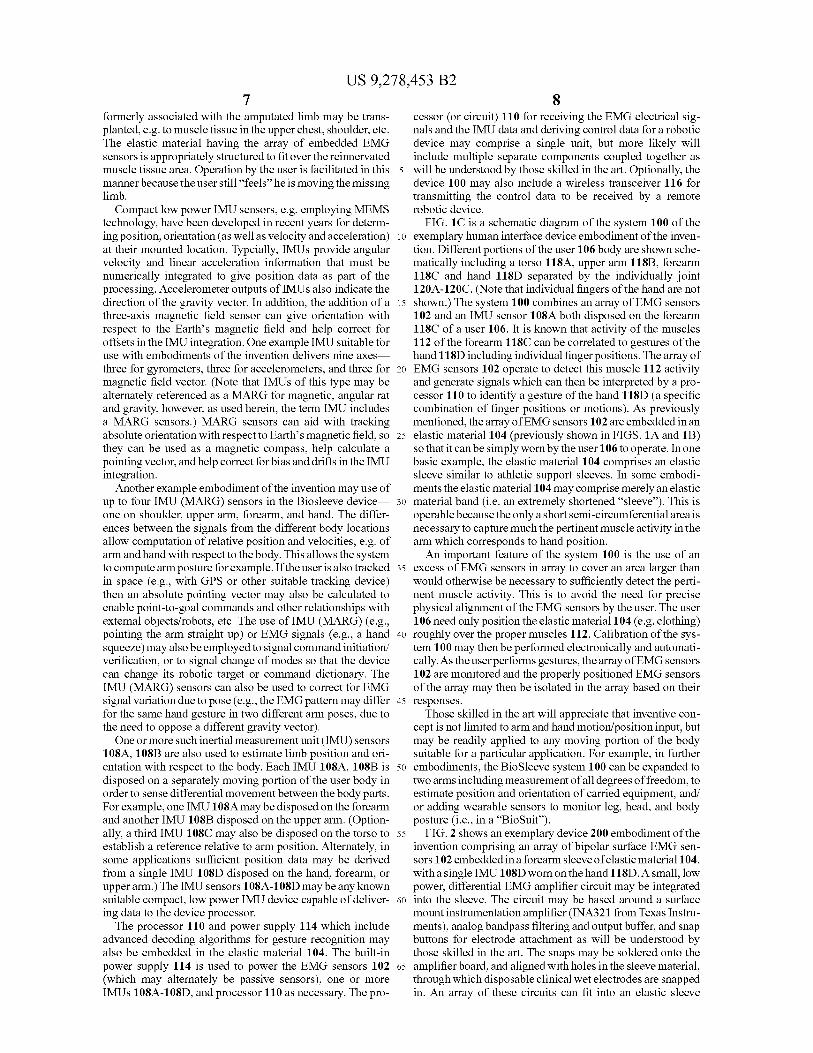
FIGS. lA and 1B show an exemplary system 100 embodi-ment of the invention and some of the related concepts. The example system 100 integrates a combination of technologies to enable detailed and accurate arm and hand tracking. An array of EMG sensors 102 are embedded into an elastic mate-rial 104 (e.g. a conventional article of clothing or even a single material sleeve worn over just a portion of the body, e.g. an arm or leg) to be unobtrusive to the user 106. The elastic material typically comprises an skin-tight material, e.g., spandex, neoprene or any other suitable material or combi-nation of material layers, capable of holding the EMG sensors 102 close enough to the users underlying muscles 112 to detect electromagnetic signals corresponding to muscle activity. The elastic material 104 fits tightly to a body portion of the user having underlying muscles such that the array of electromyography (EMG) sensors are disposed in the elastic material to be proximate to the underlying muscles of the user in order to sense activity of the underlying muscles and yield EMG electical signals therefrom. Although embodiments of the invention may be developed to operate with any body portion having relevant underlying muscles, typically the body portion may comprise the forearm. In this case, the activity of the forearm muscles can be directly correlated to hand positions and gestures.
Further embodiments of the invention may also be devel-oped to manipulate robotic limbs for amputees. The elastic material having the array of embedded EMG sensors is typi-cally structured to fit over the residual muscles on the limb. In some applications, motor nerves projecting to muscle tissue
US 9,278,453 B2 7
8 formerly associated with the amputated limb may be trans- cessor (or circuit) 110 for receiving the EMG electrical sig- planted, e.g. to muscle tissue in the upper chest, shoulder, etc. nals and the IMU data and deriving control data for a robotic The elastic material having the array of embedded EMG
device may comprise a single unit, but more likely will
sensors is appropriately structured to fit over the reinnervated
include multiple separate components coupled together as muscle tissue area. Operation by the user is facilitated in this 5 will be understood by those skilled in the art. Optionally, the manner because the user still "feels" he is moving the missing
device 100 may also include a wireless transceiver 116 for
limb. transmitting the control data to be received by a remote Compact low power IMU sensors, e.g. employing MEMS
robotic device.
technology, have been developed in recent years for determ- FIG. 1C is a schematic diagram of the system 100 of the ing position, orientation (as well as velocity and acceleration) io exemplary human interface device embodiment of the inven- at their mounted location. Typcially, IMUs provide angular tion. Different portions of the user 106 body are shown sche- velocity and linear acceleration information that must be matically including a torso 118A, upper arm 11813, forearm numerically integrated to give position data as part of the
118C and hand 118D separated by the individually joint
processing. Accelerometer outputs of IMUs also indicate the
120A-120C. (Note that individual fingers of the hand are not direction of the gravity vector. In addition, the addition of a 15 shown.) The system 100 combines an array of EMG sensors three-axis magnetic field sensor can give orientation with
102 and an IMU sensor 108A both disposed on the forearm
respect to the Earth's magnetic field and help correct for
118C of a user 106. It is known that activity of the muscles offsets in the IMU integration. One example IMU suitable for
112 of the forearm 118C can be correlated to gestures of the
use with embodiments of the invention delivers nine axes
hand 118D including individual finger positions. The array of three for gyrometers, three for accelerometers, and three for 20 EMG sensors 102 operate to detect this muscle 112 activity magnetic field vector. (Note that IMUs of this type may be and generate signals which can then be interpreted by a pro- alternately referenced as a MARL for magnetic, angular rat cessor 110 to identify a gesture of the hand 118D (a specific and gravity, however, as used herein, the term IMU includes combination of finger positions or motions). As previously a MARL sensors.) MARL sensors can aid with tracking mentioned, the array of EMG sensors 102 are embedded in an absolute orientation with respect to Earth's magnetic field, so 25 elastic material 104 (previously shown in FIGS. lA and 113) they can be used as a magnetic compass, help calculate a so that it can be simply worn by the user 106 to operate. In one pointing vector, and help correct for bias and drifts in the IMU
basic example, the elastic material 104 comprises an elastic
integration. sleeve similar to athletic support sleeves. In some embodi- Another example embodiment of the invention may use of
ments the elastic material 104 may comprise merely an elastic
up to four IMU (MARG) sensors in the Biosleeve device 30 material band (i.e. an extremely shortened "sleeve"). This is one on shoulder, upper arm, forearm, and hand. The differ- operable becausethe only a short semi-circumferential area is ences between the signals from the different body locations necessary to capture much the pertinent muscle activity in the allow computation of relative position and velocities, e.g. of
arm which corresponds to hand position.
arm and hand with respect to the body. This allows the system
An important feature of the system 100 is the use of an to compute arm posture for example. If the user is also tracked 35 excess of EMG sensors in array to cover an area larger than in space (e.g., with GPS or other suitable tracking device)
would otherwise be necessary to sufficiently detect the perti-
then an absolute pointing vector may also be calculated to nent muscle activity. This is to avoid the need for precise enable point-to-goal commands and other relationships with
physical alignment of the EMG sensors by the user. The user
external objects/robots, etc. The use of IMU (MAARG) (e.g., 106 need only position the elastic material 104 (e.g. clothing) pointing the arm straight up) or EMG signals (e.g., a hand 40 roughly over the proper muscles 112. Calibration of the sys- squeeze) may also be employed to signal command initiation/
tem 100 may then be performed electronically and automati-
verification, or to signal change of modes so that the device cally. As the userperforms gestures, the array of EMG sensors can change its robotic target or command dictionary. The
102 are monitored and the properly positioned EMG sensors
IMU (MARL) sensors can also be used to correct for EMG
of the array may then be isolated in the array based on their signal variation due to pose (e.g., the EMG pattern may differ 45 responses. for the same hand gesture in two different arm poses, due to
Those skilled in the art will appreciate that inventive con-
the need to oppose a different gravity vector). cept is not limited to arm and hand motion/position input, but One or more such inertial measurement unit (IMU) sensors may be readily applied to any moving portion of the body
108A, 108B are also used to estimate limb position and ori- suitable for a particular application. For example, in further entation with respect to the body. Each IMU 108A, 108B is 50 embodiments, the Biosleeve system 100 can be expanded to disposed on a separately moving portion of the user body in two arms including measurement of all degrees of freedom, to order to sense differential movement between the body parts. estimate position and orientation of carried equipment, and/ For example, one IMU 108A may be disposed on the forearm or adding wearable sensors to monitor leg, head, and body and another IMU 108B disposed on the upper arm. (Option- posture (i.e., in a `BioSuit"). ally, a third IMU 108C may also be disposed on the torso to 55 FIG. 2 shows an exemplary device 200 embodiment of the establish a reference relative to arm position. Alternately, in
invention comprising an array of bipolar surface EMG sen-
some applications sufficient position data may be derived
sors 102 embedded in a forearm sleeve of elastic material 104, from a single IMU 108D disposed on the hand, forearm, or with a single IMU 108D worn on the hand 118D. A small, low upper arm.) The IMU sensors 108A-108D may be any known power, differential EMG amplifier circuit may be integrated suitable compact, low power IMU device capable of deliver- 60 into the sleeve. The circuit may be based around a surface ing data to the device processor. mount instrumentation amplifier (INA321 from Texas Instru-
The processor 110 and power supply 114 which include ments), analog bandpass filtering and output buffer, and snap advanced decoding algorithms for gesture recognition may
buttons for electrode attachment as will be understood by
also be embedded in the elastic material 104. The built-in those skilled in the art. The snaps may be soldered onto the power supply 114 is used to power the EMG sensors 102 65 amplifier board, and aligned with holes in the sleeve material, (which may alternately be passive sensors), one or more through which disposable clinical wet electrodes are snapped IMUs 108A-108D, and processor 110 as necessary. The pro- in. An array of these circuits can fit into an elastic sleeve

US 9,278,453 B2 9
material for mounting on the user's forearm 118C. Using the example circuit, the EMG signals maybe amplified, bandpass filtered, and buffered, and then transmitted through a wire tether 202 to an off-board processor 110 for digitization (which may disposed remotely elsewhere on the user, e.g. in a clothing pocket or pouch) and processing to yield the con-trol data for the robotic device. A wireless transceiver 116 may be use to communicate the derived control data to the robotic device. The example circuit characteristics may include power input of 228 µW (76 µA at 3V) during opera-tion and less than 5 µA in sleep mode, gain of 100 V/V and frequency pass band of 16 to 600 Hz.
FIG. 3 shows some example raw EMG signals from an exemplary system embodiment of the invention. Embodi-ments of the invention may be implemented with either wet clinical electrodes or dry (i.e., no contact gel) electrodes in elastic skin-tight sleeves. Using the wet adhesive electrodes may make the sleeve/sensor array more difficult to mount. Dry electrodes have a potential advantage in ease of use for mounting the Biosleeve system on the user's arm, but may have lower signal to noise ratio if not in good skin contact. The sensors require constant mechanical pressure to maintain good skin contact. Accordingly, a skin-tight properly sized material garment or sleeve is important. A system with six-teen channels of bipolar sensor circuits for the in-sleeve array can be implemented. As previously discussed, embodiments of the invention can benefit from an oversized array of EMG sensors to avoid tedious sensor positioning and calibration. The array of EMG sensors need only be placed over the relevant muscle area and the EMG sensors of the array which happen to be over the proper muscles are selectively moni-tored.
Packaging the array in elastic sleeve materials proved to be the major challenge for reliability, because breaks in the array wiring from motion caused most experiments to be run with twelve or fewer working channels. One basic embodiment may use eight bipolar sensors with two wet adhesive elec-trodes per sensor. However, an improved embodiment of the invention may use commercial bipolar sensors with two silver bar electrodes per sensor.
3. Example Gesture Recognition with Biosleeve Human-Machine Interface
The signals acquired and filtered by human-interface embodiments of the invention may be sent off-board for ges-ture recognition processing. In some implementations, static gestures may be classified using the EMG signals in a Support Vector Machine (SVM) algorithm and dynamic gestures may use IMU data in a custom technique founded on a spatial pattern recognition/dynamic programming technique. Fur-ther embodiments of the invention can integrate both EMG and IMU signals for both types of gestures. After donning the device, the user can complete a quick 2-5 minute calibration exercise, which collects data in each gesture to train the classifiers.
In some embodiments, static gestures maybe implemented to enable a "virtual joystick? with five basic commands: left, right, forward, backward, and stop. These commands may be accomplished with hand position only (allowing any arm position/orientation) and thus required only EMG signals. The classification approach may be founded on multiclass SVM, which reduces the single multiclass problem into mul-tiple binary classification problems. For example, a five-class SVM may be applied to an eight-channel EMG feature vector, where a feature is defined as the standard deviation of the EMG amplitude over the last 0.5-second window. One chal-
10 lenge of using amplitude-based signals, however, is that they can vary as the battery voltage supplied to the device decreases. Compensation for this effect can be effected in software by offsetting the feature vector by the minimum
5 value of the vector. The classification algorithms and command interfaces for
use with an embodiment of the invention may also be imple-mented on an off-board computer (although this is less desir-able than implementation on-board the device as previously
10 described), which then sends the interpreted commands to the controlled robotic device, e.g. in on example, up to five LAN-droid mobile robots (iRobot Corp., USA) in real time.
FIG. 4 illustrates the labeled EMG data for the five static gestures. The separability of the gesture classes indicates the device can provide high signal quality and data that is valu-
15 able for detecting the user's finger position (i.e. hand shape). The gesture classes can then be mapped to commands sent to one or more robotic devices, so the user can direct the robotic device with these hand shapes. Classification accuracy can be consistently over 90%, with some tests indicating virtually
20 100% accuracy (over 600 consecutive time steps), although these results may be limited to a single user operating within about 30 minutes of calibration.
To classify dynamic gestures, patterns of feature vector changes over time need to be detected and extracted.
25 Dynamic programming (DP) can be used in the analysis, as it was previously successfully demonstrated for gesture recog-nition due to its ability to optimally compensate for nonlinear time fluctuations of gestures. During training and testing recognition the movements can be repeated a number of times.
30 FIGS. 5A and 5B show nine different dynamic gestures (D I to D9) which can be captured combining EMG and IMU sensor data to reflect gestures involving motion of the fingers and arm (including hand). Five significant frames are shown for each dynamic gesture (DI to D9) over a complete period,
35 or hand/arm movement return to the starting position (which may not be needed for all gestures). Typically, the array of EMG sensors provides finger position and arm rotation infor-mation and the one or more IMUs provide hand position and arm position information. In addition, the EMG array and
40 IMUs are now used to detect dynamic movements of the fingers and arm as gestures.
Although the system should be calibrated to the user for optimal results, the system will generalize well to any user because of the similarities in anatomy of the human arm and
45 muscles. EMG data analysis for detailed gestures and hand/ fingerposes may be more challenging, because the signals are stochastic and noisy, active muscles overlap for various movements (many to many mapping between muscles and fingers), and forearm movements such as twist tend to shift
50 the electrodes with the skin over the underlying muscles. However, detailed gesture sensing readily achievable employing an embodiment of the invention as will be under-stood by those skilled in the art.
Collecting simultaneous EMG data from the forearm 55 employing an embodiment of the invention with a sufficient
density of EMG sensors in the array and active channel selec-tion, one can distinguish patterns of muscle activities under-lying different hand and finger motions, including individual finger motions and twisting motions of the forearm. This
60 discrimination capability will be particularly important for correct classification between two similar hand/finger con-figurations, such as those shown in FIGS. 3A and 3B.
4. Exemplary Method of Sensing User Input 65
FIG. 6 is a flowchart of an exemplary method 600 of sensing user input. The method 600 includes an operation 602

US 9,278,453 B2 11
12
of fitting an elastic material tightly to a body portion of a user, 5. The apparatus of claim 1, wherein the body portion
the body portion having underlying muscles of the user, and
comprises a forearm of the user and the derived control data
an array of electromyography (EMG) sensors disposed in the corresponds to hand and arm gestures of the user. elastic material to be proximate to the underlying muscles of 6. The apparatus of claim 5, wherein the plurality of IMUs the user. Next in operation 604, activity of the underlying 5 comprise three IMUs, one on a forearm of the user, one on an muscles is sense with the array of EMG sensors to yield EMG upper arm of the user, and one on the torso of the user.
electrical signals therefrom. In operation 606, position and
7. The apparatus of claim 5, wherein the array of EMG
orientation at each of one or more inertial measurement units sensors provides finger position and arm rotation information
(IMUs) is determined, each disposed on the user, and corre- and the one or more IMUs provide hand position and arm sponding IMU data is yielded. In operation 608, control data io position information.
is derived for a robotic device with a processor from the EMG
8. The apparatus of claim 7, wherein the fingerposition and
electrical signals and the IMU data. In operation 610, the the arm rotation information and the hand position and the
signal processor and the one or more IMUs are powered with
arm position information correspond to static or dynamic a power supply. gestures of the user.
This method 600 may be altered consistent with the various 15 9. A method for sensing user input, comprising:
apparatus embodiments previously described. For example, fitting an elastic material tightly to a body portion of a user,
some embodiments may include the additional operation of
the body portion having underlying muscles of the user,
transmitting the control data to be received by the remote and an array of electromyography (EMG) sensors dis-
robotic device with a wireless transceiver. It is important to posed in the elastic material to be proximate to the
also note that the steps may be performed in any suitable order 20 underlying muscles of the user;
(or simultaneously) as will be appreciated by those skilled in sensing activity of the underlying muscles with the array of the art. EMG sensors to yield EMG electrical signals therefrom;
This concludes the description including the preferred
determining position and orientation of each of a plurality
embodiments of the present invention. The foregoing descrip- of inertial measurement units (IMUs) each disposed on
tion including the preferred embodiment of the invention has 25 a separately moving portion of the user in order to sense
been presented for the purposes of illustration and descrip- differential movement between body parts and yielding
tion. It is not intended to be exhaustive or to limit the invention corresponding IMU data each IMU providing nine-axis
to the precise forms disclosed. Many modifications and varia- measurements, three for gyrometers, three for acceler-
tions are possible within the scope of the foregoing teachings. ometers and three for magnetic field vector;
Additional variations of the present invention may be devised
30 deriving control data for a robotic device with a processor
without departing from the inventive concept as set forth in
from the EMG electrical signals and the IMU data; and the following claims. powering the processor and the one or more IMUs with a
power supply. What is claimed is:
10. The method of claim 9, wherein the array of EMG 1. An apparatus for sensing user input, comprising: 35 sensors is disposed to exceed an area of the body portion such
an elastic material for fitting tightly to a body portion of a that only an active subset of the EMG sensors are identified to
user, the body portion having underlying muscles of the sense the activity of the underlying muscles and yield the user;
EMG electrical signals therefrom.
an array of electromyography (EMG) sensors disposed in
11. The method of claim 9, wherein the EMG electrical the elastic material to be proximate to the underlying 40 signals and the IMU data correspond to static or dynamic
muscles of the user in order to sense activity of the gestures of the user.
underlying muscles and yield EMG electrical signals
12. The method of claim 9, further comprising transmitting therefrom; the control data to be received by the robotic device with a
• plurality of inertial measurement units (IMUs) each dis- wireless transceiver.
posed on a separately moving portion of the user for 45 13. The method of claim 9, wherein the body portion com-
determining position and orientation of each of the plu- prises a forearm of the user and the derived control data
rality of inertial measurement units (IMUs) in order to corresponds to hand and arm gestures of the user.
sense differential movement between body parts and
14. The method of claim 13, wherein the plurality of IMUs
yielding corresponding IMU data, each IMU providing comprise three IMUs, one on a forearm of the user, one on an nine-axis measurements, three for gyrometers, three for 50 upper arm of the user, and one on the torso of the user. accelerometers and three for magnetic field vector;
15. The method of claim 13, wherein the array of EMG
• processor for receiving the EMG electrical signals and
sensors provides finger position and arm rotation information
the IMU data and deriving control data for a robotic and the plurality of IMUs provide hand position and arm device; and
position information.
• power supply powering the processor and the plurality of
55 16. The method of claim 15, wherein the finger position IMUs. and the arm rotation information and the hand position and
2. The apparatus of claim 1, wherein the array of EMG
the arm position information correspond to static or dynamic
sensors is disposed to exceed an area of the body portion such
gestures of the user.
that only an active subset of the EMG sensors are identified to
17. An apparatus for sensing user input, comprising:
sense the activity of the underlying muscles and yield the 60 a plurality of muscle activity sensing means for sensing EMG electrical signals therefrom. activity of underlying muscles of a body portion of a user
3. The apparatus of claim 1, wherein the EMG electrical
and yielding electrical signals therefrom, the plurality of
signals and the IMU data correspond to static or dynamic sensor means disposed in an array; gestures of the user. a plurality of inertial sensing means for determining posi-
4. The apparatus of claim 1, further comprising a wireless 65 tion and orientation of each of the plurality of inertial
transceiver for transmitting the control data to be received by sensing means, each inertial sensing means disposed on the remote robotic device. a separately moving portion of the user, in order to sense

US 9,278,453 B2 13 14
differential movement between body parts and yielding corresponding inertial data, each inertial sensing means providing nine-axis measurements, three for gyrom-eters, three for accelerometers and three for magnetic field vector; s
• processing means for deriving control data for a robotic device from the electrical signals and the inertial data; and
• supply means for powering the processing means and the plurality of inertial sensing means. io
18. The apparatus of claim 17, wherein the array of muscle activity sensing means is disposed to exceed an area of the body portion such that only an active subset of the muscle activity sensing means are identified to sense the activity of the underlying muscles and yield the electrical signals there- is from.