U.S. Pat.No. 6,571,625 for Steam Boilers Series PS-852 for ...
12
Series PS-802 for Steam Boilers Series PS-852 for Hot Water Boilers Probe Type Low Water Cut-Offs Applications: – For residential and commercial applications – For applications that require ANSI Z21.13a conformance PS-852 models can be used as secondary low water cut-offs on steam boilers with pressures up to 15 psi ® • Before using this product read and understand instructions. • Save these instructions for future reference. • All work must be performed by qualified personnel trained in the proper application, installation, and maintenance of plumbing, steam, and electrical equipment and/or systems in accordance with all applicable codes and ordinances. • To prevent flooding, do not use manual reset models with electric automatic water feeders. • To prevent electrical shock, turn off the electrical power before making electrical connections. • This low water cut-off must be installed in series with all other limit and operating controls installed on the boiler. After installation, check for proper operation of all of the limit and operating controls, before leaving the site. • We recommend that secondary (redundant) Low Water Cut-Off controls be installed on all steam boilers with heat input greater than 400,000 BTU/hour or operating above 15 psi of steam pressure. At least two controls should be connected in series with the burner control circuit to provide safety redundancy protection should the boiler experience a low water condition. Moreover, at each annual outage, the low water cut-offs should be dismantled, inspected, cleaned, and checked for proper calibration and performance. • When installing jumper wire make sure you are not introducing a second voltage source into the burner circuit and thereby bypassing other safety, limit, and operating controls. Failure to follow this warning could cause property damage, personal injury or death. WARNING CAUTION ! WARNING U.S. Pat. No. 6,571,625 McDonnell & Miller Installation & Maintenance Instructions MM-216(J)
Transcript of U.S. Pat.No. 6,571,625 for Steam Boilers Series PS-852 for ...

Series PS-802for Steam BoilersSeries PS-852for Hot Water Boilers
Probe Type Low Water Cut-Offs
Applications:– For residential and commercial applications– For applications that require ANSI Z21.13a conformance
PS-852 models can be used as secondary low water cut-offson steam boilers with pressures up to 15 psi
®
• Before using this product read and understand instructions.
• Save these instructions for future reference.
• All work must be performed by qualified personnel trained in the proper application,installation, and maintenance of plumbing, steam, and electrical equipment and/or systems in accordance with all applicable codes and ordinances.
• To prevent flooding, do not use manual reset models with electric automatic water feeders.
• To prevent electrical shock, turn off the electrical power before making electrical connections.
• This low water cut-off must be installed in series with all other limit and operating controls installed on the boiler. After installation, check for proper operation of all of the limit and operating controls, before leaving the site.
• We recommend that secondary (redundant) Low Water Cut-Off controls be installed on all steam boilers with heat input greater than 400,000 BTU/hour or operating above 15 psi of steam pressure. At least two controls should be connected in series with the burner control circuit to provide safety redundancy protection should the boiler experience a low water condition. Moreover, at each annual outage, the low water cut-offs should be dismantled,inspected, cleaned, and checked for proper calibration and performance.
• When installing jumper wire make sure you are not introducing a second voltage source into the burner circuit and thereby bypassing other safety, limit, and operating controls.
Failure to follow this warning could cause property damage, personal injury or death.
WARNINGCAUTION
! WARNING
U.S. Pat. No. 6,571,625
McDonnell & MillerInstallation & Maintenance
Instructions MM-216(J)
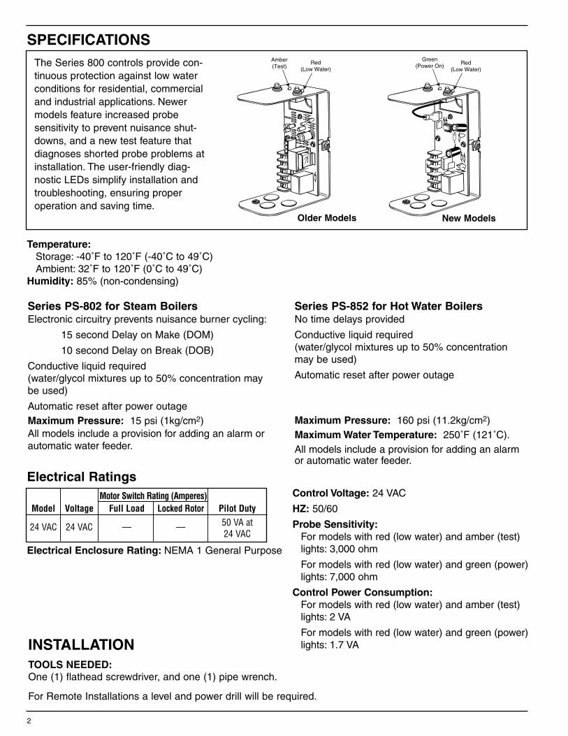
Green(Power On) Red
(Low Water)
2
SPECIFICATIONS
INSTALLATIONTOOLS NEEDED:One (1) flathead screwdriver, and one (1) pipe wrench.
For Remote Installations a level and power drill will be required.
Electrical Ratings
Series PS-802 for Steam BoilersElectronic circuitry prevents nuisance burner cycling:
15 second Delay on Make (DOM)
10 second Delay on Break (DOB)
Conductive liquid required(water/glycol mixtures up to 50% concentration maybe used)
Automatic reset after power outageMaximum Pressure: 15 psi (1kg/cm2)All models include a provision for adding an alarm orautomatic water feeder.
Series PS-852 for Hot Water BoilersNo time delays provided
Conductive liquid required(water/glycol mixtures up to 50% concentrationmay be used)
Automatic reset after power outage
Maximum Pressure: 160 psi (11.2kg/cm2)Maximum Water Temperature: 250˚F (121˚C).All models include a provision for adding an alarmor automatic water feeder.
Control Voltage: 24 VAC
HZ: 50/60
Probe Sensitivity:For models with red (low water) and amber (test) lights: 3,000 ohm
For models with red (low water) and green (power) lights: 7,000 ohm
Control Power Consumption:For models with red (low water) and amber (test) lights: 2 VA
For models with red (low water) and green (power) lights: 1.7 VA
Motor Switch Rating (Amperes)Model Voltage Full Load Locked Rotor Pilot Duty
24 VAC 24 VAC — — 50 VA at24 VAC
The Series 800 controls provide con-tinuous protection against low waterconditions for residential, commercialand industrial applications. Newermodels feature increased probe sensitivity to prevent nuisance shut-downs, and a new test feature thatdiagnoses shorted probe problems atinstallation. The user-friendly diag-nostic LEDs simplify installation andtroubleshooting, ensuring properoperation and saving time.
Amber(Test)
Red(Low Water)
Older Models New Models
Temperature:Storage: -40˚F to 120˚F (-40˚C to 49˚C)Ambient: 32˚F to 120˚F (0˚C to 49˚C)
Humidity: 85% (non-condensing)
Electrical Enclosure Rating: NEMA 1 General Purpose

3
AD
a. Based on the following criteria locate a suitable position for the probe (A):
b. Sparingly, apply pipe sealant to the externalthreads (D) of the probe (A).
For all Applications:1. Make sure probe is installed above minimum
safe water line as determined by the boiler manufacturer.
2. Make sure that ends and sides of the probe are at least 1/4" (6.4mm) from all internal metal surfaces.
3. Make sure the probe is positioned to shut off the boiler before the water level falls below the lowest visible part of the gauge glass.
For Steam Boilers:1. Refer to boiler manufacturers instructions to
determine suitable tapping for the probe.
For Hot Water Boilers:1. Refer to boiler manufacturers instructions to
determine suitable tapping for the probe.
2. Locate probe in supply piping using a tee fitting.
STEP 1 - Locating and Installing the Probe
1/4"(6mm)
1/4" (6mm)
A
E
A
Fc. Using a wrench, tighten the probe (A) intothe tapped connection (E) that was deter-mined in Step 1 of these instructions.Tighten to 47 ft•lb (64 N•m).NOTE: Be sure to align the probe so thatthe mounting screws (F) are in a horizontalposition.
IMPORTANT: Do not use Teflon® tape. Only usepipe sealant.
ProbeControl
RiserPipe
Hot WaterBoiler
Tee Fitting
ProbeControl
Minimum SafeWater Level(May vary by boiler
manufacturer)
Steam orHot Water
Boiler

4
G
F
F
b. Using a flathead screwdriver, loosen theprobe mounting screws (F) 1/8" (3mm) about1-1/2 turns and slip the control housing (G)over these two screws at a 20˚ angle.
G
c. Rotate the control housing (G) 20˚ counter-clockwise so that the slots in the control baseare firmly under the screw heads. Tighten themounting screws (F) to approximately 2 ft•lb(2.6 N•m).
d. Identify a desirable location to mount the control assembly (G) and comply with the following steps:
1. Using a level, draw a horizontal line at thelocation and mark two positions 1-1/4"(31.75 mm) apart on the horizontal line.
2. Drill a 0.113 dia. hole 1/2" (13 mm) deepin each position on the horizontal line.
3. Insert the two (2) sheet metal screws (pro-vided) into the two holes. Using a flatheadscrewdriver, tighten the screws so that thebase of the screw head is 1/8" from themounting surface.* Repeat Steps 2b. and 2c. above.
1 1/4"(31.75mm)
Remote Mounting
Direct Mounting
STEP 2 - Installing Control Box
G
a. Using a flathead screwdriver, loosen the two (2)screws that secure the cover (G) to the controlabout 1-1/2 turns and remove cover.
5
LK
J
Aa. Slip the ring terminal lead (J) followed by the
lockwasher (K) over the threaded end of theprobe (A). Tighten the wing nut (L) onto theprobe to approximately 1/2 ft•lb (.65 N•m).
J3
QA
b. Connect the probe (A) to the wiring circuit by slidingthe female quick-connect terminal of the probe wireonto the male spade terminal J3 probe (terminal maybe marked J7 on older units).
Remote Mounted Probe
Direct Mounted Probe
1. Connecting a suitable 16 AWG wire (not provided) to the threaded end (V) of the probe (A).
2. Place the lockwasher (K) and wing nut (L) (provided) over the threaded end of the probe and tighten the wing nut to 1/2 ft•lb (.65 N•m).
3. Using a flathead screwdriver, attach a suitable green 16 AWG wire (not provided) to the green ground screw (X) (provided) at the base of the probe.
4. Route the two wires through a protected wire way to the control unit (G) through the conduit knock-outs in the base of the control.
5. Using the female quick-connect terminal (QQ) provided, connect the wire, from step 1, to the male spade terminal marked “PROBE” (J3). On older units, use the “P” terminal block or (J7) terminal spade connection.
6. Using a flathead screwdriver, connect the green wire, from Step 3, to the green ground screw (W) on the housing of the control.
c. Connect the probe (A) to the wiring circuit by:
L
AK
X
V
QQJ
W
GG R
GR
EE
N
J3
S
ONCIRCUITBOARD
STEP 3 - Probe Wiring

6
STEP 4 - Control Wiring
• To prevent electrical shock, turn off the electrical power before making electrical connections.
• This low water cut-off must be installed in series with all other limit and operating controls installed on the boiler. After installation, check for proper operation of all of the limit and operating controls, before leaving the site.
• All work must be performed by qualified personnel trained in the proper application, installation, and maintenance of plumbing, steam, and electrical equipment and/or systems in accordance with all applicable codes and ordinances.
Failure to follow this warning could cause electrical shock, an explosion and/or fire, which could result in property damage, personal injury or death.
! WARNING
OFF
ONa. Turn off all power to boiler and boiler controls.
b. Electrical Conduit Connection• Connect electric conduit using knockouts provided.• Follow accepted electrical practices when installing fittings and making connections.• Refer to and follow local codes and standards when selecting the types of electrical fittings and conduit.
c. Based on the Boiler’s Control Circuit voltage and the required input voltage of the LWCO, select properwiring diagram and proceed to that page.
Boiler manufacturer schematics should always befollowed. In the event that the boiler manufacturer’sschematic does not exist, or is not available fromthe boiler manufacturer, refer to the schematicsprovided in this document.
! IMPORTANTTo prevent an electrical fire or equipment damage,electrical wiring must have a rating of 167˚F (75˚C) if the liquid's temperature exceeds 180˚F (82˚C).Failure to follow this warning could cause property damage, personal injury or death.
! WARNING
Models with Red (low water) and Amber Lights (test) Models with Red (low water) and Green (power) Lights
LWCO Model Boiler Circuit Voltage Page LWCO Model Boiler Circuit Voltage Page
PS-802-24 24V using Harness 7 PS-802-24 24V using Harness 7
PS-802-24 24V using Terminals 7 PS-802-24 24V using Terminals 7
PS-852-24 24V using Harness 7 PS-852-24 24V using Harness 7
PS-852-24 24V using Terminals 7 PS-852-24 24V using Terminals 7
Do not use "manual reset" models with electric automatic water feeders.
Failure to follow this caution can cause flooding and property damage.
! CAUTION

A
B
7
Wiring harness is provided by boiler manufacturer.
NOTE
Do not use force to insert plug. This may damagereceptacle solder connections.
! CAUTION
N
P
M
d. For all wire connections to the terminal block (M).
1. Strip about 1/3" (8.5 mm) of insulation fromthe wire.
2. Loosen the terminal screw (N) but DO NOT REMOVE. Move the wire clamping plate (P) back until the plate touches the back sideof the screw head.
3. Insert the stripped end of the wire under the wire clamping plate (P) and securely tighten the terminal screw (N).
Wiring Diagram Legends1. Bold lines indicate action to be taken in Step shown.
2. Dotted black lines indicate internal wiring.
Connect plug (A) of wiring harness to receptacle (B).
Check to make sure factory supplied jumper isinstalled between terminals (H) and (C).
PS-802/852 using Harness Connection
PS-802/852 using Terminal Connections
D
N H C W B
BURNERCIRCUIT
C
B
A
24 VOLTPOWERCIRCUIT
JUMPERBAR
N HB• Connect neutral wire (A) of 24 volt circuit to terminal (N).• Connect hot wire (B) of 24 volt circuit to terminal (H).• Connect wire (C) from beginning of Burner circuit
(thermostat, gas valve, limits, etc.) to terminal (B).• Connect wire (D) from end of Burner circuit to terminal (N).• Make sure factory provided jumper bar is connected to
terminal (H) and (C).
G
e. Place the cover on the control housing, and, using a flathead screwdriver, tighten the two (2) screws into the control housing and cover (G) to approximately 2 ft•lb (2.6 N•m).
INSTALLATION COMPLETE

8
STEP 5 - Testing
All Models with Red (Low Water) and Amber (Test) Lights
OFF
ON
a. Before filling the system, turn on the electric power to the boiler. Set the room thermostat to "heat".
For Series PS-802 the burner will come on briefly (10 seconds or less) and then shut off which verifies proper operation. The burner will not operate without water in the system. The low water cut-off's red LED should be illuminated.
For Series PS-852 the burner will come on briefly and then shut off, verifying proper operation. The burner will not operate without water in the system.The low water cut-off's red LED should be illuminated.
b. Fill the system with water.
For Series PS-802 the low water cut-off's red LED should shutoff in about 15 seconds, after the water contacts the probe.
For Series PS-852 the low water cut-off's red LED should shutoff after the water contacts the probe.
AA BB
G
c. Hold the test switch (AA) down while noting the amber LED (BB) on top of the control housing (G).1. If the amber LED (BB) glows dimly, the water
level is above the probe.
2. If the amber LED (BB) is off, the water level may be below the probe or the water is too pure and may require the addition of boiler water treatment.
3. If the amber LED (BB) glows brightly, it could indi-cate a grounded (non-operable) probe. If this is the case, proceed to "Troubleshooting".
AA
d. Test for correct burner circuit wiring.1. Hold down the test switch (AA) while the burner
is running for more than:
• 12 seconds for PS-802
• 2 seconds for PS-852
2. If the burner shuts off while the test switch is depressed, the burner circuit is wired correctly.
AA CC
e. For the automatic reset models - Release thetest switch (AA) and the burner should resumefiring provided that the boiler water is in contactwith the probe.For the manual reset models - The burner willnot return to normal operation until the resetswitch (CC) is set.
f. Check for proper operation of all of the limit and operat-ing controls, before leaving the site.
PageAll Models with Red (Low Water) and Amber (Test) Lights 8Series PS-802 and PS-802-M with Red (Low Water) and Green (Power) Lights 9Series PS-852 and PS-852-M with Red (Low Water) and Green (Power) Lights 10
9
b. Now fill the boiler with water.For Series PS-802 (auto reset units only)1. When water touches the probe, the Red light will start flashing for 15-seconds Delay on Make (DOM)
and then turn "OFF".2. The burner will turn "ON" as long as there is water on the probe.3. If a water feeder has been installed it will turn "OFF".
For Series PS-802-M (manual reset units only)(When water returns to the probe, nothing will happen until the manual reset button is depressed.)1. After depressing manual reset button, the Green and Red lights will flash simultaneously 4 times.2. Then the Green light will turn "ON".3. The Red light will continue to flash for 15-seconds (DOM) and then turn "OFF".4. The burner should turn "ON" as long as there is water on the probe.(Warning: To prevent flooding, never use an electric automatic water feeder with a manual reset low watercut-off.)
c. Slowly drain the boiler of water.For all Series PS-802 (both auto and manual reset units)1. When water drops off the probe, the Red light will start flashing for 10-seconds (DOB) and then turn "ON".2. The burner will turn "OFF".3. If a water feeder has been installed and does not have a time delay, it should turn "ON".(Warning: To prevent flooding, never use an electric automatic water feeder with a manual reset low watercut-off.)
Manually Testing Control
For Series PS-802 & PS-802-M with Red (Low Water) andGreen (Power) Lights
a. Before filling the system, turn on the electric power to the boiler. Set the thermostat to "heat".
For all Series PS-8021. Upon initial power up, the Green and Red lights will flash simultaneously 4 times.2. The Green light will turn "ON".3. The Red light will continue to flash for 10-seconds Delay on Break (DOB) and then turn "ON".4. If a water feeder has been installed and does not have a time delay, it will turn "ON".5. The burner will never turn "ON" during power up, if water is off the probe.
Start-Up
d. Depressing test button with "water on probe" for Series PS-802 (auto reset units only):(Must depress and hold the test button for more than 2 seconds to activate test cycle.)1. When test cycle is activated the Green and Red lights will flash.2. After 10 seconds (DOB) the Red light will turn "ON".3. Burner will turn "OFF".4. The Green light will continue flashing as long as test button is depressed.5. If a water feeder has been installed and does not have a time delay, it will turn "ON".
(Release test button, if water is still on probe)
6. The Green light will stop flashing and turn "ON".7. The Red light will start flashing for 15 seconds (DOM) and then turn "OFF".8. Burner will turn "ON" as long as there is water on the probe.9. If a water feeder has been installed it will turn "OFF".
Testing Control Using "Test Button"

10
e. Depressing test button with "water on probe" for Series PS-802-M (manual reset units only):(Must depress and hold the test button for more than 2 seconds to activate test cycle.)1. When test cycle is activated the Green and Red lights will flash.2. After 10 seconds (DOB) the Red light will turn "ON".3. Burner will turn "OFF".4. The Green light will continue flashing as long as test button is depressed.
(Release test button.You must depress the manual reset button to unlock low water cut-off.)
5. After depressing manual reset button, the Green and Red lights will flash simultaneously 4 times.6. Then the Green light will turn "ON" and the Red light will flash for 15 seconds (DOM) and then
turn "OFF".7. The burner will turn "ON" as long as there is water on the probe.(Warning:To prevent flooding, never use an electric automatic water feeder with a manual reset low watercut-off.)
f. Depressing test button with "water off probe" (both auto and manual reset units):
Since control is in "low water" the Green light will flash and the Red light will remain “ON”. The burner willremain “OFF”.
Testing Control Using "Test Button" (continued)
b. Now fill the boiler with water.For Series PS-852 (auto reset units only)1. When water touches the probe, the Green light will remain "ON".2. The Red light will turn "OFF" and the burner will turn “ON” as long as there is water on the probe.
For Series PS-852-M (manual reset units only)(When water returns to the probe, nothing will happen until the manual reset button is depressed.)1. After depressing manual reset button, the Green and Red lights will flash simultaneously 4 times.2. Then the Green light will turn "ON" and the Red light will turn “OFF”.4. The burner will turn "ON" as long as there is water on the probe.(Warning: To prevent flooding, never use an electric automatic water feeder with a manual reset low watercut-off.)
For Series PS-852 & PS-852-M with Red (Low Water) andGreen (Power) Lights
a. Before filling the system, turn on the electric power to the boiler. Set the thermostat to "heat".
For all Series PS-8521. Upon initial power up, the Green and Red lights will flash simultaneously 4 times.2. The Green and Red lights will turn "ON".3. The burner will never turn "ON" during power up, if water is off the probe.
Start-Up

11
c. Slowly drain the boiler of water.For all Series PS-852 (both auto and manual reset units)1. When water drops off the probe, the Green light will remain "ON".2. The Red light will turn “ON” and the burner will turn “OFF”, if water is off the probe.
Manually Testing Control
d. Depressing test button with "water on probe" (auto reset units only):(Must depress and hold the test button for more than 2 seconds to activate test cycle.)1. When test cycle is activated the Green light will flash.2. The Red light will turn “ON”.3. Burner will turn "OFF".4. The Green light will continue flashing as long as test button is depressed.
(Release test button, if water is still on probe)
5. The Green light will stop flashing and turn "ON".6. The Red light will turn "OFF".7. Burner will turn "ON" as long as there is water on the probe.
Testing Control Using "Test Button"
e. Depressing test button with "water on probe" (manual reset units only):(Must depress and hold test button for more than 2 seconds to activate test cycle.)1. When test cycle is activated the Green light will flash.2. The Red light will turn "ON".3. Burner will turn "OFF".4. The Green light will continue flashing as long as test button is depressed.
(Release test button.You must depress the manual reset button to unlock low water cut-off.)
5. After depressing manual reset button, the Green and Red lights will flash simultaneously 4 times.6. Then the Green light will turn "ON" and the Red light will turn "OFF".7. The burner will turn "ON" as long as there is water on the probe.(Warning:To prevent flooding, never use an electric automatic water feeder with a manual reset low watercut-off.)
f. Depressing test button with "water off probe" (both auto and manual reset units):Since control is in "low water" the Green light will flash and the Red light will remain “ON”. The burner willremain “ OFF”.
If control fails to operate as required, perform the following diagnostic checks:
1. Check to be sure that the water level in the boiler is at or above the level of the probe.
2. Re-check all wiring to ensure proper connections as specified in boiler manufacturer’s wiring diagrams or these instructions.
3. Check to ensure that Teflon® tape has not been used on the threaded connection of the electrode to the boiler.
4. Re-check the electrical ground connection for the remote sensor and control unit.
5. Check the quality of the boiler water to ensure adequate conductance.
Troubleshooting
Replace Probe if:• Teflon® insulator is cracked or worn.• Probe is loose.Failure to follow this caution could cause property damage, personal injury or death.
CAUTION!
Clean probe by wiping with non-abrasive cloth and rinsing with clean water. DO NOTuse sharp instruments to remove any accumulations of rust or scale.
NOTE
MAINTENANCESCHEDULE:
• Test the low water cut-off annually or more frequently.• Remove and inspect the self-cleaning probe every 5 years.• Replace probe every 10 years.• Replace the low water cut-off every 15 years.
ITT8200 N. Austin Ave.Morton Grove, IL 60053tel: 847-966-3700fax: 847-966-9052www.mcdonnellmiller.com
McDonnell & Miller
©2007 ITT Corporation Printed in U.S.A. 11-07 246808