US EVA 12 (CHARLIE) 1 EVA/10A STG/FIN - NASA 16 10A Stage - US EVA 12 (Charlie) TIME (HR : MIN) IV...
51
Increment 16 10A Stage - US EVA 12 (Charlie) TIME (HR : MIN) IV EV1 EV2 US EVA 12 (CHARLIE) 1 EVA/10A STG/FIN 00:00 --- POST DEPRESS (00:05) POST DEPRESS (00:05) EGRESS/SETUP (00:10) EGRESS/SETUP (00:10) - REMOVE PORT SHUNT JUMPER (00:30) CONFIGURE VENT TOOLS (00:40) -- - VENT AND STOW PORT SHUNT JUMPER (00:50) REMOVE NODE 2 FLUID QD CAPS (00:25) 01:00 --- - RELOCATE APFR (00:15) -- RELEASE LOOP B FLUID TRAY (00:50) RELEASE LOOP B FLUID TRAY (00:50) - 02:00 --- - RELOCATE LOOP B FLUID TRAY (00:30) RELOCATE LOOP B FLUID TRAY (00:30) -- - SECURE LOOP B FLUID TRAY (00:20) SECURE LOOP B FLUID TRAY (00:20) 03:00 --- DEPLOY NODE 2 LOOP B FLUID TRAY (00:20) DEPLOY NODE 2 LOOP B FLUID TRAY (00:20) - -- VENT NODE 2 LOOP B FLUID TRAY (00:40) MATE/OPEN TRAY HINGE QDS (00:30) - 04:00 --- MATE/OPEN NODE 2 QDS (00:55) - MATE/OPEN S0 QDS (00:45) -- - 05:00 --- CONFIGURE LOOP B TRAY HEATER CABLE (00:15) MATE NODE 2 STBD AVIONICS CABLES (00:30) - NODE 2 STBD CBCS COVER & CBM PETALS (00:10) MATE PMA2-NODE 2 REDUNDANT UMBILICALS (00:35) -- LAB-NODE 2 GAP SPANNER (00:25) - 06:00 --- CLEANUP/INGRESS (00:20) CLEANUP/INGRESS (00:20) - EVA = 6:25 PRE REPRESS (00:05) PRE REPRESS (00:05)
Transcript of US EVA 12 (CHARLIE) 1 EVA/10A STG/FIN - NASA 16 10A Stage - US EVA 12 (Charlie) TIME (HR : MIN) IV...

Increment 16 10A Stage - US EVA 12 (Charlie)
TIME (HR : MIN)
IV EV1 EV2
US EVA 12 (CHARLIE) 1 EVA/10A STG/FIN
00:00 --- POST DEPRESS (00:05) POST DEPRESS (00:05) EGRESS/SETUP (00:10) EGRESS/SETUP (00:10)
- REMOVE PORT SHUNT JUMPER (00:30) CONFIGURE VENT TOOLS (00:40)
--
- VENT AND STOW PORT SHUNT JUMPER (00:50) REMOVE NODE 2 FLUID QD CAPS (00:25)
01:00 ---
- RELOCATE APFR (00:15)
-- RELEASE LOOP B FLUID TRAY (00:50) RELEASE LOOP B FLUID TRAY (00:50)
-
02:00 ---
- RELOCATE LOOP B FLUID TRAY (00:30) RELOCATE LOOP B FLUID TRAY (00:30)
--
- SECURE LOOP B FLUID TRAY (00:20) SECURE LOOP B FLUID TRAY (00:20)
03:00 --- DEPLOY NODE 2 LOOP B FLUID TRAY (00:20) DEPLOY NODE 2 LOOP B FLUID TRAY (00:20)
-
-- VENT NODE 2 LOOP B FLUID TRAY (00:40) MATE/OPEN TRAY HINGE QDS (00:30)
-
04:00 --- MATE/OPEN NODE 2 QDS (00:55)
- MATE/OPEN S0 QDS (00:45)
--
-
05:00 --- CONFIGURE LOOP B TRAY HEATER CABLE (00:15) MATE NODE 2 STBD AVIONICS CABLES (00:30)
- NODE 2 STBD CBCS COVER & CBM PETALS (00:10) MATE PMA2-NODE 2 REDUNDANT UMBILICALS (00:35)
-- LAB-NODE 2 GAP SPANNER (00:25)
-
06:00 --- CLEANUP/INGRESS (00:20) CLEANUP/INGRESS (00:20)
- EVA = 6:25 PRE REPRESS (00:05) PRE REPRESS (00:05)

PRE US EVA 12 (CHARLIE) TOOL CONFIG
US EVA 12 (CHARLIE) 2 EVA/10A STG/REV A
EV1 EV2 Prior to EVA, inspect: � MWS � MWS � RET cord for damage � BRT (L) � BRT (L) � BRT for loose fittings/screws � RET (eq-eq) � RET (eq-eq) � MWS for loose screws � Wire Ties � Wire Tie � Safety/waist tether load alleviating straps: no red � Short (3 - for PMA routing) � Short (3) � Small trash bag bristles for damage/deformation � Long (2) � Long (2) (fairleads) Note: Use Blue S/N Tethers � T-Bar � T-Bar � RET (eq-eq) (2) � RET (eq-eq) w/ PIP pin (2) � Staging Bag � RET (eq-eq) w/ PIP pin (1) � Wire Ties (2) � Fuse Tether (1) � Wire Ties (2) � Small Trash Bag � Connector Cleaner Tool Kit � Small Trash Bag � Socket Caddy � Connector Pin Straightener � Socket Caddy � 7/16 Socket - 9 ext (w/ decoration) � Probe � 7/16 Socket - 9 ext (w/ decoration) � RET (eq-eq) (2) � Velcro/Tape Caddy � RET (eq-eq) (2) � Over-gloves (2) � Pry Bar � Over-gloves (2) � Swing Arm (R) � Fuse Tether (1) � Swing Arm (R) � PGT [MTL 30.5] S/N _______ � PGT (spare) S/N _________ � PGT [MTL 30.5] S/N _______ � PGT Battery S/N _______ � PGT Battery S/N _________ � PGT Battery S/N _______ � RET (eq-eq) � Wire Tie Caddy (w/ 9 wire ties) � RET (eq-eq) � Waist Tether (R & L) � Vise Grips � Waist Tether (R & L) � D-ring Extender (R & L) � EVA Ratchet � D-ring Extender (R & L) � SAFER � Cheater Bar � SAFER � WVS � WVS � Safety Tether, 85’ � Safety Tether, 85’ � IV Bag � Crewlock Bag #4 (QD Tools) � Crewlock Bag #1 � Contamination Detection Kit � w/ RET (Lg-sm) � RET (Lg-sm) (on bag exterior) � Gold Salt Coupon (6) � Adj Equip Tether (bag exterior) � Adj Equip Tether (bag exterior to secure bag at worksite) � Color Chart (2) � Wire-ties, Long (2 - shunt jumper) (on internal RET) � Adj Equip Tether (on internal RET) � ISS Contamination Sampler (2) � 1” QD Release Tool (on internal RET) � SPD, 1” (2) � Shuttle Contamination Sampler (2) � 1” QD Bail Drive Lever (on internal RET) � Adj Equip Tether (on internal RET) � Nitrogen Dioxide Draeger Tube (6) � RET (1 to internal tether point) � SPD, 1” (2) � Ammonia Draeger Tube (6) � N2 Vent Tool � Digital camera � DCM Plug (2) - SAFER Hard Mount � RET (2 for SPDs - to internal tether points) � RET (tether camera in bag) � GP Caddy (2) � RET (1 for vent tool - to ext bag handle) � RET � Thermal Mittens (2 pr) � RET (1 to internal tether point) � to Adj Equip Tether (caps) - ext bag handle � EVA Ratchet � Button depress tool (1-in) � Wire-tie Caddy (2 - internal RETs) � Socket Caddy � RET (1 to internal tether point) � Jettison Stowage Bag � 1/2 x 8-in socket (IV Hatch) � AKT (1-in) � RET (on drawstring, bundled in bag) � 7/16 x 6-in socket (backup) � Adj Equip Tether - for handling (to RET, bundled in bag) � Total RETs sm-sm used – 16 � Adj Equip Tether (for handling) (to adj, around bundle) � D-ring extender on EVA hatch D-ring � Total RETs with PIP pin – 5 � Gap Spanner (-305 for Lab/Node2) � Total RETs Lg-sm – 2 � Long duration tie-down tethers (4) � Total Adj tethers – 7

EVA BRIEFING CARD
US EVA 12 (CHARLIE) 3 EVA/10A STG/REV A
EV 1/3______ EV 2/4______ IV 1______ IV 2______ Exercise Campout Wake-up (GMT) ____ ____ : ____ ____ Wake-up (GMT) EVA Prep start ____ ____ : ____ ____ Repress for hygiene Depress to 10.2 ____ ____ : ____ ____ Depress to 10.2 Start purge ____ ____ : ____ ____ Start purge PET 00:00 ____ ____ : ____ ____ PET 00:00 EVA Prep
Get-up plan – clothing and EMU equip bag, Hygiene break Exercise protocol review, if required Equipment lock activities – IV responsibilities Suit donning plan – special requests SAFER, MWS, tools, CL positions and bag stowage Airlock depress review EV/IV comm protocol SRMS/SSRMS initial position
EV Crew Procedure Review
Egress Plan Translations – tether swaps Order of tasks Glove inspections
Ingress Plan General Procedure Review Get ahead tasks Constraints – ground and flight
Cautions and warnings review RMS operations – comm protocol/clearances Contingency procedures – crib sheet Emergencies review
Lost comm EMU malfunctions Lost tools Lost crewmember DCS
Contamination Post EVA
Suit doffing responsibilities Post EVA plan
Lessons learned from previous EVAs

US EVA 12 (CHARLIE) INHIBIT PAD
US EVA 12 (CHARLIE) 4 EVA/10A STG/FIN
Lab Window IV 1. Close window shutter if EV crew less than 10 ft/3.5m
from window
USOS
PCU NOTE
PCUs may require up to 1 hr warm-up period before they are operational
MCC-H 1. √PCUs (two) operational in discharge mode and one of the following: A. CCS PCU EVA Hazard Control enabled B. No more than two arrays unshunted C. No more than two arrays pointed < 105 deg from velocity vector OR
2. One or no PCUs operational in discharge mode and one of the following:
A. No more than two arrays unshunted B. No more than two arrays pointed < 105 deg from velocity vector
Ground Radar MCC-H 1. √TOPO and FDO consoles, ground radar restrictions in place for EVA
Cont on next page
USOS
Lab Loop B Fluid Tray Heater Umbilical Mates MCC-H 1. RPCM S01A_D RPC 2 – Open, Close Cmd Inhibit
Lab/Node 2 Loop B/Stbd Avionics Umbilical Mates MCC-H 1. MBSU 2 RBI 3 & 10 – Open, Close Cmd Inhibit 2. MBSU 3 RBI 2 & 3 – Open, Close Cmd Inhibit 3. RPCM S01A_D RPC 2 – Open, Close Cmd Inhibit 4. RPCM S02B_D RPC 4 & 5 – Open, Close Cmd Inhibit
Get Ahead: SSPTS Umbilical Mates MCC-H 1. DDCU LA1A or DDCU LA4A Converter – OFF 2. DDCU LA2A or DDCU LA3B Converter – OFF 3. RPCM LA1A4A_D RPC 3 – Open, Close Cmd Inhibit 4. RPCM LA2A3B_D RPC 1 – Open, Close Cmd Inhibit 5. RPCM Z13B_A RPC 2 – Open, Close Cmd Inhibit 6. RPCM Z14B_A RPC 2 – Open, Close Cmd Inhibit

US EVA 12 (CHARLIE) INHIBIT PAD
US EVA 12 (CHARLIE) 5 EVA/10A STG/FIN
RSOS
SM Antennas MCC-M 1. Global Timing Sys 1(400.1 MHz) [GTS] – Deactivate 2. ARISS (HAM Radio) – Deactivate or VHF
(144-146 MHz) TX only
FGB Antennas MCC-M 1. ARISS – Deactivate
FGB Thrusters MCC-M 1. √FGB MCS unpowered 2. √All FGB Attitude Control Thruster Valves (eighty) – closed 3. √FGB Attitude Control Manifold Valves – closed КШК1, КШК2, КШК4, КШК5, КШК9, ОКО3, ОКГ3, ОКО6, ОКГ6, ОКО7, ОКГ 7, ОКО8, ОКГ8
Soyuz Antennas MCC-M 1. √Soyuz KURS A [КУРС A] – Deactivated
Soyuz Thrusters MCC-M 1. √Soyuz manifolds (four) – closed ЭКО1, ЭКО2, ЭКГ1, ЭКГ2 2. √Soyuz MCS unpowered 3. √Soyuz Attitude Control Thruster Valves (fifty-two) – closed 4. √Soyuz Main Engine Valves (K1,K2,K3,K4,K5,K6) – closed

EVA NOTES, CAUTIONS, AND WARNINGS
US EVA 12 (CHARLIE) 6 EVA/10A STG
NOTES 1. For bolt install: report good/nominal torque and turns 2. For bolt release: report torque and turns if different from
published range 3. EVA connectors: after disconnection and prior to
connection; verify pin and EMI band integrity; verify connector free of FOD
4. MLI handholds are not rated for crewmember translation loads
5. Toolbox doors must be closed with one latch per door when EV crew not in immediate vicinity
WARNING ISS Constraints C. Avoid inadvertent contact with:
1. Grapple fixture targets and target pins 2. Stay 2 ft from S1/P1 radiator beam rotational envelope
when beam is free to rotate 3. Stay 5 ft from moving MT on face 1
D. Handrails:
1. Handrails previously used for MISSE attachment may not be used as a safety tether point [A/L endcone 566, A/L Tank 2 nad/fwd, P6 5389]
E. Pinch:
1. ITT Cannon connector rotating housing 2. EV side of IV hatch during hatch operations (also snag
hazard) [A/L] F. RF radiation exposure:
1. Stay 1 ft from UHF antenna when powered [Lab,P1] G. Sharp edges:
1. Inner edges of WIF sockets 2. Nickel coated braided copper ground straps may
contain frayed wires [P6,P4] 3. Keep hands away from SSRMS LEE opening and
snares H. Thermal:
1. EVA connectors with booties may become hot and exceed their design temp limit if left uncovered in direct sunlight
2. Turn off glove heaters when comfortable temp reached to prevent bladder damage. Do not pull fingers out of gloves when heaters are on
3. Uncovered trunnion pins may be hot 4. Do not touch EMU protective visor if temp has been,
-134 for > 15 min 5. No EMU boot contact with foot restraint when temp
< -120 deg F or > 200 deg F
CAUTION ISS Constraints
D. Avoid inadvertent contact with:
1. Grapple fixture shafts (drylube) 2. PIP pins 3. Deployed MISSEs [A/L,P6] 4. Passive UMAs 5. MBS VDU, MCU, CRPCMs and Cameras (tape
radiative surfaces, silver Teflon) 6. Deployed TUS cable 7. GPS Antenna (S13 paint) [S0] 8. UHF Antennas [Lab,P1]
E. Electrical cables:
1. Avoid bend radii < 10 times cable diameter F. For structural reasons:
1. Avoid vigorous body motions, quick grabs and kickoffs against tether restraints
2. Avoid performing shaking motions (sinusoidal functions) more that four cycles
3. Avoid kicking S1/P1 radiator beam If any of these occur, wait 2 to 5 min to allow structural response to dissipate
G. Other: 1. ITT Cannon connector: do not turn collar from WHITE
to BLACK without a mating half attached 2. WIS Antennas: do not use as handholds [Z1,P4] 3. Do not local tether to gap spanners during fluid tray
relocation translations 4. Minimize input loads while local tethered to a gap
spanner 5. Inspection of the waist tether must be performed prior
to local tethering to a gap spanner to verify no red band visible
6. If the crewmember comes off of structure while local tethered to a gap spanner, the waist tether must be inspected to verify no red band visible

FLUID QD CUE CARD
US EVA 12 (CHARLIE) 7 EVA/10A STG/FIN
BLOCK B (Close Valve w/o SPD): Caution: If QD leaks, immediately open valve (pull bail fwd)
1. √Aft white band visible 2. √Detent button fully installed, up, and can be
depressed 3. Assess side load prior to bail movement 4. Press detent button and move bail aft to close valve 5. √Fwd white band visible 6. √Detent button up 7. Rotate locking collar to locked
BLOCK C (Demate QD): 1. √Detent button - up 2. Assess & counteract side loads 3. Pull back on release ring 4. Demate QD 5. √Fwd white band not visible (release ring - retracted) 6. Inspect QDs for debris or damage 7. Reinstall thermal bootie
BLOCK D (Mate QD): 1. Open QD thermal bootie 2. Inspect QDs for debris or damage 3. √Detent button - up 4. √Locking collar - locked 5. √Fwd white band - not visible 6. Assess & counteract side loads 7. Mate QD 8. √Fwd white band - visible 9. Snapback test (√Fwd white band still visible) 10. Pull test 11. Visual gap test
BLOCK E (Open Valve):
1. Rotate locking collar - unlocked 2. Assess side load potential prior to opening valve 3. Depress detent button and move bail fwd to open
valve 4. √Aft white band visible 5. √Detent button - up and can be depress 6. Close thermal bootie
BLOCK F (Open Valve with SPD install): Note: These steps allow NH3 to flow through QD
1. Rotate locking collar - unlocked 2. Assess side load potential prior to opening valve 3. Depress detent button and move bail fwd to open
valve 4. √Aft white band visible 5. √Detent button - up and can be depress 6. Install SPD 7. √Capture points (4) - (2 on collar boss, 2 on bail
boss) 8. √Capture hooks engaged with push test on levers 9. Perform pull test on SPD 10. Assess side load 11. Verify bail moves aft, then push bail full fwd 12. Close thermal bootie
BLOCK A (Close Valve with SPD): Caution: If QD leaks, immediately open valve (pull bail fwd)
1. Open QD thermal bootie 2. Push bail fwd (open) with significant force to unstick
male seal 3. Pull bail aft (against SPD) to hardstop 4. Push bail fwd again to full open 5. Remove SPD and temp stow 6. √Aft white band visible 7. √Detent button fully installed, up, and can be
depressed 8. Assess side load prior to bail movement 9. Press detent button and move bail aft to close valve 10. Verify fwd white band visible 11. √Detent button up 12. Rotate locking collar to locked

US EVA 12 (CHARLIE) EGRESS/SETUP (00:10)
US EVA 12 (CHARLIE) 8 EVA/10A STG/FIN
IV EV1 (FF) EV2 (FF)
Initial Condition: 85-ft safety tether (load alleviating reel end) on left D-ring extender. Right waist tether on EV2’s 85-ft safety tether. Over gloves donned.
EGRESS/SETUP (00:10)
1. Open A/L thermal cover 2. Egress airlock 3. Receive crewlock bag #4; stow on BRT 4. Translate to S0 face 6 5. Attach own 85’ safety tether at S0 HR 3412
(zenith standoff) - Engage crew hook slide lock - L - Verify hook gate closed - √ safety tether reel unlocked
6. Attach EV2’s 85’ safety tether at S0 HR 3413 (zenith standoff - route to stbd to clear) - Engage crew hook slide lock - L - Verify hook gate closed
7. Give EV2 GO to release waist tether
8. √SAFER man isol vlv – open (down) 9. √SAFER HCM – closed (down)
Initial Condition: Waist Tether (R) to center Airlock D-ring extender. 85-ft safety tether (load alleviating reel end) on left D-ring, and other end to EV1’s right waist tether Over gloves donned.
EGRESS/SETUP (00:10)
1. Transfer crewlock bag #4 to EV1
- Temp stow ret onto A/L D-ring 2. Egress A/L while still on waist tether 3. Temp stow crewlock bag #1 onto BRT
4. ON EV1 GO, release waist tether from A/L D-ring
5. √SAFER man isol vlv – open (down) 6. √SAFER HCM – closed (down) 7. Close A/L thermal cover

REMOVE S0 PORT NH3 SHUNT JUMPER (01:20)
US EVA 12 (CHARLIE) 9 EVA/10A STG/FIN
IV EV1 EV2
Port Shunt Jumper Location
1. MCC-H: Begin 22 min clock for shunt jumper
once isolated and in sunlight.
REMOVE S0 PORT SHUNT JUMPER (00:30)
1. Translate to S0 port shunt jumper (HR 3543) 2. Temp stow crewlock bag #4 at S0 HR 3544 3. Perform glove inspection 4. Doff over gloves 5. Open thermal shrouds to access port shunt
jumper; report Velcro integrity 6. BRT to HR 3543
7. Open QD thermal bootie; report Velcro integrity 8. Attach RET from crewlock bag to SPDs 9. Release jumper TA clamps (3)
10. On MCC GO, Close valves on QDs, per
BLOCK A : � QD F212 (inboard, mated to M5)
CONFIGURE VENT TOOLS (00:40)
1. Translate to vent tool extension bag location on S0 face 2
- Fairlead at ISS marker 8100 w/ wire tie 2. If not already performed: Relocate bag to ISS
port location on S0 face 2 - Between handrails 3537 and 3540 - Attach to handrail 3528 if desired
3. Perform glove inspection 4. Doff over gloves 5. Retrieve vent tool w/ vent tool extension 6. Attach MUT EE to vent tool 7. Attach MUT EE to S0 HR 3546 on face 2 8. Retrieve vent tool adapter 9. Remove cap from vent tool adapter
10. Remove cap from vent tool 11. Mate vent tool adapter to vent tool, per BLOCK
D (no thermal bootie) 12. Open vent tool valve per BLOCK E 13. Translate to face 6; transfer vent tool to EV1 or
tether to nearby structure 14. Perform glove inspection
F213/M6
F212/M5
Outboard → ← Inboard HR 3543
HR 3539
NOTE Both QD F212 & F213 will be closed and a
leak check performed prior to demating
NOTE If EV1 ahead of EV2, only close 1 valve. Wait until the vent tool is ready prior to
closing the 2nd valve
CAUTION
Notify MCC if direct sunlight on shunt jumper
CAUTION
If QD leaks significantly during closing, immediately open valve; inform MCC-H

REMOVE S0 PORT NH3 SHUNT JUMPER (01:20)
US EVA 12 (CHARLIE) 10 EVA/10A STG/FIN
IV EV1 EV2
� QD F213 (outboard, mated to M6) 11. Wait 3 min for MCC-H to perform NH3 leak
check 12. During wait, prep one end of wire tie from
crewlock bag to jumper for stowage - Single long, around one jumper bail end
13. Tether to shunt jumper 14. On MCC go, demate QDs, per BLOCK C :
� QD F212 (inboard, mated to M5) � QD F213 (outboard, mated to M6)
VENT/STOW SHUNT JUMPER (00:50)
15. Receive vent tool adapter/vent tool from EV2 16. Mate vent tool adapter to shunt jumper, per
BLOCK D 17. � Open QD valve per BLOCK E (no bootie) 18. Wait 1 minute for jumper venting 19. � Close valve on jumper, per BLOCK B 20. � Demate jumper, per BLOCK C 21. Reinstall QD booties on jumper 22. Stow jumper onto S0 truss beam
- Utilize 2nd wire-tie (2 total separate wire-ties) - Each wire-tie must have three 180° twists
FLUID CAP REMOVAL (00:25)
1. Translate to Node 2 aft/port endcone 2. Temp stow crewlock bag #1 at Node 2 HR
0369 3. Tether; temp remove/open Node 2 NH3 MLI
cover
4. Tether to QD pressure caps, remove from Node 2, and inspect for NH3 crystals: � M3 cap � M4 cap
5. Re-install Node 2 NH3 MLI cover 6. Stow caps in crewlock bag 7. Retrieve jettison stowage bag & adj equip
tethers (2) from crewlock bag for tray manipulation
APFR RELOCATE (00:15)
1. Donn over gloves (depends on translation path) 2. Translate to APFR on Lab WIF 12 (stbd/zenith,
fwd end) 3. Retrieve APFR; relocate to Lab WIF 11
(port/zenith, fwd end) 4. Configure APFR [1, QQ, A, 12]
- Verify locking collar black-on-black - Perform pull test
5. Rotate ingress aid toward Lab surface
6. Perform glove inspection
NOTE Venting steps will immediately follow remove; install only 1 thermal bootie
WARNING
Position self over caps to minimize possibility of ammonia contamination
WARNING
Next step will vent ammonia from shunt jumper. Verify EV2 clear.

REMOVE S0 PORT NH3 SHUNT JUMPER (01:20)
US EVA 12 (CHARLIE) 11 EVA/10A STG/FIN
IV EV1 EV2
23. Close TA clamps previously restraining shunt jumper (3)
24. Translate to vent tool extension bag (S0 face 2) 25. � Close vent tool valve, per BLOCK B 26. � Demate vent tool adapter from vent tool, per
BLOCK C (no bootie) 27. Put cap on vent tool 28. Put caps on vent tool adapter 29. Demate MUT EE from vent tool extension;
attach to nearby HR - Verify MUT EE jaws locked
30. Stow vent tool adapter, vent tool, and vent tool extension in vent tool extension bag
31. Perform glove inspection

RELOCATE NODE 2 LOOP B FLUID TRAY (01:40)
US EVA 12 (CHARLIE) 12 EVA/10A STG/FIN
IV EV1 EV2
DEMATE TRAY FLUID QDS FROM TRAY (00:10)
1. Translate to Loop B tray near Bolt 10 2. BRT to nearby HR
3. Demate fluid QDs from fluid tray, per BLOCK C :
� F102 from M3 � F103 from M4
4. Restrain fluid QDs via long wire tie
DEMATE TRAY FLUID QDS FROM S0 (00:25)
1. Translate to port end of tray 2. BRT to Node 3 (Hab) tray HR 3. Demate fluid QDs from S0, per BLOCK C
(no booties): � F110 from M11 � F111 from M12
4. Install tray handling tethers and jettison stowage bag around QDs (restrain fluid QDs and bag via 2 wire ties, if necessary)
a. Undo adj tether from around bag; attach tether to port tether point on fluid tray handhold - Verify eq hook on adj tether will not interfere with RET eq hook used during tray relocate; if two eq hooks will not fit, route adj tether to stbd tether point on handhold
b. Unfold bag; routed 2nd adj tether around fluid tray and attach to itself
c. Install jettison stowage bag around fluid QDs; pull bag over as much of tray as possible
d. Cinch drawstring
Bolt Turns 1 7 10
RELEASE STANCHION BOLTS (00:40)
5. PGT: B7, CCW2, 30.5 (25.5 ft-lb, 30 RPM) 2-in ext
6. � Release Bolt 1 11-15 turns, until bolt releases
7. Translate to S0 HR 3427 (weak side); BRT for Bolt 7 access
8. Configure PGT w/ 9-in ext; stow 2-in ext on caddy
RELEASE STANCHION BOLTS (00:25)
5. Reposition to other Node 3 (Hab) tray
handrail as necessary; BRT 6. Configure PGT w/ 9-in ext

RELOCATE NODE 2 LOOP B FLUID TRAY (01:40)
US EVA 12 (CHARLIE) 13 EVA/10A STG/FIN
IV EV1 EV2
On EV2 GO: 9. PGT: B7, CCW2, 30.5
(25.5 ft-lb, 30 RPM) 9-in ext
10. � Release Bolt 7 19.5 - 21.5 turns, until bolt releases
11. Preconfigure PGT [B7, CW2, 30.5] for tray install 12. Stow PGT on swing arm
7. PGT: B7, CCW2, 30.5 (25.5 ft-lb, 30 RPM) 9-in ext
On EV1 Go: 8. � Release Bolt 10
11.5 - 13.5 turns, until bolt releases Remove 9-in ext from PGT; stow on socket caddy
9. If not already done, install tray handling tethers and jettison stowage bag around QDs (restrain fluid QDs and bag via 2 wire ties, if necessary)
a. Undo adj tether from around bag; attach tether to port tether point on fluid tray handhold
b. Unfold bag; routed 2nd adj tether around fluid tray and attach to itself
c. Install jettison stowage bag around fluid QDs; pull bag over as much of tray as possible
d. Cinch drawstring
Reposition and BRT to S0 HR 3488
10. Attach RET to fluid tray 11. Give EV1 GO for Bolt 7 release
RELOCATE FLUID TRAY TO LAB (00:30)
1. On GO with EV2, remove fluid tray 2. If tethered to fluid tray, release RET 3. Translate to face 2 HR 3458 via gap spanner 4. BRT to HR 3458; notify EV2 ready to receive tray
5. Receive tray from EV2; attach tether 6. Hold tray posn until EV2 clears safety tether
RELOCATE FLUID TRAY TO LAB (00:30)
1. On GO with EV1, remove fluid tray
2. Mnvr fluid tray over stanchion and over to EV1
3. Verify EV1 tethered to; release RET from fluid tray
4. Clear safety tether of fluid tray; notify EV1 5. Translate to face 1; BRT to HR 3494 (short
vert HR, weak side)

RELOCATE NODE 2 LOOP B FLUID TRAY (01:40)
US EVA 12 (CHARLIE) 14 EVA/10A STG/FIN
IV EV1 EV2
7. On EV2 GO, mnvr tray ISS fwd and clear of EV2’s
translation path 8. Mnvr fluid tray to EV2; release RET
9. Translate to S0 face 1 HR 3445 (long vert HR) 10. BRT to nadir part of HR (weak side) 11. Rotate body to face ISS port as much as possible 12. Receive tray from EV2; attach tether
- Slowly mnvr fluid tray behind EV2 during translation to APFR
13. Mnvr fluid tray to EV2 14. Verify EV2 tethered to; release tether from fluid tray 15. Translate to aft end of Lab port avionics tray 16. BRT (heads down) to handhold on aft face of
avionics tray 17. Receive tray from EV2 18. Mnvr tray to soft dock position
6. Rotate body to face ISS stbd as much as possible
7. Receive tray from EV1; attach RET 8. Slide tray toward ISS port to clear EV1’s
translation path
9. Mnvr fluid tray to EV1 10. Verify EV1 tethered to; release tether from
fluid tray 11. Translate to APFR on Lab WIF 11
12. BRT to Lab APFR 13. Receive fluid tray from EV1; attach tether 14. Slide tray toward ISS fwd/port to clear EV1’s
translation path
15. Mnvr fluid tray to EV1 16. Mnvr tray to soft dock position
- Translate along APFR ingress aid
NOTE Verify safety tether routed over fluid tray
when positioned at Lab APFR

RELOCATE NODE 2 LOOP B FLUID TRAY (01:40)
US EVA 12 (CHARLIE) 15 EVA/10A STG/FIN
IV EV1 EV2
Bolt Turns Torque Green LED 7 10
ATTACH TRAY TO LAB (00:20)
19. Align tray with avionics tray soft-dock on stanchion 7
20. Soft-dock stanchion at Bolt 7 to avionics tray 21. PGT: B7, CW2, 30.5
(25.5 ft-lb, 30 RPM) 9-in ext
22. � Fasten Bolt 7 19-20.5 turns, until bolt fully engages
23. Remove 9-in ext; stow on caddy 24. Assist EV2 w/ Bolt 10 engagement 25. Perform glove inspection
ATTACH TRAY TO LAB (00:20)
17. Move tray as needed to assist EV1 Once Bolt 7 engaged: 18. Release RET from tray 19. Verify APFR at 1, QQ, A, 12 20. Ingress Lab APFR 21. Verify safety tether and QDs 102 and 103
clear of tray 22. Soft-dock stanchion at Bolt 10 to avionics
tray 23. Configure PGT w/ 9-in ext 24. PGT: B7, CW2, 30.5
(25.5 ft-lb, 30 RPM) 9-in ext
25. � Fasten Bolt 10 19-20.5 turns, until bolt fully engages
26. Remove 9-in ext; stow on caddy 27. Perform glove inspection
CAUTION
No red band may be visible on waist tether prior to local tethering to gap
spanner.

DEPLOY NODE 2 LOOP B FLUID TRAY (01:45)
US EVA 12 (CHARLIE) 16 EVA/10A STG/FIN
IV EV1 EV2
PREP TRAY FOR HINGE SECTION DEPLOY
(00:10)
1. Release Velcro strap securing hinge blanket in place
2. Release remaining MLI at hinge location
PREP TRAY FOR HINGE DEPLOY (00:10)
1. Release wire-tie securing fluid QDs 2. Egress APFR; translate to crewlock bag 3. Retrieve adj tether with SPDs from crewlock
bag (2) and stow on MWS 4. Release MLI on tray 5. Release hinge latch PIP-pin 6. Release hinge latch
DEPLOY HINGED SECTION (00:10)
3. Translate to S0 fluid tray attachment location 4. BRT to handrail as necessary for deploy
5. As necessary, open S0 shroud to expose attachment fitting and fluid connector panel (where shunt jumper attached)
6. Attach latch assembly on fluid tray to S0 fitting
DEPLOY HINGED SECTION (00:10)
7. Position self to deploy hinged section
8. Translate aft along tray while pushing upper section (BOB) to EV1
NOTE Wait to insert fluid tray PIP pin until after
EV2 has performed a fluid QD reach assessment at the BOB
NOTE Verify safety tether zenith of BOB during deploy
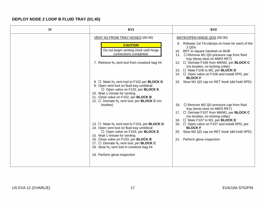
DEPLOY NODE 2 LOOP B FLUID TRAY (01:45)
US EVA 12 (CHARLIE) 17 EVA/10A STG/FIN
IV EV1 EV2
MATE/OPEN HINGE QDS (00:30)
9. Release 1st TA-clamps on hose for each of the 2 QDs
10. BRT to square handrail on BOB 11. � Remove M1 QD pressure cap from fluid
tray (temp stow on MWS RET) 12. � Demate F106 from M5/M2, per BLOCK C
(no booties, no locking collar) 13. � Mate F106 to M2, per BLOCK D 14. � Open valve on F106 and install SPD, per
BLOCK F 15. Stow M1 QD cap on RET hook (did hold SPD)
16. � Remove M2 QD pressure cap from fluid
tray (temp stow on MWS RET) 17. � Demate F107 from M6/M1, per BLOCK C
(no booties, no locking collar) 18. � Mate F107 to M1, per BLOCK D 19. � Open valve on F107 and install SPD, per
BLOCK F 20. Stow M2 QD cap on RET hook (did hold SPD)
21. Perform glove inspection
VENT N2 FROM TRAY HOSES (00:40)
7. Retrieve N2 vent tool from crewlock bag #4
8. � Mate N2 vent tool to F102 per BLOCK D 9. Open vent tool on fluid tray umbilical:
� Open valve on F102, per BLOCK E 10. Wait 1 minute for venting 11. Close valve on F102, per BLOCK B 12. � Demate N2 vent tool, per BLOCK C (no
booties) 13. � Mate N2 vent tool to F103, per BLOCK D 14. Open vent tool on fluid tray umbilical:
� Open valve on F103, per BLOCK E 15. Wait 1 minute for venting 16. Close valve on F103, per BLOCK B 17. � Demate N2 vent tool, per BLOCK C 18. Stow N2 vent tool in crewlock bag #4 19. Perform glove inspection
CAUTION
Do not begin venting clock until hinge connections completed.
DEPLOY NODE 2 LOOP B FLUID TRAY (01:45)
US EVA 12 (CHARLIE) 18 EVA/10A STG/FIN
IV EV1 EV2
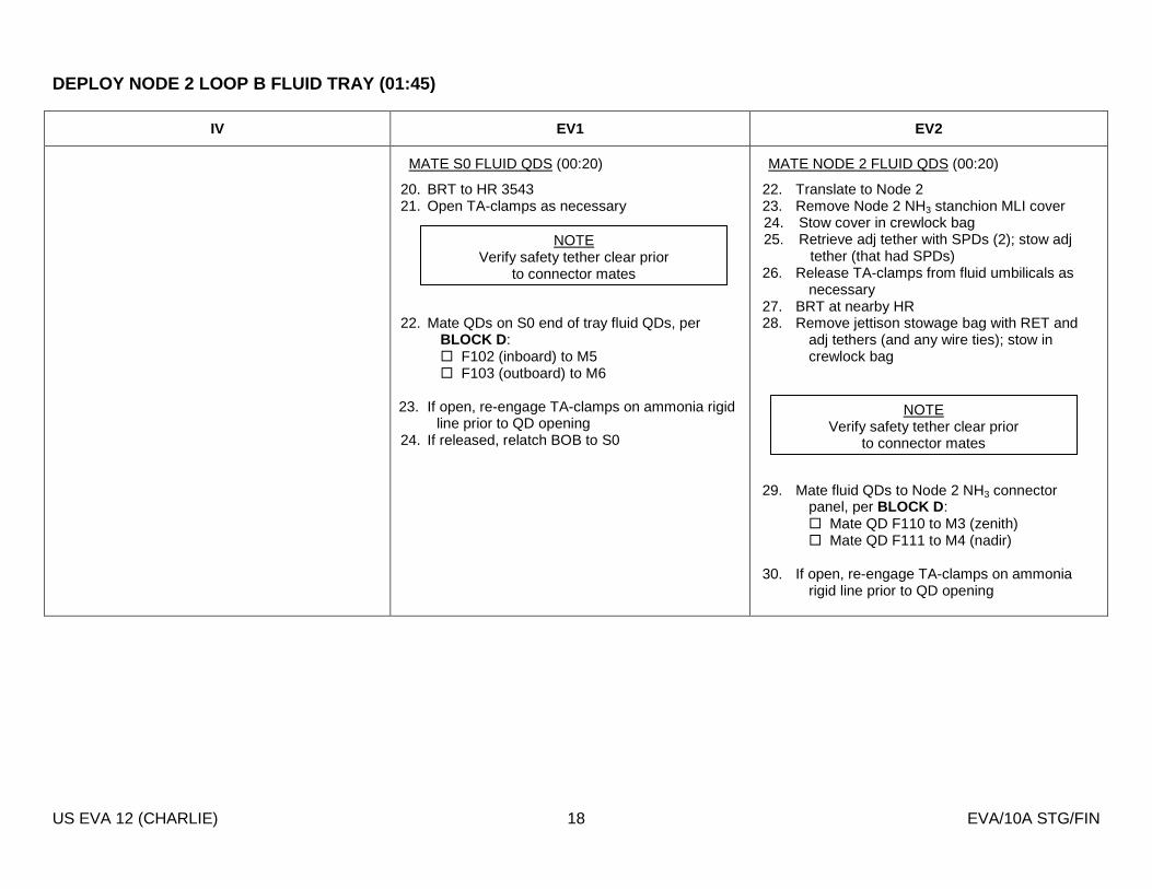
MATE S0 FLUID QDS (00:20)
20. BRT to HR 3543 21. Open TA-clamps as necessary
22. Mate QDs on S0 end of tray fluid QDs, per BLOCK D : � F102 (inboard) to M5 � F103 (outboard) to M6
23. If open, re-engage TA-clamps on ammonia rigid line prior to QD opening
24. If released, relatch BOB to S0
MATE NODE 2 FLUID QDS (00:20)
22. Translate to Node 2 23. Remove Node 2 NH3 stanchion MLI cover 24. Stow cover in crewlock bag 25. Retrieve adj tether with SPDs (2); stow adj
tether (that had SPDs) 26. Release TA-clamps from fluid umbilicals as
necessary 27. BRT at nearby HR 28. Remove jettison stowage bag with RET and
adj tethers (and any wire ties); stow in crewlock bag
29. Mate fluid QDs to Node 2 NH3 connector panel, per BLOCK D : � Mate QD F110 to M3 (zenith) � Mate QD F111 to M4 (nadir)
30. If open, re-engage TA-clamps on ammonia
rigid line prior to QD opening
NOTE Verify safety tether clear prior
to connector mates
NOTE Verify safety tether clear prior
to connector mates

DEPLOY NODE 2 LOOP B FLUID TRAY (01:45)
US EVA 12 (CHARLIE) 19 EVA/10A STG/FIN
IV EV1 EV2
1. IV: Verify with MCC-H, GO to open fluid QD
valves 2. IV: WVS, EV2 - center cam (Node 2 fluid QDs) 3. IV: WVS, EV1 - center cam (Shunt jumper
stowage & S0 fluid QDs)
OPEN S0 FLUID QDS (00:25)
Once QDs F110 and F111 open: 25. Open valves on S0 end of tray fluid QDs, per
BLOCK F : � Open QD F102/M5 (zenith/inboard) � Open QD F103/M6 (nadir/outboard)
26. Perform WVS closeout 27. Close any TA-clamps opened 28. If not already performed, insert fluid tray latch
PIP-pin into latch fitting 29. Close S0 MLI cover 30. Secure closeout cover flaps along underside of
upper tray blanket 31. Secure any remaining tray MLI as necessary 32. Perform glove inspection
CAUTION
Both Node 2 QDs must be opened prior to opening the S0 QDs
OPEN NODE 2 FLUID QDS (00:25)
On MCC GO: 31. Open valves on Node 2 tray fluid QDs, per
BLOCK F (no thermal bootie steps): � Open QD F110/M3 (zenith) � Open QD F111/M4 (nadir)
32. Perform WVS closeout 33. Close MLI around fluid QDs 34. Secure MLI around Bolt 10
a. Unwrap MLI “burrito” from zenith inboard portion of tray
b. Tuck aft corner of “burrito” MLI under Bolt 10 handle
35. Perform glove inspection
CAUTION
QDs with 90 deg bend are prone to galling. Ensure no side loads when opening valve.
Limit handling loads to <25 lb after opening valve.
NOTE Do not open valves until both
sides of fluid tray mated
NOTE Do not open valves until both
sides of fluid tray mated

AVIONICS UMBILICALS / FLUID LINE HEATER UMBILICALS
US EVA 12 (CHARLIE) 20 EVA/10A STG/FIN
IV EV1 EV2
1. IV: WVS, EV1 - center cam (heater lines) 2. IV: Notify MCC-H go for aliveness test 3. IV: WVS, EV2 - center cam (avionics umbilicals)
CONNECT FLUID LINE HEATER UMBILICALS (00:15)
1. On avionics tray, open 1 TA-clamp, release wire harness; close TA-clamp
2. Demate P680 and P681 from panel A230 3. At hinged end, remove connector caps from J680
and J681 4. Attach caps to panel A230 on avionics tray 5. Mate connectors to fluid tray receptacle panel
A151: � P680 to J680 � P681 to J681
6. Perform WVS closeout
7. Secure hinge blanket
- Wrap Velcro strap at hinge around zenith avionics panel (A149)
- Use short wire-tie to secure Velcro strap 8. Verify all fluid tray MLI secured 9. Translate to crewlock bag #1
10. Retrieve wire tie caddy; stow on self
CONNECT STBD AVIONICS UMBILICALS TO NODE 2 (00:30)
1. Stow adj tether (that had SPDs) in crewlock bag #1, if desired
2. Retrieve crewlock bag #1; stow on BRT 3. Translate to stbd side of Node 2 4. Temp stow crewlock bag #1; inform IV and
EV1 of location (EV1 will need wire-tie caddy)
5. Remove Node 2 avionics MLI cover 6. Translate to crewlock bag #1 7. Stow MLI cover 8. Retrieve avionics umbilicals from temp stow
location
9. Mate avionics umbilicals to Node 2:
� P674 to J674 (HX valves) � P673 to J673 � P671 to J671 � P672 to J672 � P670 to J670
10. Notify IV, all stbd avionics umbilicals mated 11. Perform WVS closeout
CAUTION
P674 powers the HX valve, and the inhibits to that connection will be
removed upon connection. Inform MCC if demate of P674 is required after
inhibits removed.

STBD CBM LAUNCH LOCKS / LAB-NODE 2 GAP SPANNER
US EVA 12 (CHARLIE) 21 EVA/10A STG/FIN
IV EV1 EV2
STBD CBM PETAL LAUNCH LOCKS (00:10)
Release Node 2 CBM petal launch locks: 1. Stbd
� Release two zenith latches: use HR 0353 � Release two fwd latches: use HR 0312 � Release two nadir latches: use HR 0354 � Release two aft latches: use HR 0341
Get-Aheads:
2. Port (0:15) � Release two aft latches � Release two zenith latches: use HR 0350 � Release two fwd latches: use HR 0321 � Release two nadir latches: use HR 0304
3. Nadir (00:15) � Release two aft latches � Release two zenith latches: use HR 0355 � Release two fwd latches: use HR 0308 � Release two nadir latches: use HR 0356
CAUTION
Both petal launch locks must be engaged to allow for translation on
the petal
INSTALL LAB/NODE 2 GAP SPANNER (00:25)
1. Retrieve gap spanner from crewlock bag 2. Donn over gloves 3. Translate to Lab/Node 2 port side primary
translation path 4. Install gap spanner located in trash bag:
� Lab handrail 0267 (nadir standoff) � Node 2 handrail 0364 (zenith
standoff) 5. Cinch gap spanner (90 deg rotation of
buckle) 6. Verify cam buckle rotates 90 degrees

CONNECT PMA2 REDUNDANT UMBILICALS (00:35)
US EVA 12 (CHARLIE) 22 EVA/10A STG/FIN
IV EV1 EV2
4. IV: WVS, EV1 - center cam (PMA2/Node 2 redundant umbilicals)
5. IV: WVS, EV1 - center cam (PMA2/Node 2 redundant umbilicals)
6. IV: Notify MCC-H go for aliveness test
CONNECT PMA2 REDUNDANT UMBILICALS (00:35)
1. Translate to PMA2 redundant umbilicals (ISS fwd/zenith side)
2. Release umbilicals from PMA2 temp stow location
3. Translate bundle to Node 2 connector panel (ISS stbd/zenith)
4. Temp secure umbilical bundle via wire tie to nearby handrail
5. Remove connector cover MLI; stow in trash bag
6. Verify safety tether clear 7. Connect umbilicals to Node 2 in any order:
BRT at HR 0359: � P609 / J609 � P614 / J614
� Perform WVS photo closeout � Slide thermal covers over zero-g
connectors at Node 2 connector panel BRT at HR 0360:
� P615 / J615 � P616 / J616
� Perform WVS photo closeout � Slide thermal covers over zero-g
connectors at Node 2 connector panel
8. Notify IV all PMA2/Node 2 redundant umbilicals mated
CAUTION 1. Avoid bend radii < 10 times cable diameter 2. Avoid pulling on cable during mate/demate
NOTE No inhibits required for PMA2 redundant
umbilical mates

CONNECT PMA2 REDUNDANT UMBILICALS (00:35)
US EVA 12 (CHARLIE) 23 EVA/10A STG/FIN
IV EV1 EV2
9. Secure umbilicals in clamps and with wire-ties to keep them secured with a low profile: � Node 2 handrail 0328 � Node 2 handrail 0315 � PMA2 handrail 0407
10. Verify all TA-clamps are closed

US EVA 11 CLEANUP/INGRESS (00:20)
US EVA 12 (CHARLIE) 24 EVA/10A STG/FIN
IV EV1 EV2
CLEANUP/INGRESS (00:20)
1. Perform glove inspection 2. Donn over gloves 3. Translate to crewlock bag #4 on S0 face 6 4. Retrieve bag; stow on BRT 5. Translate to VTE bag on S0 face 2 6. Retrieve MUT EE; temp stow on self 7. Attach VTE bag to crewlock bag #4 8. Verify no tools/hardware left on face 1
- Clear for MT/MBS translation 9. Translate to safety tether anchor points at top
of CETA spur 10. Verify EV2 anchored to airlock via waist tether 11. Unhook EV2’s safety tether from S0; connect to
own waist tether (daisy chain) - Engage crew hook slide lock - L (both) - Verify hook gate closed (both)
12. Unhook own safety tether from S0 handrail; temp stow on self
13. Perform tool inventory 14. Translate to zenith face of crewlock (VTE bag
stowage location) 15. Stow VTE bag via crewlock handrails 0552,
0553, 0557, and 0558 16. Unhook safety tether from airlock external
tether point 17. Hand in crewlock bag #4 to EV2 18. Ingress A/L 19. Remove SCU from stowage pouch 20. Remove DCM cover, Velcro to DCM 21. SCU->|<-DCM, √SCU locked 22. Water – OFF
CLEANUP/INGRESS (00:20)
1. Perform glove inspection 2. Retrieve crewlock bag #1 from temp stow on
Node 2; attach to BRT 3. Perform tool inventory 4. Translate to airlock
- Release fairlead and retrieve wire tie 5. Open A/L thermal cover 6. Attach waist tether (R) to airlock D-ring
extender - Engage crew hook slide lock - L - Verify hook gate closed
7. Stow crewlock bag #1 in airlock 8. Ingress airlock
9. Receive crewlock bag #4; stow 10. Give EV1 GO for ingress 11. Remove SCU from stowage pouch 12. Remove DCM cover, Velcro to DCM 13. SCU->|<-DCM, √SCU locked 14. Water – OFF

US EVA 11 CLEANUP/INGRESS (00:20)
US EVA 12 (CHARLIE) 25 EVA/10A STG/FIN
IV EV1 EV2
CAUTION
Do not close hatch until EMU WATER – OFF for 2 min
23. Close thermal cover, attach Velcro strap 24. Verify no hardware blocking hatch 25. EV Hatch – verify handle position per hatch
decal; close and lock
Go to PRE REPRESS portion of {CREWLOCK DEPRESS/REPRESS CUE CARD} (SODF:ISS EVA SYS: EVA PREP/POST)
CAUTION
Do not close hatch until EMU WATER – OFF for 2 min

GET-AHEAD: SSPTS CABLE DEPLOY (01:00)
US EVA 12 (CHARLIE) 26 EVA/10A STG/FIN
IV EV1 EV2
MCC-H 1. Verify inhibits are in place:
- DDCU LA1A or LA4A Converter - OFF - DDCU LA2A or LA3B Converter - OFF - RPCM LA1A4A_D RPC 03 - Open; CL CMD INH - RPCM LA2A3B_D RPC 01 - Open; CL CMD INH - RPCM Z13B_A RPC 02 - Open; CL CMD INH - RPCM Z14B_A RPC 02 - Open; CL CMD INH
W9302 (Between lab HRs 0271 and 0280)
1. Retrieve wire-tie caddy from crewlock bag #1 2. Follow EV1 and wire-tie cables to Node 2 HRs as
necessary to maintain a clean translation path
W9302 (zenith bag)
1. Disconnect straps on W9302 2. Tether bag for translation 3. Translate across Node 2 to PMA 2 4. Tether bag to Node 2 HRs 0352, 0353,
0359, 0360 5. Continue translating to PMA2 while
releasing cable from side A 6. Mate SSPTS J3A to PMA2 P3
W9303 (stbd-nadir bag)
3. Retrieve wire-tie caddy 4. Follow EV2 and wire-tie cables to Node 2 HRs as
necessary to maintain a clean translation path
W9303 (Between Lab HRs 0274 and 0281)
7. Disconnect straps on W9303 8. Release wire-tie at Lab HR 0272 9. Tether to bag for translation
10. Translate across Node 2 to PMA2 11. Tether bag to Node 2 HRs 0347, 0348,
0354, 0355 12. Continue translating to PMA2 while
releasing cable from side A 13. Mate SSPTS J16A to PMA2 P16

GET-AHEAD: RELOCATE APFR FOR 1E (00:15)
US EVA 12 (CHARLIE) 27 EVA/10A STG/FIN
IV EV1 EV2
RELOCATE APFR (00:15)
1. Translate to APFR on Lab WIF 6 (port side) 2. Retrieve APFR 3. Relocate to Node 2 WIF 14 (fwd endcone
nadir) 4. Configure APFR [6, PP, A, 6]
- Verify locking collar black-on-black - Perform pull test
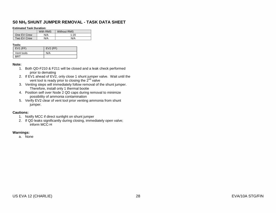
S0 NH3 SHUNT JUMPER REMOVAL - TASK DATA SHEET
US EVA 12 (CHARLIE) 28 EVA/10A STG/FIN
Estimated Task Duration: With RMS Without RMS One EV Crew N/A 1:20 Two EV Crew N/A N/A
Tools:
EV1 (FF) EV2 (FF)
Vent tools N/A BRT
Note:
1. Both QD-F210 & F211 will be closed and a leak check performed prior to demating
2. If EV1 ahead of EV2, only close 1 shunt jumper valve. Wait until the vent tool is ready prior to closing the 2nd valve
3. Venting steps will immediately follow removal of the shunt jumper. Therefore, install only 1 thermal bootie
4. Position self over Node 2 QD caps during removal to minimize possibility of ammonia contamination
5. Verify EV2 clear of vent tool prior venting ammonia from shunt jumper.
Cautions:
1. Notify MCC if direct sunlight on shunt jumper 2. If QD leaks significantly during closing, immediately open valve;
inform MCC-H Warnings:
a. None

S0 NH3 SHUNT JUMPER REMOVAL - TASK DATA SHEET
US EVA 12 (CHARLIE) 29 EVA/10A STG/FIN
Figure 1. S0 Port NH3 Shunt Jumper Overview
Figure 2. S0 Port NH3 Shunt Jumper (Shroud installe d)

RELOCATE & DEPLOY NODE 2 LOOP B FLUID TRAY – TASK D ATA SHEET
US EVA 12 (CHARLIE) 30 EVA/10A STG/FIN
Estimated Task Duration: With RMS Without RMS One EV Crew N/A N/A Two EV Crew N/A 0:30 (for tray relocate)
Tools:
EV3 (FF) EV4 (FF)
PGT PGT BRT BRT 7/16 (wobble) Socket-9 ext 7/16 (wobble) Socket-9 ext Russian Wire-Tie Russian Wire-Tie Jettison stowage bag Adj tethers (2)
EVA Fasteners:
Fastener Name
Label Head Size
Qty Ground Torque (ft-lb)
Recommended Release Torque (ft-lb)
Max Expected Release Torque
(ft-lb)
Failure Torque (ft-lb)
Recommended Install Torque
(ft-lb)
Min Install Torque (ft-lb)
Max Install Torque (ft-lb)
Turns (Clamp-up/Removal)
RPM
Fluid Umbilical Launch
Restraints
1 7/16 1 19.2 - 20.0
25.5 22.7 168.2 N/A N/A N/A 11 - 15 30
Fluid Umbilical Stanchion
Bolts
7 7/16 1 20.0 25.5 34.9 160 25.5 0.7 160 19.5 - 21.5 (Release from S0)
19 - 20.5 (Install on Lab)
30
Fluid Umbilical Stanchion
Bolts
10 7/16 1 N/A* 25.5 38.3 160 25.5 0.7 160 11.5 - 13.5 (Release from S0)
19 - 20.5 (Install on Lab)
30
* Bolt 10 has been release and re-installed on-orbit EVA Connectors:
Harness From To Conn Size
Function
W9104-P270 P680 (Dummy Panel) J680 (Panel A151) 15 Heater Power W9104-P272 P681 (Dummy Panel) J681 (Panel A151) 17 Heater Power P665 Lab Node 2 13 S0 VCSA Port 11 (f.o.) P664 Lab Node 2 25 S0 MDM to HX P660 Lab Node 2 25 S0 pwr to DDCU P661 Lab Node 2 25 S0 pwr to DDCU P662 Lab Node 2 25 S0 pwr to DDCU P663 Lab Node 2 25 S0 pwr to DDCU P101 Lab Node 2 15 PDGF to USL video (f.o.) P105 Lab Node 2 15 PDGF to USL video (f.o.) P104 Lab Node 2 25 So pwr to PDGF P103 Lab Node 2 15 PDGF to USL video (f.o.)

RELOCATE & DEPLOY NODE 2 LOOP B FLUID TRAY – TASK D ATA SHEET
US EVA 12 (CHARLIE) 31 EVA/10A STG/FIN
P102 Lab Node 2 25 S0 pwr to PDGF P674 Lab Node 2 25 S0 MDM to HX P702 Lab Node 2 25 S0 pwr to CAM P673 Lab Node 2 25 S0 pwr to DDCU P671 Lab Node 2 25 S0 pwr to DDCU P672 Lab Node 2 25 S0 pwr to DDCU P670 Lab Node 2 25 S0 pwr to DDCU
Connector Inhibits:
Task Inhibit P680 & P681 RPCM S01A_D RPC 2 - Open, Close Cmd Inhibit P101 None P102 RPCM S04B_C RPC3 & 4 P103 None P104 RPCM S03A_C RPC 1 & 2 P105 None P660 MBSU 1 RBI 10 P661 MBSU 1 RBI 11 P662 MBSU 4 RBI 2 P663 MBSU 4 RBI 10 P664 RPCM S02B_D RPC 2
RPCM S01A_D RPC 4 RPCM S01A_D RPC 5
P665 None P670 MBSU 2 RBI 3 P671 MBSU 2 RBI 10 P672 MBSU 3 RBI 3 P673 MBSU 3 RBI 2 P674 RPCM S01A_D RPC 2
RPCM S02B_D RPC 4 RPCM S02B_D RPC 5
Foot Restraints:
Task WIF APFR Setting Secure Loop B fluid tray onto Lab Lab WIF 11 1, QQ, A, 12
Note:
1. Verify safety tether stbd of BOB during deploy 2. Wait to insert fluid tray PIP pin until after EV2 has performed a fluid QD reach assessment at the BOB
Cautions:
1. No red band may be visible on waist tether prior to local tethering to gap spanner. Warnings:
1. None

RELOCATE & DEPLOY NODE 2 LOOP B FLUID TRAY – TASK D ATA SHEET
US EVA 12 (CHARLIE) 32 EVA/10A STG/FIN
Figure 3. Node 2 Port Fluid Tray
F111/M12/M4
F110/M11/M3
Bolt 12
Bolt 11 F103/M4/M6 F102/M3/M5 (opposite side)
F107/M6/M1 F106/M5/M2 (opposite side)
J681
J680
Bolt 7
Bolt 6
Bolt 5
Bolt 4
Bolt 3
Bolt 8
Bolt 2
Bolt 1
Bolt 9
Bolt 10
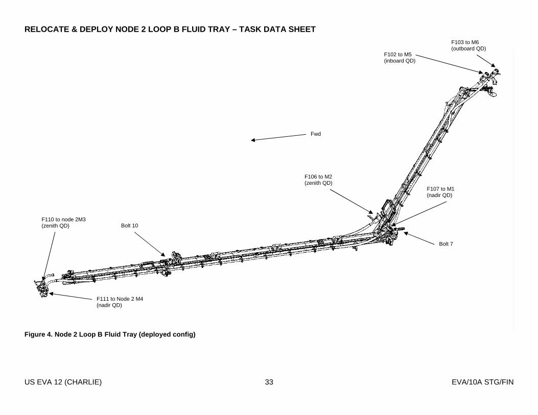
RELOCATE & DEPLOY NODE 2 LOOP B FLUID TRAY – TASK D ATA SHEET
US EVA 12 (CHARLIE) 33 EVA/10A STG/FIN
Figure 4. Node 2 Loop B Fluid Tray (deployed config )
Fwd
Bolt 10
Bolt 7
F106 to M2 (zenith QD)
F107 to M1 (nadir QD)
F111 to Node 2 M4 (nadir QD)
F110 to node 2M3 (zenith QD)
F103 to M6 (outboard QD)
F102 to M5 (inboard QD)

RELOCATE & DEPLOY NODE 2 LOOP B FLUID TRAY – TASK D ATA SHEET
US EVA 12 (CHARLIE) 34 EVA/10A STG/FIN
Figure 5. Node 2 Loop B Fluid Tray - S0 QDs
Figure 6. Node 2 Loop B Fluid Tray - Hinge QDs (dep loyed config)
Figure 7. Node 2 Loop B Fluid Tray - Node 2 QDs
Fwd
Fwd
Fwd
F103 to M6 (outboard QD)
F102 to M5 (inboard QD)
F106 to M2 (zenith QD)
F107 to M1 (nadir QD)
M6
J681 J680
F111 to Node 2 M4 (nadir QD)
F110 to node 2M3 (zenith QD)

RELOCATE & DEPLOY NODE 2 LOOP B FLUID TRAY – TASK D ATA SHEET
US EVA 12 (CHARLIE) 35 EVA/10A STG/FIN
Figure 8. Node 2 Fluid Tray Attachments on S0
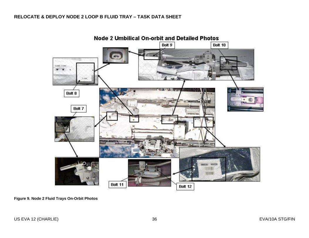
RELOCATE & DEPLOY NODE 2 LOOP B FLUID TRAY – TASK D ATA SHEET
US EVA 12 (CHARLIE) 36 EVA/10A STG/FIN
Figure 9. Node 2 Fluid Trays On-Orbit Photos

RELOCATE & DEPLOY NODE 2 LOOP B FLUID TRAY – TASK D ATA SHEET
US EVA 12 (CHARLIE) 37 EVA/10A STG/FIN
Figure 10. Loop B Fluid Tray relocation translation paths (fwd side of S0)
RELOCATE & DEPLOY NODE 2 LOOP B FLUID TRAY – TASK D ATA SHEET
US EVA 12 (CHARLIE) 38 EVA/10A STG/FIN
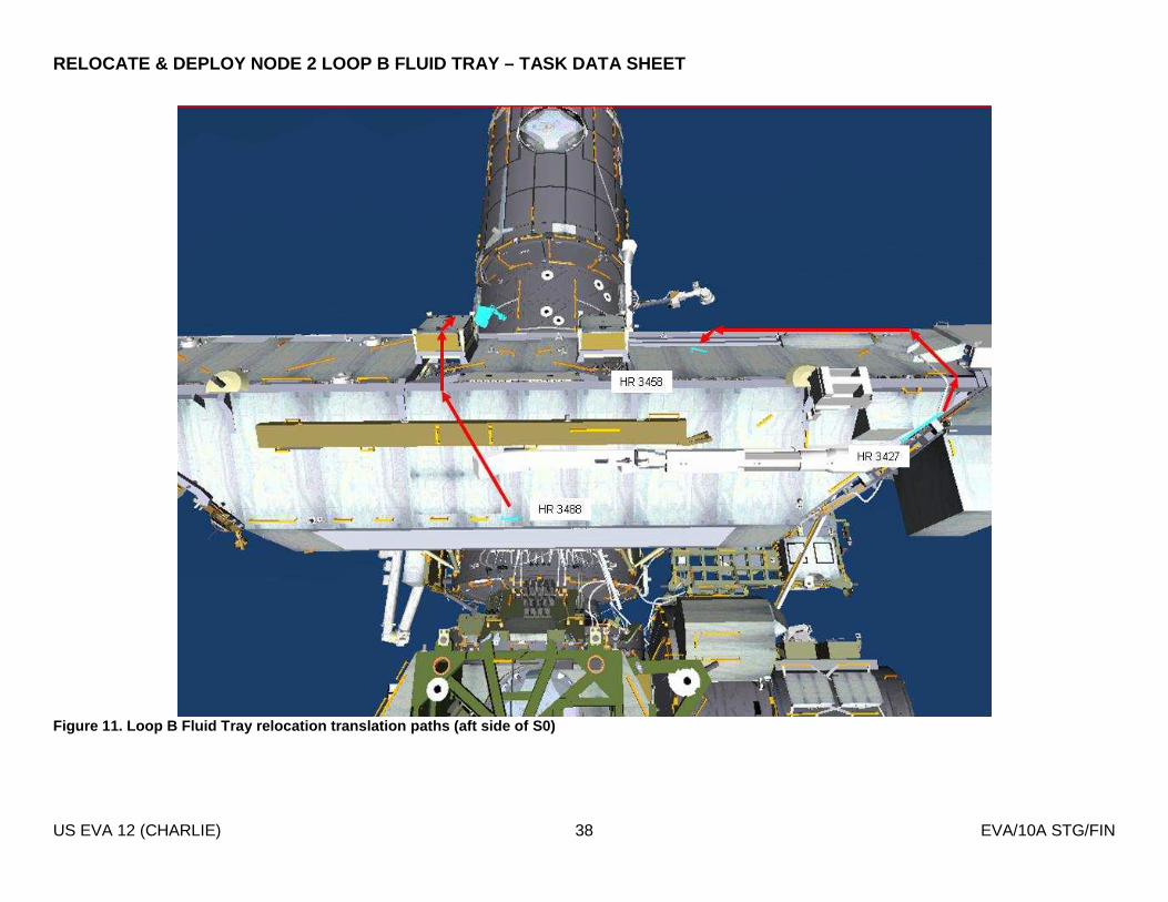
Figure 11. Loop B Fluid Tray relocation translation paths (aft side of S0)

NODE 2 LOOP B AVIONICS TRAY – TASK DATA SHEET
US EVA 12 (CHARLIE) 39 EVA/10A STG/FIN
Figure 12. Node 2 Aft Connectors (Avionics and Flui d)
J665 - J661
J663 - J102
M2 - J673
J674 - J670
NODE 2 LOOP B AVIONICS TRAY – TASK DATA SHEET
US EVA 12 (CHARLIE) 40 EVA/10A STG/FIN
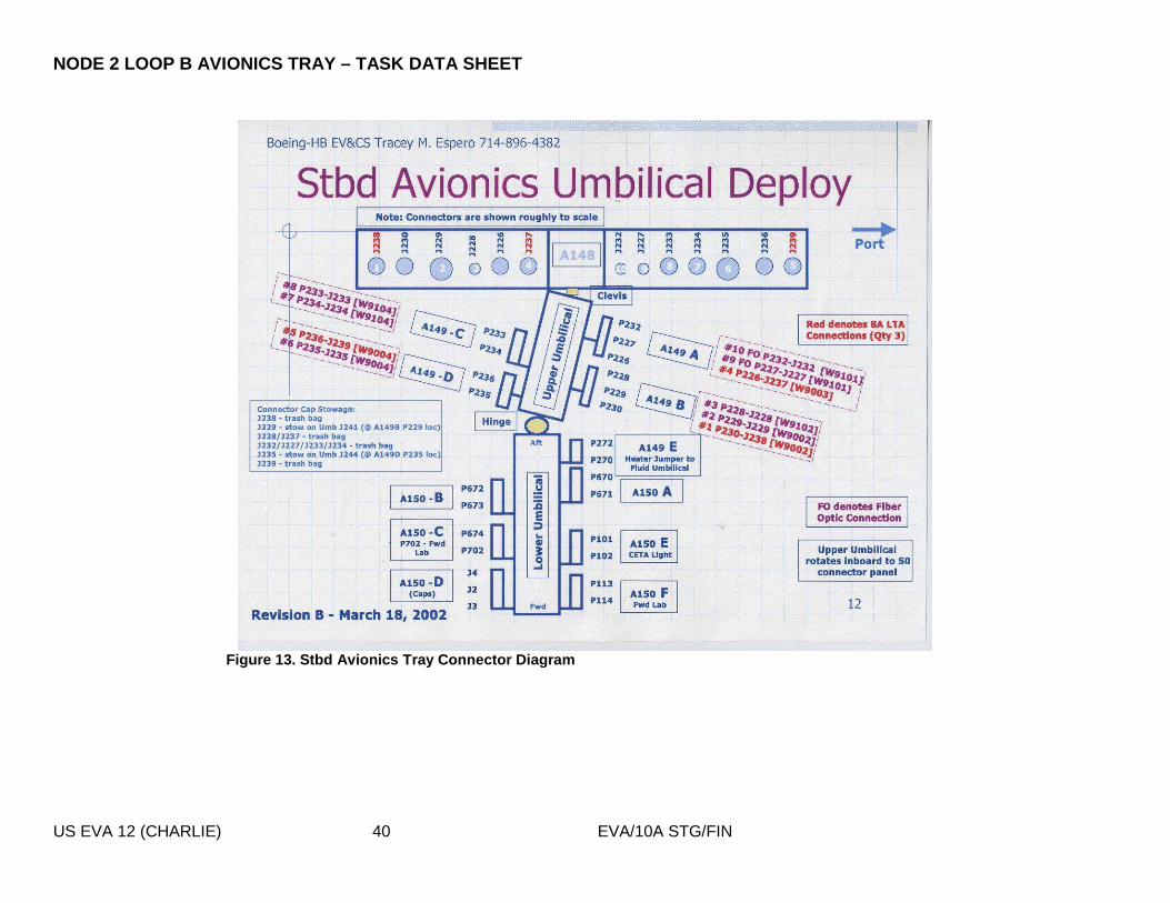
Figure 13. Stbd Avionics Tray Connector Diagram

PMA2-TO-NODE 2 UMBILICALS - TASK DATA SHEET
US EVA 12 (CHARLIE) 41 EVA/10A STG/FIN
Estimated Task Duration: With RMS Without RMS One EV Crew N/A 0:35 (Primary)
0:35 (Redundant) Two EV Crew N/A N/A
Tools:
EV1 (FF) EV2 (FF)
BRT BRT Wire Ties Wire Ties
EVA Connectors:
Harness From To Conn Size Function P609 (R) PMA 2 Node 2 25 None P610 (P) PMA 2 Node 2 25 None P611 (P) PMA 2 Node 2 17 Data – RTDs, GNC Moding P612 (P) PMA 2 Node 2 21 Shell Heaters P613 (P) PMA 2 Node 2 15 Data – 1553 A, Video P614 (R) PMA 2 Node 2 15 Data – 1553 B, Video P615 (R) PMA 2 Node 2 15 None P616 (R) PMA 2 Node 2 15 Data – Audio
Connector Inhibits:
Task Inhibit P609 (R) None P610 (P) None P611 (P) None P612 (P) DDCU LA1A OR LA4A CONVERTER - OFF
RPCM N21A4A_B RPC 1-5, 12-16 - OPEN, CL CMD INH P613 (P) None P614 (R) None P615 (R) None P616 (R) None
Notes: 1. Verify pin and EMI band integrity; verify connector free of FOD 2. No inhibits required for PMA2 redundant umbilical mates
Cautions:
1. Avoid bend radii < 10 times cable diameter 2. Avoid pulling on cable during mate/demate 3. Bail linkage on P613 is broken and will require modified technique
Warnings: 1. None

PMA2-TO-NODE 2 UMBILICALS - TASK DATA SHEET
US EVA 12 (CHARLIE) 42 EVA/10A STG/FIN
Figure 14. Port/Zenith Node 2 Connector Panel Figur e 15. Stbd/Zenith Node 2 Connector Panel

PMA2-TO-NODE 2 UMBILICALS - TASK DATA SHEET
US EVA 12 (CHARLIE) 43 EVA/10A STG/FIN
Figure 16. Node 2 connectors
GET-AHEAD: SSPTS DEPLOY – TASK DATA SHEET
US EVA 12 (CHARLIE) 44 EVA/10A STG/FIN
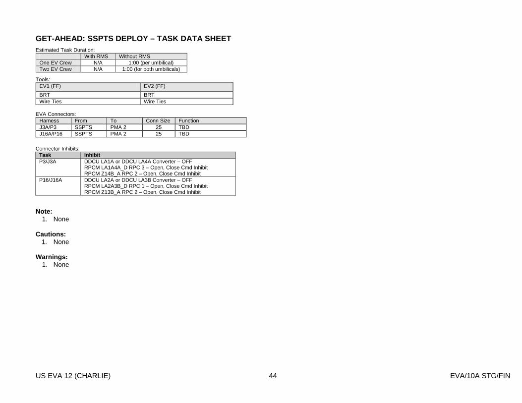
Estimated Task Duration: With RMS Without RMS One EV Crew N/A 1:00 (per umbilical) Two EV Crew N/A 1:00 (for both umbilicals)
Tools:
EV1 (FF) EV2 (FF)
BRT BRT Wire Ties Wire Ties
EVA Connectors:
Harness From To Conn Size Function J3A/P3 SSPTS PMA 2 25 TBD J16A/P16 SSPTS PMA 2 25 TBD
Connector Inhibits:
Task Inhibit P3/J3A DDCU LA1A or DDCU LA4A Converter – OFF
RPCM LA1A4A_D RPC 3 – Open, Close Cmd Inhibit RPCM Z14B_A RPC 2 – Open, Close Cmd Inhibit
P16/J16A DDCU LA2A or DDCU LA3B Converter – OFF RPCM LA2A3B_D RPC 1 – Open, Close Cmd Inhibit RPCM Z13B_A RPC 2 – Open, Close Cmd Inhibit
Note:
1. None Cautions:
1. None Warnings:
1. None

GET-AHEAD: SSPTS DEPLOY – TASK DATA SHEET
US EVA 12 (CHARLIE) 45 EVA/10A STG/FIN
Figure 17. SSPTS cables routed across Node 2
W9302
W9303
Cable Bag W9302 Deployment Location
Cable Bag W9303 Deployment Location

GET-AHEAD: SSPTS DEPLOY – TASK DATA SHEET
US EVA 12 (CHARLIE) 46 EVA/10A STG/FIN
Figure 18. SSPTS cable routing
HR 0274
HR 0273
HR 0275
HR 0374
HR 0372
HR 0342
HR 0334
HR 0332
J114A
J113A
P114
P113
8A LTA
Cable
W9303
W9302

GET-AHEAD: SSPTS DEPLOY – TASK DATA SHEET
US EVA 12 (CHARLIE) 47 EVA/10A STG/FIN
Figure 19. SSPTS cable routing and wire-tie locatio ns
W9303
W9302
HR 0361
HR 0354 HR
0347
HR 0342
HR 0334
HR 0360
HR 0353
HR 0346
HR 0332

GET-AHEAD: SSPTS DEPLOY – TASK DATA SHEET
US EVA 12 (CHARLIE) 48 EVA/10A STG/FIN
Figure 20. SSPTS cable routing and wire-tie locatio ns for fwd end stbd side
HR 0353
HR 0360 HR
0328
HR 0354
HR 0361
HR 0312
HR 0329
J16A
PMA 2 Panel A3
P16 TA
Clamp
W9303
W9302

GET-AHEAD: SSPTS DEPLOY – TASK DATA SHEET
US EVA 12 (CHARLIE) 49 EVA/10A STG/FIN
Figure 21. SSPTS cable routing and wire-tie locatio ns on fwd end port side
J3A
PMA 2 Panel
A2
P3
TA Clamp

GET-AHEAD: SSPTS DEPLOY – TASK DATA SHEET
US EVA 12 (CHARLIE) 50 EVA/10A STG/FIN
Figure 22. SSPTS cable routing and connections on P MA2
Port view of PMA 2 Zenith
Fwd
W9302
J3a
J3 on existing cable to Node 2
P3 on existing cable to APAS
Zenith
Fwd
Starboard view of PMA 2
P16 on existing cable
to APAS
J16 on existing cable to Node 2
J16a
W9302
Panel A3
W9303
Panel A2

POST US EVA 12 (CHARLIE) TOOL CONFIG
US EVA 12 (CHARLIE) 51 EVA/10A STG/FIN
EV1 EV2 AIRLOCK CONFIG � MWS � MWS � Staging Bag � BRT (L) � BRT (L) � Fuse Tether (1) � RET (eq-eq) � RETs (eq-eq) � Connector Cleaner Tool Kit � Wire Ties � Wire Ties � Connector Pin Straightener � Short (1) � Short (3) � Probe � Long (1) � Long (2) � Velcro/Tape Caddy � T-Bar � T-Bar � Pry Bar � RET (eq-eq) (2) � RET (eq-eq) (2) � Fuse Tether (1) � RET (eq-eq) w/ PIP pin (1) � RET (eq-eq) w/ PIP pin (1) � PGT (spare) S/N _________ � Adj Tether (1) � Wire Ties (2) � PGT Battery S/N _________ � Wire Ties (2) � Small Trash Bag � Wire Tie Caddy (w/ 9 wire ties) � Small Trash Bag � QD pressure caps (2, M1 and M2) � Vise Grips � Socket Caddy � RET (eq-eq) (2) � EVA Ratchet � 7/16 Socket - 9 ext (w/ decoration) � Over-gloves (2) � Cheater Bar � 7/16 Socket - 2-in ext � Socket Caddy � RET (eq-eq) (2) � 7/16 Socket - 9 ext (w/ decoration) � Over-gloves (2) � Swing Arm (R) � IV Bag � Wire Tie Caddy (1) � PGT [MTL 30.5] S/N _______ � Contamination Detection Kit � Swing Arm (R) � PGT Battery S/N _______ � Gold Salt Coupon (6) � PGT [MTL 30.5] S/N _______ � RET (eq-eq) � Color Chart (2) � PGT Battery S/N _______ � Waist Tether (R & L) � ISS Contamination Sampler (2) � RET (eq-eq) � D-ring Extender (R & L) � Shuttle Contamination Sampler (2) � Waist Tether (R & L) � SAFER � Nitrogen Dioxide Draeger Tube (6) � D-ring Extender (R & L) � WVS � Ammonia Draeger Tube (6) � SAFER � Safety Tether 85’ � DCM Plug (2) - SAFER Hard Mount � WVS � GP Caddy (2) � Safety Tether 85’ � Thermal Mittens (2 pr) � Crewlock Bag #1 � EVA Ratchet � w/ RET (Lg-sm) � Socket Caddy � Crewlock Bag #4 (QD Tools) � Adj Equip Tether (bag exterior to secure bag at worksite) � 1/2 x 8-in socket (IV Hatch) � w/ RET (Lg-sm) � Adj Equip Tether (on internal RET, was for SPDs) � 7/16 x 6-in socket (backup) � Adj Equip Tether (bag exterior) � QD pressure caps (2, M1 and M2) � � 1” QD Release Tool (on internal RET) � Adj Equip Tether (on internal RET, was for SPDs) � D-ring extender on EVA hatch D-ring � 1” QD Bail Drive Lever (on internal RET) � Digital camera w/ RET � RET (1 to internal tether point) � RET � Fuse Tether � N2 Vent Tool � to Adj Equip Tether � Long duration tie-down tethers (4) � RET (2 for SPDs - to internal tether points) � Caps (2) � RET (1 for vent tool - to ext bag handle) � Node 2 MLI (ammonia) � RET (1 to internal tether point) � Node 2 MLI (avionics) � Button depress tool (1-in) � Adj Equip (2 - for handling on ext bag handle) � RET (1 to internal tether point) � Wire-tie (used to secure fluid QDs during relocate) � AKT (1-in) � Jettison Stowage Bag � RET (on drawstring, bundled in bag) � Adj Equip Tether - for handling (to RET, bundled in bag) � Adj Equip Tether (for handling) (to adj, around bundle)