US Airways Flight 1549 A320-214 N106US Landing in the ... the conclusion that for the A320 aircraft...
54
Page 1 of 54 Submission to the National Transportation Safety Board For the US Airways Flight 1549 A320-214 N106US Landing in the Hudson River Weehawken, New Jersey January 15 2009 Accident Investigation AIRBUS S.A.S
Transcript of US Airways Flight 1549 A320-214 N106US Landing in the ... the conclusion that for the A320 aircraft...

Page 1 of 54
Submission to the
National Transportation Safety Board
For the
US Airways Flight 1549 A320-214 N106US
Landing in the Hudson River Weehawken, New Jersey
January 15 2009
Accident Investigation
AIRBUS S.A.S

Page 2 of 54
INTRODUCTION
In accordance with the NTSB rules, Airbus submits this report on the investigation of the accident involving US Airways Flight 1549 emergency landing on water on January 15, 2009 during a scheduled flight from New York/La Guardia Airport to Charlotte.
The aircraft involved was an Airbus A320-214, Manufacturer Serial
Number MSN: 1044 equipped with CFM 56-5B4 engines. All 155 persons on board safely evacuated the aircraft. 5 persons were
reported seriously injured. According to ICAO Annex 13, Airbus is acting as an advisor to the
Bureau d’Enquêtes et d’Analyses pour la Sécurité de l’Aviation Civile (–B.E.A-) in this investigation.

Page 3 of 54
Submission Abstract
• On January 15 2009, Flight 1549 experienced multiple bird strikes impacting both engines, soon after take-off. This occurred while in clean configuration at approximately 3000ft.
• This multiple bird strikes led to a loss of thrust on both engines to the extent
that continued level flight could not be maintained. However the N2 of engine number 1 was still at a level sufficient for its associated electrical generator (–IDG-) to remain on-line.
• It was confirmed by the Smithsonian Institute that the birds involved were
“Canada Geese” with an average weight far above the maximum certified weight for CFM 56-5B engines(between 5.8 and 10.7 lbs versus 4 lbs considered during certification for a single large bird ingestion). However the extent of the engines failures was contained and the engines kept delivering some electrical and hydraulic power.
• The crew immediately started the APU, and followed the QRH “ENG
DUAL FAILURE” procedure.
• After reviewing their options (including those proposed by ATC), for a possible emergency return to La Guardia or a diversion to Teterboro, the crew decided to perform an emergency landing on the Hudson River.
• During the remaining portion of the flight, the Aircraft remained in Normal
Law, and on occasion was flown within the alpha protection range. Notably from approximately 150 ft down to the water impact the Aircraft was in slats/flaps configuration 2. During this time period the Aircraft was in the alpha protection mode which allowed the flight crew to remain focused on their priorities, conversely if the Aircraft had been a non fly-by-wire aircraft, the flight crew would have had to fly in and out of the stick shaker to maintain the desired descent profile.
• The QRH “ENG DUAL FAILURE” procedure has been designed for events occurring at high altitude, with enough time to go through the complete procedure. It is not designed for emergency situation such as the one experienced during this event.
• The cockpit crew had insufficient time to complete the “ENG DUAL
FAILURE” check-list

Page 4 of 54
• All water entries studies performed either by NACA or later by IMFL lead to the conclusion that for the A320 aircraft on shallow water, the optimum configuration is to have:
- Landing gear retracted - Full slats/flaps configuration for minimum speed - Pitch around 11° - Slope around -0.5°
These data translate into a 3.5 ft/sec vertical speed at water impact. It also shows that in case of water impact with an aircraft pitch below ≈ 8°, or above ≈15° major airframe structural breakage is expected.
• In Flight 1549, the Aircraft’s energy just prior to water impact was
insufficient to significantly decrease the vertical speed during flare, leading to a water impact at around 13ft/s. Despite this rate of descent at water impact, the extent of aircraft damages did not prevent a safe evacuation for all persons on board. Aircraft pitch at water impact was close to the optimum recommended value.
• The vertical speed at water impact led to significant deformation and
damage to the lower portion of the Aircraft’s aft fuselage.
• The Aircraft’s cabin interior remained in relatively good condition, and evacuation took place using both forward doors and overwing emergency exits. Both aft doors were not used due to water entering the cabin in this area.
• Although not an “Extended Over Water” flight (EOW), the Aircraft was
“EOW” equipped. The availability of forward slide rafts most probably contributed to the successful emergency evacuation. Eventually, all 150 passengers and 5 crew members safely evacuated the Aircraft and were rescued by various boats.
• Airbus is currently reviewing how to further support crews facing an
emergency situation at low altitude.
Page 5 of 54
CONTENTS
Page 1 Factual information 7
1.1 History of Flight 7 1.2 Injuries to persons 8 1.3 Damage to the aircraft 9 1.4 Other damage 11 1.5 Personnel information 11 1.6 Airplane information 11
1.6.1 The CFM 56-5B4 engines, and associated systems 11 1.6.2 Hydraulic power 16 1.6.3 The A320 Flight envelope protection 16 1.6.4 The “Ditching” function 17 1.6.5 The A320 Cabin 17
1.6.5.1 Cabin Intercommunications Data System (CIDS) 17 1.6.5.2 Emergency lighting 18 1.6.5.3 Seats 19 1.6.5.4 Overhead Stowage Compartments (OHSC) 20
1.6.6 Emergency equipment 20 1.6.6.1 Slide rafts and overwing slides 20 1.6.6.2 Life lines 23 1.6.6.3 Survival kits 23 1.6.6.4 Life vests / cushions 24 1.6.6.5 Safety cards 24 1.6.6.6 Evacuation 24
1.7 Meteorological Information 25 1.8 Aids to Navigation 25 1.9 Communications 25
1.9.1 Flight deck - cabin communication 25 1.9.2 Cabin to cabin communication 25
1.10 Airport Information 26 1.11 Air Traffic Control Information 26 1.12 Flight Recorders 26
1.12.1 DFDR 26 1.12.2 CVR 28
1.13 Wreckage and Impact Information 28 1.13.1 Cargo doors 28 1.13.2 Cabin damage 28
1.14 Medical and Pathological Information 29 1.15 Fire 29

Page 6 of 54
1.16 Survival Aspects 30 1.17 Tests and Research 30
1.17.1 Airframe structure 30 1.17.2 Passengers doors investigation 31 1.17.3 Cargo doors 31 1.17.4 Flight handling qualities 32
1.18 Organizational and Management Information 32 1.19 Additional Information 32
1.19.1. Certification requirements for transport aircraft 32 1.19.1.1 Engine birds ingestion 32 1.19.1.2 Event classification versus certification criteria 32
2 Analysis 36
2.1 Reconstruction of aircraft performance from DFDR data 36 2.1.1 Overall flight 36 2.1.2 Engines behaviour 36 2.1.3 Water impact 44
2.2 Operational aspects 45 2.3 Survival aspects 46
2.3.1 Cabin integrity 46 2.3.2 Evacuation means 47 2.3.3 Passenger doors 48 2.3.4 Cargo doors 49
3 Conclusions 52 3.1 Findings 52 3.2 Probable Cause 53
4 Recommendations 54 4.1 Previously issued recommendations 54
4.1.1 Pre-flight briefing 54 4.1.2 ATC identification of aircraft in emergency 54
4.2 New recommendations 54 4.2.1 Crew training 54 4.2.2 Emergency equipment briefing 54 4.2.3 Safety cards 54

1 Factual information 1.1 History of Flight On January 15 2009, about 3:27pm eastern standard time, US Airways flight 1549 (Flight 1549) operated with Airbus A320, Manufacturer Serial Number (MSN) 1044, FAA registration N106US (the Aircraft) made an emergency water landing in the Hudson river about 5 minutes after take-off from New-York La Guardia airport. Flight 1549 was a regularly scheduled flight to Charlotte with 2 flight crew members, 3 flight attendants, and 150 passengers. About 1.5 minutes after take-off, at a corrected altitude of 3056ft, the Aircraft encountered multiple bird strikes leading to a loss of thrust on both engines (CFM56-5B). About 3.5 minutes later the crew performed an emergency landing in the Hudson River. Throughout the complete flight, the Aircraft remained in normal control law All 155 persons on board evacuated the Aircraft safely. 4 passengers and 1 flight attendant were reported seriously injured.
Page 7 of 54
Page 8 of 54
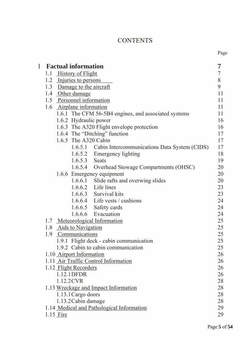
1.2 Injuries to persons
The following information is extracted from the NTSB factual report and contains injury information from medical records and self-reported injuries from interviews:
Injuries Flight Crew
Cabin Crew Passengers Other Total
Fatal 0 0 0 0 0 Serious 0 1 4 0 5 Minor 0 0 95 0 95 None 2 2 51 0 55 Total 2 3 150 0 155
Injury table
From the same report, two of the passengers were transported to the hospital and one cabin attendant sustained serious injuries. One of the passengers sustained a fractured xiphoid process on his sternum while a passenger suffered hypothermia and was not released from the hospital until 04:45 pm on January 17, 2009. CFR § 830.2 defines “serious injury” as “any injury which: (1) requires hospitalization for more than 48 hours, commencing within 7 days
from the date of the injury was received; (2) results in a fracture of any bone (except simple fractures of the fingers,
toes, or nose); (3) severe hemorrhages, nerve, muscle, or tendon damage; (4) involves any internal organ; (5) involves second- or third-degree burns, or any burns affecting more than 5
percent of the body surface.” The mentioned cabin attendant sustained a complicated, 12cm long, 5cm deep, lower left leg laceration that required surgery to close. The report also states that two passengers were not initially transported to a hospital but reported serious injuries during interviews. Both were requested to provide medical records to substantiate their injuries and complied. One passenger sustained a fractured left shoulder while another passenger sustained a fractured right shoulder.
Airbus did not have access to any of the medical records.

1.3 Damage to the Aircraft
During the rescue operation, the Aircraft suffered multiple damages due to impacts from rescue and later towing boats.
For example, the following pictures clearly show that the left wing outboard slat and flap were still present after the emergency landing on water, while it was later completely destroyed after the towing operations.
Page 9 of 54
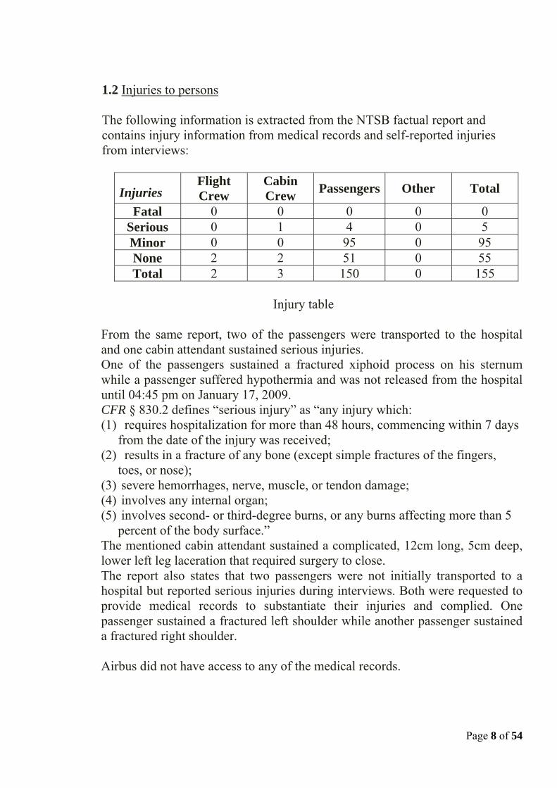
The Aircraft was then towed by tug boat to the Battery Park Wharf just north of the North Cove Ferry Terminal. The Aircraft was moored with left wing, left overwing slide and portions of the forward fuselage and the vertical stabilizer initially visible above the surface of the river. The right wing was submerged below the Battery Park Esplanade. Two days after the event, prior to the Aircraft’s recovery from the river it had become completely submerged with none of the Aircraft structure being visible from the esplanade. The airplane was recovered using a barge -mounted crane and placed on the deck of another barge. The Aircraft was subsequently relocated to a marine salvage company’s facility in Jersey City, New Jersey for examination and documentation. The right engine remained attached to the wing and the left engine separated from the wing during the unplanned emergency water landing. The horizontal and vertical stabilizers and portions of the movable control surfaces remained attached to the Aircraft. The nose and main landing gears remained retracted and attached to the Aircraft. The fuselage and wings experienced multiple bird strikes, and sustained damage during the unplanned water landing and recovery phase.
Page 10 of 54

Damages due to birds impacts are documented in NTSB factual report DCA09MA0026, together with many other damages induced by the rescue, towing and recovery operations. The damages which occurred during the Aircraft emergency landing on water are documented in NTSB factual report DCA09MA0026 Addendum 1.
1.4 Other damage
Airbus has not been made aware of any other damage.
1.5 Personnel information Information concerning the crew are detailed in NTSB Operations/Human Performance Group Chairmen Factual Report.
1.6 Airplane information
1.6.1 The CFM 56-5B4 engines and associated systems
With respect to engine indication parameters visible to the flight crew the relevant certification regulations are JAR25.1305 and FAR25.1305 (applicable at the time of the Aircraft’s certification).
Page 11 of 54

Page 12 of 54

The upper ECAM displays permanently the following main engine parameters:
• Thrust control parameter (% N1) • N1 actual • N1 command • N1 TLA (Throttle Lever Angle) corresponding to the lever
position • N1 limit for actual thrust rating • N1 max • Max permissible N1 • Exhaust Gas Temperature (EGT) • HP rotor speed (% N2) • Fuel flow per engine • Thrust limit mode
Page 13 of 54
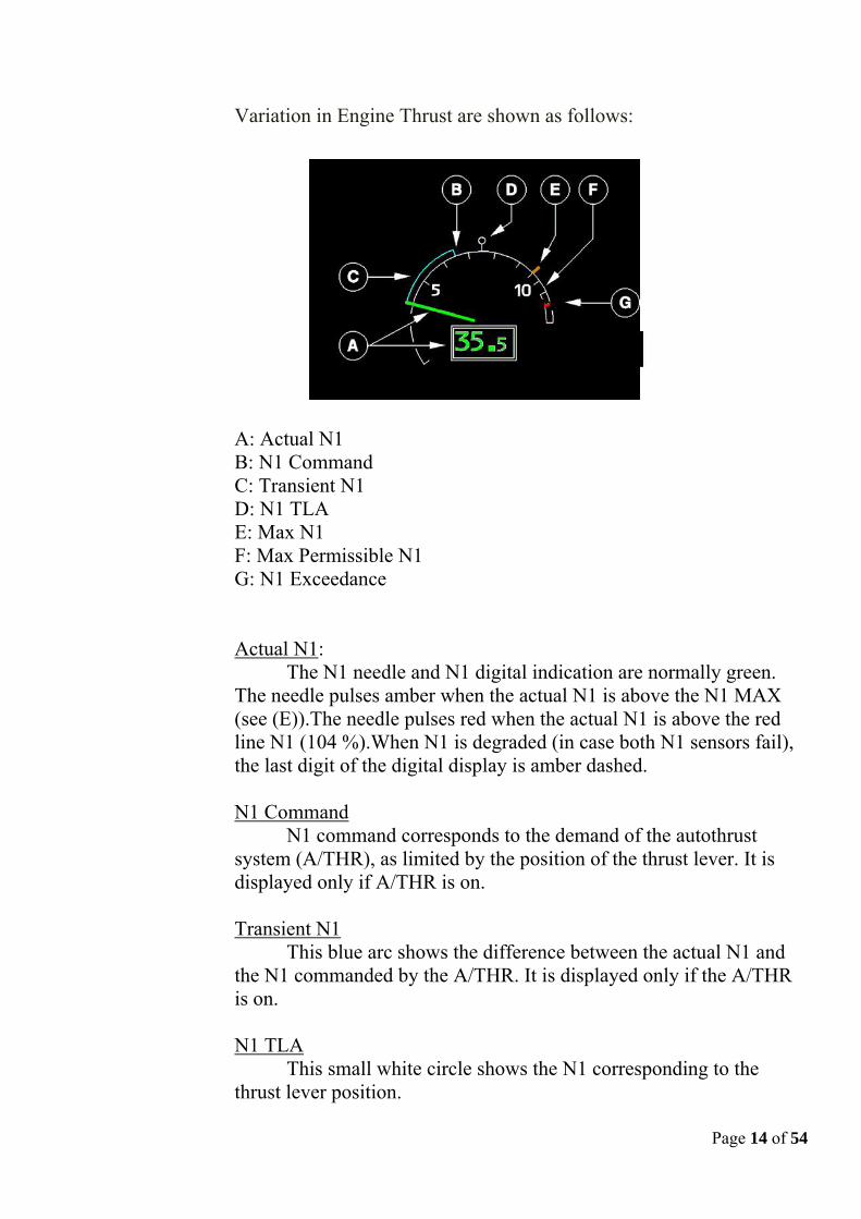
Variation in Engine Thrust are shown as follows:
A: Actual N1 B: N1 Command C: Transient N1 D: N1 TLA E: Max N1 F: Max Permissible N1 G: N1 Exceedance
Actual N1: The N1 needle and N1 digital indication are normally green.
The needle pulses amber when the actual N1 is above the N1 MAX (see (E)).The needle pulses red when the actual N1 is above the red line N1 (104 %).When N1 is degraded (in case both N1 sensors fail), the last digit of the digital display is amber dashed.
N1 Command
N1 command corresponds to the demand of the autothrust system (A/THR), as limited by the position of the thrust lever. It is displayed only if A/THR is on.
Transient N1
This blue arc shows the difference between the actual N1 and the N1 commanded by the A/THR. It is displayed only if the A/THR is on. N1 TLA
Page 14 of 54
This small white circle shows the N1 corresponding to the thrust lever position.
Page 15 of 54
Max N1 This amber index shows the N1 the engine would produce with
the thrust lever all the way forward. Max permissible N1
This red arc, showing the prohibited or "redline" area of operation, begins at 104 %. N1 exceedance
If N1 exceeds 104 % during a flight, this red mark appears and remains at the highest N1 attained. It disappears after a new start on the ground or after maintenance action through the MCDU.
Engine Failure Indications:
In addition to the principal engine parameters displayed to the
flight crew the Flight Warning Computer system has the ability to display the following warnings and cautions based upon the following criteria and dependent upon flight phase:
- ENG X FAIL Set when N2 drops below 50 % (not the case on engine 1 during the event) and Master Lever is ‘On’. - ENG X STALL The Airbus Single Aisle family fleet fitted with CFM engines has no engine stall annunciation while the engine is above Idle. This caution is set when N2 is above 50% and below Idle (a condition that did not occur on engine number 1 during the event).
- ENG X START FAULT For this caution to be set, the engine needs to be in a start sequence
- ENG X START VALVE FAULT For this caution to be set, the engine needs to be in a start sequence.
- ENG X SHUTDOWN set when the Master Lever is set to off or the
Fire Handle is pulled.
- ENG DUAL FAILURE Set when both’N2 on both engines are below 50%.
It is important to note that the electrical generation provided by the engines through the IDG’s remains on line as long as its respective engine N2 remains above 56.3 %. During this event, the engine N°1 IDG remained on-line up to the time of the engine N°1 re-start attempt. From the APU Master Switch selection to ON and the APU start, it normally takes approximately 1 minute for the APU Electrical generation to become available. The DFDR data, confirms that the APU electrical power was already available at the time of the engine N°1 re-start attempt took place, thus allowing the aircraft to remain in Normal law, and all displays to remain available to the crew.
1.6.2 Hydraulic power The DFDR data shows that during the complete flight, the Aircraft always had sufficient hydraulic power. There was no “low press warning” recorded on any of the three hydraulic circuits.
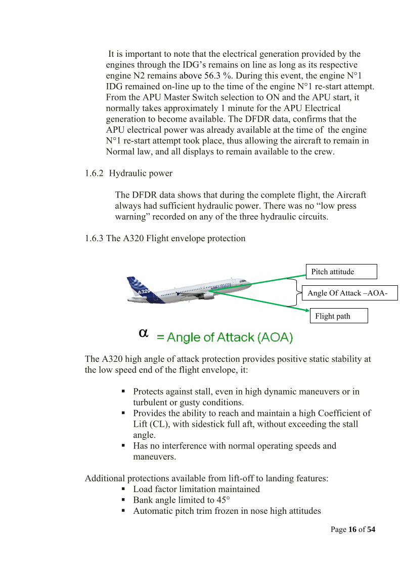
1.6.3 The A320 Flight envelope protection
α
Angle Of Attack –AOA-
Flight path
Pitch attitude
The A320 high angle of attack protection provides positive static stability at the low speed end of the flight envelope, it:
Protects against stall, even in high dynamic maneuvers or in turbulent or gusty conditions.
Provides the ability to reach and maintain a high Coefficient of Lift (CL), with sidestick full aft, without exceeding the stall angle.
Has no interference with normal operating speeds and maneuvers.
Additional protections available from lift-off to landing features:
Load factor limitation maintained Bank angle limited to 45° Automatic pitch trim frozen in nose high attitudes
Page 16 of 54

1.6.4 The ditching function As called for in the relevant procedures, pressing the “DITCHING” pushbutton on the CABIN PRESS control panel closes the outflow valve, the emergency ram air inlet, the avionics ventilation inlet and extract valves, and the pack flow control valves. 1.6.5 The A320 Cabin
1.6.5.1Cabin Intercommunications Data System (CIDS)
The Cabin Intercommunications Data System (CIDS) is used in order to operate, control and monitor various cabin functions, including the cabin and flight crew interphone system. Each CIDS is customized to the operator’s choices through the Cabin Assignment Module (CAM).
The interphone system allows communication within the cabin, and from the cockpit to the cabin, using handsets. The handset layout depends on the operator’s CAM configuration. For this Aircraft, should a cabin crew member wish to call another cabin crew station, he/she has to press first on the “INTPH” button and then, the button designating the area has to be pressed.
MSN 1044 cabin handset configuration.
For example, if a forward cabin crew wants to connect to the back of the cabin, the attendant has to press the button INTPH, and THEN the button 2/MID. See figure above.
This handset operation has been selected by US Airways.
Page 17 of 54

Page 18 of 54
If one of the CIDS interphone system main components fails, failure notification is stored in the CIDS directors and generates either class 1 or class 2 fault messages. Both CIDS directors were investigated and found without any class 1 or class 2 fault messages stored in their memories.
Normally, the CIDS system is supplied using 28 V DC from the service bus 601PP. Should the service bus 601PP be inoperative, the CIDS is supplied by the essential bus 401PP. If no electrical power from the engines, APU, or RAT is available (situation of MSN 1044 after the emergency landing on water), and if the batteries are not manually deactivated by the flight crew, the essential bus remains supplied by the batteries; in that situation, CIDS essential functions are operative, such as PA (Public Address) / interphone functions or the evacuation command.
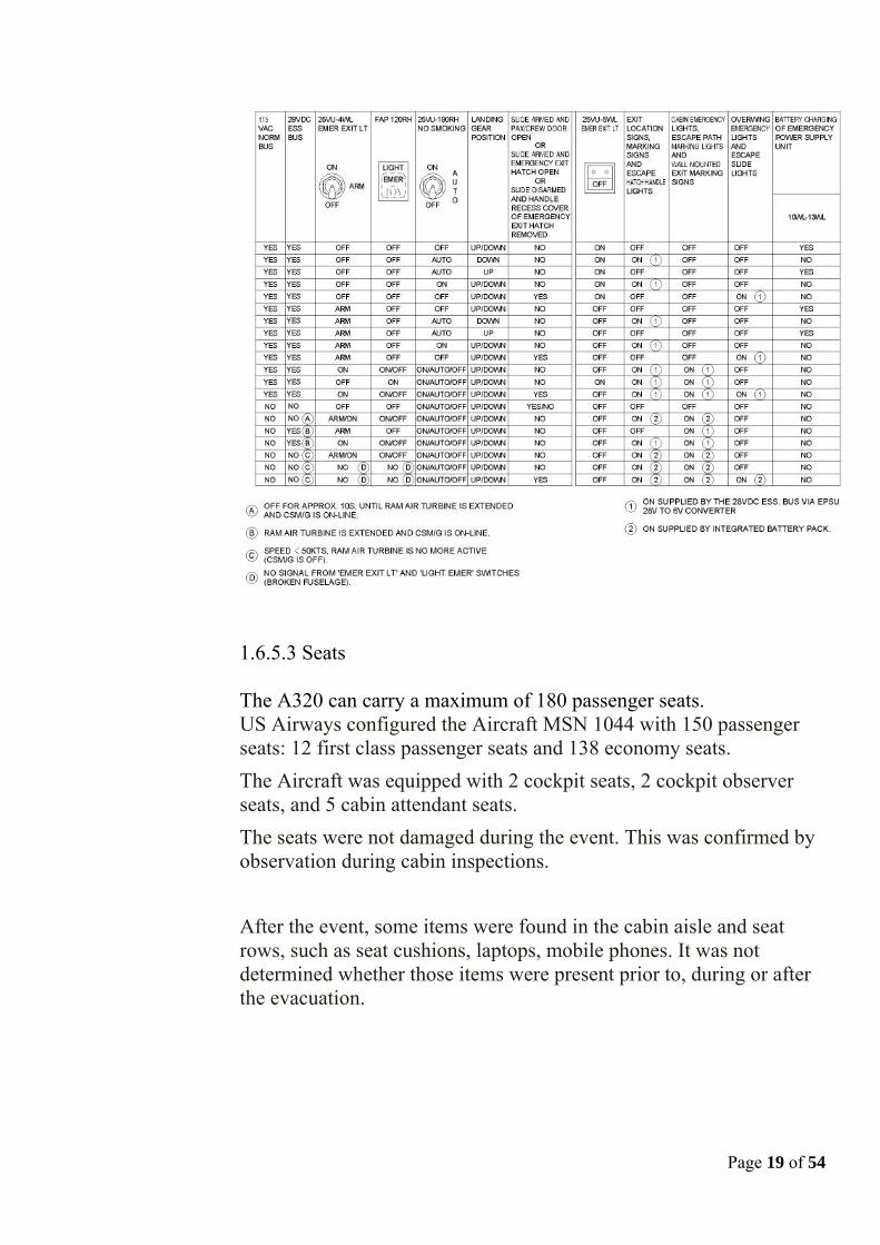
1.6.5.2 Emergency lighting
The 4WL switch on the 25VU was found in the armed position by the investigators after the event. This was confirmed during the Captain interview, where he said that the EMER LTS were armed in the cockpit. Provided that after the emergency water landing, there were neither normal nor essential electrical supply, the cabin emergency lights (escape path marking lights, wall mounted exit marking lights, escape slide lights, ceiling mounted emergency lights, ceiling mounted EXIT locators and overwing emergency lights), are directly supplied from the integrated battery packs, so called EPSUs, for a 15 minute duration.
1.6.5.3 Seats
The A320 can carry a maximum of 180 passenger seats. US Airways configured the Aircraft MSN 1044 with 150 passenger seats: 12 first class passenger seats and 138 economy seats. The Aircraft was equipped with 2 cockpit seats, 2 cockpit observer seats, and 5 cabin attendant seats. The seats were not damaged during the event. This was confirmed by observation during cabin inspections.
After the event, some items were found in the cabin aisle and seat rows, such as seat cushions, laptops, mobile phones. It was not determined whether those items were present prior to, during or after the evacuation.
Page 19 of 54

Page 20 of 54
1.6.5.4 Overhead Stowage Compartments (OHSC) Seven OHSCs were found open, mainly at the rear of the cabin. It was not determined whether the OHSCs openings occurred prior to, during, or after the Aircraft impact on water.
1.6.6. Emergency Equipment This Aircraft was equipped with Extended Overwater (EOW) operations emergency equipment, although Flight 1549 was not an EOW flight. 1.6.6.1 Slide rafts and overwing slides
The Aircraft was equipped with a slide raft at each forward and aft passenger doors. Each slide raft is designed to allow aircraft occupants to evacuate from the aircraft during a ditching, and to have a raft pending rescue. Slide rafts have a portability function allowing to transport them from one door to another door should the initial door be not usable, in accordance with assumptions taken, which are mentioned in the Airbus document entitled “Establishment of Ditching Substantiation” (Ref. 00D025P0002/C12, Issue 1) dated January 21, 1988.
Following the Aircraft water landing, the 2 aft slide rafts were reported to be under water, as a result of the water landing which parameters were far from those considered during the ditching certification of the A320.
From videos taken during the event, the 2 offwing slides did inflate, and at least one was used as a flotation device. By design, the offwing slides are not accounted for as flotation devices since their particular shape is not optimal for a flotation device. Furthermore, they cannot be detached from the aircraft (except during maintenance operation).
The 2 forward doors slide rafts did inflate, and were used during the evacuation. It was reported by the cabin crew that the door 1LH slide raft inflation handle was pulled as per the procedure and that the slide raft deployed.
The door 1RH slide raft automatically deployed and allowed the evacuation of the aircraft occupants. It has been assumed from

interviews and photographic evidences that at some point during the evacuation the door 1RH was no more, or not in its locked open position, and one passenger was assigned to hold it open
The door 1LH slide raft deployed approximately 20 seconds after door opening. From interview, a count of the raft occupants was organized by the captain at least for the door 1LH slide raft. Some interviews reported the FWD slide rafts to be full of occupants. In fact, from NTSB report, 35 passengers boarded the door 1LH slide raft (including post evacuation passenger movements) and 32 occupants were rescued from the door 1RH slide raft. Those slide rafts have a rated capacity of 44 occupants and an overload capacity of 55 occupants when used as a raft.
From flight and cabin crew interviews, the mooring line of both forward slide rafts was cut using a knife borrowed from the rescue ferries. The mooring line is intended to be cut using the dedicated hook knife stored on the raft upper tube in a pocket, RH side of the girt when the raft is inflated. See figures below.
Page 21 of 54

Page 22 of 54

Page 23 of 54
A “knife” inscription is placed on the hook knife pocket flap, and a
“cut mooring line” inscription and an arrow designates the location where the mooring line has to be cut.
During Aircraft recovery from the river, the LH aft door slide raft inflated as soon as the Aircraft LH aft door sill was sufficiently high above the water. 1.6.6.2 Life lines.
Four life lines were installed on the Aircraft. They are intended to assist passengers evacuating an aircraft to remain on the wings after ditching. The cabin crew mentioned that they did not use the life lines during the evacuation. The 4 life lines were retrieved properly stowed in their dedicated OHSCs adjacent the emergency exits (FR 38) left and right.
According to the NTSB survival group factual report, 36 passengers were rescued from the left wing, and 22 passengers were rescued from the right wing. From passenger interviews, a few of them having evacuated the cabin on the wing fell into water.
The life lines placards are on the dedicated OHSCs, showing how the lines are to be installed on the aircraft.
As this flight was a “non EOW” flight, passengers were not briefed on the life line installation and use. 1.6.6.3 Survival kits.
This plane was equipped with survival kits. If needed, they are removed from the stowage and connected to each escape slide raft. They are connected with a snap hook to the survival kit lanyard attach loop. The survival kit lanyard attach loop is attached to the telescopic end fitting of the girt bar.
Survival kits contain survival equipment such as canopy, hand pump, survival manual…They are to be used in case of a ditching, prior to slide raft disconnection from aircraft.

Page 24 of 54
Three survival kits were retrieved properly stowed in the OHSCs, and the fourth survival kit was found lying on the Aircraft cabin floor after the event. 1.6.6.4 Life vests / cushions.
From NTSB survival factor group factual report, 101 passenger life vests were retrieved properly stowed underneath passenger seats in the cabin, mainly at the rear of the plane.
32 seat cushions were retrieved installed on seat throughout the cabin.
This indicates that more seat cushions were used than life vests during the evacuation. It has to be noticed that from cabin crew and passenger interviews, some passengers evacuated the aircraft without taking either a life vest or a seat cushion. 1.6.6.5 Safety card
From the NTSB factual report, the safety information cards were present in all of the emergency exit row seats and a majority of other seatback pockets throughout the Aircraft. Note: The operators produce their own safety information cards in accordance with their applicable regulation. 1.6.6.6 Evacuation
An emergency evacuation signaling system (integrated in the CIDS) was installed on MSN 1044. It provides visual and aural alert in the event of impending emergency evacuation of the aircraft.
Panels provided with control and warning lights are located: - in the cockpit, - at the purser station on the FAP (Forward Attendant Panel), and - at the AFT L attendant station on the AAP (Aft Attendant Panel).
From pictures taken after the event, the cockpit two-position selector switch was on the “CAPT” position, indicating that the evacuation order would have been initiated from the cockpit only.

Page 25 of 54
1.7 Meteorological Information The last METAR available at KLGA was: METAR KLGA 151951Z 34013KT 10SM BKN035 M06/M14 A3022 RMK A02 SLP234 T10611139. 1.8 Aids to Navigation Not applicable 1.9 Communications
There were no reported communication issues between the cockpit crew and the ATC, except that the initial “mayday, mayday, mayday” transmission from the cockpit crew to the ATC was blocked by a simultaneous transmission.
1.9.1. Flight deck – cabin communication.
When flight crew knew they were going to land on the Hudson River, they advised the cabin crew and passengers in the cabin via the Public Address system. The PA announcement of “This is the Captain brace for impact” provided information to the cabin occupants to prepare themselves as far as they could to face an imminent emergency landing. The forward cabin crew realized they were on water when they looked through the passenger door window to assess the evacuation possibilities. The aft cabin crew realized the situation when she looked at door 2LH, seeing water entering the aircraft through this door area.
After the water landing, the captain reported through his interview that he did not perform any PA announcement in order to evacuate since he thought the PA would not work in that configuration. Airbus highlights that the system is designed to function under these circumstances. Note: cabin crews reported having heard the evacuation PA announcement.
1.9.2. Cabin to cabin communication.
From cabin crew interviews, as soon as the information “Brace for impact” was heard from the PA, all cabin crews shouted continuously “Brace, brace heads down stay down”. From the survival group research, this is consistent with US Airways cabin crew operating manual, asking to shout the command “Bend over, heads

Page 26 of 54
down, stay down” as a brace command in case of planned or unplanned situation.
Note: from interviews, some passengers reported that it was difficult to hear the bracing and evacuation instructions
1.10 Airport Information Both LA GUARDIA & TETERBORO airport were considered by the crew. 1.11 Air Traffic Control Information Information are available in NTSB ATC Group Factual Report DCA09MA026. 1.12 Flight Recorders
1.12.1 DFDR
Recorded Altitude
On this DFDR Data Frame, the recorded altitude is always the Standard Altitude equivalent to QNH=1013.25 mB), whatever the Captain or First Officer QNH selection is. Therefore, an additional conversion during the data decoding is necessary in order to re-compute the corrected barometric altitude of the Aircraft at the Bird Strike (Captain and First Officer QNH selection was equal to 1024 mB at that time).
In the cockpit, the PFD’s will display the following altitudes: If in STANDARD selection, Altitude = Standard Altitude from ADIRS (Label 203) = Recorded Altitude on DFDR If in QNH selection: - For Captain PFD: Altitude = Captain Corrected Altitude from ADIRS (Label 204) - For F/O PFD: Altitude = F/O Corrected Altitude from ADIRS (Label 220)
Below is a description of the labels in output of the ADIRS System: The Label 204 is the Captain’s Corrected Altitude with Captain QNH Setting on FCU. The Label 220 is the F/O Corrected Altitude with F/O QNH Setting on FCU.
The Corrected Altitude formula used in ADIRS is the following:

⎥⎥⎦
⎤
⎢⎢⎣
⎡⎟⎠⎞
⎜⎝⎛−×−=
190263.0
25.10131156.145442 QNHeStdAltitudltitudeCorrectedA
Therefore, for a QNH recorded at 1024 mb on both Captain and F/O side, the result will be: Corrected Altitude (displayed altitude for this event) = Standard Altitude (DFDR) + 292ft
Therefore, for a Standard Altitude equal to 2764ft at the Bird Strike, the corrected altitude is 3056ft.
APU
On this DFDR Data Frame, only one parameter is recorded for the APU, but the acquisition logic can give additional information on the status of APU selection at the time of the bird strike and before the forced landing. A Boolean toggling means the status matrix of the label in entry is other than Normal Operation. The APU Bleed Valve is recorded from the ECB through the SDAC (Label 037 Bit 11). The SDAC copies the received label (data and SSM) to send it to the DFDR. In case of no-refresh label at SDAC input level, after a confirmation delay (order of magnitude 2 sec), the SDAC sends to the FDIU/DFDR the label 037 with a "forced" Failure Warning SSM.
Based on the parameter recorded not toggling at 20:27:18 (8s after the Bird Strike), we can conclude that: The APU was not running before that time (for the Takeoff), The APU Master Switch was switched ON at 20:27:18, The APU Bleed Valve was closed.
In addition, the FDIU (acquisition system which acquires and sends the data to the SSFDR) is powered by AC2 BUS. On CFM Engines, the IDG will disconnect from the network as soon as the Engine N2 decreases below 56.3% + 500ms. Engine 2 N2 decreased below 56% at 20:27:17. Engine 1 N2 decreased below 56% at 20:29:29. If APU is started, AC1, AC2 and AC Ess will remain powered. All A/C Bus Bars and Hydraulics were available until the impact with water. Therefore, we can also conclude that the APU was started between the APU Master Switch ON and 20:29:29.
Page 27 of 54

Page 28 of 54
1.12.2 CVR
CVR transcript is available in NTSB group chairman’s factual report of investigation Cockpit Voice Recorder DCA09MA026.
1.13 Wreckage and Impact Information
The damages, including engines attachments breakage which occurred during the Aircraft emergency landing on water are documented in NTSB group chairman’s structure factual report DCA09MA026 Addendum 1
1.13.1 Cargo Doors Both the forward and aft cargo doors were open when the Aircraft was lifted from the river. The aft cargo door was hanging down by gravity, while the forward cargo door was locked in the fully opened position. However from the pictures taken just after the emergency water landing, it is obvious that the forward cargo door was in a closed position at that time. The aft cargo door can’t be seen as it is under water level.
The forward cargo door frames, rollers, latches and drift pins were in good condition and not deformed. The aft cargo door rollers, latches and drift pins were in good condition, and the door frame structure was fractured at multiple locations. Aft cargo door damages are documented in NTSB factual report DCA09MA026 Addendum 2. The Aircraft was initially supported on the barge by the right engine and aft cargo door.
1.13.2 Cabin damage After the Aircraft was dragged and pulled on the barge, the Aircraft cabin was inspected and found being in a relative good general condition.
Cabin floor The cabin floor was damaged at 3 locations:
In the vicinity of row 22 RH side, the floor was damaged, the most significant damage being underneath seat 22E, where the center panel was buckled upward approximately 7-8 inches. In front of the aft swivel cabin attendant seat, a 4 ¾ inch portion of the frame 65 vertical beam was protruding through the cabin floor

In the vicinity of the LH aft galley, the floor was damaged with a deformation upwards of approximately 2-3 inches.
Passengers did not comment upon floor damage. It can be concluded that it did not impede the complete cabin evacuation.
Minimal other damages were noticed regarding different cabin parts.
1.14 Medical and Pathological Information
Not applicable
1.15 Fire There was no evidence of a post crash fire and no evidence or any patterns like those typically associated with a moving or in-flight fire. No soot patterns were identified and no melted or splattered aluminium was observed on any of the structure.
Page 29 of 54

1.16 Survival Aspects The actual water impact conditions (see paragraph 1.17.1) were more severe than the ditching certification assumptions (the impact energy to be “absorbed” by the structure is proportional to the square of the vertical speed), leading to rear fuselage damage. However, despite a rear bottom fuselage opening in the back of the aft cargo compartment, the Aircraft flotation time was sufficient for everyone to safely evacuate the Aircraft. Due to water entering the rear of the cabin, both aft door slide rafts were not used. Although by regulation definition this flight was not considered as an “EOW” flight, the availability of the front doors slide rafts, certainly eased the evacuation process. The overwing exits life lines were not used.
1.17 Tests and Research 1.17.1 Airframe structure
A comparative assessment has been performed by Airbus in between the Ditching Certification values and the actual values for US Airways 1549 emergency landing on water.
mass (lbs)pitch attituaircraft sglide slope rate of des
Ditching Certification US Airways1549 Emergency landing145505 151017
de (°) 11 9.5peed (Kts) 118 125
(°) -1 -3.5cent (ft/s) 3.5 13
The corresponding external pressures for Flight 1549 emergency landing on water were estimated, and the reserve factors for the rear fuselage were calculated for this new loadcase. Each area for which the computed reserve factor is less than one are shown in red on the following drawing
.
Page 30 of 54
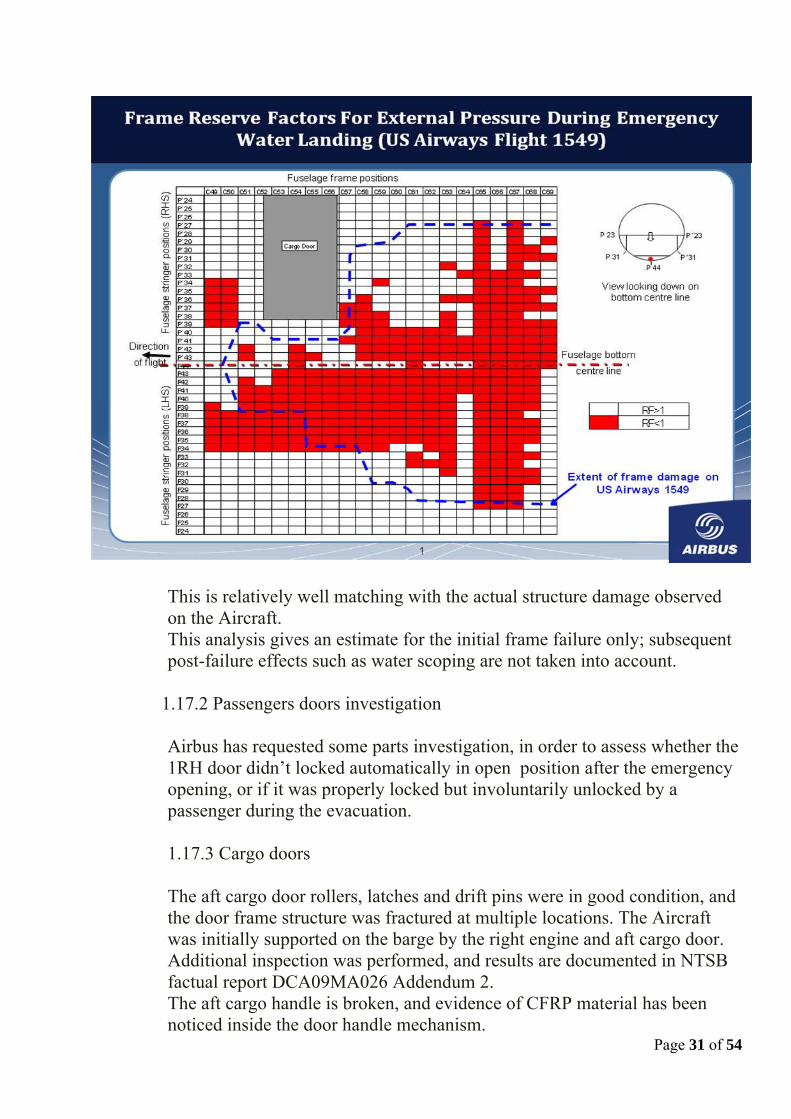
This is relatively well matching with the actual structure damage observed on the Aircraft. This analysis gives an estimate for the initial frame failure only; subsequent post-failure effects such as water scoping are not taken into account.
1.17.2 Passengers doors investigation
Airbus has requested some parts investigation, in order to assess whether the 1RH door didn’t locked automatically in open position after the emergency opening, or if it was properly locked but involuntarily unlocked by a passenger during the evacuation.
1.17.3 Cargo doors
The aft cargo door rollers, latches and drift pins were in good condition, and the door frame structure was fractured at multiple locations. The Aircraft was initially supported on the barge by the right engine and aft cargo door. Additional inspection was performed, and results are documented in NTSB factual report DCA09MA026 Addendum 2.
Page 31 of 54
The aft cargo handle is broken, and evidence of CFRP material has been noticed inside the door handle mechanism.

Page 32 of 54
1.17.4 Flight handling qualities As shown in Memorandum reference D070ME0936142 dated 13 November 2009, simulations performed using a full A320 model demonstrate a good matching between the simulation output (using crew flight controls orders recorded on DFDR as inputs) and the complete DFDR recorded parameters.
1.18 Organizational and Management Information
Not assessed by Airbus
1.19 Additional Information
1.19.1 Certification requirements for transport aircraft 1.19.1.1 Engine birds ingestion
Certification requirements applicable to the accident engines are as follows:
With max 25 % thrust loss: 5 “Small birds” 5 x 1.54 lbs or 1 “Medium bird” 1 x 2.5 lbs With total thrust loss (but contained): 1 “Large bird” 1 x 4lbs Certification requirement for similar engine today:
With max 25 % thrust loss: same requirements for small and medium size birds
With total thrust loss (but contained): 1 “Large bird” 6 lbs
According to NTSB report, Flight 1549 birds remains identified in both engines are from Canada goose which typically ranges in “adult” size:
from 5.8 to 10.7 pounds 1.19.1.2 Event classification versus certification criteria Ditching structural certification requirements can be split in three folds: - Aircraft behaviour: FAR 25.801(c) - Structural integrity and Occupant protection: FAR 25.801 (b) and

Page 33 of 54
(e); FAR 25.561 (a) - Flotation time: FAR 25.801 (d)
Ditching certification does take into account sufficient time for the crew to properly plan, manage and perform all necessary actions for an optimum water landing. This was not the case for USA 1549 accident for the following reasons:
The term “ditching” is currently not defined in FAR 1.1, General Definitions, although the U.S Federal Aviation Regulations (FARs) describe “ditching” as a planned event. The NTSB1 defines “ditching” “as a planned event in which a flight crew knowingly makes a controlled emergency landing in water.” In a 1996 DOT/FAA2 research study on ditching performance of transport category aircraft said that, “Transport aircraft water impacts are classified into two basic categories: ditching (planned) and unplanned water contact. A ditching is an emergency landing in water, i.e., planned water contact. For an official "ditching" to occur, certain impact parameters must be present. The descent rate cannot be greater than 5 ft/sec, and the longitudinal and vertical loads must be within aircraft design parameters… When proper ditching procedures are followed, the occupants should have several minutes to prepare for the impact, which is typically less severe than an unplanned impact because the pilot maintains substantial control of the aircraft.” Similarly in a 1998 DOT/FAA3 study said that a ditching “is usually described as a planned emergency event in which the crew, with the aircraft under control, deliberately lands in water. In contrast would be an inadvertent water impact in which there is little or no time for crew or passenger preparation. Ditching allows some amount of time for donning life preservers and preparing the aircraft and passengers for the emergency.” Finally US Airways4 guidance to its flight crews describes “ditching” as follows: “There are two types of water landings: planned and unplanned. Planned water landings, also known as “ditching,” is characterized by at least some preparation time. The possibility of structural damage is less likely making evacuation easier. In unplanned water landings there will be no time to prepare. The possibility of aircraft damage is more likely followed by flooding and the possible sinking of the aircraft.
1. NTSB Coding Manual 2 DOT/FAA, AR95-54, Transport Water Impact and Ditching Performance, March 1996 3 DOT/FAA/AM98, Analysis of Ditching and Water Survival Training Programs of Major Airframe Manufacturers and Airlines 4 US Airways Student Guide, Section IV – Ditching, January 2008

Page 34 of 54
Based on the above there is industry consensus among the DOT, FAA, NTSB and airlines as to the essential elements that constitute the definition of a “ditching” event and they are: • A certain amount of pre-ditching communication/coordination or
planning for the flight and cabin crew to adequately prepare the flight deck and cabin respectively for the emergency landing.
• The aircraft is flown in a controlled manner and deliberately lands in the water.
By contrast an “unplanned water landing” is when an airplane impacts the water without warning, uncontrolled and or improperly configured, with little or no time for crew or passenger preparation, such accidents are typically inadvertent, with no preparation time, substantial aircraft damage, and a high risk of occupant injury. The FAA5 policy guidance states that “Ditching and water landing are defined differently. Ditching as commonly used in aviation is a planned event. When the airplane lands in the water without warning, this is an “unplanned water landing.”Flight 1549 experienced a dual engine failure at approximately 3000ft and remained airborne three and a half minutes.
There appears to be no significant correlation between the definition of “ditching” and the accident involving Flight 1549. Guidance provided by the DOT, FAA, NTSB and US Airways as to what constitutes a “ditching” is clear. The water landing of Flight 1549 was not a planned event; time is required to allow pre-ditching coordination by either the flight crew or flight attendants that would have allowed them to prepare the Aircraft and passengers for the emergency. For the cabin occupants, a “Brace for impact” call was given shortly before water impact. The only factor in the event that is somewhat consistent with the definition of “ditching” is that the crew intentionally landed the Aircraft in the water.
Similarly “Unplanned water landings” generally involves an uncontrolled high energy impact near an airport that results in severe injuries due to higher aircraft velocities, forces, and subsequent damage encountered at impact.
It is readily apparent therefore that the Flight 1549 accident in the Hudson River cannot be classified as a “ditching” (planned water
5 FAA FSIMS 8900.1 CHG 0, VOL 3, CH 30, 2007, Emergency Evacuation and Ditching Demonstration

Page 35 of 54
landing) as it does not meet the “ditching” criteria. The specifics of the event do not comply with any of previously established definitions.
Research and accident investigative studies accomplished in the past 40 years by the DOT, FAA and NTSB on ditching, water impact and water survival equipment and procedures have consistently classified water landings as either planned or unplanned, with a planned water landing being commonly referred to as “ditching. But the events surrounding Flight 1549 clearly indicate that the crew deliberately landed the Aircraft in water, in a slats/flaps configuration 2 (instead of the QRH prescribed configuration 3) with little or no warning, with little or no time for crew or passenger preparation. On February 24, 2009, Peggy Gilligan, Associate Administrator for Aviation Safety testified before the U.S. House of Representatives, Committee on Transportation and Infrastructure, Subcommittee on Aviation Concerning US Airways Flight 1549, stated that “This was a truly extraordinary event in aviation history: a multiple bird ingestion that virtually simultaneously caused engine failure in both engines of a commercial airliner on takeoff…with no loss of life.”
Page 36 of 54
2 ANALYSIS
2.1 Reconstruction of aircraft performance from DFDR data 2.1.1 Overall flight
The FDIU (acquisition system which acquires and sends the data to the SSFDR) is powered by AC2 BUS. On CFM Engines, the IDG will disconnect from the network as soon as the Engine N2 decreases below 56.3% + 500ms. Engine 2 N2 decreased below 56% at 20:27:17. Engine 1 N2 decreased below 56% at 20:29:29. If APU is started, AC1, AC2 and AC Ess will remain powered. All A/C Bus Bars and Hydraulics were available until the ditching. Therefore, we can also conclude that the APU was started between the APU Master Switch ON and 20:29:29. The initial action by the Captain to select the APU allowed using the APU electrical generation at the time of the engine N°1 re-start attempt, thus remaining in Normal Law and keeping all displayed information available to the crew even during that time. 2.1.2 Engines behaviour ATHR remained active until both levers are pulled back on the Idle detents. Under these conditions, N1 commanded is equal to the N1 Target from the FMGC and in open climb AP mode also equals N1 TLA. However should there be a delta between N1 actual and N1 command the blue arc is displayed between the two points. This provides an indication that the engine is not delivering the commanded thrust but that the engine is still delivering power. In response to a bird strike or an engine compressor stall the flight crew would typically pull the throttle back and then move it back forward. The N1 response should then correlate to the throttle position hence providing further feedback to the flight crew on the engine health and responsiveness to a power demand.

DFDR Data:
Bird Strike
At 20:27:10, the DFDR indicates a sudden drop down recorded on N1 and N2 values for both engines: Engine 1: N1 from 82% down to 35%, N2 from 94% down to 85%, Engine 2: N1 from 82% down to 14%, N2 from 94% down to 35%.
Immediately following the bird strike, EGT increase on both engines: Engine 1: up to 890 Deg C before both TLA Reduced to IDLE clutch at 20:27:57,
Page 37 of 54

Engine 2: up to 891 Deg C before Engine 2 High Pressure Fuel Valve closure at 20:28:29.. At this point, Airbus considers the engine indications are consistent with the physical consequences of the bird impact.
The Thrust Levers were retarded to IDLE at 20:27:57. ATHR deactivated and disengaged at the same time. Then Thrust Lever Engine 1 is slightly increased up to CLIMB notch at 20:28:54. N1 / N2 on Engine 1 increasing again up to 34% / 82%.
Engine 2 Relight Attempt
Page 38 of 54

Engine 1 Relight Attempt
At 20:29:26, Fuel Fire Valve on Engine 1 recorded closed, and then Not Fully closed 9s later. At the Fuel Fire Valve closure, a peak recorded on EGT1 parameter.
At the Fuel Fire Valve closure, HP Fuel Valve was recorded closed and Fuel Flow dropped down to 0 Kg/h accordingly. At the Fuel Fire Valve aperture, HP Fuel Valve was recorded not closed and Fuel Flow increased up to 336 Kg/h (to be compared with 1000 Kg/h before the Engine 1 Relight). N1 was recorded decreasing down to 14% then increasing up to 16%, and then slightly decreasing until the ditching.N2 was recorded decreasing down to 37% and then slightly increasing up to 51% before the ditching. EGT1 suddenly decreased from 899 Deg C down to 663 Deg C, and then slightly increased up to 779 Deg C before decreasing until to the ditching.
Page 39 of 54

Page 40 of 54
Master Warning recorded at the Fuel Fire Valve closure
In conjunction with the CVR transcript the DFDR data is consistent with the relight attempts during the descent.
Extract NTSB Power Plant Group factual report Comments on CVR transcript
About 30 seconds later, at 15:28:30, the FDR records that the No. 2 engine HP fuel valve goes from the NOT CLOSED position to the CLOSED position consistent with the engine master switch being placed in the OFF position. The No. 2 engine N2 speed was essentially at 35% when the HP fuel valve was CLOSED. According to the US Airways A310/A320/A321 Flight Crew Operating Manual (FCOM) for an automatic start sequence, with the engine mode selector is in the IGN position and the throttle back at idle, the HP will OPEN only when the N2 speed is greater than 15% when in flight. 5) The wind milling relight speed for a CFM powered A320 is 300 knots. Pilot statements. the engine master switch was cycled back to the ON position in an attempt to start the engine; however, the HP fuel valve remained in the CLOSED position for the remainder of the flight. This is consistent with engine master switch being placed in the ON position some time after 15:28:54 since all values for N2
Airbus comment The HP valve closes, shown on our plots at about 20:28:30 and consistent with Fuel Flow dropping to zero, but the LP fuel valve does NOT close nor do we notice a FADEC parameter bounce. Closure of the LP valve and FADEC parameter bounce, at the same time that the HP valve closes, would be consistent with M/L placed to OFF. The closure of the HP valve remains an inconsistency. With regards to the CVR, the closure of the HP valve at 15:28:30 is also inconsistent with the CVR recording of M/L commanded OFF at 15:29:07, i.e. approx thirty seven seconds later Airbus comment: The fuel valve will open if there is enough fuel pressure.
The pilots follow the QRH checklist, see CVR script: 15:27:50 ..if fuel remaining, eng mode selector ignition 15:27:54 ignition 15:27:55 thrust levers confirm idle 15:27:28 idle 15:28:02 airspeed (for) optimum relight three hundred knots 15:28:05 we don’t ( have ) 15: 28:05 if three nineteen .. 15: 28:14 emergency electrical power ..emergency generator not on line 15:28:18 noise from cockpit area microphone “ sound similar to electrical noise from engine igniters (note: this is probably an electrical transfer, indicating that the emergency gen has been manually selected on) 15:28:19 it’s online This could indicate the crew selected it like that. 15:28:21 ATC notify squawk seventy seven hundred 15:28:25 yeah, the left one is coming back up a little bit 15:28:30 distress message transmit.. we did 15:28:37 (he wants us) to come in and land on one
Page 41 of 54
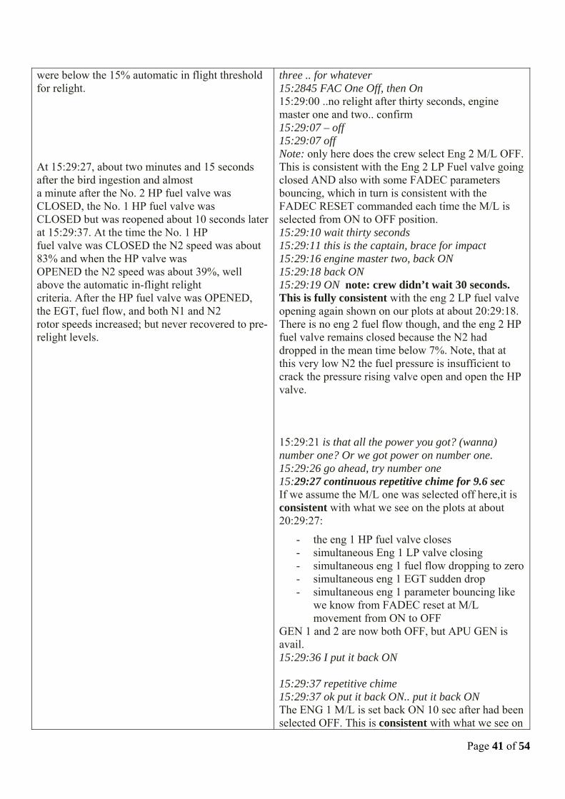
were below the 15% automatic in flight threshold for relight. At 15:29:27, about two minutes and 15 seconds after the bird ingestion and almost a minute after the No. 2 HP fuel valve was CLOSED, the No. 1 HP fuel valve was CLOSED but was reopened about 10 seconds later at 15:29:37. At the time the No. 1 HP fuel valve was CLOSED the N2 speed was about 83% and when the HP valve was OPENED the N2 speed was about 39%, well above the automatic in-flight relight criteria. After the HP fuel valve was OPENED, the EGT, fuel flow, and both N1 and N2 rotor speeds increased; but never recovered to pre-relight levels.
three .. for whatever 15:2845 FAC One Off, then On 15:29:00 ..no relight after thirty seconds, engine master one and two.. confirm 15:29:07 – off 15:29:07 off Note: only here does the crew select Eng 2 M/L OFF. This is consistent with the Eng 2 LP Fuel valve going closed AND also with some FADEC parameters bouncing, which in turn is consistent with the FADEC RESET commanded each time the M/L is selected from ON to OFF position. 15:29:10 wait thirty seconds 15:29:11 this is the captain, brace for impact 15:29:16 engine master two, back ON 15:29:18 back ON 15:29:19 ON note: crew didn’t wait 30 seconds. This is fully consistent with the eng 2 LP fuel valve opening again shown on our plots at about 20:29:18. There is no eng 2 fuel flow though, and the eng 2 HP fuel valve remains closed because the N2 had dropped in the mean time below 7%. Note, that at this very low N2 the fuel pressure is insufficient to crack the pressure rising valve open and open the HP valve. 15:29:21 is that all the power you got? (wanna) number one? Or we got power on number one. 15:29:26 go ahead, try number one 15:29:27 continuous repetitive chime for 9.6 sec If we assume the M/L one was selected off here,it is consistent with what we see on the plots at about 20:29:27:
- the eng 1 HP fuel valve closes - simultaneous Eng 1 LP valve closing - simultaneous eng 1 fuel flow dropping to zero - simultaneous eng 1 EGT sudden drop - simultaneous eng 1 parameter bouncing like
we know from FADEC reset at M/L movement from ON to OFF
GEN 1 and 2 are now both OFF, but APU GEN is avail. 15:29:36 I put it back ON 15:29:37 repetitive chime 15:29:37 ok put it back ON.. put it back ON The ENG 1 M/L is set back ON 10 sec after had been selected OFF. This is consistent with what we see on

Page 42 of 54
the plots from about 20:28:38:
- ENG 1 HP fuel valve opening (note, that fuel press was sufficient since N2 at about 38%)
- Eng 1 LP valve opening - Fuel flow establishing at start FF of about 380
kg/hr - EGT rising from about 660 deg C where it
had dropped after S/D - N2 rising from about 38% deg C where it had
dropped after S/D, to about 51%, insufficient to reconnect the GEN 1 (57%N2+2.6sec)
15:29:37 too low terrain 15:29:41 too low terrain 15:29:43 too low terrain 15:29:44 no relight ( probably addressing eng 2 or the fact that eng 1 did not recover to thrust )
PFR Data:
GMT approx
Event Engine reaction ECAM/Post Flight Report
20.24.56 Initial Throttle Push for Take-Off
20.25.08 Throttle Push for Take-Off (TOGA/45 DEG TLA)
Both engines accelerate normally and reach 88% N1
“Engine” Page up on ECAM SD, as expected.
20.25.52 Slight N2 increase on both engines (1.5%) at constant N1
20.26.00 Throttle reduction to CLB gate (25 DEG TLA)
Both engines reduces to CLB N1 (80%) ATHR active (Open Climb) N1 VIB increases from 1.4 to 2.7 CU
“Cruise” Page up on ECAM, as expected
20.26.06 “Engine” Page Up on ECAM 20.26.48 Slight N1 increase on both
engines (80 to 82%)
20.26.52 “Cruise” Page up on ECAM 20.27.12 Dual & simultaneous
engine thrust loss N1_1 from 82%CLB to 35%, with N1 CMD at 80% N2_1 from 94 to 86%, then 83% EGT 1 steep increased from 640°C to 880°C No noticeable effects on N1 & N2 VIB
No warning on ENG 1, as ECAM engine parameters remain within limits ENG2 START FAULT ENG2 STALL (Sub-idle stall

Page 43 of 54
N1_2 from 82%CLB to 14%, N2_2 from 94 to 35%, EGT 2 steep increased from 680°C to 890°C N1_2 VIB up to 3.5 CU N2_2 VIB up to 6.2 CU
detection, based on N2 decay) “Engine” Page up on ECAM, as expected
20.27.17 N2_2 reduces below 57% GEN FAUL Warning confirmation time > 4.5 sec.
20.27.22 APU Bleed valve signal from NCD to CLS
N2_2 reduces below 50%. N1C_2 is set to “N1C_2=N1_2A (14 to 16%N1) Oil Low Press. on ENG 2 sets when N2 reaches 44% N2.
ENG2 FAILED (N2 below 50%) By design, GEN 2 FAULT & “ENG 2 OIL LO PR” warnings inhibited by Engine Not Running condition (below 50% N2).
N1_1 remains at about 35%, N2_1 at 83% above idle, with EGT rising from 640 to 880 deg C with constant fuel flow of about 1000 kg/hr. ENG 2 remains low sub idle at about 14 to 16% N1_2, 35% N2_2 with EGT rising from 670 to 890 with constant fuel flow of 200 kg/hr.
20.27.56 ECU channel switchover on ENG 2 (Ch.B to Ch.A).
20.27.57 TLA 1 and 2 to Idle ENG 1 decels from 35% N1/82% N2 to 22% N1/64%N2 ATHR disengaged. ENG 2 does not react. EGT2 continuous to rise.
AUTO FLT ATHR OFF on ECAM
20.28.14 TLA 1 towards CLB gate TLA 2 remains at idle
ENG 1 re-accels up to 34% N1/83%N2 with EGT rising from 660 and beginning to stabilize towards 900 deg C EGT 2 continuous to rise
20.28.28 ENG 2 HPSOV OFF ENG 2 fuel flow stops, ENG 2 N2 & EGT decay. No trace of LP Valve ENG 2 Closure (“FFV” DFDR parameter)
Page 44 of 54
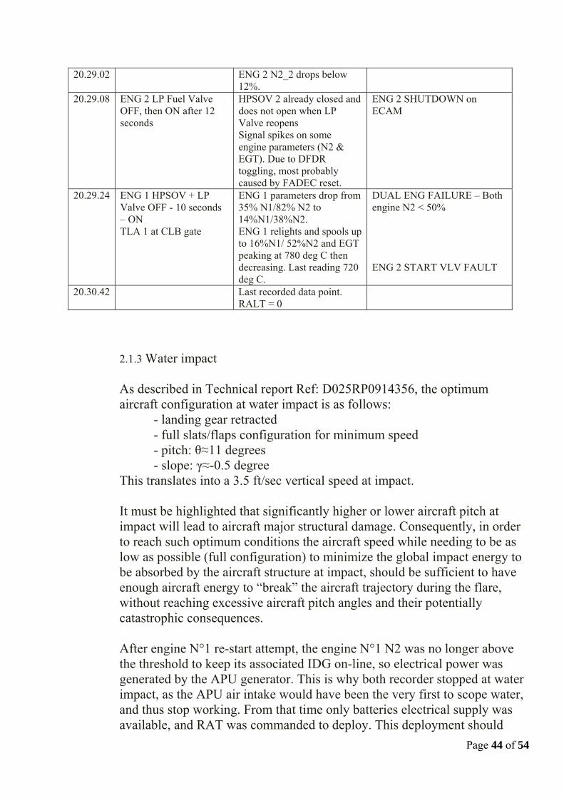
20.29.02 ENG 2 N2_2 drops below 12%.
20.29.08 ENG 2 LP Fuel Valve OFF, then ON after 12 seconds
HPSOV 2 already closed and does not open when LP Valve reopens Signal spikes on some engine parameters (N2 & EGT). Due to DFDR toggling, most probably caused by FADEC reset.
ENG 2 SHUTDOWN on ECAM
20.29.24 ENG 1 HPSOV + LP Valve OFF - 10 seconds – ON TLA 1 at CLB gate
ENG 1 parameters drop from 35% N1/82% N2 to 14%N1/38%N2. ENG 1 relights and spools up to 16%N1/ 52%N2 and EGT peaking at 780 deg C then decreasing. Last reading 720 deg C.
DUAL ENG FAILURE – Both engine N2 < 50% ENG 2 START VLV FAULT
20.30.42 Last recorded data point. RALT = 0
2.1.3 Water impact As described in Technical report Ref: D025RP0914356, the optimum aircraft configuration at water impact is as follows: - landing gear retracted - full slats/flaps configuration for minimum speed - pitch: θ≈11 degrees - slope: γ≈-0.5 degree This translates into a 3.5 ft/sec vertical speed at impact. It must be highlighted that significantly higher or lower aircraft pitch at impact will lead to aircraft major structural damage. Consequently, in order to reach such optimum conditions the aircraft speed while needing to be as low as possible (full configuration) to minimize the global impact energy to be absorbed by the aircraft structure at impact, should be sufficient to have enough aircraft energy to “break” the aircraft trajectory during the flare, without reaching excessive aircraft pitch angles and their potentially catastrophic consequences. After engine N°1 re-start attempt, the engine N°1 N2 was no longer above the threshold to keep its associated IDG on-line, so electrical power was generated by the APU generator. This is why both recorder stopped at water impact, as the APU air intake would have been the very first to scope water, and thus stop working. From that time only batteries electrical supply was available, and RAT was commanded to deploy. This deployment should

have occurred during the “landing roll” and explain why the RAT was retrieved intact in its deployed position when the Aircraft was pulled out of the river.
2.2 Operational aspects
ATHR remains active until both levers are pulled back to the Idle detents. Under these conditions, N1 commanded will equal the N1 Target from the FMGC and in open climb AP mode also equals N1 TLA.
However should there be a delta between N1 actual and N1 command the blue arc is displayed between the two points. This provides an indication that the engine is not producing the commanded thrust but the engine is still producing power. In response to a bird strike or an engine compressor stall the flight crew would typically pull the throttle back and re-accelerate. The N1 response should correlate to the throttle position hence providing further feedback to the flight crew on the engine health and responsiveness to a power demand. CVR records do evidence that, on top of the physical perception of the Aircraft deceleration, the crew properly identified from the displays that both engines were rolling back.
During the flight time in between the birds and the water impacts, the Aircraft was flown occasionally within the alpha protection range (around 1 minute 7s), notably from about 150 ft RA down to water impact. As far as aircraft trajectory is concerned, it has to be noted that the flight control laws in the alpha protection domain do include some additional features. AoA protection takes also care of the aircraft trajectory and, thus, looks after phugoid damping as well as AoA control. There are feedbacks within the AoA protection law aiming at damping the phugoid mode (low
Page 45 of 54

Page 46 of 54
frequency mode). Without these feedbacks, an aircraft upset from its stabilized flight point up to constant high AoA would enter a phugoid (which is, by definition, a constant AoA oscillation) without possibility to stabilize the trajectory. As a consequence, commanded AoA is modulated: for instance, if aircraft speed is decreasing and/or pitch attitude is increasing, pilot's commanded AoA is lowered in order to avoid such a situation to degrade. Trying to run simulation without such damping features on the very last seconds of the flight, without considering what could have been the effect such features brought upstream during the flight on the overall Aircraft trajectory and management by the crew would be pure speculation, as not supported by technical facts.
On the last 10 sec in the air of Flight 1549 , DFDR data show that pitch attitude is increasing and CAS decreasing. Then, the phugoid damping terms are non null and are acting in the sense to decrease the finally commanded AoA vs. the stick command, in order to prevent the Aircraft from increasing the phugoid features.
It is obvious that achieving the optimum water impact configuration when engine thrust is available (actually setting a Flight Path Angle of -0.5° on the FCU), is more easily achievable. However with a loss of engine thrust, as in Flight 1549, the aircraft energy management significantly increases the pilot workload. Under these circumstances, aircraft is still able to reach the optimum water impact configuration, but this is a demanding task which requires time and significant pilot focus. Typically, the flare initiation height will be critical to the achievement of the optimum water entry conditions. Airbus is currently working to further improve support to crews facing an emergency situation at low altitude.
2.3 Survival aspects
2.3.1 Cabin integrity Although the fuselage sustained significant damage in the rear lower area, leading to the aft doors being unusable, the cabin maintained its structural integrity, thus protecting the passengers and crew from major injury and allowing a safe evacuation of the Aircraft. This

Page 47 of 54
demonstrates that the Aircraft met both the intend and the spirit of the certification requirements.
2.3.2 Evacuation means The announcement made on the PA by the flight crew was “This is the Captain brace for impact”. This information advised cabin crew and passenger to prepare themselves as far as they could to face an upcoming emergency landing. The forward cabin crew realized they were on water when they looked through the passenger door window to assess the evacuation possibilities. The aft cabin crew realized the situation when she looked at door 2LH, seeing water entering the aircraft through the door area.
Note: US Airways cabin crew operations manual mentions that in case of planned emergencies, the cabin crew A has to immediately pick up the interphone in order to receive information from the cockpit (called T.E.S.T briefing: Time available, type of Emergency, brace Signal, Take special instructions).This action sequence was not reported either by the flight crew or by the cabin crew. It is clear that this event was an immediate emergency landing on water, during which cockpit crew had insufficient time to plan every single action, and the cabin crew had no opportunity to prepare for the exact nature of the actual emergency.
The captain stated in his interview that he did not perform any PA announcement to evacuate the aircraft as he thought that the PA would not work in that configuration. Airbus has confirmed that the PA is designed to function under these circumstances.
From the various passenger interviews, a large number of the passengers did not recall seeing any emergency lights illuminated in the cabin at the time of the event. This event happened during a very clear day, at 03:30 pm local, when it is very difficult to distinguish emergency lights in that situation, due to the fact that their main purpose is to provide sufficient illumination to allow to see the emergency signs in the cabin shall it be in a dark environment (during night for instance). A check of the emergency light function is to be performed on a regular basis. Based on the fact that no anomalies concerning cabin emergency lights were reported by US Airways, it seems highly probable that all lights worked properly, but remained unnoticed by

Page 48 of 54
the passengers as the emergency indications were sufficiently visible in a daylight environment.
From passenger interviews, a few of them have stated that after successfully evacuating the cabin on to the wing, they slipped and fell into water. Overwing exits life lines may have prevented some of these falls.
2.3.3 Passenger doors It has been assumed from interviews and photographic evidences that at some point during the evacuation the door 1RH was no more, or not in its locked open position, and one passenger was assigned to hold it open This situation does show the appropriate actions taken by the cabin crew, i.e. assigning an able passenger to a door in order to help evacuating the plane. Airbus has requested some parts investigation, in order to assess whether the 1RH door didn’t locked automatically in open position after the emergency opening, or if it was properly locked but involuntarily unlocked by a passenger during the evacuation. The inflation of the door 2LH slide raft during Aircraft recovery from water indicates that this door had been previously opened from inside the cabin while the door was “ARMED”. At that time the slide raft did not inflate as there was not a sufficient height for the slide raft pack drop to trigger the inflation, and the inflation command (red handle) was not activated. This area was probably already under water level. In case the aft doors sill are below water level, it is possible to transport aft doors slide rafts to forward doors and operate them from the forward doors in order to get the global passengers and crew capacity. As per mandatory requirements, cabin crew are shown yearly how to perform such task. In this particular event, even if technically achievable, the slide rafts removal from the aft doors would have been extremely difficult because their area was partially submerged by water. Furthermore the proximity and the quick availability of the rescue means did not make such operation necessary because of the Aircraft flotation behaviour. It is not possible to speculate whether or not cabin crews would have been able to perform this slide rafts removal even in extremely difficult environment in a life threatening situation without “immediate” rescue means available.

Page 49 of 54
2.3.4 Cargo doors Despite the forward cargo door was in a fully open and locked position when the Aircraft was pulled out of the river, the photos available clearly show that the forward cargo was in a closed position after the Aircraft impacted the water and came to a stop. For comparison purposes, photos from a production aircraft have been taken from a similar angle than the ones from the accident Aircraft (see following pictures). Furthermore, the gradual and slow sinking of the Aircraft from the back, does not suggest any opening of the forward cargo door during that period of time. As far as the aft cargo door is concerned, it seems from available evidences that the aft cargo door handle opened by itself due to the aircraft high vertical speed at water impact. Study is on-going to determine whether such scenario could have happened at the optimum vertical aircraft speed at water impact. However it must be emphasized that due to the aft lower fuselage breach created by the high aircraft vertical speed at water impact, the possible opening of the aft cargo door did not change the aircraft flotation characteristics in the USA 1549 accident.

Water level from above picture
Page 50 of 54

Page 51 of 54

Page 52 of 54
3 Conclusions
3.1 Findings 1. The Aircraft and its engines suffered multiple birds strike at around
3000ft. 2. The identified birds remains found in both engines correspond to Canada
geese which average weight is significantly greater than the weight of the birds the engines were, and even are today certified to withstand.
3. Despite suffering bird(s) ingestion in both engines, the engines did not suffer any uncontained failure but continued to deliver hydraulic and electrical power (engine N°1 N2 was high enough, up to the re-start attempt, for its IDG to remain on-line).
4. Captain immediately took over as Pilot Flying, started the APU (while engine N°1 IDG was still delivering electrical power ), and directed the co-pilot to accomplish the QRH “ ENG DUAL FAILURE” procedure.
5. The damage sustained by the engines during this event precluded any possibility of restoring sufficient thrust to maintain level flight.
6. The primary engine displays, N1 and EGT provided the appropriate indications to the flight crew after the bird impact (reduction in N1, increase in EGT) and during the subsequent relight attempts. This is consistent with FAR25.1305 and the current FAA guidance material on engine malfunction flight crew interpretation.
7. From the time Flight 1549 suffered birds ingestion into both engines until it finally impacted the water, the Aircraft flight controls always remained in Normal law with hydraulic power available.
8. The early APU start initiated by the Captain, allowed the Aircraft to remain in Normal law during and after the engine N°1 re-start attempt.
9. Although an emergency return to La Guardia Runway 13 was technically feasible from an aircraft flight performance point of view, the emergency landing on the Hudson seems the most appropriate decision.
10. Flight crew properly focused on their priorities of flying the Aircraft and going through the check-list. They notify the cabin occupants to brace for impact.
11. During the portion of flight after the birds’ impacts, the Aircraft was occasionally flown within the Alpha protection range. Thanks to the flight envelope protection the crew could fly the Aircraft vertical trajectory without getting in and out stick shaker.
12. Captain announced “brace for impact” approximately 89 seconds before impact at approximately 1000 ft RA.
13. Cockpit crew did not have enough time to complete the QRH “ENG DUAL FAILURE” check list.
Page 53 of 54
14. Based on the limited time available to the crew and to the highly constrained environment, this accident is an emergency landing on water.
15. Airbus is currently reviewing how to further support crews facing an emergency at relatively low altitude where they might have insufficient time to refer to a QRH paper procedure.
16. The A320 aircraft certified ditching condition based on NACA and Airbus studies take into account an aircraft water impact with landing gear retracted, slats/flaps configuration full for minimum speed, an optimum pitch angle of 11° and a slope of -0.5°, which translate into a vertical speed of 3.5ft/s
17. The Aircraft impacted the water with landing gear retracted, slats/flaps configuration 2 at 125 kts, a pitch angle of 9.5° and a slope of -3.5°, which translate into a vertical speed of 13ft/s.
18. The actual amount of energy to be absorbed by the structure at water impact was significantly higher than the certified level, thus leading to rear lower fuselage significant deformation and breakage.
19. Although the fuselage sustained significant damage, leading to water entry and consequently aft doors becoming unusable, the cabin maintained its structural integrity, thus protecting the passengers and crew from major injury, allowing a safe evacuation of the Aircraft.
20. Cabin crew discovered the Aircraft was on water only after accessing their respective door.
21. Flight 1549 was not an “EOW” flight, and as such did not require specific emergency equipment such as rafts, nor dedicated water landing briefing prior to take-off.
22. Although Flight 1549 was a non “EOW” flight, the availability of the front doors slide rafts eased the evacuation and rescue processes.
23. Five persons have been reported with “serious injury”. 24. Finally after Flight 1549 emergency landing on water, there were no
fatalities among the Aircraft’s 155 occupants and to Airbus’s knowledge no one suffered any permanent incapacitation.
3.2 Probable Cause
The probable cause of the accident involving Flight 1549 was the significant loss of engines thrust, not allowing to keep a level flight, induced by the ingestion of several Canada Geese into both engines at approximately 3000ft. Those Canada Geese have an average weight which is well beyond the weight considered for engine bird ingestion certification.

Page 54 of 54
4 Recommendations
4.1 Previously issued recommendations
4.1.1Pre-flight briefing Airbus concurs with NTSB recommendation A-85-39 to include a full demonstration of correct life preserver donning procedures during all pre-departure briefings.
4.1.2 ATC identification of aircraft in emergency
Airbus concurs with NTSB recommendation A-09-112 to improve ATC identification of aircraft experiencing an emergency.
4.2 New recommendations
4.2.1 Crew training
Airbus recommends that Authorities ensure that flight and cabin crew training do include an opportunity to realize the nominal and the overloaded amount of people which can be boarded on a given slide raft and/or life raft. This will contribute to an optimum utilization of available emergency equipment.
4.2.2 Emergency equipment briefing
Airbus recommends that Authorities review the need for extended specific briefing and/or safety cards with extended information for people located at aircraft overwing exits for them to be aware of available safety equipment such as life lines and their associated appropriate use.
4.2.3 Safety cards Airbus recommends that Authorities review, and ensure consistent content of all operators’ cabin safety cards.