URSA manual
104
Installation and Operation Manual Blackmagic URSA & URSA Mini April 2016
-
Upload
duongkhanh -
Category
Documents
-
view
256 -
download
0
Transcript of URSA manual
Installation and Operation Manual
Blackmagic URSA& URSA MiniApril 2016
Welcome
Thank you for purchasing Blackmagic URSA!
Since we released our first digital film camera a few years ago we have been privileged
to have received some of the best guidance and feedback we have ever had for a new
product! We all grew up admiring the work of the world’s leading cinematographers
and DOPs and it’s been an honor to spend hours in conversations with these legendary
experts on the features we need to add to our cameras. Of course, everyone we speak
to has good ideas also!
All those exciting conversations have been put into the new camera you have just
purchased. We think it takes care of the needs of large film crews as well as having all
the features you need if you’re operating in single person shooting. Blackmagic URSA’s
unique design allows you to replace the sensor, adding new imaging capability to it over
time. What this also means is we could put more value into the screens, processing and
cooling systems your camera has, because it does not need to be thrown away every
time we develop a new sensor for it!
With URSA, you get a large 10 inch on set monitor built in, dual CFast recorders that
alternate recording so you can keep recording for as long as you want, as well as
scopes, super strong metal design and much more.
Our new URSA Mini camera offers similar capabilities. You get a super strong metal
chassis, dual CFast recorders, a 5 inch touchscreen and the same amazing sensor all in a
smaller, lighter package perfect for single operators. We also listened to single operators
when we developed our new URSA Viewfinder which is perfect when you need extra
precision and for shooting on the shoulder.
We hope you use your URSA or URSA Mini to produce some of the world’s most exciting
films and television programming, music videos and commercials! We are extremely
excited to see what creative work you produce and to get your feedback on new
features you would like to see us add to URSA!
Grant Petty
CEO Blackmagic Design
English
Contents
Blackmagic URSA and URSA Mini
Getting Started 5
Attaching the Handle 5
Attaching a Lens 6
Turning Your Camera On 7
CFast Cards 8
Inserting a CFast Card 8
Choosing a CFast 2.0 Card 9
Preparing a CFast Card for Recording 9
Preparing CFast Cards on a Mac OS X Computer 11
Preparing CFast Cards on a Windows Computer 11
Recording 12
Recording Clips 12
Recording Duration Table 15
Playback 17
Playing Back Clips 17
Blackmagic URSA Overview and Connectors 18
DOP Station 18
DOP Station Buttons and Touchscreen 20
Memory Card Slots 21
Camera Assist and Audio Station 21
Camera Assist and Audio Station Connectors 22
Front Panel and Turret 24
Rear Panel 25
Top Panel and Underside 26
Touchscreens 26
Touchscreen Features 27
Blackmagic URSA Mini Overview and Connectors 29
Front Panel 29
Left Side 30
Right Side 30
Rear Panel 31
Top Panel 32
Underside 33
Camera Buttons and Touchscreen 33
Control Buttons 34
Side Handle 36
Touchscreen 36
Settings 38
Dashboard 38
Camera Settings 38
Audio Settings 42
Recording Settings 43
File Naming Convention 47
Display Settings 47
Entering Metadata 52
The Slate 52
Camera Video Output 53
HD Monitoring Output 53
12G-SDI Output 53
Blackmagic URSA Viewfinder 54
Mounting Batteries 59
Mounting V-mount or Gold Mount Batteries 59
Using your own Battery Plate 60
Using DaVinci Resolve 62
Importing your Clips 62
Editing your Clips 63
Trimming Clips 64
Mapping Keyboard Shortcuts 65
Adding Transitions 66
Adding Titles 67
Adding Audio Tracks 67
Color Correcting your Clips 68
Contents
Contents
Blackmagic URSA and URSA Mini
Using Scopes 69
Secondary Color Correction 70
Qualifying a Color 71
Adding a Power Window 71
Tracking a Window 72
Using Plugins 73
Mastering your Edit 73
Controlling URSA Mini with ATEM Camera Control 75
Using Camera Control 76
Zoom Control 78
DaVinci Resolve Primary Color Corrector 81
Synchronizing Settings 84
Blackmagic Camera Setup Utility 84
Post Production Workflow 85
Working with Files from CFast 2.0 Cards 85
Working with 3rd Party Software 86
Using Final Cut Pro X 86
Using Avid Media Composer 87
Using Adobe Premiere Pro CC 88
Using Autodesk Smoke 2013 88
URSA Mini Shoulder Mount Kit 90
Shimming the PL Mount 94
URSA Mini B4 Mount 96
URSA Mini B4 Lens 98
Upgrading the Sensor Turret on the URSA Model 99
Help 103
Warranty 104
Contents
Getting StartedGetting started with your Blackmagic URSA or URSA Mini is as simple as attaching the handle, mounting a lens, and powering your camera.
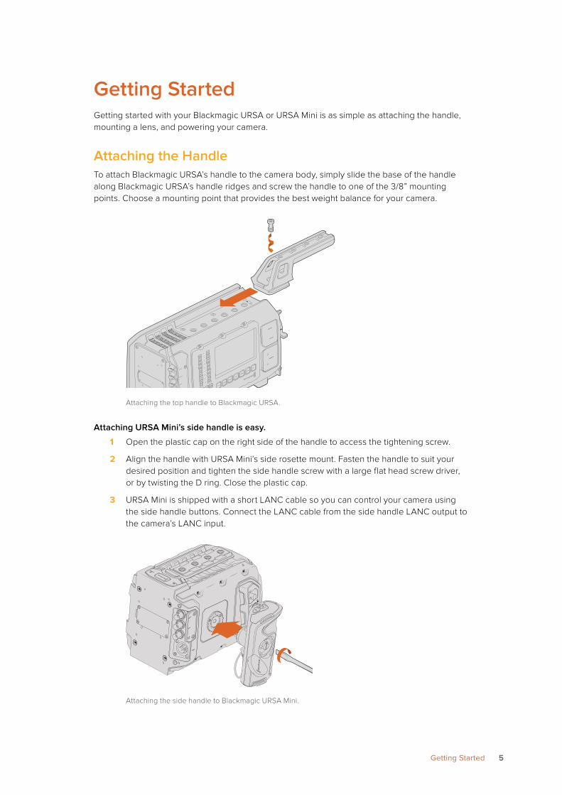
Attaching the HandleTo attach Blackmagic URSA’s handle to the camera body, simply slide the base of the handle along Blackmagic URSA’s handle ridges and screw the handle to one of the 3/8” mounting points. Choose a mounting point that provides the best weight balance for your camera.
Attaching the top handle to Blackmagic URSA.
Attaching URSA Mini’s side handle is easy.
1 Open the plastic cap on the right side of the handle to access the tightening screw.
2 Align the handle with URSA Mini’s side rosette mount. Fasten the handle to suit your desired position and tighten the side handle screw with a large flat head screw driver, or by twisting the D ring. Close the plastic cap.
3 URSA Mini is shipped with a short LANC cable so you can control your camera using the side handle buttons. Connect the LANC cable from the side handle LANC output to the camera’s LANC input.
Attaching the side handle to Blackmagic URSA Mini.
IRIS
SDI OUT
SDI OUT
REF IN
TIMECODE IN
L
R
TIMECODE O
UT
+12V
CH1
SOLO
CH1
MUTE
CH2
SOLO
CH2
MUTE
FOCUS
PEAK
DISP
AUDIO IN
12V OUT
SDI OUT
MENU
SLATE
0
-6
-12
-18
-24
-30
-36
-42
-48
SDI OUT
SDI IN
REF IN
TC IN
12V
55Getting Started
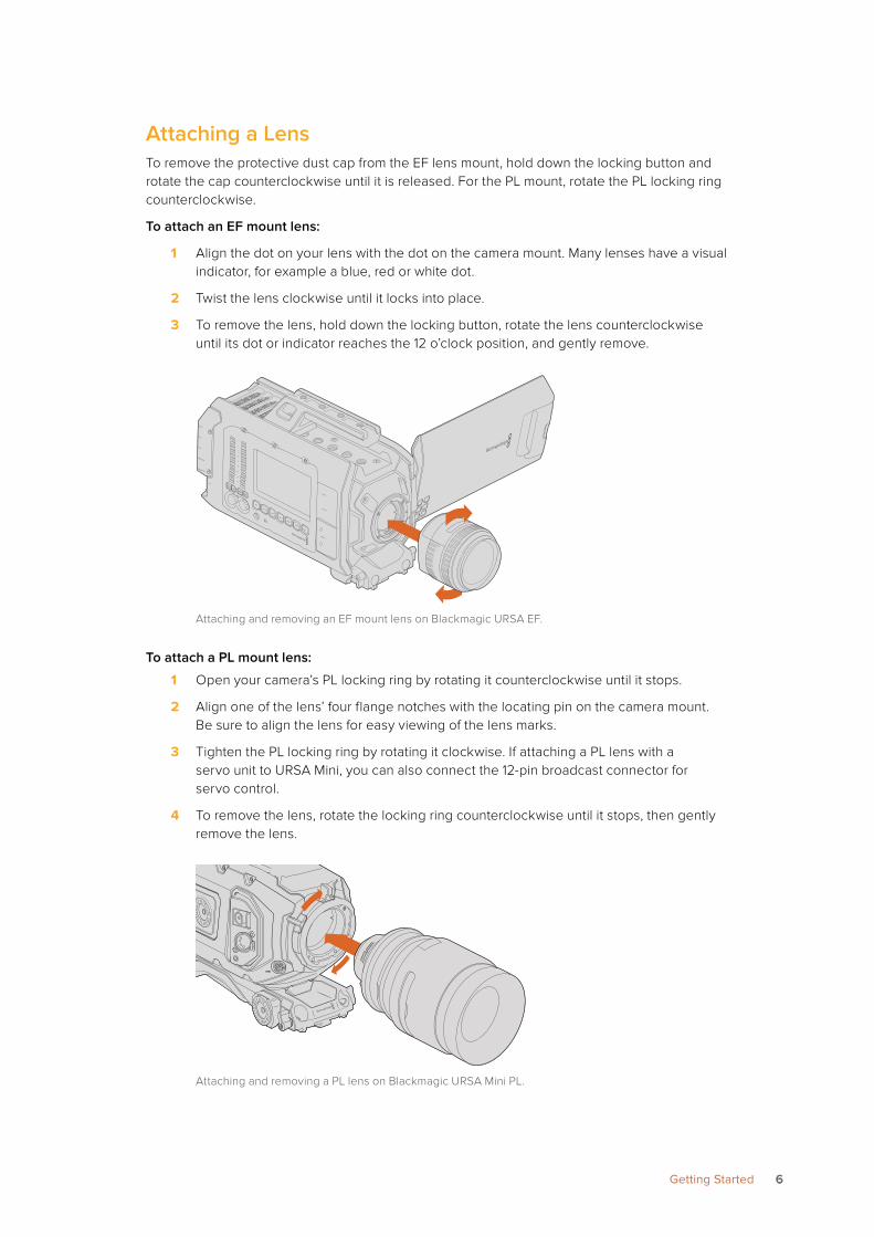
Attaching a LensTo remove the protective dust cap from the EF lens mount, hold down the locking button and rotate the cap counterclockwise until it is released. For the PL mount, rotate the PL locking ring counterclockwise.
To attach an EF mount lens:
1 Align the dot on your lens with the dot on the camera mount. Many lenses have a visual indicator, for example a blue, red or white dot.
2 Twist the lens clockwise until it locks into place.
3 To remove the lens, hold down the locking button, rotate the lens counterclockwise until its dot or indicator reaches the 12 o’clock position, and gently remove.
Attaching and removing an EF mount lens on Blackmagic URSA EF.
To attach a PL mount lens:
1 Open your camera’s PL locking ring by rotating it counterclockwise until it stops.
2 Align one of the lens’ four flange notches with the locating pin on the camera mount. Be sure to align the lens for easy viewing of the lens marks.
3 Tighten the PL locking ring by rotating it clockwise. If attaching a PL lens with a servo unit to URSA Mini, you can also connect the 12-pin broadcast connector for servo control.
4 To remove the lens, rotate the locking ring counterclockwise until it stops, then gently remove the lens.
Attaching and removing a PL lens on Blackmagic URSA Mini PL.
REF IN
+12V
TIMECODE IN
CH2MUTE
IRIS
FOCUS
PEAK
DISP
MENU
AUDIO IN
SDI OUT
+12V OUT
SLATE
TIMECODE OUT
0
-6
-12
-18
-24
-30
-36
-42
-48
SDI OUT
SDI IN
CH1SOLO
CH2SOLO
CH1MUTE
LENS
66Getting Started
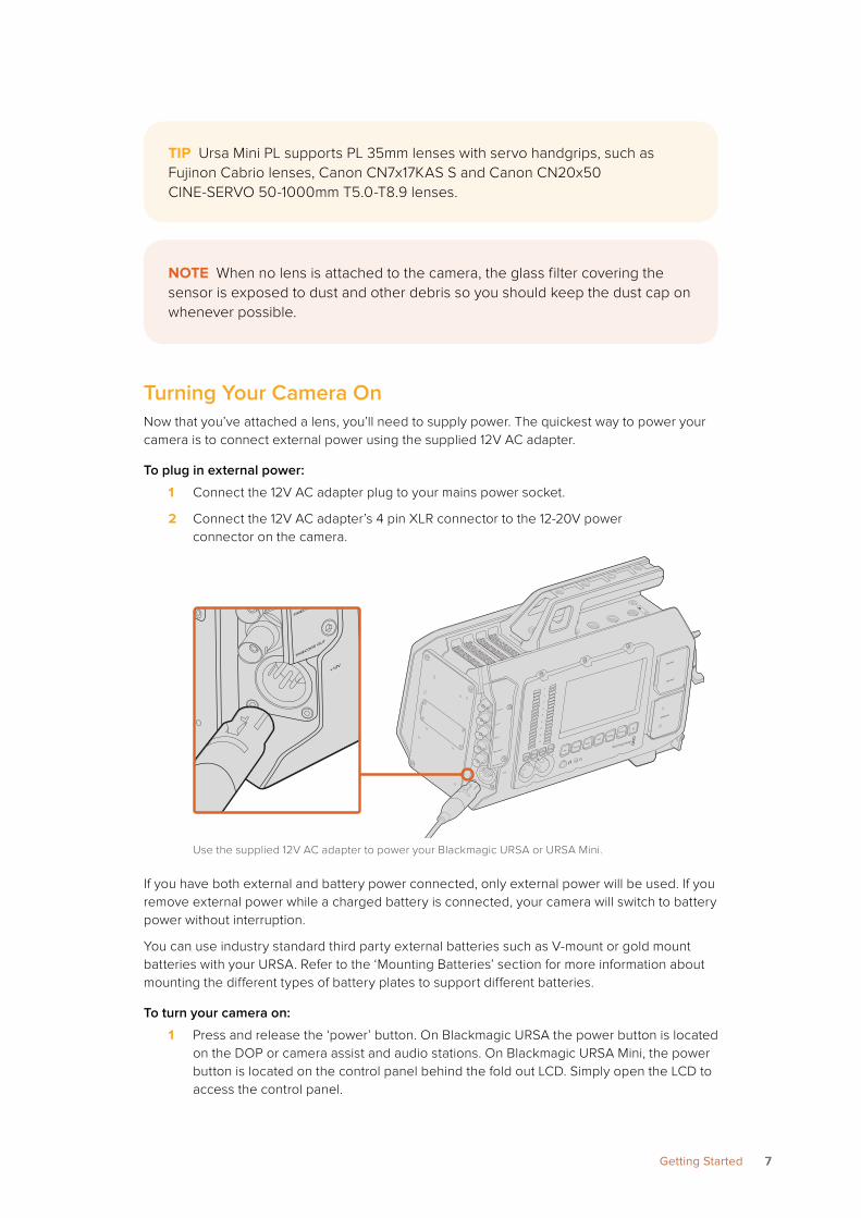
Turning Your Camera OnNow that you’ve attached a lens, you’ll need to supply power. The quickest way to power your camera is to connect external power using the supplied 12V AC adapter.
To plug in external power:
1 Connect the 12V AC adapter plug to your mains power socket.
2 Connect the 12V AC adapter’s 4 pin XLR connector to the 12-20V power connector on the camera.
Use the supplied 12V AC adapter to power your Blackmagic URSA or URSA Mini.
If you have both external and battery power connected, only external power will be used. If you remove external power while a charged battery is connected, your camera will switch to battery power without interruption.
You can use industry standard third party external batteries such as V-mount or gold mount batteries with your URSA. Refer to the ‘Mounting Batteries’ section for more information about mounting the different types of battery plates to support different batteries.
To turn your camera on:
1 Press and release the ‘power’ button. On Blackmagic URSA the power button is located on the DOP or camera assist and audio stations. On Blackmagic URSA Mini, the power button is located on the control panel behind the fold out LCD. Simply open the LCD to access the control panel.
TIP Ursa Mini PL supports PL 35mm lenses with servo handgrips, such as Fujinon Cabrio lenses, Canon CN7x17KAS S and Canon CN20x50 CINE-SERVO 50-1000mm T5.0-T8.9 lenses.
NOTE When no lens is attached to the camera, the glass filter covering the sensor is exposed to dust and other debris so you should keep the dust cap on whenever possible.
IRIS
SDI OUT
SDI IN
REF IN
TIMECODE IN
L
R
TIMECODE OUT
+12V
CH1
SOLO
CH1
MUTE
CH2
SOLO
CH2
MUTEFOCUS
PEAK
DISP
AUDIO IN
12V OUT
SDI OUT
MENU
SLATE
0
-6
-12
-18
-24
-30
-36
-42
-48
IRIS
SDI OUT
SDI IN
REF IN
TIMECODE IN
L
R
TIMECODE O
UT
+12V
CH1
SOLO
CH1
MUTE
CH2
SOLO
CH2
MUTE
FOCUS
PEAK
DISP
AUDIO IN
12V OUT
SDI OUT
MENU
SLATE
0
-6
-12
-18
-24
-30
-36
-42
-48
77Getting Started
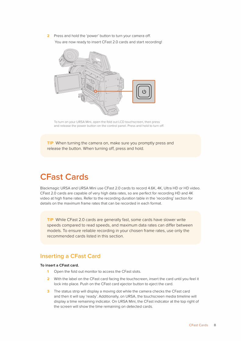
2 Press and hold the ‘power’ button to turn your camera off.
You are now ready to insert CFast 2.0 cards and start recording!
To turn on your URSA Mini, open the fold out LCD touchscreen, then press and release the power button on the control panel. Press and hold to turn off.
CFast CardsBlackmagic URSA and URSA Mini use CFast 2.0 cards to record 4.6K, 4K, Ultra HD or HD video. CFast 2.0 cards are capable of very high data rates, so are perfect for recording HD and 4K video at high frame rates. Refer to the recording duration table in the ‘recording’ section for details on the maximum frame rates that can be recorded in each format.
Inserting a CFast CardTo insert a CFast card.
1 Open the fold out monitor to access the CFast slots.
2 With the label on the CFast card facing the touchscreen, insert the card until you feel it lock into place. Push on the CFast card ejector button to eject the card.
3 The status strip will display a moving dot while the camera checks the CFast card and then it will say ‘ready’. Additionally, on URSA, the touchscreen media timeline will display a time remaining indicator. On URSA Mini, the CFast indicator at the top right of the screen will show the time remaining on detected cards.
IRIS
REC
FOCUSPEAK
DISP
MENU
TIP When turning the camera on, make sure you promptly press and release the button. When turning off, press and hold.
TIP While CFast 2.0 cards are generally fast, some cards have slower write speeds compared to read speeds, and maximum data rates can differ between models. To ensure reliable recording in your chosen frame rates, use only the recommended cards listed in this section.
8CFast Cards
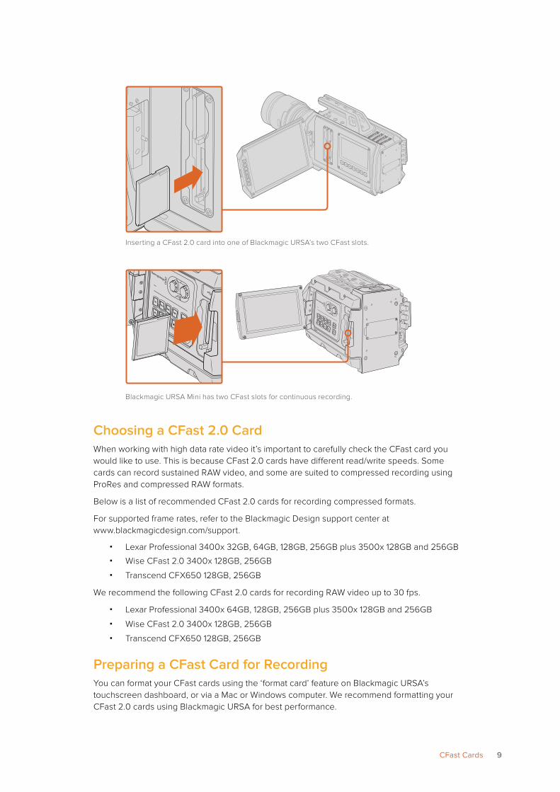
Inserting a CFast 2.0 card into one of Blackmagic URSA’s two CFast slots.
Blackmagic URSA Mini has two CFast slots for continuous recording.
Choosing a CFast 2.0 CardWhen working with high data rate video it’s important to carefully check the CFast card you would like to use. This is because CFast 2.0 cards have different read/write speeds. Some cards can record sustained RAW video, and some are suited to compressed recording using ProRes and compressed RAW formats.
Below is a list of recommended CFast 2.0 cards for recording compressed formats.
For supported frame rates, refer to the Blackmagic Design support center at www.blackmagicdesign.com/support.
� Lexar Professional 3400x 32GB, 64GB, 128GB, 256GB plus 3500x 128GB and 256GB
� Wise CFast 2.0 3400x 128GB, 256GB
� Transcend CFX650 128GB, 256GB
We recommend the following CFast 2.0 cards for recording RAW video up to 30 fps.
� Lexar Professional 3400x 64GB, 128GB, 256GB plus 3500x 128GB and 256GB
� Wise CFast 2.0 3400x 128GB, 256GB
� Transcend CFX650 128GB, 256GB
Preparing a CFast Card for RecordingYou can format your CFast cards using the ‘format card’ feature on Blackmagic URSA’s touchscreen dashboard, or via a Mac or Windows computer. We recommend formatting your CFast 2.0 cards using Blackmagic URSA for best performance.
IRIS
FOCUS
PEAK
DISP
MENU
SLATE
REC
ZOOM
DISP
PGM
IRIS
FOCUS
PEAK
DISP
MENU
SLATE
REC
ZOOM
DISP
PGM
IRIS
REC
FOCUSPEAK
DISP
MENU
IRIS
REC
FOCUSPEAK
DISP
MENU
9CFast Cards
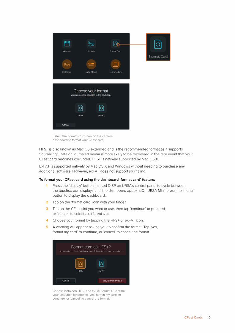
Select the ‘format card’ icon on the camera dashboard to format your CFast card.
HFS+ is also known as Mac OS extended and is the recommended format as it supports “journaling”. Data on journaled media is more likely to be recovered in the rare event that your CFast card becomes corrupted. HFS+ is natively supported by Mac OS X.
ExFAT is supported natively by Mac OS X and Windows without needing to purchase any additional software. However, exFAT does not support journaling.
To format your CFast card using the dashboard ‘format card’ feature:
1 Press the ‘display’ button marked DISP on URSA’s control panel to cycle between the touchscreen displays until the dashboard appears.On URSA Mini, press the ‘menu’ button to display the dashboard.
2 Tap on the ‘format card’ icon with your finger.
3 Tap on the CFast slot you want to use, then tap ‘continue’ to proceed, or ‘cancel’ to select a different slot.
4 Choose your format by tapping the HFS+ or exFAT icon.
5 A warning will appear asking you to confirm the format. Tap ‘yes, format my card’ to continue, or ‘cancel’ to cancel the format.
Choose between HFS+ and exFAT formats. Confirm your selection by tapping ‘yes, format my card’ to continue, or ‘cancel’ to cancel the format.
10CFast Cards
6 A progress bar shows you the status of the format. ‘Complete’ will appear when the format is done.
7 Tap the ‘done’ icon to return to the dashboard.
8 Press the ‘display’ button to exit the dashboard.
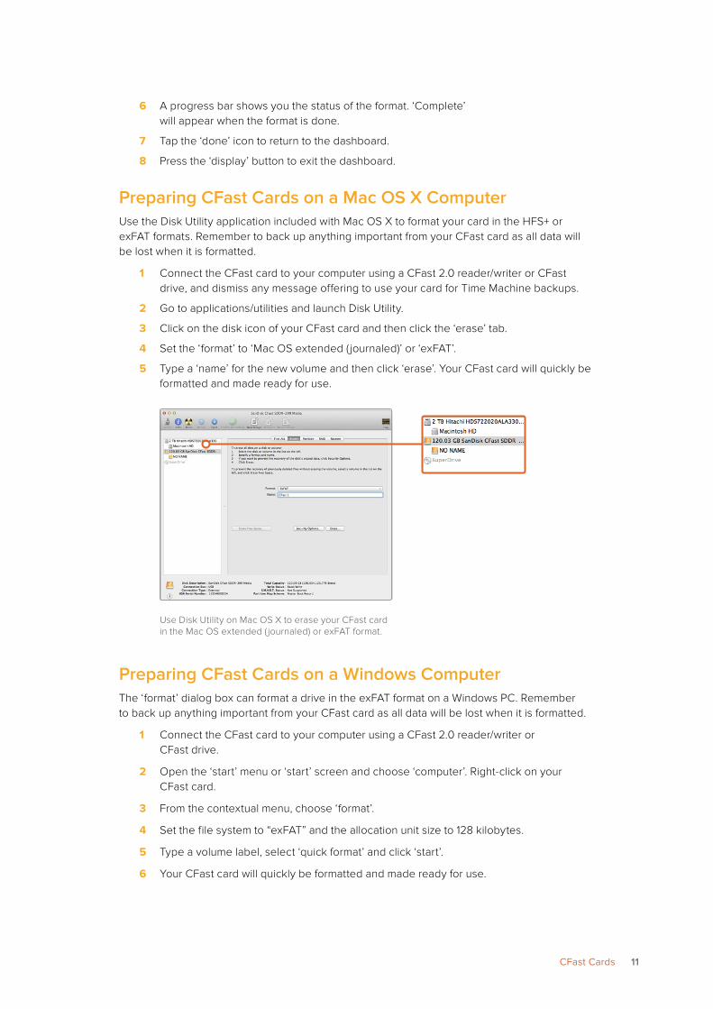
Preparing CFast Cards on a Mac OS X ComputerUse the Disk Utility application included with Mac OS X to format your card in the HFS+ or exFAT formats. Remember to back up anything important from your CFast card as all data will be lost when it is formatted.
1 Connect the CFast card to your computer using a CFast 2.0 reader/writer or CFast drive, and dismiss any message offering to use your card for Time Machine backups.
2 Go to applications/utilities and launch Disk Utility.
3 Click on the disk icon of your CFast card and then click the ‘erase’ tab.
4 Set the ‘format’ to ‘Mac OS extended ( journaled)’ or ‘exFAT’.
5 Type a ‘name’ for the new volume and then click ‘erase’. Your CFast card will quickly be formatted and made ready for use.
Use Disk Utility on Mac OS X to erase your CFast card in the Mac OS extended ( journaled) or exFAT format.
Preparing CFast Cards on a Windows ComputerThe ‘format’ dialog box can format a drive in the exFAT format on a Windows PC. Remember to back up anything important from your CFast card as all data will be lost when it is formatted.
1 Connect the CFast card to your computer using a CFast 2.0 reader/writer or CFast drive.
2 Open the ‘start’ menu or ‘start’ screen and choose ‘computer’. Right-click on your CFast card.
3 From the contextual menu, choose ‘format’.
4 Set the file system to “exFAT” and the allocation unit size to 128 kilobytes.
5 Type a volume label, select ‘quick format’ and click ‘start’.
6 Your CFast card will quickly be formatted and made ready for use.
11CFast Cards
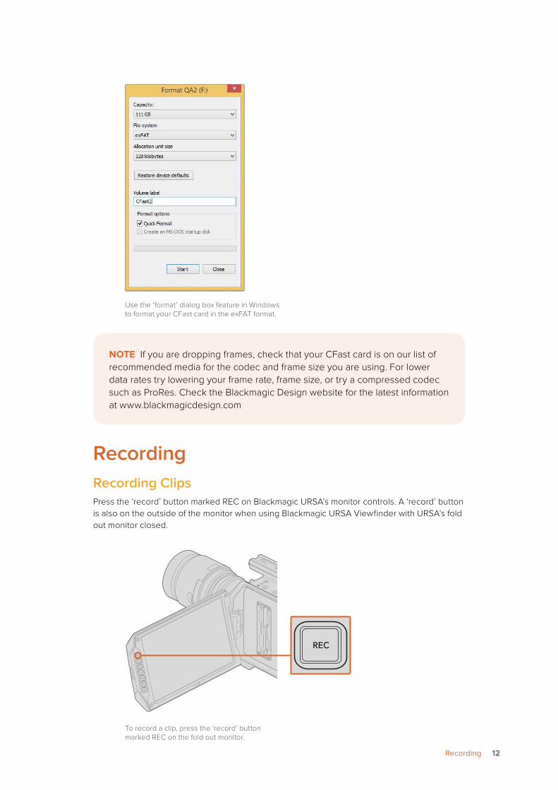
Use the ‘format’ dialog box feature in Windows to format your CFast card in the exFAT format.
Recording Recording ClipsPress the ‘record’ button marked REC on Blackmagic URSA’s monitor controls. A ‘record’ button is also on the outside of the monitor when using Blackmagic URSA Viewfinder with URSA’s fold out monitor closed.
To record a clip, press the ‘record’ button marked REC on the fold out monitor.
NOTE If you are dropping frames, check that your CFast card is on our list of recommended media for the codec and frame size you are using. For lower data rates try lowering your frame rate, frame size, or try a compressed codec such as ProRes. Check the Blackmagic Design website for the latest information at www.blackmagicdesign.com
IRIS
FOCUS
PEAK
DISP
MENU
SLATE
REC
ZOOM
DISP
PGM
REC REC
ZOOM
ZOOM
DISP
DISP
PGM
PGM
1212Recording
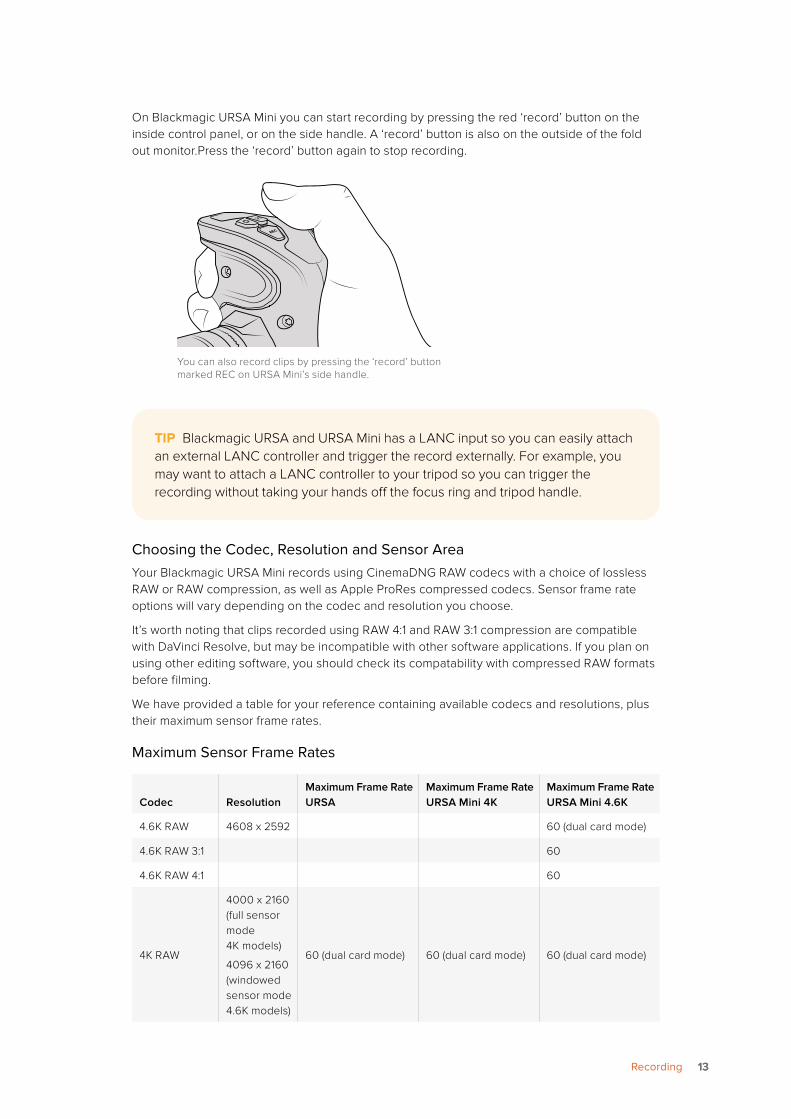
On Blackmagic URSA Mini you can start recording by pressing the red ‘record’ button on the inside control panel, or on the side handle. A ‘record’ button is also on the outside of the fold out monitor.Press the ‘record’ button again to stop recording.
You can also record clips by pressing the ‘record’ button marked REC on URSA Mini’s side handle.
Choosing the Codec, Resolution and Sensor AreaYour Blackmagic URSA Mini records using CinemaDNG RAW codecs with a choice of lossless RAW or RAW compression, as well as Apple ProRes compressed codecs. Sensor frame rate options will vary depending on the codec and resolution you choose.
It’s worth noting that clips recorded using RAW 4:1 and RAW 3:1 compression are compatible with DaVinci Resolve, but may be incompatible with other software applications. If you plan on using other editing software, you should check its compatability with compressed RAW formats before filming.
We have provided a table for your reference containing available codecs and resolutions, plus their maximum sensor frame rates.
Maximum Sensor Frame Rates
Codec ResolutionMaximum Frame Rate URSA
Maximum Frame Rate URSA Mini 4K
Maximum Frame Rate URSA Mini 4.6K
4.6K RAW 4608 x 2592 60 (dual card mode)
4.6K RAW 3:1 60
4.6K RAW 4:1 60
4K RAW
4000 x 2160 (full sensor mode 4K models)
4096 x 2160 (windowed sensor mode 4.6K models)
60 (dual card mode) 60 (dual card mode) 60 (dual card mode)
TIP Blackmagic URSA and URSA Mini has a LANC input so you can easily attach an external LANC controller and trigger the record externally. For example, you may want to attach a LANC controller to your tripod so you can trigger the recording without taking your hands off the focus ring and tripod handle.
1313Recording
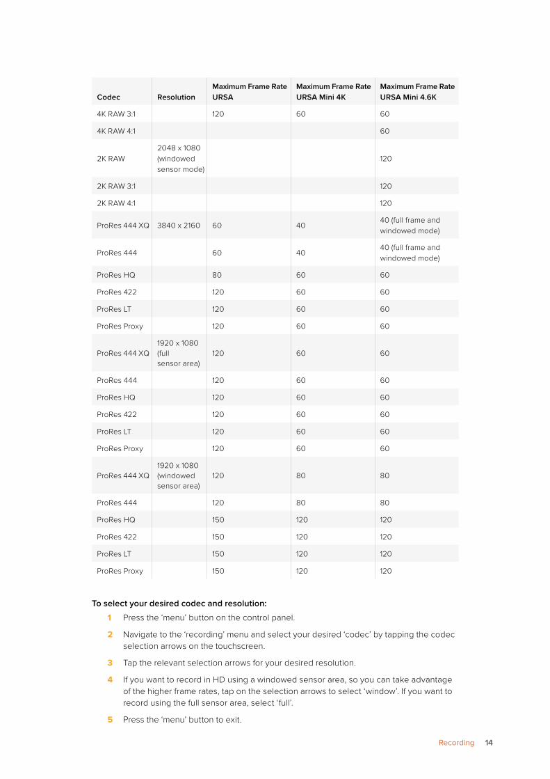
Codec ResolutionMaximum Frame Rate URSA
Maximum Frame Rate URSA Mini 4K
Maximum Frame Rate URSA Mini 4.6K
4K RAW 3:1 120 60 60
4K RAW 4:1 60
2K RAW2048 x 1080 (windowed sensor mode)
120
2K RAW 3:1 120
2K RAW 4:1 120
ProRes 444 XQ 3840 x 2160 60 4040 (full frame and windowed mode)
ProRes 444 60 4040 (full frame and windowed mode)
ProRes HQ 80 60 60
ProRes 422 120 60 60
ProRes LT 120 60 60
ProRes Proxy 120 60 60
ProRes 444 XQ1920 x 1080 (full sensor area)
120 60 60
ProRes 444 120 60 60
ProRes HQ 120 60 60
ProRes 422 120 60 60
ProRes LT 120 60 60
ProRes Proxy 120 60 60
ProRes 444 XQ1920 x 1080 (windowed sensor area)
120 80 80
ProRes 444 120 80 80
ProRes HQ 150 120 120
ProRes 422 150 120 120
ProRes LT 150 120 120
ProRes Proxy 150 120 120
To select your desired codec and resolution:
1 Press the ‘menu’ button on the control panel.
2 Navigate to the ‘recording’ menu and select your desired ‘codec’ by tapping the codec selection arrows on the touchscreen.
3 Tap the relevant selection arrows for your desired resolution.
4 If you want to record in HD using a windowed sensor area, so you can take advantage of the higher frame rates, tap on the selection arrows to select ‘window’. If you want to record using the full sensor area, select ‘full’.
5 Press the ‘menu’ button to exit.
1414Recording
Recording Formats and Project Frame RatesAfter setting your codec and resolution, you should set your ‘project’ and ‘sensor’ frame rates. Refer to the ‘recording settings’ section in this manual for more information about frame rates. The project framerates available for all URSA and URSA Mini cameras are as follows:
23.98, 24, 25, 29.97, 30, 50, 59.94, and 60 frames per second.
The only exception is URSA Mini, which offers project frame rates of 23.98, 24, 25, and 30 when using ProRes 444 XQ or ProRes 444 at Ultra HD resolution. For uncompressed 4.6K and 4K RAW, framerates above 30 fps use dual card mode on all URSA and URSA Mini cameras.
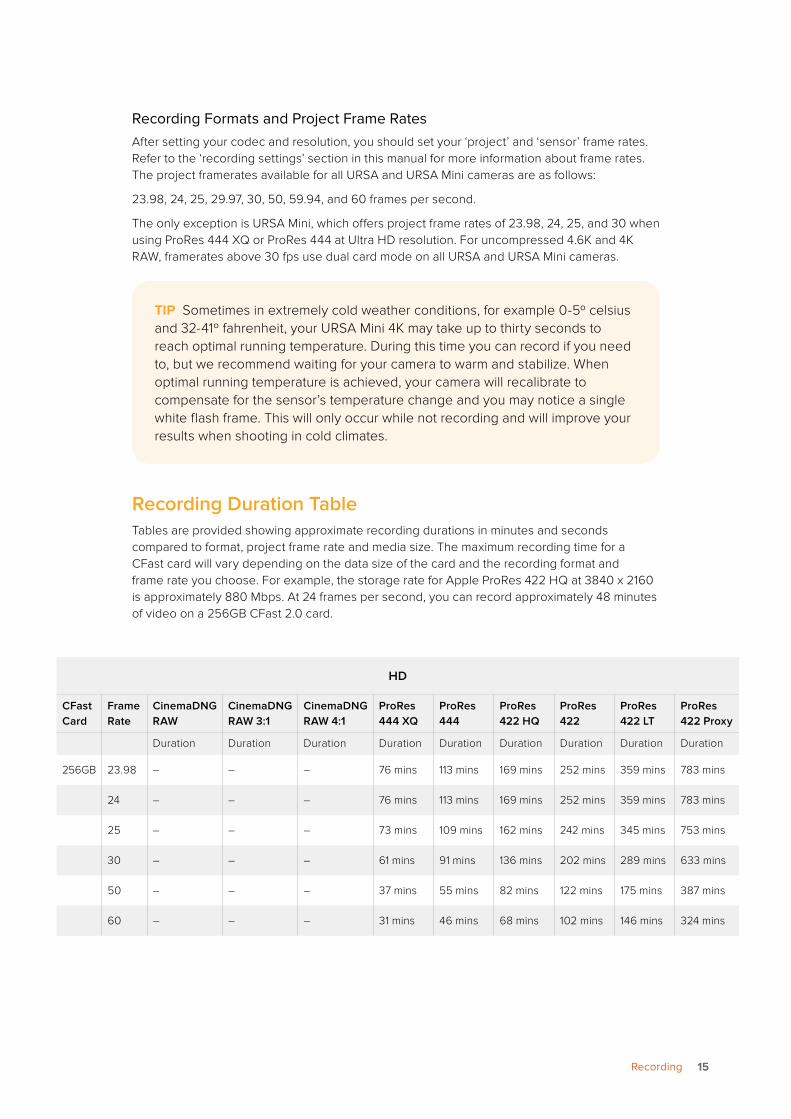
Recording Duration TableTables are provided showing approximate recording durations in minutes and seconds compared to format, project frame rate and media size. The maximum recording time for a CFast card will vary depending on the data size of the card and the recording format and frame rate you choose. For example, the storage rate for Apple ProRes 422 HQ at 3840 x 2160 is approximately 880 Mbps. At 24 frames per second, you can record approximately 48 minutes of video on a 256GB CFast 2.0 card.
TIP Sometimes in extremely cold weather conditions, for example 0-5º celsius and 32-41º fahrenheit, your URSA Mini 4K may take up to thirty seconds to reach optimal running temperature. During this time you can record if you need to, but we recommend waiting for your camera to warm and stabilize. When optimal running temperature is achieved, your camera will recalibrate to compensate for the sensor’s temperature change and you may notice a single white flash frame. This will only occur while not recording and will improve your results when shooting in cold climates.
HD
CFast Card
Frame Rate
CinemaDNG RAW
CinemaDNG RAW 3:1
CinemaDNG RAW 4:1
ProRes 444 XQ
ProRes 444
ProRes 422 HQ
ProRes 422
ProRes 422 LT
ProRes 422 Proxy
Duration Duration Duration Duration Duration Duration Duration Duration Duration
256GB 23.98 – – – 76 mins 113 mins 169 mins 252 mins 359 mins 783 mins
24 – – – 76 mins 113 mins 169 mins 252 mins 359 mins 783 mins
25 – – – 73 mins 109 mins 162 mins 242 mins 345 mins 753 mins
30 – – – 61 mins 91 mins 136 mins 202 mins 289 mins 633 mins
50 – – – 37 mins 55 mins 82 mins 122 mins 175 mins 387 mins
60 – – – 31 mins 46 mins 68 mins 102 mins 146 mins 324 mins
1515Recording
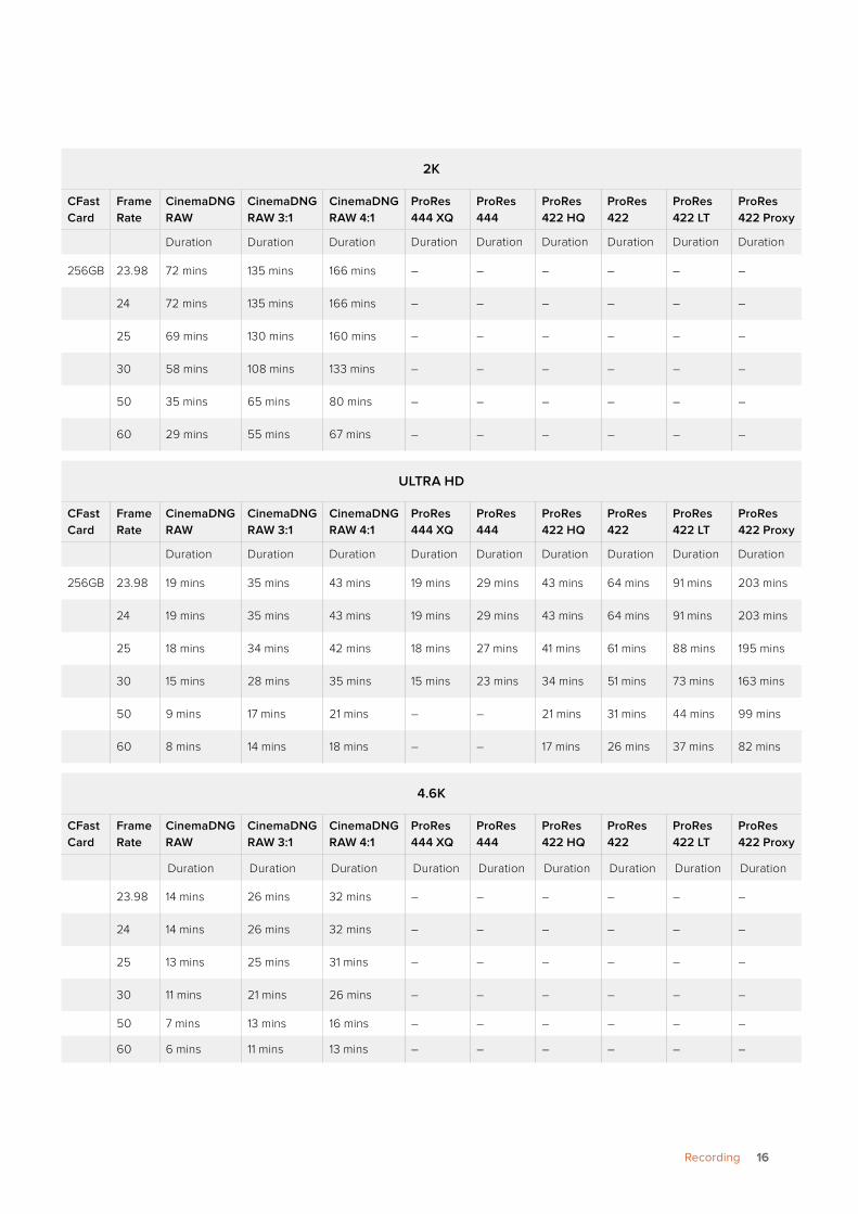
2K
CFast Card
Frame Rate
CinemaDNG RAW
CinemaDNG RAW 3:1
CinemaDNG RAW 4:1
ProRes 444 XQ
ProRes 444
ProRes 422 HQ
ProRes 422
ProRes 422 LT
ProRes 422 Proxy
Duration Duration Duration Duration Duration Duration Duration Duration Duration
256GB 23.98 72 mins 135 mins 166 mins – – – – – –
24 72 mins 135 mins 166 mins – – – – – –
25 69 mins 130 mins 160 mins – – – – – –
30 58 mins 108 mins 133 mins – – – – – –
50 35 mins 65 mins 80 mins – – – – – –
60 29 mins 55 mins 67 mins – – – – – –
ULTRA HD
CFast Card
Frame Rate
CinemaDNG RAW
CinemaDNG RAW 3:1
CinemaDNG RAW 4:1
ProRes 444 XQ
ProRes 444
ProRes 422 HQ
ProRes 422
ProRes 422 LT
ProRes 422 Proxy
Duration Duration Duration Duration Duration Duration Duration Duration Duration
256GB 23.98 19 mins 35 mins 43 mins 19 mins 29 mins 43 mins 64 mins 91 mins 203 mins
24 19 mins 35 mins 43 mins 19 mins 29 mins 43 mins 64 mins 91 mins 203 mins
25 18 mins 34 mins 42 mins 18 mins 27 mins 41 mins 61 mins 88 mins 195 mins
30 15 mins 28 mins 35 mins 15 mins 23 mins 34 mins 51 mins 73 mins 163 mins
50 9 mins 17 mins 21 mins – – 21 mins 31 mins 44 mins 99 mins
60 8 mins 14 mins 18 mins – – 17 mins 26 mins 37 mins 82 mins
4.6K
CFast Card
Frame Rate
CinemaDNG RAW
CinemaDNG RAW 3:1
CinemaDNG RAW 4:1
ProRes 444 XQ
ProRes 444
ProRes 422 HQ
ProRes 422
ProRes 422 LT
ProRes 422 Proxy
Duration Duration Duration Duration Duration Duration Duration Duration Duration
23.98 14 mins 26 mins 32 mins – – – – – –
24 14 mins 26 mins 32 mins – – – – – –
25 13 mins 25 mins 31 mins – – – – – –
30 11 mins 21 mins 26 mins – – – – – –
50 7 mins 13 mins 16 mins – – – – – –
60 6 mins 11 mins 13 mins – – – – – –
1616Recording
Trigger RecordYour URSA Mini automatically sends a signal via the SDI outputs that will trigger recording when connected to equipment that supports the SDI trigger record feature, such as Blackmagic Video Assist. This means when you press record on your camera, your external SDI equipment will also start recording, then will stop recording when you press record again.
You will also need to set your equipment to enable SDI trigger recording to make sure it responds to the trigger signal from your URSA Mini. If your SDI equipment supports SDI trigger recording, it can usually be enabled using your SDI equipment’s settings menu.
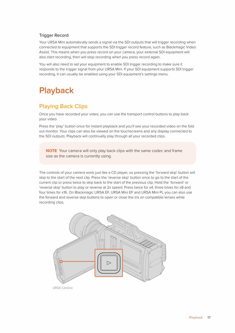
Playback
Playing Back ClipsOnce you have recorded your video, you can use the transport control buttons to play back your video.
Press the ‘play’ button once for instant playback and you’ll see your recorded video on the fold out monitor. Your clips can also be viewed on the touchscreens and any display connected to the SDI outputs. Playback will continually play through all your recorded clips.
The controls of your camera work just like a CD player, so pressing the ‘forward skip’ button will skip to the start of the next clip. Press the ‘reverse skip’ button once to go to the start of the current clip or press twice to skip back to the start of the previous clip. Hold the ‘forward’ or ‘reverse skip’ button to play or reverse at 2x speed. Press twice for x4, three times for x8 and four times for x16. On Blackmagic URSA EF, URSA Mini EF and URSA Mini PL you can also use the forward and reverse skip buttons to open or close the iris on compatible lenses while recording clips.
URSA Camera
NOTE Your camera will only play back clips with the same codec and frame size as the camera is currently using.
IRIS
FOCUS
PEAK
DISP
MENU
SLATE
REC
ZOOM
DISP
PGM
REC REC
ZOOM
ZOOM
DISP
DISP
PGM
PGM
1717Playback
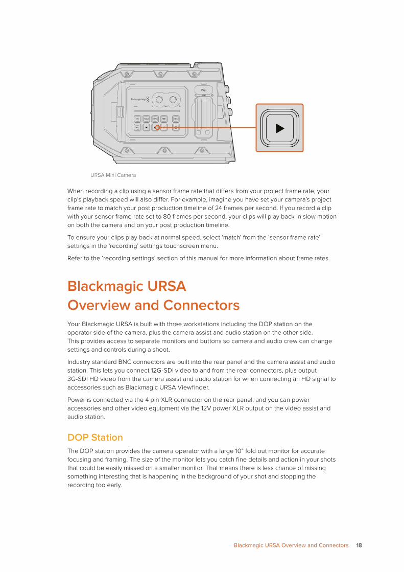
URSA Mini Camera
When recording a clip using a sensor frame rate that differs from your project frame rate, your clip’s playback speed will also differ. For example, imagine you have set your camera’s project frame rate to match your post production timeline of 24 frames per second. If you record a clip with your sensor frame rate set to 80 frames per second, your clips will play back in slow motion on both the camera and on your post production timeline.
To ensure your clips play back at normal speed, select ‘match’ from the ‘sensor frame rate’ settings in the ‘recording’ settings touchscreen menu.
Refer to the ‘recording settings’ section of this manual for more information about frame rates.
Blackmagic URSA Overview and ConnectorsYour Blackmagic URSA is built with three workstations including the DOP station on the operator side of the camera, plus the camera assist and audio station on the other side. This provides access to separate monitors and buttons so camera and audio crew can change settings and controls during a shoot.
Industry standard BNC connectors are built into the rear panel and the camera assist and audio station. This lets you connect 12G-SDI video to and from the rear connectors, plus output 3G-SDI HD video from the camera assist and audio station for when connecting an HD signal to accessories such as Blackmagic URSA Viewfinder.
Power is connected via the 4 pin XLR connector on the rear panel, and you can power accessories and other video equipment via the 12V power XLR output on the video assist and audio station.
DOP StationThe DOP station provides the camera operator with a large 10” fold out monitor for accurate focusing and framing. The size of the monitor lets you catch fine details and action in your shots that could be easily missed on a smaller monitor. That means there is less chance of missing something interesting that is happening in the background of your shot and stopping the recording too early.
1 2CFAST
1 2CFAST
1818Blackmagic URSA Overview and Connectors
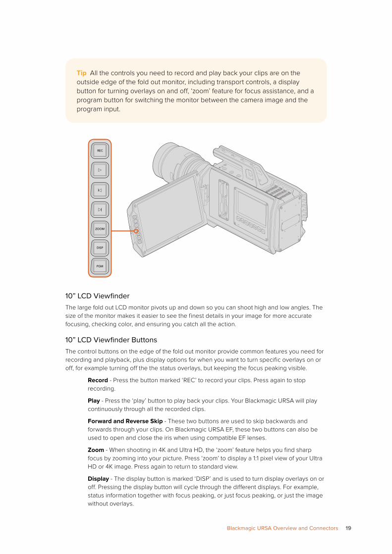
10” LCD ViewfinderThe large fold out LCD monitor pivots up and down so you can shoot high and low angles. The size of the monitor makes it easier to see the finest details in your image for more accurate focusing, checking color, and ensuring you catch all the action.
10” LCD Viewfinder ButtonsThe control buttons on the edge of the fold out monitor provide common features you need for recording and playback, plus display options for when you want to turn specific overlays on or off, for example turning off the the status overlays, but keeping the focus peaking visible.
Record - Press the button marked ‘REC’ to record your clips. Press again to stop recording.
Play - Press the ‘play’ button to play back your clips. Your Blackmagic URSA will play continuously through all the recorded clips.
Forward and Reverse Skip - These two buttons are used to skip backwards and forwards through your clips. On Blackmagic URSA EF, these two buttons can also be used to open and close the iris when using compatible EF lenses.
Zoom - When shooting in 4K and Ultra HD, the ‘zoom’ feature helps you find sharp focus by zooming into your picture. Press ‘zoom’ to display a 1:1 pixel view of your Ultra HD or 4K image. Press again to return to standard view.
Display - The display button is marked ‘DISP’ and is used to turn display overlays on or off. Pressing the display button will cycle through the different displays. For example, status information together with focus peaking, or just focus peaking, or just the image without overlays.
Tip All the controls you need to record and play back your clips are on the outside edge of the fold out monitor, including transport controls, a display button for turning overlays on and off, ‘zoom’ feature for focus assistance, and a program button for switching the monitor between the camera image and the program input.
IRIS
FOCUS
PEAK
DISP
MENU
SLATE
REC
ZOOM
DISP
PGM
REC REC
ZOOM
ZOOM
DISP
DISP
PGM
PGM
1919Blackmagic URSA Overview and Connectors
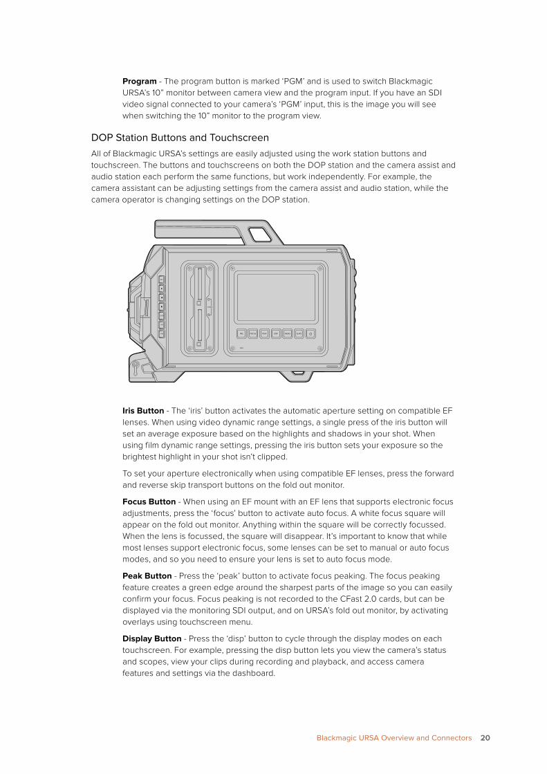
Program - The program button is marked ‘PGM’ and is used to switch Blackmagic URSA’s 10” monitor between camera view and the program input. If you have an SDI video signal connected to your camera’s ‘PGM’ input, this is the image you will see when switching the 10” monitor to the program view.
DOP Station Buttons and TouchscreenAll of Blackmagic URSA’s settings are easily adjusted using the work station buttons and touchscreen. The buttons and touchscreens on both the DOP station and the camera assist and audio station each perform the same functions, but work independently. For example, the camera assistant can be adjusting settings from the camera assist and audio station, while the camera operator is changing settings on the DOP station.
Iris Button - The ‘iris’ button activates the automatic aperture setting on compatible EF lenses. When using video dynamic range settings, a single press of the iris button will set an average exposure based on the highlights and shadows in your shot. When using film dynamic range settings, pressing the iris button sets your exposure so the brightest highlight in your shot isn’t clipped.
To set your aperture electronically when using compatible EF lenses, press the forward and reverse skip transport buttons on the fold out monitor.
Focus Button - When using an EF mount with an EF lens that supports electronic focus adjustments, press the ‘focus’ button to activate auto focus. A white focus square will appear on the fold out monitor. Anything within the square will be correctly focussed. When the lens is focussed, the square will disappear. It’s important to know that while most lenses support electronic focus, some lenses can be set to manual or auto focus modes, and so you need to ensure your lens is set to auto focus mode.
Peak Button - Press the ‘peak’ button to activate focus peaking. The focus peaking feature creates a green edge around the sharpest parts of the image so you can easily confirm your focus. Focus peaking is not recorded to the CFast 2.0 cards, but can be displayed via the monitoring SDI output, and on URSA’s fold out monitor, by activating overlays using touchscreen menu.
Display Button - Press the ‘disp’ button to cycle through the display modes on each touchscreen. For example, pressing the disp button lets you view the camera’s status and scopes, view your clips during recording and playback, and access camera features and settings via the dashboard.
REC
ZOOM
DISP
PGM
1
CFAST
IRIS
FOCUS
REC
IRIS
FOCUS PEAK DISP MENU SLATE
2
IRIS
SDI OUT
0
-6
-12
-18
-24
-30
-36
-42
-48
L R
SDI IN
REF IN
TIMECODE IN
TIMECODE OUT
12V
CH1SOLO
CH1MUTE
CH2MUTE
CH2SOLO
FOCUS PEAK DISP MENU SLATE
PU
SHP
USH
PU
SH
2020Blackmagic URSA Overview and Connectors
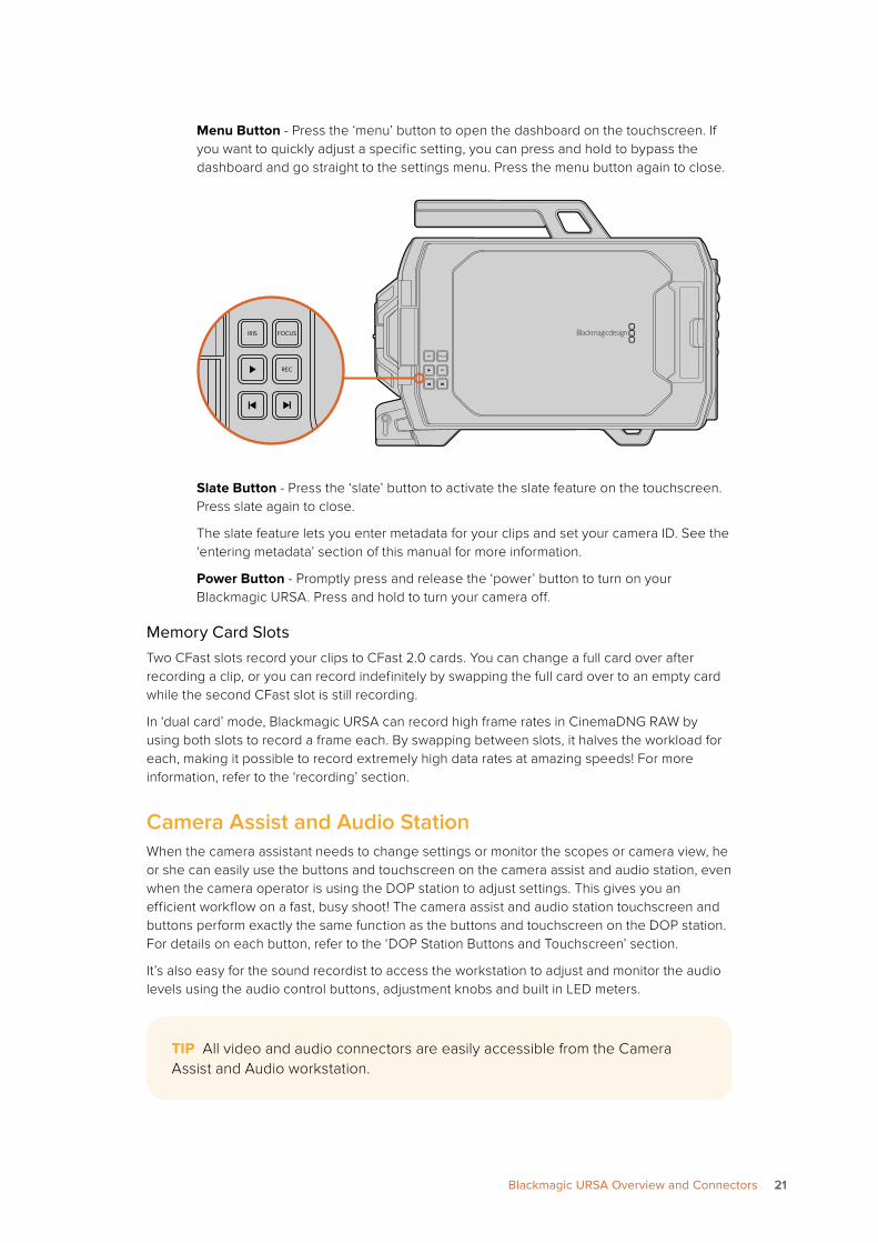
Menu Button - Press the ‘menu’ button to open the dashboard on the touchscreen. If you want to quickly adjust a specific setting, you can press and hold to bypass the dashboard and go straight to the settings menu. Press the menu button again to close.
Slate Button - Press the ‘slate’ button to activate the slate feature on the touchscreen. Press slate again to close.
The slate feature lets you enter metadata for your clips and set your camera ID. See the ‘entering metadata’ section of this manual for more information.
Power Button - Promptly press and release the ‘power’ button to turn on your Blackmagic URSA. Press and hold to turn your camera off.
Memory Card SlotsTwo CFast slots record your clips to CFast 2.0 cards. You can change a full card over after recording a clip, or you can record indefinitely by swapping the full card over to an empty card while the second CFast slot is still recording.
In ‘dual card’ mode, Blackmagic URSA can record high frame rates in CinemaDNG RAW by using both slots to record a frame each. By swapping between slots, it halves the workload for each, making it possible to record extremely high data rates at amazing speeds! For more information, refer to the ‘recording’ section.
Camera Assist and Audio StationWhen the camera assistant needs to change settings or monitor the scopes or camera view, he or she can easily use the buttons and touchscreen on the camera assist and audio station, even when the camera operator is using the DOP station to adjust settings. This gives you an efficient workflow on a fast, busy shoot! The camera assist and audio station touchscreen and buttons perform exactly the same function as the buttons and touchscreen on the DOP station. For details on each button, refer to the ‘DOP Station Buttons and Touchscreen’ section.
It’s also easy for the sound recordist to access the workstation to adjust and monitor the audio levels using the audio control buttons, adjustment knobs and built in LED meters.
REC
ZOOM
DISP
PGM
1
CFAST
IRIS
FOCUS
REC
IRIS
FOCUS PEAK DISP MENU SLATE
2
IRIS
SDI OUT
0
-6
-12
-18
-24
-30
-36
-42
-48
L R
SDI IN
REF IN
TIMECODE IN
TIMECODE OUT
12V
CH1SOLO
CH1MUTE
CH2MUTE
CH2SOLO
FOCUS PEAK DISP MENU SLATE
PU
SHP
USH
PU
SH
REC
ZOOM
DISP
PGM
1
CFAST
IRIS
FOCUS
REC
IRIS
FOCUS PEAK DISP MENU SLATE
2
IRIS
SDI OUT
0
-6
-12
-18
-24
-30
-36
-42
-48
L R
SDI IN
REF IN
TIMECODE IN
TIMECODE OUT
12V
CH1SOLO
CH1MUTE
CH2MUTE
CH2SOLO
FOCUS PEAK DISP MENU SLATE
PU
SHP
USH
PU
SH
TIP All video and audio connectors are easily accessible from the Camera Assist and Audio workstation.
2121Blackmagic URSA Overview and Connectors
Audio Level Adjustment Knobs
Turn each knob clockwise or counterclockwise to increase or decrease the recording level for each channel of audio. As you adjust each knob you’ll see the corresponding audio meters respond.
Audio Meters
The audio meters display the strength of your recorded audio. If your audio levels rise too high, your audio peaks can be clipped and you will hear distortion in your audio.
CH SOLO and MUTE Buttons
During recording and playback, these buttons let you monitor your ch 1 and ch 2 stereo audio channels independently via headphones. For example, to monitor only ch 1 audio, press the ‘ch 1 solo’ button or the ‘ch 2 mute’ button. Press the button again to monitor both channels.
CH 1 SOLO Button
To monitor ch 1 only, press the ‘ch 1 solo’ button.
CH 1 MUTE Button
To mute the audio on channel 1 and monitor only channel 2, press the ‘ch 1 mute’ button.
CH 2 SOLO Button
To monitor ch 2 only, press the ‘ch 2 solo’ button.
CH 2 MUTE Button
To mute the audio on channel 2 and monitor only channel 1, press the ‘ch 2 mute’ button.
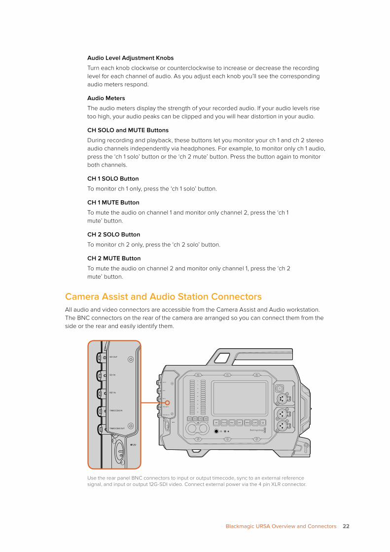
Camera Assist and Audio Station ConnectorsAll audio and video connectors are accessible from the Camera Assist and Audio workstation. The BNC connectors on the rear of the camera are arranged so you can connect them from the side or the rear and easily identify them.
Use the rear panel BNC connectors to input or output timecode, sync to an external reference signal, and input or output 12G-SDI video. Connect external power via the 4 pin XLR connector.
REC
ZOOM
DISP
PGM
1
CFAST
IRIS
FOCUS
REC
IRIS
FOCUS PEAK DISP MENU SLATE
2
IRIS
SDI OUT
0
-6
-12
-18
-24
-30
-36
-42
-48
L R
SDI IN
REF IN
TIMECODE IN
TIMECODE OUT
12V
CH1SOLO
CH1MUTE
CH2MUTE
CH2SOLO
FOCUS PEAK DISP MENU SLATE
PU
SHP
USH
PU
SH
REC
ZOOM
DISP
PGM
1
CFAST
IRIS
FOCUS
REC
IRIS
FOCUS PEAK DISP MENU SLATE
2
IRIS
SDI OUT
0
-6
-12
-18
-24
-30
-36
-42
-48
L R
SDI IN
REF IN
TIMECODE IN
TIMECODE OUT
12V
CH1SOLO
CH1MUTE
CH2MUTE
CH2SOLO
FOCUS PEAK DISP MENU SLATE
PU
SHP
USH
PU
SH
2222Blackmagic URSA Overview and Connectors
SDI Out
Blackmagic URSA’s 12G-SDI output is used to send HD and Ultra HD video to SDI equipment such as routers, monitors, SDI capture devices, and broadcast switchers.
SDI In
When connecting Blackmagic URSA to a switcher for live production, connect the switcher’s program output to Blackmagic URSA’s 12G-SDI input. Now you can view the switcher’s program output by pressing the PGM button on the fold out monitor. Your camera’s program input can also be used to connect to the playback output of an external recorder. You can then select between the camera image and the feed from the external recorder by pressing the PGM button.
REF In
Synchronize Blackmagic URSA to a common reference signal, such as black burst or tri-level sync, by connecting to the ‘ref in’ BNC connector. This lets you sync Blackmagic URSA to other SDI video equipment, for example, when using multiple cameras connected to a switcher.
Timecode In
Record timecode from other professional audio and video equipment, such as audio mixers and clapper boards by connecting them to Blackmagic URSA’s ‘timecode in’ BNC connector. This ensures audio and picture can be easily synchronized during post production.
Timecode Out
Send timecode from Blackmagic URSA to other professional video equipment by connecting to the ‘timecode out’ BNC connector.
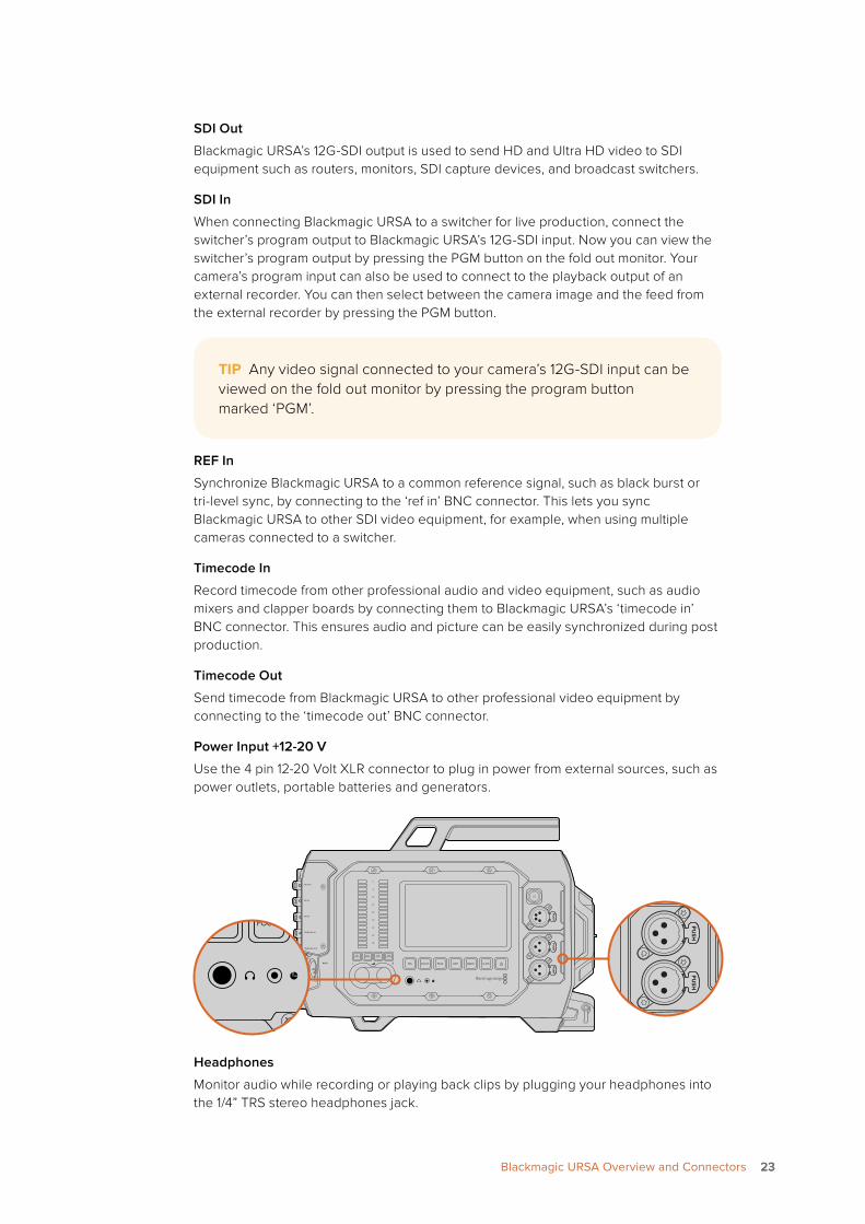
Power Input +12-20 V
Use the 4 pin 12-20 Volt XLR connector to plug in power from external sources, such as power outlets, portable batteries and generators.
Headphones
Monitor audio while recording or playing back clips by plugging your headphones into the 1/4” TRS stereo headphones jack.
TIP Any video signal connected to your camera’s 12G-SDI input can be viewed on the fold out monitor by pressing the program button marked ‘PGM’.
REC
ZOOM
DISP
PGM
1
CFAST
IRIS
FOCUS
REC
IRIS
FOCUS PEAK DISP MENU SLATE
2
IRIS
SDI OUT
0
-6
-12
-18
-24
-30
-36
-42
-48
L R
SDI IN
REF IN
TIMECODE IN
TIMECODE OUT
12V
CH1SOLO
CH1MUTE
CH2MUTE
CH2SOLO
FOCUS PEAK DISP MENU SLATE
PU
SHP
USH
PU
SH
REC
ZOOM
DISP
PGM
1
CFAST
IRIS
FOCUS
REC
IRIS
FOCUS PEAK DISP MENU SLATE
2
IRIS
SDI OUT
0
-6
-12
-18
-24
-30
-36
-42
-48
L R
SDI IN
REF IN
TIMECODE IN
TIMECODE OUT
12V
CH1SOLO
CH1MUTE
CH2MUTE
CH2SOLO
FOCUS PEAK DISP MENU SLATE
PU
SHP
USH
PU
SH
REC
ZOOM
DISP
PGM
1
CFAST
IRIS
FOCUS
REC
IRIS
FOCUS PEAK DISP MENU SLATE
2
IRIS
SDI OUT
0
-6
-12
-18
-24
-30
-36
-42
-48
L R
SDI IN
REF IN
TIMECODE IN
TIMECODE OUT
12V
CH1SOLO
CH1MUTE
CH2MUTE
CH2SOLO
FOCUS PEAK DISP MENU SLATE
PU
SHP
USH
PU
SH
2323Blackmagic URSA Overview and Connectors
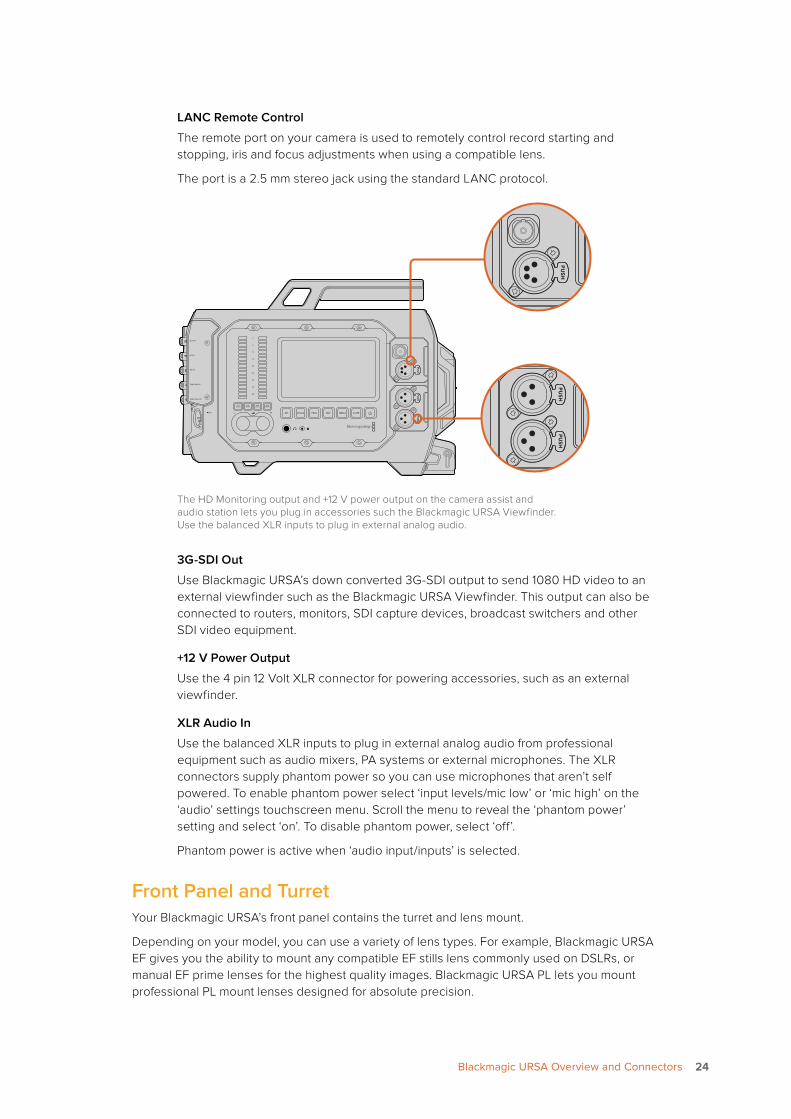
LANC Remote Control
The remote port on your camera is used to remotely control record starting and stopping, iris and focus adjustments when using a compatible lens.
The port is a 2.5 mm stereo jack using the standard LANC protocol.
The HD Monitoring output and +12 V power output on the camera assist and audio station lets you plug in accessories such the Blackmagic URSA Viewfinder. Use the balanced XLR inputs to plug in external analog audio.
3G-SDI Out
Use Blackmagic URSA’s down converted 3G-SDI output to send 1080 HD video to an external viewfinder such as the Blackmagic URSA Viewfinder. This output can also be connected to routers, monitors, SDI capture devices, broadcast switchers and other SDI video equipment.
+12 V Power Output
Use the 4 pin 12 Volt XLR connector for powering accessories, such as an external viewfinder.
XLR Audio In
Use the balanced XLR inputs to plug in external analog audio from professional equipment such as audio mixers, PA systems or external microphones. The XLR connectors supply phantom power so you can use microphones that aren’t self powered. To enable phantom power select ‘input levels/mic low’ or ‘mic high’ on the ‘audio’ settings touchscreen menu. Scroll the menu to reveal the ‘phantom power’ setting and select ‘on’. To disable phantom power, select ‘off’.
Phantom power is active when ‘audio input/inputs’ is selected.
Front Panel and TurretYour Blackmagic URSA’s front panel contains the turret and lens mount.
Depending on your model, you can use a variety of lens types. For example, Blackmagic URSA EF gives you the ability to mount any compatible EF stills lens commonly used on DSLRs, or manual EF prime lenses for the highest quality images. Blackmagic URSA PL lets you mount professional PL mount lenses designed for absolute precision.
REC
ZOOM
DISP
PGM
1
CFAST
IRIS
FOCUS
REC
IRIS
FOCUS PEAK DISP MENU SLATE
2
IRIS
SDI OUT
0
-6
-12
-18
-24
-30
-36
-42
-48
L R
SDI IN
REF IN
TIMECODE IN
TIMECODE OUT
12V
CH1SOLO
CH1MUTE
CH2MUTE
CH2SOLO
FOCUS PEAK DISP MENU SLATE
PU
SHP
USH
PU
SH
REC
ZOOM
DISP
PGM
1
CFAST
IRIS
FOCUS
REC
IRIS
FOCUS PEAK DISP MENU SLATE
2
IRIS
SDI OUT
0
-6
-12
-18
-24
-30
-36
-42
-48
L R
SDI IN
REF IN
TIMECODE IN
TIMECODE OUT
12V
CH1SOLO
CH1MUTE
CH2MUTE
CH2SOLO
FOCUS PEAK DISP MENU SLATE
PU
SHP
USH
PU
SH
REC
ZOOM
DISP
PGM
1
CFAST
IRIS
FOCUS
REC
IRIS
FOCUS PEAK DISP MENU SLATE
2
IRIS
SDI OUT
0
-6
-12
-18
-24
-30
-36
-42
-48
L R
SDI IN
REF IN
TIMECODE IN
TIMECODE OUT
12V
CH1SOLO
CH1MUTE
CH2MUTE
CH2SOLO
FOCUS PEAK DISP MENU SLATE
PU
SHP
USH
PU
SH
2424Blackmagic URSA Overview and Connectors
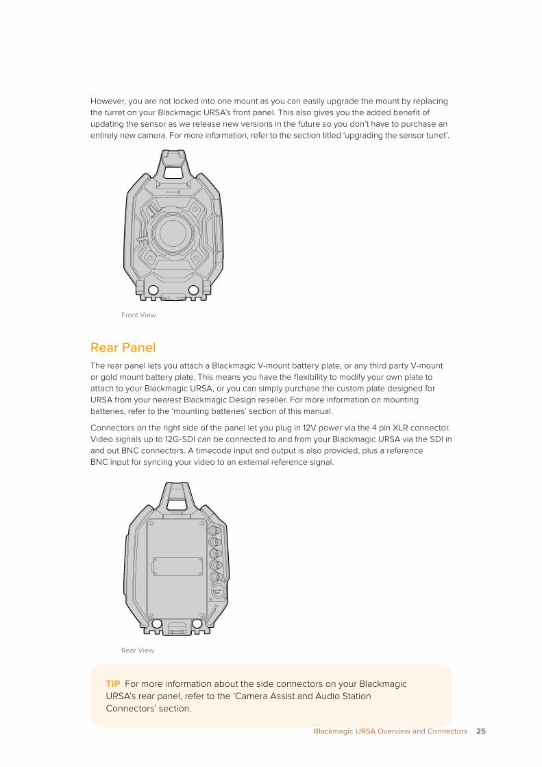
However, you are not locked into one mount as you can easily upgrade the mount by replacing the turret on your Blackmagic URSA’s front panel. This also gives you the added benefit of updating the sensor as we release new versions in the future so you don’t have to purchase an entirely new camera. For more information, refer to the section titled ‘upgrading the sensor turret’.
Front View
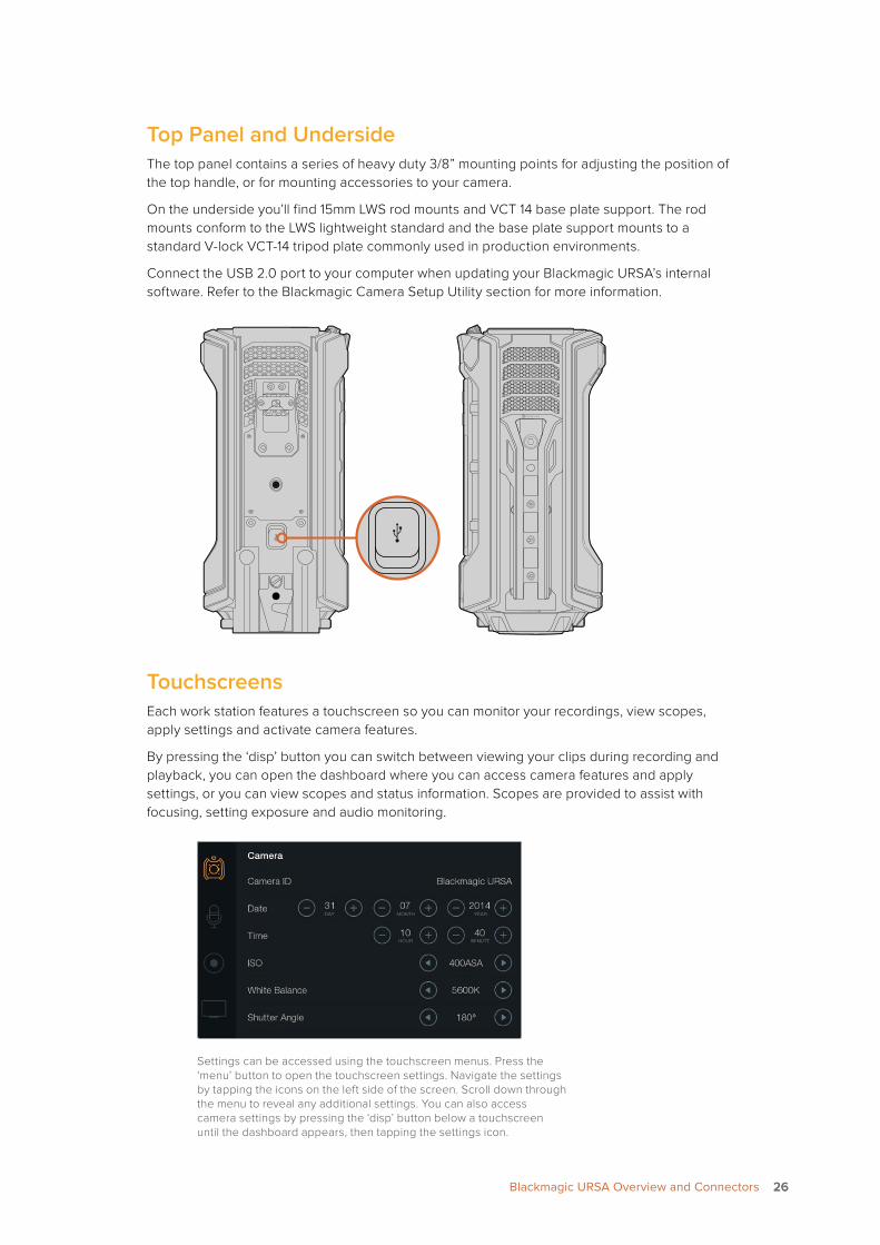
Rear PanelThe rear panel lets you attach a Blackmagic V-mount battery plate, or any third party V-mount or gold mount battery plate. This means you have the flexibility to modify your own plate to attach to your Blackmagic URSA, or you can simply purchase the custom plate designed for URSA from your nearest Blackmagic Design reseller. For more information on mounting batteries, refer to the ‘mounting batteries’ section of this manual.
Connectors on the right side of the panel let you plug in 12V power via the 4 pin XLR connector. Video signals up to 12G-SDI can be connected to and from your Blackmagic URSA via the SDI in and out BNC connectors. A timecode input and output is also provided, plus a reference BNC input for syncing your video to an external reference signal.
Rear View
REC
ZOOM
DISP
PGM
1
CFAST
IRIS
FOCUS
REC
IRIS
FOCUS PEAK DISP MENU SLATE
2
IRIS
SDI OUT
L R
SDI IN
REF IN
TIMECODE IN
TIMECODE OUT
12V
CH1SOLO
CH1MUTE
CH2MUTE
CH2SOLO
FOCUS PEAK DISP MENU SLATE
PU
SHP
USH
PU
SH
0
-6
-12
-18
-24
-30
-36
-42
-48
REC
ZOOM
DISP
PGM
1
CFAST
IRIS
FOCUS
REC
IRIS
FOCUS PEAK DISP MENU SLATE
2
IRIS
SDI OUT
L R
SDI IN
REF IN
TIMECODE IN
TIMECODE OUT
12V
CH1SOLO
CH1MUTE
CH2MUTE
CH2SOLO
FOCUS PEAK DISP MENU SLATE
PU
SHP
USH
PU
SH
0
-6
-12
-18
-24
-30
-36
-42
-48
TIP For more information about the side connectors on your Blackmagic URSA’s rear panel, refer to the ‘Camera Assist and Audio Station Connectors’ section.
2525Blackmagic URSA Overview and Connectors
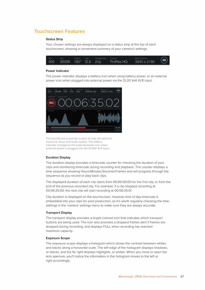
Top Panel and UndersideThe top panel contains a series of heavy duty 3/8” mounting points for adjusting the position of the top handle, or for mounting accessories to your camera.
On the underside you’ll find 15mm LWS rod mounts and VCT 14 base plate support. The rod mounts conform to the LWS lightweight standard and the base plate support mounts to a standard V-lock VCT-14 tripod plate commonly used in production environments.
Connect the USB 2.0 port to your computer when updating your Blackmagic URSA’s internal software. Refer to the Blackmagic Camera Setup Utility section for more information.
TouchscreensEach work station features a touchscreen so you can monitor your recordings, view scopes, apply settings and activate camera features.
By pressing the ‘disp’ button you can switch between viewing your clips during recording and playback, you can open the dashboard where you can access camera features and apply settings, or you can view scopes and status information. Scopes are provided to assist with focusing, setting exposure and audio monitoring.
Settings can be accessed using the touchscreen menus. Press the ‘menu’ button to open the touchscreen settings. Navigate the settings by tapping the icons on the left side of the screen. Scroll down through the menu to reveal any additional settings. You can also access camera settings by pressing the ‘disp’ button below a touchscreen until the dashboard appears, then tapping the settings icon.
REC
ZOOM
DISP
PGM
1
CFAST
IRIS
FOCUS
REC
IRIS
FOCUS PEAK DISP MENU SLATE
2
IRIS
SDI OUT
0
-6
-12
-18
-24
-30
-36
-42
-48
L R
SDI IN
REF IN
TIMECODE IN
TIMECODE OUT
12V
CH1SOLO
CH1MUTE
CH2MUTE
CH2SOLO
FOCUS PEAK DISP MENU SLATE
PU
SHP
USH
PU
SH
REC
ZOOM
DISP
PGM
1
CFAST
IRIS
FOCUS
REC
IRIS
FOCUS PEAK DISP MENU SLATE
2
IRIS
SDI OUT
0
-6
-12
-18
-24
-30
-36
-42
-48
L R
SDI IN
REF IN
TIMECODE IN
TIMECODE OUT
12V
CH1SOLO
CH1MUTE
CH2MUTE
CH2SOLO
FOCUS PEAK DISP MENU SLATE
PU
SHP
USH
PU
SH
REC
ZOOM
DISP
PGM
1
CFAST
IRIS
FOCUS
REC
IRIS
FOCUSPEAKDISPMENUSLATE
2
IRIS
SDI OUT
0
-6
-12
-18
-24
-30
-36
-42
-48
LR
SDI IN
REF IN
TIMECODE IN
TIMECODE OUT
12V
CH1SOLO
CH1MUTE
CH2MUTE
CH2SOLO
FOCUSPEAKDISPMENUSLATE
PU
SHP
USH
PU
SH
2626Blackmagic URSA Overview and Connectors
Touchscreen FeaturesStatus Strip
Your chosen settings are always displayed on a status strip at the top of each touchscreen, showing a convenient summary of your camera’s settings.
Power Indicator
The power indicator displays a battery icon when using battery power, or an external power icon when plugged into external power via the 12-20 Volt XLR input.
The touchscreens provide scopes to help set optimum exposure, focus and audio quality. The battery indicator changes to the external power icon when external power is plugged into the 12-20V XLR input.
Duration Display
The duration display provides a timecode counter for checking the duration of your clips and monitoring timecode during recording and playback. The counter displays a time sequence showing Hours:Minutes:Seconds:Frames and will progress through the sequence as you record or play back clips.
The displayed duration of each clip starts from 00:00:00:00 for the first clip, or from the end of the previous recorded clip. For example, if a clip stopped recording at 00:06:25:00, the next clip will start recording at 00:06:25:01.
Clip duration is displayed on the touchscreen, however time of day timecode is embedded into your clips for post production, so it’s worth regularly checking the time settings in the ‘camera’ settings menu to make sure they are always accurate.
Transport Display
The transport display provides a bright colored icon that indicates which transport buttons are being used. The icon also provides a dropped frames alert if frames are dropped during recording, and displays FULL when recording has reached maximum capacity.
Exposure Scope
The exposure scope displays a histogram which shows the contrast between whites and blacks along a horizontal scale. The left edge of the histogram displays shadows, or blacks, and the far right displays highlights, or whites. When you close or open the lens aperture, you’ll notice the information in the histogram moves to the left or right accordingly.
2727Blackmagic URSA Overview and Connectors
To achieve optimum exposure, set your lens aperture so the information is distributed towards the right of the histogram and curves to a point at the bottom right edge. This is known as ETTR, or exposing to the right.
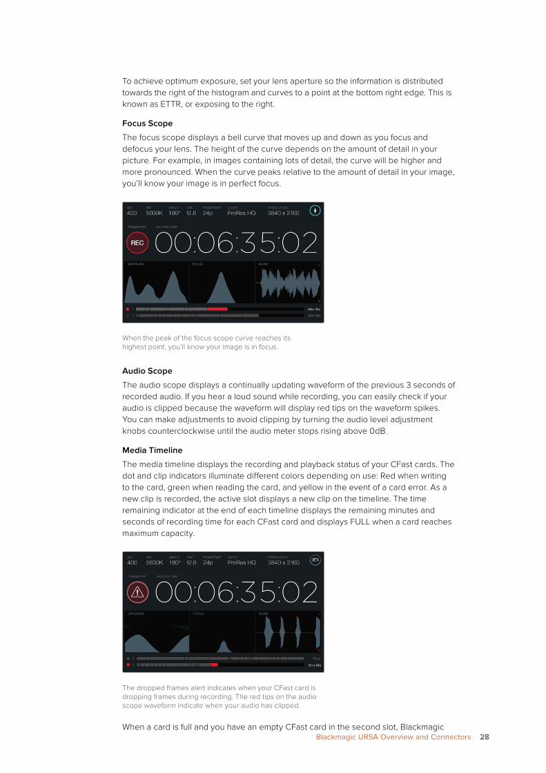
Focus Scope
The focus scope displays a bell curve that moves up and down as you focus and defocus your lens. The height of the curve depends on the amount of detail in your picture. For example, in images containing lots of detail, the curve will be higher and more pronounced. When the curve peaks relative to the amount of detail in your image, you’ll know your image is in perfect focus.
When the peak of the focus scope curve reaches its highest point, you’ll know your image is in focus.
Audio Scope
The audio scope displays a continually updating waveform of the previous 3 seconds of recorded audio. If you hear a loud sound while recording, you can easily check if your audio is clipped because the waveform will display red tips on the waveform spikes. You can make adjustments to avoid clipping by turning the audio level adjustment knobs counterclockwise until the audio meter stops rising above 0dB.
Media Timeline
The media timeline displays the recording and playback status of your CFast cards. The dot and clip indicators illuminate different colors depending on use: Red when writing to the card, green when reading the card, and yellow in the event of a card error. As a new clip is recorded, the active slot displays a new clip on the timeline. The time remaining indicator at the end of each timeline displays the remaining minutes and seconds of recording time for each CFast card and displays FULL when a card reaches maximum capacity.
The dropped frames alert indicates when your CFast card is dropping frames during recording. The red tips on the audio scope waveform indicate when your audio has clipped.
When a card is full and you have an empty CFast card in the second slot, Blackmagic 2828Blackmagic URSA Overview and Connectors
URSA will automatically record to the other CFast card. To play a selected clip, press the ‘play’ button on the fold out monitor transport controls, or on the outside of the door.
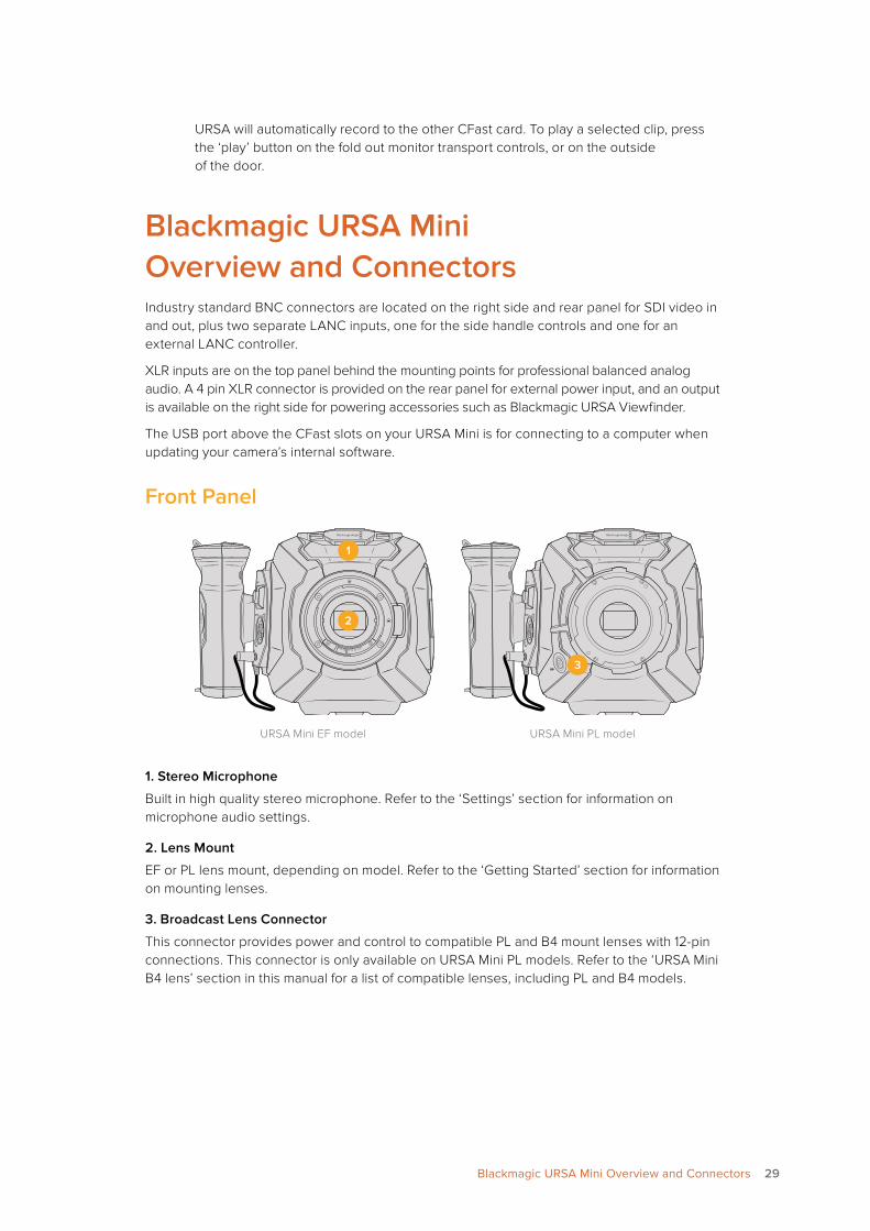
Blackmagic URSA Mini Overview and ConnectorsIndustry standard BNC connectors are located on the right side and rear panel for SDI video in and out, plus two separate LANC inputs, one for the side handle controls and one for an external LANC controller.
XLR inputs are on the top panel behind the mounting points for professional balanced analog audio. A 4 pin XLR connector is provided on the rear panel for external power input, and an output is available on the right side for powering accessories such as Blackmagic URSA Viewfinder.
The USB port above the CFast slots on your URSA Mini is for connecting to a computer when updating your camera’s internal software.
Front Panel
1
2
3
URSA Mini EF model URSA Mini PL model
1. Stereo Microphone
Built in high quality stereo microphone. Refer to the ‘Settings’ section for information on microphone audio settings.
2. Lens Mount
EF or PL lens mount, depending on model. Refer to the ‘Getting Started’ section for information on mounting lenses.
3. Broadcast Lens Connector
This connector provides power and control to compatible PL and B4 mount lenses with 12-pin connections. This connector is only available on URSA Mini PL models. Refer to the ‘URSA Mini B4 lens’ section in this manual for a list of compatible lenses, including PL and B4 models.
29Blackmagic URSA Mini Overview and Connectors
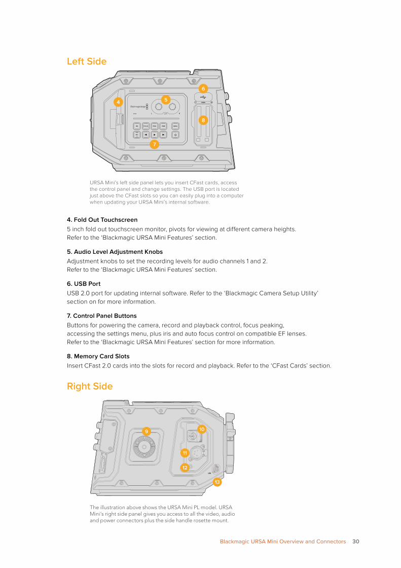
Left Side
URSA Mini’s left side panel lets you insert CFast cards, access the control panel and change settings. The USB port is located just above the CFast slots so you can easily plug into a computer when updating your URSA Mini’s internal software.
4. Fold Out Touchscreen5 inch fold out touchscreen monitor, pivots for viewing at different camera heights. Refer to the ‘Blackmagic URSA Mini Features’ section.
5. Audio Level Adjustment KnobsAdjustment knobs to set the recording levels for audio channels 1 and 2. Refer to the ‘Blackmagic URSA Mini Features’ section.
6. USB PortUSB 2.0 port for updating internal software. Refer to the ‘Blackmagic Camera Setup Utility’ section on for more information.
7. Control Panel ButtonsButtons for powering the camera, record and playback control, focus peaking, accessing the settings menu, plus iris and auto focus control on compatible EF lenses. Refer to the ‘Blackmagic URSA Mini Features’ section for more information.
8. Memory Card SlotsInsert CFast 2.0 cards into the slots for record and playback. Refer to the ‘CFast Cards’ section.
Right Side
The illustration above shows the URSA Mini PL model. URSA Mini’s right side panel gives you access to all the video, audio and power connectors plus the side handle rosette mount.
1 2CFAST4 5
6
7
8
9 10
11
12
13
30Blackmagic URSA Mini Overview and Connectors
9. Side Rosette Mount
Standard rosette mount for the side handle. Refer to the ‘Getting Started’ and ‘Blackmagic URSA Mini Shoulder Mount Kit’ sections.
10. HD Monitoring Output
3G-SDI connector for down converted 1080HD output. Use with Blackmagic URSA Viewfinder or external monitors. Refer to the ‘Camera Video Output’ and ‘Blackmagic URSA Viewfinder’ sections for more information.
11. +12V Power Output
4 pin XLR connector for powering Blackmagic URSA Viewfinder, or external monitors and accessories. Refer to the ‘Blackmagic URSA Viewfinder’ section for more information.
12. LANC Input
Dedicated 2.5mm TRS LANC connector for Blackmagic URSA Mini side handle. Refer to the ‘Getting Started’ section on page 6 for more information on connecting the side handle.
13. Broadcast Lens Control Connector
Provides power and control to compatible PL and B4 mount lenses with 12-pin connections. This connection is only available on URSA Mini PL models. Refer to the ‘URSA Mini B4 lens’ section in this manual for a list of compatible lenses, including PL and B4 models.
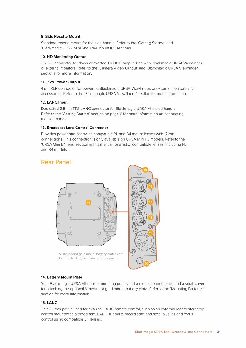
Rear Panel
14. Battery Mount Plate
Your Blackmagic URSA Mini has 4 mounting points and a molex connector behind a small cover for attaching the optional V-mount or gold mount battery plate. Refer to the ‘Mounting Batteries’ section for more information.
15. LANC
This 2.5mm jack is used for external LANC remote control, such as an external record start stop control mounted to a tripod arm. LANC supports record start and stop, plus iris and focus control using compatible EF lenses.
14
15
16
17
18
19
20
V-mount and gold mount battery plates can be attached to your camera’s rear panel.
31Blackmagic URSA Mini Overview and Connectors
16. 12G-SDI In
The 12G-SDI input is used for connecting to a switcher or external recorder such as Blackmagic Video Assist. This lets you monitor the program output from a switcher, or view the playback of your external recording on your Blackmagic URSA Mini’s built in LCD and via the HD monitoring output. When working with multiple cameras this is an easy way to check angles prior to shooting.
You can also use ATEM Switchers ‘camera control’ feature to remotely adjust many URSA Mini functions. See the section ‘controlling URSA Mini with ATEM camera control’ for more information.
17. 12G SDI Out
Blackmagic URSA Mini’s 12G-SDI output is used to send HD and Ultra HD video to SDI equipment such as routers, monitors, SDI capture devices, and broadcast switchers.
18. Reference and Timecode In
This input automatically recognizes and switches between timecode and reference input signals. Synchronize Blackmagic URSA Mini to a common reference signal, such as tri-level sync, by connecting to the ‘reference’ BNC input marked ‘REF In’. This lets you sync URSA Mini to other SDI video equipment, for example, when using multiple cameras connected to a switcher. You can also use this connector to record timecode from other professional audio and video equipment, such as audio mixers and clapper boards. This ensures audio and picture, or video from multiple cameras, can be easily synchronized during post production.
19. 12V+ Power Input
Use the 4 pin 12-20 Volt XLR connector to plug in power from external sources, such as the supplied power adapter, power outlets, portable batteries and generators.
20. Headphone/Headset
The 3.5mm jack output is used for headphone monitoring and talkback. You can plug in iPhone and Android compatible headsets that have a built in microphone for quick and easy talkback. Talkback audio is embedded in channels 15 and 16 of the SDI output.
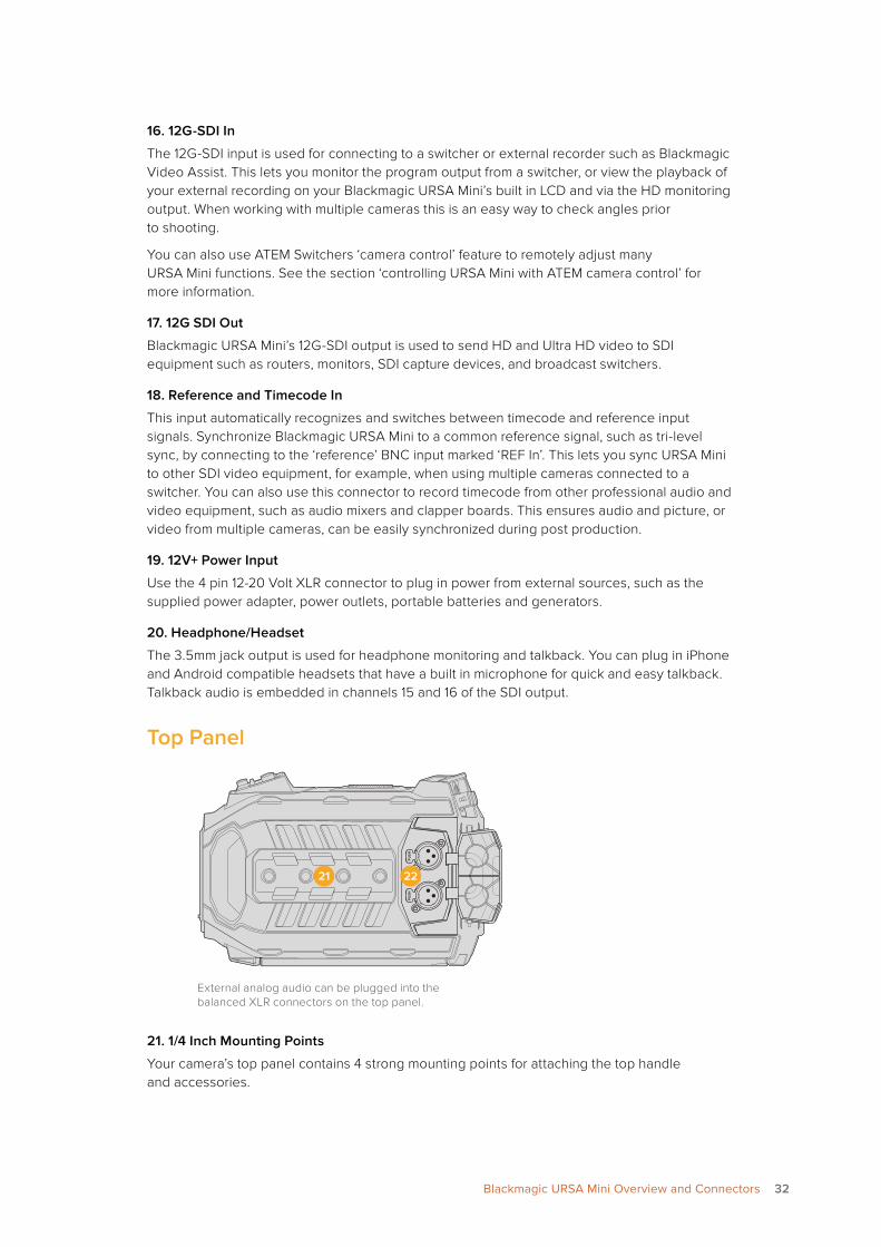
Top Panel
External analog audio can be plugged into the balanced XLR connectors on the top panel.
21. 1/4 Inch Mounting Points
Your camera’s top panel contains 4 strong mounting points for attaching the top handle and accessories.
PU
SHP
USH
2221
32Blackmagic URSA Mini Overview and Connectors
22. XLR Audio In
Use the balanced XLR inputs to plug in external analog audio from professional equipment such as audio mixers, PA systems or external microphones. The XLR connectors supply 48V phantom power so you can use microphones that aren’t self powered. To enable phantom power select ‘inputs’ on the ‘audio input’ setting, plus ‘mic low’ or ‘mic high’ on the audio ‘input levels’ settings. Scroll the menu to reveal the ‘phantom power’ setting and select ‘on’. To disable phantom power, select ‘off’. Phantom power is active only when external audio inputs are selected in the audio settings.
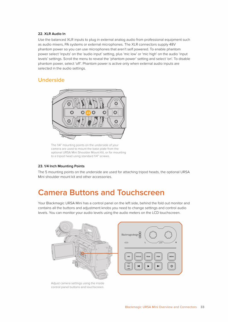
Underside
The 1/4” mounting points on the underside of your camera are used to mount the base plate from the optional URSA Mini Shoulder Mount Kit, or for mounting to a tripod head using standard 1/4” screws.
23. 1/4 Inch Mounting Points
The 5 mounting points on the underside are used for attaching tripod heads, the optional URSA Mini shoulder mount kit and other accessories.
Camera Buttons and TouchscreenYour Blackmagic URSA Mini has a control panel on the left side, behind the fold out monitor and contains all the buttons and adjustment knobs you need to change settings and control audio levels. You can monitor your audio levels using the audio meters on the LCD touchscreen.
Adjust camera settings using the inside control panel buttons and touchscreen.
Blac
kmag
ic UR
SA M
ini
23
IRIS
REC
FOCUSPEAK
DISP
MENU
1 2CFAST
33Blackmagic URSA Mini Overview and Connectors
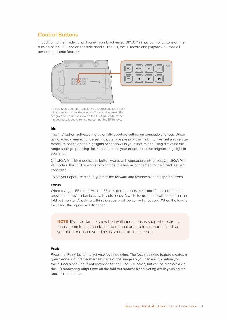
Control ButtonsIn addition to the inside control panel, your Blackmagic URSA Mini has control buttons on the outside of the LCD and on the side handle. The iris, focus, record and playback buttons all perform the same function.
The outside panel buttons let you record and play back clips, turn focus peaking on or off, switch between the program and camera view on the LCD, plus adjust the iris and auto focus when using compatible EF lenses.
Iris
The ‘Iris’ button activates the automatic aperture setting on compatible lenses. When using video dynamic range settings, a single press of the iris button will set an average exposure based on the highlights or shadows in your shot. When using film dynamic range settings, pressing the iris button sets your exposure to the brightest highlight in your shot.
On URSA Mini EF models, this button works with compatible EF lenses. On URSA Mini PL models, this button works with compatible lenses connected to the broadcast lens controller.
To set your aperture manually, press the forward and reverse skip transport buttons.
Focus
When using an EF mount with an EF lens that supports electronic focus adjustments, press the ‘focus’ button to activate auto focus. A white focus square will appear on the fold out monitor. Anything within the square will be correctly focused. When the lens is focussed, the square will disappear.
Peak
Press the ‘Peak’ button to activate focus peaking. The focus peaking feature creates a green edge around the sharpest parts of the image so you can easily confirm your focus. Focus peaking is not recorded to the CFast 2.0 cards, but can be displayed via the HD monitoring output and on the fold out monitor by activating overlays using the touchscreen menu.
F1 F2
F1 F2
NOTE It’s important to know that while most lenses support electronic focus, some lenses can be set to manual or auto focus modes, and so you need to ensure your lens is set to auto focus mode.
34Blackmagic URSA Mini Overview and Connectors
Program
The program button is marked PGM and lets you switch the LCD between the camera view and any signal plugged into the 12G-SDI input on the rear panel. This means if you’re using URSA Mini in a live broadcast, you can plug in the switcher’s program output and monitor it during the shoot. Simply press the program button to switch between views.
Menu
Press the ‘menu’ button to open the dashboard. Press and hold the ‘menu’ button to bypass the dashboard and go straight to the settings menu. Refer to the ‘settings’ section for more information about the dashboard feature and how to adjust settings.
Record
The ‘record’ button is marked REC on your Blackmagic URSA Mini’s control panel, fold out LCD and side handle. Press any of the record buttons to start and stop recording. Refer to the ‘recording’ section for more information.
Playback Control Buttons
The playback buttons let you start and stop playback, plus skip to the next or previous clip. On Blackmagic URSA Mini EF, the forward and reverse skip buttons can also be used to open or close the iris when using compatible lenses. Refer to the ‘playback’ section for more information on how to use the playback buttons.
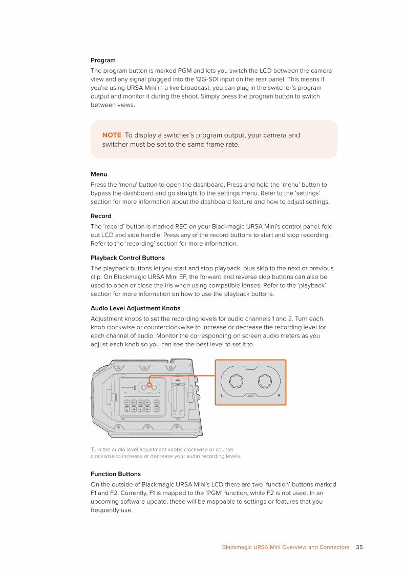
Audio Level Adjustment Knobs
Adjustment knobs to set the recording levels for audio channels 1 and 2. Turn each knob clockwise or counterclockwise to increase or decrease the recording level for each channel of audio. Monitor the corresponding on screen audio meters as you adjust each knob so you can see the best level to set it to.
Turn the audio level adjustment knobs clockwise or counter clockwise to increase or decrease your audio recording levels.
Function Buttons
On the outside of Blackmagic URSA Mini’s LCD there are two ‘function’ buttons marked F1 and F2. Currently, F1 is mapped to the ‘PGM’ function, while F2 is not used. In an upcoming software update, these will be mappable to settings or features that you frequently use.
NOTE To display a switcher’s program output, your camera and switcher must be set to the same frame rate.
1 2CFAST
1 2CFAST
35Blackmagic URSA Mini Overview and Connectors
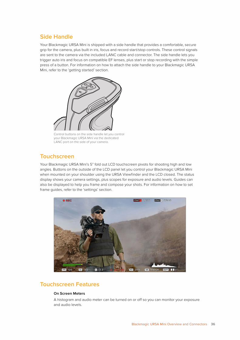
Side HandleYour Blackmagic URSA Mini is shipped with a side handle that provides a comfortable, secure grip for the camera, plus built in iris, focus and record start/stop controls. These control signals are sent to the camera via the included LANC cable and connector. The side handle lets you trigger auto iris and focus on compatible EF lenses, plus start or stop recording with the simple press of a button. For information on how to attach the side handle to your Blackmagic URSA Mini, refer to the ‘getting started’ section.
Control buttons on the side handle let you control your Blackmagic URSA Mini via the dedicated LANC port on the side of your camera.
TouchscreenYour Blackmagic URSA Mini’s 5” fold out LCD touchscreen pivots for shooting high and low angles. Buttons on the outside of the LCD panel let you control your Blackmagic URSA Mini when mounted on your shoulder using the URSA Viewfinder and the LCD closed. The status display shows your camera settings, plus scopes for exposure and audio levels. Guides can also be displayed to help you frame and compose your shots. For information on how to set frame guides, refer to the ‘settings’ section.
Touchscreen FeaturesOn Screen Meters
A histogram and audio meter can be turned on or off so you can monitor your exposure and audio levels.
36Blackmagic URSA Mini Overview and Connectors
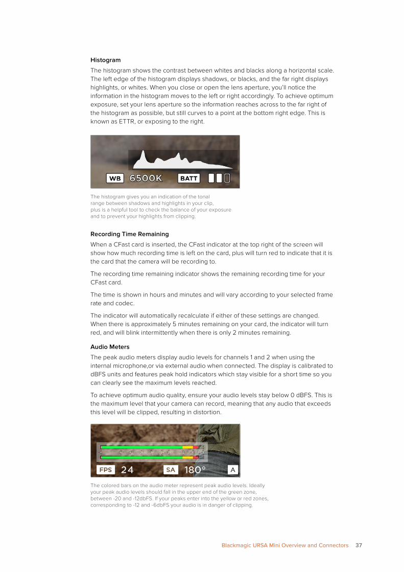
Histogram
The histogram shows the contrast between whites and blacks along a horizontal scale. The left edge of the histogram displays shadows, or blacks, and the far right displays highlights, or whites. When you close or open the lens aperture, you’ll notice the information in the histogram moves to the left or right accordingly. To achieve optimum exposure, set your lens aperture so the information reaches across to the far right of the histogram as possible, but still curves to a point at the bottom right edge. This is known as ETTR, or exposing to the right.
The histogram gives you an indication of the tonal range between shadows and highlights in your clip, plus is a helpful tool to check the balance of your exposure and to prevent your highlights from clipping.
Recording Time Remaining
When a CFast card is inserted, the CFast indicator at the top right of the screen will show how much recording time is left on the card, plus will turn red to indicate that it is the card that the camera will be recording to.
The recording time remaining indicator shows the remaining recording time for your CFast card.
The time is shown in hours and minutes and will vary according to your selected frame rate and codec.
The indicator will automatically recalculate if either of these settings are changed. When there is approximately 5 minutes remaining on your card, the indicator will turn red, and will blink intermittently when there is only 2 minutes remaining.
Audio Meters
The peak audio meters display audio levels for channels 1 and 2 when using the internal microphone,or via external audio when connected. The display is calibrated to dBFS units and features peak hold indicators which stay visible for a short time so you can clearly see the maximum levels reached.
To achieve optimum audio quality, ensure your audio levels stay below 0 dBFS. This is the maximum level that your camera can record, meaning that any audio that exceeds this level will be clipped, resulting in distortion.
The colored bars on the audio meter represent peak audio levels. Ideally your peak audio levels should fall in the upper end of the green zone, between -20 and -12dbFS. If your peaks enter into the yellow or red zones, corresponding to -12 and -6dbFS your audio is in danger of clipping.
37Blackmagic URSA Mini Overview and Connectors
Settings
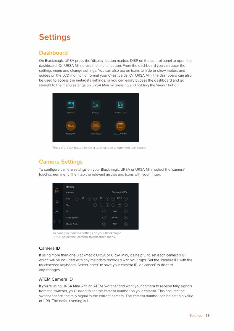
DashboardOn Blackmagic URSA press the ‘display’ button marked DISP on the control panel to open the dashboard. On URSA Mini press the ‘menu’ button. From the dashboard you can open the settings menu and change settings. You can also tap on icons to hide or show meters and guides on the LCD monitor, or format your CFast cards. On URSA Mini the dashboard can also be used to access the metadata settings, or you can easily bypass the dashboard and go straight to the menu settings on URSA Mini by pressing and holding the ‘menu’ button.
Press the ‘disp’ button below a touchscreen to open the dashboard.
Camera SettingsTo configure camera settings on your Blackmagic URSA or URSA Mini, select the ‘camera’ touchscreen menu, then tap the relevant arrows and icons with your finger.
To configure camera settings on your Blackmagic URSA, select the ‘camera’ touchscreen menu.
Camera IDIf using more than one Blackmagic URSA or URSA Mini, it’s helpful to set each camera’s ID which will be included with any metadata recorded with your clips. Set the ‘camera ID’ with the touchscreen keyboard. Select ‘enter’ to save your camera ID, or ‘cancel’ to discard any changes.
ATEM Camera IDIf you’re using URSA Mini with an ATEM Switcher and want your camera to receive tally signals from the switcher, you’ll need to set the camera number on your camera. This ensures the switcher sends the tally signal to the correct camera. The camera number can be set to a value of 1-99. The default setting is 1.
38Settings
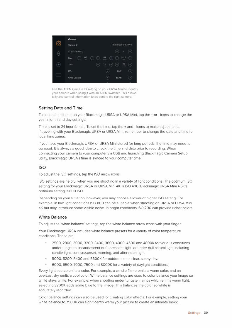
Use the ATEM Camera ID setting on your URSA Mini to identify your camera when using it with an ATEM switcher. This allows tally and control information to be sent to the right camera.
Setting Date and TimeTo set date and time on your Blackmagic URSA or URSA Mini, tap the + or - icons to change the year, month and day settings.
Time is set to 24 hour format. To set the time, tap the + and - icons to make adjustments. If traveling with your Blackmagic URSA or URSA Mini, remember to change the date and time to local time zones.
If you have your Blackmagic URSA or URSA Mini stored for long periods, the time may need to be reset. It is always a good idea to check the time and date prior to recording. When connecting your camera to your computer via USB and launching Blackmagic Camera Setup utility, Blackmagic URSA’s time is synced to your computer time.
ISOTo adjust the ISO settings, tap the ISO arrow icons.
ISO settings are helpful when you are shooting in a variety of light conditions. The optimum ISO setting for your Blackmagic URSA or URSA Mini 4K is ISO 400. Blackmagic URSA Mini 4.6K’s optimum setting is 800 ISO.
Depending on your situation, however, you may choose a lower or higher ISO setting. For example, in low light conditions ISO 800 can be suitable when shooting on URSA or URSA Mini 4K but may introduce some visible noise. In bright conditions ISO 200 can provide richer colors.
White BalanceTo adjust the ‘white balance’ settings, tap the white balance arrow icons with your finger.
Your Blackmagic URSA includes white balance presets for a variety of color temperature conditions. These are:
� 2500, 2800, 3000, 3200, 3400, 3600, 4000, 4500 and 4800K for various conditions under tungsten, incandescent or fluorescent light, or under dull natural light including candle light, sunrise/sunset, morning, and after noon light.
� 5000, 5200, 5400 and 5600K for outdoors on a clear, sunny day.
� 6000, 6500, 7000, 7500 and 8000K for a variety of daylight conditions.
Every light source emits a color. For example, a candle flame emits a warm color, and an overcast sky emits a cool color. White balance settings are used to color balance your image so white stays white. For example, when shooting under tungsten lamps which emit a warm light, selecting 3200K adds some blue to the image. This balances the color so white is accurately recorded.
Color balance settings can also be used for creating color effects. For example, setting your white balance to 7500K can significantly warm your picture to create an intimate mood.
39Settings

The camera settings screen.
Shutter AngleTo adjust the ‘shutter angle’ settings, tap the shutter angle arrow icons.
Shutter angle defines the level of motion blur in your video, and can be used to compensate for varying light conditions. 180 degrees is the optimum shutter angle for capturing a satisfying motion blur in most conditions. However as lighting conditions change, or the amount of movement in your scene increases, you may decide to adjust accordingly.
For example, 360 degrees is considered ‘wide open’ and allows maximum light onto the sensor. This is useful for low light conditions with subtle movement in your scene. Alternatively, if shooting motor sport with rapid movement, a narrow shutter angle will provide minimal motion blur for sharper, crisper images.
When shooting 24p in countries with 50 hertz power supplies, 172.8 degrees will minimize potential flickering from 50Hz light sources.
DetailUse this setting to sharpen your URSA Mini’s image. Decrease or increase the level of sharpening by selecting ‘off’, ‘low’, ‘medium’ or ‘high’.
When sharpening is set to ‘low’, ‘medium’ or ‘high’, sharpening will be applied to ProRes video recorded on camera as well as your URSA Mini’s SDI output.
This setting is intended for live studio where there is no time for post production and you want to output the image live to air. We recommend leaving it ‘off’ for images you are recording for further post production. For this reason, sharpening is not applied to RAW files that are intended for significant post processing.
Auto ExposureBlackmagic URSA Mini gives you several auto exposure options. These are useful for situations where a fixed exposure is not always practical, such as electronic news gathering and shooting documentary footage, or unpredictable action in a studio environment.
The available auto exposure settings are:
Iris
This setting automatically adjusts iris aperture to maintain a constant exposure, while keeping shutter speed constant. This will keep motion blur constant, but may affect your depth of field. However, in well lit environments where you can keep your aperture at approximately f8 to f11, any changes probably won’t be noticeable.
Shutter
This setting automatically adjusts shutter speed to maintain a constant exposure while keeping iris aperture constant. If you want to maintain a fixed depth of field, this is the setting to choose. It’s worth mentioning that the subtle automatic adjustments of the
40Settings
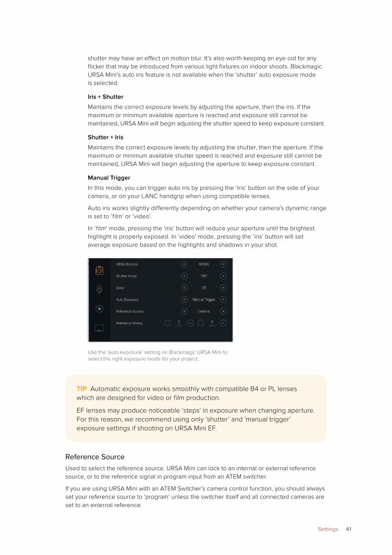
shutter may have an effect on motion blur. It’s also worth keeping an eye out for any flicker that may be introduced from various light fixtures on indoor shoots. Blackmagic URSA Mini’s auto iris feature is not available when the ‘shutter’ auto exposure mode is selected.
Iris + Shutter
Mantains the correct exposure levels by adjusting the aperture, then the iris. If the maximum or minimum available aperture is reached and exposure still cannot be maintained, URSA Mini will begin adjusting the shutter speed to keep exposure constant.
Shutter + Iris
Maintains the correct exposure levels by adjusting the shutter, then the aperture. If the maximum or minimum available shutter speed is reached and exposure still cannot be maintained, URSA Mini will begin adjusting the aperture to keep exposure constant.
Manual Trigger
In this mode, you can trigger auto iris by pressing the ‘Iris’ button on the side of your camera, or on your LANC handgrip when using compatible lenses.
Auto iris works slightly differently depending on whether your camera’s dynamic range is set to ‘film’ or ‘video’.
In ‘film’ mode, pressing the ‘iris’ button will reduce your aperture until the brightest highlight is properly exposed. In ‘video’ mode, pressing the ‘iris’ button will set average exposure based on the highlights and shadows in your shot.
Use the ‘auto exposure’ setting on Blackmagic URSA Mini to select the right exposure mode for your project.
Reference SourceUsed to select the reference source. URSA Mini can lock to an internal or external reference source, or to the reference signal in program input from an ATEM switcher.
If you are using URSA Mini with an ATEM Switcher’s camera control function, you should always set your reference source to ‘program’ unless the switcher itself and all connected cameras are set to an external reference.
TIP Automatic exposure works smoothly with compatible B4 or PL lenses which are designed for video or film production.
EF lenses may produce noticeable ‘steps’ in exposure when changing aperture. For this reason, we recommend using only ‘shutter’ and ‘manual trigger’ exposure settings if shooting on URSA Mini EF.
41Settings
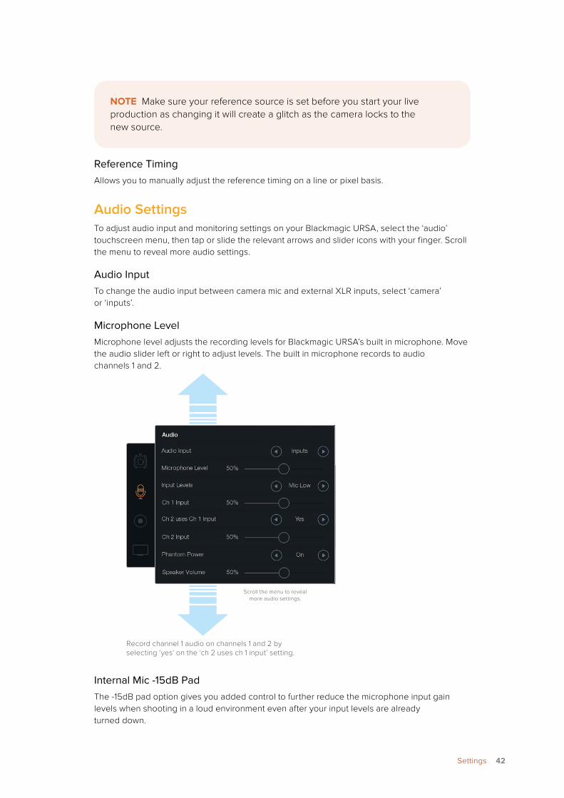
Reference TimingAllows you to manually adjust the reference timing on a line or pixel basis.
Audio SettingsTo adjust audio input and monitoring settings on your Blackmagic URSA, select the ‘audio’ touchscreen menu, then tap or slide the relevant arrows and slider icons with your finger. Scroll the menu to reveal more audio settings.
Audio InputTo change the audio input between camera mic and external XLR inputs, select ‘camera’ or ‘inputs’.
Microphone LevelMicrophone level adjusts the recording levels for Blackmagic URSA’s built in microphone. Move the audio slider left or right to adjust levels. The built in microphone records to audio channels 1 and 2.
Record channel 1 audio on channels 1 and 2 by selecting ‘yes’ on the ‘ch 2 uses ch 1 input’ setting.
Internal Mic -15dB PadThe -15dB pad option gives you added control to further reduce the microphone input gain levels when shooting in a loud environment even after your input levels are already turned down.
NOTE Make sure your reference source is set before you start your live production as changing it will create a glitch as the camera locks to the new source.
Scroll the menu to reveal more audio settings.
42Settings
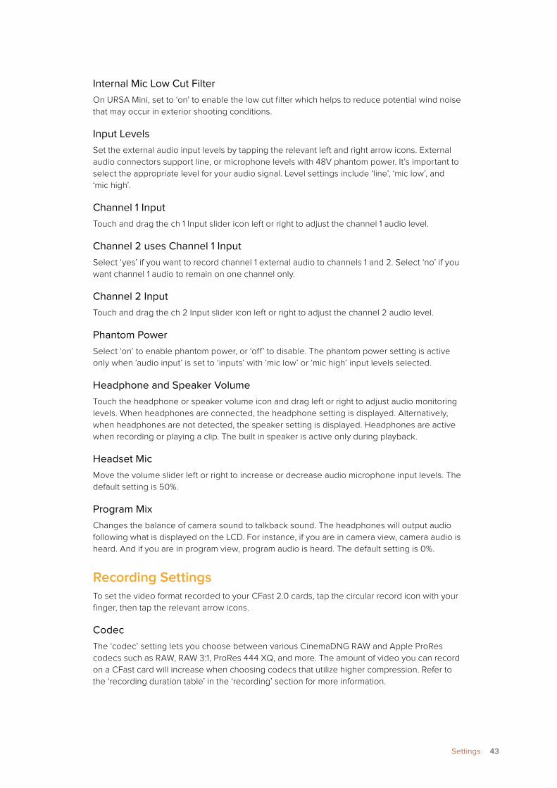
Internal Mic Low Cut FilterOn URSA Mini, set to ‘on’ to enable the low cut filter which helps to reduce potential wind noise that may occur in exterior shooting conditions.
Input LevelsSet the external audio input levels by tapping the relevant left and right arrow icons. External audio connectors support line, or microphone levels with 48V phantom power. It’s important to select the appropriate level for your audio signal. Level settings include ‘line’, ‘mic low’, and ‘mic high’.
Channel 1 InputTouch and drag the ch 1 Input slider icon left or right to adjust the channel 1 audio level.
Channel 2 uses Channel 1 InputSelect ‘yes’ if you want to record channel 1 external audio to channels 1 and 2. Select ‘no’ if you want channel 1 audio to remain on one channel only.
Channel 2 InputTouch and drag the ch 2 Input slider icon left or right to adjust the channel 2 audio level.
Phantom PowerSelect ‘on’ to enable phantom power, or ‘off’ to disable. The phantom power setting is active only when ‘audio input’ is set to ‘inputs’ with ‘mic low’ or ‘mic high’ input levels selected.
Headphone and Speaker VolumeTouch the headphone or speaker volume icon and drag left or right to adjust audio monitoring levels. When headphones are connected, the headphone setting is displayed. Alternatively, when headphones are not detected, the speaker setting is displayed. Headphones are active when recording or playing a clip. The built in speaker is active only during playback.
Headset MicMove the volume slider left or right to increase or decrease audio microphone input levels. The default setting is 50%.
Program MixChanges the balance of camera sound to talkback sound. The headphones will output audio following what is displayed on the LCD. For instance, if you are in camera view, camera audio is heard. And if you are in program view, program audio is heard. The default setting is 0%.
Recording SettingsTo set the video format recorded to your CFast 2.0 cards, tap the circular record icon with your finger, then tap the relevant arrow icons.
CodecThe ‘codec’ setting lets you choose between various CinemaDNG RAW and Apple ProRes codecs such as RAW, RAW 3:1, ProRes 444 XQ, and more. The amount of video you can record on a CFast card will increase when choosing codecs that utilize higher compression. Refer to the ‘recording duration table’ in the ‘recording’ section for more information.
43Settings
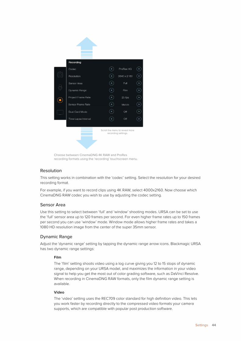
Choose between CinemaDNG 4K RAW and ProRes recording formats using the ‘recording’ touchscreen menu.
ResolutionThis setting works in combination with the ‘codec’ setting. Select the resolution for your desired recording format.
For example, if you want to record clips using 4K RAW, select 4000x2160. Now choose which CinemaDNG RAW codec you wish to use by adjusting the codec setting.
Sensor AreaUse this setting to select between ‘full’ and ‘window’ shooting modes. URSA can be set to use the ‘full’ sensor area up to 120 frames per second. For even higher frame rates up to 150 frames per second you can use ‘window’ mode. Window mode allows higher frame rates and takes a 1080 HD resolution image from the center of the super 35mm sensor.
Dynamic RangeAdjust the ‘dynamic range’ setting by tapping the dynamic range arrow icons. Blackmagic URSA has two dynamic range settings:
Film
The ‘film’ setting shoots video using a log curve giving you 12 to 15 stops of dynamic range, depending on your URSA model, and maximizes the information in your video signal to help you get the most out of color grading software, such as DaVinci Resolve. When recording in CinemaDNG RAW formats, only the film dynamic range setting is available.
Video
The ‘video’ setting uses the REC709 color standard for high definition video. This lets you work faster by recording directly to the compressed video formats your camera supports, which are compatible with popular post production software.
Scroll the menu to reveal more recording settings.
44Settings
Frame RateAdjust the ‘frame rate’ settings by tapping the frame rate arrow icons.
Blackmagic URSA has two frame rate settings; project frame rate and sensor frame rate.
Project Frame Rate
The project frame rate is URSA’s recording format frame rate and provides a selection of common frame rates used in the film and television industry. For example, 23.98 frames per second using 4K ProRes HQ. This frame rate is normally set to match your playback speed used in your post production workflow.
Your Blackmagic URSA has 8 project frame rate settings including 23.98, 24, 25, 29.97, 30, 50, 59.94 and 60 frames per second.
A sensor frame rate higher than your project frame rate will result in slow motion. To ensure your recorded clips play back at standard speed, set the sensor frame rate to match the project frame rate.
Sensor Frame Rate
The sensor frame rate sets how many actual frames from the sensor are recorded every second. This frame rate will affect how fast or slow your video will play back at your set project frame rate. For standard playback speed, make sure you set your sensor frame rate to match your project frame rate by selecting ‘match’ in the sensor frame rate settings.
For information on the maximum frame rates available for each recording format and codec, refer to the ‘maximum sensor frame rates’ table in the ‘recording’ section of this manual.
Variable Frame RatesYou can create dynamic and interesting speed effects in your clips by varying the sensor frame rate. Setting the sensor frame rate higher than your project frame rate will create slow motion during playback. Alternatively, the lower your sensor frame rate, the faster your clips will appear. The principle is similar to overcranking and undercranking a film camera. Overcranking speeds up the sensor frame rate so you can stretch out moments in time during playback to enhance emotion. Undercranking slows down the sensor frame rate so you can increase the action in fast moving scenes. The creative possibilities are endless and entirely up to you!
Dual Card ModeBlackmagic URSA lets you record CinemaDNG RAW clips at higher frame rates by recording to both CFast cards simultaneously. Turn ‘dual card mode’ on or off by tapping the setting arrow icons. You can also enable ‘dual card mode’ to increase the reliability of CFast cards if you find a single card is dropping frames while recording CinemaDNG RAW clips.
45Settings
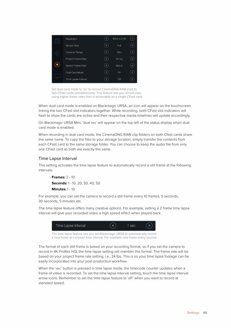
Set dual card mode to ‘on’ to record CinemaDNG RAW clips to two CFast cards simultaneously. This feature lets you record clips using higher frame rates than is achievable on a single CFast card.
When dual card mode is enabled on Blackmagic URSA, an icon will appear on the touchscreen linking the two CFast slot indicators together. While recording, both CFast slot indicators will flash to show the cards are active and their respective media timelines will update accordingly.
On Blackmagic URSA Mini, ‘dual rec’ will appear on the top left of the status display when dual card mode is enabled.
When recording in dual card mode, the CinemaDNG RAW clip folders on both Cfast cards share the same name. To copy the files to your storage location, simply transfer the contents from each CFast card to the same storage folder. You can choose to keep the audio file from only one CFast card as both are exactly the same.
Time Lapse IntervalThis setting activates the time lapse feature to automatically record a still frame at the following intervals:
Frames: 2 - 10
Seconds: 1 - 10, 20, 30, 40, 50
Minutes: 1 - 10
For example, you can set the camera to record a still frame every 10 frames, 5 seconds, 30 seconds, 5 minutes etc.
The time lapse feature offers many creative options. For example, setting a 2 frame time lapse interval will give your recorded video a high speed effect when played back.
The time lapse feature lets you set Blackmagic URSA to automatically record a new frame at a chosen time interval. For example, one frame every second.
The format of each still frame is based on your recording format, so if you set the camera to record in 4K ProRes HQ, the time lapse setting will maintain this format. The frame rate will be based on your project frame rate setting, i.e., 24 fps. This is so your time lapse footage can be easily incorporated into your post production workflow.
When the ‘rec’ button is pressed in time lapse mode, the timecode counter updates when a frame of video is recorded. To set the time lapse interval setting, touch the time lapse interval arrow icons. Remember to set the time lapse feature to ‘off’ when you want to record at standard speed.
46Settings
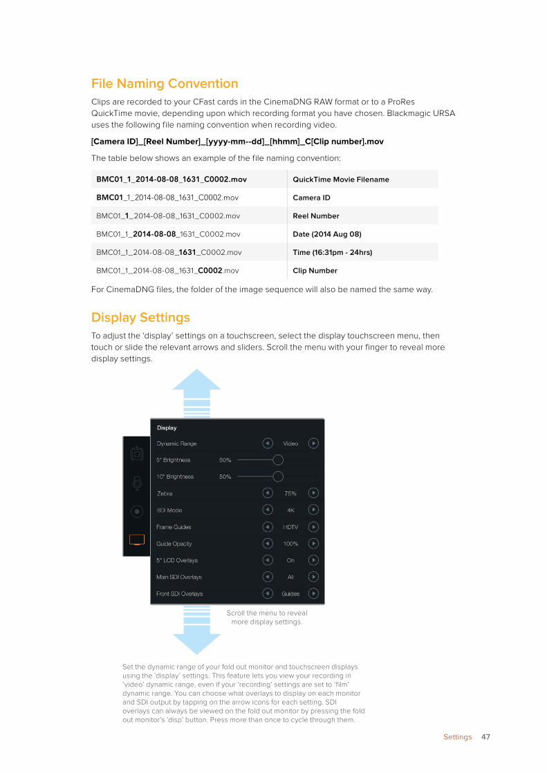
File Naming ConventionClips are recorded to your CFast cards in the CinemaDNG RAW format or to a ProRes QuickTime movie, depending upon which recording format you have chosen. Blackmagic URSA uses the following file naming convention when recording video.
[Camera ID]_[Reel Number]_[yyyy-mm--dd]_[hhmm]_C[Clip number].mov
The table below shows an example of the file naming convention:
BMC01_1_2014-08-08_1631_C0002.mov QuickTime Movie Filename
BMC01_1_2014-08-08_1631_C0002.mov Camera ID
BMC01_1_2014-08-08_1631_C0002.mov Reel Number
BMC01_1_2014-08-08_1631_C0002.mov Date (2014 Aug 08)
BMC01_1_2014-08-08_1631_C0002.mov Time (16:31pm - 24hrs)
BMC01_1_2014-08-08_1631_C0002.mov Clip Number
For CinemaDNG files, the folder of the image sequence will also be named the same way.
Display SettingsTo adjust the ‘display’ settings on a touchscreen, select the display touchscreen menu, then touch or slide the relevant arrows and sliders. Scroll the menu with your finger to reveal more display settings.
Set the dynamic range of your fold out monitor and touchscreen displays using the ‘display’ settings. This feature lets you view your recording in ‘video’ dynamic range, even if your ‘recording’ settings are set to ‘film’ dynamic range. You can choose what overlays to display on each monitor and SDI output by tapping on the arrow icons for each setting. SDI overlays can always be viewed on the fold out monitor by pressing the fold out monitor’s ‘disp’ button. Press more than once to cycle through them.
Scroll the menu to reveal more display settings.
47Settings
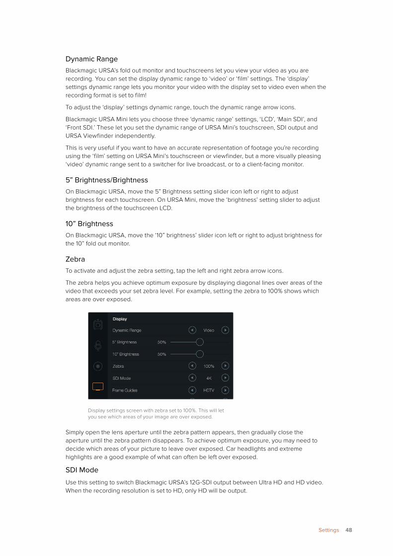
Dynamic RangeBlackmagic URSA’s fold out monitor and touchscreens let you view your video as you are recording. You can set the display dynamic range to ‘video’ or ‘film’ settings. The ‘display’ settings dynamic range lets you monitor your video with the display set to video even when the recording format is set to film!
To adjust the ‘display’ settings dynamic range, touch the dynamic range arrow icons.
Blackmagic URSA Mini lets you choose three ‘dynamic range’ settings, ‘LCD’, ‘Main SDI’, and ‘Front SDI.’ These let you set the dynamic range of URSA Mini’s touchscreen, SDI output and URSA Viewfinder independently.
This is very useful if you want to have an accurate representation of footage you’re recording using the ‘film’ setting on URSA Mini’s touchscreen or viewfinder, but a more visually pleasing ‘video’ dynamic range sent to a switcher for live broadcast, or to a client-facing monitor.
5” Brightness/BrightnessOn Blackmagic URSA, move the 5” Brightness setting slider icon left or right to adjust brightness for each touchscreen. On URSA Mini, move the ‘brightness’ setting slider to adjust the brightness of the touchscreen LCD.
10” BrightnessOn Blackmagic URSA, move the ‘10” brightness’ slider icon left or right to adjust brightness for the 10” fold out monitor.
ZebraTo activate and adjust the zebra setting, tap the left and right zebra arrow icons.
The zebra helps you achieve optimum exposure by displaying diagonal lines over areas of the video that exceeds your set zebra level. For example, setting the zebra to 100% shows which areas are over exposed.
Display settings screen with zebra set to 100%. This will let you see which areas of your image are over exposed.
Simply open the lens aperture until the zebra pattern appears, then gradually close the aperture until the zebra pattern disappears. To achieve optimum exposure, you may need to decide which areas of your picture to leave over exposed. Car headlights and extreme highlights are a good example of what can often be left over exposed.
SDI Mode
Use this setting to switch Blackmagic URSA’s 12G-SDI output between Ultra HD and HD video. When the recording resolution is set to HD, only HD will be output.
48Settings
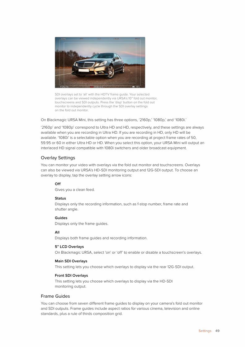
SDI overlays set to ‘all’ with the HDTV frame guide. Your selected overlays can be viewed independently via URSA’s 10” fold out monitor, touchscreens and SDI outputs. Press the ‘disp’ button on the fold out monitor to independently cycle through the SDI overlay settings on the fold out monitor.
On Blackmagic URSA Mini, this setting has three options, ‘2160p,’ ‘1080p,’ and ‘1080i.’
‘2160p’ and ‘1080p’ correspond to Ultra HD and HD, respectively, and these settings are always available when you are recording in Ultra HD. If you are recording in HD, only HD will be available. ‘1080i’ is a selectable option when you are recording at project frame rates of 50, 59.95 or 60 in either Ultra HD or HD. When you select this option, your URSA Mini will output an interlaced HD signal compatible with 1080i switchers and older broadcast equipment.
Overlay SettingsYou can monitor your video with overlays via the fold out monitor and touchscreens. Overlays can also be viewed via URSA’s HD-SDI monitoring output and 12G-SDI output. To choose an overlay to display, tap the overlay setting arrow icons:
OffGives you a clean feed.
StatusDisplays only the recording information, such as f-stop number, frame rate and shutter angle.
GuidesDisplays only the frame guides.
AllDisplays both frame guides and recording information.
5” LCD OverlaysOn Blackmagic URSA, select ‘on’ or ‘off’ to enable or disable a touchscreen’s overlays.
Main SDI OverlaysThis setting lets you choose which overlays to display via the rear 12G-SDI output.
Front SDI OverlaysThis setting lets you choose which overlays to display via the HD-SDI monitoring output.
Frame GuidesYou can choose from seven different frame guides to display on your camera’s fold out monitor and SDI outputs. Frame guides include aspect ratios for various cinema, television and online standards, plus a rule of thirds composition grid.
49Settings
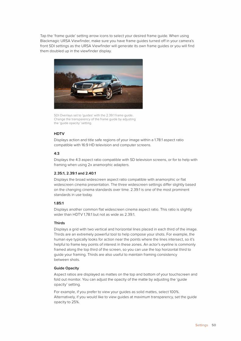
Tap the ‘frame guide’ setting arrow icons to select your desired frame guide. When using Blackmagic URSA Viewfinder, make sure you have frame guides turned off in your camera’s front SDI settings as the URSA Viewfinder will generate its own frame guides or you will find them doubled up in the viewfinder display.
SDI Overlays set to ‘guides’ with the 2.39:1 frame guide. Change the transparency of the frame guide by adjusting the ‘guide opacity’ setting.
HDTV
Displays action and title safe regions of your image within a 1.78:1 aspect ratio compatible with 16:9 HD television and computer screens.
4:3
Displays the 4:3 aspect ratio compatible with SD television screens, or for to help with framing when using 2x anamorphic adapters.
2.35:1, 2.39:1 and 2.40:1
Displays the broad widescreen aspect ratio compatible with anamorphic or flat widescreen cinema presentation. The three widescreen settings differ slightly based on the changing cinema standards over time. 2.39:1 is one of the most prominent standards in use today.
1.85:1
Displays another common flat widescreen cinema aspect ratio. This ratio is slightly wider than HDTV 1.78:1 but not as wide as 2.39:1.
Thirds
Displays a grid with two vertical and horizontal lines placed in each third of the image. Thirds are an extremely powerful tool to help compose your shots. For example, the human eye typically looks for action near the points where the lines intersect, so it’s helpful to frame key points of interest in these zones. An actor’s eyeline is commonly framed along the top third of the screen, so you can use the top horizontal third to guide your framing. Thirds are also useful to maintain framing consistency between shots.
Guide Opacity
Aspect ratios are displayed as mattes on the top and bottom of your touchscreen and fold out monitor. You can adjust the opacity of the matte by adjusting the ‘guide opacity’ setting.
For example, if you prefer to view your guides as solid mattes, select 100%. Alternatively, if you would like to view guides at maximum transparency, set the guide opacity to 25%.
50Settings
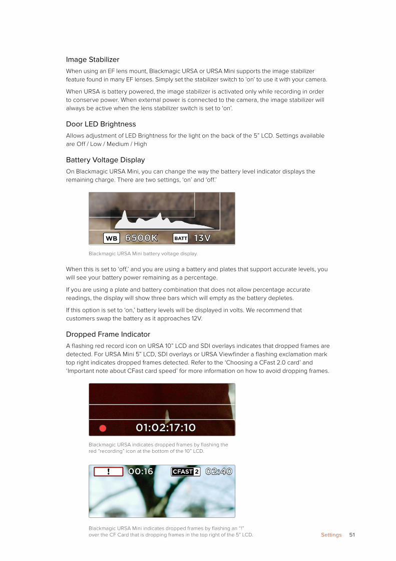
Image StabilizerWhen using an EF lens mount, Blackmagic URSA or URSA Mini supports the image stabilizer feature found in many EF lenses. Simply set the stabilizer switch to ‘on’ to use it with your camera.
When URSA is battery powered, the image stabilizer is activated only while recording in order to conserve power. When external power is connected to the camera, the image stabilizer will always be active when the lens stabilizer switch is set to ‘on’.
Door LED BrightnessAllows adjustment of LED Brightness for the light on the back of the 5” LCD. Settings available are Off / Low / Medium / High
Battery Voltage DisplayOn Blackmagic URSA Mini, you can change the way the battery level indicator displays the remaining charge. There are two settings, ‘on’ and ‘off.’
Blackmagic URSA Mini battery voltage display.
When this is set to ‘off,’ and you are using a battery and plates that support accurate levels, you will see your battery power remaining as a percentage.
If you are using a plate and battery combination that does not allow percentage accurate readings, the display will show three bars which will empty as the battery depletes.
If this option is set to ‘on,’ battery levels will be displayed in volts. We recommend that customers swap the battery as it approaches 12V.
Dropped Frame IndicatorA flashing red record icon on URSA 10” LCD and SDI overlays indicates that dropped frames are detected. For URSA Mini 5” LCD, SDI overlays or URSA Viewfinder a flashing exclamation mark top right indicates dropped frames detected. Refer to the ‘Choosing a CFast 2.0 card’ and ‘Important note about CFast card speed’ for more information on how to avoid dropping frames.
Blackmagic URSA indicates dropped frames by flashing the red “recording” icon at the bottom of the 10” LCD.
Blackmagic URSA Mini indicates dropped frames by flashing an “!” over the CF Card that is dropping frames in the top right of the 5” LCD. 51Settings
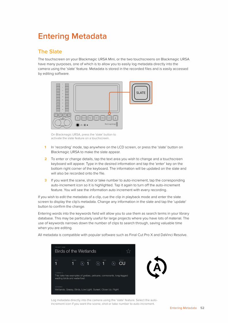
Entering Metadata
The SlateThe touchscreen on your Blackmagic URSA Mini, or the two touchscreens on Blackmagic URSA have many purposes, one of which is to allow you to easily log metadata directly into the camera using the ‘slate’ feature. Metadata is stored in the recorded files and is easily accessed by editing software.
On Blackmagic URSA, press the ‘slate’ button to activate the slate feature on a touchscreen.
1 In ‘recording’ mode, tap anywhere on the LCD screen, or press the ‘slate’ button on Blackmagic URSA to make the slate appear.
2 To enter or change details, tap the text area you wish to change and a touchscreen keyboard will appear. Type in the desired information and tap the ‘enter’ key on the bottom right corner of the keyboard. The information will be updated on the slate and will also be recorded onto the file.
3 If you want the scene, shot or take number to auto-increment, tap the corresponding auto-increment icon so it is highlighted. Tap it again to turn off the auto-increment feature. You will see the information auto increment with every recording.
If you wish to edit the metadata of a clip, cue the clip in playback mode and enter the slate screen to display the clip’s metadata. Change any information in the slate and tap the ‘update’ button to confirm the change.
Entering words into the keywords field will allow you to use them as search terms in your library database. This may be particularly useful for large projects where you have lots of material. The use of keywords narrows down the number of clips to search through, saving valuable time when you are editing.
All metadata is compatible with popular software such as Final Cut Pro X and DaVinci Resolve.
Log metadata directly into the camera using the ‘slate’ feature. Select the auto-increment icon if you want the scene, shot or take number to auto-increment.
REC
ZOOM
DISP
PGM
1
CFAST
IRIS
FOCUS
REC
IRIS
FOCUS PEAK DISP MENU SLATE
2
IRIS
SDI OUT
0
-6
-12
-18
-24
-30
-36
-42
-48
L R
SDI IN
REF IN
TIMECODE IN
TIMECODE OUT
12V
CH1SOLO
CH1MUTE
CH2MUTE
CH2SOLO
FOCUS PEAK DISP MENU SLATE
PU
SHP
USH
PU
SH
REC
ZOOM
DISP
PGM
1
CFAST
IRIS
FOCUS
REC
IRIS
FOCUS PEAK DISP MENU SLATE
2
IRIS
SDI OUT
0
-6
-12
-18
-24
-30
-36
-42
-48
L R
SDI IN
REF IN
TIMECODE IN
TIMECODE OUT
12V
CH1SOLO
CH1MUTE
CH2MUTE
CH2SOLO
FOCUS PEAK DISP MENU SLATE
PU
SHP
USH
PU
SH
52Entering Metadata
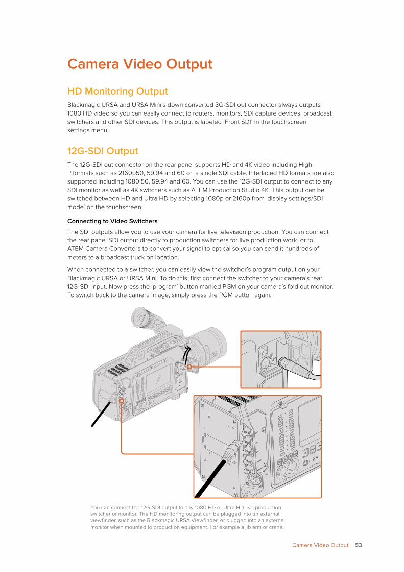
Camera Video Output
HD Monitoring OutputBlackmagic URSA and URSA Mini’s down converted 3G-SDI out connector always outputs 1080 HD video so you can easily connect to routers, monitors, SDI capture devices, broadcast switchers and other SDI devices. This output is labeled ‘Front SDI’ in the touchscreen settings menu.
12G-SDI OutputThe 12G-SDI out connector on the rear panel supports HD and 4K video including High P formats such as 2160p50, 59.94 and 60 on a single SDI cable. Interlaced HD formats are also supported including 1080i50, 59.94 and 60. You can use the 12G-SDI output to connect to any SDI monitor as well as 4K switchers such as ATEM Production Studio 4K. This output can be switched between HD and Ultra HD by selecting 1080p or 2160p from ‘display settings/SDI mode’ on the touchscreen.
Connecting to Video Switchers
The SDI outputs allow you to use your camera for live television production. You can connect the rear panel SDI output directly to production switchers for live production work, or to ATEM Camera Converters to convert your signal to optical so you can send it hundreds of meters to a broadcast truck on location.
When connected to a switcher, you can easily view the switcher’s program output on your Blackmagic URSA or URSA Mini. To do this, first connect the switcher to your camera’s rear 12G-SDI input. Now press the ‘program’ button marked PGM on your camera’s fold out monitor. To switch back to the camera image, simply press the PGM button again.
You can connect the 12G-SDI output to any 1080 HD or Ultra HD live production switcher or monitor. The HD monitoring output can be plugged into an external viewfinder, such as the Blackmagic URSA Viewfinder, or plugged into an external monitor when mounted to production equipment. For example a jib arm or crane.
0
-6
-12
-18
-24
-30
-36
-42
-48
REF IN
SDI IN
SDI OUT
TIMECODE IN
TIMECODE OUT
CH1SOLO
L
RCH1
MUTE
CH2SOLO
CH2MUTE IRIS
FOCUS
PEAK
DISP
MENU
SLATE
AUDIO IN
1
2
12V
IRIS
FOCUS
PEAK
DISP
AUDIO IN
MENU
SLATE
CH1
SOLO
CH1
MUTE
CH2
SOLO
CH1
MUTE
SDI OUT
SDI IN
REF IN
TIMECODE IN
TIMECODE O
UTL
R
0
-6
-12
-18
-24
-30
-36
-42
-48
0
-6
-12
-18
-24
-30
-36
-42
-48
REF IN
SDI IN
SDI OUT
TIMECODE IN
TIMECODE OUT
CH1SOLO
L
RCH1
MUTE
CH2SOLO
CH2MUTE IRIS
FOCUS
PEAK
DISP
MENU
SLATE
AUDIO IN
1
2
12V
53Camera Video Output
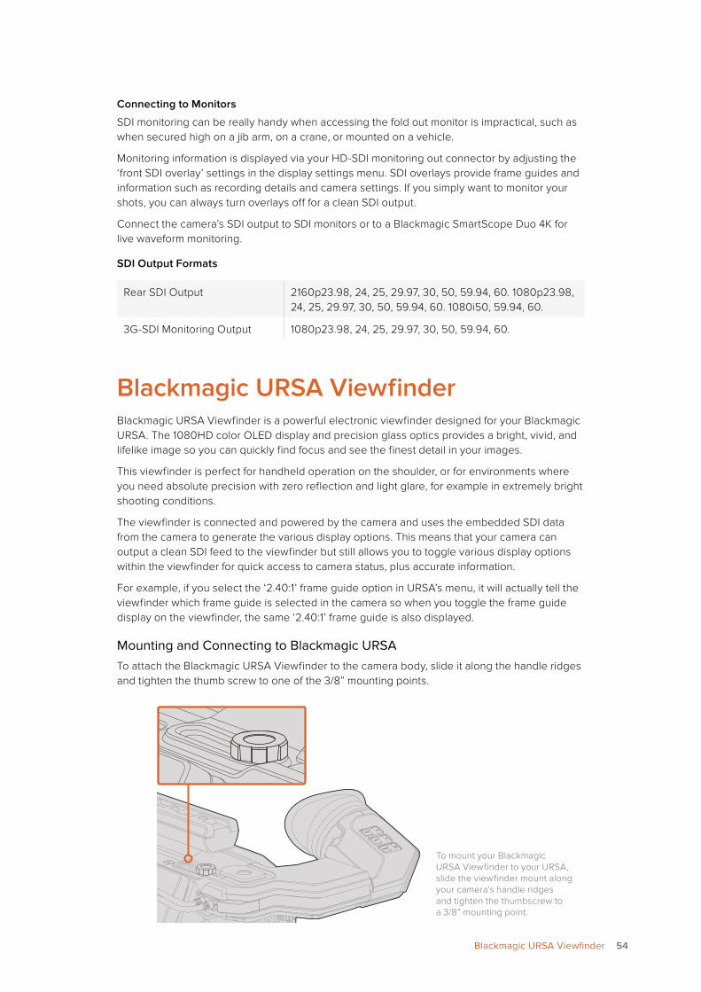
Connecting to Monitors
SDI monitoring can be really handy when accessing the fold out monitor is impractical, such as when secured high on a jib arm, on a crane, or mounted on a vehicle.
Monitoring information is displayed via your HD-SDI monitoring out connector by adjusting the ‘front SDI overlay’ settings in the display settings menu. SDI overlays provide frame guides and information such as recording details and camera settings. If you simply want to monitor your shots, you can always turn overlays off for a clean SDI output.
Connect the camera’s SDI output to SDI monitors or to a Blackmagic SmartScope Duo 4K for live waveform monitoring.
SDI Output Formats
Rear SDI Output 2160p23.98, 24, 25, 29.97, 30, 50, 59.94, 60. 1080p23.98, 24, 25, 29.97, 30, 50, 59.94, 60. 1080i50, 59.94, 60.
3G-SDI Monitoring Output 1080p23.98, 24, 25, 29.97, 30, 50, 59.94, 60.
Blackmagic URSA ViewfinderBlackmagic URSA Viewfinder is a powerful electronic viewfinder designed for your Blackmagic URSA. The 1080HD color OLED display and precision glass optics provides a bright, vivid, and lifelike image so you can quickly find focus and see the finest detail in your images.
This viewfinder is perfect for handheld operation on the shoulder, or for environments where you need absolute precision with zero reflection and light glare, for example in extremely bright shooting conditions.
The viewfinder is connected and powered by the camera and uses the embedded SDI data from the camera to generate the various display options. This means that your camera can output a clean SDI feed to the viewfinder but still allows you to toggle various display options within the viewfinder for quick access to camera status, plus accurate information.
For example, if you select the ‘2.40:1’ frame guide option in URSA’s menu, it will actually tell the viewfinder which frame guide is selected in the camera so when you toggle the frame guide display on the viewfinder, the same ‘2.40:1’ frame guide is also displayed.
Mounting and Connecting to Blackmagic URSATo attach the Blackmagic URSA Viewfinder to the camera body, slide it along the handle ridges and tighten the thumb screw to one of the 3/8” mounting points.
SDI OUT
12V OUT
IRIS
L
R
REF IN
TIMECODE IN
TIMECODE OUT
12V CH1SOLOCH1MUTE
CH2MUTE
CH2SOLO
FOCUS
PEAK
DISP
MENU
SLATE
0
-6
-12
-18
-24
-30
-36
-42
-48
SDI OUT
SDI IN
AUDIO IN
2
ZOOMF1
F2
F3
DISP
PEAK
SDI OUT
12V OUT
IRIS
L
R
REF IN
TIMECODE IN
TIMECODE OUT
12V CH1SOLOCH1MUTE
CH2MUTE
CH2SOLO
FOCUS
PEAK
DISP
MENU
SLATE
0
-6
-12
-18
-24
-30
-36
-42
-48
SDI OUT
SDI IN
AUDIO IN
2
ZOOMF1
F2
F3
DISP
PEAK
To mount your Blackmagic URSA Viewfinder to your URSA, slide the viewfinder mount along your camera’s handle ridges and tighten the thumbscrew to a 3/8” mounting point.
54Blackmagic URSA Viewfinder
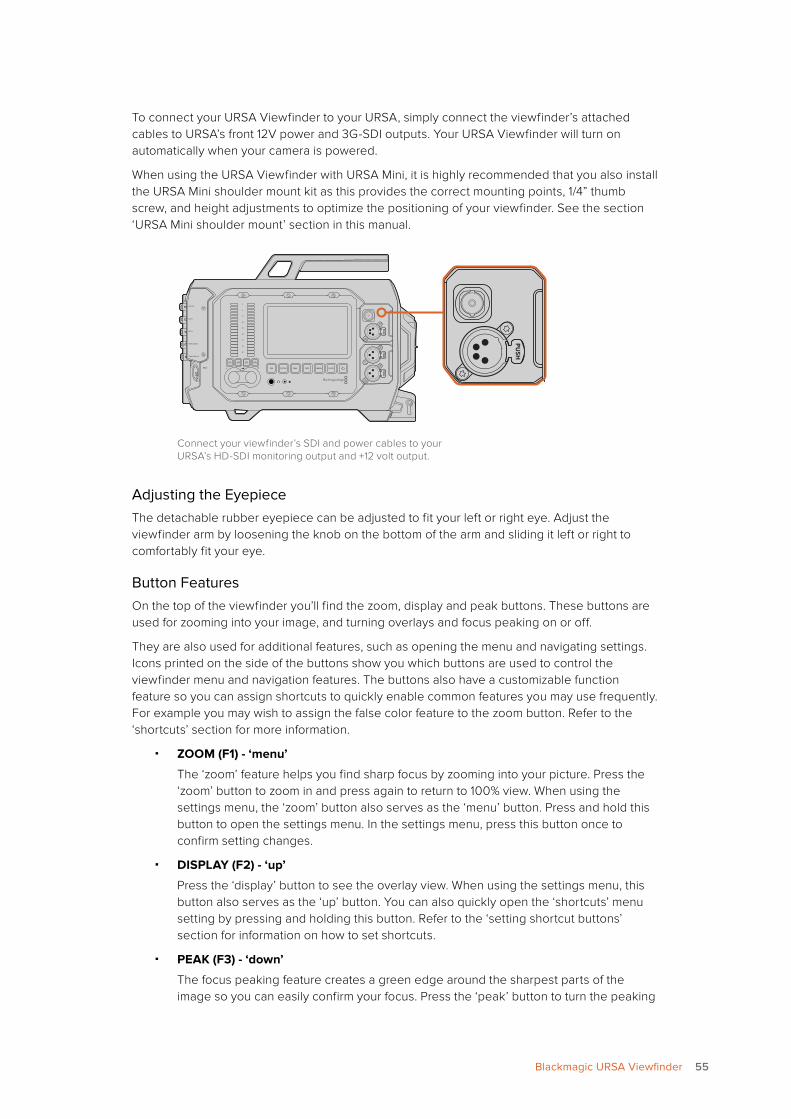
To connect your URSA Viewfinder to your URSA, simply connect the viewfinder’s attached cables to URSA’s front 12V power and 3G-SDI outputs. Your URSA Viewfinder will turn on automatically when your camera is powered.
When using the URSA Viewfinder with URSA Mini, it is highly recommended that you also install the URSA Mini shoulder mount kit as this provides the correct mounting points, 1/4” thumb screw, and height adjustments to optimize the positioning of your viewfinder. See the section ‘URSA Mini shoulder mount’ section in this manual.
Connect your viewfinder’s SDI and power cables to your URSA’s HD-SDI monitoring output and +12 volt output.
Adjusting the EyepieceThe detachable rubber eyepiece can be adjusted to fit your left or right eye. Adjust the viewfinder arm by loosening the knob on the bottom of the arm and sliding it left or right to comfortably fit your eye.
Button Features On the top of the viewfinder you’ll find the zoom, display and peak buttons. These buttons are used for zooming into your image, and turning overlays and focus peaking on or off.
They are also used for additional features, such as opening the menu and navigating settings. Icons printed on the side of the buttons show you which buttons are used to control the viewfinder menu and navigation features. The buttons also have a customizable function feature so you can assign shortcuts to quickly enable common features you may use frequently. For example you may wish to assign the false color feature to the zoom button. Refer to the ‘shortcuts’ section for more information.
� ZOOM (F1) - ‘menu’
The ‘zoom’ feature helps you find sharp focus by zooming into your picture. Press the ‘zoom’ button to zoom in and press again to return to 100% view. When using the settings menu, the ‘zoom’ button also serves as the ‘menu’ button. Press and hold this button to open the settings menu. In the settings menu, press this button once to confirm setting changes.
� DISPLAY (F2) - ‘up’
Press the ‘display’ button to see the overlay view. When using the settings menu, this button also serves as the ‘up’ button. You can also quickly open the ‘shortcuts’ menu setting by pressing and holding this button. Refer to the ‘setting shortcut buttons’ section for information on how to set shortcuts.
� PEAK (F3) - ‘down’
The focus peaking feature creates a green edge around the sharpest parts of the image so you can easily confirm your focus. Press the ‘peak’ button to turn the peaking
REC
ZOOM
DISP
PGM
1
CFAST
IRIS
FOCUS
REC
IRIS
FOCUS PEAK DISP MENU SLATE
2
IRIS
SDI OUT
0
-6
-12
-18
-24
-30
-36
-42
-48
L R
SDI IN
REF IN
TIMECODE IN
TIMECODE OUT
12V
CH1SOLO
CH1MUTE
CH2MUTE
CH2SOLO
FOCUS PEAK DISP MENU SLATE
PU
SHP
USH
PU
SH
REC
ZOOM
DISP
PGM
1
CFAST
IRIS
FOCUS
REC
IRIS
FOCUS PEAK DISP MENU SLATE
2
IRIS
SDI OUT
0
-6
-12
-18
-24
-30
-36
-42
-48
L R
SDI IN
REF IN
TIMECODE IN
TIMECODE OUT
12V
CH1SOLO
CH1MUTE
CH2MUTE
CH2SOLO
FOCUS PEAK DISP MENU SLATE
PU
SHP
USH
PU
SH
55Blackmagic URSA Viewfinder
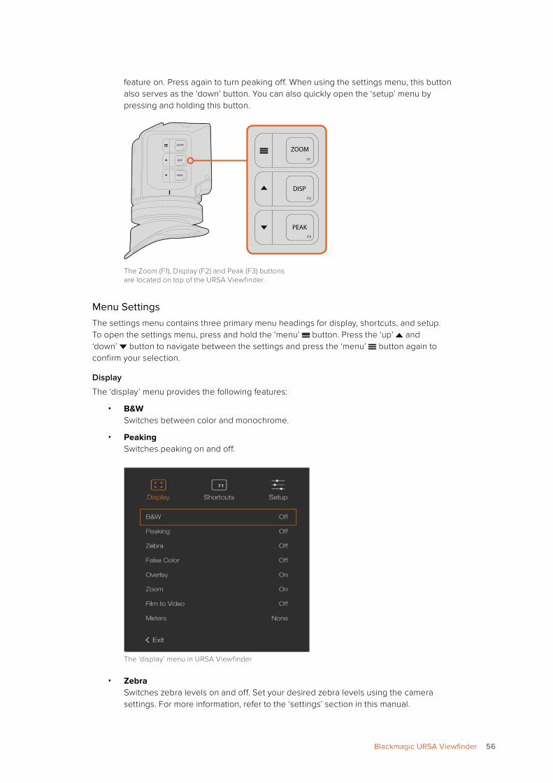
feature on. Press again to turn peaking off. When using the settings menu, this button also serves as the ‘down’ button. You can also quickly open the ‘setup’ menu by pressing and holding this button.
The Zoom (F1), Display (F2) and Peak (F3) buttons are located on top of the URSA Viewfinder.
Menu SettingsThe settings menu contains three primary menu headings for display, shortcuts, and setup. To open the settings menu, press and hold the ‘menu’ button. Press the ‘up’ and ‘down’ button to navigate between the settings and press the ‘menu’ button again to confirm your selection.
Display
The ‘display’ menu provides the following features:
� B&W Switches between color and monochrome.
� Peaking Switches peaking on and off.
The ‘display’ menu in URSA Viewfinder
� Zebra Switches zebra levels on and off. Set your desired zebra levels using the camera settings. For more information, refer to the ‘settings’ section in this manual.
ZOOMF1
F2
F3
DISP
PEAK
ZOOMF1
F2
F3
DISP
PEAK
56Blackmagic URSA Viewfinder
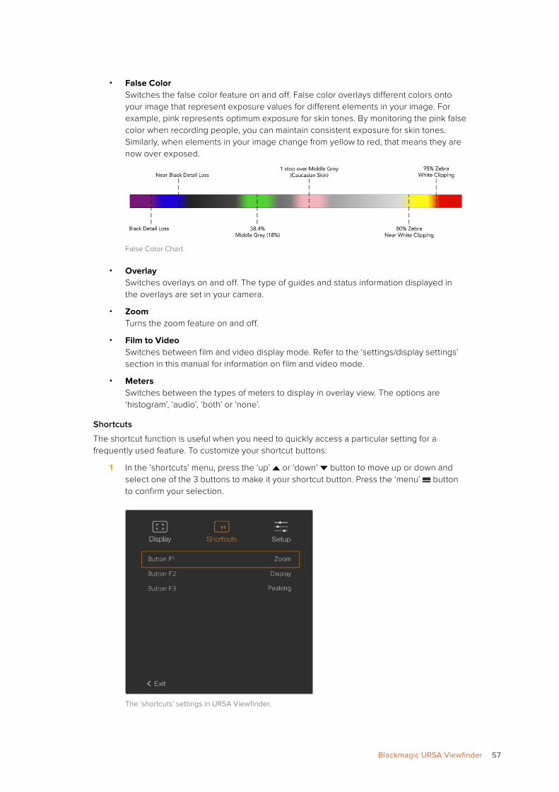
� False Color Switches the false color feature on and off. False color overlays different colors onto your image that represent exposure values for different elements in your image. For example, pink represents optimum exposure for skin tones. By monitoring the pink false color when recording people, you can maintain consistent exposure for skin tones. Similarly, when elements in your image change from yellow to red, that means they are now over exposed.
False Color Chart
� Overlay Switches overlays on and off. The type of guides and status information displayed in the overlays are set in your camera.
� Zoom Turns the zoom feature on and off.
� Film to Video Switches between film and video display mode. Refer to the ‘settings/display settings’ section in this manual for information on film and video mode.
� Meters Switches between the types of meters to display in overlay view. The options are ‘histogram’, ‘audio’, ‘both’ or ‘none’.
Shortcuts
The shortcut function is useful when you need to quickly access a particular setting for a frequently used feature. To customize your shortcut buttons:
1 In the ‘shortcuts’ menu, press the ‘up’ or ‘down’ button to move up or down and select one of the 3 buttons to make it your shortcut button. Press the ‘menu’ button to confirm your selection.
The ‘shortcuts’ settings in URSA Viewfinder.
57Blackmagic URSA Viewfinder
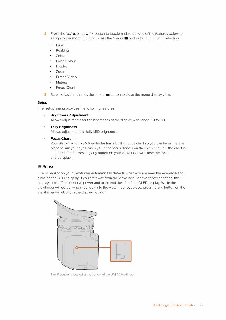
2 Press the ‘up’ or ‘down’ v button to toggle and select one of the features below to assign to the shortcut button. Press the ‘menu’ button to confirm your selection.
� B&W � Peaking � Zebra � False Colour � Display � Zoom � Film to Video � Meters � Focus Chart
3 Scroll to ‘exit’ and press the ‘menu’ button to close the menu display view.
Setup
The ‘setup’ menu provides the following features:
� Brightness AdjustmentAllows adjustments for the brightness of the display with range -10 to +10.
� Tally Brightness Allows adjustments of tally LED brightness.
� Focus Chart Your Blackmagic URSA Viewfinder has a built in focus chart so you can focus the eye piece to suit your eyes. Simply turn the focus diopter on the eyepiece until the chart is in perfect focus. Pressing any button on your viewfinder will close the focus chart display.
IR SensorThe IR Sensor on your viewfinder automatically detects when you are near the eyepiece and turns on the OLED display. If you are away from the viewfinder for over a few seconds, the display turns off to conserve power and to extend the life of the OLED display. While the viewfinder will detect when you look into the viewfinder eyepiece, pressing any button on the viewfinder will also turn the display back on.
The IR sensor is located at the bottom of the URSA Viewfinder.
58Blackmagic URSA Viewfinder

Deliberately blocking or covering the IR sensor could cause the viewfinder’s display to remain powered for prolonged periods of time. This could decrease the lifespan of the display and cause image retention if high contrast images or frame guides are displayed on the viewfinder.
Updating URSA Viewfinder’s Internal SoftwareUpdate your viewfinder using the Blackmagic Camera Setup utility software. The viewfinder will need to be powered when updating, so we recommend keeping the viewfinder connected to your URSA during the update process. This also means your URSA will need to supply consistent power, so be sure to plug into external power.
Connect your computer to the small USB connection located at the front of your viewfinder, near the eyepiece. When Blackmagic Camera Utility is launched and your viewfinder is connected to your computer, you will be prompted to update if your computer detects that your viewfinder is using an older version. Follow the on screen prompts to update your viewfinder’s internal software. Refer to the ‘Blackmagic Camera Setup Utility’ section in this manual for more information.
We recommend updating all your Blackmagic URSA equipment at the same time for optimized performance.
Mounting Batteries
Mounting V-mount or Gold Mount BatteriesYou can easily mount industry standard V-mount or gold mount batteries to Blackmagic URSA or URSA Mini.
Connecting a third party battery plate lets you mount V-mount or gold mount batteries.
IRIS
SDI OUT
SDI IN
REF IN
TIMECODE IN
L
R
TIMECODE O
UT
+12V
CH1
SOLO
CH1
MUTE
CH2
SOLO
CH1
MUTE
FOCUS
PEAK
DISP
AUDIO IN
12V OUT
SDI OUT
MENU
SLATE
0
-6
-12
-18
-24
-30
-36
-42
-48
59Mounting Batteries
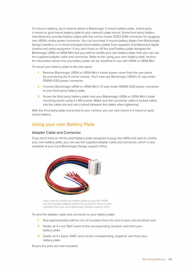
To mount a battery, you’ll need to attach a Blackmagic V-mount battery plate, a third party V-mount or gold mount battery plate to your camera’s plate mount. Some third party battery manufacturers provide battery plates with the correct molex 51353-1200 connector for plugging into URSA’s molex power connector. You can purchase V-mount battery plates from Blackmagic Design resellers, or V-mount and gold mount battery plates from suppliers of professional digital cinema and video equipment. If you don’t have an off the shelf battery plate designed for Blackmagic URSA or URSA Mini and you want to modify your own battery plate, then you can use the supplied adapter cable and connector. Refer to the ‘using your own battery plate’ section for information about how any battery plate can be modified to use with URSA or URSA Mini.
To mount your battery plate to the rear panel:
1 Remove Blackmagic URSA or URSA Mini’s molex power cover from the rear panel by unscrewing the 4 corner screws. You’ll now see Blackmagic URSA’s 12 way molex 55959-1230 power connector.
2 Connect Blackmagic URSA or URSA Mini’s 12 way molex 55959-1230 power connector to your third party battery plate.
3 Screw the third party battery plate onto your Blackmagic URSA or URSA Mini’s plate mounting points using 4 x M3 screws. Make sure the connector cable is tucked safely into the cable slot and not crushed between the plates when tightening.
With the third party plate connected to your camera, you can now mount a V-mount or gold mount battery.
Using your own Battery Plate
Adapter Cable and ConnectorIf you don’t have an off the shelf battery plate designed to plug into URSA and want to modify your own battery plate, you can use the supplied adapter cable and connector, which is also available at your local Blackmagic Design support office.
If you need to modify any battery plate to plug into URSA, use the supplied adapter cable and connector, which is also available from your local Blackmagic Design support office.
To wire the adapter cable and connector to your battery plate:
1 Strip approximately half an inch of insulation from the end of each red and black wire.
2 Solder all 4 x red ‘Batt’ wires to the corresponding ‘positive’ wire from your battery plate.
3 Solder all 4 x black ‘GND’ wires to the corresponding ‘negative’ wire from your battery plate.
Ensure the joins are well insulated.
60Mounting Batteries
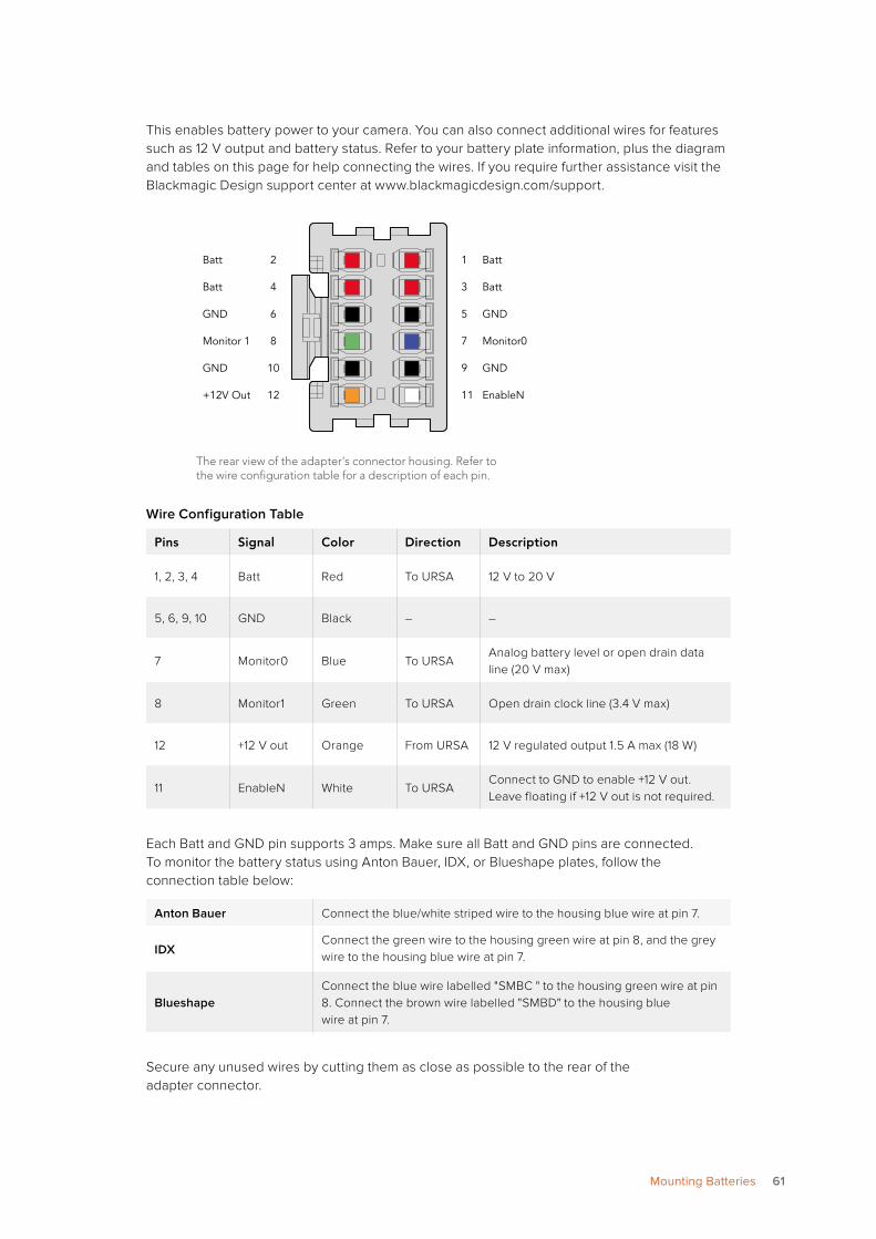
This enables battery power to your camera. You can also connect additional wires for features such as 12 V output and battery status. Refer to your battery plate information, plus the diagram and tables on this page for help connecting the wires. If you require further assistance visit the Blackmagic Design support center at www.blackmagicdesign.com/support.
The rear view of the adapter’s connector housing. Refer to the wire configuration table for a description of each pin.
Wire Configuration Table
Pins Signal Color Direction Description
1, 2, 3, 4 Batt Red To URSA 12 V to 20 V
5, 6, 9, 10 GND Black – –
7 Monitor0 Blue To URSAAnalog battery level or open drain data line (20 V max)
8 Monitor1 Green To URSA Open drain clock line (3.4 V max)
12 +12 V out Orange From URSA 12 V regulated output 1.5 A max (18 W)
11 EnableN White To URSAConnect to GND to enable +12 V out. Leave floating if +12 V out is not required.
Each Batt and GND pin supports 3 amps. Make sure all Batt and GND pins are connected. To monitor the battery status using Anton Bauer, IDX, or Blueshape plates, follow the connection table below:
Anton Bauer Connect the blue/white striped wire to the housing blue wire at pin 7.
IDXConnect the green wire to the housing green wire at pin 8, and the grey wire to the housing blue wire at pin 7.
BlueshapeConnect the blue wire labelled "SMBC " to the housing green wire at pin 8. Connect the brown wire labelled "SMBD" to the housing blue wire at pin 7.
Secure any unused wires by cutting them as close as possible to the rear of the adapter connector.
Batt 2
Batt 4
GND 6
Monitor 1 8
GND 10
+12V Out 12
1 Batt
3 Batt
5 GND
7 Monitor0
9 GND
11 EnableN
61Mounting Batteries
Using DaVinci Resolve
Shooting with your Blackmagic URSA is only part of the process of creating film and television content, and just as important is the process of media backup and management as well as editing, color correction and encoding final master files. Your Blackmagic URSA or URSA Mini includes a version of DaVinci Resolve Studio for Mac OS X and Windows so you have a complete solution for shooting and post production!
After connecting your CFast card to your computer, you can use DaVinci Resolve’s ‘clone’ tool, in the ‘media’ page, to create running backups as you shoot. This is recommended as any type of media is susceptible to becoming damaged or developing a fault so creating backups ensures your shots will be immune to loss. Once you have used DaVinci Resolve to back up your media, you can then add your clips to the DaVinci media pool, then edit, color correct, and finish your production without ever having to leave DaVinci Resolve.
Because Blackmagic URSA and URSA Mini shoots a much wider dynamic range than regular video cameras, DaVinci Resolve will help you adjust your shots to get any kind of look you are after. DaVinci Resolve is the same tool used on most major blockbuster movies, so it’s much more than a simple NLE software tool, as it has extremely advanced technology built in for high end digital film. You get the advantage of this technology when you use DaVinci Resolve to edit and color correct your work.
Included here is information on how to get started using DaVinci Resolve with your camera files. Of course, DaVinci Resolve is extremely advanced and includes a lot more features than you immediately see when first looking at its user interface. To learn more about how to use DaVinci Resolve, please check for the DaVinci Resolve instruction manual pdf file on the DaVinci Resolve software disk, or check online for the many training courses and tutorial videos available.
Importing your Clips To start editing your clips, you’ll first need to import them into the media pool:
1 Launch DaVinci Resolve. If this is the first time you’ve opened DaVinci Resolve, wait for the Project Manager to appear, and double click the ‘untitled project’ icon in the project manager window. If the log in window appears, that means you have the Resolve multi-user environment enabled. In this case, click Add New at the bottom left of the log in window and create a new user by entering a user name and clicking Setup New User. Then double-click the user icon to proceed to the Project Manager.
2 You’ll now see the ‘media’ page with a ‘media storage’ browser at the top left. The ‘media storage’ browser displays all your linked media folders from where you’ll drag your clips and drop them into the media pool.
62Using DaVinci Resolve
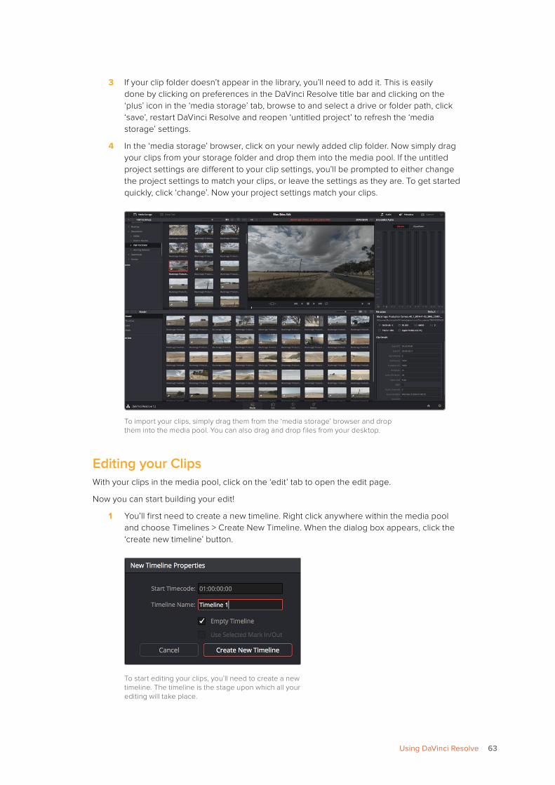
3 If your clip folder doesn’t appear in the library, you’ll need to add it. This is easily done by clicking on preferences in the DaVinci Resolve title bar and clicking on the ‘plus’ icon in the ‘media storage’ tab, browse to and select a drive or folder path, click ‘save’, restart DaVinci Resolve and reopen ‘untitled project’ to refresh the ‘media storage’ settings.
4 In the ‘media storage’ browser, click on your newly added clip folder. Now simply drag your clips from your storage folder and drop them into the media pool. If the untitled project settings are different to your clip settings, you’ll be prompted to either change the project settings to match your clips, or leave the settings as they are. To get started quickly, click ‘change’. Now your project settings match your clips.
To import your clips, simply drag them from the ‘media storage’ browser and drop them into the media pool. You can also drag and drop files from your desktop.
Editing your Clips With your clips in the media pool, click on the ‘edit’ tab to open the edit page.
Now you can start building your edit!
1 You’ll first need to create a new timeline. Right click anywhere within the media pool and choose Timelines > Create New Timeline. When the dialog box appears, click the ‘create new timeline’ button.
To start editing your clips, you’ll need to create a new timeline. The timeline is the stage upon which all your editing will take place.
63Using DaVinci Resolve
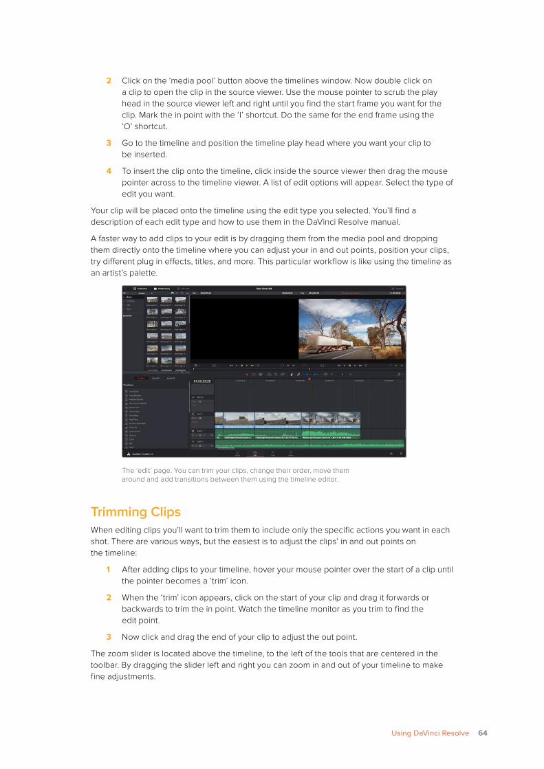
2 Click on the ‘media pool’ button above the timelines window. Now double click on a clip to open the clip in the source viewer. Use the mouse pointer to scrub the play head in the source viewer left and right until you find the start frame you want for the clip. Mark the in point with the ‘I’ shortcut. Do the same for the end frame using the ‘O’ shortcut.
3 Go to the timeline and position the timeline play head where you want your clip to be inserted.
4 To insert the clip onto the timeline, click inside the source viewer then drag the mouse pointer across to the timeline viewer. A list of edit options will appear. Select the type of edit you want.
Your clip will be placed onto the timeline using the edit type you selected. You’ll find a description of each edit type and how to use them in the DaVinci Resolve manual.
A faster way to add clips to your edit is by dragging them from the media pool and dropping them directly onto the timeline where you can adjust your in and out points, position your clips, try different plug in effects, titles, and more. This particular workflow is like using the timeline as an artist’s palette.
The ‘edit’ page. You can trim your clips, change their order, move them around and add transitions between them using the timeline editor.
Trimming ClipsWhen editing clips you’ll want to trim them to include only the specific actions you want in each shot. There are various ways, but the easiest is to adjust the clips’ in and out points on the timeline:
1 After adding clips to your timeline, hover your mouse pointer over the start of a clip until the pointer becomes a ‘trim’ icon.
2 When the ‘trim’ icon appears, click on the start of your clip and drag it forwards or backwards to trim the in point. Watch the timeline monitor as you trim to find the edit point.
3 Now click and drag the end of your clip to adjust the out point.
The zoom slider is located above the timeline, to the left of the tools that are centered in the toolbar. By dragging the slider left and right you can zoom in and out of your timeline to make fine adjustments.
64Using DaVinci Resolve
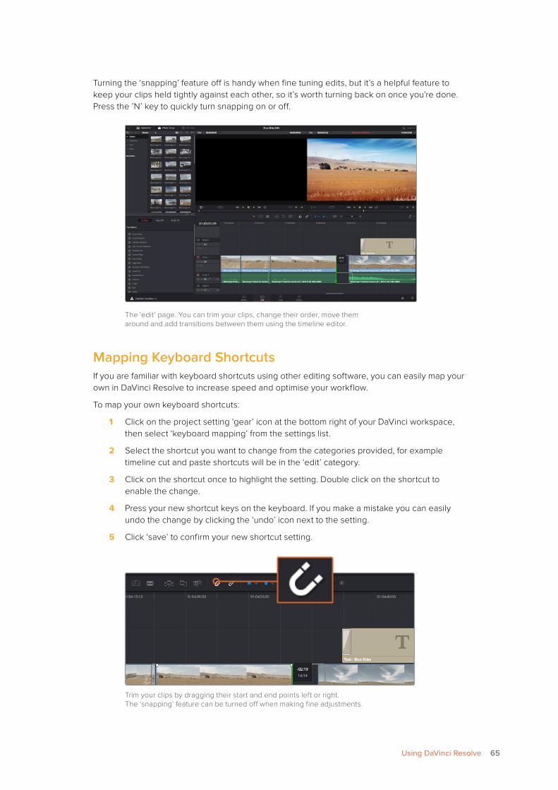
Turning the ‘snapping’ feature off is handy when fine tuning edits, but it’s a helpful feature to keep your clips held tightly against each other, so it’s worth turning back on once you’re done. Press the ’N’ key to quickly turn snapping on or off.
The ‘edit’ page. You can trim your clips, change their order, move them around and add transitions between them using the timeline editor.
Mapping Keyboard ShortcutsIf you are familiar with keyboard shortcuts using other editing software, you can easily map your own in DaVinci Resolve to increase speed and optimise your workflow.
To map your own keyboard shortcuts:
1 Click on the project setting ‘gear’ icon at the bottom right of your DaVinci workspace, then select ‘keyboard mapping’ from the settings list.
2 Select the shortcut you want to change from the categories provided, for example timeline cut and paste shortcuts will be in the ‘edit’ category.
3 Click on the shortcut once to highlight the setting. Double click on the shortcut to enable the change.
4 Press your new shortcut keys on the keyboard. If you make a mistake you can easily undo the change by clicking the ‘undo’ icon next to the setting.
5 Click ‘save’ to confirm your new shortcut setting.
Trim your clips by dragging their start and end points left or right. The ‘snapping’ feature can be turned off when making fine adjustments.
65Using DaVinci Resolve
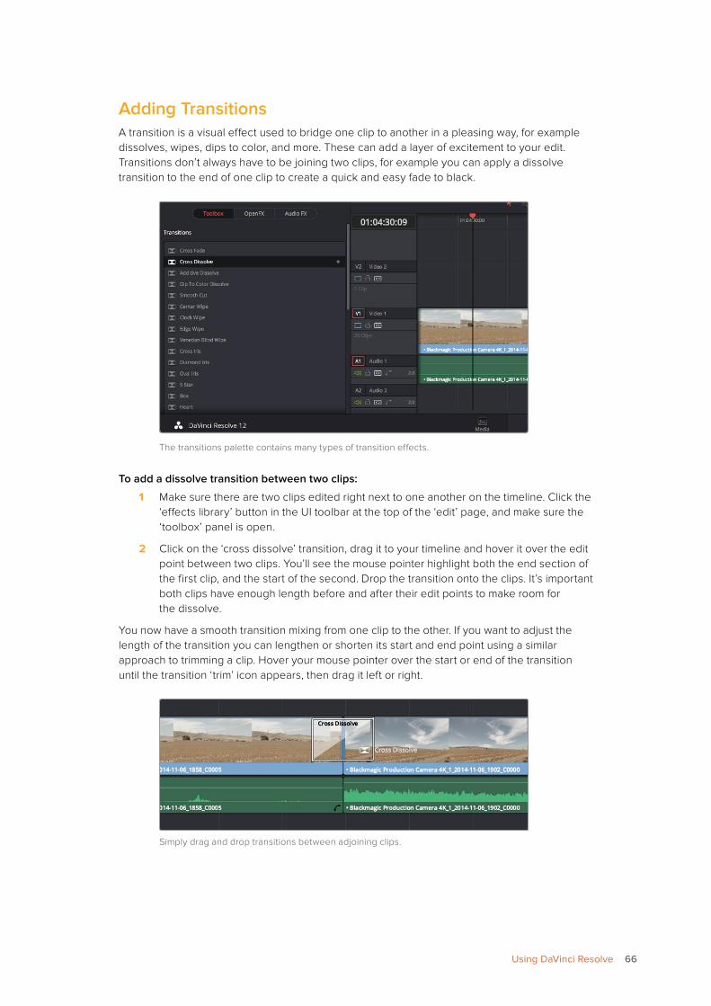
Adding TransitionsA transition is a visual effect used to bridge one clip to another in a pleasing way, for example dissolves, wipes, dips to color, and more. These can add a layer of excitement to your edit. Transitions don’t always have to be joining two clips, for example you can apply a dissolve transition to the end of one clip to create a quick and easy fade to black.
The transitions palette contains many types of transition effects.
To add a dissolve transition between two clips:
1 Make sure there are two clips edited right next to one another on the timeline. Click the ‘effects library’ button in the UI toolbar at the top of the ‘edit’ page, and make sure the ‘toolbox’ panel is open.
2 Click on the ‘cross dissolve’ transition, drag it to your timeline and hover it over the edit point between two clips. You’ll see the mouse pointer highlight both the end section of the first clip, and the start of the second. Drop the transition onto the clips. It’s important both clips have enough length before and after their edit points to make room for the dissolve.
You now have a smooth transition mixing from one clip to the other. If you want to adjust the length of the transition you can lengthen or shorten its start and end point using a similar approach to trimming a clip. Hover your mouse pointer over the start or end of the transition until the transition ‘trim’ icon appears, then drag it left or right.
Simply drag and drop transitions between adjoining clips.
66Using DaVinci Resolve
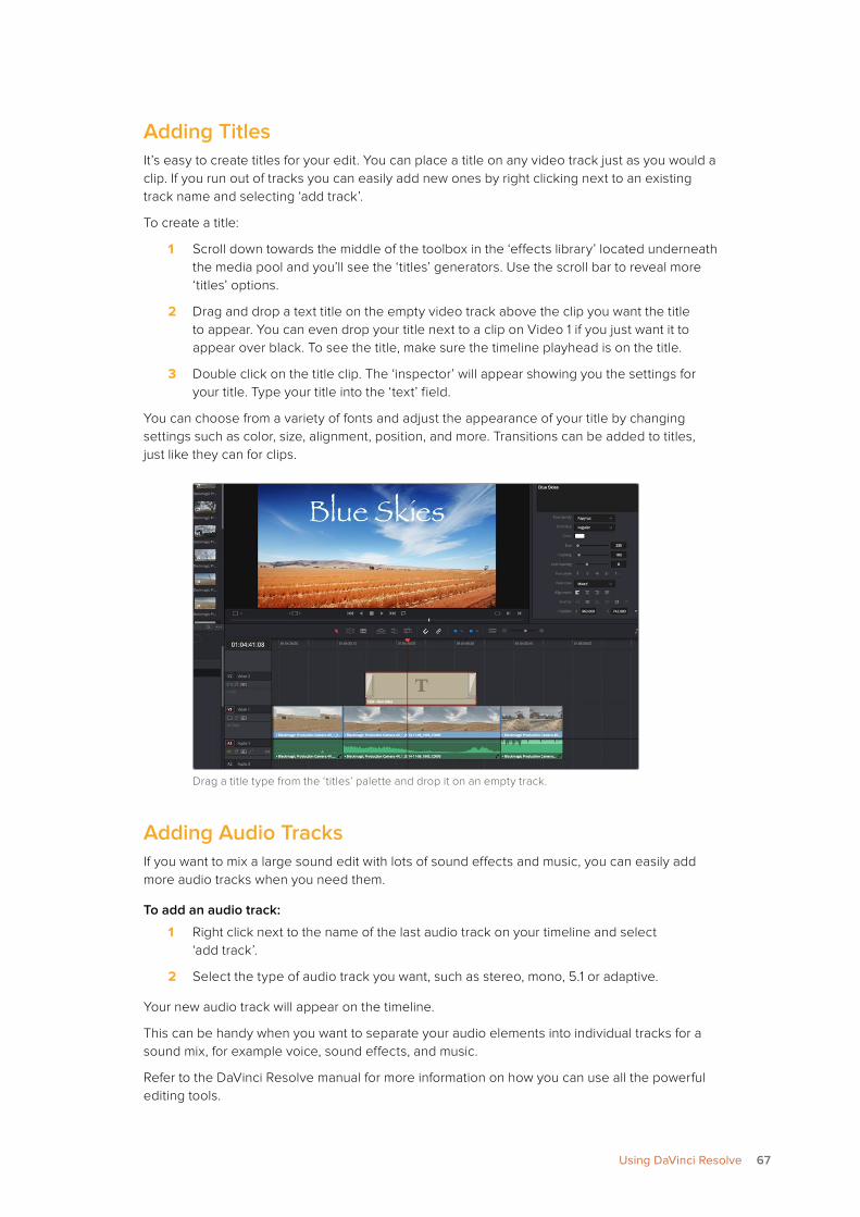
Adding TitlesIt’s easy to create titles for your edit. You can place a title on any video track just as you would a clip. If you run out of tracks you can easily add new ones by right clicking next to an existing track name and selecting ‘add track’.
To create a title:
1 Scroll down towards the middle of the toolbox in the ‘effects library’ located underneath the media pool and you’ll see the ‘titles’ generators. Use the scroll bar to reveal more ‘titles’ options.
2 Drag and drop a text title on the empty video track above the clip you want the title to appear. You can even drop your title next to a clip on Video 1 if you just want it to appear over black. To see the title, make sure the timeline playhead is on the title.
3 Double click on the title clip. The ‘inspector’ will appear showing you the settings for your title. Type your title into the ‘text’ field.
You can choose from a variety of fonts and adjust the appearance of your title by changing settings such as color, size, alignment, position, and more. Transitions can be added to titles, just like they can for clips.
Drag a title type from the ‘titles’ palette and drop it on an empty track.
Adding Audio TracksIf you want to mix a large sound edit with lots of sound effects and music, you can easily add more audio tracks when you need them.
To add an audio track:
1 Right click next to the name of the last audio track on your timeline and select ‘add track’.
2 Select the type of audio track you want, such as stereo, mono, 5.1 or adaptive.
Your new audio track will appear on the timeline.
This can be handy when you want to separate your audio elements into individual tracks for a sound mix, for example voice, sound effects, and music.
Refer to the DaVinci Resolve manual for more information on how you can use all the powerful editing tools.
67Using DaVinci Resolve
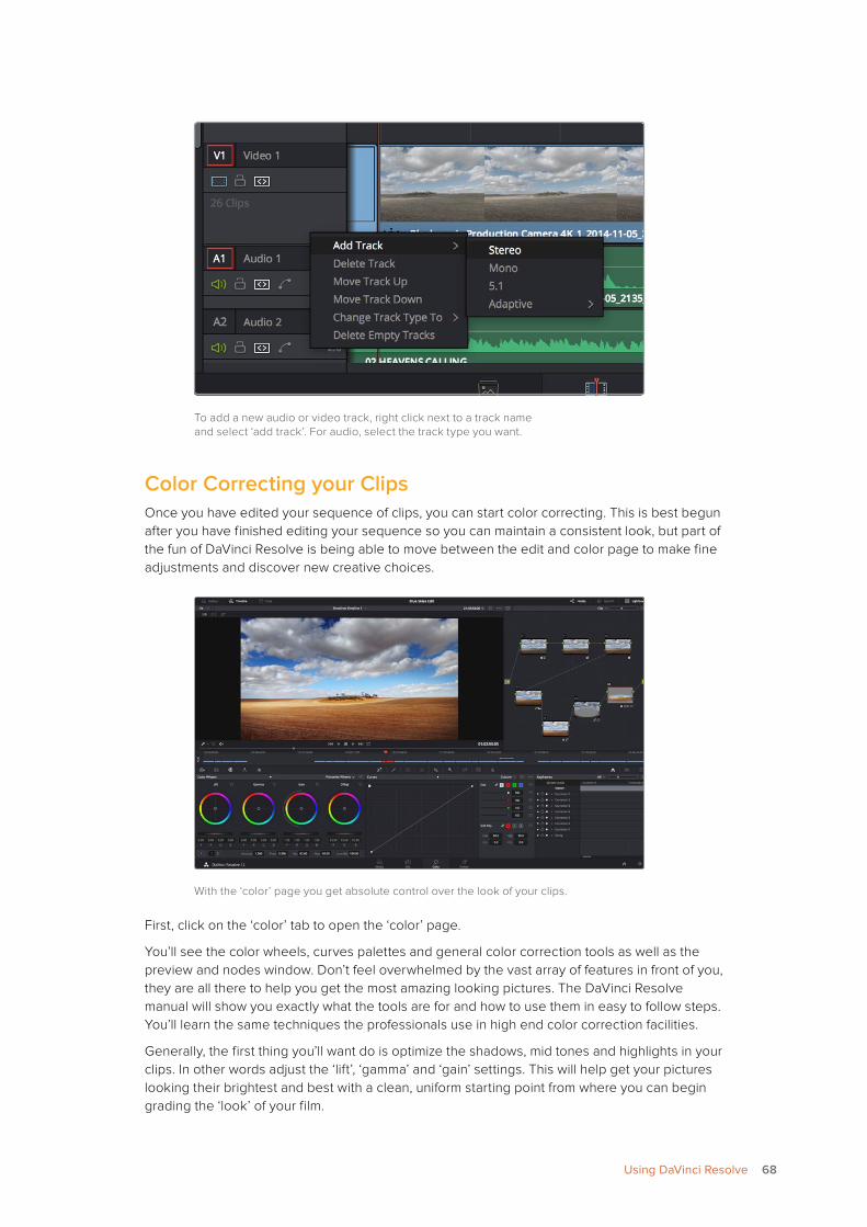
To add a new audio or video track, right click next to a track name and select ‘add track’. For audio, select the track type you want.
Color Correcting your Clips Once you have edited your sequence of clips, you can start color correcting. This is best begun after you have finished editing your sequence so you can maintain a consistent look, but part of the fun of DaVinci Resolve is being able to move between the edit and color page to make fine adjustments and discover new creative choices.
With the ‘color’ page you get absolute control over the look of your clips.
First, click on the ‘color’ tab to open the ‘color’ page.
You’ll see the color wheels, curves palettes and general color correction tools as well as the preview and nodes window. Don’t feel overwhelmed by the vast array of features in front of you, they are all there to help you get the most amazing looking pictures. The DaVinci Resolve manual will show you exactly what the tools are for and how to use them in easy to follow steps. You’ll learn the same techniques the professionals use in high end color correction facilities.
Generally, the first thing you’ll want do is optimize the shadows, mid tones and highlights in your clips. In other words adjust the ‘lift’, ‘gamma’ and ‘gain’ settings. This will help get your pictures looking their brightest and best with a clean, uniform starting point from where you can begin grading the ‘look’ of your film.
68Using DaVinci Resolve
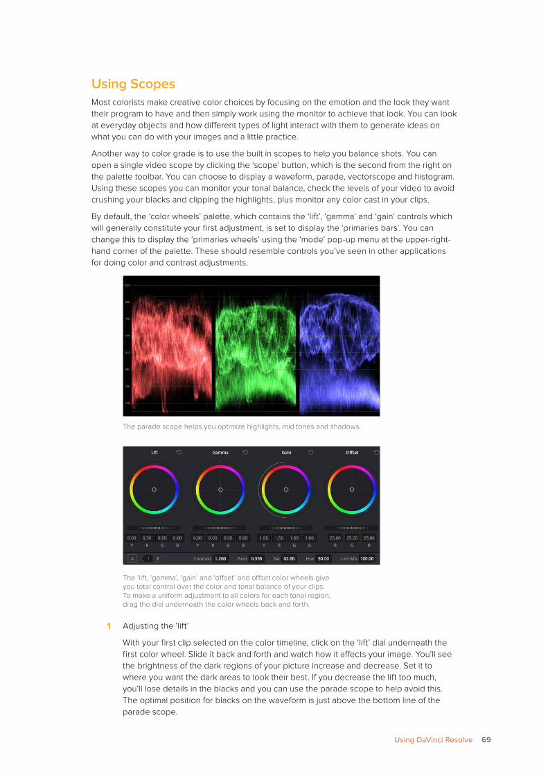
Using Scopes Most colorists make creative color choices by focusing on the emotion and the look they want their program to have and then simply work using the monitor to achieve that look. You can look at everyday objects and how different types of light interact with them to generate ideas on what you can do with your images and a little practice.
Another way to color grade is to use the built in scopes to help you balance shots. You can open a single video scope by clicking the ‘scope’ button, which is the second from the right on the palette toolbar. You can choose to display a waveform, parade, vectorscope and histogram. Using these scopes you can monitor your tonal balance, check the levels of your video to avoid crushing your blacks and clipping the highlights, plus monitor any color cast in your clips.
By default, the ‘color wheels’ palette, which contains the ‘lift’, ‘gamma’ and ‘gain’ controls which will generally constitute your first adjustment, is set to display the ‘primaries bars’. You can change this to display the ‘primaries wheels’ using the ‘mode’ pop-up menu at the upper-right-hand corner of the palette. These should resemble controls you’ve seen in other applications for doing color and contrast adjustments.
The parade scope helps you optimize highlights, mid tones and shadows.
The ‘lift, ‘gamma’, ‘gain’ and ‘offset’ and offset color wheels give you total control over the color and tonal balance of your clips. To make a uniform adjustment to all colors for each tonal region, drag the dial underneath the color wheels back and forth.
1 Adjusting the ‘lift’
With your first clip selected on the color timeline, click on the ‘lift’ dial underneath the first color wheel. Slide it back and forth and watch how it affects your image. You’ll see the brightness of the dark regions of your picture increase and decrease. Set it to where you want the dark areas to look their best. If you decrease the lift too much, you’ll lose details in the blacks and you can use the parade scope to help avoid this. The optimal position for blacks on the waveform is just above the bottom line of the parade scope.
69Using DaVinci Resolve
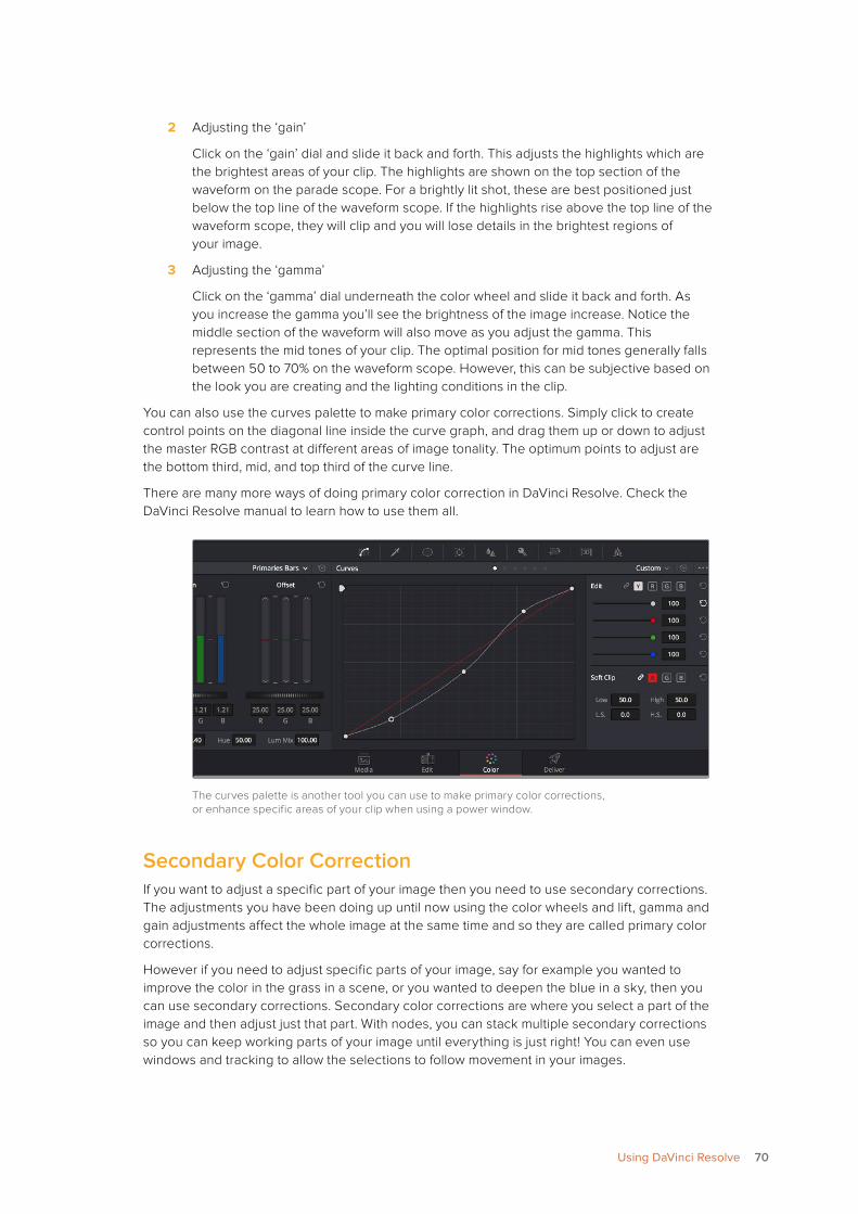
2 Adjusting the ‘gain’
Click on the ‘gain’ dial and slide it back and forth. This adjusts the highlights which are the brightest areas of your clip. The highlights are shown on the top section of the waveform on the parade scope. For a brightly lit shot, these are best positioned just below the top line of the waveform scope. If the highlights rise above the top line of the waveform scope, they will clip and you will lose details in the brightest regions of your image.
3 Adjusting the ‘gamma’
Click on the ‘gamma’ dial underneath the color wheel and slide it back and forth. As you increase the gamma you’ll see the brightness of the image increase. Notice the middle section of the waveform will also move as you adjust the gamma. This represents the mid tones of your clip. The optimal position for mid tones generally falls between 50 to 70% on the waveform scope. However, this can be subjective based on the look you are creating and the lighting conditions in the clip.
You can also use the curves palette to make primary color corrections. Simply click to create control points on the diagonal line inside the curve graph, and drag them up or down to adjust the master RGB contrast at different areas of image tonality. The optimum points to adjust are the bottom third, mid, and top third of the curve line.
There are many more ways of doing primary color correction in DaVinci Resolve. Check the DaVinci Resolve manual to learn how to use them all.
The curves palette is another tool you can use to make primary color corrections, or enhance specific areas of your clip when using a power window.
Secondary Color CorrectionIf you want to adjust a specific part of your image then you need to use secondary corrections. The adjustments you have been doing up until now using the color wheels and lift, gamma and gain adjustments affect the whole image at the same time and so they are called primary color corrections.
However if you need to adjust specific parts of your image, say for example you wanted to improve the color in the grass in a scene, or you wanted to deepen the blue in a sky, then you can use secondary corrections. Secondary color corrections are where you select a part of the image and then adjust just that part. With nodes, you can stack multiple secondary corrections so you can keep working parts of your image until everything is just right! You can even use windows and tracking to allow the selections to follow movement in your images.
70Using DaVinci Resolve
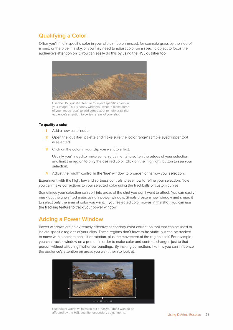
Qualifying a ColorOften you’ll find a specific color in your clip can be enhanced, for example grass by the side of a road, or the blue in a sky, or you may need to adjust color on a specific object to focus the audience’s attention on it. You can easily do this by using the HSL qualifier tool.
Use the HSL qualifier feature to select specific colors in your image. This is handy when you want to make areas of your image ‘pop’, to add contrast, or to help draw the audience’s attention to certain areas of your shot.
To qualify a color:
1 Add a new serial node.
2 Open the ‘qualifier’ palette and make sure the ‘color range’ sample eyedropper tool is selected.
3 Click on the color in your clip you want to affect.
Usually you’ll need to make some adjustments to soften the edges of your selection and limit the region to only the desired color. Click on the ‘highlight’ button to see your selection.
4 Adjust the ‘width’ control in the ‘hue’ window to broaden or narrow your selection.
Experiment with the high, low and softness controls to see how to refine your selection. Now you can make corrections to your selected color using the trackballs or custom curves.
Sometimes your selection can spill into areas of the shot you don’t want to affect. You can easily mask out the unwanted areas using a power window. Simply create a new window and shape it to select only the area of color you want. If your selected color moves in the shot, you can use the tracking feature to track your power window.
Adding a Power WindowPower windows are an extremely effective secondary color correction tool that can be used to isolate specific regions of your clips. These regions don’t have to be static, but can be tracked to move with a camera pan, tilt or rotation, plus the movement of the region itself. For example, you can track a window on a person in order to make color and contrast changes just to that person without affecting his/her surroundings. By making corrections like this you can influence the audience’s attention on areas you want them to look at.
Use power windows to mask out areas you don’t want to be affected by the HSL qualifier secondary adjustments.
71Using DaVinci Resolve
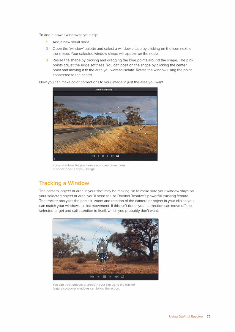
To add a power window to your clip:
1 Add a new serial node.
2 Open the ‘window’ palette and select a window shape by clicking on the icon next to the shape. Your selected window shape will appear on the node.
3 Resize the shape by clicking and dragging the blue points around the shape. The pink points adjust the edge softness. You can position the shape by clicking the center point and moving it to the area you want to isolate. Rotate the window using the point connected to the center.
Now you can make color corrections to your image in just the area you want.
Power windows let you make secondary corrections to specific parts of your image.
Tracking a WindowThe camera, object or area in your shot may be moving, so to make sure your window stays on your selected object or area, you’ll need to use DaVinci Resolve’s powerful tracking feature. The tracker analyzes the pan, tilt, zoom and rotation of the camera or object in your clip so you can match your windows to that movement. If this isn’t done, your correction can move off the selected target and call attention to itself, which you probably don’t want.
You can track objects or areas in your clip using the tracker feature so power windows can follow the action.
72Using DaVinci Resolve
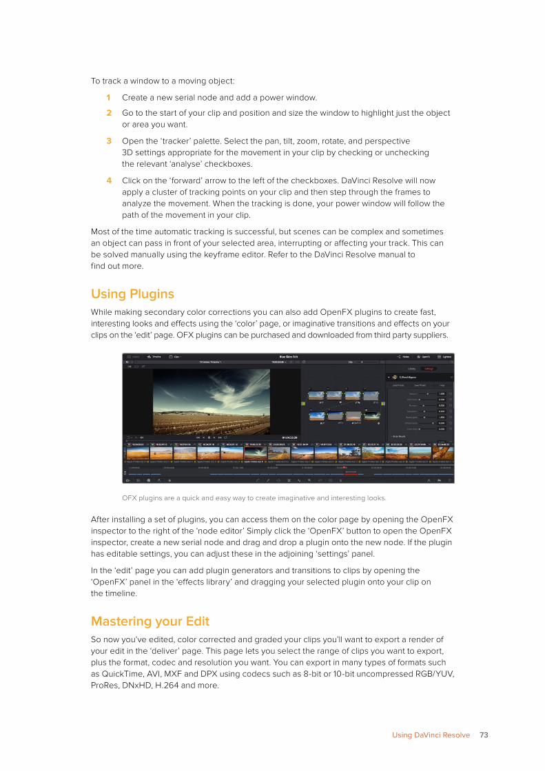
To track a window to a moving object:
1 Create a new serial node and add a power window.
2 Go to the start of your clip and position and size the window to highlight just the object or area you want.
3 Open the ‘tracker’ palette. Select the pan, tilt, zoom, rotate, and perspective 3D settings appropriate for the movement in your clip by checking or unchecking the relevant ‘analyse’ checkboxes.
4 Click on the ‘forward’ arrow to the left of the checkboxes. DaVinci Resolve will now apply a cluster of tracking points on your clip and then step through the frames to analyze the movement. When the tracking is done, your power window will follow the path of the movement in your clip.
Most of the time automatic tracking is successful, but scenes can be complex and sometimes an object can pass in front of your selected area, interrupting or affecting your track. This can be solved manually using the keyframe editor. Refer to the DaVinci Resolve manual to find out more.
Using PluginsWhile making secondary color corrections you can also add OpenFX plugins to create fast, interesting looks and effects using the ‘color’ page, or imaginative transitions and effects on your clips on the ‘edit’ page. OFX plugins can be purchased and downloaded from third party suppliers.
OFX plugins are a quick and easy way to create imaginative and interesting looks.
After installing a set of plugins, you can access them on the color page by opening the OpenFX inspector to the right of the ‘node editor’ Simply click the ‘OpenFX’ button to open the OpenFX inspector, create a new serial node and drag and drop a plugin onto the new node. If the plugin has editable settings, you can adjust these in the adjoining ‘settings’ panel.
In the ‘edit’ page you can add plugin generators and transitions to clips by opening the ‘OpenFX’ panel in the ‘effects library’ and dragging your selected plugin onto your clip on the timeline.
Mastering your EditSo now you’ve edited, color corrected and graded your clips you’ll want to export a render of your edit in the ‘deliver’ page. This page lets you select the range of clips you want to export, plus the format, codec and resolution you want. You can export in many types of formats such as QuickTime, AVI, MXF and DPX using codecs such as 8-bit or 10-bit uncompressed RGB/YUV, ProRes, DNxHD, H.264 and more.
73Using DaVinci Resolve
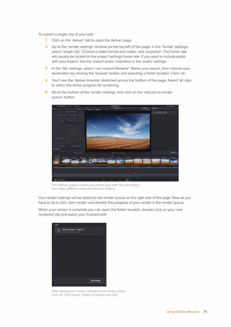
To export a single clip of your edit:
1 Click on the ‘deliver’ tab to open the deliver page.
2 Go to the ‘render settings’ window on the top left of the page. In the ‘format’ settings, select ‘single clip’. Choose a video format and codec, and resolution. The frame rate will usually be locked to the project settings frame rate. If you want to include audio with your export, tick the ‘export audio’ checkbox in the ‘audio’ settings.
3 In the ‘file’ settings, select ‘use custom filename’. Name your export, then choose your destination by clicking the ‘browse’ button and selecting a folder location. Click ‘ok’.
4 You’ll see the ‘deliver timeline’ stretched across the bottom of the page. Select ‘all clips’ to select the entire program for rendering.
5 Go to the bottom of the ‘render settings’ and click on the ‘add job to render queue’ button.
The ‘deliver’ page is where you export your edit. You can select from many different video formats and codecs
Your render settings will be added to the render queue on the right side of the page. Now all you have to do is click ‘start render’ and monitor the progress of your render in the render queue.
When your render is complete you can open the folder location, double click on your new rendered clip and watch your finished edit.
After adding your render settings to the render queue, click the ‘start render’ button to export your edit.
74Using DaVinci Resolve
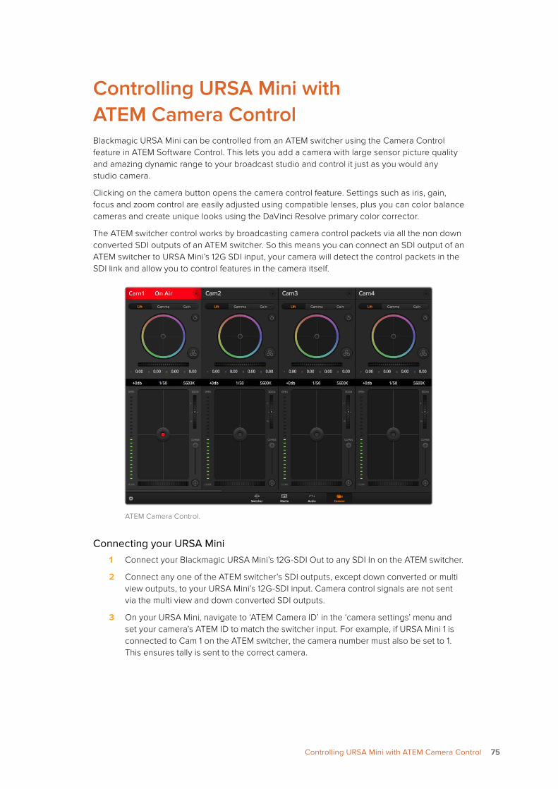
Controlling URSA Mini with ATEM Camera ControlBlackmagic URSA Mini can be controlled from an ATEM switcher using the Camera Control feature in ATEM Software Control. This lets you add a camera with large sensor picture quality and amazing dynamic range to your broadcast studio and control it just as you would any studio camera.
Clicking on the camera button opens the camera control feature. Settings such as iris, gain, focus and zoom control are easily adjusted using compatible lenses, plus you can color balance cameras and create unique looks using the DaVinci Resolve primary color corrector.
The ATEM switcher control works by broadcasting camera control packets via all the non down converted SDI outputs of an ATEM switcher. So this means you can connect an SDI output of an ATEM switcher to URSA Mini’s 12G SDI input, your camera will detect the control packets in the SDI link and allow you to control features in the camera itself.
ATEM Camera Control.
Connecting your URSA Mini1 Connect your Blackmagic URSA Mini’s 12G-SDI Out to any SDI In on the ATEM switcher.
2 Connect any one of the ATEM switcher’s SDI outputs, except down converted or multi view outputs, to your URSA Mini’s 12G-SDI input. Camera control signals are not sent via the multi view and down converted SDI outputs.
3 On your URSA Mini, navigate to ‘ATEM Camera ID’ in the ‘camera settings’ menu and set your camera’s ATEM ID to match the switcher input. For example, if URSA Mini 1 is connected to Cam 1 on the ATEM switcher, the camera number must also be set to 1. This ensures tally is sent to the correct camera.
7575Controlling URSA Mini with ATEM Camera Control
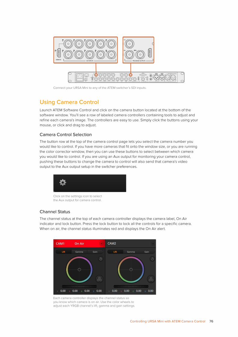
Connect your URSA Mini to any of the ATEM switcher’s SDI inputs.
Using Camera ControlLaunch ATEM Software Control and click on the camera button located at the bottom of the software window. You’ll see a row of labeled camera controllers containing tools to adjust and refine each camera’s image. The controllers are easy to use. Simply click the buttons using your mouse, or click and drag to adjust.
Camera Control SelectionThe button row at the top of the camera control page lets you select the camera number you would like to control. If you have more cameras that fit onto the window size, or you are running the color corrector window, then you can use these buttons to select between which camera you would like to control. If you are using an Aux output for monitoring your camera control, pushing these buttons to change the camera to control will also send that camera’s video output to the Aux output setup in the switcher preferences.
Click on the settings icon to select the Aux output for camera control.
Channel StatusThe channel status at the top of each camera controller displays the camera label, On Air indicator and lock button. Press the lock button to lock all the controls for a specific camera. When on air, the channel status illuminates red and displays the On Air alert.
Each camera controller displays the channel status so you know which camera is on air. Use the color wheels to adjust each YRGB channel’s lift, gamma and gain settings.
PUSH PUSH
CONTROL
USB 2.0 HDMI INSDI INPUTS REF IN AUX 1-3 PREVIEW PROGRAM OUTPUTS MULTI-VIEW ANALOG AUDIO IN
STEREO IN
REMOTE
ANALOG AUDIO OUT
CH 1
All SDI and HDMI video connections areSD, HD and Ultra HD switchable unless indicated
CH 2CH 1 CH 2
IN1
IN2
IN1
IN3
IN4
IN5
IN6
IN7
IN8
IN9
IN10
2
1 3
2
1
HD HD HD
7676Controlling URSA Mini with ATEM Camera Control
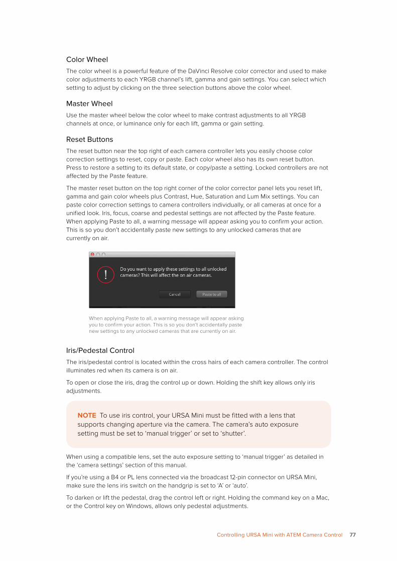
Color WheelThe color wheel is a powerful feature of the DaVinci Resolve color corrector and used to make color adjustments to each YRGB channel’s lift, gamma and gain settings. You can select which setting to adjust by clicking on the three selection buttons above the color wheel.
Master WheelUse the master wheel below the color wheel to make contrast adjustments to all YRGB channels at once, or luminance only for each lift, gamma or gain setting.
Reset ButtonsThe reset button near the top right of each camera controller lets you easily choose color correction settings to reset, copy or paste. Each color wheel also has its own reset button. Press to restore a setting to its default state, or copy/paste a setting. Locked controllers are not affected by the Paste feature.
The master reset button on the top right corner of the color corrector panel lets you reset lift, gamma and gain color wheels plus Contrast, Hue, Saturation and Lum Mix settings. You can paste color correction settings to camera controllers individually, or all cameras at once for a unified look. Iris, focus, coarse and pedestal settings are not affected by the Paste feature. When applying Paste to all, a warning message will appear asking you to confirm your action. This is so you don’t accidentally paste new settings to any unlocked cameras that are currently on air.
When applying Paste to all, a warning message will appear asking you to confirm your action. This is so you don’t accidentally paste new settings to any unlocked cameras that are currently on air.
Iris/Pedestal ControlThe iris/pedestal control is located within the cross hairs of each camera controller. The control illuminates red when its camera is on air.
To open or close the iris, drag the control up or down. Holding the shift key allows only iris adjustments.
When using a compatible lens, set the auto exposure setting to ‘manual trigger’ as detailed in the ‘camera settings’ section of this manual.
If you’re using a B4 or PL lens connected via the broadcast 12-pin connector on URSA Mini, make sure the lens iris switch on the handgrip is set to ‘A’ or ‘auto’.
To darken or lift the pedestal, drag the control left or right. Holding the command key on a Mac, or the Control key on Windows, allows only pedestal adjustments.
NOTE To use iris control, your URSA Mini must be fitted with a lens that supports changing aperture via the camera. The camera’s auto exposure setting must be set to ‘manual trigger’ or set to ‘shutter’.
7777Controlling URSA Mini with ATEM Camera Control
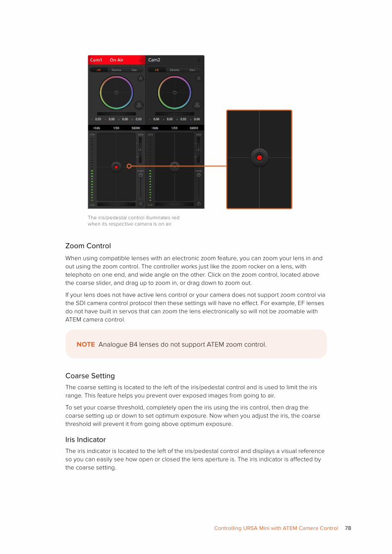
The iris/pedestal control illuminates red when its respective camera is on air.
Zoom Control
When using compatible lenses with an electronic zoom feature, you can zoom your lens in and out using the zoom control. The controller works just like the zoom rocker on a lens, with telephoto on one end, and wide angle on the other. Click on the zoom control, located above the coarse slider, and drag up to zoom in, or drag down to zoom out.
If your lens does not have active lens control or your camera does not support zoom control via the SDI camera control protocol then these settings will have no effect. For example, EF lenses do not have built in servos that can zoom the lens electronically so will not be zoomable with ATEM camera control.
Coarse SettingThe coarse setting is located to the left of the iris/pedestal control and is used to limit the iris range. This feature helps you prevent over exposed images from going to air.
To set your coarse threshold, completely open the iris using the iris control, then drag the coarse setting up or down to set optimum exposure. Now when you adjust the iris, the coarse threshold will prevent it from going above optimum exposure.
Iris IndicatorThe iris indicator is located to the left of the iris/pedestal control and displays a visual reference so you can easily see how open or closed the lens aperture is. The iris indicator is affected by the coarse setting.
NOTE Analogue B4 lenses do not support ATEM zoom control.
7878Controlling URSA Mini with ATEM Camera Control
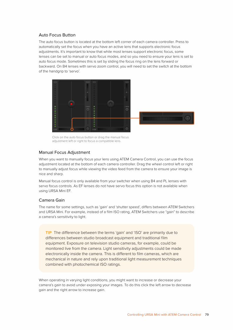
Auto Focus ButtonThe auto focus button is located at the bottom left corner of each camera controller. Press to automatically set the focus when you have an active lens that supports electronic focus adjustments. It’s important to know that while most lenses support electronic focus, some lenses can be set to manual or auto focus modes, and so you need to ensure your lens is set to auto focus mode. Sometimes this is set by sliding the focus ring on the lens forward or backward. On B4 lenses with servo zoom control, you will need to set the switch at the bottom of the handgrip to ‘servo’.
Click on the auto focus button or drag the manual focus adjustment left or right to focus a compatible lens.
Manual Focus AdjustmentWhen you want to manually focus your lens using ATEM Camera Control, you can use the focus adjustment located at the bottom of each camera controller. Drag the wheel control left or right to manually adjust focus while viewing the video feed from the camera to ensure your image is nice and sharp.
Manual focus control is only available from your switcher when using B4 and PL lenses with servo focus controls. As EF lenses do not have servo focus this option is not available when using URSA Mini EF.
Camera GainThe name for some settings, such as ‘gain’ and ‘shutter speed’, differs between ATEM Switchers and URSA Mini. For example, instead of a film ISO rating, ATEM Switchers use “gain” to describe a camera’s sensitivity to light.
When operating in varying light conditions, you might want to increase or decrease your camera’s gain to avoid under exposing your images. To do this click the left arrow to decrease gain and the right arrow to increase gain.
TIP The difference between the terms ‘gain’ and ‘ISO’ are primarily due to differences between studio broadcast equipment and traditional film equipment. Exposure on television studio cameras, for example, could be monitored live from the camera. Light sensitivity adjustments could be made electronically inside the camera. This is different to film cameras, which are mechanical in nature and rely upon traditional light measurement techniques combined with photochemical ISO ratings.
7979Controlling URSA Mini with ATEM Camera Control
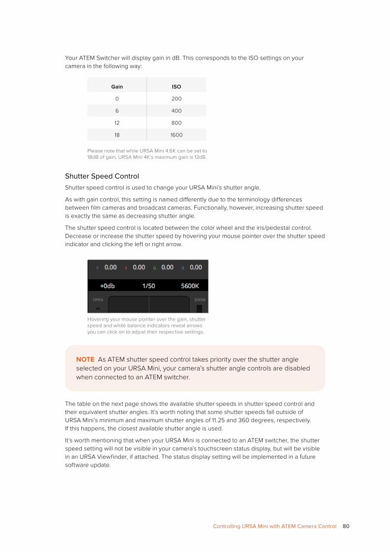
Your ATEM Switcher will display gain in dB. This corresponds to the ISO settings on your camera in the following way:
Gain ISO
0 200
6 400
12 800
18 1600
Please note that while URSA Mini 4.6K can be set to 18dB of gain, URSA Mini 4K’s maximum gain is 12dB.
Shutter Speed ControlShutter speed control is used to change your URSA Mini’s shutter angle.
As with gain control, this setting is named differently due to the terminology differences between film cameras and broadcast cameras. Functionally, however, increasing shutter speed is exactly the same as decreasing shutter angle.
The shutter speed control is located between the color wheel and the iris/pedestal control. Decrease or increase the shutter speed by hovering your mouse pointer over the shutter speed indicator and clicking the left or right arrow.
Hovering your mouse pointer over the gain, shutter speed and white balance indicators reveal arrows you can click on to adjust their respective settings.
The table on the next page shows the available shutter speeds in shutter speed control and their equivalent shutter angles. It’s worth noting that some shutter speeds fall outside of URSA Mini’s minimum and maximum shutter angles of 11.25 and 360 degrees, respectively. If this happens, the closest available shutter angle is used.
It’s worth mentioning that when your URSA Mini is connected to an ATEM switcher, the shutter speed setting will not be visible in your camera’s touchscreen status display, but will be visible in an URSA Viewfinder, if attached. The status display setting will be implemented in a future software update.
NOTE As ATEM shutter speed control takes priority over the shutter angle selected on your URSA Mini, your camera’s shutter angle controls are disabled when connected to an ATEM switcher.
8080Controlling URSA Mini with ATEM Camera Control
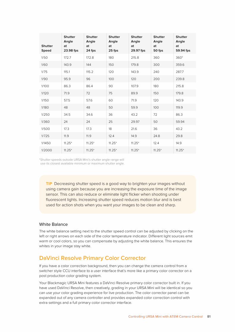
Shutter Speed
Shutter Angle at 23.98 fps
Shutter Angle at 24 fps
Shutter Angle at 25 fps
Shutter Angle at 29.97 fps
Shutter Angle at 50 fps
Shutter Angle at 59.94 fps
1/50 172.7 172.8 180 215.8 360 360*
1/60 143.9 144 150 179.8 300 359.6
1/75 115.1 115.2 120 143.9 240 287.7
1/90 95.9 96 100 120 200 239.8
1/100 86.3 86.4 90 107.9 180 215.8
1/120 71.9 72 75 89.9 150 179.8
1/150 57.5 57.6 60 71.9 120 143.9
1/180 48 48 50 59.9 100 119.9
1/250 34.5 34.6 36 43.2 72 86.3
1/360 24 24 25 29.97 50 59.94
1/500 17.3 17.3 18 21.6 36 43.2
1/725 11.9 11.9 12.4 14.9 24.8 29.8
1/1450 11.25* 11.25* 11.25* 11.25* 12.4 14.9
1/2000 11.25* 11.25* 11.25* 11.25* 11.25* 11.25*
* Shutter speeds outside URSA Mini’s shutter angle range will use its closest available minimum or maximum shutter angle.
White BalanceThe white balance setting next to the shutter speed control can be adjusted by clicking on the left or right arrows on each side of the color temperature indicator. Different light sources emit warm or cool colors, so you can compensate by adjusting the white balance. This ensures the whites in your image stay white.
DaVinci Resolve Primary Color CorrectorIf you have a color correction background, then you can change the camera control from a switcher style CCU interface to a user interface that’s more like a primary color corrector on a post production color grading system.
Your Blackmagic URSA Mini features a DaVinci Resolve primary color corrector built in. If you have used DaVinci Resolve, then creatively, grading in your URSA Mini will be identical so you can use your color grading experience for live production. The color corrector panel can be expanded out of any camera controller and provides expanded color correction control with extra settings and a full primary color corrector interface.
TIP Decreasing shutter speed is a good way to brighten your images without using camera gain because you are increasing the exposure time of the image sensor. This can also reduce or eliminate light flicker when shooting under fluorescent lights. Increasing shutter speed reduces motion blur and is best used for action shots when you want your images to be clean and sharp.
8181Controlling URSA Mini with ATEM Camera Control
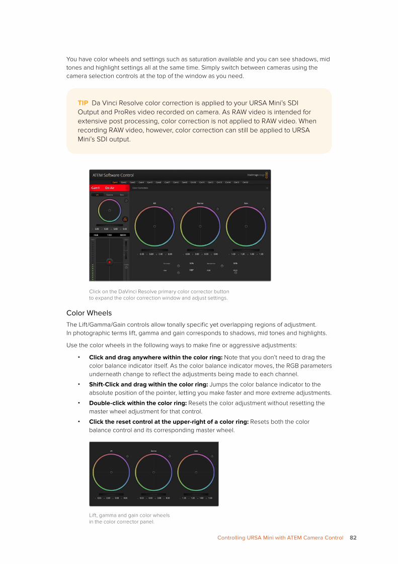
You have color wheels and settings such as saturation available and you can see shadows, mid tones and highlight settings all at the same time. Simply switch between cameras using the camera selection controls at the top of the window as you need.
Click on the DaVinci Resolve primary color corrector button to expand the color correction window and adjust settings.
Color WheelsThe Lift/Gamma/Gain controls allow tonally specific yet overlapping regions of adjustment. In photographic terms lift, gamma and gain corresponds to shadows, mid tones and highlights.
Use the color wheels in the following ways to make fine or aggressive adjustments:
� Click and drag anywhere within the color ring: Note that you don’t need to drag the color balance indicator itself. As the color balance indicator moves, the RGB parameters underneath change to reflect the adjustments being made to each channel.
� Shift-Click and drag within the color ring: Jumps the color balance indicator to the absolute position of the pointer, letting you make faster and more extreme adjustments.
� Double-click within the color ring: Resets the color adjustment without resetting the master wheel adjustment for that control.
� Click the reset control at the upper-right of a color ring: Resets both the color balance control and its corresponding master wheel.
Lift, gamma and gain color wheels in the color corrector panel.
TIP Da Vinci Resolve color correction is applied to your URSA Mini’s SDI Output and ProRes video recorded on camera. As RAW video is intended for extensive post processing, color correction is not applied to RAW video. When recording RAW video, however, color correction can still be applied to URSA Mini’s SDI output.
8282Controlling URSA Mini with ATEM Camera Control
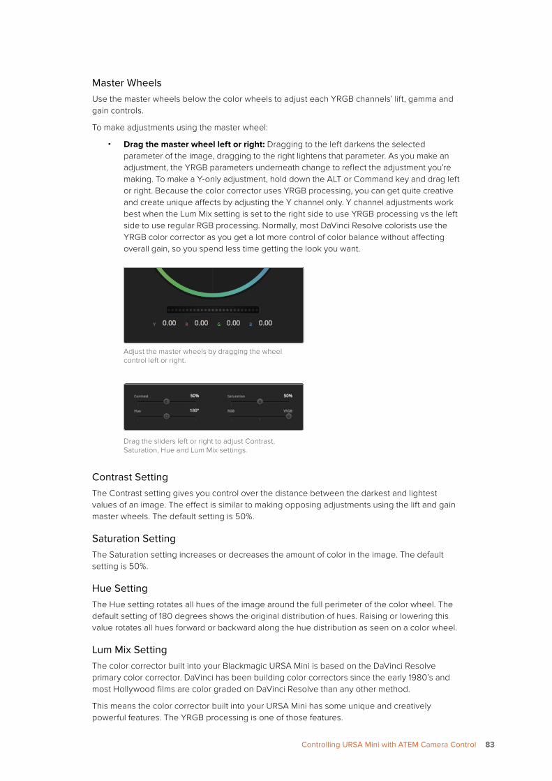
Master WheelsUse the master wheels below the color wheels to adjust each YRGB channels’ lift, gamma and gain controls.
To make adjustments using the master wheel:
� Drag the master wheel left or right: Dragging to the left darkens the selected parameter of the image, dragging to the right lightens that parameter. As you make an adjustment, the YRGB parameters underneath change to reflect the adjustment you’re making. To make a Y-only adjustment, hold down the ALT or Command key and drag left or right. Because the color corrector uses YRGB processing, you can get quite creative and create unique affects by adjusting the Y channel only. Y channel adjustments work best when the Lum Mix setting is set to the right side to use YRGB processing vs the left side to use regular RGB processing. Normally, most DaVinci Resolve colorists use the YRGB color corrector as you get a lot more control of color balance without affecting overall gain, so you spend less time getting the look you want.
Adjust the master wheels by dragging the wheel control left or right.
Drag the sliders left or right to adjust Contrast, Saturation, Hue and Lum Mix settings.
Contrast SettingThe Contrast setting gives you control over the distance between the darkest and lightest values of an image. The effect is similar to making opposing adjustments using the lift and gain master wheels. The default setting is 50%.
Saturation SettingThe Saturation setting increases or decreases the amount of color in the image. The default setting is 50%.
Hue SettingThe Hue setting rotates all hues of the image around the full perimeter of the color wheel. The default setting of 180 degrees shows the original distribution of hues. Raising or lowering this value rotates all hues forward or backward along the hue distribution as seen on a color wheel.
Lum Mix SettingThe color corrector built into your Blackmagic URSA Mini is based on the DaVinci Resolve primary color corrector. DaVinci has been building color correctors since the early 1980’s and most Hollywood films are color graded on DaVinci Resolve than any other method.
This means the color corrector built into your URSA Mini has some unique and creatively powerful features. The YRGB processing is one of those features.
8383Controlling URSA Mini with ATEM Camera Control
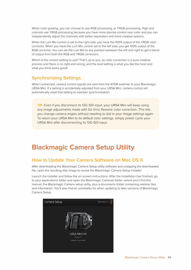
When color grading, you can choose to use RGB processing, or YRGB processing. High end colorists use YRGB processing because you have more precise control over color and you can independently adjust the channels with better separation and more creative options.
When the Lum Mix control is set to the right side, you have the 100% output of the YRGB color corrector. When you have the Lum Mix control set to the left side, you get 100% output of the RGB corrector. You can set the Lum Mix to any position between the left and right to get a blend of output from both the RGB and YRGB correctors.
Which is the correct setting to use? That’s up to you, as color correction is a pure creative process and there is no right and wrong, and the best setting is what you like the most and what you think looks good!
Synchronizing Settings When connected, camera control signals are sent from the ATEM switcher to your Blackmagic URSA Mini. If a setting is accidentally adjusted from your URSA Mini, camera control will automatically reset that setting to maintain synchronization.
Blackmagic Camera Setup Utility
How to Update Your Camera Software on Mac OS XAfter downloading the Blackmagic Camera Setup utility software and unzipping the downloaded file, open the resulting disk image to reveal the Blackmagic Camera Setup Installer.
Launch the installer and follow the on screen instructions. After the installation has finished, go to your applications folder and open the Blackmagic Cameras folder, where you’ll find this manual, the Blackmagic Camera setup utility, plus a documents folder containing readme files and information. You’ll also find an uninstaller for when updating to later versions of Blackmagic Camera Setup.
TIP Even if you disconnect its 12G-SDI input, your URSA Mini will keep using any image adjustments made with Da Vinci Resolve color correction. This lets you change camera angles without needing to dial in your image settings again. To return your URSA Mini to its default color settings, simply power cycle your URSA Mini after disconnecting its 12G-SDI input.
84Blackmagic Camera Setup Utility
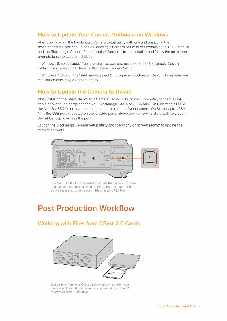
How to Update Your Camera Software on WindowsAfter downloading the Blackmagic Camera Setup utility software and unzipping the downloaded file, you should see a Blackmagic Camera Setup folder containing this PDF manual and the Blackmagic Camera Setup Installer. Double-click the installer and follow the on screen prompts to complete the installation.
In Windows 8, select ‘apps’ from the ‘start’ screen and navigate to the Blackmagic Design folder. From here you can launch Blackmagic Camera Setup.
In Windows 7, click on the ‘start’ menu, select ‘all programs>Blackmagic Design’. From here you can launch Blackmagic Camera Setup.
How to Update the Camera SoftwareAfter installing the latest Blackmagic Camera Setup utility on your computer, connect a USB cable between the computer and your Blackmagic URSA or URSA Mini. On Blackmagic URSA, the Mini-B USB 2.0 port is located on the bottom panel of your camera. On Blackmagic URSA Mini, the USB port is located on the left side panel above the memory card slots. Simply open the rubber cap to access the port.
Launch the Blackmagic Camera Setup utility and follow any on screen prompt to update the camera software.
The Mini-B USB 2.0 port is used to update the camera software and can be found on Blackmagic URSA’s bottom panel, and above the memory card slots on Blackmagic URSA Mini.
Post Production Workflow
Working with Files from CFast 2.0 Cards
Edit directly from your CFast card by removing it from your camera and mounting it on your computer using a CFast 2.0 reader/writer or CFast drive.
REC
ZOO
M
DISP
PGM
1 CFA
ST
IRIS
FOC
US
REC
IRIS
FOC
US
PE
AK
DIS
PM
EN
USL
ATE
2
IRIS
SDI O
UT
0 -6 -12
-18
-24
-30
-36
-42
-48
LR
SDI I
N
RE
F IN
TIM
EC
OD
E IN
TIM
EC
OD
E O
UT
12V
CH
1SO
LOC
H1
MU
TEC
H2
MU
TEC
H2
SOLO
FOC
US
PE
AK
DIS
PM
EN
USL
ATE
PUSH PUSHPUSH
REC
ZOOM
DISP
PGM
1
CFAST
IRIS
FOCUS
REC
IRIS
FOCUSPEAKDISPMENUSLATE
2
IRIS
SDI OUT
0
-6
-12
-18
-24
-30
-36
-42
-48
LR
SDI IN
REF IN
TIMECODE IN
TIMECODE OUT
12V
CH1SOLO
CH1MUTE
CH2MUTE
CH2SOLO
FOCUSPEAKDISPMENUSLATE
PU
SHP
USH
PU
SH
85Post Production Workflow
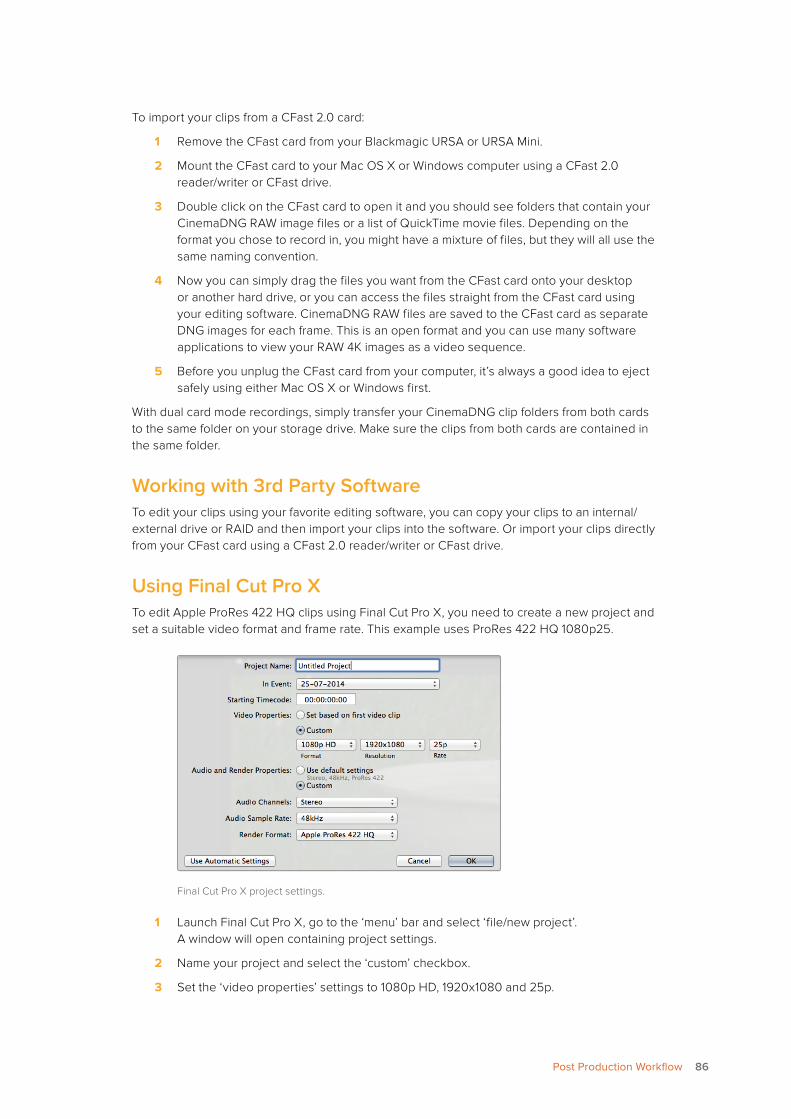
To import your clips from a CFast 2.0 card:
1 Remove the CFast card from your Blackmagic URSA or URSA Mini.
2 Mount the CFast card to your Mac OS X or Windows computer using a CFast 2.0 reader/writer or CFast drive.
3 Double click on the CFast card to open it and you should see folders that contain your CinemaDNG RAW image files or a list of QuickTime movie files. Depending on the format you chose to record in, you might have a mixture of files, but they will all use the same naming convention.
4 Now you can simply drag the files you want from the CFast card onto your desktop or another hard drive, or you can access the files straight from the CFast card using your editing software. CinemaDNG RAW files are saved to the CFast card as separate DNG images for each frame. This is an open format and you can use many software applications to view your RAW 4K images as a video sequence.
5 Before you unplug the CFast card from your computer, it’s always a good idea to eject safely using either Mac OS X or Windows first.
With dual card mode recordings, simply transfer your CinemaDNG clip folders from both cards to the same folder on your storage drive. Make sure the clips from both cards are contained in the same folder.
Working with 3rd Party SoftwareTo edit your clips using your favorite editing software, you can copy your clips to an internal/external drive or RAID and then import your clips into the software. Or import your clips directly from your CFast card using a CFast 2.0 reader/writer or CFast drive.
Using Final Cut Pro XTo edit Apple ProRes 422 HQ clips using Final Cut Pro X, you need to create a new project and set a suitable video format and frame rate. This example uses ProRes 422 HQ 1080p25.
Final Cut Pro X project settings.
1 Launch Final Cut Pro X, go to the ‘menu’ bar and select ‘file/new project’. A window will open containing project settings.
2 Name your project and select the ‘custom’ checkbox.
3 Set the ‘video properties’ settings to 1080p HD, 1920x1080 and 25p.
86Post Production Workflow
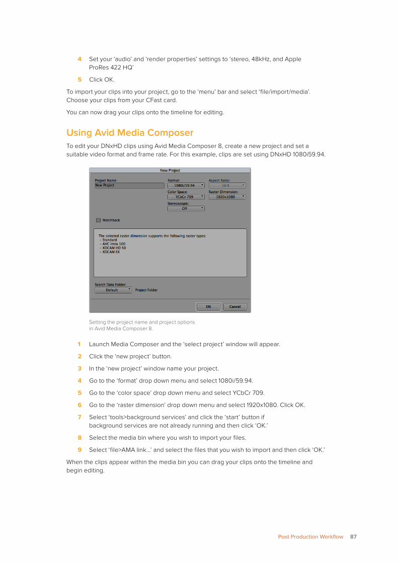
4 Set your ‘audio’ and ‘render properties’ settings to ‘stereo, 48kHz, and Apple ProRes 422 HQ’
5 Click OK.
To import your clips into your project, go to the ‘menu’ bar and select ‘file/import/media’. Choose your clips from your CFast card.
You can now drag your clips onto the timeline for editing.
Using Avid Media ComposerTo edit your DNxHD clips using Avid Media Composer 8, create a new project and set a suitable video format and frame rate. For this example, clips are set using DNxHD 1080i59.94.
Setting the project name and project options in Avid Media Composer 8.
1 Launch Media Composer and the ‘select project’ window will appear.
2 Click the ‘new project’ button.
3 In the ‘new project’ window name your project.
4 Go to the ‘format’ drop down menu and select 1080i/59.94.
5 Go to the ‘color space’ drop down menu and select YCbCr 709.
6 Go to the ‘raster dimension’ drop down menu and select 1920x1080. Click OK.
7 Select ‘tools>background services’ and click the ‘start’ button if background services are not already running and then click ‘OK.’
8 Select the media bin where you wish to import your files.
9 Select ‘file>AMA link...’ and select the files that you wish to import and then click ‘OK.’
When the clips appear within the media bin you can drag your clips onto the timeline and begin editing.
87Post Production Workflow
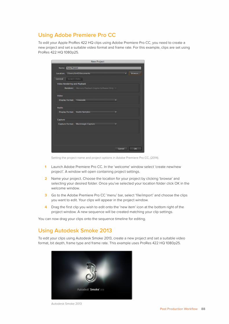
Using Adobe Premiere Pro CCTo edit your Apple ProRes 422 HQ clips using Adobe Premiere Pro CC, you need to create a new project and set a suitable video format and frame rate. For this example, clips are set using ProRes 422 HQ 1080p25.
Setting the project name and project options in Adobe Premiere Pro CC, (2014).
1 Launch Adobe Premiere Pro CC. In the ‘welcome’ window select ‘create new/new project’. A window will open containing project settings.
2 Name your project. Choose the location for your project by clicking ‘browse’ and selecting your desired folder. Once you’ve selected your location folder click OK in the welcome window.
3 Go to the Adobe Premiere Pro CC ‘menu’ bar, select ‘file/import’ and choose the clips you want to edit. Your clips will appear in the project window.
4 Drag the first clip you wish to edit onto the ‘new item’ icon at the bottom right of the project window. A new sequence will be created matching your clip settings.
You can now drag your clips onto the sequence timeline for editing.
Using Autodesk Smoke 2013To edit your clips using Autodesk Smoke 2013, create a new project and set a suitable video format, bit depth, frame type and frame rate. This example uses ProRes 422 HQ 1080p25.
Autodesk Smoke 2013
88Post Production Workflow
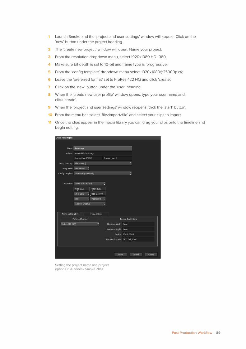
1 Launch Smoke and the ‘project and user settings’ window will appear. Click on the ‘new’ button under the project heading.
2 The ‘create new project’ window will open. Name your project.
3 From the resolution dropdown menu, select 1920x1080 HD 1080.
4 Make sure bit depth is set to 10-bit and frame type is ‘progressive’.
5 From the ‘config template’ dropdown menu select [email protected].
6 Leave the ‘preferred format’ set to ProRes 422 HQ and click ‘create’.
7 Click on the ‘new’ button under the ‘user’ heading.
8 When the ‘create new user profile’ window opens, type your user name and click ‘create’.
9 When the ‘project and user settings’ window reopens, click the ‘start’ button.
10 From the menu bar, select ‘file>import>file’ and select your clips to import.
11 Once the clips appear in the media library you can drag your clips onto the timeline and begin editing.
Setting the project name and project options in Autodesk Smoke 2013.
89Post Production Workflow
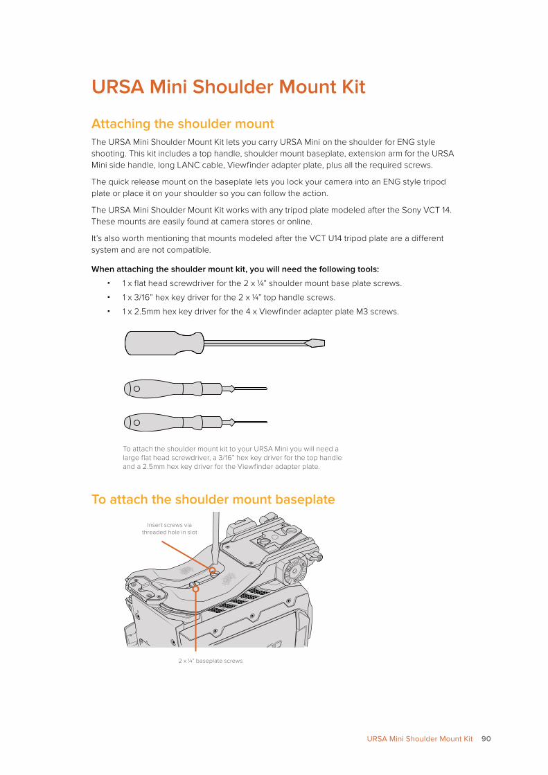
URSA Mini Shoulder Mount Kit
Attaching the shoulder mountThe URSA Mini Shoulder Mount Kit lets you carry URSA Mini on the shoulder for ENG style shooting. This kit includes a top handle, shoulder mount baseplate, extension arm for the URSA Mini side handle, long LANC cable, Viewfinder adapter plate, plus all the required screws.
The quick release mount on the baseplate lets you lock your camera into an ENG style tripod plate or place it on your shoulder so you can follow the action.
The URSA Mini Shoulder Mount Kit works with any tripod plate modeled after the Sony VCT 14. These mounts are easily found at camera stores or online.
It’s also worth mentioning that mounts modeled after the VCT U14 tripod plate are a different system and are not compatible.
When attaching the shoulder mount kit, you will need the following tools:
� 1 x flat head screwdriver for the 2 x ¼” shoulder mount base plate screws.
� 1 x 3/16” hex key driver for the 2 x ¼” top handle screws.
� 1 x 2.5mm hex key driver for the 4 x Viewfinder adapter plate M3 screws.
To attach the shoulder mount kit to your URSA Mini you will need a large flat head screwdriver, a 3/16” hex key driver for the top handle and a 2.5mm hex key driver for the Viewfinder adapter plate.
To attach the shoulder mount baseplate
Insert screws via threaded hole in slot
2 x ¼” baseplate screws
90URSA Mini Shoulder Mount Kit
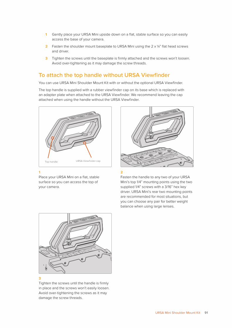
1 Gently place your URSA Mini upside down on a flat, stable surface so you can easily access the base of your camera.
2 Fasten the shoulder mount baseplate to URSA Mini using the 2 x ¼” flat head screws and driver.
3 Tighten the screws until the baseplate is firmly attached and the screws won’t loosen.Avoid over-tightening as it may damage the screw threads.
To attach the top handle without URSA ViewfinderYou can use URSA Mini Shoulder Mount Kit with or without the optional URSA Viewfinder.
The top handle is supplied with a rubber viewfinder cap on its base which is replaced with an adapter plate when attached to the URSA Viewfinder. We recommend leaving the cap attached when using the handle without the URSA Viewfinder.
Top handle URSA Viewfinder cap
1 Place your URSA Mini on a flat, stable surface so you can access the top of your camera.
2 Fasten the handle to any two of your URSA Mini’s top 1/4” mounting points using the two supplied 1/4” screws with a 3/16” hex key driver. URSA Mini’s rear two mounting points are recommended for most situations, but you can choose any pair for better weight balance when using large lenses.
3 Tighten the screws until the handle is firmly in place and the screws won’t easily loosen. Avoid over-tightening the screws as it may damage the screw threads.
91URSA Mini Shoulder Mount Kit
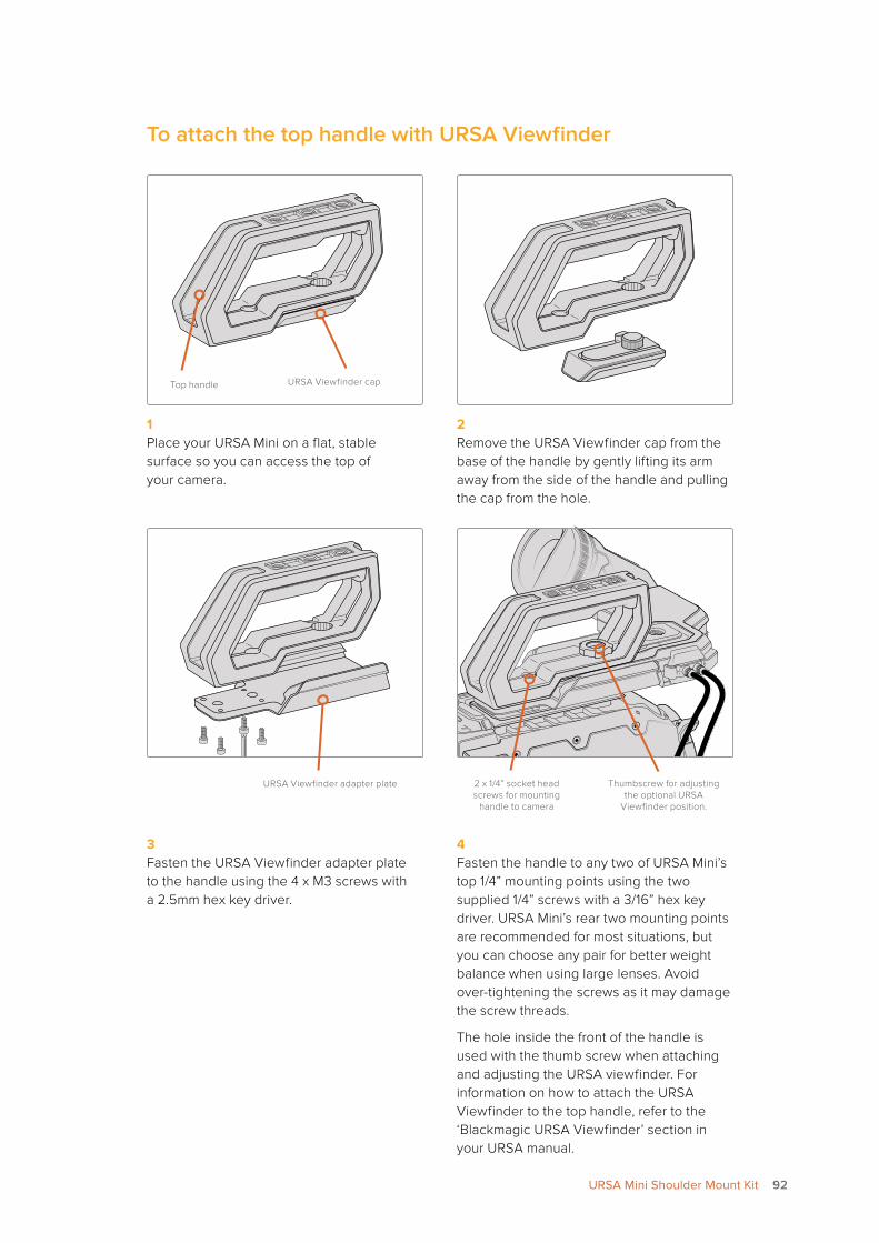
To attach the top handle with URSA Viewfinder
Top handle URSA Viewfinder cap
1 Place your URSA Mini on a flat, stable surface so you can access the top of your camera.
2 Remove the URSA Viewfinder cap from the base of the handle by gently lifting its arm away from the side of the handle and pulling the cap from the hole.
URSA Viewfinder adapter plate Thumbscrew for adjusting the optional URSA
Viewfinder position.
2 x 1/4” socket head screws for mounting
handle to camera
3 Fasten the URSA Viewfinder adapter plate to the handle using the 4 x M3 screws with a 2.5mm hex key driver.
4 Fasten the handle to any two of URSA Mini’s top 1/4” mounting points using the two supplied 1/4” screws with a 3/16” hex key driver. URSA Mini’s rear two mounting points are recommended for most situations, but you can choose any pair for better weight balance when using large lenses. Avoid over-tightening the screws as it may damage the screw threads.
The hole inside the front of the handle is used with the thumb screw when attaching and adjusting the URSA viewfinder. For information on how to attach the URSA Viewfinder to the top handle, refer to the ‘Blackmagic URSA Viewfinder’ section in your URSA manual.
92URSA Mini Shoulder Mount Kit
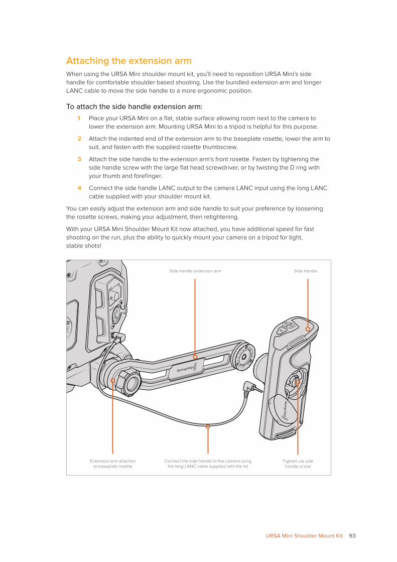
Attaching the extension armWhen using the URSA Mini shoulder mount kit, you’ll need to reposition URSA Mini’s side handle for comfortable shoulder based shooting. Use the bundled extension arm and longer LANC cable to move the side handle to a more ergonomic position.
To attach the side handle extension arm:1 Place your URSA Mini on a flat, stable surface allowing room next to the camera to
lower the extension arm. Mounting URSA Mini to a tripod is helpful for this purpose.
2 Attach the indented end of the extension arm to the baseplate rosette, lower the arm to suit, and fasten with the supplied rosette thumbscrew.
3 Attach the side handle to the extension arm’s front rosette. Fasten by tightening the side handle screw with the large flat head screwdriver, or by twisting the D ring with your thumb and forefinger.
4 Connect the side handle LANC output to the camera LANC input using the long LANC cable supplied with your shoulder mount kit.
You can easily adjust the extension arm and side handle to suit your preference by loosening the rosette screws, making your adjustment, then retightening.
With your URSA Mini Shoulder Mount Kit now attached, you have additional speed for fast shooting on the run, plus the ability to quickly mount your camera on a tripod for tight, stable shots!
Connect the side handle to the camera using the long LANC cable supplied with the kit
Side handleSide handle extension arm
Extension arm attaches to baseplate rosette
Tighten via side handle screw
93URSA Mini Shoulder Mount Kit
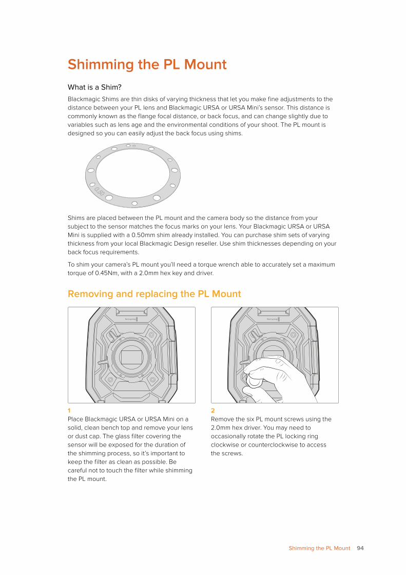
Shimming the PL MountWhat is a Shim?Blackmagic Shims are thin disks of varying thickness that let you make fine adjustments to the distance between your PL lens and Blackmagic URSA or URSA Mini’s sensor. This distance is commonly known as the flange focal distance, or back focus, and can change slightly due to variables such as lens age and the environmental conditions of your shoot. The PL mount is designed so you can easily adjust the back focus using shims.
Shims are placed between the PL mount and the camera body so the distance from your subject to the sensor matches the focus marks on your lens. Your Blackmagic URSA or URSA Mini is supplied with a 0.50mm shim already installed. You can purchase shim sets of varying thickness from your local Blackmagic Design reseller. Use shim thicknesses depending on your back focus requirements.
To shim your camera’s PL mount you’ll need a torque wrench able to accurately set a maximum torque of 0.45Nm, with a 2.0mm hex key and driver.
Removing and replacing the PL Mount
1 Place Blackmagic URSA or URSA Mini on a solid, clean bench top and remove your lens or dust cap. The glass filter covering the sensor will be exposed for the duration of the shimming process, so it’s important to keep the filter as clean as possible. Be careful not to touch the filter while shimming the PL mount.
2 Remove the six PL mount screws using the 2.0mm hex driver. You may need to occasionally rotate the PL locking ring clockwise or counterclockwise to access the screws.
94Shimming the PL Mount
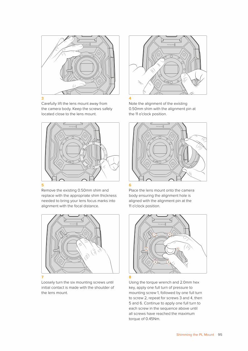
0.50
3 Carefully lift the lens mount away from the camera body. Keep the screws safely located close to the lens mount.
4 Note the alignment of the existing 0.50mm shim with the alignment pin at the 11 o’clock position.
0.50
0.50
0.50
5 Remove the existing 0.50mm shim and replace with the appropriate shim thickness needed to bring your lens focus marks into alignment with the focal distance.
6 Place the lens mount onto the camera body ensuring the alignment hole is aligned with the alignment pin at the 11 o’clock position.
1 3
6 5
4 2
7 Loosely turn the six mounting screws until initial contact is made with the shoulder of the lens mount.
8 Using the torque wrench and 2.0mm hex key, apply one full turn of pressure to mounting screw 1, followed by one full turn to screw 2, repeat for screws 3 and 4, then 5 and 6. Continue to apply one full turn to each screw in the sequence above until all screws have reached the maximum torque of 0.45Nm.
95Shimming the PL Mount
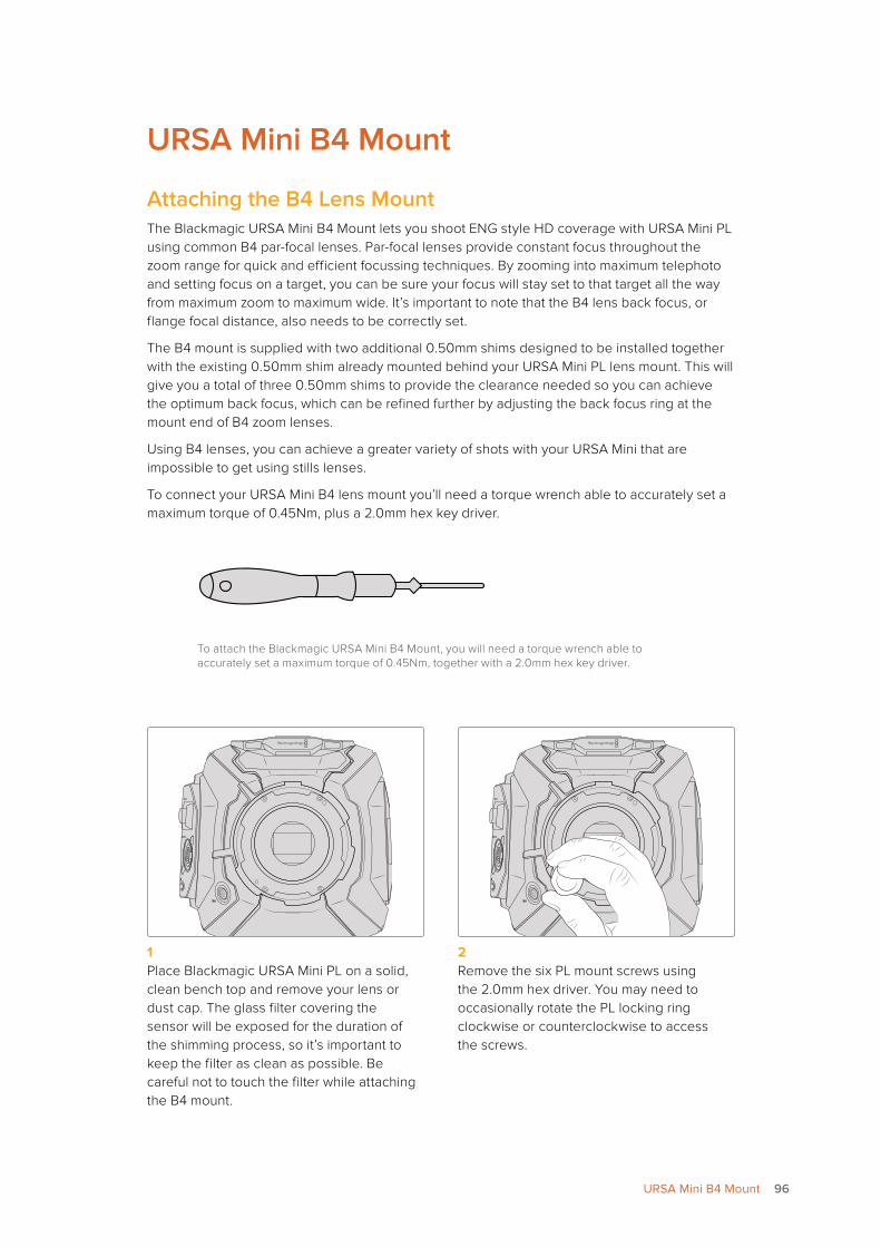
URSA Mini B4 Mount
Attaching the B4 Lens MountThe Blackmagic URSA Mini B4 Mount lets you shoot ENG style HD coverage with URSA Mini PL using common B4 par-focal lenses. Par-focal lenses provide constant focus throughout the zoom range for quick and efficient focussing techniques. By zooming into maximum telephoto and setting focus on a target, you can be sure your focus will stay set to that target all the way from maximum zoom to maximum wide. It’s important to note that the B4 lens back focus, or flange focal distance, also needs to be correctly set.
The B4 mount is supplied with two additional 0.50mm shims designed to be installed together with the existing 0.50mm shim already mounted behind your URSA Mini PL lens mount. This will give you a total of three 0.50mm shims to provide the clearance needed so you can achieve the optimum back focus, which can be refined further by adjusting the back focus ring at the mount end of B4 zoom lenses.
Using B4 lenses, you can achieve a greater variety of shots with your URSA Mini that are impossible to get using stills lenses.
To connect your URSA Mini B4 lens mount you’ll need a torque wrench able to accurately set a maximum torque of 0.45Nm, plus a 2.0mm hex key driver.
To attach the Blackmagic URSA Mini B4 Mount, you will need a torque wrench able to accurately set a maximum torque of 0.45Nm, together with a 2.0mm hex key driver.
1 Place Blackmagic URSA Mini PL on a solid, clean bench top and remove your lens or dust cap. The glass filter covering the sensor will be exposed for the duration of the shimming process, so it’s important to keep the filter as clean as possible. Be careful not to touch the filter while attaching the B4 mount.
2 Remove the six PL mount screws using the 2.0mm hex driver. You may need to occasionally rotate the PL locking ring clockwise or counterclockwise to access the screws.
96URSA Mini B4 Mount
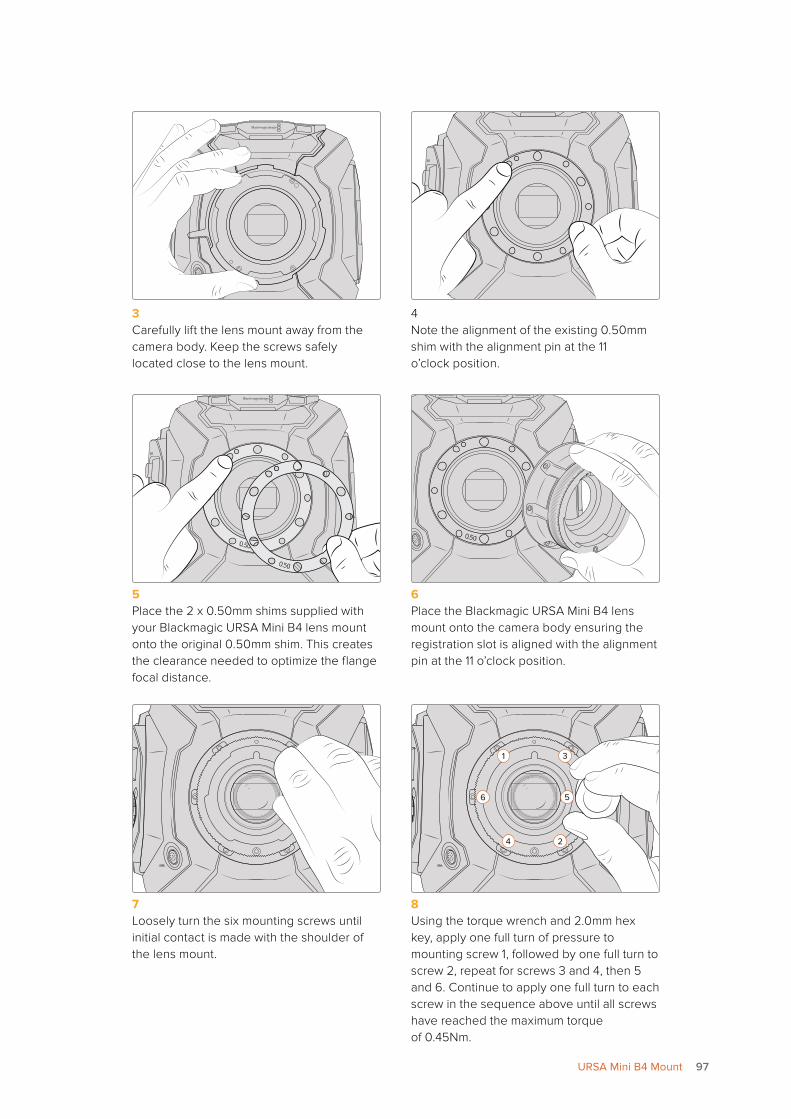
3 Carefully lift the lens mount away from the camera body. Keep the screws safely located close to the lens mount.
4 Note the alignment of the existing 0.50mm shim with the alignment pin at the 11 o’clock position.
0.50
0.50
0.50
5 Place the 2 x 0.50mm shims supplied with your Blackmagic URSA Mini B4 lens mount onto the original 0.50mm shim. This creates the clearance needed to optimize the flange focal distance.
6 Place the Blackmagic URSA Mini B4 lens mount onto the camera body ensuring the registration slot is aligned with the alignment pin at the 11 o’clock position.
1 3
6 5
4 2
7 Loosely turn the six mounting screws until initial contact is made with the shoulder of the lens mount.
8 Using the torque wrench and 2.0mm hex key, apply one full turn of pressure to mounting screw 1, followed by one full turn to screw 2, repeat for screws 3 and 4, then 5 and 6. Continue to apply one full turn to each screw in the sequence above until all screws have reached the maximum torque of 0.45Nm.
97URSA Mini B4 Mount
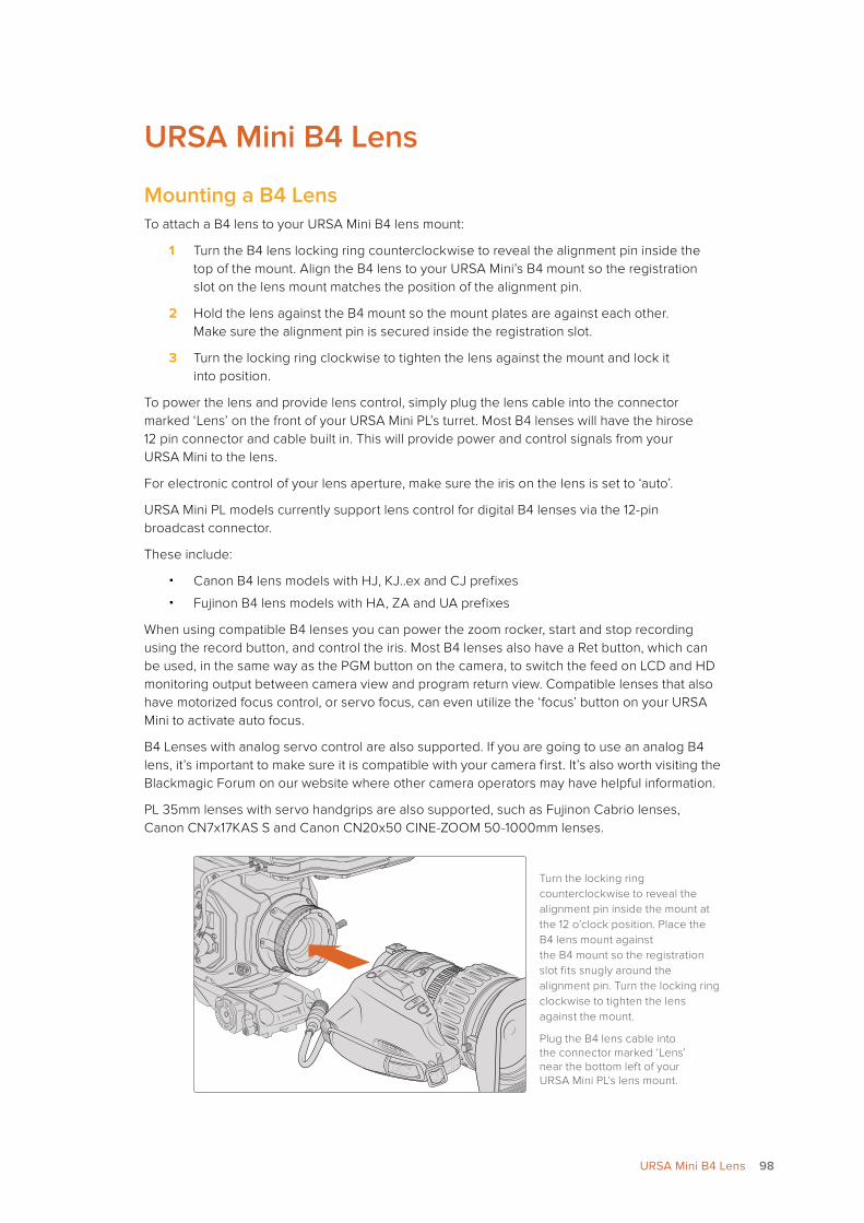
URSA Mini B4 Lens
Mounting a B4 LensTo attach a B4 lens to your URSA Mini B4 lens mount:
1 Turn the B4 lens locking ring counterclockwise to reveal the alignment pin inside the top of the mount. Align the B4 lens to your URSA Mini’s B4 mount so the registration slot on the lens mount matches the position of the alignment pin.
2 Hold the lens against the B4 mount so the mount plates are against each other. Make sure the alignment pin is secured inside the registration slot.
3 Turn the locking ring clockwise to tighten the lens against the mount and lock it into position.
To power the lens and provide lens control, simply plug the lens cable into the connector marked ‘Lens’ on the front of your URSA Mini PL’s turret. Most B4 lenses will have the hirose 12 pin connector and cable built in. This will provide power and control signals from your URSA Mini to the lens.
For electronic control of your lens aperture, make sure the iris on the lens is set to ‘auto’.
URSA Mini PL models currently support lens control for digital B4 lenses via the 12-pin broadcast connector.
These include:
� Canon B4 lens models with HJ, KJ..ex and CJ prefixes
� Fujinon B4 lens models with HA, ZA and UA prefixes
When using compatible B4 lenses you can power the zoom rocker, start and stop recording using the record button, and control the iris. Most B4 lenses also have a Ret button, which can be used, in the same way as the PGM button on the camera, to switch the feed on LCD and HD monitoring output between camera view and program return view. Compatible lenses that also have motorized focus control, or servo focus, can even utilize the ‘focus’ button on your URSA Mini to activate auto focus.
B4 Lenses with analog servo control are also supported. If you are going to use an analog B4 lens, it’s important to make sure it is compatible with your camera first. It’s also worth visiting the Blackmagic Forum on our website where other camera operators may have helpful information.
PL 35mm lenses with servo handgrips are also supported, such as Fujinon Cabrio lenses, Canon CN7x17KAS S and Canon CN20x50 CINE-ZOOM 50-1000mm lenses.
Turn the locking ring counterclockwise to reveal the alignment pin inside the mount at the 12 o’clock position. Place the B4 lens mount against the B4 mount so the registration slot fits snugly around the alignment pin. Turn the locking ring clockwise to tighten the lens against the mount.
Plug the B4 lens cable into the connector marked ‘Lens’ near the bottom left of your URSA Mini PL’s lens mount.
ZOOMF1
F2
F3
DISP
PEAK
LENS
98URSA Mini B4 Lens
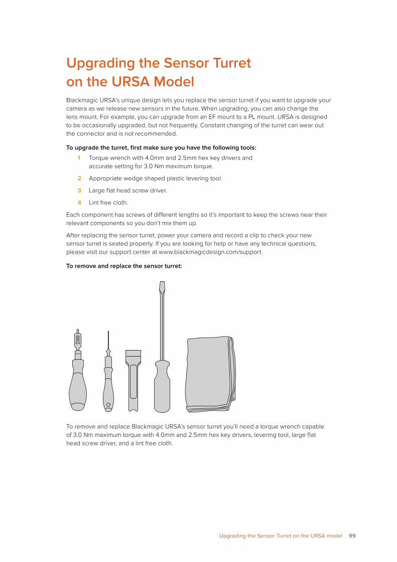
Upgrading the Sensor Turret on the URSA ModelBlackmagic URSA’s unique design lets you replace the sensor turret if you want to upgrade your camera as we release new sensors in the future. When upgrading, you can also change the lens mount. For example, you can upgrade from an EF mount to a PL mount. URSA is designed to be occasionally upgraded, but not frequently. Constant changing of the turret can wear out the connector and is not recommended.
To upgrade the turret, first make sure you have the following tools:
1 Torque wrench with 4.0mm and 2.5mm hex key drivers and accurate setting for 3.0 Nm maximum torque.
2 Appropriate wedge shaped plastic levering tool.
3 Large flat head screw driver.
4 Lint free cloth.
Each component has screws of different lengths so it’s important to keep the screws near their relevant components so you don’t mix them up.
After replacing the sensor turret, power your camera and record a clip to check your new sensor turret is seated properly. If you are looking for help or have any technical questions, please visit our support center at www.blackmagicdesign.com/support.
To remove and replace the sensor turret:
To remove and replace Blackmagic URSA’s sensor turret you’ll need a torque wrench capable of 3.0 Nm maximum torque with 4.0mm and 2.5mm hex key drivers, levering tool, large flat head screw driver, and a lint free cloth.
99Upgrading the Sensor Turret on the URSA model
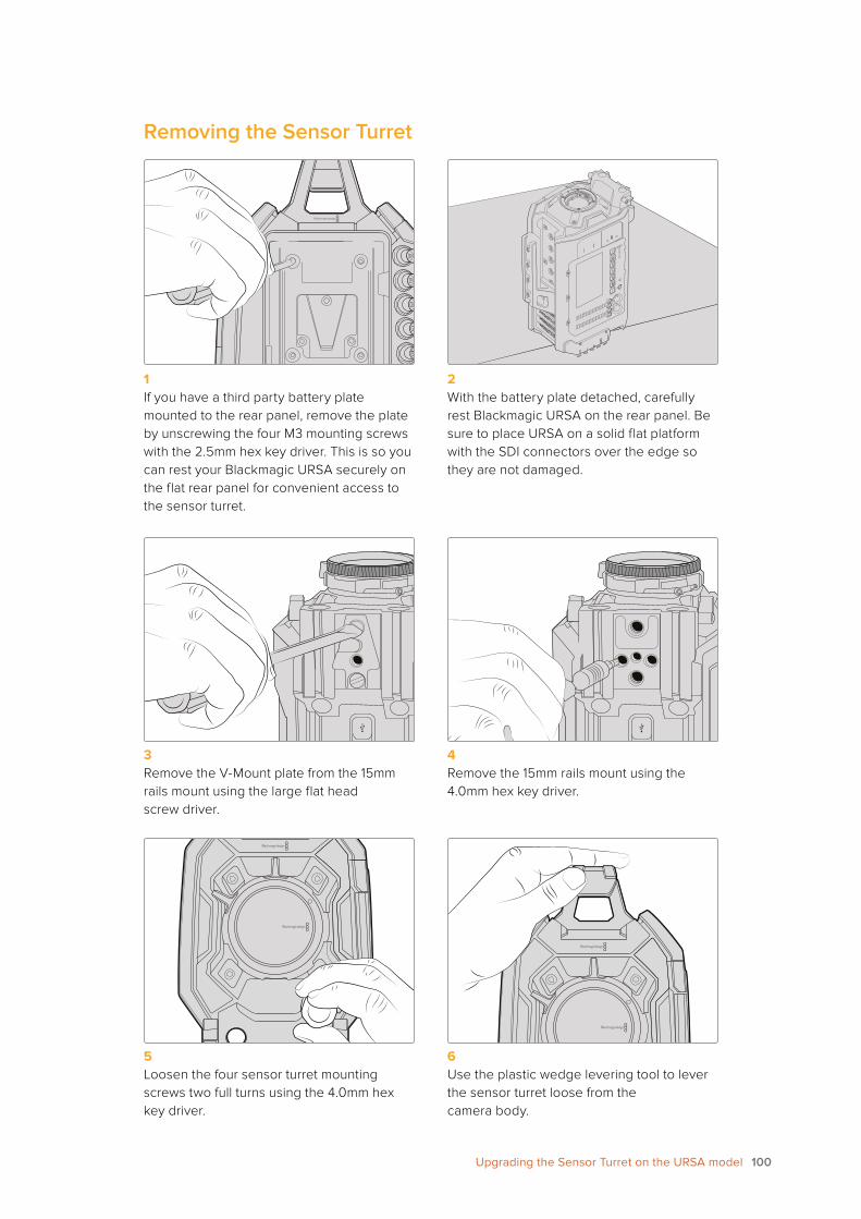
Removing the Sensor Turret
RE
F I
N
+1
2V
TIM
EC
OD
E I
N
CH
2M
UT
E
IRIS
FO
CU
SP
EA
KD
ISP
ME
NU
AU
DIO
IN
SD
I O
UT
+1
2V
OU
T
SLA
TE
TIM
EC
OD
E O
UT
0
-6
-12
-18
-24
-30
-36
-42
-48
SD
I O
UT
SD
I IN
CH
1S
OLO
CH
2S
OLO
CH
1M
UT
E
1 If you have a third party battery plate mounted to the rear panel, remove the plate by unscrewing the four M3 mounting screws with the 2.5mm hex key driver. This is so you can rest your Blackmagic URSA securely on the flat rear panel for convenient access to the sensor turret.
2 With the battery plate detached, carefully rest Blackmagic URSA on the rear panel. Be sure to place URSA on a solid flat platform with the SDI connectors over the edge so they are not damaged.
3 Remove the V-Mount plate from the 15mm rails mount using the large flat head screw driver.
4 Remove the 15mm rails mount using the 4.0mm hex key driver.
5 Loosen the four sensor turret mounting screws two full turns using the 4.0mm hex key driver.
6 Use the plastic wedge levering tool to lever the sensor turret loose from the camera body.
100Upgrading the Sensor Turret on the URSA model
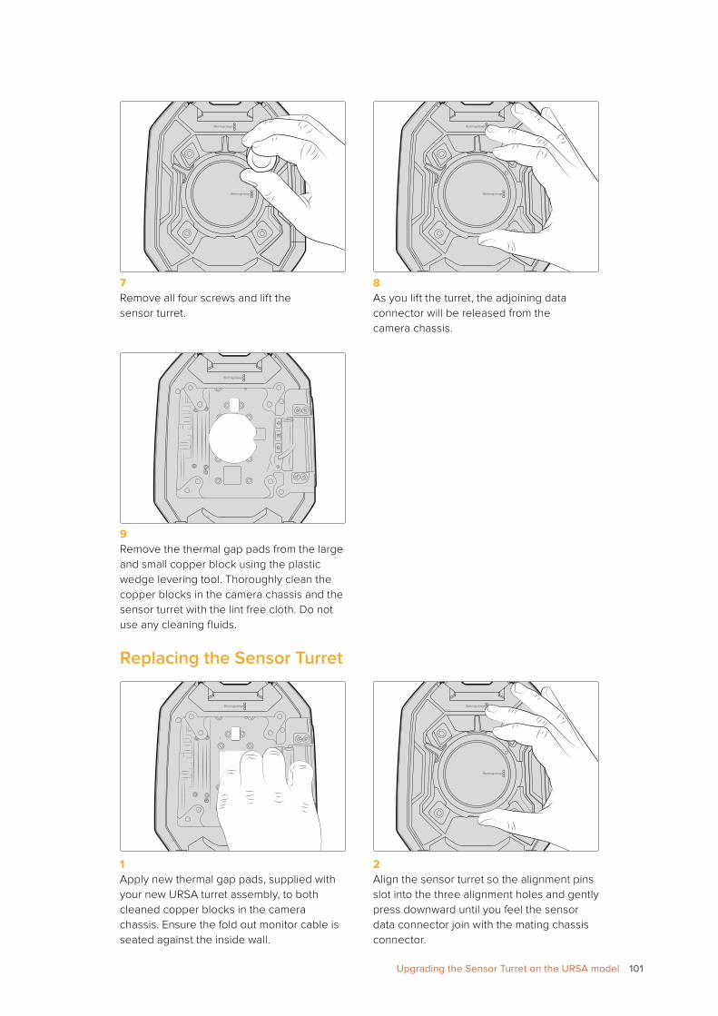
7 Remove all four screws and lift the sensor turret.
8 As you lift the turret, the adjoining data connector will be released from the camera chassis.
9 Remove the thermal gap pads from the large and small copper block using the plastic wedge levering tool. Thoroughly clean the copper blocks in the camera chassis and the sensor turret with the lint free cloth. Do not use any cleaning fluids.
Replacing the Sensor Turret
1 Apply new thermal gap pads, supplied with your new URSA turret assembly, to both cleaned copper blocks in the camera chassis. Ensure the fold out monitor cable is seated against the inside wall.
2 Align the sensor turret so the alignment pins slot into the three alignment holes and gently press downward until you feel the sensor data connector join with the mating chassis connector.
101Upgrading the Sensor Turret on the URSA model
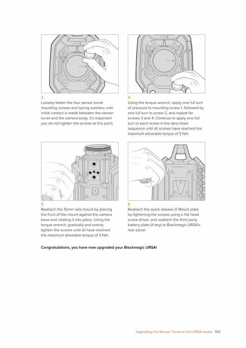
1 3
4
2
3 Loosely fasten the four sensor turret mounting screws and spring washers until initial contact is made between the sensor turret and the camera body. It’s important you do not tighten the screws at this point.
4 Using the torque wrench, apply one full turn of pressure to mounting screw 1, followed by one full turn to screw 2, and repeat for screws 3 and 4. Continue to apply one full turn to each screw in the described sequence until all screws have reached the maximum allowable torque of 3 Nm.
5 Reattach the 15mm rails mount by placing the front of the mount against the camera base and rotating it into place. Using the torque wrench, gradually and evenly tighten the screws until all have reached the maximum allowable torque of 3 Nm.
6 Reattach the quick release V-Mount plate by tightening the screws using a flat head screw driver, and reattach the third party battery plate (if any) to Blackmagic URSA’s rear panel.
Congratulations, you have now upgraded your Blackmagic URSA!
102Upgrading the Sensor Turret on the URSA model
Help
Getting HelpThe fastest way to obtain help is to go to the Blackmagic Design online support pages and check the latest support material available for your camera.
Blackmagic Design Online Support PagesThe latest manual, software and support notes can be found at the Blackmagic Design support center at www.blackmagicdesign.com/support.
Contacting Blackmagic Design SupportIf you can’t find the help you need in our support material, please use the “Send us an email” button on the support page to email a support request. Alternatively, click on the “Find your local support team” button on the support page and call your nearest Blackmagic Design support office.
Checking the Software Version Currently InstalledTo check which version of Blackmagic Camera Utility software is installed on your computer, open the About Blackmagic Camera Utility window.
� On Mac OS X, open Blackmagic Camera Utility from the Applications folder. Select About Blackmagic Camera Utility from the application menu to reveal the version number.
� On Windows, open Blackmagic Camera Utility from your Start menu or Start Screen. Click on the Help menu and select About Blackmagic Camera Utility to reveal the version number.
How to Get the Latest Software UpdatesAfter checking the version of Blackmagic Camera Utility software installed on your computer, please visit
the Blackmagic Design support center at www.blackmagicdesign.com/support to check for the latest updates. While it is usually a good idea to run the latest updates, it is wise to avoid updating any software if you are in the middle of an important project.
103103Help
Warranty
Limited WarrantyBlackmagic Design warrants that this product will be free from defects in materials and workmanship for a period of 12 months from the date of purchase. If a product proves to be defective during this warranty period, Blackmagic Design, at its option, either will repair the defective product without charge for parts and labor, or will provide a replacement in exchange for the defective product.
In order to obtain service under this warranty, you the Customer, must notify Blackmagic Design of the defect before the expiration of the warranty period and make suitable arrangements for the performance of service. The Customer shall be responsible for packaging and shipping the defective product to a designated service center nominated by Blackmagic Design, with shipping charges pre paid. Customer shall be responsible for paying all shipping charges, insurance, duties, taxes, and any other charges for products returned to us for any reason.
This warranty shall not apply to any defect, failure or damage caused by improper use or improper or inadequate maintenance and care. Blackmagic Design shall not be obliged under this warranty: a) to repair damage resulting from attempts by personnel other than Blackmagic Design representatives to install, repair or service the product, b) to repair damage resulting from improper use or connection to incompatible equipment, c) to repair any damage or malfunction caused by the use of non Blackmagic Design parts or supplies, or d) to service a product that has been modified or integrated with other products when the effect of such a modification or integration increases the time or difficulty of servicing the product.
Exposing URSA Viewfinder to direct sunlight could damage the viewfinder display as the viewfinder optics act as a magnifying glass. Image retention or burn-in could happen on OLED panels when static or high contrast images, such as frame guides, are displayed on the panels for extended periods. To avoid this, ensure the IR sensor for face detection is not covered deliberately and disconnect the viewfinder when not in use for prolonged periods. Image retention is not covered by this product warranty.
THIS WARRANTY IS GIVEN BY BLACKMAGIC DESIGN IN LIEU OF ANY OTHER WARRANTIES, EXPRESS OR IMPLIED. BLACKMAGIC DESIGN AND ITS VENDORS DISCLAIM ANY IMPLIED WARRANTIES OF MERCHANTABILITY OR FITNESS FOR A PARTICULAR PURPOSE. BLACKMAGIC DESIGN’S RESPONSIBILITY TO REPAIR OR REPLACE DEFECTIVE PRODUCTS DURING THE WARRANTY PERIOD IS THE WHOLE AND EXCLUSIVE REMEDY PROVIDED TO THE CUSTOMER. BLACKMAGIC DESIGN WILL NOT BE LIABLE FOR ANY INDIRECT, SPECIAL, INCIDENTAL OR CONSEQUENTIAL DAMAGES IRRESPECTIVE OF WHETHER BLACKMAGIC DESIGN OR THE VENDOR HAS ADVANCE NOTICE OF THE POSSIBILITY OF SUCH DAMAGES. BLACKMAGIC DESIGN IS NOT LIABLE FOR ANY ILLEGAL USE OF EQUIPMENT BY CUSTOMER. BLACKMAGIC IS NOT LIABLE FOR ANY DAMAGES RESULTING FROM USE OF THIS PRODUCT. USER OPERATES THIS PRODUCT AT OWN RISK.
© Copyright 2016 Blackmagic Design. All rights reserved. ‘Blackmagic Design’, ‘URSA’, ‘DeckLink’, ‘HDLink’, ‘Workgroup Videohub’, ‘Multibridge Pro’, ‘Multibridge Extreme’, ‘Intensity’ and ‘Leading the creative video revolution’ are registered trademarks in the US and other countries. All other company and product names may be trademarks of the respective companies with which they are associated.
104104Warranty