URGENT LEGAL MATTER SENT VIA ELECTRONIC … LEGAL MATTER SENT VIA ELECTRONIC MAIL Grenada...
33
UNITED STATES ENVIRONMENTAL PROTECTION AGENCY REGION 4 SAM NUNN ATLANTA FEDERAL CENTER 61 FORSYTH STREET ATLANTA, GEORGIA 30303-8960 December 30, 2015 URGENT LEGAL MATTER SENT VIA ELECTRONIC MAIL Grenada Manufacturing, LLC c/o Mr. Jimmy I. Palmer 778 Shady Oaks Circle Oxford, Mississippi 38655 Re: Request for Additional Interim Measures at the Grenada Manufacturing, LLC, Facility in Grenada, Grenada County, Mississippi Dear Mr. Palmer: The purpose of this letter is to follow up on prior requests made by the U.S. Environmental Protection Agency for your client, Grenada Manufacturing, LLC (Grenada Manufacturing or Permittee), to conduct additional interim measures pursuant to its EPA Hazardous and Solid Waste Amendment Permit (HSWA Permit), I.D. No. MSD 007037278, issued July 29, 2010. Specifically, on December 3, 2015, the EPA sent Don Williams, on behalf of Grenada Manufacturing, an email (see Enclosure A) requesting performance by mid-December of certain interim measures relating to additional ambient air investigations. During the December 11, 2015, meeting between representatives from the EPA, Grenada Manufacturing, and Meritor, Inc., at the EPA Region 4 offices in Atlanta, GA, the EPA again highlighted the need for prompt performance of this ambient air investigation. Recognizing that some delay in response may be attributable to Grenada Manufacturing only recently securing new legal counsel, the EPA is concerned that Grenada Manufacturing has provided no indication to date of its willingness to perform the requested actions. This letter therefore serves to more formally outline and detail the necessary interim actions and to clarify the EPA’s expectations for next steps and timing. Pursuant to Condition II.F of the HSWA Permit, the EPA hereby notifies Grenada Manufacturing that it shall update the existing Interim Measures Work Plan (IMWP), dated September 11, 2015 (see Enclosure B), to reflect all off-site and on-site corrective actions outlined below and discussed during the December 11, 2015, meeting and within the December 3, 2015, request. Consistent with Conditions II.F.1.a and II.F.1.c of the HSWA Permit, the updated IMWP shall be submitted within thirty (30) calendar days of Grenada Manufacturing’s receipt of this letter, and shall include all interim measures objectives, as well procedures and schedules for implementation. The EPA requests that all of the following interim measures be conducted to mitigate any current or potential threats to human health or the environment and be consistent with and integrated into any long-term solution at the Grenada Manufacturing facility:
Transcript of URGENT LEGAL MATTER SENT VIA ELECTRONIC … LEGAL MATTER SENT VIA ELECTRONIC MAIL Grenada...

UNITED STATES ENVIRONMENTAL PROTECTION AGENCY
REGION 4
SAM NUNN ATLANTA FEDERAL CENTER
61 FORSYTH STREET
ATLANTA, GEORGIA 30303-8960
December 30, 2015
URGENT LEGAL MATTER
SENT VIA ELECTRONIC MAIL
Grenada Manufacturing, LLC
c/o Mr. Jimmy I. Palmer
778 Shady Oaks Circle
Oxford, Mississippi 38655
Re: Request for Additional Interim Measures at the Grenada Manufacturing, LLC, Facility in
Grenada, Grenada County, Mississippi
Dear Mr. Palmer:
The purpose of this letter is to follow up on prior requests made by the U.S. Environmental Protection
Agency for your client, Grenada Manufacturing, LLC (Grenada Manufacturing or Permittee), to conduct
additional interim measures pursuant to its EPA Hazardous and Solid Waste Amendment Permit
(HSWA Permit), I.D. No. MSD 007037278, issued July 29, 2010. Specifically, on December 3, 2015,
the EPA sent Don Williams, on behalf of Grenada Manufacturing, an email (see Enclosure A)
requesting performance by mid-December of certain interim measures relating to additional ambient air
investigations. During the December 11, 2015, meeting between representatives from the EPA, Grenada
Manufacturing, and Meritor, Inc., at the EPA Region 4 offices in Atlanta, GA, the EPA again
highlighted the need for prompt performance of this ambient air investigation. Recognizing that some
delay in response may be attributable to Grenada Manufacturing only recently securing new legal
counsel, the EPA is concerned that Grenada Manufacturing has provided no indication to date of its
willingness to perform the requested actions. This letter therefore serves to more formally outline and
detail the necessary interim actions and to clarify the EPA’s expectations for next steps and timing.
Pursuant to Condition II.F of the HSWA Permit, the EPA hereby notifies Grenada Manufacturing that it
shall update the existing Interim Measures Work Plan (IMWP), dated September 11, 2015 (see
Enclosure B), to reflect all off-site and on-site corrective actions outlined below and discussed during
the December 11, 2015, meeting and within the December 3, 2015, request. Consistent with Conditions
II.F.1.a and II.F.1.c of the HSWA Permit, the updated IMWP shall be submitted within thirty (30)
calendar days of Grenada Manufacturing’s receipt of this letter, and shall include all interim measures
objectives, as well procedures and schedules for implementation. The EPA requests that all of the
following interim measures be conducted to mitigate any current or potential threats to human health or
the environment and be consistent with and integrated into any long-term solution at the Grenada
Manufacturing facility:

A. Off-site Corrective Actions:
1) Conduct comprehensive ambient air investigation to identify sources of trichloroethylene (TCE)
and related contaminants detected in the September 2015 vapor intrusion (VI) study (see below
regarding the EPA’s current plans for this action item);
2) Conduct second round of soil gas, sub-slab, and indoor air sampling in homes previously sampled
during the September 2015 VI study and expand the investigation as directed by the EPA to
additional homes on Lyon Drive and other possible roads in the Eastern Heights neighborhood.
Such investigation must continue until potential sources (e.g. ambient air, groundwater) are
eliminated or remediated;
3) Complete delineation of groundwater contamination at or adjacent to the Grenada Manufacturing
facility, including the Eastern Heights neighborhood;
4) Develop and implement interim measures to control and remediate off-site contaminated
groundwater; and
5) Conduct any other measures determined to be necessary to protect the residents in the nearby
neighborhood as data is received.
B. On-site Corrective Actions:
1) Prevent releases of contaminants to Riverdale Creek. This includes a thorough investigation of and
recommendations for upgrading the existing permeable reactive barrier (PRB). If no feasible and
timely solution to the PRB is available, develop, install, and operate alternative control measures;
2) Develop and implement interim measures to remediate contaminated groundwater beneath the
facility. Groundwater contaminant levels have remained at elevated levels 10 years after
installation of the site-wide groundwater remedy (the PRB was installed in 2005);
3) Assess and remediate Solid Waste Management Units (SWMUs) that were previously recognized
as “No further action until taken out of service,” and which are now out of service. The EPA
understands that SWMU 13, the wastewater treatment plant, is no longer in service; and
4) Conduct sampling of lower aquifer production wells to determine if any impact has occurred from
prior facility operations. Currently, only one monitoring well accesses the lower aquifer and the
EPA believes that a comprehensive review is necessary to determine if any impact has occurred.
The EPA has completed its initial review of the September 2015 VI study, including analysis of indoor
air, ambient air, and groundwater data from or beneath six (6) homes in the Eastern Heights
neighborhood. Based on the sampling results, the EPA believes that a more comprehensive ambient air
investigation is necessary to determine the source of TCE and related contaminants detected in the
ambient air above the EPA’s regional screening levels, but below levels that require a response action at
this time. As a result, combined with Grenada Manufacturing’s failure to respond to the EPA’s
December 3, 2015, request, the EPA is arranging for its Science and Ecosystem Support Division to
conduct the ambient air sampling within the next two weeks. The EPA requests that Grenada
Manufacturing take over the investigation if or when additional rounds of ambient air sampling are
determined to be necessary.
While the EPA seeks Grenada Manufacturing’s cooperation with this request, compliance with the
request is required by Conditions I.D and II.F of the HSWA Permit and 40 C.F.R. §§ 270.30(a) and
264.101. Failure to respond within the timeframe specified above may result in an enforcement action,
permit termination, revocation and re-issuance, modification, or denial of a permit renewal application.
The EPA strongly encourages Grenada Manufacturing to give this matter its immediate attention. The
EPA is available to discuss specific details of this letter and/or any other aspects of the HSWA Permit at
your earliest convenience. To arrange a conference call or discuss any specific questions, please contact

me at (404) 562-9554, or Greg D. Luetscher, Associate Regional Counsel, at 404-562-9677. Thank you
for your cooperation in this matter.
Sincerely,
/Stephen P. Smith/
Stephen P. Smith
Associate Regional Counsel
Enclosures
cc: Don Williams, Grenada Manufacturing, LLC (via electronic mail)
Trey Hess, Mississippi Department of Environmental Quality (via electronic mail)

From: Bastek, Brian Sent: Thursday, December 03, 2015 3:28 PM To: 'Don Williams' <[email protected]> Cc: 'Ellis, John' <[email protected]>; Anderson, Meredith <[email protected]> Subject: Granada Manufacturing, LLC - Air Data Transmittal Mr. Williams, The EPA has completed its initial review of the VI Study air and groundwater data. Based on the sampling results, the EPA believes that a more comprehensive ambient air investigation is necessary to determine the source of the TCE being detected above EPA’s screening levels. Please see the rationale below. TCE is showing up in some of the groundwater samples well above MCLs and screening levels for vapor intrusion, but as suggested in Arcadis’s comments, it does not appear to be migrating directly from the sub-surface soil gas to the residential indoor air. TCE was detected in the ambient air samples at levels comparable to the indoor air samples, which are above EPA’s screening levels. Thus it appears that the TCE could be migrating from the subsurface source area(s) to the surface somewhere away from the residences, and then be getting transported to the residential area via ambient air. Or, alternatively, there could possibly be another above-ground source of the TCE that is being transported to the residential area via ambient air. More ambient air sampling is needed to pinpoint the source/migration pathway for the airborne TCE. The EPA recommends that real-time instrumentation, in addition to 24 hour ambient air samples, be utilized in the identification of the ambient TCE source and that the investigation be conducted in all directions from the previous two locations, 1-AA and 2-AA. Any potential suspected sources of TCE in the area should be targeted for sampling, such as the Grenada Manufacturing process buildings, the EQ basin, the former wastewater treatment unit, any areas of daylighting groundwater or springs, and upwind and downwind locations. This field work shall be conducted as soon as possible and no later than mid-December 2015 in accordance with the currently-approved IM work plan dated September 11, 2015. The EPA is available to discuss specific details of this investigation including sample locations; please contact me by 12/4/15 to set up a conference call. Brian Bastek Environmental Engineer U.S. EPA, Region 4 RCRA Corrective Action and Permitting Section Resource Conservation and Restoration Division 61 Forsyth Street, SW Atlanta, GA 30303 404-562-8511 [email protected]

Grenada Manufacturing, LLC
635 Hwy 332 662-226-1161 Grenada, Ms 38901 662-226-1166 Fax
Via Electronic Mail and Overnight Delivery September 11, 2015 Mr. Brian Bastek ([email protected]) RCRA Corrective Action and Permitting Section RCRA Cleanup and Brownfields Branch U.S. Environmental Protection Agency Region 4, Atlanta Federal Center 61 Forsyth Street Atlanta, GA 30303-8960 Re: Submission of Final Revised Interim Measures Work Plan EPA HSWA Permit No. MSD 007 037 278, July 29, 2010 Grenada Manufacturing, LLC, Grenada, Mississippi Dear Mr. Bastek: On behalf of Grenada Manufacturing, LLC, I have enclosed the Final Revised Interim Measures Work Plan requested in your letter of September 4, 2015. The revisions address the comments provided in the letter as well as comments provided during discussions with the agency. Mr. John Ellis of ARCADIS U.S., Inc., will continue to serve as the Project Manager on this matter. Please do not hesitate to contact Mr. Ellis at 225-292-1004 if you have any questions regarding the enclosed work plan. Sincerely, Grenada Manufacturing, LLC c/o Mr. Donald Williams 635 Highway 332 Grenada, MS 38901 Enclosure cc: Ms. Carla Brown, Mississippi Department of Environmental Quality Mr. John Ellis, ARCADIS U.S., Inc.

Imagine the result
Mr. Donald Williams Grenada Manufacturing, LLC 635 Highway 332 Grenada, Mississippi 38901
Subject:
Final Revised Interim Measures Work Plan – Vapor Intrusion Assessment Grenada Manufacturing, LLC, Grenada, Mississippi. Permit No. MSD 007 037 278 Dear Mr. Williams:
ARCADIS is pleased to provide this Final Revised Interim Measures Work Plan (IMWP) to Grenada Manufacturing, LLC (Grenada Manufacturing) for its facility located in Grenada, Mississippi, detailing the proposed Vapor Intrusion (VI) Assessment and supplemental soil and groundwater sampling. The revisions to the IMWP incorporate comments provided by the U.S. Environmental Protection Agency (USEPA). This IMWP has been prepared in response to the June 30, 2015, August 20, 2015, and September 4, 2015, USEPA Region 4 letters to Grenada Manufacturing, in which the USEPA requested performance by Grenada Manufacturing of the tasks identified therein pursuant to the company’s Hazardous and Solid Waste (HSWA) permit. The IMWP outlines screening, field work, laboratory analysis, data evaluation, and reporting proposed for the scope of work, which will be conducted in accordance with the USEPA OSWER Technical Guide for Assessing and Mitigating the Vapor Intrusion Pathway from Subsurface Vapor Sources to Indoor Air (USEPA June 2015) and, as appropriate, USEPA Region 4 protocols.
Background
The manufacturing facility was constructed by Lyon in 1961 and sold to Rockwell International Corporation (Rockwell) in 1966. Rockwell operated a wheel cover manufacturing facility from 1966 to 1985, when the plant and property were sold to Textron, Inc. (Textron), formerly Randall Textron. In 1999, Textron sold the operations and property to Grenada Manufacturing, who continued to operate the wheel cover plant until 2008 when portions of the property were leased to ICE Industries, Inc. (ICE). Following ICE’s lease of the premises, the facility was converted to a stamping plant, providing stamp-formed parts for various industries.
During prior groundwater investigation activities performed at the facility, an elevated concentration of trichloroethylene (TCE) was detected in a groundwater sample collected from off-site Monitoring Well MW-20 in a May 2012 sampling event.
ARCADIS U.S., Inc.
10352 Plaza Americana Drive
Baton Rouge
Louisiana
Tel 225-292-1004
Fax 225-218-9677
www.arcadis-us.com
ENVIRONMENT
Date:
September 11, 2015
Contact:
John Ellis
Extension:
208
Email:
Our ref:
IN000899.0013.00001 Grenada/IN899.13/C/1/bbn

Grenada/IN899.13/C/1/bbn
Mr. Donald Williams
September 11, 2015
Page:
2/13
Seventeen soil gas ports (VP-1 through VP-17) were installed and sampled in 2013 to further investigate this area. An additional six soil gas ports (VP-101, VP-103, VP108, VP-110, VP112, and VP-114) were installed and sampled during May 2014.
Groundwater samples were also obtained in the fall of 2012 and the spring of 2013 from sample locations WL-1, WL-2, WL-6, WL-10, WL-11, WL-12, WL-13, WL-15, WL-16, WL-17, and TW-18S/D. The sample locations correspond to the soil gas ports (VPs) with the same number. Given the construction of the soil gas ports, groundwater is sometimes encountered in ports and water samples are collected. Water samples were collected from (VP-1, VP-2, VP-4, VP-5, VP-6, VP-7, VP-8, VP-10, VP-11, VP-12, VP-14, VP-15, VP-16, VP-17, VP-101, VP-103, VP-106, VP-107, VP-108, VP-110, VP-112, and VP-114). The data and preliminary evaluation from the sampling were submitted to USEPA Region 4 in a letter dated January 17, 2014. A figure presenting the groundwater data obtained from the soil gas ports is provided in Attachment A. These data were collected using the methods described in the January 17, 2014, letter.
Figure 1 depicts the sample locations in relation to the off-site Monitoring Well MW-20 assessment area. The USEPA requested that Grenada Manufacturing prepare an IMWP to evaluate the potential VI pathway in the off-site area in a letter dated June 30, 2015. An IMWP was submitted on August 3, 2015. The USEPA provided comments on the IMWP in a letter dated August 20, 2015. A Revised IMWP was submitted to the USEPA on August 28, 2015. The USEPA provided additional comments in a letter dated September 4, 2015.
Scope of Work
In an effort to evaluate the potential VI pathway in the off-site area, additional air data will be collected. Samples collected will include:
Soil gas Ambient air Indoor air from select residential buildings Sub-slab vapor from select residential buildings
A reconnaissance of any building where indoor air and sub-slab vapor samples will be collected will be conducted prior to sampling.
The USEPA has also requested that sampling of groundwater conditions in the upper aquifer be conducted. Additionally, the USEPA requested the collection of soil samples during the groundwater sampling.
Details on the sampling procedures and data evaluations are provided below.

Grenada/IN899.13/C/1/bbn
Mr. Donald Williams
September 11, 2015
Page:
3/13
Any additional sampling beyond what is described in this IMWP will be based on the data evaluation. The evaluation will use the multiple lines of evidence (MLE) approach described in the USEPA OSWER Technical Guide for Assessing and Mitigating the Vapor Intrusion Pathway from Subsurface Vapor Sources to Indoor Air (USEPA June 2015). If the evaluation indicates that the VI pathway is incomplete, additional VI evaluation is not warranted.
Soil Gas Assessment
ARCADIS proposes to install and sample eight shallow soil gas ports as shown on Figure 1. These eight proposed off-site locations will be installed in proximity to the existing deeper soil gas ports (VP-2 through VP-6, VP-13, and VP-17), including the ones with the elevated TCE concentrations. A desktop review of the available soil borings and geological cross-sections shows that an approximate 8- to 12-foot-thick surficial clay layer underlain by a sand layer is present in this area. The existing soil gas ports with detected volatile organic compound (VOC) concentrations were screened at the clay/sand interface or within the water-bearing sand layer. ARCADIS will use the data to evaluate the migration of concentrations detected in the previously installed soil gas ports.
Soil Gas Port Installation
A truck mounted Geoprobe® will be used to create an open borehole, and a 2.25-inch-diameter Macro-Core® sampler will be used to remove soil from the boring. As part of the reconnaissance, a utility locate will be requested to identify buried utilities in the vicinity of the structures and any proposed soil gas ports prior to intrusive activities. Soil will be classified in the field and certain soil samples may be collected from select borings for soil moisture analysis. Each of the soil gas ports will be installed to a depth of 6 feet below ground surface and will be screened from the 5.5-foot to 6-foot interval below ground surface. Soil gas ports will be constructed of 0.25-inch nylon tubing with 6-inch stainless steel screens. The screen will be installed with filter pack sand placed around the screen to 6 inches above the screen. Granular bentonite will be used to fill the remainder of the borehole above the screen filter pack to the surface and hydrated during installation. A protective cover will be installed at the surface. At the surface, the end of the tubing will be equipped with a Swagelok® fitting and a gas tight valve. Upon completion of the installation and sealing of each soil gas port, the volume of air in the sand pack will be calculated and approximately 3 times this volume of air will be purged using a low-flow air sampling pump set at a rate of 100 milliliters per minute (mL/min).
Soil Gas Port Sampling
A minimum of 24 hours after installation, each soil gas port will be sampled using 1-liter polished stainless steel SUMMA® canisters with calibrated flow controllers that

Grenada/IN899.13/C/1/bbn
Mr. Donald Williams
September 11, 2015
Page:
4/13
are cleaned and certified by the laboratory. The flow controllers will be calibrated for a sampling duration of 10 minutes (≈ 80 mL/min). Approximately one to three times the dead volume of air will be purged at a rate of 100 mL/min prior to sampling using a low-flow air sampling pump. The amount and rate of dead volumes purged will be measured and recorded in the field and will remain consistent between sample locations. The sampling procedure consists of connecting the purge pump to the soil gas port, then turning it on, then opening the soil gas port valve to purge the tubing. At completion of purging, the valve on the soil gas port will be closed, the purge pump removed, and then the sampling canister and flow controller will be connected to the soil gas port. The sampling canister will be opened and then the valve on the soil gas port will be opened. At the completion of sampling, the canister will be closed first and then the soil gas port valve. A final canister vacuum between 2 and 5 inches of mercury will signify that sample collection is complete. At the completion of each sample collection, the Summa canisters will be closed and sealed with a brass Swagelok® cap.
Meteorological data (temperature, precipitation, humidity, barometric pressure, and wind speed/direction) will be collected before and during sampling activities.
Residential VI Assessment
In addition to the supplemental soil gas investigation, ARCADIS proposes to complete VI sampling at six residential properties located on Lyon Drive (as shown on Figure 1). Work will be conducted in accordance with the USEPA OSWER Technical Guide for Assessing and Mitigating the Vapor Intrusion Pathway from Subsurface Vapor Sources to Indoor Air (USEPA June 2015).
The six residential structures on Lyon Drive have been selected based on their relative proximity to known groundwater impacts (MW-20) and potential soil gas impacts (VP-2, VP-3, VP-5, VP-6). Only four of these structures are within 100 feet of the known groundwater or potential soil gas impacts (as shown on Figure 1). The other two properties, east and west of the potentially impacted area, are being assessed as a conservative measure. At this time, no preferential pathways have been identified in the area of potential impacts.
Community Outreach
Prior to engaging property owners regarding the residential VI sampling, the USEPA will conduct outreach with potentially affected community members. The purpose of this outreach will be to disseminate information regarding the Site history, constituents being assessed, vapor intrusion, sampling process, and obtaining access.
Residential VI sampling will be contingent on the USEPA obtaining approval and a signed access agreement from the property owners.

Grenada/IN899.13/C/1/bbn
Mr. Donald Williams
September 11, 2015
Page:
5/13
Reconnaissance of Structures
As recommended in USEPA guidance, prior to conducting sampling activities, a reconnaissance of the potentially affected structures will be performed. As appropriate, a visual inspection of the structure’s interiors and exteriors will be performed to identify potential preferential pathways (such as utilities) to potential vapor migration into the structures and to identify any background sources or other factors that could affect the quality of indoor air. As part of the reconnaissance, information will be gathered from the homeowner on potential sources within each structure, ventilation systems, and building construction. A copy of the indoor air building survey and sampling form is provided in Attachment B. Identified potential background sources will be removed from the structure during the VI sampling event. Samples collected from the residential structures will be given a unique identification to conceal the identity of the sample locations.
Review of the Grenada County Assessor records indicates that the houses along Lyon Drive are single-story buildings with slab-on-grade construction (no basements) and are less than 1,500 square feet in size. Thus, paired indoor air and sub-slab sampling is recommended at each structure.
The USEPA will collect information on the residences in the community during their outreach campaign.
Indoor Air Sampling
Indoor air samples will be collected using 6-liter polished stainless steel SUMMA® canisters with calibrated flow controllers that are cleaned and certified by the laboratory. The canisters will utilize flow controllers calibrated for a 24-hour sample collection. During the collection process, the indoor air canister will be securely positioned at the breathing zone level for the most sensitive exposed population and located near the center of the structure. Because all six of the structures identified for the residential VI assessment are single-story, slab-on-grade construction and are less than 1,500 square feet in size, one indoor air sample location is appropriate. All indoor air samples will be collected under normal home conditions. A final canister vacuum on the flow controller between 2 and 5 inches of mercury will signify that sample collection is complete. At the completion of sampling, the canister will be closed and the flow controller removed. The canisters will be gauged with an independent gauge and the final vacuum recorded. The canister will then be closed and sealed with a brass Swagelok® cap.
Meteorological data (temperature, precipitation, humidity, barometric pressure, and wind speed/direction) will be collected before and during sampling activities.

Grenada/IN899.13/C/1/bbn
Mr. Donald Williams
September 11, 2015
Page:
6/13
Ambient Air Sampling
Ambient air samples will be collected outdoors concurrently with indoor air samples to evaluate potential background contaminant sources from outside the structures. Ambient air samples will be collected using 6-liter polished stainless steel SUMMA® canisters with calibrated flow controllers that are cleaned and certified by the laboratory. The canisters will utilize flow controllers calibrated for a 24-hour sample collection. During the collection process, the sample canister will be securely positioned at breathing height (approximately 5 feet above the ground). It is anticipated that all structures will not be sampled at the same time. It is proposed that, instead of collecting ambient air samples at each structure location, ambient air samples be collected at strategic locations that cover multiple structures at once. One ambient air sample will be collected upwind of multiple groups of buildings. At this time, two ambient air sample locations are proposed (Figure 1). If multiple events are required to collect indoor air samples, additional ambient air samples will be collected during these events. The location of the ambient air sample will be determined based on wind direction at the time of sampling and the forecasted wind direction.
The ambient air sample canister will be placed so as to minimize potential contamination from extraneous sources. The canister will be positioned away from wind shields such as trees or bushes and at least 15 feet away from any buildings. Collection of the ambient air sample will follow the same methodology as described for indoor air samples.
Sub-Slab Port Installation
In accordance with USEPA guidance, a permanent sub-slab vapor port will be installed in the concrete floor near the center of the structure for collecting sub-slab vapor samples. The sub-slab ports will be placed in an unobtrusive location within the home to minimize disturbance of the residents. The home will be returned to its original condition to the extent possible. The ports will be installed after the collection of the indoor air sample from that structure. The sub-slab vapor ports will be designed to lie flush on the upper surface of the concrete floor and to “float” in the slab to enable collection of vapors from sub-slab material in direct contact with the slab or from a pocket of air directly beneath the slab created by sub-slab material subsidence. New stainless steel Vapor Pins™ will be utilized. The Vapor Pins™ will be preassembled for each installation prior to drilling through the floor to minimize exposure time of the sub-slab soils to an open hole.
To install a sub-slab vapor port, a rotary hammer drill will be used to drill a 1.125-inch-outer-diameter hole approximately 2 inches into the floor. The inside of the 1.125-inch-outer-diameter hole will be cleaned with a damp towel and then a 0.625-inch-outer-diameter hole will be drilled through the remainder of the concrete.

Grenada/IN899.13/C/1/bbn
Mr. Donald Williams
September 11, 2015
Page:
7/13
Once through the concrete, the drill will be allowed to penetrate an additional 2 to 3 inches into the sub-slab material. The outer-diameter hole will be cleaned once more with a damp towel. The Vapor Pins™ will be pressed into the concrete slab and sealed with the supplied non-volatile organic compound silicone sleeve. After the sub-slab vapor port is set, a small aliquot of air will be purged into a Tedlar® bag so as to not introduce potential vapors to the building interior. A protective cap will be placed on the end of the Vapor Pin™ and finished with a stainless steel thread-on flush-mount cover. Once the sub-slab vapor port is installed, it will be allowed to set for a minimum of 24-hours prior to sampling. These sub-slab vapor ports will remain in place after the initial sampling for use in future sampling events. After all sampling events have been completed, the sub-slab vapor ports will be removed, the holes will be patched, and the home will be returned to its original condition to the extent possible.
Sub-Slab Port Sampling
The sub-slab vapor samples will be collected using 1-liter polished stainless steel SUMMA® canisters that are cleaned and certified by the laboratory with a calibrated flow controller. The flow controller will be calibrated for a sampling duration of 10 minutes (≈80 mL/min). The sub-slab samples will be collected by assembling a short (≈16 inches) length of 0.25-inch-diameter nylon tubing fitted with stainless steel Swagelok® tube connectors at each end that connect directly to the sub-slab vapor port and the sampling canister. A stainless steel gas-tight valve will be installed near the canister end of the sample tubing. The sample assembly will be connected to the sub-slab vapor port and approximately three volumes of dead air will be purged from the sample assembly at a rate of approximately 100 mL/min prior to sampling using a 60-mL syringe into a Tedlar® bag so as to not introduce potential vapors to the building interior. The sampling canister will then be connected, opened, and then the valve on the sample assembly will be opened. A final canister vacuum on the flow controller between 2 and 5 inches of mercury will signify that sample collection is complete. At the completion of sampling, the canister will be closed first and then the sample assembly to the sub-slab vapor port valve. The canisters will be disconnected from the port and the flow controller removed. The canisters will be gauged with an independent gauge and the final vacuum recorded. The canister will then be closed and sealed with a brass Swagelok® cap.
Meteorological data (temperature, precipitation, humidity, barometric pressure, and wind speed/direction) will be collected before and during sampling activities.
Residential VI Seasonal Sampling
In accordance with USEPA guidance, multiple VI sampling events will be performed to demonstrate that the VI pathway is not complete. Thus, a second seasonal sampling event will be performed in the opposite season as the initial sampling

Grenada/IN899.13/C/1/bbn
Mr. Donald Williams
September 11, 2015
Page:
8/13
event. The seasonal sampling event will follow the procedures detailed above for soil gas, sub-slab, indoor air, and ambient air sampling.
Air Sample Laboratory Analysis
Air samples will be analyzed for the following VOCs:
1,1-Dichloroethene (1,1-DCE) 1,2-Dichloroethane (1,2-DCA) cis-1,2-Dichloroethene (cis-1,2-DCE) trans-1,2-Chloroethene (trans-1,2-DCE) Tetrachloroethene (PCE) 1,1,2-Trichloroethane (1,1,2-TCA) Trichloroethene (TCE) Vinyl chloride Benzene Toluene Ethylbenzene* Xylenes* 1,2,4-Trimethylbenzene Chloroform Methylene chloride
*Ethylbenzene and xylenes are being analyzed at USEPA’s request to evaluate background concentrations in the structures that are being sampled.
Analysis of the air samples will use USEPA Compendium Method TO-15. Sample media will be ordered from Eurofins Air Toxics, Inc. (Eurofins) in Folsom, California, using proper quality assurance/quality control (QA/QC) procedures and chain-of-custody protocols. Analysis of air samples will also be conducted by Eurofins. Analytical results will be reported in concentration units of parts per million by volume (ppmv) and micrograms per cubic meter (μg/m3). Eurofins will be instructed to report data with constituent detection limits at or below screening levels. To minimize potential effects on the sample integrity, samples will be shipped within 24 hours following collection and the samples will not be chilled during storage. To improve the confidence in measured concentrations, a duplicate sample will be collected and analyzed for the same parameters as the parent samples. Duplicate samples will be collected by connecting two canisters together so that they have the same intake port. One duplicate sample will be collected per 20 samples of each media sampled, with the exception of the ambient air (e.g., one duplicate soil gas sample, one duplicate sub-slab sample, and one indoor air sample).

Grenada/IN899.13/C/1/bbn
Mr. Donald Williams
September 11, 2015
Page:
9/13
Leak Testing
In accordance with USEPA guidance, leak testing will be performed on the soil gas and sub-slab vapor ports. Leak testing will be accomplished by enriching the atmosphere in the immediate vicinity of the area where the port intersects the ground with a tracer gas and measure a vapor sample from the port for the presence of high concentrations (>10 percent) of the tracer gas. A shroud consisting of a 1-gallon container equipped with two gas valves will be placed over the sub-slab vapor ports and sealed to the ground with modeling clay. The tubing assembly will be passed through the shroud to the outside through a hole that will then be sealed with modeling clay. A cylinder of laboratory-grade compressed helium gas will be connected to one gas valve, and helium will be introduced to the shroud at a slow rate in order to not pressurize the shroud. A Dielectric MGD-2002 Helium Detector (or equivalent) will be used to measure the amount of helium in the shroud by inserting the detector probe into the second gas valve in the shroud. Once a minimum of 60 percent helium is detected in the shroud, the port will then be purged and the purged air will be collected in a Tedlar® bag. The helium detector will then be used to screen the sample aliquot in the Tedlar® bag. If less than 10 percent helium is detected in the Tedlar® bag, a SUMMA® canister will then be attached to the tubing assembly and the sample collected while the helium concentration within the shroud is maintained at a minimum of 60 percent. At the completion of the sample collection, an aliquot of air will be purged again from the port and screened for helium. If less than 10 percent helium is detected in the Tedlar® bag, the sample will be submitted to the laboratory for analysis. If greater than 10 percent helium is detected in the Tedlar® bag, the sample will not be analyzed. The sub-slab vapor port will be removed and reinstalled following the procedures detailed above. The sub-slab vapor port will then be leak tested and re-sampled.
Groundwater Sampling
The USEPA also has requested that additional groundwater sampling be conducted in the residential neighborhood north of the facility to assess the constituent concentrations. At the request of the USEPA, ten locations were selected. ARCADIS will install and sample ten Vertical Aquifer Profiling (VAP) borings as shown on Figure 1 to further evaluate the stratification of constituent concentrations in the groundwater of the upper aquifer. Groundwater samples collected in the fall of 2012 and the spring of 2013 from sample locations WL-1, WL-2, WL-6, WL-10, WL-11, WL-12, WL-13, WL-15, WL-16, WL-17, and TW-18S/D indicated that VOC detections, if any, at or near the groundwater table are very low, with VOC concentrations increasing with depth. ARCADIS will evaluate the data from the new borings. The extent of VOCs in groundwater will be assessed and considered in the context of the MLE approach to determine whether supplemental VI assessments are needed. At USEPA’s request, other constituents will also be evaluated.

Grenada/IN899.13/C/1/bbn
Mr. Donald Williams
September 11, 2015
Page:
10/13
Vertical Aquifer Profiling (VAP) Boring Installation and Sampling
A truck-mounted Geoprobe® rig will be used to advance the ten VAP borings to a depth of approximately 50 feet below ground surface (bgs) or refusal. This depth is the approximate base of the upper aquifer. Beginning at the groundwater table (anticipated to be encountered approximately 10 to 12 feet bgs), ARCADIS will collect a grab groundwater sample at first encountered groundwater, then at 5-foot intervals to a total depth of approximately 50 feet bgs. After the samples have been collected, the Geoprobe® boreholes will be properly abandoned.
As required by state law, ARCADIS will initiate the call-before-you-dig procedure at least 48 hours before the investigation is conducted to determine the location of utilities. Furthermore, a utility locate company (GPRS) will be utilized to assist in identifying the utilities in the vicinity. The VAP grab groundwater samples will be collected in a manner that will minimize interference and/or cross-impacts from the various vertical water-bearing zones within the upper aquifer. Duplicate, trip blank, and matrix spike/matrix spike duplicate samples will be collected during the sampling event for QA/QC purposes.
Groundwater Sample Laboratory Analysis
Groundwater samples will be shipped on ice under proper chain-of-custody to TestAmerica Laboratory for analysis of the following parameters:
VOCs (USEPA Method 8260)
SVOCs (USEPA Method 8270)
Metals:
Total Metals (RCRA metals plus Nickle and Zinc) (USEPA Method 6020) Hexavalent chromium (USEPA Method 7196) Groundwater samples for metals analysis will be filtered in the field or at the laboratory using a 0.45-micron filter. Filtering will be necessary because the groundwater samples are being collected from temporary points.
Soil Sampling
The USEPA has requested that soil samples be collected during the groundwater assessment activities. As specified in the September 4, 2015, USEPA comment letter, a lithologic description will be prepared for all borings and an organic vapor analyzer (OVA) will be used to field screen soil from the boreholes. A single soil sample will be collected from each borehole and will correspond to the interval with the highest measured OVA reading.

Grenada/IN899.13/C/1/bbn
Mr. Donald Williams
September 11, 2015
Page:
11/13
Soil Boring Installation and Sampling
The soil sampling activities will be conducted with the truck-mounted Geoprobe® unit that will be utilized during the VAP sampling. The soil borings will be co-located with or adjacent to the VAP locations. A soil coring device with a new acetate sleeve will be driven into the ground by the Geoprobe® unit and retrieved to the surface. Upon retrieval of the soil core and removal from the acetate sleeve, a qualified geologist will conduct a visual inspection of the core. The following information will be recorded on Sample/Core logs, which will be prepared for each location:
Major soil type and percentage; Composition of the soil; Moisture, texture, and color of the soil; Other geologic observations such as bedding characteristics, structure and
orientation, and primary and secondary permeability/porosity (if possible); and Observations on drilling progress including sample interval loss and recovery.
The soil core will be screened in the field using an OVA (e.g., photoionization detector [PID] or flame ionization detector [FID]) to document the levels of organic vapors present. To collect volatile organic headspace readings, a portion of the soil core will be placed in a sealed plastic bag. The bag will be placed in a dry area and allowed to warm to ambient temperatures. After a minimum of 10 minutes, the OVA will be inserted into the bag to measure the vapors that have accumulated. OVA readings will be recorded on the Sample/Core Log. The soil interval in the zone above the water table (vadose zone) exhibiting the highest OVA reading in each borehole will be selected for sampling. VOC samples will be collected directly from the target depth interval of the soil core to minimize disturbance using an EnCore™ sampler or equivalent (Terra Core). SVOC and metal samples will be collected in containers provided by the laboratory. Duplicate, trip blank, and matrix spike/matrix spike duplicate samples will also be collected during the sampling event for QA/QC purposes. If no OVA readings are obtained above background levels in a given soil boring within the vadose zone, a soil sample will be collected from the upper 5 feet of the boring.
Soil Sample Laboratory Analysis
Soil samples will be shipped on ice under proper chain-of-custody to TestAmerica Laboratory for analysis of the following parameters:
VOCs (USEPA Method 8260)
SVOCs (USEPA Method 8270)

Grenada/IN899.13/C/1/bbn
Mr. Donald Williams
September 11, 2015
Page:
12/13
Metals:
Total Metals (RCRA metals plus Nickle and Zinc) (USEPA Method 6020) Hexavalent chromium (USEPA Method 7196)
Data Evaluation and Reporting
Upon receiving the air data, which should be available approximately 14 days after completion of sampling, the analytical package will be reviewed for completeness. Once reviewed, the data package will be shared with the USEPA. The data obtained from this VI assessment will be evaluated and compared to the calculated Vapor Intrusion Screening Levels. Any additional sampling beyond what is described in this IMWP will be based on the data evaluation. The evaluation will use the MLE approach described in the USEPA OSWER Technical Guide for Assessing and Mitigating the Vapor Intrusion Pathway from Subsurface Vapor Sources to Indoor Air (USEPA June 2015). Additionally, data will be evaluated against indoor air background concentrations as identified in the Background Indoor Air Concentrations of Volatile Organic Compounds in North American Residences (1990-2005): A Compilation of Statistics for Assessing Vapor Intrusion (USEPA 2011). Data from the background ambient air samples collected during the event will assist in the MLE evaluation. If the evaluation of the initial and seasonal sampling events indicate that the VI pathway is incomplete, additional VI evaluation is not warranted.
Soil and groundwater data will also be evaluated upon receipt and reviewed for completeness. The data will be summarized and the electronic data package will be shared with the USEPA. The electronic format will be compatible with the USEPA’s EQuIS system. The need for additional sampling will be evaluated with the USEPA.
Data validation will be conducted on the air samples collected during this assessment. Soil and groundwater data validation will be conducted in accordance with procedures described in the Quality Assurance Project Plan for the site monitoring program previously approved by the USEPA.
ARCADIS will prepare a Summary Report of the results from this assessment for Grenada Manufacturing to submit to the USEPA. Communication of the sample results to the residential property owners will be handled by the USEPA.
Schedule
Upon receiving the executed access agreements, personnel will mobilize to the area to conduct the structure reconnaissance and the sampling. In the event that potential source materials are found, they will be removed or isolated and the structure will be allowed to ventilate for approximately 24 hours. Installation and sampling of the soil gas ports are expected to take approximately 3 days. Installation of the sub-slab sample ports will take approximately 1 hour per structure. Indoor air sampling will
Grenada/IN899.13/C/1/bbn
Mr. Donald Williams
September 11, 2015
Page:
13/13
take approximately 24 hours per structure. This sampling effort will take approximately 3 to 5 days to complete, assuming all access agreements are in place. The soil and groundwater sampling is anticipated to take an additional 10 to 15 days to complete and likely will occur under a separate mobilization. Data will be available to the USEPA approximately 30 days following sample collection.
Closing
If you have any questions regarding this IMWP, please do not hesitate to contact us at 225-292-1004.
Sincerely,
ARCADIS U.S., Inc.
I have reviewed this document in sufficient depth to accept full responsibility for its contents. George E. Cook, RPG Staff Geologist Mississippi Registration Number 0889 John Ellis Certified Project Manager Attachments
Copies:
Steven Sharp – ARCADIS

Figure

!?
!?
!?
!?
!?
!?
!?
!?!? !?
!?
!?
!?
!?
!?
!?
#0
#0
#0
#0
#0
#0
#0
#0
&<
#0
#0
!?!?
!?
!?
!?
!?
!?
!?
"/
"/
"/&<
&<
&<
#0
"/
"/ "/
"/
"/
"/
"/
"/
!(#*!(#*
!(#*
!(#*
!(#*
!(#*
!(#*
!(#*
!(#*
!(#*&<
!(#*
!(#*
!(#* &<
&<
!(#*
!(#*
!(#*
!(#*!H
!H
!H
!H
!H
!H
!H
!H
"J
"J
"J
"J
"J
!H
"J
"J
"J
"J
"J
!H
MW-1
RT-3
TW-200S
TW-202S
TW-208S
TW-201S
RT-1
TW-221
TW-218
TW-217
TW-216
TW-215
TW-209
TW-214
TW-213
TW-219
TW-220
RT-2
RT-5
RT-4 WL-6
WL-2
WL-1
ST-1 VP-1
VP-8
VP-7
VP-6
VP-5
VP-2
VP-3
VP-4
WL-17
WL-16
WL-15
WL-14
WL-13
WL-12WL-11
WL-10
MW-20
ST-14
ST-17 VP-17
VP-16
VP-15
VP-14
VP-13VP-11
VP-10
TW-17S
TW-18D
ST-111
VP-103
VP-107
VP-106
VP-110
VP-112
VP-114
VP-101VP-108
ST-105
ST-115
ST-102
ST-104
ST-10VP-12
TW-18S
ST-109
ST-113
LYON DR
HW
Y
332
TALL
AH
OM
A
DR
KENNEDY CIR
PITTSBURG CIR
RO
CKW
ELL C
IR
LYON DR
LY
ON
D
R
HW
Y
332
Source: Esri, DigitalGlobe, GeoEye, i-cubed, Earthstar Geographics, CNES/Airbus DS, USDA, USGS, AEX, Getmapping,Aerogrid, IGN, IGP, swisstopo, and the GIS User Community
0 160 320
SCALE IN FEET
Site Map
FIGURE
1
GRENADA MANUFACTURING, LLC
GRENADA, MISSISSIPPI
CIT
Y:(
KN
OX
VIL
LE
)
DIV
/GR
OU
P:(
EN
V/G
IS)
L
D:(
B.A
LT
OM
) P
IC:(
P.W
AG
NE
R)
P
M:(
S.S
HA
RP
)
TM
:(M
.HE
AP
) P
RO
JE
CT
: IN
00
08
99
.DW
D
PA
TH
: G
:\G
IS\M
ER
ITO
R\M
S_
GR
EN
AD
A_
ICE
\MA
PD
OC
S\2
01
5\R
EV
IN
TE
RIM
WP
\F1
IC
E_
RIM
WP
SIT
E M
AP
V2
.MX
D
DA
TE
SA
VE
D:
9/1
0/2
01
5 1
1:2
7:5
6 A
M
BY
: B
ALT
OM
REVISED INTERIM MEASURES WORK PLAN
PROJECTION: NAD 1983 StatePlane Mississippi West FIPS 2302 FeetAERIAL SOURCE: ESRI Online Imagery (NAIP, July 2014).
LEGEND
Site Boundary
100-foot radius
&< Monitoring Well
!(#* Temporary Monitoring Well
#0 Stratigraphy Boring
!? Soil-Gas Port
"/ Waterloo Profile
Proposed Residential Vapor Intrusion (VI) Sample
!H Proposed Soil-Gas Port
!H Proposed Ambient-Air Sample
"J Proposed Vertical Aquifer Profile Sample
NOTE: All locations are approximate.

Attachment A
Groundwater Analytical Data Figure


Attachment B
Building Survey and Product
Inventory Form

1
Building Survey and Product Inventory Form
Directions: This form must be completed for each residence or area involved in indoor air testing.
Preparer’s Name: ____________________________________
Date/Time Prepared: _________________________________
Preparer’s Affiliation: ________________________________
Phone No.: _________________________________________
Purpose of Investigation: ______________________________________________________________
1. OCCUPANT:
Interviewed: Y / N
Last Name: _________________________ First Name: _________________________
Address: _______________________________________________________________
County: ___________________________________
Home Phone: _______________________ Office Phone: ________________________
Number of Occupants/Persons at this Location: _________________
Age of Occupants: ______________________
2. OWNER OR LANDLORD: (Check if Same as Occupant ___)
Interviewed: Y / N
Last Name: _________________________ First Name: _________________________
Address: _______________________________________________________________
County: _________________________________
Home Phone: ____________________ Office Phone: ____________________

2
3. BUILDING CHARACTERISTICS:
Type of Building: (circle appropriate response)
Residential School Commercial/Multi-use
Industrial Church Other: _________________
If the Property is Residential, Type? (circle appropriate response)
Ranch 2-Family 3-Family
Raised Ranch Split Level Colonial
Cape Cod Contemporary Mobile Home
Duplex Apartment House Townhouses/Condos
Modular Log Home Other:_______________
If Multiple Units, How Many? ___________
If the Property is Commercial, Type?
Business Type(s) _____________________________________
Does it include residences (i.e., multi-use)? Y / N If yes, how many? _________
Other Characteristics:
Number of Floors______ Building Age______
Is the Building Insulated? Y / N How Air-Tight? Tight / Average / Not Tight
4. AIRFLOW:
Use air current tubes or tracer smoke to evaluate airflow patterns and qualitatively describe:
Airflow Between Floors
__________________________________________________________________________________

3
Airflow Near Source
__________________________________________________________________________________
__________________________________________________________________________________
Outdoor Air Infiltration
__________________________________________________________________________________
Infiltration Into Air Ducts
__________________________________________________________________________________
__________________________________________________________________________________
5. BASEMENT AND CONSTRUCTION CHARACTERISTICS: (circle all that apply)
a. Above grade construction: wood frame concrete stone brick
b. Basement type: full crawlspace slab other ________
c. Basement floor: concrete dirt stone other ________
d. Basement floor: uncovered covered covered with _______________
e. Concrete floor: unsealed sealed sealed with ________________
f. Foundation walls: poured block stone other _____________________
g. Foundation walls: unsealed sealed sealed with ________________
h. The basement is: wet damp dry moldy
i. The basement is: finished unfinished partially finished
j. Sump present? Y / N
k. Water in sump? Y / N / NA
Basement/lowest level depth below grade: ________(feet)

4
Identify potential soil vapor entry points and approximate size (e.g., cracks, utility ports, drains)
__________________________________________________________________________________
Are the basement walls or floor sealed with waterproof paint or epoxy coatings? Y / N
6. HEATING, VENTILATING, AND AIR CONDITIONING: (circle all that apply)
Type of heating system(s) used in this building: (circle all that apply – note primary)
Hot air circulation Heat pump Hot water baseboard
Space heaters Stream radiation Radiant floor
Electric baseboard Wood stove Outdoor wood boiler
Other _________
The primary type of fuel used is:
Natural base Fuel oil Kerosene
Electric Propane Solar
Wood coal
Domestic hot water tank fueled by: ____________________________
Boiler/furnace located in: Basement Outdoors Main Floor Other___________
Air conditioning: Central Air Window Units Open Windows None
Are there air distribution ducts present? Y / N
Describe the supply and cold air return ductwork, and its condition where visible, including whether there is a cold air return and the tightness of duct joints. Indicate the locations on the floor plan diagram.
__________________________________________________________________________________
__________________________________________________________________________________
__________________________________________________________________________________
7. OCCUPANCY:

5
Is basement/lowest level occupied? Full-time Occasionally Seldom Almost Never
General Use of Each Floor (e.g., family room, bedroom, laundry, workshop, storage):
Basement __________________________________________________________
1st Floor ___________________________________________________________
2nd Floor ___________________________________________________________
3rd Floor ___________________________________________________________
4th Floor ___________________________________________________________
8. FACTORS THAT MAY INFLUENCE INDOOR AIR QUALITY:
a. Is there an attached garage? Y / N
b. Does the garage have a separate heating unit? Y / N / NA
c. Are petroleum-powered machines or vehicles stored in the garage (e.g., lawnmower, ATV, car)?
Y / N / NA Please specify: _________________________________________________
d. Has the building ever had a fire? Y / N When? _____________________________
e. Is a kerosene or unvented gas space heater present? Y / N Where? ___________________
f. Is there a workshop or hobby/craft area? Y / N Where & Type? _________________
g. Is there smoking in the building? Y / N How frequently? ___________________________
h. Have cleaning products been used recently? Y / N When & Type? __________________
i. Have cosmetic products been used recently? Y / N When & Type? __________________
j. Has painting/staining been done in the last 6 months? Y / N Where & When? ____________
k. Is there new carpet, drapes or other textiles? Y / N Where & When? ________________
l. Have air fresheners been used recently? Y / N When & Type? _______________________
m. Is there a kitchen exhaust fan? Y / N If yes, where _________________________
n. Is there a bathroom exhaust fan? Y / N If yes, where vented?________________________
o. Is there a clothes dryer? Y / N If yes, is it vented outside? Y / N
p. Has there been a pesticide application? Y / N When & Type?______________________

6
q. Are there odors in the building? Y / N
If yes, please describe: _____________________________________________________________
Do any of the building occupants use solvents (e.g., chemical manufacturing or laboratory, auto mechanic or auto body shop, painting, fuel oil delivery, boiler mechanic, pesticide application, cosmetologist) at work? Y / N
If yes, what types of solvents are used? _________________________________________________
If yes, are their clothes washed at work? Y / N
Do any of the building occupants regularly use or work at a dry-cleaning service? (circle appropriate response)
Yes, use dry-cleaning regularly (weekly) No
Yes, use dry-cleaning infrequently (monthly or less) Unknown
Yes, work at a dry-cleaning service
Is there a radon mitigation system for the building/structure? Y / N
Date of Installation: ______________________
Is the system active or passive? Active/Passive
Are there any Outside Contaminant Sources? (circle appropriate responses)
Contaminated site with 1000-foot radius? Y / N Specify ________________________________
Other stationary sources nearby (e.g., gas stations, emission stacks, etc.): ___________________
______________________________________________________________________________
Heavy vehicle traffic nearby (or other mobile sources): __________________________________
9. WATER AND SEWAGE:
Water Supply: Public Water Drilled Well Driven Well Dug Well Other: _______
Sewage Disposal: Public Sewer Septic Tank Leach Field Dry Well Other: _______
7
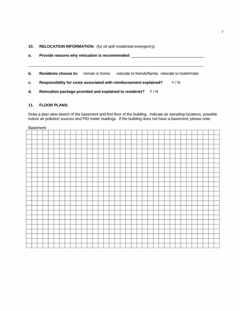
10. RELOCATION INFORMATION: (for oil spill residential emergency)
a. Provide reasons why relocation is recommended: __________________________________
__________________________________________________________________________________
b. Residents choose to: remain in home relocate to friends/family relocate to hotel/motel
c. Responsibility for costs associated with reimbursement explained? Y / N
d. Relocation package provided and explained to residents? Y / N
11. FLOOR PLANS:
Draw a plan view sketch of the basement and first floor of the building. Indicate air sampling locations, possible indoor air pollution sources and PID meter readings. If the building does not have a basement, please note.
Basement:

8
First Floor:

9
12. OUTDOOR PLOT:
Draw a sketch of the area surrounding the building being sampled. If applicable, provide information on spill locations, potential air contamination sources (industries, gas stations, repair shops, landfills, etc.), outdoor air sampling location(s), and PID meter readings.
Also indicate compass direction, wind direction and speed during sampling, the locations of the well and septic system, if applicable, and a qualifying statement to help locate the site on a topographic map.

10
13. PRODUCT INVENTORY FORM:
Make and Model of field instrument used: _________________________________________________ List specific products found in the residence or area that have the potential to affect indoor air quality (e.g., gasoline or kerosene storage cans, glues, paints, cleaning solvents/products, polishes/waxes, new furniture/ carpet, nail polish/hairspray/cologne).
Location Product Description Size (units) Condition* Chemical
Ingredients
Field Instrument
Reading (units)
Photo** Y/N