URD TCAI - GadgetOnline tcai install.pdfThis is an example of a TAP connection. Notice how the...
26
URD TCAI True Cold Air Intake 2005+ Tacoma 4.0 V6 Legal in California only for racing vehicles, which may never be used upon a highway.
Transcript of URD TCAI - GadgetOnline tcai install.pdfThis is an example of a TAP connection. Notice how the...

URD TCAI
True Cold Air Intake
2005+ Tacoma 4.0 V6
Legal in California only for racing vehicles, which may never be used upon a highway.

Underdog Racing Development www.URDUSA.com
Version 1.0 © URD 2007 2/8/07 Page 2 of 26 [email protected]
Introduction:
URD is proud of our TCAI (True Cold Air Intake System) for the 2005+ V6 Tacoma Trucks. URD tested many designs to ensure you are installing a superior True Cold Air Intake (TCAI).
There are many intake systems on the market called "Cold Air Intakes," but they are nothing of the sort. Our testing has shown that if you are drawing in air from inside the engine compartment you are not taking in cold air. It is just that simple.
URD found that inducting air from the grill area is about 30 degrees cooler than inducting air anywhere from under the hood. Another benefit when the vehicle speed increases is the dynamic air pressure increases and forces more air into the engine.
Another advantage of the TCAI placement is that it reduces induction noise inside of the cab. Make no mistake about it, the acoustics of this intake system at maximum RPM and wide-open throttle are very impressive, but the placement of the intake lessens the noise inside the vehicle. It will get the attention of those you are passing.
However, simply placing a filter in front of the truck does not make a good CAI. There are a number of subtle URD design attributes that are integrated into the TCAI to ensure a proper MAF Sensor reading.
Our TCAI uses the highest quality dry media air filter available. We chose the high end AMSOIL Nano Fiber intake filter with an internal forcing cone. This provides the best filtration available and there are no worries about the MAF sensor being contaminated with oil from other filter types.
URD's TCAI Systems are powder coated with a high quality black wrinkle finish and ship with all the required hardware and a very detailed, easy to follow installation manual. Installation will require removing a small section of sheet metal between the passenger headlight and radiator. This is easily done using an included template.
To extract the maximum benefit from the URD TCAI we recommend installation of our MAF Sensor Calibration Unit. This unit will electronically optimize fuel mixture for the greatest performance benefit. When you purchase the URD MAF Sensor Calibrator with the URD TCAI a special map will be preloaded into the Calibrator optimized for an otherwise stock vehicle. The Calibrator is end user tunable to compensate for other performance modifications you may have or may install in the future.

Underdog Racing Development www.URDUSA.com
Version 1.0 © URD 2007 2/8/07 Page 3 of 26 [email protected]
OPERATING LIMITATIONS: The location of the intake filter has been tested to function properly in heavy rain, snow and freezing rain. The only operating limitation is that the driver must never allow the intake filter to become submerged in deep water. Doing so will cause water to be drawn into the engine and could cause a cylinder hydro lock condition. That could result in permanent engine damage. If you plan on doing stream or deep-water crossings, this is not the intake system for you. The URD True Cold Air Intake is not CARB approved and is intended for off road / racing use only. Legal in California only for racing vehicles, which may never be used on the highway. Any questions, comments, or ideas, please mail URD Tech Support at [email protected] om.
Underdog Racing Development www.URDUSA.com
Version 1.0 © URD 2007 2/8/07 Page 4 of 26 [email protected]
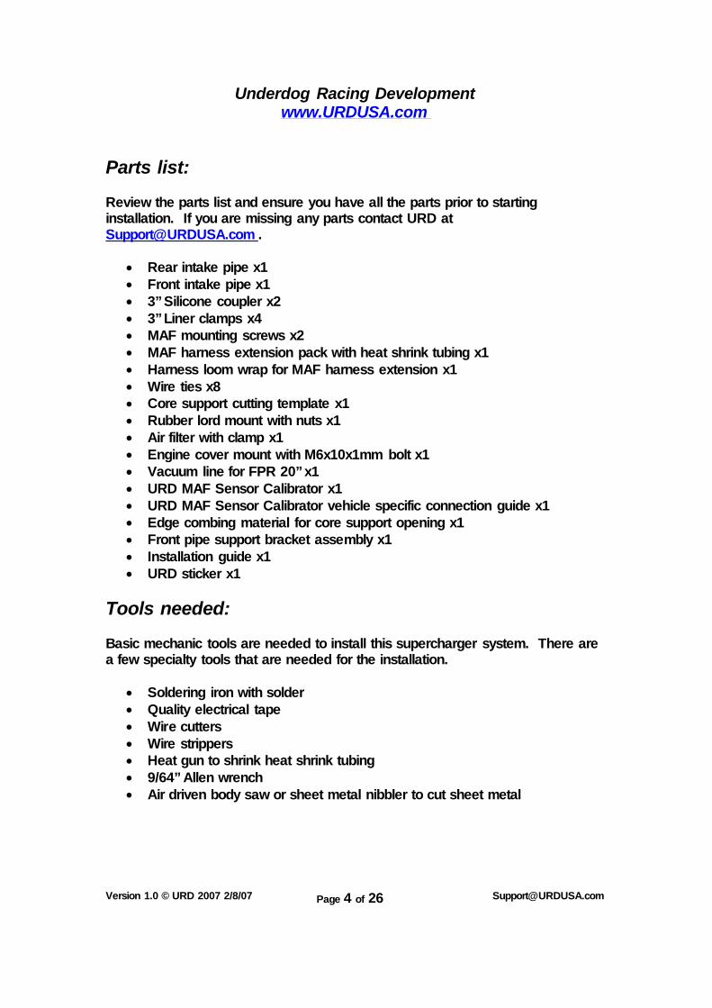
Parts list: Review the parts list and ensure you have all the parts prior to starting installation. If you are missing any parts contact URD at [email protected] .
Rear intake pipe x1 Front intake pipe x1 3” Silicone coupler x2 3” Liner clamps x4 MAF mounting screws x2 MAF harness extension pack with heat shrink tubing x1 Harness loom wrap for MAF harness extension x1 Wire ties x8 Core support cutting template x1 Rubber lord mount with nuts x1 Air filter with clamp x1 Engine cover mount with M6x10x1mm bolt x1 Vacuum line for FPR 20” x1 URD MAF Sensor Calibrator x1 URD MAF Sensor Calibrator vehicle specific connection guide x1 Edge combing material for core support opening x1 Front pipe support bracket assembly x1 Installation guide x1 URD sticker x1
Tools needed: Basic mechanic tools are needed to install this supercharger system. There are a few specialty tools that are needed for the installation.
Soldering iron with solder Quality electrical tape Wire cutters Wire strippers Heat gun to shrink heat shrink tubing 9/64” Allen wrench Air driven body saw or sheet metal nibbler to cut sheet metal

Underdog Racing Development www.URDUSA.com
Version 1.0 © URD 2007 2/8/07 Page 5 of 26 [email protected]
Prior to starting the installation, remove the negative battery terminal.
Cutting Hole for Intake:
1. Remove the Grill.
A. Open the hood. Remove two screws that attach the grill to the radiator core support near the hood latch.
B. Remove two plastic rivets. Use a flat bladed screwdriver to pop up
on the center of the rivet and pull the center up. This disengages the lock and you can now remove the whole rivet.
C. To unsnap the lower retainer clips, pull straight upward on the grill.
Underdog Racing Development www.URDUSA.com
Version 1.0 © URD 2007 2/8/07 Page 6 of 26 [email protected]
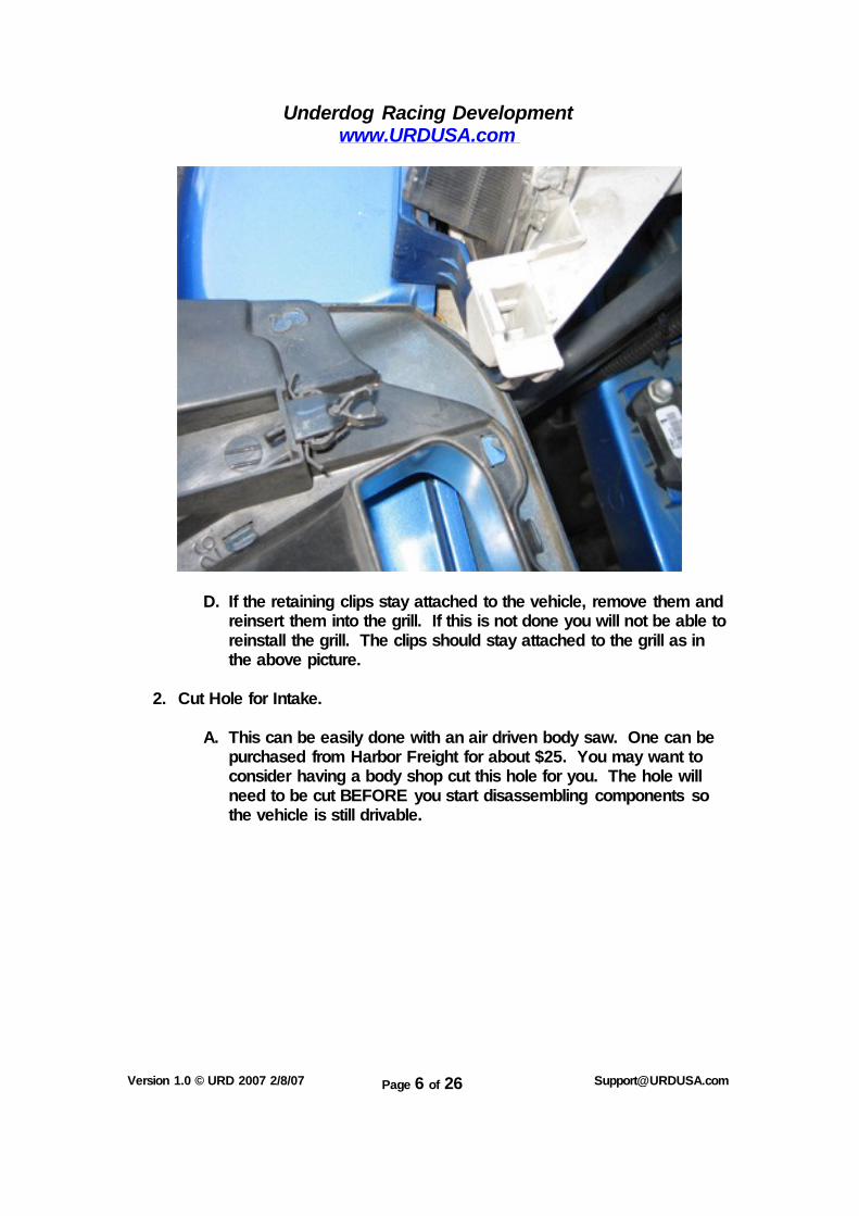
D. If the retaining clips stay attached to the vehicle, remove them and reinsert them into the grill. If this is not done you will not be able to reinstall the grill. The clips should stay attached to the grill as in the above picture.
2. Cut Hole for Intake.
A. This can be easily done with an air driven body saw. One can be
purchased from Harbor Freight for about $25. You may want to consider having a body shop cut this hole for you. The hole will need to be cut BEFORE you start disassembling components so the vehicle is still drivable.
Underdog Racing Development www.URDUSA.com
Version 1.0 © URD 2007 2/8/07 Page 7 of 26 [email protected]
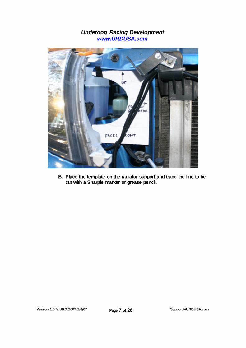
B. Place the template on the radiator support and trace the line to be
cut with a Sharpie marker or grease pencil.
Underdog Racing Development www.URDUSA.com
Version 1.0 © URD 2007 2/8/07 Page 8 of 26 [email protected]
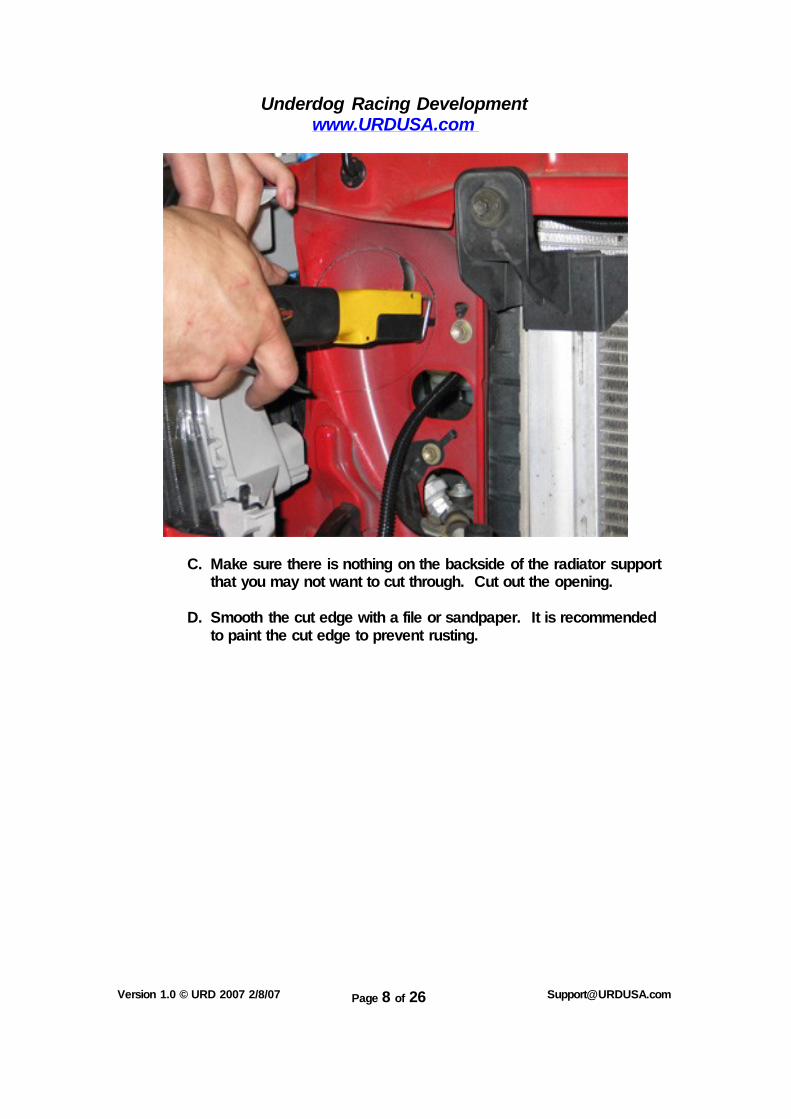
C. Make sure there is nothing on the backside of the radiator support that you may not want to cut through. Cut out the opening.
D. Smooth the cut edge with a file or sandpaper. It is recommended
to paint the cut edge to prevent rusting.
Underdog Racing Development www.URDUSA.com
Version 1.0 © URD 2007 2/8/07 Page 9 of 26 [email protected]
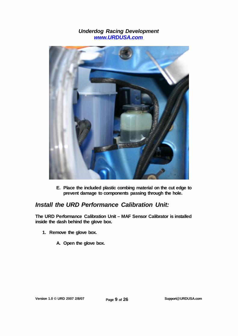
E. Place the included plastic combing material on the cut edge to prevent damage to components passing through the hole.
Install the URD Performance Calibration Unit: The URD Performance Calibration Unit – MAF Sensor Calibrator is installed inside the dash behind the glove box.
1. Remove the glove box.
A. Open the glove box.
Underdog Racing Development www.URDUSA.com
Version 1.0 © URD 2007 2/8/07 Page 10 of 26 [email protected]
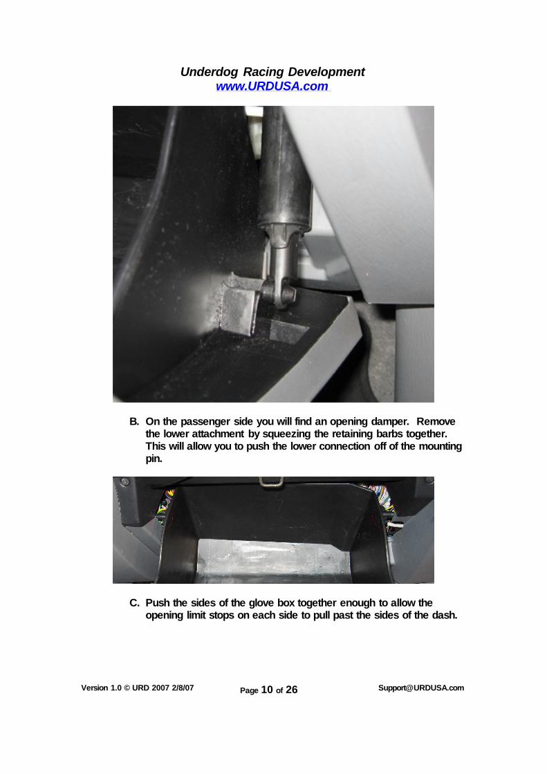
B. On the passenger side you will find an opening damper. Remove
the lower attachment by squeezing the retaining barbs together. This will allow you to push the lower connection off of the mounting pin.
C. Push the sides of the glove box together enough to allow the opening limit stops on each side to pull past the sides of the dash.

Underdog Racing Development www.URDUSA.com
Version 1.0 © URD 2007 2/8/07 Page 11 of 26 [email protected]
Note, the lower connection of the opening dampener should of already been removed and
not still attached as in this picture.
D. Continue to open the glove box just past the level plane. Now you
can pull straight back and detach the hinge points and free the glove box from the dash.

Underdog Racing Development www.URDUSA.com
Version 1.0 © URD 2007 2/8/07 Page 12 of 26 [email protected]
2. Locate the Engine Control Unit. It can be found sitting on its edge vertically on the far right with several large plugs.
3. Use the supplied vehicle specific connection guide and make the
necessary wiring connections to the ECU harness.
Underdog Racing Development www.URDUSA.com
Version 1.0 © URD 2007 2/8/07 Page 13 of 26 [email protected]
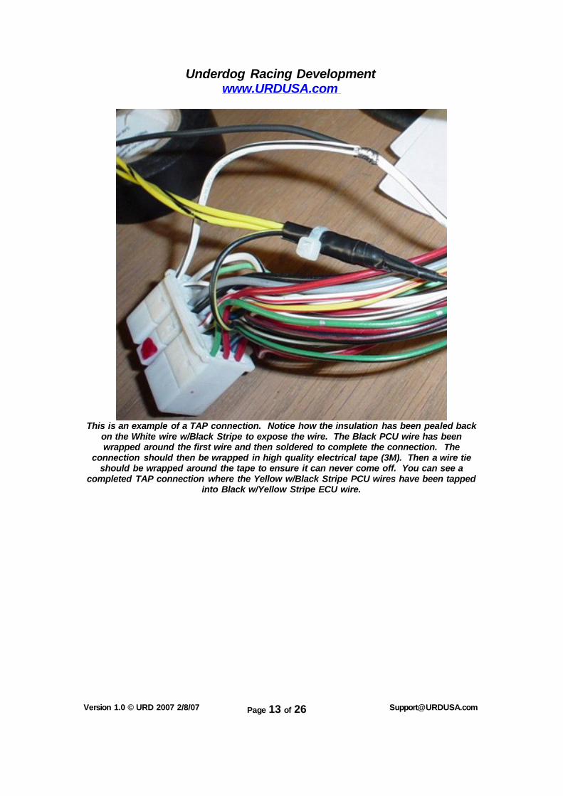
This is an example of a TAP connection. Notice how the insulation has been pealed back
on the White wire w/Black Stripe to expose the wire. The Black PCU wire has been wrapped around the first wire and then soldered to complete the connection. The
connection should then be wrapped in high quality electrical tape (3M). Then a wire tie should be wrapped around the tape to ensure it can never come off. You can see a
completed TAP connection where the Yellow w/Black Stripe PCU wires have been tapped into Black w/Yellow Stripe ECU wire.

Underdog Racing Development www.URDUSA.com
Version 1.0 © URD 2007 2/8/07 Page 14 of 26 [email protected]
This is an example of a splice connection. Note how the MAF signal wire has been cut.
That leaves two ends of the wire. That signal must be passed through the PCU to be modified. So in this picture the wire without the stripe is soldered to the signal wire and carries that signal into the PCU. The signal is modified and then comes out of the PCU
and is soldered to the wire going to the PCU plug. Each PCU and engine ECU is different. Follow the vehicle specific connection guide for your PCU and ECU to get the correct wire
color codes and plug and pin location.
A. All connections must be properly soldered. Crimp connectors are not recommended as they usually result in poor connections and serious performance problems.
B. After the wiring connections are completed, you can attach the unit
to the side of ECU with a large wire tie or double-sided tap.
Remove Stock Airbox:
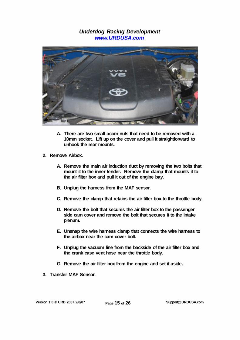
1. Remove Plastic Engine Cover.
Underdog Racing Development www.URDUSA.com
Version 1.0 © URD 2007 2/8/07 Page 15 of 26 [email protected]
A. There are two small acorn nuts that need to be removed with a 10mm socket. Lift up on the cover and pull it straightforward to unhook the rear mounts.
2. Remove Airbox.
A. Remove the main air induction duct by removing the two bolts that mount it to the inner fender. Remove the clamp that mounts it to the air filter box and pull it out of the engine bay.
B. Unplug the harness from the MAF sensor.
C. Remove the clamp that retains the air filter box to the throttle body.
D. Remove the bolt that secures the air filter box to the passenger
side cam cover and remove the bolt that secures it to the intake plenum.
E. Unsnap the wire harness clamp that connects the wire harness to
the airbox near the cam cover bolt.
F. Unplug the vacuum line from the backside of the air filter box and the crank case vent hose near the throttle body.
G. Remove the air filter box from the engine and set it aside.
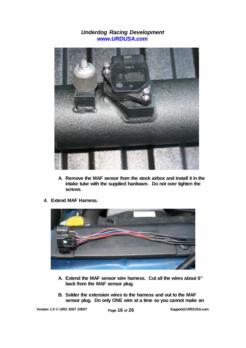
3. Transfer MAF Sensor.
Underdog Racing Development www.URDUSA.com
Version 1.0 © URD 2007 2/8/07 Page 16 of 26 [email protected]
A. Remove the MAF sensor from the stock airbox and install it in the intake tube with the supplied hardware. Do not over tighten the screws.
4. Extend MAF Harness.
A. Extend the MAF sensor wire harness. Cut all the wires about 6” back from the MAF sensor plug.
B. Solder the extension wires to the harness and out to the MAF
sensor plug. Do only ONE wire at a time so you cannot make an
Underdog Racing Development www.URDUSA.com
Version 1.0 © URD 2007 2/8/07 Page 17 of 26 [email protected]
incorrect connection. Slip the heat shrink tube over the wire and solder the extension wire to the harness wire on each and making sure you connect it to the same color code on each end. Use a heat gun to shrink the heat shrink tubing.
Install Piping:
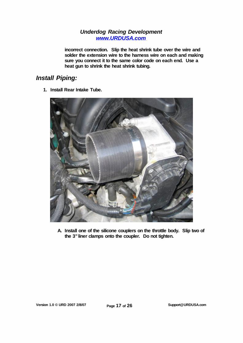
1. Install Rear Intake Tube.
A. Install one of the silicone couplers on the throttle body. Slip two of the 3” liner clamps onto the coupler. Do not tighten.
Underdog Racing Development www.URDUSA.com
Version 1.0 © URD 2007 2/8/07 Page 18 of 26 [email protected]
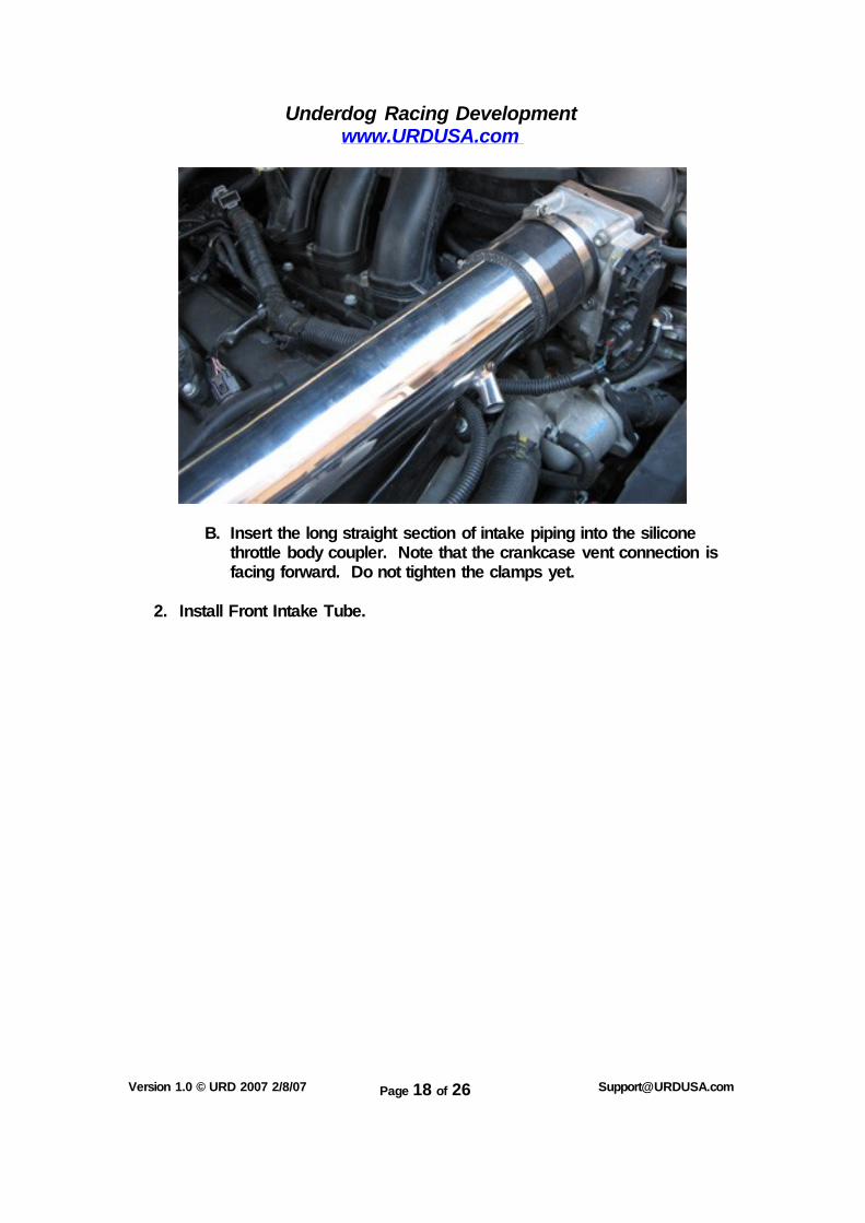
B. Insert the long straight section of intake piping into the silicone
throttle body coupler. Note that the crankcase vent connection is facing forward. Do not tighten the clamps yet.
2. Install Front Intake Tube.
Underdog Racing Development www.URDUSA.com
Version 1.0 © URD 2007 2/8/07 Page 19 of 26 [email protected]
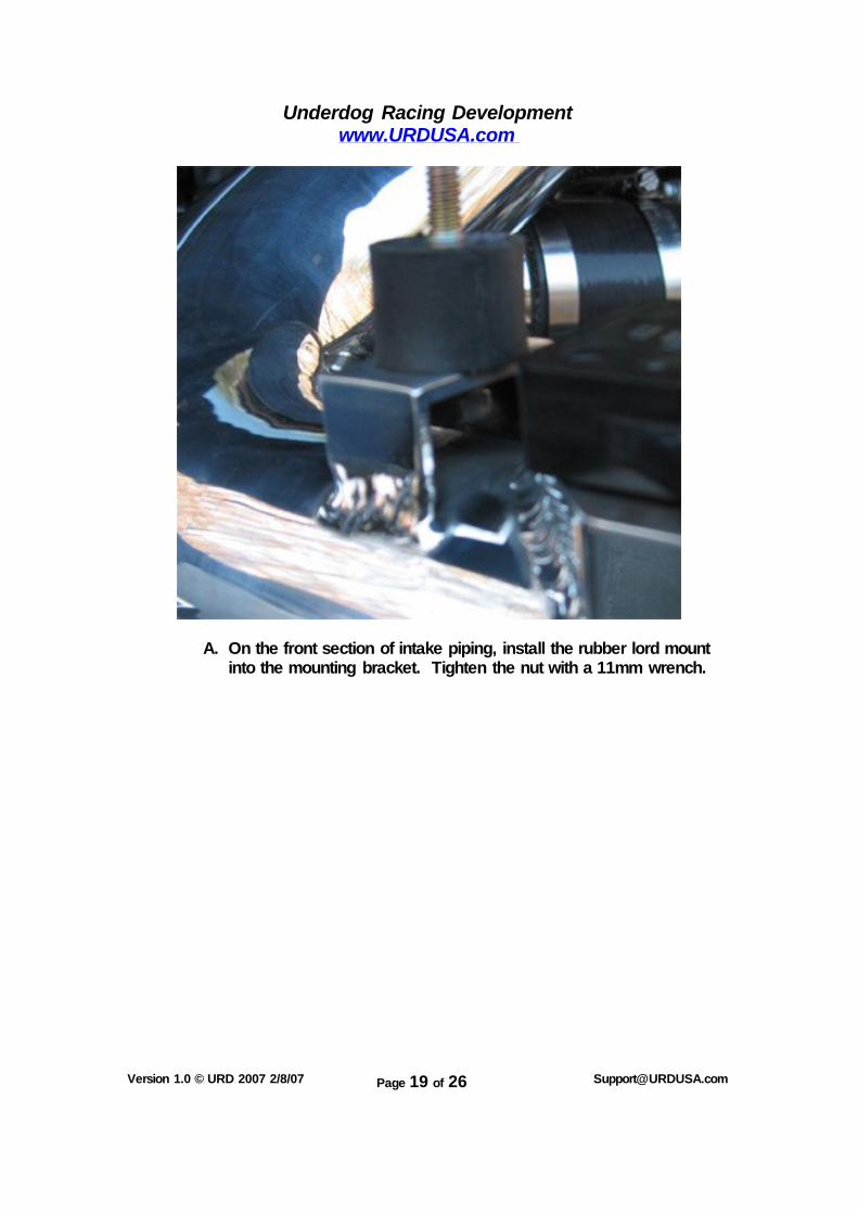
A. On the front section of intake piping, install the rubber lord mount into the mounting bracket. Tighten the nut with a 11mm wrench.
Underdog Racing Development www.URDUSA.com
Version 1.0 © URD 2007 2/8/07 Page 20 of 26 [email protected]
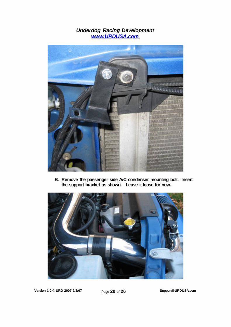
B. Remove the passenger side A/C condenser mounting bolt. Insert
the support bracket as shown. Leave it loose for now.
Underdog Racing Development www.URDUSA.com
Version 1.0 © URD 2007 2/8/07 Page 21 of 26 [email protected]
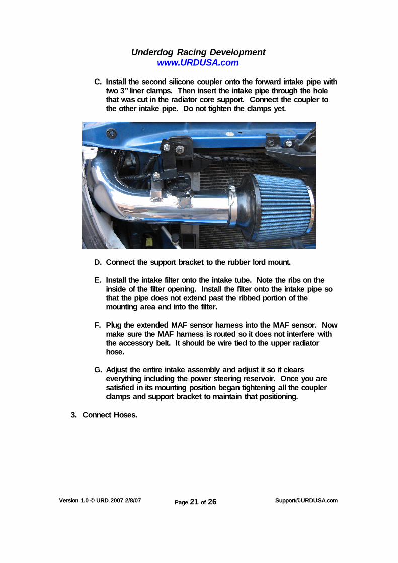
C. Install the second silicone coupler onto the forward intake pipe with two 3” liner clamps. Then insert the intake pipe through the hole that was cut in the radiator core support. Connect the coupler to the other intake pipe. Do not tighten the clamps yet.
D. Connect the support bracket to the rubber lord mount.
E. Install the intake filter onto the intake tube. Note the ribs on the inside of the filter opening. Install the filter onto the intake pipe so that the pipe does not extend past the ribbed portion of the mounting area and into the filter.
F. Plug the extended MAF sensor harness into the MAF sensor. Now
make sure the MAF harness is routed so it does not interfere with the accessory belt. It should be wire tied to the upper radiator hose.
G. Adjust the entire intake assembly and adjust it so it clears
everything including the power steering reservoir. Once you are satisfied in its mounting position began tightening all the coupler clamps and support bracket to maintain that positioning.
3. Connect Hoses.

Underdog Racing Development www.URDUSA.com
Version 1.0 © URD 2007 2/8/07 Page 22 of 26 [email protected]
A. Connect the crankcase vent hose to the forward vent nipple on the main intake pipe as shown.

Underdog Racing Development www.URDUSA.com
Version 1.0 © URD 2007 2/8/07 Page 23 of 26 [email protected]
B. Connect the provided vacuum line to the fuel pressure regulator as shown.
C. Connect the other end of the vacuum line to the smaller port on the rear side of the main intake tube.
Engine Cover:
1. Install Mounting Clamp.
Underdog Racing Development www.URDUSA.com
Version 1.0 © URD 2007 2/8/07 Page 24 of 26 [email protected]
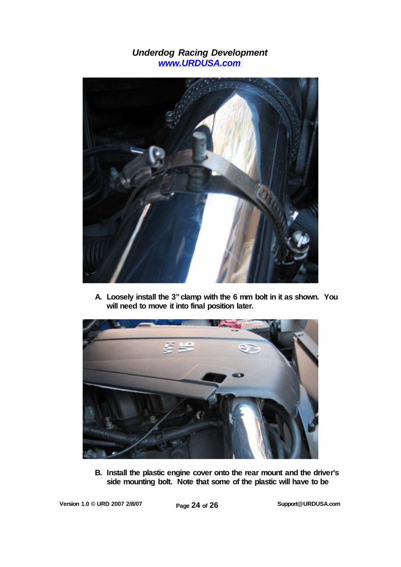
A. Loosely install the 3” clamp with the 6 mm bolt in it as shown. You will need to move it into final position later.
B. Install the plastic engine cover onto the rear mount and the driver’s
side mounting bolt. Note that some of the plastic will have to be
Underdog Racing Development www.URDUSA.com
Version 1.0 © URD 2007 2/8/07 Page 25 of 26 [email protected]
removed on the passenger side to allow the cover to sit down onto the intake system. You can use the same air saw or a rotary saw to clearance the material.
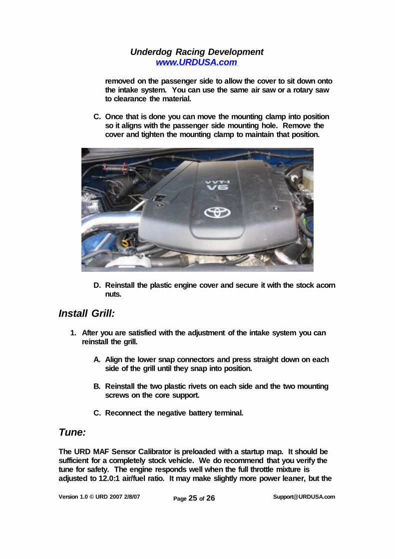
C. Once that is done you can move the mounting clamp into position
so it aligns with the passenger side mounting hole. Remove the cover and tighten the mounting clamp to maintain that position.
D. Reinstall the plastic engine cover and secure it with the stock acorn nuts.
Install Grill:
1. After you are satisfied with the adjustment of the intake system you can reinstall the grill.
A. Align the lower snap connectors and press straight down on each
side of the grill until they snap into position. B. Reinstall the two plastic rivets on each side and the two mounting
screws on the core support.
C. Reconnect the negative battery terminal.
Tune: The URD MAF Sensor Calibrator is preloaded with a startup map. It should be sufficient for a completely stock vehicle. We do recommend that you verify the tune for safety. The engine responds well when the full throttle mixture is adjusted to 12.0:1 air/fuel ratio. It may make slightly more power leaner, but the

Underdog Racing Development www.URDUSA.com
Version 1.0 © URD 2007 2/8/07 Page 26 of 26 [email protected]
exhaust gas temperature will start to rise very high. We feel that what little power is gained by going leaner is not worth the high temperatures. If you have other modifications, you should retune to compensate for your modifications. A detailed tuning guide is available from URD.