Uputstvo Za Ex1
132
3-280-015-11(1) Solid-State Memory Camcorder PMW-EX1 Operating Instructions © 2007 Sony Corporation
Transcript of Uputstvo Za Ex1

8/13/2019 Uputstvo Za Ex1
http://slidepdf.com/reader/full/uputstvo-za-ex1 1/132
3-280-015-11(1)
Solid-State MemoryCamcorder
PMW-EX1
Operating Instructions
© 2007 Sony Corporation

8/13/2019 Uputstvo Za Ex1
http://slidepdf.com/reader/full/uputstvo-za-ex1 2/132
2
For the customers in the U.S.A.This equipment has been tested and found to
comply with the limits for a Class A digitaldevice, pursuant to Part 15 of the FCC Rules.These limits are designed to providereasonable protection against harmfulinterference when the equipment is operated
in a commercial environment. Thisequipment generates, uses, and can radiateradio frequency energy and, if not installedand used in accordance with the instructionmanual, may cause harmful interference toradio communications. Operation of thisequipment in a residential area is likely to
cause harmful interference in which case theuser will be required to correct theinterference at his own expense.
You are cautioned that any changes ormodifications not expressly approved in this
manual could void your authority to operatethis equipment.
All interface cables used to connectperipherals must be shielded in order tocomply with the limits for a digital device
pursuant to Subpart B of Part 15 of FCCRules.
For the customers in EuropeThis product with the CE marking complieswith both the EMC Directive and the LowVoltage Directive issued by the Commissionof the European Community.
Compliance with these directives impliesconformity to the following Europeanstandards: EN60065 : Product Safety (AC adaptor)• EN55103-1 : Electromagnetic Interference
(Emission)
• EN55103-2 : Electromagnetic Susceptibility(Immunity)This product is intended for use in thefollowing Electromagnetic Environments:E1 (residential), E2 (commercial and lightindustrial), E3 (urban outdoors), E4
(controlled EMC environment, ex. TV studio)
The manufacturer of this product is SonyCorporation, 1-7-1 Konan, Minato-ku, Tokyo,Japan.
The Authorized Representative for EMC andproduct safety is Sony Deutschland GmbH,Hedelfinger Strasse 61, 70327 Stuttgart,Germany. For any service or guarantee
matters please refer to the addresses givenin separate service or guarantee documents.
For the State of California, USA onlyPerchlorate Material - special handling may
apply, See www.dtsc.ca.gov/ hazardouswaste/perchlorate
Perchlorate Material : Lithium batterycontains perchlorate.
For the customers in the USA and CanadaRECYCLING LITHIUM-ION BATTERIESLithium-Ion batteries are recyclable.You can help preserve our environment byreturning your used rechargeable batteries tothe collection and recycling location nearestyou.For more information regarding recycling of
rechargeable batteries, call toll free 1-800-822-8837, or visithttp://www.rbrc.org/ Caution: Do not handle damaged or leakingLithium-Ion batteries.
For the customers in Taiwan only

8/13/2019 Uputstvo Za Ex1
http://slidepdf.com/reader/full/uputstvo-za-ex1 3/132
Table of Contents 3
Overview
Package Configuration ............................................................. 8
Features ...................................................................................... 9
Using the CD-ROM ................................................................ 11
Reading the CD-ROM Manuals ................................... 11
System Requirements for Using the Applications ....... 12
Software Installation .................................................... 12
Parts Identifications ................................................................ 13
Camcorder .................................................................... 13
IR Remote Commander (Supplied) .............................. 17
On-Screen Indications ............................................................ 18
Indications in Camera Mode ........................................ 18
Direct Menu Operation ................................................ 19
Preparations
Power Supply ........................................................................... 21
Using a Battery Pack .................................................... 21
Using AC Power (DC IN Power) ................................. 22
Turning Power On ........................................................ 23
Turning Power Off ....................................................... 23
Setting the Clock ..................................................................... 23
Adjusting the LCD Monitor and Viewfinder ....................... 24
Adjusting the LCD Monitor ......................................... 24
Adjusting the Viewfinder ............................................. 25
Adjusting the Grip .................................................................. 27
Using the IR Remote Commander ........................................ 27
Handling SxS Memory Cards ................................................ 29
About SxS Memory Cards ........................................... 29
Inserting/Removing an SxS Memory Card .................. 30
Switching Between SxS Memory Cards ...................... 31
Formatting an SxS Memory Card ................................ 31
Checking the Remaining Time Available for
Recording ............................................................... 32
Restoring an SxS Memory Card .................................. 32
Table of Contents

8/13/2019 Uputstvo Za Ex1
http://slidepdf.com/reader/full/uputstvo-za-ex1 4/132
Table of Contents4
Recording
Basic Operation Procedure .................................................... 33
Selecting the Video Format .................................................... 35
Selectable Formats ....................................................... 35
Changing the Format .................................................... 36
Switching the ND Filters ........................................................ 36
Adjusting the White Balance ................................................. 37
Selecting the Adjustment Mode ................................... 37
Executing Auto White Balance .................................... 38
Displaying the Markers and Zebra Patterns ........................ 39
Displaying the Markers ................................................ 39
Displaying the Zebra Patterns ...................................... 40
Setting the Gain ....................................................................... 41
Recording With Fixed Gain ......................................... 41
Recording in AGC Mode ............................................. 41
Setting the Electronic Shutter ................................................ 42
Shooting in a Fixed Shutter Mode ............................... 42
Shooting in EX Slow Shutter Mode ............................. 43
Shooting in Auto Shutter Mode ................................... 43
Adjusting the Iris .................................................................... 44
Recording in Auto Iris Mode ....................................... 44
Adjusting the Iris Manually ......................................... 44
Adjusting the Zoom ................................................................ 45
Switching the Zoom Mode ........................................... 45
Operating the Zoom Manually ..................................... 45
Using the Power Zoom ................................................. 45
Adjusting the Focus ................................................................ 47
Adjusting in Full MF Mode ......................................... 47
Adjusting in MF Mode ................................................. 48
Adjusting in AF Mode ................................................. 49Using Macro Mode ...................................................... 49
Eliminating Picture Blurring (Steady Shot) ......................... 50
Reducing Flickers ................................................................... 50
Setting the Time Data ............................................................. 51
Running Modes of the Timecode ................................. 51
Setting the Timecode .................................................... 51
Setting the User Bits ..................................................... 52
Displaying the Time Data ............................................ 52
Recording Audio Signals ........................................................ 53
Using the Built-in Stereo Microphones ........................ 53
8/13/2019 Uputstvo Za Ex1
http://slidepdf.com/reader/full/uputstvo-za-ex1 5/132
Table of Contents 5
Using External Inputs ................................................... 53
Using an External Microphone .................................... 53
Adjusting the Audio Recording Levels ........................ 54
Monitoring the Audio ................................................... 54
Outputting the Color Bars and Reference Tone .................. 55
Recording Shot Marks ............................................................ 55
Rec Review ............................................................................... 56
Changing Functions of the Assignable Buttons ................... 56
Interval Recording .................................................................. 57
Preparatory Settings ..................................................... 57
Performing Interval Recording .................................... 58
Frame Recording .................................................................... 59
Preparatory Settings ..................................................... 59
Performing Frame Recording ....................................... 59Slow & Quick Motion Recording .......................................... 60
Preparatory Settings ..................................................... 60
Recording in Slow & Quick Motion Mode .................. 61
Freeze Mix: Image Alignment ............................................... 62
Shot Transition ........................................................................ 63
Preparatory Settings ..................................................... 64
Recording with a Shot Transition ................................ 65
Fader Function ........................................................................ 67
Preparatory Settings ..................................................... 67
Starting Recording with a Fade In ............................... 68
Ending Recording with a Fade Out .............................. 68
Picture Profiles ........................................................................ 69
Registering the Customized Settings as a Picture
Profile ..................................................................... 69
Selecting a Picture Profile ............................................ 69
Copying the Settings of a Picture Profile ..................... 70
Resetting a Picture Profile ............................................ 70
Picture Profile Items ..................................................... 71
Deleting Clips .......................................................................... 75
Deleting the Last Recorded Clip .................................. 75
Deleting All Clips ........................................................ 75
Storing/Retrieving the Setting Data ...................................... 76
Storing the Setup File ................................................... 76
Retrieving the Setup File .............................................. 76
Resetting to the Standard Values ................................. 76

8/13/2019 Uputstvo Za Ex1
http://slidepdf.com/reader/full/uputstvo-za-ex1 6/132
Table of Contents6
Playback
Playing Back Clips .................................................................. 77
Thumbnail Screen ........................................................ 77
Playback ....................................................................... 78
Clip Operations ....................................................................... 81
Clip Operation Menus .................................................. 81
Basic Operations of the Clip Operation Menus ........... 82
Displaying the Detailed Information of a Clip ............. 83
Adding the OK Mark to a Clip ..................................... 83
Copying a Clip ............................................................. 84
Deleting a Clip ............................................................. 84
Displaying the EXPAND CLIP Screen ........................ 84
Displaying the SHOT MARK Screen .......................... 85
Adding/Deleting Shot Marks ....................................... 86
Changing the Index Frame ........................................... 87Dividing a Clip ............................................................. 87
Status Displays
Showing the Status Screens .................................................... 88
CAMERA Status Screen ........................................................ 89
AUDIO Status Screen ............................................................. 90
In Camera Mode ........................................................... 90In Media Mode ............................................................. 90
VIDEO Status Screen ............................................................. 91
BUTTON/REMOTE Status Screen ...................................... 91
BATTERY/MEDIA Status Screen ........................................ 92
Menu Configuration and Detailed Settings
Overview of the Setup Menus ................................................ 93
Setup Menu Configuration ........................................... 93
Setup Menu Layers ...................................................... 93
Basic Menu Operations .......................................................... 94
Setup Menu List ...................................................................... 97
CAMERA SET Menu .................................................. 97
AUDIO SET Menu .................................................... 101
VIDEO SET Menu ..................................................... 102
LCD/VF SET Menu ................................................... 103TC/UB SET Menu ...................................................... 105
OTHERS Menu .......................................................... 105

8/13/2019 Uputstvo Za Ex1
http://slidepdf.com/reader/full/uputstvo-za-ex1 7/132
Table of Contents 7
Connecting External Devices
Connecting External Monitors ............................................ 109
Operating Clips With a Computer ...................................... 110
Connecting an External Device (i.LINK Connection) ....... 113
Recording the Camcorder Picture on an ExternalDevice .................................................................. 113
Nonlinear Editing ....................................................... 113
Recording External Input Signals .............................. 114
Appendixes
Important Notes on Operation ............................................ 115
Formats and Limitations of Outputs .................................. 116
Video Formats and Output Formats ........................... 116
Limitations of Outputs ............................................... 117
Backup Battery ..................................................................... 118
Troubleshooting .................................................................... 119
Operating Power ......................................................... 119
Recording/Playback ................................................... 119
External Devices ........................................................ 120
Error/Warning Indications .................................................. 121
Error Indications ......................................................... 121Warning Indications ................................................... 121
About i.LINK ........................................................................ 123
Specifications ......................................................................... 124
General ....................................................................... 124
Camera Block ............................................................. 124
Audio Block ............................................................... 125
Displays ...................................................................... 125
Inputs/Outputs ............................................................ 125
Optional Accessories .................................................. 126
Index ....................................................................................... 128

8/13/2019 Uputstvo Za Ex1
http://slidepdf.com/reader/full/uputstvo-za-ex1 8/132
Package Configuration8
Ov er v i ew
Make sure you have following items supplied with your camcorder.
The number in parentheses indicates the number of that item supplied.
Overview
Package Configuration
Lens hood with lens cap (1)
It is attached to the camcorder at the factory.
If you attach an optional wide-conversion lens,
remove the lens hood.
Large eyecup (1)
It is attached to the
camcorder at the factory.
Infrared Remote
Commander (1)
USB cable (1)
AV connecting cable (1)
Component video cable (1)
1
2
ZOOM
PUSH SET
SHOTMARK
THUMBNAIL
PLAY/PAUSE STOP
W
.
m
z
>
M
X
xu
T
SUB CLIP
PUSHAFRECPAUSEREC
FFWDFREV
PREV NEXT
BP-U30 battery pack (1)
BC-U1 battery charger (1)
Shoulder strap (1)
Lithium battery (CR2032 for backup) (1)
It is mounted in the camcorder at the factory.
Lithium battery (CR2025 for the IR Remote
Commander) (1)
It is mounted in the IR Remote Commander at the
factory.
CD-ROM (1)XDCAM EX Clip Browsing Software, SxS Device
Driver Software, Operating Instructions in PDF
format are included.
Operating Instructions (This manual) (1)
SxS Device Driver Software End-User
License Agreement (1)
B P - S 3 0
D C O U T C H AR G E
B AT T E R Y C H AR G E R
B C - U 1
0 %
8 0 1 0 0

8/13/2019 Uputstvo Za Ex1
http://slidepdf.com/reader/full/uputstvo-za-ex1 9/132
Features 9
Ov er v i ew
The PMW-EX1 is a highly compact and high-
performance XDCAM EX1) camcorder that usesSxS1) memory cards, as its recording medium.
The imaging devices used in the PMW-EX1
camcorder are three 1 / 2-inch type CMOS sensors,
each with an effective pixel count of 1920 × 1080,
which produce images in full HD resolution.
A New Generation of HD RecordingSystem
New nonlinear recording mediaUsing SxS memory cards, the PMW-EX1 offers
nonlinear capabilities such as instant random
access and file-based operation.
HD recording using the “MPEG-2 Long GOP”
codec
The PMW-EX1 records 1920 × 1080 HD images
using “MPEG-2 Long GOP” codec compression.
This mature “MPEG-2 Long GOP” codec, which
is also adopted in the XDCAM1) HD and HDV2)
1080i series of products, enables you to record
stunning-quality HD video and audio with long
recording time by efficiently compressing the
data.
Selectable bit rates
The PMW-EX1 offers a choice of bit rates: either
35 Mbps (HQ mode) or 25 Mbps (SP mode),
depending on the desired picture quality and
recording time.
Long recording time
By utilizing an efficient compression format, thePMW-EX1 records high-quality HD images for
long recording time of approx. 50 minutes in HQ
mode (35 Mbps VBR) or approx. 70 minutes in
SP mode (25 Mbps CBR) on a single 16-GB SxS
memory card. Equipped with two SxS memory
card slots, the PMW-EX1 makes transition
seamless without any frame loss, when recording
is done across two cards,
Multiple-format recording
The PMW-EX1 camcorder offers a wide array ofrecording formats for multiple content creation
applications. The scanning mode is switchable
among 1920 × 1080, 1280 × 720, and 1440 ×
1080 resolutions. Frame rate is also selectable
from interlace and progressive (59.94i, 50i,
29.97P, 25P, and native 23.98P). In addition,
59.94P and 50P progressive recording is available
in 1280 × 720 mode. SxS memory cards can
simultaneously hold multiple files of any of these
recording formats, allowing for flexible use of the
memory cards.
High-quality uncompressed audio recording
In addition to HD video recording, the PMW-
EX1 can record and play back high-quality, two-
channel 16-bit, 48-kHz linear PCM
uncompressed audio.
IT friendly
The file-based recording in MP4 format allows
material to be handled with great flexibility in an
IT-based environment, easily available for
copying, transferring, sharing, and archiving.
For immediate recording start
In recording on flash memory cards, the XDCAM
EX system makes each new recording on an
empty area of the card. This is extremely
convenient, as the camera operator need not
worry about accidentally recording over good
takes or search through footage for the correct
position to start the next recording.
Instant-access thumbnail display with “Expand”function
Each time a recording is started and stopped on
the XDCAM EX camcorder, the video and audio
signals are recorded as one clip.
Furthermore, thumbnails are automatically
generated for each clip as a visual reference,
allowing the operator to cue-up to a desired scene
simply by guiding the cursor to a thumbnail. For
further convenience, the ‘Expand’ function
allows one selected clip in the Thumbnail display
to be divided into 12 equal time intervals, each
with its own thumbnail identifier. This is useful if
you wish to quickly search for a particular scene
within a lengthy clip.
Cutting-edge Camera Technologies
1 / 2-inch type three “Exmor”1) CMOS sensors
The PMW-EX1 is equipped with three newly
developed 1 / 2-inch type “Exmor” CMOS
Sensors, which deliver excellent pictureperformance with full HD resolution.
Features

8/13/2019 Uputstvo Za Ex1
http://slidepdf.com/reader/full/uputstvo-za-ex1 10/132
Features10
Ov er v i ew
14x zoom lens
The PMW-EX1 is equipped with a zoom lens
specifically designed for the camcorder to offer
optimum picture performance. Independent rings
for zoom, focus, and iris adjustment give the user
a high level of operational comfort.
Versatile focus-assistance functions
The lens has a versatile functions for easy and
precise focus adjustments.
• One-push Auto Focus
• MF Assist
• Expanded Focus
• Peaking
• Optical Image Stabilizer (Steady Shot)
Creative Recording Modes and Settings
23.98P native recordingThe PMW-EX1 camcorder, a new member of
Sony’s legendary CineAlta1) family, though
compact offers native 23.98P recording
capability.
Slow & Quick Motion function
The PMW-EX1 offers a Slow & Quick Motion
function, commonly known as overcranking and
undercranking in film shooting, which enables
you to create unique ‘looks’ or special effects of
slow- and fast-motion images.
Slow Shutter function
The PMW-EX1 offers a Slow Shutter function for
capturing clear images in low-light environments.
This allows the shutter speed to be changed to a
maximum of 64-frame accumulation period.
Selectable gamma curves
The PMW-EX1 provides various types of gamma
identical to those of other CineAlta camcorders.
Interval Recording functionThe PMW-EX1 offers an Interval Recording
function that intermittently records signals at pre-
determined intervals. This is convenient for
shooting over long periods of time and also when
creating pictures with special effects of extremely
quick motion.
Frame Recording function
Frame Recording is a unique feature of the PMW-
EX1 camcorder that is especially useful for clay-
animation shooting. With this function, images
for pre-determined frame are recorded each time
the record button is pressed.
Shutter-angle settings
In addition to the electric shutter speed controls,
the PMW-EX1 also has a “shutter angle” control,
which is familiar to cinematographers.
Picture Profile feature
The Picture Profile feature allows the camera
operator to easily call up customized picture-
tonal settings to suit particular shooting
conditions.
Shot Transition function
The Shot Transition function allows for smooth
automatic scene transitions. The operator can
program start and end settings for zoom, focus,
and white balance into the A and B buttons, and
with a press of the Start button a smooth transition
will take place according to the set time.
A variety of functions and designs forhigh operability
• Depth-of-field indicator
• Brightness-level display
• Histogram indicator
• 3.5-inch color LCD monitor
• Easy-to-see color viewfinder
• Rotary grip
• Four assignable buttons
• Zoom and recording start/stop operationsenabled both on the handle and the grip
• Long operating time with a battery pack
• Wide array of interfaces, including USB and
i.LINK1)
• ATW (Auto Tracing White Balance)
• Built-in ND filter wheel
• Selectable gain
• High-speed picture search: ×4, ×15
• Freeze Mix function
• IR Remote Commander1) supplied
1) Sony, XDCAM, XDCAM EX, SxS, i.LINK, Exmor,
CineAlta, and Remote Commander are trademarks of
Sony Corporation.
2) HDV is a trademark of Sony Corporation and Victor
Company of Japan, Limited.
All other trademarks are the property of their respective
owners.

8/13/2019 Uputstvo Za Ex1
http://slidepdf.com/reader/full/uputstvo-za-ex1 11/132
Using the CD-ROM 11
Ov er v i ew
XDCAM EX web sites
For information on XDCAM EX, visit the
following web sites:
United States
http://www.sony.com/xdcamex
Canadahttp://www.sony.ca/xdcamex
Europe, Middle East, Africa, and Russia
http://www.sonybiz.net/xdcamex
Latin America
http://www.sonypro-latin.com/xdcamex
Australia
www.sony.com.au/xdcamex
Asia (except Korea, China, and Japan)
http://pro.sony.com.hk
Korea
http://bp.sony.co.kr/xdcamex
China
http://pro.sony.com.cn/minisite/XDCAMEX
Japan
http://www.sony.co.jp/XDCAMEX
The supplied CD-ROM includes the following
files:
PMW-EX1 Operating Instructions
The Operating Instructions for the PMW-EX1
(Japanese, English, French, German, Italian,
Spanish and Chinese) are provided in PDF
format.
SxS Device Driver Software
Driver for using SxS memory cards with a
computer having an ExpressCard slot.
Information on installation of the software is
included in the ReadMe (Japanese, English,
French, German, Italian, Spanish, and Chinese) in
PDF format.
XDCAM EX Clip Browsing Software
Application program for operating clips recorded
with XDCAM EX-series models on a computer.
Information on installation and operations of the
software is included in the User’s Guide
(Japanese, English, French, German, Italian,
Spanish, and Chinese) in PDF format.
Preparations
The following program must be installed on your
computer in order to read the operation manuals
contained on the CD-ROM.
Adobe Reader Version 6.0 or higher
Memo
If Adobe Reader is not installed, you can
download it from the following URL:
http://www.adobe.com/
Adobe and Adobe Reader are trademarks of Adobe
Systems Incorporated in the United States and/or other
countries.
To read the documents
Do the following:
1 Insert the CD-ROM in your CD-ROM
drive.
Using the CD-ROM
Reading the CD-ROM Manuals

8/13/2019 Uputstvo Za Ex1
http://slidepdf.com/reader/full/uputstvo-za-ex1 12/132
Using the CD-ROM12
Ov er v i ew
A cover page appears automatically in your
browser.
If it does not appear automatically in the
browser, double-click on the index.htm file
on the CD-ROM.
2 Select and click on the manual that you
wish to read.This opens the PDF file.
Memo
The files may not be displayed properly,
depending on the version of Adobe Reader. In
such a case, install the latest version you can
download from the URL mentioned in
“Preparations” above.
Note
If you have lost or damaged the CD-ROM, you
can purchase a new one to replace it. Contact your
Sony service representative.
The following operating conditions are
recommended for using the software recorded on
the CD-ROM:
SxS Device Driver Software
Applicable hardware
Computer conforming to ExpressCard/34 or
ExpressCard/54
OS
Microsoft Windows XP SP2 or later, Microsoft
Windows Vista, or Mac OS X v10.4.9 or later
For support information on the driver, refer to the
following URL:
http://www.sony.net/SxS-Support/
XDCAM EX Clip Browsing Software
OS
Microsoft Windows XP SP2 or later (32-bit
version), Microsoft Windows Vista (32-bit
version), or Mac OS X v10.4.10
CPU
Windows: Intel Pentium III 1GHz equivalent or
higher (Intel PentiumD 3GHz equivalent or
higher is recommended)
Macintosh: Intel Core 2 Duo 2GHz or higher is
recommended
Memory
Windows: 512 MB or more (1 GB or more is
recommended)
Macintosh: 1 GB or more is recommended
• Microsoft, Windows, and Windows Vista are
registered trademarks and/or trademarks of Microsoft
Corporation in the United States and/or other
countries.
• Intel Core and Pentium are trademarks of Intel
Corporation in the United States and/or other
countries.
• Macintosh and Mac OS are trademarks of Apple Inc.
registered in the U.S States and other countries.
Do the following to install the software on the
CD-ROM on your computer:
1 Insert the CD-ROM in your CD-ROM
drive.
A cover page appears automatically in your
browser.
If it does not appear automatically in the
browser, double-click on the index.htm file
on the CD-ROM.
2 Select and click on the software that you
wish to install.
The installer for the software starts up.
Follow the displayed instructions:
For details, refer to the User’s Guide or ReadMe of
the software.
Uninstalling an application program
Windows computer
Choose “Start,” “Control Panel” then “Add or
Remove Programs” and specify the program to be
deleted.
Macintosh computer
Drop the folder of the software (default:
/Application/XDCAM EX Clip Browser) into
Trash.
System Requirements for Usingthe Applications
Software Installation

8/13/2019 Uputstvo Za Ex1
http://slidepdf.com/reader/full/uputstvo-za-ex1 13/132

8/13/2019 Uputstvo Za Ex1
http://slidepdf.com/reader/full/uputstvo-za-ex1 14/132
Parts Identifications14
Ov er v i ew
8. Viewfinder (page 25)
9. Eyecup (page 25)
10. Eyepiece focusing knob (page 25)
11. Headphone jack (stereo mini jack) ( page 54, page 80)
12. i.LINK (HDV) connector (4-pin, S400
conforming to IEEE1394) (page 113)
13. Hooks for the shoulder strap (left and
right)
Attach the supplied shoulder strap as shown
below.
14. Built-in speaker ( page 54, page 80)
15. Grip (page 27)
16. BATTERY RELEASE button (page 21)
17. SDI OUT connector (BNC type) (page 109)
18. A/V OUT connector (audio/video multi
output) (page 110)
19. COMPONENT OUT connector (Mini D)
(page 109)
20. USB connector (Mini B) (page 110)
21. Accessory shoe22. REC/TALLY lamp ( page 34, page 121)
23. IR remote control receptor
24. AUDIO IN CH-1/CH-2 connectors (XLR)
and input selection switches (page 53)
25. WHT BAL (automatic white balance
adjustment) button (page 37)
26. SHUTTER switch (page 42)
27. ASSIGN 4 (assignable 4) button (page 56)
For functions and usage, see the pages shown in
parentheses.
Note
The lens is properly adjusted at the factory. Do
not touch the controls of the lens control block.
BATTERYRELEASE
SDI OUTA / V OUT
E X P A N D E D
F O C U
S
R E C
R E V I E W
R E L E A S E
S T A R T /
S T O P
A
S H O T
T R A N S I T I O N B
L C D B . L I G
H T T C / U - B I T /
D U R A T I O N S T A T U S
B A R S / C A M
D I S P L A Y B A T T I N F O
O N
O F F
P R E V
P L A Y / P A U
S E
S T O P
C A N
C E L
F F W
D
N E X T
R E C
S T A R T / S
T O P
H O L D
l
s L
j
G / S
J
H L O F F
T H U M
B N A I L
F R E V
S E L / S E
T
M O N I T O
R V O
L
A U D I O I N
C H - 1
M I C L I N E M I C + 4 8 V M I C L I N E
M I C + 4 8 V
C H - 2
A/V OUTCOMPONENT
OUT
ASSIGN 4 OFF ON
SHUTTER
WHT BAL
Controls on the grip(page 17)
Inside the cover
8
9
10
111213141516
17
18
19
20
21
22
23
24
25
26
27
13
Cover of the lenscontrol block (See
“Note” below.)
1
2
3 4
8/13/2019 Uputstvo Za Ex1
http://slidepdf.com/reader/full/uputstvo-za-ex1 15/132
Parts Identifications 15
Ov er v i ew
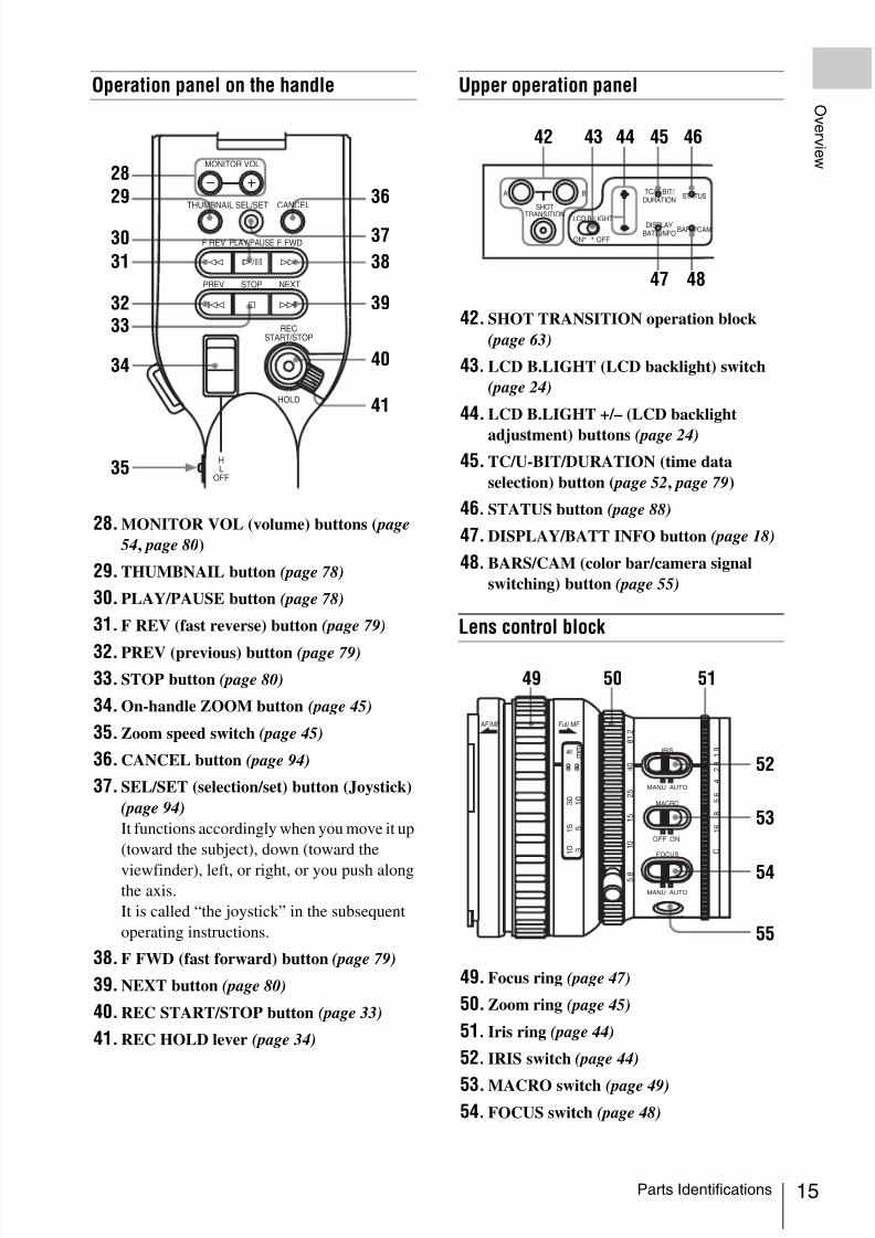
Operation panel on the handle
28. MONITOR VOL (volume) buttons ( page
54, page 80)
29. THUMBNAIL button (page 78)
30. PLAY/PAUSE button (page 78)
31. F REV (fast reverse) button (page 79)
32. PREV (previous) button (page 79)
33. STOP button (page 80)
34. On-handle ZOOM button (page 45)
35. Zoom speed switch (page 45)
36. CANCEL button (page 94)
37. SEL/SET (selection/set) button (Joystick)
(page 94)
It functions accordingly when you move it up
(toward the subject), down (toward the
viewfinder), left, or right, or you push alongthe axis.
It is called “the joystick” in the subsequent
operating instructions.
38. F FWD (fast forward) button (page 79)
39. NEXT button (page 80)
40. REC START/STOP button (page 33)
41. REC HOLD lever (page 34)
Upper operation panel
42. SHOT TRANSITION operation block
(page 63)
43. LCD B.LIGHT (LCD backlight) switch
(page 24)
44. LCD B.LIGHT +/– (LCD backlight
adjustment) buttons (page 24)
45. TC/U-BIT/DURATION (time data
selection) button ( page 52, page 79)
46. STATUS button (page 88)
47. DISPLAY/BATT INFO button (page 18)
48. BARS/CAM (color bar/camera signal
switching) button (page 55)
Lens control block
49. Focus ring (page 47)
50. Zoom ring (page 45)
51. Iris ring (page 44)
52. IRIS switch (page 44)
53. MACRO switch (page 49)
54. FOCUS switch (page 48)
THUMBNAIL
F REV
PREV
SEL/SET
PLAY/PAUSE
STOP
CANCEL
F FWD
NEXT
REC
START/STOP
HOLD
l s L
j G / S J
MONITOR VOL
H
L
OFF
36
37
38
39
40
41
28
29
30
31
3233
34
35
A
SHOT
TRANSITION
B
LCD B.LIGHT
TC/U-BIT/
DURATION STATUS
BARS/CAMDISPLAY
BATT INFOON OFF
42 43 44 45 46
47 48
AF/MF Full MF
1 5
2 5
4 0
8 1 . 2
1 0
3
1 0
m m
5
1 0
3 0
f t
1 5
5 . 8
C
MANU AUTO
MANU AUTO
MACRO
FOCUS
PUSH AF
IRIS
OFF ON
8
5 . 6
4
2 . 8
1 . 9
1 6
49 50 51
52
53
54
55

8/13/2019 Uputstvo Za Ex1
http://slidepdf.com/reader/full/uputstvo-za-ex1 16/132
Parts Identifications16
Ov er v i ew
55. PUSH AF (momentary auto focus) button
(page 48)
Side operation panel
56. ND filter select switch (page 36)
57. ASSIGN (assignable)1/2/3 buttons (page
56)
58. PEAKING button (page 48)
59. FULL AUTO button and indicator (page
33)
60. ZEBRA button (page 40)
61. WHITE BAL (white balance memory)
switch (page 37)
62. GAIN switch (page 41)
Card slot block
The SxS memory card slots and EJECT buttons
are located behind the cover.
63. ACCESS lamps (page 30)
64. SLOT SELECT (SxS memory card select)
button (page 31)
65. SxS memory card slots (page 30)
66. EJECT buttons (page 30)
Rear operation panel
67. MENU (menu display ON/OFF) button
(page 94)
68. SEL/SET (selection/set) dial (Jog dial)
(page 94)
It functions accordingly when you turn it up
or down, or you push it horizontally.
It is called “the jog dial” in the subsequentoperating instructions.
69. CANCEL button (page 94)
70. PICTURE PROFILE button (page 69)
71. Power (CAMERA/MEDIA) switch (page
23)
72. DC IN (DC power input) connector (page
22)
73. AUDIO LEVEL CH-1 /CH-2 controls
(page 53)
74. AUDIO SELECT (audio level control
mode selection) switches (page 53)
75. AUDIO IN (audio input selection)
switches (page 53)
ZEBRA PEAKING
GAINOFF
2
1
ND
FILTER
BA
PRST
LM
H
WHITE BAL
FULL AUTO
1 2 3
ASSIGN
LENS INFO BRT DISP HISTOGRAM
56
57
58
59
60
61
62
SLOT SELECT
CH-1
AUDIO
LEVEL
CH-2
A B
OPEN
ACCESS
63
64
65
66
AUTO
MANUAL
INT
EXT
PICTURE
PROFILE
PMW-EX1
DC IN
CH-2
AUTO
MANUAL
INT
EXTCH-1
AUDIO
SELECT
AUDIO
IN
OFFCAMERACANCELSEL/SET MEDIA
BATTERYRELEASE
MENU
CH-1
AUDIO
LEVEL
CH-2
67 68 69 70 71 72
73 74 75

8/13/2019 Uputstvo Za Ex1
http://slidepdf.com/reader/full/uputstvo-za-ex1 17/132
Parts Identifications 17
Ov er v i ew
Controls on the grip
76. REC START/STOP button (page 33)
77. RELEASE (grip release) button (page 27)
78. REC REVIEW button (page 56)
79. EXPANDED FOCUS button (page 47)
80. Servo zoom lever (page 45)
81. LENS REMOTE connector (page 46)
Bottom
82. ZOOM switch (page 45)
83. Tripod receptacle
Check that the size of the hole matches the
screw of the tripod. If they do not match, the
camcorder cannot be attached to the tripod
securely.
84. Backup battery holder (page 118)
The buttons without remarks can be used in the
same manner as the corresponding buttons on the
camcorder.
1. ZOOM T/W (telephoto/wide-angle)
button
2. SHOTMARK 1 and 2 buttons ( page 55,
page 86 )
3. THUMBNAIL button
4. PREV (previous clip jump) button
5. F REV (fast reverse) button
6. PLAY/PAUSE button
7. REC (record) buttons
Press the z button together with the unmarked
button (safety button) to start recording.
8. REC PAUSE buttons
Press the X button together with the unmarked
button (safety button) to pause recording.
9. PUSH SET button (four-way arrow key)
It functions the same as the SEL/SET button
(joystick) on the camcorder.
10. NEXT button
11. STOP button
12. F FWD (fast forward) button
13. PUSH AF button
Note
The SUB CLIP button does not function with this
camcorder.
When you use the remote commander, see “Using the
IR Remote Commander” on page 27 .
Note
OMPONENTOUT
E X P A N
D E D
F O C U
S
R E C
R E V I E W
R E L E A S E
S T A R T /
S T O P
LENS
REMOTE
81
76
77
78
79
80
MANU AUTO
FOCUS
M A N U S E R V O
Z O O M
PUSH AF
M A N U S E R V O
Z O O M
82 83 84
IR Remote Commander (Supplied)
1
2
T
ZOOM
PUSH SET
SHOTMARK
SUB CLIPTHUMBNAIL
PLAY/PAUSE STOP
PUSHAFRECPAUSEREC
W
.
m
z
>
M
X
xu
FFWDFREV
PREV NEXT
12
3456
7
8
9
10
11
12
13

8/13/2019 Uputstvo Za Ex1
http://slidepdf.com/reader/full/uputstvo-za-ex1 18/132
On-Screen Indications18
Ov er v i ew
When this unit is in Camera mode (mode for
recording), pressing the DISPLAY/BATT INFO
button displays the statuses and settings of this
unit on the LCD monitor/viewfinder screen.
When you press the DISPLAY/BATT INFO
button again, these indications are canceled.
Remarks
[M]: The indication of the items named with this
suffix can be independently turned on/off
with “Display On/Off” of the LCD/VF SET
menu (see page 104).
[A]: The indication of items named with this suf-
fix can be turned on/off using the assignable
buttons to which the corresponding on/off
functions have been assigned (see page 56).
[D]: The settings of the items named with this suf-
fix can be changed using the Direct menu on
the screen (see page 19).
1. Battery remaining/DC IN voltage
indication [M] (page 21)
2. i.LINK status indication [M] (synchronized
with 3 and 4)
Only when an external device is connected to
the i.LINK connector, the status (zREC or
STBY) of the device is displayed.
3. Special recording/operation status
indication [M] (synchronized with 2 and 4)
4. Media status indication [M] (synchronized
with 2 and 3)
On-Screen Indications
Indications in Camera Mode
TCG 00:00:00:00HQ 1080/24P
S&Q Motion29/24fps
74% High Light ND2White Fader
120min STBY S&Q REC
A: 25minB: 50minZ99
TLCS.7 OnMF∗ATW 4300K PPOFF ND1 ++F1.9 18dB SHT:1/2000
1 1.5 2 3 4 5 7 10 15 20 30 oo m
CH1CH2
6
7
8
910
11 12 13 14 15 16 17
1 2 3 4 5
18
19202122
23
24
zREC Recording in progressSTBY Standby for recording
zS&Q REC Slow & Quick Motion
recording in progress
S&Q STBY Standby for Slow & Quick
Motion recording
zINT REC Interval Recording in progress
INT STBY Standby for Interval
Recording
zFRM REC Frame Recording in progress
FRM STBY Standby for Frame Recording
Memory card in slot A is active.
Memory card in slot B is active.

8/13/2019 Uputstvo Za Ex1
http://slidepdf.com/reader/full/uputstvo-za-ex1 19/132
On-Screen Indications 19
Ov er v i ew
5. Time data indication [M] (page 52)
6. Media remaining indication [M] (page 32)
7. Zoom position indication [M] (page 45)
8. TLCS mode indication [M][D] (page 100)
9. Steady Shot indication [M][D] (page 50)
10. Focus mode indication [M] ( [D] only in MF
mode) (page 47)
11. White balance mode and color
temperature indications [M][D] (page 37)
12. Picture profile indication [M][D] (page 69)13. ND filter indication [M] (page 36)
14. Iris position indication [M][D] (page 44)
15. Gain indication [M][D] (page 41)
16. Shutter mode/shutter speed indication
[M][D] (page 42)
17. Audio level meters [M] (page 54)
18. Histogram indication [M][A]
19. Fader indication [M] (page 67)
20. Video level cautioning indication [M]
If the video level is too high or too low, a caution
is generated showing the appropriate ND filter
number.
21. Depth-of-Field indication [M][A]
22. Brightness level indication [M][A]
23. Special recording mode indication [M] ([D]
only in Slow & Quick Motion Standby)
24. Video Format indication [M] (page 35)
The settings of the items named with a suffix [D]
can be changed using the Direct menu on the
screen.Select “All,” “Part,” or “Off” for Direct Menu
using “Direct Menu” (page 107) of the OTHERS
menu.
When the Direct mode is set to “Part,” the
operation is limited depending on the GAIN,
SHUTTER, or WHITE BAL switch setting.
When the Direct mode is set to “All,” the GAIN,
SHUTTER, and WHITE BAL switches are
disabled.
NoteWhen the indicator of the FULL AUTO button is
lit, the Direct Menu operation is disabled for the
functions that are forcibly set to the automatic
mode in Full Auto mode (page 33).
To operate the Direct menu
Use the joystick on the handle or the jog dial on
the rear control panel.
1 Press the joystick or the jog dial.
If “Direct Menu” is set to “All” or “Part,” the
cursor is displayed on one of the items for
which the Direct menu operation is
permitted.
Example: TLCS mode indication
2 Tilt the joystick or rotate the jog dial to
set the cursor to the item to be operated
then press the joystick or the jog dial.
Backlight mode
Standard mode
Spotlight mode
Frame Rec Frame Rec mode
Interval Rec Interval Rec mode
S&Q Motionxx/xx fps
Slow & Quick Motion mode
Direct Menu Operation
STDT
O F F
2
1
N D F IL T E R
ZEBRA PEAKING
GAIN
BAPRST
LMH
WHITE BAL
FULL AUTO
SLOT SELECT
OPEN
ACCESS
AB
1
2
3
AS S I G N
L E N S I N F O B R T D I S P H I S T O G R A M
MENU
CH-1
AUDIOLEVEL
CH-2
AUTO
MANUAL
INT
EXT
PICTUR
E
PROFILE
PMW-E
X1
DCIN
CH-2
AUTO
MANUA
L
INT
EXT
CH-1
AUDIO
SELECT
AUDIO
IN
OFF
CAMERA
CANCEL
SEL / SE
T
MEDIA 1
5
2 5
4 0
8 1
. 2
1 0
3
1 0
5
1 0
3 0
1 5
5 .
8
M AN U AU T O
MA N U A U T O
FOCUS
I R I S
M AC RO
OFF ON
T H U M
B N A
I L
F R E V
P R E V
S E L / S E T
P L A Y / P A U S
E
S T O P
C A N
C E L
F F W D
N E X T
R E C
S T A R T / S T O P
H O L D
R E C
R E V I E W
l
s
L
j
G / S
J M O N I T O R V O L
H L O F F
A
S H O T T R A N
S IT I O N B
L C D B .L IG H T T C /U - B IT /
D U R A T IO N S T A T U S
B A R S / C A M
D I S P L A Y B A T T IN F O
O N
O F F
THUMNAIL SEL/SET CANCEL
MONITOR VOLCANCELSEL/SET
MENU
Joystick Jog dial
TLCS7 OnMF∗ATW 4300K PPOFF ND1 ++F1.9 18dB SHT:1/200
1 1.5 2 3 4 5 7 10 15 20 30 oo

8/13/2019 Uputstvo Za Ex1
http://slidepdf.com/reader/full/uputstvo-za-ex1 20/132
On-Screen Indications20
Ov er v i ew
The Direct menu of the selected items
appears.
3 Tilt the joystick or rotate the jog dial to
select the setting then press the joystick
or the jog dial.
The menu disappears, and the new setting is
displayed.
74%TLCSTLCS
TLCS7 OnMF∗ATW 4300K PPOFF ND1 ++F1.9 18dB SHT:1/20
1 1.5 2 3 4 5 7 10 15 20 30 oo
Example:Direct menu for TLCS mode selection

8/13/2019 Uputstvo Za Ex1
http://slidepdf.com/reader/full/uputstvo-za-ex1 21/132
Power Supply 21
P r e p ar a t i on s
You can use a battery pack or AC power via an
AC adaptor.
If you connect an AC power source, it has a
priority even if a battery pack is mounted.
Mount a BP-U30 or BP-U60 Lithium-ion battery
pack.
One BP-U30 is supplied with this camcorder.
Notes
• Before use, charge the battery pack with the
supplied BC-U1 Battery Charger.
• A warm battery pack immediately after use may
not be able to be fully recharged.
Mounting the battery pack
Fully insert the battery pack then slide it to the left
to lock.
Note
If a battery pack that cannot be used with this
camcorder is mounted, an error message is
appears on the LCD monitor/EVF screen.
Replace the battery pack with the BP-U30 or BP-
U60, or connect a power to the DC IN connector
after removing the battery pack.
Removing the battery pack
Hold the BATTERY RELEASE button pressed,
slide the battery pack to the right to unlock, then
pull it out.
Checking battery charge remaining
To check during operationWhen recording or playback is in progress on the
battery pack, an icon to show the current battery
charge level and usage time remaining are
displayed on the LCD monitor/EVF screen.
The camcorder indicates the remaining usagetime in minutes by calculating the available time
with the battery pack if operation is continued at
the current rate of power consumption.
Preparations
Power Supply
Using a Battery Pack
AUTOMANUAL INT
EXT
PICTUREPROFILE
PMW-EX1
DC IN
CH-2
AUTOMANUAL INT
EXT
CH-1
AUDIOSELECT AUDIOIN
OFFCAMERA
CANCEL
SEL / SET
MEDIA
BATTERY
RELEASE
SDI OU
T
B . L I G H T
T C / U - B I T /
D U R A T I O N
S T A T U S
B A R S / C A M
D I S P L A Y
B A T T I N F O
O N
O F F
OFFCAM ERA M EDIA
Battery pack
receptacle
Power switch: OFF
Battery pack Icon Remaining
100% to 91%
90% to 71%
70% to 51%
50% to 31%
30% to 11%
10% to 0%
AUTOMANUAL INT
EXT
PICTUREPROFILE
PMW-EX1
DC IN
CH-2
AUTOMANUAL INT
EXT
CH-1
AUDIOSELECT AUDIOIN
OFFCAMERA
CANCEL
SEL / SET
MEDIA
BATTERY
RELEASE
SDI OU
T
N
B
B . L I G H T
T C / U - B I T /
D U R A T I O N
S T A T U S
B A R S / C A M
D I S P L A Y
B A T T I N F O
O N
O F F
BATTERY
RELEASE
OFFCAM ERA M EDIA
Power switch: OFF
BATTERYRELEASE
button
120min STBY S&Q REC
A: 25minB: 50minZ99

8/13/2019 Uputstvo Za Ex1
http://slidepdf.com/reader/full/uputstvo-za-ex1 22/132
Power Supply22
P r e p ar a t i on s
Note
The operating time on a battery pack depends on
the condition (new or old) of the battery pack and
the ambient temperature.
To check in power-off status
Information on the mounted battery pack
(BATTERY INFO) is displayed on the LCDmonitor screen when you hold the DISPLAY/
BATT INFO button pressed even if the
camcorder is off.
The BATTERY INFO display goes off after 5
seconds.
If the battery charge remaining becomes
lowIf the battery charge remaining decreases to a
certain level during operation (Low BATT
status), a low-battery message, flashing of the
tally lamps, and a beep sound will warn you.
If the remaining further decreases to a level at
which operation cannot be continued (BATT
Empty status), a battery-empty message appears.
Temporarily set the power switch to OFF and
connect a power source via the DC IN connector
or replace the battery pack with one that is fullycharged.
To change the message levels
The Low BATT level is set to 10% of full charge,
and the BATT Empty level is set to 3% of full
charge at the factory. These settings can be
changed with “Battery Alarm” (page 107) of the
OTHERS menu.
You can connect an AC power source to this
camcorder by using the supplied BC-U1 Battery
Charger for BP-U30/U60 as an AC adaptor, as
shown below:
1 Connect the DC power output cable of
the BC-U1 to the DC IN connector of
the camcorder.
2 Connect the power cord supplied with
the BC-U1 to the AC input connector of
the BC-U1 then to an AC power source.
3 Set the mode switch of the BC-U1 to the
DC OUT position.
For details, refer to the Operating Instructions of the
BC-U1.
When recording or playback is in progress on
power from the DC IN connector, the input
voltage is displayed on the LCD monitor/ viewfinder screen.
BATTERY INFO
0% 50% 100%
Remaining Ti me : 20m i n
O F F
2
1
N D F I LT E R
ZEBRAPEAKING
GAIN
BA
PRST
LMH
WHITE BAL
FULL AUTO
SLOT SELECT
OPEN
ACCESS
AB
1
2
3
AS S I G N
L E N S I N F O B R T D I S P H I S T O G R A M
MENU
CH-1
AUDIOLEVEL
CH-2
AUTO
MANUA
L
INT
EXT
PICTUR
E
PROFILE
PMW-E
X1
DCIN
CH-2
AUTO
MANUA
L
INT
EXT
CH-1
AUDIO
SELEC
T
AUDIO
IN
OFF
CAMER
A
CANCEL
SEL / SE
T
MEDIA 1
5
2 5
4 0
8 1
. 2
1 0
3
1 0
5
1 0
3 0
1 5
5 .
8
M AN U AU T O
MA N U A U T O
FOCUS
I R I S
M AC R O
OFF ON
T H U M B N
A I L
F R E V
P R E V
S E L / S E T
P L A Y / P A U S E
S T O P
C A N C E L
F F W
D
N E X T
R E C
S T A
R T / S T O
P
H O L D
R E C
R E V I E W
l
s
L
j
G / S J M
O N I T O R
V O L
H L O F F
A
S H O T
T R A N S I T IO N
B
L C D B .L I G H T T C / U -B I T /
D U R A T I O N
S T A T U S
B A R S /C A M
D I S P L A Y
B A T T I N F O
O N
O F F
A
SHOTTRANSITION
B
LCD B.LIGHT
TC/U-BIT/ DURATION
STATUS
BARS/CAMDISPLAY
BATT INFOON OFF
DISPLAY/BATT INFO button
Using AC Power (DC IN Power)
AUTOMANUAL INT
EXT
PICTUREPROFILE
PMW-EX1
DC IN
CH-2
AUTOMANUAL INT
EXT
CH-1
AUDIOSELECT AUDIOIN
OFFCAMERA
CANCEL
SEL / SET
MEDIA
BATTERY
RELEASE
SDI OU
T
B
B . L I G H T
T C / U - B I T /
D U R A T I O N
S T A T U S
B A R S / C A M
D I S P L A Y
B A T T I N
F O
O F F
D C O U T C H AR G E
B AT T E R Y C H AR G E R
B C - U 1
0 %
8 0 1 0 0
BC-U1
12
3

8/13/2019 Uputstvo Za Ex1
http://slidepdf.com/reader/full/uputstvo-za-ex1 23/132
Setting the Clock 23
P r e p ar a t i on s
Note
The battery pack mounted on the camcorder is notcharged even if you set the mode switch of the
BC-U1 to the CHARGE position. To charge the
battery pack, remove it from the camcorder and
mount it on the BC-U1.
This camcorder has Camera mode for recording
and Media mode for playback.
The mode is selected when you turn the power on.
To operate in Camera mode, turn the power on by
setting the power switch to the CAMERA
position.
To operate in Media mode, turn the power on by
setting the power switch to the MEDIA position.
Set the power switch to the OFF position.
Note
When removing the battery pack or the DC IN
power, be sure to set the switch to OFF in
advance.
Removing the battery pack and the DC IN power
without first setting the power switch to OFF may
cause damage to the camcorder or SxS memorycards.
When you turn the camcorder on for the first time
after purchasing or replacing the backup battery(page 118), the Initial Setting display appears on
the LCD monitor/viewfinder screen.
Set the date and time of the built-in clock, using
this display.
Time Zone
The value shows the time difference from UTC
(Coordinated Universal Time).
Change the setting if needed.
Setting the time and date
Use the joystick on the handle or jog dial on the
rear operation panel for setting.
1 Tilt the joystick or turn the jog dial to
set the cursor to “Date/Time” then
press the joystick or dial.
The cursor moves to the year-setting column.
Turning Power On
Turning Power Off
DC IN 12.0V STBY S&Q REC
A: 25min
B: 50min
Z99
AUTOMANUAL INT
EXT
PICTUREPROFILE
PMW-EX1
DC IN
CH-2
AUTOMANUAL INT
EXT
CH-1
AUDIOSELECT AUDIOIN
OFFCAMERA
CANCEL
SEL / SET
MEDIA
BATTERY
RELEASE
A / V OU
TCO
MPONENT
OUT
SDI OU
T
T H U M B N A I L
F R E V
P R E V
S E L / S E T
P L A Y / P A U S E
S T O P
C A N C E L
F F W D
N E X T
R E C S T A R T / S T O P
H O L D
l
s L
j G / S J
M O N I T O R V O L
H L O F F
S H O T
T R A N
S I T
I O N
B
A
B . L I G
H T
T C / U - B
I T /
D U R
A T I O
N
S T A T U
S
B A R
S / C A M
D I S P L A Y
B A T T
I N F O
O N
O F F
AU D I O I N
C H - 1
M I C
LI N E M I C +
4 8 V
M I C
LI N E M I C + 4
8 V
C H - 2
R E L E A S E
OFFCAMERA MEDI A
Power switch
Setting the Clock
INITIAL SETT ING
Time Zone: UTC +09:00 TOKYO
Date/Time: 2007/01/01 00:00:00
F i n i s h
O F F
2
1
N D F I L T E R
ZEBRAPEAKING
GAIN
BAPRST
LMH
WHITE BAL
FULL AUTO
SLOT SELECT
OPEN
ACCESS
AB
1
2
3
AS S IG N
L E N S I N F O B R T D I S P H I S T O G R A M
MENU
CH-1
AUDIOLEVEL
CH-2
AUTO
MANUA
L
INT
EXT
PICTUR
E
PROFIL
E
PMW-E
X1
DCIN
CH-2
AUTO
MANUA
L
INT
EXT
CH-1
AUDIO
SELECT
AUDIO
IN
OFF
CAMER
A
CANCEL
SEL / SE
T
MEDIA 1
5
2 5
4 0
8 1
. 2
1 0
3
1 0
5
1 0
3 0
1 5
5 .
8
M AN U AU T O
MA N UA U T O
FOCUS
I R I S
M AC RO
OFF ON
T H U M
B N A
I L
F R E V
P R E V
S E L / S E T
P L A Y / P A U S
E
S T O
P
C A N
C E L
F F W D
N E X T
R E C
S T A R T / S T O
P
H O L D
R E C
R E V I E W
l
s
L
j
G / S
J M O N I T O R
V O L
H L O F F
A
S H O T T R A N S
IT I O N
B
L C D B .L IG H T T C /U - B IT /
D U R A T IO N S T A T U S
B A R S / C A M
D IS P L A Y B A T T I N F O
O N
O F F
THUMNAIL SEL/SET CANCEL
MONITOR VOLCANCELSEL/SET
MENU
Joystick Jog dial

8/13/2019 Uputstvo Za Ex1
http://slidepdf.com/reader/full/uputstvo-za-ex1 24/132
Adjusting the LCD Monitor and Viewfinder24
P r e p ar a t i on s
2 Tilt the joystick or turn the jog dial to
set the year then press the joystick or
dial.
The cursor moves to the month-setting
column.
3 Set the month, day, hour, minute, and
second in sequence in the same manner.
When you press the joystick or jog dial at
“SET,” the cursor moves back to “Date/ Time.”
4 Move the cursor to “Finish” then press
the joystick or dial.
The Initial Setting display disappears, and the
clock setting is completed.
The camcorder enters the operation mode
(Camera mode or Media mode) you selected with
the power switch.
Once after the Initial Setting display disappears,
the time zone and date/time settings can be
changed using “Time Zone” (page 105) and
“Clock Set” (page 106) of the OTHERS menu.
Notes
• If the clock setting is cleared because of
exhaustion of the backup battery while no
operation power was being supplied (no battery
pack and no DC IN connection), the InitialSetting display will be displayed when you turn
the camcorder on at the next opportunity.
• While the Initial Setting display is shown, no
other operation except turning the power off is
permitted until you finish the setting for this
display.
You can adjust the angle and the display
conditions of the LCD monitor for the best view
in various shooting situations.
These adjustments of the LCD monitor have no
effect on pictures being recorded.
Turning on/off the LCD monitor
The LCD monitor turns on when it is opened and
turns off when it is returned to the park position.To open, pull the monitor out horizontally from
the park position to rotate it 90 degrees.
Adjusting the angle
Rotate the opened LCD monitor to the desired
angle.
It can be rotated as much as 90 degrees in the
direction facing the subject and as much as 180
degrees in the opposite direction.
When you rotate it 90 degrees toward the subject,
the image on the monitor becomes upside down,
indicating the mirror image of the subject. The
display direction of the textual information is
converted to the readable direction.
Ti me Zone: UTC +09:00 TOKYO
Date/T ime: 2007/01/01 00:00:00 SET
F in i sh
INITIAL SETT ING
2007 /01 /01 00:00:00 SET
Adjusting the LCDMonitor and Viewfinder
Adjusting the LCD Monitor
2 5
4 0
8 1
. 2
0
m m
0
f t
8
1 . 9
I R I S
A F /M F
F u ll M F
L E N S I N F O B R T D I S
T H U
F R E V
P R E V
P L A
S T O P
N
R E C
S T A R T / S T O P
H O L D
l
s
L
j
G /
H L O F F
2 5
4 0
8 1 . 2
0
m m
3 0
f t
8
1 . 9
I R I S
A F / M F
F u l l M F
L E N S I N F O B R T D I S
T H U
F R E V
P R E V
P L A Y
S T O P
N E
R E C
S T A R T / S T O P
H O L D
l
s
L
j
G / S
H L O F F
8/13/2019 Uputstvo Za Ex1
http://slidepdf.com/reader/full/uputstvo-za-ex1 25/132
Adjusting the LCD Monitor and Viewfinder 25
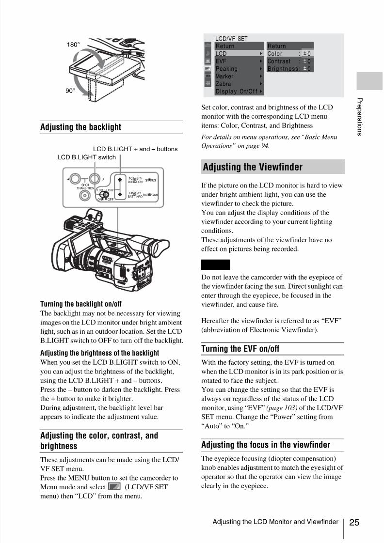
P r e p ar a t i on s Adjusting the backlight
Turning the backlight on/off
The backlight may not be necessary for viewing
images on the LCD monitor under bright ambient
light, such as in an outdoor location. Set the LCD
B.LIGHT switch to OFF to turn off the backlight.
Adjusting the brightness of the backlight
When you set the LCD B.LIGHT switch to ON,
you can adjust the brightness of the backlight,
using the LCD B.LIGHT + and – buttons.Press the – button to darken the backlight. Press
the + button to make it brighter.
During adjustment, the backlight level bar
appears to indicate the adjustment value.
Adjusting the color, contrast, andbrightness
These adjustments can be made using the LCD/
VF SET menu.
Press the MENU button to set the camcorder to
Menu mode and select (LCD/VF SET
menu) then “LCD” from the menu.
Set color, contrast and brightness of the LCD
monitor with the corresponding LCD menu
items: Color, Contrast, and Brightness
For details on menu operations, see “Basic Menu
Operations” on page 94.
If the picture on the LCD monitor is hard to view
under bright ambient light, you can use the
viewfinder to check the picture.
You can adjust the display conditions of the
viewfinder according to your current lighting
conditions.
These adjustments of the viewfinder have no
effect on pictures being recorded.
Do not leave the camcorder with the eyepiece of
the viewfinder facing the sun. Direct sunlight canenter through the eyepiece, be focused in the
viewfinder, and cause fire.
Hereafter the viewfinder is referred to as “EVF”
(abbreviation of Electronic Viewfinder).
Turning the EVF on/off
With the factory setting, the EVF is turned on
when the LCD monitor is in its park position or is
rotated to face the subject.You can change the setting so that the EVF is
always on regardless of the status of the LCD
monitor, using “EVF” (page 103) of the LCD/VF
SET menu. Change the “Power” setting from
“Auto” to “On.”
Adjusting the focus in the viewfinder
The eyepiece focusing (diopter compensation)
knob enables adjustment to match the eyesight of
operator so that the operator can view the imageclearly in the eyepiece.
P R E V R E
C
S T A R T / S T O
H O L D
l
H L O F F
90°
180°
O F F
2
1
N D F IL T E R
ZEBRA PEAKING
GAIN
BAPRST
LMH
WHITE BAL
FULL AUTO
SLOT SELECT
OPEN
ACCESS
AB
1
2
3
AS S I G N
L E N S I N F O B R T D I S P H I S T O G R A M
MENU
CH-1
AUDIOLEVEL
CH-2
AUTO
MANU
AL
INT
EXT
PICTUR
E
PROFI
LE
PMW-E
X1
DCIN
CH-2
AUTO
MANU
AL
INT
EXT
CH-1
AUDIO
SELECT
AUDIO
IN
OFF
CAMERA
CANCEL
SEL / SE
T
MEDIA 1
5
2 5
4 0
8 1
. 2
1 0
3
1 0
5
1 0
3 0
1 5
5 .
8
M AN U AU T O
MA N U A U T O
FOCUS
I R I S
M AC RO
OFF ON
T H U M B N A I L
F R E V
P R E V
S E L / S E T
P L A Y / P A U S E
S T O P
C A N C E L
F F W
D
N E X T
R E C
S T A
R T / S T O P
H O L D
R E C
R E V
I E W
l
s
L
j
G / S
J M O N I T O R V O L
H L O F F
A
S H O T
T R A N S IT I O N
B
L C D B .L I G H T T C / U - B I T /
D U R A T I O N S T A T U S
B A R S / C A M
D I S P L A Y B A T T I N F O
O N
O F F
A
SHOT
TRANSITION
B
LCD B.LIGHT
TC/U-BIT/
DURATION STATUS
BARS/CAMDISPLAY
BATT INFOON OFF
LCD B.LIGHT switch
LCD B.LIGHT + and – buttons
Adjusting the Viewfinder
Caution
00:00
Return
LCD
EVF
Peaking
Marker
Zebra
Display On/ O f f
LCD/VF SETReturn
Color
Contrast
Br ightness
: 0
: 0
: 0
: 0B
B
B
B
B
B

8/13/2019 Uputstvo Za Ex1
http://slidepdf.com/reader/full/uputstvo-za-ex1 26/132

8/13/2019 Uputstvo Za Ex1
http://slidepdf.com/reader/full/uputstvo-za-ex1 27/132
Adjusting the Grip / Using the IR Remote Commander 27
P r e p ar a t i on s
The grip rotates approx. 120 degrees to support a
variety of shooting styles.Holding the RELEASE button pressed, slowly
rotate the grip.
Click positions are provided at each 15 degrees.
Release the RELEASE button at the desired click
position to lock the grip.
Before useBefore you use the supplied IR Remote
Commander for the first time, pull out the
insulation sheet from the battery holder.
A CR2025 lithium battery is set in the holder at
the factory.
To use the IR Remote Commander
For controlling the camcorder from the IR
Remote Commander, activate the remote control
function of the camcorder after turning the power
on.
Activating/deactivating the remote control
function can be achieved using the Setup menu or
an assignable button.
To activate using the menu
Press the MENU button to set the camcorder to
Menu mode, select (the OTHERS menu)
and set “IR Remote” to “On.”
For details on menu operations, see “Basic Menu
Operations” on page 94.
To activate using an assignable button
Assigning “IR Remote” to one of the assignable
buttons permits you to activate/deactivate the
remote control function by pressing the button.
For the assignable buttons, see“Changing Functions
of the Assignable Buttons” on page 56 .
Adjusting the Grip
W-EX1
DC IN
FF
MEDIA
BATTERYRELEASE
A / V OU
TCOMPON
ENT
OUT
S H O T
T R A N S I T I O N
B
A
B . L I G H T
T C / U - B
I T /
D U
R A T I O N
S T A T U S
B A R S / C
A M
D I S P
L A Y
B A T T I N F O
O N
O F F
SDI OU
T
C H - 1
M I C
LI N E M I C + 4
8 V
M I C
LI N E M I C +
4 8 V
E X P A N D E D F O C U S
R E C R E V I E W
R E L E A S E
S T AR T / S T O P
R E L E A S E
RELEASE
RELEASE button
Grip
Using the IR RemoteCommander
Insulation sheet
00:00
OTHERSC lock Set
Language : Eng l i sh
Assign But ton
Tal l y
Hours
Meter IR Remote : O n
Ba t te r y Alarm
O n
O f f
B
B
B
B
B B

8/13/2019 Uputstvo Za Ex1
http://slidepdf.com/reader/full/uputstvo-za-ex1 28/132
Using the IR Remote Commander28
P r e p ar a t i on s
Note
To avoid malfunctions, the remote control
function is automatically deactivated when the
camcorder is turned off. Activate the function
each time when required after you turn the
camcorder on.
Battery lifetimeWhen the lithium battery’s power falls, the IR
Remote Commander may not work even if you
press the buttons. The average lithium battery’s
service life is about one year, but this depends on
the pattern of use.
If pressing the remote control buttons produces
absolutely no effect on the camcorder, replace the
battery then check the operation again.
Replacing the battery in the IR RemoteCommander
Use a commercially available CR2025 lithium
battery. Do not use any battery other than a
CR2025.
1 Hold down the lock lever 1, pull out
the battery holder 2, and remove the
battery.
2 Place a new battery in the battery
holder with the + symbol facing upward
1, then push the battery holder into the
IR Remote Commander until it clicks
2.
Battery may explode if mistreated.
Do not recharge, disassemble, or dispose of in
fire.
• Danger of explosion if battery is incorrectly
replaced. Replace only with the same or
equivalent type recommended by the
manufacturer.
• Dispose of used batteries according to the
manufacturer’s instructions.
1 2
1
2
With the + symbol upward
WARNING
CAUTION

8/13/2019 Uputstvo Za Ex1
http://slidepdf.com/reader/full/uputstvo-za-ex1 29/132

8/13/2019 Uputstvo Za Ex1
http://slidepdf.com/reader/full/uputstvo-za-ex1 30/132
Handling SxS Memory Cards30
P r e p ar a t i on s
Note
Do not operate the write-protect switch of an SxS
memory card while it is set in the camcorder.
Temporarily remove the card from the camcorder
before changing the switch setting.
Inserting an SxS memory card
1 Slide the cover to the left to open.
2 Insert the SxS memory card into the
slot.
The ACCESS lamp lights in red then changes
to green once the memory card is ready for
use.
3 Close the cover.
Status indications by the ACCESS lamps
Card slots A and B are accompanied by the
respective ACCESS lamps to indicate their
statuses.
Removing an SxS memory card
1 Open the cover, once press the EJECT
button to release the lock, then pull the
button out.
2 Press the EJECT button again toremove the card.
Inserting/Removing an SxS
Memory Card
Write-protect switch
O F F
2
1
N D F IL T E R
ZEBRAPEAKING
GAIN
BA
PRST
LMH
WHITE BAL
FULLAUTO
SLOT SELECT
OPEN
ACCESS
AB
1
2
3
AS S I G N
L E N S I N F O B R T D I S P H I S T O G R A M
MENU
CH-1
AUDIOLEVEL
CH-2
AUTO
MANUA
L
INT
EXT
PICTUR
E
PROFI
LE
PMW-E
X1
DCIN
CH-2
AUTO
MANU
AL
INT
EXT
CH-1
AUDIO
SELECT
AUDIO
IN
OFF
CAMERA
CANCEL
SEL / SE
T
MEDIA 1
5
2 5
4 0
8 1
. 2
1 0
3
1 0
5
1 0
3 0
1 5
5 .
8
M AN U AU T O
MA N U A U T O
FOCUS
I R I S
M AC RO
OFF ON
T H U M B N A I L
F R E V
P R E V
S E L / S E T
P L A Y / P A
U S E
S T O P
C A N C
E L
F F W
D
N E X T
R E C
S T A
R T / S T O
P
H O L D
R E C
R E V I E W
l
s
L
j
G / S J M
O N I T O R V O
L
H L O F F
A
S H O T
T R A N S IT I O N
B
L C D B .L I G H T T C / U - B I T /
D U R A T I O N
S T A T U S
B A R S / C A M
D I S P L A Y B A T T I N F O
O N
O F F
SLOT SELECTA B
OPEN
ACCESS
SLOT SELECT button
Card slots
ACCESS lamps
EJECT buttons
Cover
Lamp Slot statuses
Lights in
red
Accessing the loaded SxS memory card
(writing/reading data)
Lights in
green
Standby (ready for recording or
playback using the loaded SxS memory
card)
Off • No SxS memory card is loaded.
• The loaded card is invalid.• An SxS memory card is loaded, but
another slot is active.
BAL
FULL AUTO
SLOT SELECT
AB MENU
CH-1
CH-2 CH-2
CH-1
AU
SEL
SEL
OPEN
ACCESS
Sx SPR O 8 GB
With the labelfacing right
BAL
FULL AUTO
SLOT SELECT
AB MENU
CH-1
CH-2 CH-2
CH-1
AU
SEL
SEL
OPEN
ACCESS
Press and unlockthe button.

8/13/2019 Uputstvo Za Ex1
http://slidepdf.com/reader/full/uputstvo-za-ex1 31/132
Handling SxS Memory Cards 31
P r e p ar a t i on s
Notes
• Data are not guaranteed if the power is turned
off or a memory card is removed while the card
is being accessed. All data on the card may be
destroyed. Be sure that the ACCESS lamps are
lit in green or off when you turn off the power
or remove memory cards.
• When you turn the camcorder on by setting thepower switch to MEDIA (Media mode), a
display to show that an SxS memory card is
being confirmed appears on the LCD monitor/
EVF screen.
The display automatically changes to the
thumbnail screen (page 77) when a valid
memory card is inside, but it remains on the
screen if no valid memory card is loaded.
When SxS memory cards are loaded in both card
slots A and B, press the SLOT SELECT button to
select the card you wish to use.If a card becomes full during recording, switching
to the other card is automatically executed.
Note
The SLOT SELECT button is disabled while
playback is in progress. Switching is not executed
even if you press the button. The button is enabled
on the thumbnail screen (page 77).
Formatting may be required before using an SxS
memory card with this camcorder. For an SxS
memory card that is not formatted or that was
formatted with another system, a message to
confirm if formatting is to be executed is
displayed on the LCD monitor/EVF screen.
Any SxS memory card formatted with a device
other than this camcorder cannot be used with thecamcorder.
To execute formatting
If the message for formatting is displayed,
turn the jog dial or tilt the joystick to select
“Execute” then press the dial or joystick.
Formatting begins.
The in-progress message and status bar (%) are
displayed, and the ACCESS lamp lights in red.
When formatting is completed, the completion
message is displayed for three seconds.
Recording/playback during formatting
You can perform recording or playback using the
SxS memory card in the other card slot while
formatting is in progress.
If formatting fails
A write-protected SxS memory card or memory
card that cannot be used with this camcorder will
not be formatted.As a warning message is displayed, replace the
card with an appropriate SxS memory card, as per
the instructions in the message.
To format by menu operation
When no formatting message is displayed on the
LCD monitor/EVF screen, you can execute
formatting using “Format Media” (page 108) of
the OTHERS menu in the same manner.
Notes
• All the data, including recorded pictures and
setup files, are erased when a memory card is
formatted.
• SxS memory cards to be used with this
camcorder must be formatted using the format
function of this camcorder. Any card formatted
with other device must be formatted again with
this camcorder.
Switching Between SxS MemoryCards
Formatting an SxS Memory Card
BAL
FULL AUTO
SLOT SELECT
AB MENU
CH-1
CH-2 CH-2
CH-1
AU
SEL
SEL
OPEN
ACCESS
Note on formatting

8/13/2019 Uputstvo Za Ex1
http://slidepdf.com/reader/full/uputstvo-za-ex1 32/132
Handling SxS Memory Cards32
P r e p ar a t i on s
In Camera mode, you can check the time
remaining for the SxS memory cards loaded in the
card slots on the LCD monitor/EVF screen.
The available time for recording with the current
video format (recording bit rate) is calculated
according to the remaining space of each card and
displayed in time units of minutes.
The remaining can also be checked in a meter
format on the BATTERY/MEDIA status screen(page 91).
Note
A icon appears if the memory card is write-
protected.
Replacing an SxS memory card
• If the available time on two cards in total
becomes less than 5 minutes, a message “Media
Near Full,” flashing of the tally lamps, and abeep sound will warn you. Replace the cards
with those with sufficient space.
• If you continue recording until the total
remaining time reaches zero, the message
changes to “Media Full,” and recording stops.
Note
Approximately 600 clips can be recorded on one
SxS memory card at maximum.
If the number of recorded clips reaches the limit,
the remaining time indication becomes “0,” and
the message “Media Full” is displayed.
If an error occurs with data in a memory card for
some reason, the card must be restored.
If an SxS memory card that needs to be restored
is loaded, a message that prompts you to execute
a restore operation is displayed on the LCD
monitor/EVF screen.
To restore a card
Select “Execute” by turning the jog dial or
tilting the joystick then push the dial or
joystick.
The restore operation begins.
During restoration, the in-progress message andstatus bar (%) are displayed, and the ACCESS
lamp is lit in red.
When restoration is completed, the completion
message is displayed for three seconds.
If restoration fails
• A write-protected SxS memory card or one on
which an error occurred cannot be restored. For
such a card, a warning message is displayed.
Release the write protection or replace the card,
as per the instructions in the message.• An SxS memory card on which an error
occurred may become usable again through
repeated formatting.
• In some cases, only parts of clips cannot be
restored. Playback of the restored clips becomes
possible again.
Recording/playback during restoration
You can perform recording or playback using the
SxS memory card in the other card slot while
restoration is in progress.
Checking the Remaining TimeAvailable for Recording
Restoring an SxS Memory Card
120min STBY STBYA: 25minB: 50minZ99

8/13/2019 Uputstvo Za Ex1
http://slidepdf.com/reader/full/uputstvo-za-ex1 33/132
Basic Operation Procedure 33
R e c or d i n g
Basic recording can be performed with the following procedures:
Preparations
1 Mount a fully charged battery pack.
2 Load SxS memory card(s).
If you load two cards, recording is continued
by automatically switching to the second
card when the first card becomes full.
3 Pull up on the lens cap open/close lever
to open the lens cap built in the lens
hood.
4 Adjust the angle of the LCD monitor for
the best view.
When you wish to use the EVF, fold the LCD
monitor to its park position and adjust the
angle of the EVF.
5 Set the power switch to the CAMERAposition.
The camcorder is turned on and enters
Camera mode.
When using the remote commander, activate the remote
control mode (page 27).
Note
When you hold the camcorder by the grip,
support it from underneath with your left hand.
Recording (Full Auto mode)
6 Press the FULL AUTO button so thatthe button indicator lights.
Recording
Basic Operation Procedure
1
2
3
47,8
9
5
6
O F F
2
1
N D F I L T E R
ZEBRAPEAKING
GAIN
BAPRST
LMH
WHITE BAL
FULL AUTO
SLOT SELECT
OPEN
ACCESS
AB
1
2
3
AS S I G N
L E N S I N F O B R T D I S P H I S T O G R A M
MENU
CH-1
AUDIOLEVEL
CH-2
AUTO
MANUAL
INT
EXT
PICTUR
E
PROFILE
PMW-E
X1
DCIN
CH-2
AUTO
MANUA
L
INT
EXT
CH-1
AUDIO
SELECT
AUDIO
IN
OFF
CAMERA
CANCEL
SEL / SE
T
MEDIA 1
5
2 5
4 0
8 1
. 2
1 0
3
1 0
5
1 0
3 0
1 5
5 .
8
M AN U AU T O
MA N U A U T O
FOCUS
I R I S
M AC RO
OFF ON
T H U M B N A I L
F R E V
P R E V
S E L / S E T
P L A Y / P A U
S E
S T O P
C A N C E L
F F W
D
N E X T
R E C
S T A R T / S T O P
H O L D
R E C
R E V I E W
l
s
L
j
G / S
J M O N I T O R V O
L
H L O F F
A
S H O T
T R A N S I T I O N
B
L C D B .L I G H T T C /U - B I T /
D U R A T I O N S T A T U S
B A R S / C A M
D I S P L A Y B A T T I N F O
O N
O F F
OFFCAMERA MEDIA
REC START/STOP
REC REVIEW
FULL AUTOMemory card(s)
Battery packLens cap OPEN
LCD monitor
Power switch: CAMERA

8/13/2019 Uputstvo Za Ex1
http://slidepdf.com/reader/full/uputstvo-za-ex1 34/132
Basic Operation Procedure34
R e c or d i n g
Full Auto mode is turned on, activating the
TLCS (Total Level Control System) (page
100).
Thus Auto Iris, AGC (Auto Gain Control),
Auto Shutter, ATW (Auto Tracing White)
are set to ON, whereby the brightness and
white balance will be automatically adjusted.
When you wish to adjust them manually, turn Full
Auto mode off, and see;
“Adjusting the Iris” on page 44
“Setting the Gain” on page 41
“Setting the Electronic Shutter” on page 42
“Adjusting the White Balance” on page 37
AF (Auto Focus) is not activated by setting
the camcorder to Full Auto mode.
For information of automatic focus adjustment,
see page 49.
7 Press the REC START/STOP button.
You can start with either of the REC START/
STOP button on the handle or that on the
grip.
(If you are using the IR Remote Commander, press
the REC button simultaneously with the unmarked
button.)
The front and rear tally lamps light and
recording begins.
8 To stop recording, press the REC
START/STOP button again.
(If you are using the IR Remote Commander, press
the REC PAUSE button simultaneously with the
unmarked button.)
Recording stops and the camcorder enters
STBY (recording standby) mode.
Note
Recording cannot be restarted after you stop
recording until the ACCESS lamp lights in green.
To prevent a switching error
The REC START/STOP button on the handle is
incorporated with the REC HOLD lever. If the
REC START/STOP button on the handle will not
be used, it is recommended to set the lever to the
HOLD position to lock the button.
To unlock the button, return the lever to its
original position.
Checking the last recorded clip (RecReview)
9 Press the REC REVIEW button.
The Rec Review function (page 56) is
activated, and the last recorded clip is played
back for the specified time on the LCD
monitor/EVF screen.
When playback reaches the end of the clip,
the camcorder returns to STBY (recording
standby) mode.
To delete clips
You can delete the last recorded clip by using the
Last Clip DEL function.
See“Deleting the Last Recorded Clip” on page 75.
Use the All Clips DEL function when you wish to
delete all recorded clips from a memory card.
See“Deleting All Clips” on page 75.
To specify a clip to be deleted, operate the
camcorder in Media mode.
See“Deleting a Clip” on page 84.
Note
REC
START/STOP
HOLD
REC HOLD lever

8/13/2019 Uputstvo Za Ex1
http://slidepdf.com/reader/full/uputstvo-za-ex1 35/132
Selecting the Video Format 35
R e c or d i n g
L
You can select various video formats for
recording/playback using “Video Format” (page108) of the OTHERS menu.
The current format is displayed on the screen
when you press the DISPLAY/BATT INFO
button.
The selectable formats depend on whether
“Country” (page 108) of the OTHERS menu is
set to “NTSC Area” or “PAL Area.”
The video formats set on this camcorder cover the
recording bit rate (HQ/SP), recording picture size
(effective resolution), recording frame rate, and
recording scan system (i/P).
The frame rates are indicated with two-digit
integers, rounding off the fractional part.
When you select an HQ format, recording is made
with the bit rate of 35 Mbps VBR.
When you select an SP format, recording is made
with the HDV-compatible bit rate of 25 Mbps
CBR.
With “NTSC Area” selected
Clip (recording data) and clip name
When you stop recording, video, audio and
subsidiary data from the start to end of the
recording are recorded as a single clip on an
SxS memory card.
For each clip recorded with this camcorder, a
clip name of 8 characters (the first fouralphanumerics and the second four numerics) is
automatically generated.
Example: ABCD0001
The first four alphanumerics can be specified as
desired using “Clip” (page 108) of the
OTHERS menu before you start recording. (It
cannot be changed after recording.)
The second four-digit number is automatically
counted up in sequence.
Notes on Clips
The XDCAM EX-series products employ the
FAT32 File System.
Thus, recorded materials may be segmented in
multiple files depending on the file size. But the
camcorder can play such materials seemlessly.
A long clip can be recorded crossing over two
memory cards in slot A and B.
When you copy clips to a hard disk drive, etc.
using a computer, it is recommended to use the
XDCAM EX Clip Browsing Software on thesupplied CD-ROM.
Note
If copying is done using Explorer (Windows)
or Finder (MAC), the continuity and
relationships of recorded materials may not be
maintained.
Selecting the VideoFormat
Selectable Formats
Format Indication on thiscamcorder
HQ 1920 × 1080
59.94 interlace
HQ 1080/60i
SP 1440 × 1080
59.94 interlace
SP 1080/60i
HQ 1920 × 1080
29.97 Progressive
HQ 1080/30P
HQ 1920 × 1080
23.98 Progressive
HQ 1080/24P
SP 1440 × 1080
23.98 Progressive
SP 1080/24P
HQ 1280 × 720
59.94 Progressive
HQ 720/60P
TCG 00:00:00:00HQ 1080/60iS&Q Motion
29/24 f s
BY STBY
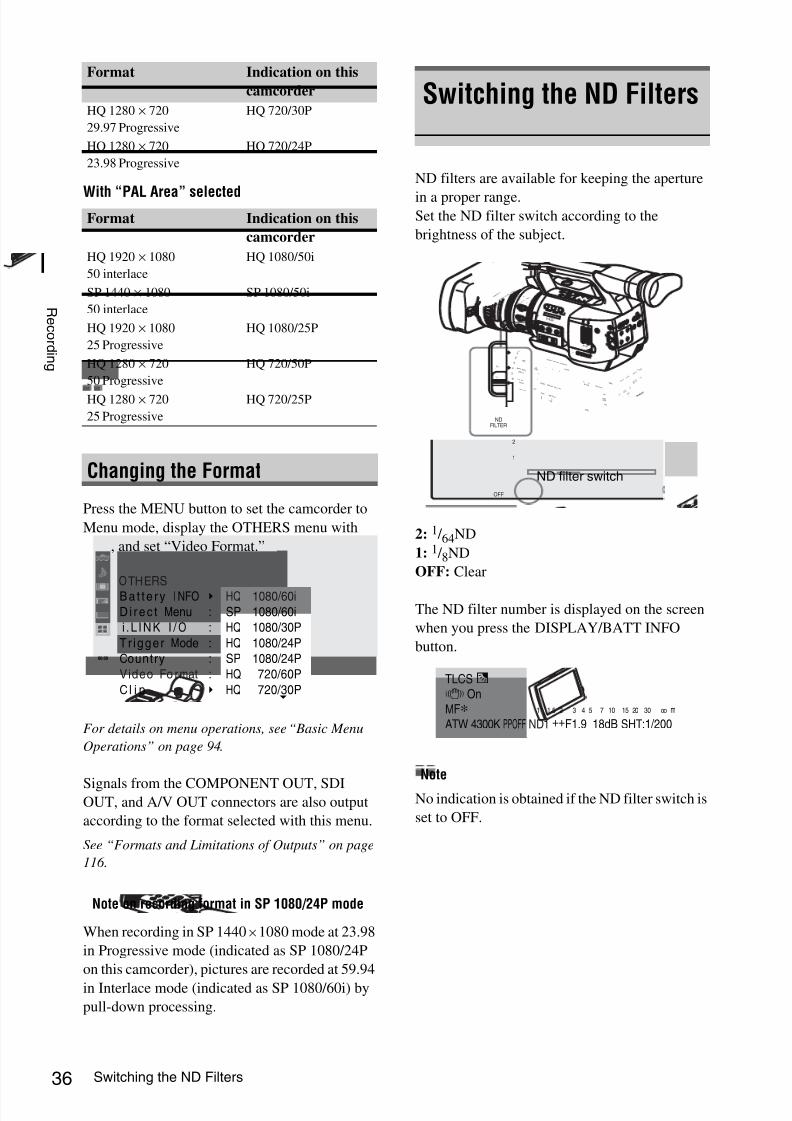
8/13/2019 Uputstvo Za Ex1
http://slidepdf.com/reader/full/uputstvo-za-ex1 36/132
Switching the ND Filters36
R e c or d i n g
With “PAL Area” selected
Press the MENU button to set the camcorder to
Menu mode, display the OTHERS menu with
, and set “Video Format.”
For details on menu operations, see “Basic Menu
Operations” on page 94.
Signals from the COMPONENT OUT, SDIOUT, and A/V OUT connectors are also output
according to the format selected with this menu.
See “Formats and Limitations of Outputs” on page
116 .
When recording in SP 1440 × 1080 mode at 23.98
in Progressive mode (indicated as SP 1080/24P
on this camcorder), pictures are recorded at 59.94
in Interlace mode (indicated as SP 1080/60i) by
pull-down processing.
ND filters are available for keeping the aperture
in a proper range.Set the ND filter switch according to the
brightness of the subject.
2: 1 / 64ND
1: 1 / 8ND
OFF: Clear
The ND filter number is displayed on the screen
when you press the DISPLAY/BATT INFO
button.
Note
No indication is obtained if the ND filter switch is
set to OFF.
HQ 1280 × 720
29.97 Progressive
HQ 720/30P
HQ 1280 × 720
23.98 Progressive
HQ 720/24P
Format Indication on this
camcorder
HQ 1920 × 1080
50 interlace
HQ 1080/50i
SP 1440 × 1080
50 interlace
SP 1080/50i
HQ 1920 × 1080
25 Progressive
HQ 1080/25P
HQ 1280 × 720
50 Progressive
HQ 720/50P
HQ 1280 × 720
25 Progressive
HQ 720/25P
Changing the Format
Note on recording format in SP 1080/24P mode
Format Indication on this
camcorder
00:00
OTHERS
Ba t te r y
INFO
D i re c t Menu
i .L INK I / O
Tr igger Mode
Country
Video Fo rmat
C l i p
:
:
:
:
:
B
B B
HQ
1080/60i
SP 1080/60i
HQ 1080/30P
HQ 1080/24P
SP 1080/24P
HQ 720/60P
HQ 720/30P
Switching the ND Filters
O F F
2
1
N D F I L T E R
ZEBRAPEAKING
GAIN
BAPRST
LMH
WHITE BAL
FULL AUTO
SLOT SELECT
OPEN
ACCESS
AB
1
2
3
AS S IG N
L E N S I N F O B R T D I S P H I S T O G R A M
MENU
CH-1
AUDIOLEVEL
CH-2
AUTO
MANUA
L
INT
EXT
PICTUR
E
PROFIL
E
PMW-EX1
DCIN
CH-2
AUTO
MANUA
L
INT
EXT
CH-1
AUDIO
SELECT
AUDIOIN
OFF
CAMER
A
CANCEL
SEL / SE
T
MEDIA 1
5
2 5
4 0
8 1
. 2
1 0
3
1 0
5
1 0
3 0
1 5
5 .
8
M AN U AU T O
MA N UA U T O
FOCUS
I R I S
M AC RO
OFF ON
T H U M
B N A I L
F R E V
P R E V
S E L / S E T
P L A Y / P A U S
E
S T O
P
C A N
C E L
F F W D
N E X T
R E C
S T A R T / S T O
P
H O L D
R E C
R E V I E W
l
s
L
j
G / S
J M O N I T O
R V O L
H L O F F
A
S H O T T R A N S I T IO
N B
L C D B .L I G H T T C /U - B IT /
D U R A T IO N S T A T U S
B A R S / C A M
D IS P L A Y B A T T I N F O
O N
O F F
OFF
2
1
ND
FILTER
ND filter switch
TLCS.7 OnMF∗ATW 4300K PPOFF ND1 ++F1.9 18dB SHT:1/200
1 1.5 2 3 4 5 7 10 15 20 30 oo m

8/13/2019 Uputstvo Za Ex1
http://slidepdf.com/reader/full/uputstvo-za-ex1 37/132
Adjusting the White Balance 37
R e c or d i n g
The white balance must be adjusted to suit to the
color temperature of the light source.You can select the adjustment mode according to
the shooting conditions.
Preset mode
The color temperature is adjusted to the preset
value (factory setting: 3200K) in this mode.
Select this mode when there is no time to adjust
the white balance or when you wish to fix the
white balance to a standard condition.
Memory A mode, Memory B mode
• The white balance is adjusted to the value stored
in memory A or memory B.
• Pressing the WHT BAL button executes auto
white balance and stores the adjusted value in
memory A or memory B.
ATW (Auto-Tracing White balance) mode
In this mode, the camcorder automatically adjuststhe white balance to the appropriate condition.
When the color temperature of the light source
changes, the white balance adjustment is
automatically executed.
Five steps of adjustment speed can be selected
with “ATW Speed” (page 100) of the CAMERA
SET menu.
Using the switch
You can select Preset mode, Memory A mode, or
ATW (Memory B) mode with the WHITE BAL
switch.
To the B position of the WHITE BAL switch,
ATW mode is assigned at the factory. The setting
can be changed with “White Switch <B>” (page
100) of the CAMERA SET menu to select
Memory B mode.
B: ATW or Memory B mode
A: Memory A mode
PRST: Preset mode
• Setting the camcorder to Full Auto mode (page
33) forcibly activates ATW mode.
• Assigning the ATW on/off function to an
assignable button permits you to independently
activate/deactivate ATW when Full Auto mode
is off.
For details on the assignable buttons, see “Changing
Functions of the Assignable Buttons” on page 56 .
Using the Direct menu
When you press the DISPLAY/BATT INFO
button, the current adjustment mode and color
temperature are displayed on the screen.
ATW: ATW mode
W:A: Memory A mode
W:B: Memory B mode
W:P: Preset mode
When the Direct menu is in All mode, you can
select from among ATW, W:A, W:B, and W:P.
When the Direct menu is in Part mode, you can
switch between ATW and the mode set with the
WHITE BAL switch.
For details on the Direct menu, see “Direct Menu
Operation” on page 19.
Adjusting the WhiteBalance
Selecting the Adjustment Mode
O F F
2
1
N D F IL T E R
ZEBRA PEAKING
GAIN
BAPRST
LMH
WHITE BAL
FULL AUTO
SLOT SELECT
OPEN
ACCESS
AB
1
2
3
AS S I G N
L E N S I N F O B R T D I S P H I S T O G R A M
MENU
CH-1
AUDIOLEVEL
CH-2
AUTO
MANU
AL
INT
EXT
PICTUR
E
PROFI
LE
PMW-E
X1
DCIN
CH-2
AUTO
MANU
AL
INT
EXT
CH-1
AUDIO
SELECT
AUDIO
IN
OFF
CAMERA
CANCEL
SEL / SE
T
MEDIA 1
5
2 5
4 0
8 1
. 2
1 0
3
1 0
5
1 0
3 0
1 5
5 .
8
M AN U AU T O
MA N U A U T O
FOCUS
I R I S
M AC RO
OFF ON
T H U M B N A I L
F R E V
P R E V
S E L / S E T
P L A Y / P A U S E
S T O P
C A N C
E L
F F W
D
N E X T
R E C
S T A
R T / S T O P
H O L D
R E C
R E V I E W
l
s
L
j
G / S
J M O N I T O
R V O
L
H L O F F
A
S H O T
T R A N S IT I O N
B
L C D B .L I G H T T C / U - B I T /
D U R A T I O N S T A T U S
B A R S / C A M
D I S P L A Y B A T T I N F O
O N
O F F
ZEBRA PEAKING
GAIN
BA
PRST
LMH
WHITE BAL
FULL AUTO
WHITE BAL switch
TLCS.
7 On
MF∗ATW 4300K PPOFF ND1 ++F1.9 18dB SHT:1/200
1 1.5 2 3 4 5 7 10 15 20 30 oo m

8/13/2019 Uputstvo Za Ex1
http://slidepdf.com/reader/full/uputstvo-za-ex1 38/132
Adjusting the White Balance38
R e c or d i n g
Execute auto white-balance adjustment according
to the color temperature of the light source.
The adjustment value can be stored in memory A
or B.
Note
Auto white-balance adjustment cannot be
executed in Preset mode.
1 To store the adjustment value in
memory, select Memory A or Memory
B mode.
2 Select the appropriate ND filter
according to the lighting condition.
3 Place a white subject under the same
lighting condition and zoom in on it so
that a white area is obtained on the
screen.
A white object (white cloth, a white wall,
etc.) near the subject may be used in place.
Be careful not to have any spots of high
illumination on the screen.
4Adjust the lens iris opening.
Set it to the proper condition if the manual
iris adjustment mode is selected.
5 Press the WHT BAL button.
Auto white-balance adjustment begins.
During adjustment, an in-progress message is
displayed on the screen. When the adjustment is
completed successfully, the message changes to a
completion message, and the obtained color
temperature is displayed.
• When you execute the adjustment in a memory
mode, the adjusted value is stored in memory
(A or B) selected in step 1.
• When you execute the adjustment in ATW
mode, adjustment in ATW is resumed.
If auto white-balance adjustment fails
An error message is displayed on the screen for
approximately three seconds.
If the error message is displayed, try auto white-
balance adjustment again.
If the error message continues to be displayed
after several attempts, consult your Sony service
representative.
Executing Auto White Balance
BATTERYRELEASE
SDI OUTA /V OUT
E X P A N D E D
F O C U S
R E C
R E V I E W
R E L E A S E
S T A R T /
S T O P
A
S H O T
T R A N S I T I O
N B
L C D B . L I G H T T C / U - B I T /
D U R A T I O N S T A T U S
B A R S / C A M
D I S P L A Y
B A T T I N F O
O N
O F F
P R E V
P L A
Y / P A
U S
E
S T O P
C A N C E L
F F W
D
N E X T
R E C
S T A R T / S T O P
H O L D
l
s
L
j
G / S
J
H L O F F
T H U M B N A I L
F R E V
S E L / S E T
M O N I T O R
V O L
A U D I O I N
C H - 1
M I C L I N E M I C + 4 8 V M I C L I N E
M I C + 4 8 V
C H - 2
ASSIGN 4 OFF ON
SHUTTER
WHT BAL
WHT BAL button

8/13/2019 Uputstvo Za Ex1
http://slidepdf.com/reader/full/uputstvo-za-ex1 39/132
Displaying the Markers and Zebra Patterns 39
R e c or d i n g
During recording, various markers and zebra
patterns can be inserted into the image on theLCD monitor/EVF screen.
This does not affect recording signals.
Use “Marker” of the LCD/VF SET menu.
Press the MENU button to set the camcorder to
Menu mode, display the LCD/VF SET menu with
, and select “Marker” from the menu.
Activating the marker indications
• Set “Setting” to “On” then turn the markers on/
off independently.
No marker is displayed when “Setting” is “Off.”
• Assigning the Marker on/off function to one of
the assignable buttons permits you to operate
“Setting: On/Off” by pressing the button.
For the assignable buttons, see “Changing
Functions of the Assignable Buttons” on page 56 .
Displaying the safety-zone marker
Set “Safety Zone” to “On” to insert the safety-
zone marker to the screen.
With “Safety Area” you can select the size of the
safety-zone marker from among 80%, 90%,
92.5%, and 95% of the picture area.
When the aspect marker is on, the safety zone
marker shows the effective area within the aspect
marker.
Displaying the center marker
Set “Center Marker” to “On” to insert the center
marker into the screen area.
Displaying the aspect marker
Set “Aspect Marker” to “On” to insert the aspect
marker into the screen area.Select the width of the marker from among 4:3,
13:9, 14:9, and 15:9 with “Aspect Select.”
Displaying the guide frame lines
Set “Guide Frame” to “On” to insert the guide
frame lines into the screen area.
Displaying the Markersand Zebra Patterns
Displaying the Markers
00:00
Return
LCD
EVF
Peaking
Marker
Zebra
D isp lay On/ O f f
LCD/VF SET
Return
S e t t i n g
Safety Zone
Safety Area
Center Marker
Aspect Marker
Aspect Select
: On
: On
: 90%
: On
: On
: 4 : 3
B
B
B
B
B
B
TCG 00:00:00:00 120min STBY
Example: 95%
TCG 00:00:00:00 120min STBY
TCG 00:00:00:00 120min STBY
Example: 4:3
TCG 00:00:00:00 120min STBY

8/13/2019 Uputstvo Za Ex1
http://slidepdf.com/reader/full/uputstvo-za-ex1 40/132
Displaying the Markers and Zebra Patterns40
R e c or d i n g
A zebra pattern(s) can be inserted to the picture
on LCD monitor/EVF screen to check the
appropriate luminance level.
Turning the zebra-pattern indication on/
offPressing the ZEBRA button turns the zebra
pattern-indication on/off.
Changing the zebra pattern
Using “Zebra” of the LCD/VF SET menu, you
can change the zebra pattern to be displayed.
Press the MENU button to set the camcorder to
Menu mode, display the LCD/VF SET menu with
, and select “Zebra” from the menu.
Zebra Select
Select the zebra pattern(s) to be displayed.
1 (Zebra1): To display a zebra pattern in the area
of ±10% centering the video level set with
“Zebra1 Level.”
2 (Zebra2): To display a zebra pattern for the
video level over 100%.
Both: To display both Zebra1 and Zebra2
Zebra1 Level
Set the center level of Zebra1 in the range of 50 to
107%. The default setting is 70%.
Displaying the Zebra Patterns
Factory-set zebras
1 (70%) 2 (100%)
O F F
2
1
N D F IL T E R
ZEBRA PEAKING
GAIN
BAPRST
LMH
WHITE BAL
FULLAUTO
SLOT SELECT
OPEN
ACCESS
AB
1
2
3
AS S I G N
L E N S I N F O B R T D I S P H I S T O G R A M
MENU
CH-1
AUDIOLEVEL
CH-2
AUTO
MANUAL
INT
EXT
PICTUR
E
PROFILE
PMW-E
X1
DCIN
CH-2
AUTO
MANUA
L
INT
EXT
CH-1
AUDIO
SELECT
AUDIO
IN
OFF
CAMERA
CANCE
L
SEL / SE
T
MEDIA 1
5
2 5
4 0
8 1
. 2
1 0
3
1 0
5
1 0
3 0
1 5
5 .
8
M AN U AU T O
MA N U A U T O
FOCUS
I R I S
M AC RO
OFF ON
T H U M
B N A
I L
F R E V
P R E V
S E L / S E T
P L A Y / P A U S
E
S T O P
C A N
C E L
F F W D
N E X T
R E C
S T A R T / S T O P
H O L D
R E C
R E V I E W
l
s
L
j
G / S
J M O N I T O R V O L
H L O F F
A
S H O T T R A N
S IT I O N B
L C D B .L IG H T T C /U - B IT /
D U R A T IO N S T A T U S
B A R S / C A M
D I S P L A Y B A T T IN F O
O N
O F F
ZEBRA PEAKING
GAIN
BA
PRST
LMH
WHITE BAL
FULL AUTO
ZEBRA button
00:00
Return
LCD
EVF
Peaking
Marker
Zebra
Display On/ O f f
LCD/VF SET
Return
Zebra Select
Zebra1 Level
: 1
: 70
B
B
B
B
B
B
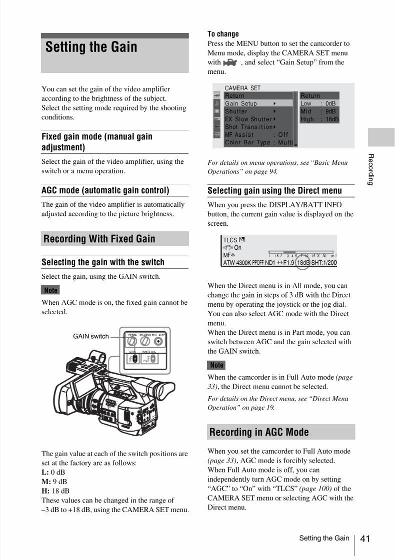
8/13/2019 Uputstvo Za Ex1
http://slidepdf.com/reader/full/uputstvo-za-ex1 41/132
Setting the Gain 41
R e c or d i n g
You can set the gain of the video amplifier
according to the brightness of the subject.Select the setting mode required by the shooting
conditions.
Fixed gain mode (manual gainadjustment)
Select the gain of the video amplifier, using the
switch or a menu operation.
AGC mode (automatic gain control)
The gain of the video amplifier is automatically
adjusted according to the picture brightness.
Selecting the gain with the switch
Select the gain, using the GAIN switch.
Note
When AGC mode is on, the fixed gain cannot be
selected.
The gain value at each of the switch positions are
set at the factory are as follows:
L: 0 dB
M: 9 dB
H: 18 dBThese values can be changed in the range of
–3 dB to +18 dB, using the CAMERA SET menu.
To change
Press the MENU button to set the camcorder to
Menu mode, display the CAMERA SET menu
with , and select “Gain Setup” from the
menu.
For details on menu operations, see “Basic Menu
Operations” on page 94.
Selecting gain using the Direct menu
When you press the DISPLAY/BATT INFO
button, the current gain value is displayed on the
screen.
When the Direct menu is in All mode, you can
change the gain in steps of 3 dB with the Directmenu by operating the joystick or the jog dial.
You can also select AGC mode with the Direct
menu.
When the Direct menu is in Part mode, you can
switch between AGC and the gain selected with
the GAIN switch.
Note
When the camcorder is in Full Auto mode (page
33), the Direct menu cannot be selected.
For details on the Direct menu, see “Direct Menu
Operation” on page 19.
When you set the camcorder to Full Auto mode
(page 33), AGC mode is forcibly selected.
When Full Auto mode is off, you can
independently turn AGC mode on by setting
“AGC” to “On” with “TLCS” (page 100) of theCAMERA SET menu or selecting AGC with the
Direct menu.
Setting the Gain
Recording With Fixed Gain
O F F
2
1
N D F I L T E R
ZEBRAPEAKING
GAIN
BAPRST
LMH
WHITE BAL
FULLAUTO
SLOT SELECT
OPEN
ACCESS
AB
1
2
3
AS S IG N
L E N S I N F O B R T D I S P H I S T O G R A M
MENU
CH-1
AUDIOLEVEL
CH-2
AUTO
MANUA
L
INT
EXT
PICTUR
E
PROFIL
E
PMW-E
X1
DCIN
CH-2
AUTO
MANUA
L
INT
EXT
CH-1
AUDIO
SELECT
AUDIO
IN
OFF
CAMER
A
CANCEL
SEL / SE
T
MEDIA 1
5
2 5
4 0
8 1
. 2
1 0
3
1 0
5
1 0
3 0
1 5
5 .
8
M AN U AU T O
MA N UA U T O
FOCUS
IR I S
M AC RO
OFF ON
T H U M
B N A I L
F R E V
P R E V
S E L / S E T
P L A Y / P A U S
E
S T O
P
C A N
C E L
F F W D
N E X T
R E C
S T A R T / S T O
P
H O L D
R E C
R E V I E W
l
s
L
j
G / S
J M O N I T O R
V O L
H L O F F
A
S H O T T R A N S I T IO
N B
L C D B .L I G H T T C /U - B I T /
D U R A T IO N S T A T U S
B A R S / C A M
D IS P L A Y B A T T I N F O
O N
O F F
ZEBRA PEAKING
GAIN
BA
PRST
LMH
WHITE BAL
FULL AUTOGAIN switch
Recording in AGC Mode
00:00
ReturnLow
Mid
High
: 0dB
: 9dB
: 18dB
ReturnGain Setup
Shut ter
EX S low Shut ter
Shot Trans i t ion
MF As s i s t : Of f
Color Bar Type : Mu l t i
CAMERA SET
B
B
B
B
B
TLCS.7 On
MF∗ATW 4300K PPOFF ND1 ++F1.9 18dB SHT:1/200
1 1.5 2 3 4 5 7 10 15 20 30 oo

8/13/2019 Uputstvo Za Ex1
http://slidepdf.com/reader/full/uputstvo-za-ex1 42/132
Setting the Electronic Shutter42
R e c or d i n g
The electronic shutter of the camcorder permits
you to change the shutter speed (the accumulationtime per recording frame).
The electronic shutter can be adjusted
automatically or manually as required.
Fixed Shutter (manual adjustment)modes
Recording is made with a specified shutter speed
(accumulation time).
Standard modes (Speed mode/Angle mode)These modes may be especially effective when
you wish to record a quick-moving subject with
little blurring.
You can select Speed mode or Angle mode. In
Angle mode, you can specify the shutter speed by
setting the shutter angle.
ECS (Extended Clear Scan) mode
Specify the shutter speed by frequency. This
mode may be used to shoot the monitor screen
eliminating horizontal bands.SLS (Slow Shutter) mode
For shooting a subject in low-level lighting
conditions. Specify the shutter speed in the
number of accumulated frames.
EX Slow Shutter mode
This is an advanced mode of SLS mode. The
shutter speed is specified in the number of
accumulated frames. Up to 64 frames can be
accumulated in this mode, permitting you toobtain low-noise clear pictures in low light levels
or a surreal pictures with afterimages.
Auto Shutter mode
The shutter speed is automatically adjusted
according to the picture brightness.
When you set the SHUTTER switch to ON, the
fixed shutter is turned on in the mode and with the
shutter speed you specified with “Shutter” of the
CAMERA SET menu.
Note
When Auto Shutter mode is ON, the fixed shutter
cannot be selected.
Setting the fixed shutter with theCAMERA SET menu
The shutter mode and shutter speed can be set
with the CAMERA SET menu.
Press the MENU button to set the camcorder toMenu mode, display the CAMERA SET menu
with , and select “Shutter.”
Speed (standard speed) mode
Set “Mode” to “Speed,” and specify the time ([ 1/
setting value ] sec.) with “Shutter Speed.”
The available setting values vary depending on
the current frame rate.
Setting the ElectronicShutter
Shooting in a Fixed Shutter Mode
Frame rate Shutter speed (sec.)
60i, 60P
50i, 50P
1 / 60, 1 / 100, 1 / 125, 1 / 250, 1 / 500, 1 / 1000,
1 / 2000
24P 1 / 32
, 1 / 48
, 1 / 50
, 1 / 60
, 1 / 96
, 1 / 125
, 1 / 250
,
1 / 500, 1 / 1000, 1 / 2000
BATTERYRELEASE
SDI OUTA / V OUT
E X P A N D E D
F O C U S
R E C
R E V I E W
R E L E A S E
S T A R T /
S T O P
A
S H O T
T R A N S I T I O
N B
L C D B . L I G H T T C / U - B I T /
D U R A T I O N
S T A T U S
B A R S / C A
M
D I S P L A Y B A T T I N F O
O N
O F F
P R E V
P L A Y / P
A U S E
S T O
P
C A N C E L
F F W D
N E X T
R E C
S T A R T / S T O P
H O L D
l
s
L
j
G / S
J
H L O F F
T H U M B N
A I L
F R E V
S E L / S E T
M O N I T
O R V O L
A U D I O I N
C H - 1
M I C L I N E M I C + 4 8 V M I C L I N E
M I C + 4 8 V
C H - 2
ASSIGN 4 OFF ON
SHUTTERWHT BAL
SHUTTER switch
00:00
CAMERA SETReturn
Mode
Shut te r Speed
Shut te r Angle
ECS Frequency
SLS Frame
: Speed
: 1/125
: 180 O
: 60.02
: 2
Return
Gain Setup
Shut te r
EX S low Shut ter
Shot Tran si t ion
MF As s i s t : O f f
Color Bar Type : M ul t i
B
B
B
B
B

8/13/2019 Uputstvo Za Ex1
http://slidepdf.com/reader/full/uputstvo-za-ex1 43/132
Setting the Electronic Shutter 43
R e c or d i n g
Angle (standard angle) modeSet “Mode” to “Angle,” and specify the shutter
angle with “Shutter Angle.”
You can select from among 180, 90, 45, 22.5, and
11.25 degrees.
ECS (Extended Clear Scan) mode
Set “Mode” to “ECS,” and specify the frequency
with “ECS Frequency.”
The available setting values vary depending on
the current frame rate.
SLS (Slow Shutter) mode
Set “Mode” to “SLS,” and specify the number of
accumulated frames with “SLS Frame.”
You can select in the range of 2 to 8 frames.
Note
Slow Shutter cannot be used in SP 1080/24P
mode or Slow & Quick Motion mode.
Setting with the Direct menu
When you press the DISPLAY/BATT INFO
button, the current shutter mode and the set value
are displayed.
When the Direct menu is in All mode, you can
change the shutter mode and speed with the
Direct menu by operating the joystick or the jog
dial.
Notes
• When the Direct menu is in Part mode, you
cannot turn the shutter on/off with the Direct
menu if the SHUTTER switch is set to ON.
If the SHUTTER switch is set to OFF, only
switching between Auto Shutter and Shutter
OFF.
• The Direct menu cannot be selected when thecamcorder is in Full Auto mode (page 33) or
when the EX Slow Shutter mode is set to “On.”
For details on the Direct menu, see “Direct Menu
Operation” on page 19.
Select “EX Slow Shutter” from the CAMERA
SET menu.
Set “Setting” to “On,” and specify the number of
accumulated frames with “Number of Frames.”
You can select from among 16, 32, and 64 frames.
Notes
• EX Slow Shutter cannot be used in SP 1080/24P
mode or Slow & Quick Motion mode.
• The SHUTTER switch has no effect on the EX
Slow Shutter setting.
• The EX Slow Shutter On/Off setting cannot be
changed during recording.
• You cannot set the camcorder to Full Auto
mode (page 33) when the EX Slow Shuttermode is set to “On.”
When you set the camcorder to Full Auto mode
(page 33), Auto Shutter is forcibly selected.
When Full Auto mode is off, you can
independently turn Auto Shutter mode on by
setting “Auto Shutter” to “On” with “TLCS”(page 100) of the CAMERA SET menu.
25P 1 / 33, 1 / 50, 1 / 60, 1 / 100, 1 / 125, 1 / 250, 1 / 500,
1 / 1000, 1 / 2000
30P 1 / 40, 1 / 50, 1 / 60, 1 / 120, 1 / 125, 1 / 250, 1 / 500,
1 / 1000, 1 / 2000
Frame rate Shutter speed (sec.)
ND1 ++F1.9 18dB SHT:1/2000
1 1.5 2 3 4 5 7 10 15 20 30 oo m
CH1CH2
Shooting in EX Slow Shutter Mode
Shooting in Auto Shutter Mode
00:00
CAMERA SET
Return
S e t t i n g
Number of Frames
: O f f
: 16
Return
Gain Setup
Shut te r
EX S low Shut te r
Shot Trans i t ion
MF As s i s t : O f f
Color Bar Type : Mul t i B
B
B
B
B

8/13/2019 Uputstvo Za Ex1
http://slidepdf.com/reader/full/uputstvo-za-ex1 44/132
Adjusting the Iris44
R e c or d i n g
Adjust the iris opening according to the
brightness of the subject. You can adjust itmanually or automatically.
Auto Iris mode
The iris is automatically adjusted according to the
brightness of the subject.
Manual Iris mode
Adjust the iris opening using the iris ring or with
a menu operation.
When the camcorder is in Full Auto mode (page
33), Auto Iris mode is forcibly turned on.
When Full Auto mode is off, you can turn it on by
setting the IRIS switch to AUTO.
You can select the target level (to make the
picture brighter or darker) of the Auto Iris control.
(The gain control in AGC mode and the shutter
speed control in Auto Shutter mode are adjusted
in synchronization.)
To adjust the target level with the Setup menu
Set “Level” of “TLCS” (page 100) of the
CAMERA SET menu.
To adjust the target level with the Direct menu
The target level can also be selected using the
Direct menu.
When you press the DISPLAY/BATT INFO
button, the current setting is displayed on the
screen.
You can change the setting with the Direct menu
by operating the joystick or the jog dial.
For details on the Direct menu, see “Direct Menu
Operation” on page 19.
Set the IRIS switch to MANU to adjust the iris
manually.
Rotate the iris ring for the desired iris opening.
Adjusting the Iris
Recording in Auto Iris Mode
O F F
2
1
N D F I L T E R
ZEBRAPEAKING
GAIN
BA
PRST
LMH
WHITE BAL
FULL AUTO
SLOT SELECT
OPEN
ACCESS
AB
1
2
3
AS S IG N
L E N S I N F O B R T D I S P H I S T O G R A M
MENU
CH-1
AUDIOLEVEL
CH-2
AUTO
MANUA
L
INT
EXT
PICTUR
E
PROFIL
E
PMW-E
X1
DCIN
CH-2
AUTO
MANUA
L
INT
EXT
CH-1
AUDIO
SELECT
AUDIO
IN
OFF
CAMERA
CANCE
L
SEL / SET
MEDIA 1
5
2 5
4 0
8 1
. 2
1 0
3
1 0
5
1 0
3 0
1 5
5 . 8
M AN U AU T O
MA N UA U T O
FOCUS
I R I S
M AC RO
OFF ON
T H U M B N
A I L
F R E V
P R E V
S E L / S E T
P L A Y / P A U S E
S T O
P
C A N
C E L
F F W
D
N E X T
R E C
S T A R T / S T O
P
H O L D
R E C
R E V I E W
l
s
L
j
G / S
J M O N I T O R V
O L
H L O F F
A
S H O T T R A N S I T IO
N B
L C D B .L I G H T T C / U - B I T /
D U R A T I O N S T A T U S
B A R S / C A M
D IS P L A Y B A T T I N F O
O N
O F F
AF/MF Full MF
1 5
2 5
4 0
8 1 . 2
1 0
3
1 0
m m
5
1 0
3 0
f t
1 5
5 . 8
C
MANU AUTO
MANU AUTO
MACRO
FOCUS
PUSH AF
IRIS
OFF ON
8
5 . 6
4
2 . 8
1 . 9
1 6
IRIS switch
Iris ring
Adjusting the Iris Manually
ND1 ++F1.9 18dB SHT:1/2000
1 1.5 2 3 4 5 7 10 15 20 30 oo m
CH1CH2

8/13/2019 Uputstvo Za Ex1
http://slidepdf.com/reader/full/uputstvo-za-ex1 45/132
Adjusting the Zoom 45
R e c or d i n g
You can adjust the zoom in Manual mode or
Power (Servo) mode on this camcorder.
Manual Zoom mode
Rotate the zoom ring to adjust the zoom.
Power Zoom (Servo) mode
You can adjust the zoom by pressing the power
zoom lever or zoom button on the handle.
The supplied IR Remote Commander and
optional lens remote control unit can also be used.
The current zoom position is displayed on the
screen in the range of 0 (Wide) to 99 (Tele) when
you press the DISPLAY/BATT INFO button.
The numerical indication can be changed to thatin a bar by changing the “Zoom Position” setting
of “Display On/Off” (page 104) of the LCD/VF
SET menu.
Switching between Manual mode and Servo
mode is performed with the ZOOM switch
located on the bottom of the camcorder.
Setting the ZOOM switch to the MANU position
for Manual Zoom mode activates the zoom ring.
Rotate the zoom ring to adjust the zoom.
Setting the ZOOM switch to the SERVO position
for Servo mode activates the power zoom.In Servo mode, the power zoom lever on the grip
and the ZOOM button on the handle are activated.
Adjusting the Zoom
Switching the Zoom Mode
120min STBY STBYA: 25minB: 50minZ99
120min STBY STBY
A: 25min
B: 50min
W T
Operating the Zoom Manually
Using the Power Zoom
BATTERYRELEASE
SDI OUTA /V OUT
E X P A N D E D
F O C U S
R E C
R E V I E W
R E L E A S E
S T A R T /
S T O P
A
S H O T
T R A N S I T I O
N B
L C D B . L I G H T T C / U - B I T /
D U R A T I O N S T A T U S
B A R S / C A M
D I S P L A Y
B A T T I N F O
O N
O F F
P R E V
P L A
Y / P A
U S E
S T O P
C A N C E L
F F W
D
N E X T
R E C
S T A R T / S T O P
H O L D
l
s
L
j
G / S
J
H L O F F
T H U M B N A I L
F R E V
S E L / S E T
M O N I T
O R V O L
A U D I O I N
C H - 1
M I C L I N E M I C + 4 8 V M I C L I N E
M I C + 4 8 V
C H - 2
M AN U S ERVOZOOM
ZOOM switch
O F F
2
1
N D F I LT E R
ZEBRAPEAKING
GAIN
BA
PRST
LMH
WHITE BAL
FULLAUTO
SLOT SELECT
OPEN
ACCESS
AB
1
2
3
AS S I G N
L E N S I N F O B R T D I S P H I S T O G R A M
MENU
CH-1
AUDIOLEVEL
CH-2
AUTO
MANUA
L
INT
EXT
PICTUR
E
PROFILE
PMW-E
X1
DCIN
CH-2
AUTO
MANUA
L
INT
EXT
CH-1
AUDIO
SELECT
AUDIO
IN
OFF
CAMER
A
CANCEL
SEL / SE
T
MEDIA 1
5
2 5
4 0
8 1
. 2
1 0
3
1 0
5
1 0
3 0
1 5
5 .
8
M AN U AU T O
MA N U A U T O
FOCUS
I R I S
M AC R O
OFF ON
T H U
M B N A I L
F R E V
P R E V
S E L / S E T
P L A Y / P A U S E
S T O P
C A N C
E L
F F W
D
N E X T
R E C
S T A
R T / S T O
P
H O L D
R E C
R E V I E W
l
s
L
j
G / S
J M O N I T O R
V O L
H L O F F
A
S H O T
T R A N S I T IO N
B
L C D B .L I G H T T C / U -B I T /
D U R A T I O N
S T A T U S
B A R S /C A M
D I S P L A Y
B A T T I N F O
O N
O F F
AF/MF Full MF
1 5
2 5
4 0
8 1 . 2
1 0
3
1 0
m m
5
1 0
3 0
f t
1 5
5 . 8
C
MANU AUTO
MANU AUTO
MACRO
FOCUS
PUSH AF
IRIS
OFF ON
8
5 . 6
4
2 . 8
1 . 9
1 6
M AN U S ERVO
ZOOM
Zoom ring
ZOOM switch:MANU

8/13/2019 Uputstvo Za Ex1
http://slidepdf.com/reader/full/uputstvo-za-ex1 46/132
Adjusting the Zoom46
R e c or d i n g
To adjust with the power zoom lever onthe grip
Press the W (wide) side for a wider angle or the T
(telephoto) side for a closer angle.
Pressing the lever deeper sets zooming faster.
To adjust with the ZOOM button on thehandle
Press the W side for a wider angle or the T side for
a closer angle.
Zooming is activated at the speed selected with
the speed switch.The zoom speed assignment can be changed with
the CAMERA SET menu.
When adjusting with the ZOOM button ofthe IR Remote Commander
The zooming speed depends on the “Remote”
setting (default: 50) of “Zoom Speed” of the
CAMERA SET menu.
To use the IR Remote Commander, see “Using the IR
Remote Commander” on page 27 .
When using a lens remote controller
Zooming can also be controlled from an optional
lens remote controller connected via the LENS
REMOTE connector.
For operation of the optional lens remote controller,
refer to the operation guide of the lens remote
controller.
Speed
switch
ZOOM button operation
H Zoom changes with the speed set by
“High” of “Zoom Speed” of CAMERA
SET menu. (Default: 70)
L Zoom changes with the speed set by
“Low” of “Zoom Speed” of CAMERA
SET menu. (Default: 30)
OFF Disabled
BATTERYRELEASE
SDI OUTA / VOUT
E X P A N D E D
F O C U S
R E C
R E V I E W
R E L E A S E
S T A R T /
S T O P
A
S H O T
T R A N S I T I O N
B
L C D B . L I G H
T T C / U - B I T /
D U R A T I O N S T A T U
S
B A R S / C A M
D I S P L A Y B A T T
I N F O
O N
O F F
P R E V
P L A Y / P
A U
S E
S T O P
C A N C E L
F F W
D
N E X T
R E C
S T A R T / S T O P
H O L D
l
s
L
j
G / S
J
H L O F F
T H U M B N A I L
F R E V
S E L / S E T
M O N I T O
R V O L
A U D I O I N
C H - 1
M I C L I N E M I C + 4 8 V M I C L I N E
M I C + 4 8 V
C H - 2
REC
START/STOP
HOLD
H
L
OFF
MANU SERVO
ZOOM
W
T
Power zoom leverZOOM button
Zoom speed switch
ZOOM switch:SERVO

8/13/2019 Uputstvo Za Ex1
http://slidepdf.com/reader/full/uputstvo-za-ex1 47/132
Adjusting the Focus 47
R e c or d i n g
You can select any of three modes for focus
adjustments.
Full MF (Full Manual Focus) mode
Only adjustment with the focus ring is effective in
this mode.
You can adjust the focus from∞ to the minimum
length by rotating the ring. The ring rotates
endlessly in the both directions.
MF (Manual Focus) mode
In this mode, auto focus can be temporarily
activated by pushing the PUSH AF button.
The MF Assist function can be used for
assistance.
AF (Auto Focus) mode
Auto focus functions continuously in this mode.
The focus ring and the PUSH AF button can also
be used.
Note
The infinity position has some margin to
compensate for focus change caused by variation
in ambient temperature. When shooting an image
at infinity in MF or Full MF mode, adjust the
focus while observing the image on the LCD
monitor/EVF screen.
Pull the focus ring rearward (toward the
camcorder body) to set the camcorder to Full MF
mode. Focus can only be adjusted with the focus
ring manually.
Note
The focus instantly moves to the range index
position when you pull the focus ring rearward.
Rotate the focus ring for the best focus while
observing the picture on the LCD monitor/EVF
screen.
The rang index of the focus ring is effective in
Full MF mode. The distances correspond to the
focus ring positions.
Expanded Focus
When you press the EXPANDED FOCUS
button, the center area of the picture is magnified
on the LCD monitor/EVF screen, making the
focus adjustment easier.
Press the EXPANDED FOCUS button again to
resume the normal angle for recording.
Adjusting the Focus
Adjusting in Full MF Mode
O F F
2
1
N D F IL T E R
ZEBRAPEAKING
GAIN
BA
PRST
LMH
WHITE BAL
FULL AUTO
SLOT SELECT
OPEN
ACCESS
A B
1
2
3
AS S I G N
L E N S I N F O B R T D I S P H I S T O G R A M
MENU
CH-1
AUDIOLEVEL
CH-2
AUTO
MANUA
L
INT
EXT
PICT
URE
PROFILE
PMW-E
X1
DCIN
CH-2
AUTO
MANU
AL
INT
EXT
CH-1
AUDIO
SELECT
AUDIO
IN
OFF
CAMERA
CANCEL
SEL / SE
T
MEDIA 1
5
2 5
4 0
8 1
. 2
1 0
3
1 0
5
1 0
3 0
1 5
5 .
8
M AN U AU T O
MA N U A U T O
FOCUS
I R I S
M AC R O
OFF ON
T H U M B N A I L
F R E V
P R E V
S E L / S E T
P L A Y / P A U S E
S T O P
C A N C E L
F F W
D
N E X T
R E C
S T A
R T / S T
O P
H O L D
R E C
R E V I E W
l
s
L
j
G / S
J M O N I T O
R V O L
H L O F
F
A
S H O T
T R A N S IT I O N
B
L C D B .L I G H T T C / U -B I T /
D U R A T I O N
S T A T U S
B A R S / C A M
D I S P L A Y
B A T T I N F O
O N
O F F
OPEN
CLOSE
AF/MF Full MF
1 5
2 5
4 0
8 1 . 2
1 0
3
1 0
m m
5
1 0
3 0
f t
1 5
5 . 8
C
MANU AUTO
MANU AUTO
MACRO
FOCUS
PUSH AF
IRIS
OFF ON
8
5 . 6
4
2 . 8
1 . 9
1 6
Focus ring: Rearward
Range index
BATTERYRELEASE
SDI OUTA / V OUT
E X P A N D E D
F O C U S
R E C
R E V I E W
R E L E A S E
S T A R T /
S T O P
A
S H O T
T R A N S I T I O N
B
L C D B . L I G H
T T C / U - B I T /
D U R A T I O N S T A T U S
B A R S / C A M
D I S P L A Y
B A T T I N F O
O N
O F F
P R E V
P L A Y / P A
U S E
S T O P
C A N C E L
F F W
D
N E X T
R E C
S T A R T / S T O P
H O L D
l
s
L
j
G / S
J
H L O F F
T H U M B N A I L
F R E V
S E L / S E T
M O N I T O R
V O L
A U D I O I N
C H - 1
M I C L I N E M I C + 4 8 V M I C L I N E
M I C + 4 8 V
C H - 2
E X P A N D E D
F O C U S
R E C
R E V I E W
R E L E A S E
S T A R T /
S T O P
EXPANDEDFOCUSbutton
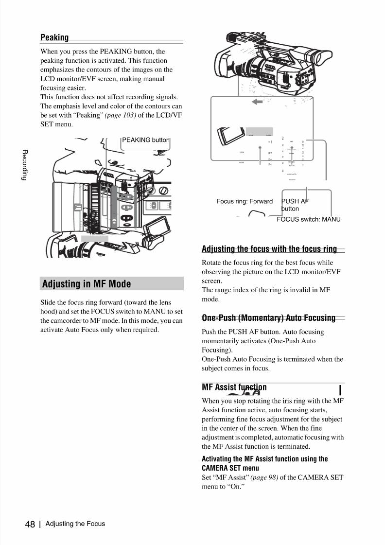
8/13/2019 Uputstvo Za Ex1
http://slidepdf.com/reader/full/uputstvo-za-ex1 48/132
Adjusting the Focus48
R e c or d i n g
Peaking
When you press the PEAKING button, the
peaking function is activated. This function
emphasizes the contours of the images on the
LCD monitor/EVF screen, making manual
focusing easier.
This function does not affect recording signals.The emphasis level and color of the contours can
be set with “Peaking” (page 103) of the LCD/VF
SET menu.
Slide the focus ring forward (toward the lens
hood) and set the FOCUS switch to MANU to set
the camcorder to MF mode. In this mode, you can
activate Auto Focus only when required.
Adjusting the focus with the focus ring
Rotate the focus ring for the best focus while
observing the picture on the LCD monitor/EVF
screen.
The range index of the ring is invalid in MF
mode.
One-Push (Momentary) Auto Focusing
Push the PUSH AF button. Auto focusing
momentarily activates (One-Push Auto
Focusing).
One-Push Auto Focusing is terminated when the
subject comes in focus.
MF Assist function
When you stop rotating the iris ring with the MF
Assist function active, auto focusing starts,
performing fine focus adjustment for the subject
in the center of the screen. When the fine
adjustment is completed, automatic focusing with
the MF Assist function is terminated.
Activating the MF Assist function using the
CAMERA SET menu
Set “MF Assist” (page 98) of the CAMERA SETmenu to “On.”
Adjusting in MF Mode
O F F
2
1
N D F IL T E R
ZEBRA PEAKING
GAIN
BAPRST
LMH
WHITE BAL
FULL AUTO
SLOT SELECT
OPEN
ACCESS
AB
1
2
3
AS S I G N
L E N S I N F O B R T D I S P H I S T O G R A M
MENU
CH-1
AUDIOLEVEL
CH-2
AUTO
MANU
AL
INT
EXT
PICTUR
E
PROFILE
PMW-E
X1
DCIN
CH-2
AUTO
MANU
AL
INT
EXT
CH-1
AUDIO
SELECT
AUDIO
IN
OFF
CAMERA
CANCEL
SEL / SE
T
MEDIA 1
5
2 5
4 0
8 1
. 2
1 0
3
1 0
5
1 0
3 0
1 5
5 .
8
M AN U AU T O
MA N U A U T O
FOCUS
I R I S
M AC R O
OFF ON
T H U M
B N A
I L
F R E V
P R E V
S E L / S E T
P L A Y / P A U S
E
S T O P
C A N C E L
F F W D
N E X T
R E C
S T A
R T / S T O
P
H O L D
R E C
R E V I E W
l
s
L
j
G / S
J M O N I T O R V O L
H L O F F
A
S H O T
T R A N S IT I O N
B
L C D B .L IG H T T C / U - B IT /
D U R A T I O N S T A T U S
B A R S / C A M
D I S P L A Y B A T T IN
F O
O N
O F F
ZEBRA PEAKING
GAIN
BA
PRST
LMH
WHITE BAL
FULL AUTO
PEAKING button
O F F
2
1
N D F IL T E R
ZEBRAPEAKING
GAIN
BA
PRST
LMH
WHITE BAL
FULLAUTO
SLOT SELECT
OPEN
ACCESS
AB
1
2
3
AS S I G N
L E N S I N F O B R T D I S P H I S T O G R A M
MENU
CH-1
AUDIOLEVEL
CH-2
AUTO
MANUA
L
INT
EXT
PICTUR
E
PROFIL
E
PMW-E
X1
DCIN
CH-2
AUTO
MANU
AL
INT
EXT
CH-1
AUDIO
SELECT
AUDIO
IN
OFF
CAMERA
CANCEL
SEL / SE
T
MEDIA 1
5
2 5
4 0
8 1
. 2
1 0
3
1 0
5
1 0
3 0
1 5
5 .
8
M AN U AU T O
MA N U A U T O
FOCUS
I R I S
M AC R O
OFF ON
T H U M B N A I L
F R E V
P R E V
S E L / S E T
P L A Y / P A U S E
S T O P
C A N C
E L
F F W
D
N E X T
R E C
S T A
R T / S T O
P
H O L D
R E C
R E V I E W
l
s
L
j
G / S
J M O N I T O R
V O L
H L O F F
A
S H O T
T R A N S IT I O N
B
L C D B .L I G H T T C / U -B I T /
D U R A T I O N
S T A T U S
B A R S /C A M
D I S P L A Y
B A T T I N F O
O N
O F F
OPEN
CLOSE
AF/MF Full MF
1 5
2 5
4 0
8 1 . 2
1 0
3
1 0
m m
5
1 0
3 0
f t
1 5
5 . 8
C
MANU AUTO
MANU AUTO
MACRO
FOCUS
PUSH AF
IRIS
OFF ON
8
5 . 6
4
2 . 8
1 . 9
1 6
Focus ring: Forward
FOCUS switch: MANU
PUSH AFbutton

8/13/2019 Uputstvo Za Ex1
http://slidepdf.com/reader/full/uputstvo-za-ex1 49/132
Adjusting the Focus 49
R e c or d i n g
Activating the MF Assist function using the Direct
menu
The current focus adjustment mode is displayed
on the screen when you press the DISPLAY/
BATT INFO button.
In MF mode, you can activate/deactivate the MF
Assist function with the Direct menu by operating
the joystick or jog dial.
When the function is active, an asterisk mark is
displayed to the right of the mode indication.
Note
The Direct menu cannot be selected in a modeother than MF mode.
For details on the Direct menu, see “Direct Menu
Operation” on page 19.
Slide the focus ring forward (toward the lens
hood) and set the FOCUS switch to AUTO to set
the camcorder to AF mode. In this mode, focus is
always adjusted automatically.
The range index of the ring is invalid in AF mode.
Focusing in AF mode
In AF mode the camcorder continuously checks
changes of images and activates auto focusing
each time it detects a change. The auto focus
adjustment is terminated when the subject comes
into focus, and the camcorder stands by until the
next change is detected.In AF mode, auto focusing is also activated when
you press the PUSH AF button or operate the
focus ring.
When you set the MACRO switch to ON in AF or
MF mode, Macro mode is activated, permitting
you to adjust the focus in a range that includes the
micro area.
The Macro mode is invalid in Full MF mode.
Adjusting in AF Mode
TLCS.
7 OnMF∗ATW 4300K PPOFF ND1 ++F1.9 18dB SHT:1/200
1 1.5 2 3 4 5 7 10 15 20 30 oo
OPEN
CLOSE
AF/MF Full MF
1 5
2 5
4 0
8 1 . 2
1 0
3
1 0
m m
5
1 0
3 0
f t
1 5
5 . 8
C
MANU AUTO
MANU AUTO
MACRO
FOCUS
PUSHAF
IRIS
OFF ON
8
5 . 6
4
2 . 8
1 . 9
1 6
Focus ring: Forward FOCUS switch:
AUTO
Using Macro Mode
OPEN
CLOSE
AF/MF Full MF
1 5
2 5
4 0
8 1 . 2
1 0
3
1 0
m m
5
1 0
3 0
f t
1 5
5 . 8
C
MANU AUTO
MANU AUTO
MACRO
FOCUS
PUSHAF
IRIS
OFF ON
8
5 . 6
4
2 . 8
1 . 9
1 6
MACRO switch

8/13/2019 Uputstvo Za Ex1
http://slidepdf.com/reader/full/uputstvo-za-ex1 50/132
Eliminating Picture Blurring (Steady Shot) / Reducing Flickers50
R e c or d i n g
By activating the Steady Shot function, blurring
of images due to camera shaking can be reduced.
Setting with the CAMERA SET menu
Set “Steady Shot” (page 101) of the CAMERA
SET menu to “On.”
Setting with the Direct menu
When you press the DISPLAY/BATT INFO
button, the setting of the Steady Shot function is
displayed on the screen.
You can turn it on/off with the Direct menu by
operating the joystick or the jog dial.
For details on the Direct menu, see “Direct Menu
Operation” on page 19.
Two operation modes are provided for Steady
Shot: Normal mode and Wide mode (for a wide
conversion lens).
When you attach the optional VCL-EX0877 wide
conversion lens, be sure to set “Wide
Conversion” (page 100) of the CAMERA SET
menu to “On.”
Note
If the camcorder is fixed to a tripod for stable
condition, deactivate the Steady Shot function.
To reduce flickers, try either of the following two
methods:
Setting the shutter speed according tothe power-supply frequency
Activate the electronic shutter (page 42) and set
the shutter speed according to the power supply
frequency.
When the frequency is 50 Hz
Set the shutter speed to 1 / 50 or 1 / 100 seconds.
When the frequency is 60 HzSet the shutter speed to 1 / 60 or 1 / 120 seconds.
Using the Flicker-Reduction function
Set “Flicker Reduce” (page 98) of the CAMERA
SET menu to “Auto” or “On” and set
“Frequency” to the power-supply frequency (50
Hz or 60 Hz).
Note
If the frame rate selected for recording is close tothe power-supply frequency, flicker may not be
reduced sufficiently even if you activate the
Flicker-Reduction function. In such cases, use the
electronic shutter.
Eliminating PictureBlurring (Steady Shot)
Note on use of a wide-conversion lens
TLCS.
7 On
MF∗
ATW 4300K PPOFF ND1 ++F1.9 18dB SHT:1/200
1 1.5 2 3 4 5 7 10 15 20 30 oo
Reducing Flickers

8/13/2019 Uputstvo Za Ex1
http://slidepdf.com/reader/full/uputstvo-za-ex1 51/132
Setting the Time Data 51
R e c or d i n g
Time data, such as the timecodes, user bits, and
the clock time, are recorded with pictures.
For the timecode, three running modes and Clock
mode can be selected.
Rec Run mode
The timecode advances during recording only.
The continuity of the timecode is maintainedbetween clips in the sequence of recording as long
as the SxS memory card is not changed.
If you remove the memory card and record on
another card, the timecode will not continue when
you return the first card to the slot again.
Free Run mode
The timecode keeps advancing regardless of
recording.
Regen mode
The timecode advances during recording only.
When you insert another memory card, the
camcorder starts next recording so that the
timecode continues to the last recorded timecode
on the card.
Clock mode
The current clock time is recorded for thetimecode.
Note
In Interval Recording, Frame Recording, Slow &
Quick Motion Recording, the timecode advances
in Rec Run mode regardless of the “Run” setting
if you set “Mode” of “Timecode” to “Preset.”
If you set it to “Clock,” the timecode advances in
Regen mode.
Specify the timecode to be recorded with
“Timecode” and “TC Format” of the TC/UB SET
menu.
For details on menu operations, see “Basic Menu
Operations” on page 94.
Setting the timecode to a desired value
1 Set “Mode” of “Timecode” to “Preset.”
2 Specify the timecode value on the
Setting line and select “SET.”
Resetting the timecode
You can reset the timecode to be recorded in
running modes to “00:00:00:00.”
1 Select “Reset” of “Timecode.”
2 Select “Execute.”
Using the actual time as the timecode
Set “Mode” of “Time Code” to “Clock.”
The time of the built-in clock is recorded as the
timecode.
Switching between DF and NDF of thetimecode
Using “TC Format” of the TC/UB SET menu, DF
(drop-frame mode) and NDF (non-drop frame
mode) of the timecode can be switched.
Note, however, that the mode is fixed either to DF
or NDF regardless of the TC Format setting,
depending on the current frame-rate setting.
Restrictions on the timecode
The timecode setting is restricted by the current
video format.
Setting the Time Data
Running Modes of the Timecode
Setting the Timecode
00:00
Return
Ti mecode
Users B i t
TC Format : DF
TC/UB SETReturn
Mode : Preset
Run : Rec Run
Set t ing : 00:00:00:00
Reset
B
B

8/13/2019 Uputstvo Za Ex1
http://slidepdf.com/reader/full/uputstvo-za-ex1 52/132
Setting the Time Data52
R e c or d i n g
1) The frame digits in “Setting” are limited to 00, 04, 08,
12, 16, and 20.
The frame at the beginning of recording is limited to
00, 04, 08, 12, 16, and 20.
The frame digits of the timecode added to the SDI
OUT connector output are changed to values in the
range of 00 to 29.
2) Even in Clock mode, the timecode may be gradually
shifted, because it is counted by NDF.
When adding the timecode to the output from the
COMPONENT OUT connector or the video output
from the A/V OUT connector, there may be a field that
has dual timecodes because of the 2-3 pull-down
process.
3) With DF, the frame digits can be set as desired in the
range of 00 to 29.
With NDF, the frame at the beginning of recording is
limited to 00, 05, 10, 15, 20, and 25.
You can add a hexadecimal number of 8 digits for
pictures as the user bits.
The user bits can also be set to the current date.
Use “Users Bit” of the TC/UB SET menu.
Setting eight digits as desired
1 Set “Mode” of “Users Bit” to “Fix.”
2 Specify the values on the Setting line
and select “SET.”
You can set hexadecimal digits A to F with
the corresponding alphabetics.
Recording the current date as the userbits
Set “Mode” of “Users Bit” to “Date.”
The current date is displayed on the Setting line.
In Camera mode, pressing the DISPLAY/BATT
INFO button displays the time data on the screen.
The indication is switched among the timecode,
user bits, and recording duration each time you
press the TC/U-BIT/DURATION button.
Video
formats
Frame
setting
TC Format
HQ1080/60i
SP 1080/60i
HQ1080/30P
00 to 29 DF/NDF switchable
(Fixed to DF in Clock
mode)
HQ 1080/50i
SP 1080/50i
HQ 1080/25P
00 to 24 Fixed to NDF
HQ 1080/24P
HQ 720/24P00 to 23 1) Fixed to NDF 2)
SP 1080/24P 00 to 29 3) DF/NDF switchable
(Fixed to DF in Clock
mode)
HQ 720/60P 00 to 29
(double count)
DF/NDF switchable
(Fixed to DF in Clock
mode)
HQ 720/50P 00 to 24
(double count)Fixed to NDF
HQ 720/30P 00 to 29 DF/NDF switchable
(Fixed to DF in Clock
mode)
HQ 720/25P 00 to 24 Fixed to NDF
Setting the User Bits
Displaying the Time Data
Display Contents
TCG **:**:**:** Tmecode
CLK **:**:**:** Timecode (Clock mode)
UBG ** ** ** ** User bits
DUR **:**:** Duration from the beginning of
recording
00:00
Return
Timecode
Users B i t
TC Format : DF
TC/UB SET
Return
Mode : Fix
S e t t i n g : 20 07 12 08
B
B
TCG 00:00:00:00
HQ 1080/24P
BY REC

8/13/2019 Uputstvo Za Ex1
http://slidepdf.com/reader/full/uputstvo-za-ex1 53/132
Recording Audio Signals 53
R e c or d i n g
Two channels (CH-1/CH-2) of audio can be
recorded (Linear PCM recording) insynchronization with video recording.
You can use the built-in stereo microphones
(omni-directional electret condenser
microphones) or 2-channel external audio inputs
to the AUDIO IN connectors by switching with
the AUDIO IN switches.
Set the AUDIO IN switches, both CH-1 and
CH-2, to INT.
1 Set the AUDIO IN switches CH-1 and
CH-2 to EXT.
2 Connect external audio sources to the
AUDIO IN connectors CH-1 and CH-2.
3 Set the LINE/MIC/+48V switches CH-1
and CH-2 to LINE (line level: +4 dBu).
You can use an external microphone for
recording, such as the ECM-673 Electret
Condenser Microphone.
1 Loosen the screw of the microphone
holder and open the cover.
2 Attach a microphone, close the
microphone holder cover for theoriginal condition to secure, then
connect the microphone cable to either
of the AUDIO IN connectors (CH-1 or
CH-2).
Recording Audio Signals
BATTERYRELEASE
SDI OUTA / V OUT
E X P A N D E D
F O C U S
R E C
R E V I E W
R E L E A S E
S T A R T /
S T O P
A
S H O T
T R A N S
I T I O N B
L C D B
. L I G H T T C / U - B I T /
D U R A T I O N
S T A T U S
B A R S / C A M
D I S P L A Y
B A T T I N F O
O N
O F F
P R E V
P L A
Y / P A U S
E
S T O P
C A N C E L
F F W
D
N E X T
R E C
S T A R T / S T O P
H O L D
l
s
L
j
G /
S J
H L O F F
T H U M B
N A I L
F R E V
S E L / S E T
M O N I T O
R V O L
A U D I O I N
C H - 1
M I C L I N E M I C + 4 8 V M I C L I N E
M I C + 4 8 V
C H - 2
AUTO
MANUAL
INT
EXTCH-2
AUTO
MANUAL
INT
EXTCH-1
AUDIO
SELECT
AUDIO
IN
CANCELSEL/SETMENU
CH-1
AUDIO
LEVEL
CH-2
AUDIO IN
CH-1
MIC
LINE MIC+48V
MIC
LINE MIC+48V
CH-2
AUDIO IN switches:To select the source
LINE/MIC/+48Vswitches:To select the type ofexternal source
AUDIO SELECT switches:To select the recording leveladjustment mode
Built-in stereo microphones
AUDIO INconnectors:To input externalsources
AUDIO LEVEL controls:To adjust the recording levels
Using the Built-in StereoMicrophones
Using External Inputs
Using an External Microphone
E X P A N
F O C U S
R E C
R E V I E W
R E L E A S E
S T A R T /
S T O
P
A
S H O T T R A N S I T I O N
B
L C D B .
L I G H T O N
O F F
P R E V
P L A Y
/ P A U S E
S T O P
C A N C E L
F F W
D
N E X T
R E C
S T A R T / S T O P
H O L D
l
s
L
j
G / S
J
H L O F F
T H U M
B N A I L
F R E V
S E L / S E T
M O N I T O
R V O
L
A U D I O I N
C H - 1
M I C L I N E M I C + 4 8 V M I C L I N E
M I C + 4 8 V
C H - 2

8/13/2019 Uputstvo Za Ex1
http://slidepdf.com/reader/full/uputstvo-za-ex1 54/132
Recording Audio Signals54
R e c or d i n g
3 Set the corresponding AUDIO INswitch (CH-1 or CH-2) to EXT.
4 Set the corresponding LINE/MIC/+48V
switch (CH-1 or CH-2) according to the
connected microphone.
MIC: For a microphone that requires no
power supply
+48V: For a microphone that requires +48V
power supply (such as the ECM-673)
You can select automatic or manual adjustment
mode independently for each channel.
To adjust the levels automatically (AGC)
When the AUDIO SELECT switches CH-1 and
CH-2 are set to AUTO, the audio recording levelsare automatically adjusted.
To adjust the levels manually
Set the AUDIO SELECT switches CH-1 and CH-
2 to MANUAL, and adjust the audio recording
levels by turning the AUDIO LEVEL controls.
The value is set to 0 dB when the control is set to
5. Setting to 10 maximizes the level (+12 dB) and
setting to 0 minimizes it (–∞).
The input levels are displayed on the screen when
you press the DISPLAY/BATT INFO button.
Audio recording in special recording
modes• No audio recording is made in Interval
Recording or Frame Recording.
• No audio recording is made in Slow & Quick
recording if the recording frame rate is set to a
value different from the playback frame rate.
You can monitor the sounds being recorded withthe headphones connected to the headphone
connector (stereo mini jack).
Note
The built-in speaker is disabled in Camera mode.
To adjust the audio monitoring volume
Use the MONITOR VOL buttons.
Pressing the + button increases the volume, and
pressing the – button decreases it. To muffle the
sound, set it to the minimum level.
While you adjust the volume, the level is
displayed as a bar on the screen.
Adjusting the Audio RecordingLevels
E X P
A N D E
F O C
U S
R E C
R E V I E W
R E L E A S
E
S T A R T /
S T O P
A
S H O T T R A N S I T I O N
B
L C D B . L I G H T B R
O N
O F F
P R E V
P L A
Y / P A
U S E
S T O P
C A N C E L
F F W
D
N E X T
R E C
S T A R T / S T O P
H O L D
l
s
L
j
G / S
J
H L O F F
T H U M B N A I L
F R E V
S E L / S E T
M O N I T O
R V O L
A U D I O I N
C H - 1
M I C L I N E M I C + 4 8 V M I C L I N E
M I C + 4 8 V
C H - 2
A U D I O I N
C H - 1
M I C L I N E M I C + 4 8 V M I C L IN E
M IC + 4 8 V
C H - 2
1
2
4
3
Externalmicrophone
to AUDIO IN
Cable clamp
Monitoring the Audio
ND1 ++F1.9 18dB SHT:1/2000
1 1.5 2 3 4 5 7 10 15 20 30 oo m
CH1CH2
AUTOMANUAL INT
EXT
PICTUREPROFILE
PMW-EX1
DC IN
CH-2
AUTOMANUAL INT
EXT
CH-1
AUDIOSELECT AUDIOIN
OFFCAMERA
CANCEL
SEL /SET
MEDIA
BATTERY
RELEASE
A / V OU
TCO
MPONE
NT
OUT
SDI OU
T
T H U M B N A I L
F R E V
P R E V
S E L / S E T
P L A Y / P A U S E
S T O P
C A N C E L
F F W D
N E X T
R E C S T A R T / S T O P
H O L D
l
s L
j G / S J
M O N I T O R V O L
H L O
F F
S H O
T
T R A N S I T I O
N
B
A
B . L I G
H T
T C / U
- B I T
/
D U R A T
I O N
S T A T U
S
B A R
S / C A M
D I S
P L A Y
B A T T I N
F O
O N
O F F
AU D IO IN
C H - 1
M I C
LI N E M I C + 4
8 V
M I C
LI N E M IC +
4 8 V
C H - 2
R E L E A S E
MONITOR VOL
HDV
Headphoneconnector MONITOR VOL buttons

8/13/2019 Uputstvo Za Ex1
http://slidepdf.com/reader/full/uputstvo-za-ex1 55/132
Outputting the Color Bars and Reference Tone / Recording Shot Marks 55
R e c or d i n g
The camcorder can output a color-bar signal in
place of the camera picture.
A 1-kHz reference tone is output with the color
bar signal if “1kHz Tone” of “Audio Input” (page
101) is set to “On” with the AUDIO SET menu.
The color-bar signal and reference-tone signal are
also fed out from the SDI OUT, COMPONENT
OUT, and A/V OUT connectors.
Press the BARS/CAM button.
The camera picture is switched to color bars.
To return to the camera picture, press the button
again.
You can select the type of color bars with “ColorBar Type” (page 98) of the CAMERA SET menu.
Multi: ARIB multiformat color bars
75%: Vertical stripes of 75% luminance
100%: Vertical stripes of 100% luminance
Notes
• When recording of the camera image is in
progress, it cannot be switched to the color-bar
picture even if you press the BARS/CAM
button. (You can switch the color-bar picture to
the camera picture.)• The color bar mode cannot be selected in Slow
& Quick Motion mode and EX Slow Shutter
mode.
When you record shot marks for important scenes
as subsidiary data, you can access the markedpoints easily on a Shot Mark screen, which only
displays scenes with shot marks only. This
increases editing efficiency.
For the Shot Mark Screen, see “Displaying the
SHOT MARK Screen” on page 85.
The camcorder permits you to record two types of
shot marks: shot mark 1 and shot mark 2.
Shot marks can be recorded as needed during
recording or can be added after recording whilechecking the playback pictures.
Inserting a shot mark during recording
Activate the IR Remote Commander (page 27),
and use the SHOTMARK 1 or 2 button.
Press the SHOTMARK 1 or 2 button where
you wish to insert a mark.
If the Shot Mark1 or Shot Mark2 function is
assigned to an assignable button, you can also use
it instead (page 56).
A shot mark of the type corresponding to thebutton you press is recorded.
For operations to add shot marks after recording,
see “Adding shot marks during playback” on page
80 and “Adding/Deleting Shot Marks” on page 86 .
Outputting the ColorBars and ReferenceTone
O F F
2
1
N D F I LT E R
ZEBRAPEAKING
GAIN
BA
PRST
LMH
WHITE BAL
FULLAUTO
SLOT SELECT
OPEN
ACCESS
AB
1
2
3
AS S IG N
L E N S I N F O B R T D I S P H I S T O G R A M
MENU
CH-1
AUDIOLEVEL
CH-2
AUTO
MANUA
L
INT
EXT
PICTUR
E
PROFILE
PMW-E
X1
DCIN
CH-2
AUTO
MANUA
L
INT
EXT
CH-1
AUDIO
SELECT
AUDIO
IN
OFF
CAMERA
CANCEL
SEL / SE
T
MEDIA 1
5
2 5
4 0
8 1
. 2
1 0
3
1 0
5
1 0
3 0
1 5
5 .
8
M AN U AU T O
MA N UA U T O
FOCUS
I R I S
M AC R O
OFF ON
T H U
M B N A I L
F R E V
P R E V
S E L / S E T
P L A Y / P A U S E
S T O P
C A N C
E L
F F W
D
N E X T
R E C
S T A
R T / S T O
P
H O L D
R E C
R E V I E W
l
s
L
j
G / S
J M O N I T O R
V O L
H L O F F
A
S H O T
T R A N S I T IO N
B
L C D B .L I G H T T C / U -B I T /
D U R A T I O N S T A T U S
B A R S /C A M
D I S P L A Y
B A T T I N F O
O N
O F F
A
SHOT
TRANSITION
B
LCD B.LIGHT
TC/U-BIT/
DURATION STATUS
BARS/CAMDISPLAY
BATT INFOON OFF
BARS/CAM button
Recording Shot Marks
1
2
T
ZOOM
PUSH SET
SHOTMARK
SUB CLIPTHUMBNAIL
PLAY/PAUSE STOP
W
. > xu
PREV NEXT
SHOTMARK 1 button
SHOTMARK 2 button

8/13/2019 Uputstvo Za Ex1
http://slidepdf.com/reader/full/uputstvo-za-ex1 56/132
Rec Review / Changing Functions of the Assignable Buttons56
R e c or d i n g
You can review the last recorded clip on the
screen (Rec Review).
Press the REC REVIEW button after
recording is finished.
You can assign the Rec Review function to an
assignable button to use it instead (page 56).
Playback of the specified block of the clip begins.
In Rec Review, the last 3 seconds, 10 seconds, or
the entire part of the clip is displayed, depending
on the “Rec Review” setting (page 99) of the
CAMERA SET menu. It is set to 3 seconds at the
factory.
Rec Review is terminated at the end of the clip,
resuming STBY (recording standby) status.
Notes
• If the duration of the last recorded clip is less
than the time (3 or 10 seconds) specified for Rec
Review, the clip is played back from the
beginning to the end.
• During Rec Review playback, only the STOP
button is valid.
When the STOP button is pressed, Rec Review
is canceled, and the camcorder returns to STBY
(recording standby) status.
• If the video format is changed after recording,Rec Review cannot be performed.
• The Setup and PICTURE PROFILE menus
cannot be operated during Rec Review.
The camcorder has four assignable buttons to
which you can assign various functions forconvenience.
The following functions are assigned at the
factory:
ASSIGN 1 button (LENS INFO)
Depth-of-field indication on/off
ASSIGN 2 button (BRT DISP)
Brightness-level indication on/off
ASSIGN 3 button (HISTOGRAM)
Histogram indication on/off
ASSIGN 4 button
No function is assigned (Off).
Changing Functions
Use “Assign Button” of the OTHERS menu.
For details on menu operations, see “Basic Menu
Operations” on page 94.
1 Select “Assign Button” from the
OTHERS menu.
Rec Review
BATTERYRELEASE
SDI OUTA /VOUT
E X P A N D E D
F O C U S
R E C
R E V I E W
R E L E A S E
S T A R T /
S T O P
A
S H O T
T R A N S I T I O N
B
L C D B . L I G H T T C / U - B I T /
D U R A T I O N
S T A T U S
B A R S / C A M
D I S P L A Y
B A T T I N F O
O N
O F F
P R E V
P L A Y / P A
U S E
S T O P
C A N C E L
F F W
D
N E X T
R E C
S T A R T / S T O P
H O L D
l
s
L
j
G / S
J
H L O F F
T H U M B N A I L
F R E V
S E L / S E T
M O N I T O
R V O L
A U D I O I N
C H - 1
M I C L I N E M I C + 4 8 V M I C L I N E
M I C + 4 8 V
C H - 2
E X P A N D E D
F O C U S
R E C
R E V I E W
R E L E A S E
S T A R T /
S T O P
REC REVIEWbutton
Changing Functions ofthe Assignable Buttons
O F F
2
1
N D F IL T E R
ZEBRA PEAKING
GAIN
BAPRST
LMH
WHITE BAL
FULL AUTO
SLOT SELECT
OPEN
ACCESS
AB
1
2
3
AS S I G N
L E N S IN F O B R T D I S P H IS T O G R A M
MENU
CH-1
AUDIOLEVEL
CH-2
AUTO
MANUA
L
INT
EXT
PICTUR
E
PROFIL
E
PMW-E
X1
DCIN
CH-2
AUTO
MANUA
L
INT
EXT
CH-1
AUDIO
SELECT
AUDIO
IN
OFF
CAMERA
CANCEL
SEL / SE
T
MEDIA 1
5
2 5
4 0
8 1
. 2
1 0
3
1 0
5
1 0
3 0
1 5
5 . 8
M AN U AU T O
MA N U A U T O
FOCUS
I R I S
M AC R O
OFF ON
T H U M
B N A I L
F R E V
P R E V
S E L / S E T
P L A Y / P A U S
E
S T O
P
C A N
C E L
F F W D
N E X T
R E C
S T A R T / S T O P
H O L D
R E C
R E V I E W
l
s
L
j
G / S
J M O N I T O R V O L
H L O F F
A
S H O T T R A N S
IT I O N B
L C D B .L IG H T T C /U - B IT /
D U R A T IO N S T A T U S
B A R S / C A M
D I S P L A Y B A T T IN F O
O N
O F F
ASSIGN 4 OFF ON
SHUTTER
WHT BAL
1 2 3
ASSIGN
LENS INFO BRT DISP HISTOGRAM
ASSIGN 1 to 3 buttons
ASSIGN 4 button

8/13/2019 Uputstvo Za Ex1
http://slidepdf.com/reader/full/uputstvo-za-ex1 57/132
Interval Recording 57
R e c or d i n g
2 Select the button to which you wish to
assign a function.
3 Select the function to be assigned.
4 Exit the menu.
The assigned functions can be viewed on the
BUTTON/REMOTE status screen (page 91).
The Interval Recording (time-lapse recording)
function is especially effective for shootingobjects that move very slowly.
The specified number of frames are automatically
recorded at the specified intervals.
It is recommended to fix the camcorder to a tripod
or equivalent and use the IR Remote Commander
to start/stop recording rather than pressing theREC START/STOP button of the camcorder.
Notes
• Interval Recording cannot be set to “On”
simultaneously with Frame Recording or Slow
& Quick Motion. When you set Interval
Recording to “On,” Frame Recording and Slow
& Quick Motion are forcibly set to “Off.”
• No audio recording is executed in Interval
Recording.
• Interval Recording cannot be performed if anSP video format is selected with “Video
Format” and “i.LINK I/O” is set to “Enable”
with the OTHERS menu.
• Interval Recording cannot be performed if
“Video Format” of the OTHERS menu is set to
SP 1080/24P.
Before starting Interval Recording, make the
necessary settings on the CAMERA SET menu in
advance.
Function Contents
Marker All marker indications (safety-
zone marker, center marker,
aspect marker, guide frames) on/
off
Last Clip DEL Last clip delete
ATW ATW function on/off
Rec Review Rec Review start/stop
Rec Recording start/stop
Freeze Mix Freeze Mix start/stop
Expanded
Focus
Expanded Focus function on/off
Spotlight TLCS Spotlight mode on/off
Backlight TLCS Backlight mode on/off
IR Remote IR Remote Commander enable/
disable
Shot Mark1 Shot mark 1 insert
Shot Mark2 Shot mark 2 insert
Fader Fader on/off
EVF Mode EVF screen mode (color/
monochrome) switching
BRT Disp Brightness level indication on/off
Histogram Histogram indication on/off
Lens Info Depth-of-Field indication on/off
00:00
Return
<1> : Freeze M ix
<2> : Shot Mark1
<3> : Shot Ma r k 2
<4> : Rec Review
OTH ERS
A l l Reset
Camera Data
Time Zone : UTC +09:00
Clock Set
Language : Engl ish
Assign Button
T a l l y
B
B
B
B
Interval Recording
Preparatory Settings
Number of frames for one recording session(Number of Frames)
Recording interval (Interval Time)

8/13/2019 Uputstvo Za Ex1
http://slidepdf.com/reader/full/uputstvo-za-ex1 58/132
Interval Recording58
R e c or d i n g
For details on menu operations, see “Basic Menu
Operations” on page 94.
1 Select “Interval Rec” of the CAMERA
SET menu.
2 Set “Setting” to “On.”
The camcorder enters Interval Recording
mode.
When the special recording mode indication
on the screen is active, “Interval Rec” flashes
on the screen.
3 Set the time between recordings with
“Interval Time.”
You can select the time from among 1 to10/
15/20/30/40/50 seconds, 1 to 10/15/20/30/
40/50 minutes, and 1 to 4/6/12/24 hours by
scrolling the display.
4 Set the number of frames to be recordedat a time with “Number of Frames.”
When “Video Format” (page 108) is set to
“720/60P” or “720/50P,” you can select from
among 2, 6, and 12 frames.
With other settings, you can select from
among 1, 3, 6, and 9 frames.
5 Exit the menu.
When the preparatory settings are completed, you
can start recording.
Press the REC START/STOP button.
Interval Recording begins.
The flashing “Interval Rec” on the screen is now
steadily lit.
Notes
• You cannot change the “Interval Time” and“Number of Frames” settings while Interval
Recording is in progress. To change them,
pause recording.
• The Freeze Mix function and Rec Review
function cannot be used in Interval Recording
mode.
• The timecode is recorded in Rec Run mode
(page 51) during Interval Recording.
• Some extra frames may be recorded if you stop
recording or switch the card slot while
recording is halted in Interval Recording mode.
Stopping Interval Recording
Press the REC START/STOP button.
Interval Recording stops.
To restart Interval Recording, press the button
again.
Canceling Interval Recording mode
Set “Setting” of “Interval Rec” of the CAMERA
SET menu to “Off.”
Notes
It automatically returns to “Off” when you set the
power switch to OFF, while the “Interval Time”
and “Number of Frames” settings are maintained.
Performing Interval Recording
00:00
Shot Tran si t ion
MF As s i s t
:
O f f
Color Bar Type : Mul t i
F l i c k e r Reduce
Zoom Speed
I n t e r v a l Rec
Frame Rec
CAMERA SET
Return
Set t i ng
I n t e r v a l T ime
Number of Frames
: O f f
: 1sec
: 1
B
B
B
B
B
B

8/13/2019 Uputstvo Za Ex1
http://slidepdf.com/reader/full/uputstvo-za-ex1 59/132
Frame Recording 59
R e c or d i n g
The Frame Recording function is especially
effective for clay animation recording.The specified number of frames are recorded
intermittently when you press the REC START/
STOP button.
It is recommended to fix the camcorder to a tripod
or equivalent and use the IR Remote Commander
to start/stop recording rather than pressing the
REC START/STOP button of the camcorder.
Notes
• Frame Recording cannot be set to “On”
simultaneously with Interval Recording or Slow
& Quick Motion. When you set Frame
Recording to “On,” Interval Recording and
Slow & Quick Motion are forcibly set to “Off.”
• No audio recording is executed in Frame
Recording.
• Frame Recording cannot be performed if an SP
video format is selected with “Video Format”
and “i.LINK I/O” is set to “Enable” with the
OTHERS menu.
• Frame Recording cannot be performed if“Video Format” of the OTHERS menu is set to
SP 1080/24P.
Before starting Frame Recording, make the
necessary settings on the CAMERA SET menu in
advance.
For details on menu operations, see “Basic Menu
Operations” on page 94.
1 Select “Frame Rec” of the CAMERA
SET menu.
2 Set “Setting” to “On.”
The camcorder enters Frame Recording
mode.
When the special recording mode indication
on the screen is active, “Frame Rec” flashes
on the screen.
3 Select the “Number of Frames” value
for one recording session.You can select from among 2, 6, and 12 when
“Video Format” is set to 720/60P or 720/50P.
With other video formats, you can select
from among 1, 3, 6, and 9.
4 Exit the menu.
When the preparatory settings are completed, you
can start recording.
1 Press the REC START/STOP button.
Recording in Frame Rec mode begins.
The “Frame Rec” indication stops flashing.
When the number of frames you specified
with the menu are recorded, the camcorder
automatically enters FRM STBY (Frame Rec
Standby) status.
2 Press the REC START/STOP button
again.
Each time you press the REC START/STOP
button, the camcorder records the specified
number of frames then enters FRM STBY
status.
Notes
• Recording cannot be stopped until the specified
number of frames are recorded. If the power
switch is set to OFF during recording, the power
is only shut off after the specified number of
frames are recorded.
• The Freeze Mix function and Rec Review
function cannot be used while recording in
Frame Rec mode is in progress.
• You cannot change the “Number of Frames”
setting while recording in Frame Rec mode is in
progress. To change it, pause the recording.
• The timecode is recorded in Rec Run mode
(page 51) during Frame Recording.• Some extra frames may be recorded if you stop
recording or switch the card slot while
recording is paused in Frame Rec mode.
Frame Recording
Preparatory Settings
00:00 Return
S e t t i ng
Number
of
Fr ames
MF As s i s t : O f f
Color Bar Type : Mul t i
F l i c k e r Reduce
Zoom Speed
I n t e r v a l Rec
Frame Rec
S&Q Mo t i on
: O f f
: 1
CAMERA SET
B
B
B
B
B
B
Performing Frame Recording

8/13/2019 Uputstvo Za Ex1
http://slidepdf.com/reader/full/uputstvo-za-ex1 60/132
Slow & Quick Motion Recording60
R e c or d i n g
Stopping Frame Recording
Set “Setting” of “Frame Rec” of the
CAMERA SET menu to “Off.”
Recording stops and Frame Rec mode is
canceled.
Notes
It automatically returns to “Off” when you set the
power switch to OFF, while the “Number of
Frames” setting is maintained.
When an HQ Progressive (P) video format is
selected (page 35), you can set the frame rate forrecording different from that for playback.
By recording at the different frame rate, you can
obtain smoother slow-motion or quick-motion
effect when compared with slow-speed or fast-
speed playback of a material recorded at the
normal recording speed.
Example
When the video format is HQ 720/24P, recording
with a frame rate between 1 and 23 fps provides a
quick-motion effect in playback, and recordingwith the frame rate between 25 and 60 fps
provides a slow-motion effect in playback.
Notes
• Slow & Quick Motion cannot be set to “On”
simultaneously with Frame Recording or
Interval Recording. When you set Slow &
Quick Motion to “On,” Frame Recording and
Interval Recording are forcibly set to “Off.”
• No audio recording is made if the recording
frame rate is set to a value different from the
playback frame rate.
• Slow & Quick Motion recording cannot be
made if “Video Format” of the OTHERS menu
is set to HQ1080/60i, HQ1080/50i, SP1080/60i,
SP1080/50i, or SP1080/24P.
Before starting Slow & Quick Motion recording,
make the necessary settings with the CAMERA
SET menu in advance.
For details on menu operations, see “Basic Menu
Operations” on page 94.
1 Select “S&Q Motion” from the
CAMERA SET menu.
Slow & Quick MotionRecording
Preparatory Settings

8/13/2019 Uputstvo Za Ex1
http://slidepdf.com/reader/full/uputstvo-za-ex1 61/132
Slow & Quick Motion Recording 61
R e c or d i n g
2 Set “Setting” to “On.”
The camcorder enters Slow & Quick Motion
mode.
When the special recording mode indication
on the screen is active, “S&Q Motion” is
displayed on the screen.
3 Select the frame rate for recording with
“Frame Rate.”
The setting range varies depending on the
current video format.
With a 1080 format: 1 to 30 fps
With a 720 format: 1 to 60 fps
4 Exit the menu.
Setting the recording frame rate with theDirect menu
When the special recording mode indication on
the screen is active, [Recording frame rate]/
[Playback frame rate] fps is displayed under
“S&Q Motion.”
You can change the recording frame rate with the
Direct menu by operating the joystick or the jogdial.
For details on the Direct menu, see “Direct Menu
Operation” on page 19.
When the preparatory settings are completed, you
can start recording.
Press the REC START/STOP button.
Slow & Quick Motion recording begins.
Notes
• You cannot change the Frame Rate setting
while Slow & Quick Motion recording is in
progress. To change it, pause the recording.
• The timecode is recorded in Rec Run mode
during Slow & Quick Motion recording (page
51).
Stopping recording
Press the REC START/STOP button.
Slow & Quick Motion recording stops.
Note
When recording at a low-speed frame rate, it may
take time until recording stops after you press the
REC START/STOP button.
Canceling Slow & Quick Motion mode
Set “Setting” of “S&Q Motion” of the CAMERA
SET menu to “Off.”
Note
It automatically returns to “Off” when you set the
power switch to OFF, while the “Frame Rate”
setting is maintained.
Recording in Slow & Quick MotionMode
00:00 Return
Se t t i ng
Frame Rate
Color Bar Type : Mu l t i
F l i c k e r Reduce
Zoom Speed
I n t e r v a l Rec
Frame Rec
S&Q Mo t i on
Rec Review
: O f f
: 30
CAMERA SET
B
B
B
B
B
B
B
TCG 00:00:00:00HQ 1080/24P
S&Q Motion29/24fps
BY S&Q STBY

8/13/2019 Uputstvo Za Ex1
http://slidepdf.com/reader/full/uputstvo-za-ex1 62/132
Freeze Mix: Image Alignment62
R e c or d i n g
Using the Freeze Mix function, an image (still
picture) of a recorded clip can be temporarilysuperimposed on the current camera picture,
permitting you to easily align images for next
recording.
To use the Freeze Mix function
Assign the Freeze Mix function to one of the
assignable buttons.
For details, see “Changing Functions of the
Assignable Buttons” on page 56 .
Superimposing a Freeze Mix image
1 Stop recording to set the camcorder to
STBY (recording standby) status.
2 Press the REC REVIEW button to
review the recorded images, or press the
ASSIGN button to which you assigned
“Freeze Mix.”
3 Press the ASSIGN button to which you
assigned “Freeze Mix” at the image
with which you want align.
The image where you pressed the ASSIGN button
in step 3 is displayed as a still picture over the
current camera picture.
Canceling Freeze Mix status
You can cancel it with the ASSIGN button to
which you assigned “Freeze Mix” or the REC
START/STOP button.
• When you cancel Freeze Mix status by pressing
the ASSIGN button, the normal camera picture
is restored.
• When you cancel Freeze Mix status by pressing
the REC START/STOP button, normal
recording begins.
Notes
• If the recorded picture and the current camera
picture differ in video format, the Freeze Mix
display cannot be achieved.
• The Freeze Mix function cannot be used if the
recording video format is SP 1080/24P.
• The Freeze Mix display cannot be obtained in
Quick & Slow Motion mode or Slow Shutter
mode.
• You cannot operate the Setup menus and
PICTURE PROFILE menu in Freeze Mix
status.
Freeze Mix: ImageAlignment

8/13/2019 Uputstvo Za Ex1
http://slidepdf.com/reader/full/uputstvo-za-ex1 63/132
Shot Transition 63
R e c or d i n g
The Shot Transition function helps you to easily
obtain complex picture effects by registeringcamera settings or conditions as a “shot” to be
reproduced in a recording sequence.
Your settings for focus, zoom, iris, gain, shutter
speed, white balance, color matrix, and detail
level can be registered in combination in one shot,
and you can change the current camera settings to
those of the shot, or the settings reproduced from
one shot to those of another Shot, resulting in a
smooth transition of scenes.
For example, you can shift the focus from a closer
object to a farther object, or change the depth of
field by adjusting the iris. In addition, you can
develop scenes under different recording
conditions smoothly. If you register the manual
adjustment function for white balance, the scenes
will develop smoothly between objects indoors
and those outdoors.
Notes
• Shot transition cannot be activated in
combination with any of the EX Slow Shutter,Interval Recording, Frame Recording, and Slow
& Quick Motion functions.
• If you wish to shift the focus in a shot transition,
set the focus adjustment mode to MF or AF (see
page 47). The focus will not be shifted if Full
MF mode is selected.
• If you wish to shift the zoom in a shot transition,
set the ZOOM switch to SERVO (see page 45).
The zoom will not be shifted with the MANU
setting.
• If you register a focus position in a macro area
with the MACRO switch ON, the focus may not
be shifted to the registered position if a shot
transition is executed with the MACRO switch
set to OFF.
Shot-transition operation buttons andindications
For shot-transition operations, use the three
TRANSITION operation buttons on the upperpanel.
A button and B button
You can register a Shot to each of the buttons.
MODE button and indicator
When you press this button, the camcorder enters
Shot Transition operation mode, and the indicator
of the button lights.
The shot transition operation area is displayed on
the screen.
Each time you press the button, the shot-transition
operation mode cycles among Store, Check,
Execute, and Off (normal Camera mode).
In Execute mode, the shot transition information
area appears.
Note
Camera operations are disabled when the shot
transition operation mode is Check or Execute.
Shot Transition
O F F
2
1
N D F IL T E R
ZEBRAPEAKING
GAIN
BA
PRST
LMH
WHITE BAL
FULL AUTO
SLOT SELECT
OPEN
ACCESS
AB
1
2
3
AS S I G N
L E N S I N F O B R T D I S P H I S T O G R A M
MENU
CH-1
AUDIOLEVEL
CH-2
AUTO
MANUA
L
INT
EXT
PICTUR
E
PROFILE
PMW-E
X1
DCIN
CH-2
AUTO
MANUA
L
INT
EXT
CH-1
AUDIO
SELECT
AUDIO
IN
OFF
CAMERA
CANCEL
SEL / SE
T
MEDIA 1
5
2 5
4 0
8 1
. 2
1 0
3
1 0
5
1 0
3 0
1 5
5 .
8
M AN U AU T O
MA N U A U T O
FOCUS
I R I S
M AC R O
OFF ON
T H U
M B N A I L
F R E V
P R E V
S E L / S E T
P L A Y / P A U S E
S T O P
C A N C
E L
F F W
D
N E X T
R E C
S T A
R T / S T
O P
H O L D
R E C
R E V I E W
l
s
L
j
G / S
J M O N I T O
R V O L
H L O F
F
A
S H O T
T R A N S I T IO N
B
L C D B .L I G H T T C / U -B I T /
D U R A T I O N
S T A T U S
B A R S /C A M
D I S P L A Y
B A T T I N F O
O N
O F F
A
SHOT
TRANSITION
B
LCD B.LIGHT
TC/U-BIT/
DURATION STATUS
BARS/CAMDISPLAY
BATT INFOON OFF
MODE button andindicator
A button B button
TCG 00:00:00:00
Shot Transit ionExecute
Shot-A
Shot-B
S E
0s 12 s Rec Link: Of f
REC
Shot-transition operation area
Shot-transition information area

8/13/2019 Uputstvo Za Ex1
http://slidepdf.com/reader/full/uputstvo-za-ex1 64/132
Shot Transition64
R e c or d i n g
When adjustments are required, set the mode to
Store.
Before you start recording using the Shot
Transition function, make the necessary settingswith the CAMERA SET menu in advance.
The conditions you set are indicated in the shot
transition information area on the screen when
you set the shot-transition operation mode to
“Execute.”
Shot-transition information area
Setting procedure
1 Select “Shot Transition” from the
CAMERA SET menu.
2 Specify the conditions for a shot
transition.
Trans Time
After you set “Time/Speed” to “Time,” set
the duration of a transition in the range of 2
to 15 sec in steps of 1 second.
Trans Speed
After you set “Time/Speed” to “Speed,” set
the zoom transition speed (specifying the
time to be taken for the zoom moving from
the TELE end to the WIDE end at a certain
speed).The setting range is from 1 to 10. The larger
the number you set, the higher speed.
Time/Speed
Set whether to specify the duration of a
transition by time or by speed of zoom
transition.
Trans Curve
Select the transition pattern.
The corresponding icon is displayed in the
shot transition information area.
P: Parameter level T: Transition of time
Start Timer
Set the time from start of recording to start of
the shot transition.
The countdown indication is displayed in the
shot-transition information area until the shot
transition is started by the Start Timer.
Rec Link
Set whether to link shot-transition start and
target shot selection to recording start.
The setting status is displayed in the shot
transition information area.
Preparatory Settings
S E
0s 12 s
Rec Link : Of f
Progress bar
Transition pattern
Transition time
Rec Link status
Start timer indication
00:00
CAMERA SETReturn
Trans Time
Trans Speed
Time/Speed
Trans Curve
S t a r t Timer
Rec Link
: 2sec
: 5
: Speed
: Soft Stop
: Of f
: Of f
Return
Gain Setup
Shut te r
EX S lo w Shut ter
Shot Trans i t ion
MF As s i s t : O f f
Color Bar Type : M u l t iB
B
B
B
B
Setting Contents
Time The “Transition Time” setting is valid.
Speed The “Transition Speed” setting is
valid.
Setting
and icon
Contents
Linear To make the transition linearly.
Soft Trans To make the transition slowly at
the beginning and end but linearly
in between.
Soft Stop To make the transition slowly near
the end.
T
P
T
P
T
P

8/13/2019 Uputstvo Za Ex1
http://slidepdf.com/reader/full/uputstvo-za-ex1 65/132
Shot Transition 65
R e c or d i n g
Off: Not to link to recording start
(To use the A or B button to start the
transition and specify the target shot)
Shot-A: To start the transition to Shot A in
synchronization with recording start
Shot-B: To start the transition to Shot B in
synchronization with recording start
3 Exit the menu to finish the settings.
Registering a shot
You can register two kinds of shots: A and B.
1 Press the MODE button to display
“Store” in the shot-transition operation
area.
2 Adjust the camera settings to obtain animage you wish to register.
3 When adjustment is finished, press the
Shot A or Shot B button.
The camera settings are registered to the pressed
button.
The registered camera settings are maintained
until you register them next.
Checking the Registered Settings (Shot)
1 Press the MODE button to display
“Check” in the shot-transition
operation area.
2 Press the A or B button, whichever you
assigned to the shot you wish to check.
The selected shot (camera settings or conditions)takes effect on the picture on the screen.
With this operation, you cannot check the
conditions of the transition.
When the preparatory settings are completed, you
can start recording.
Operations differ depending the “Rec Link”
setting.
Making a transition from the currentpicture to a registered shot
1 Adjust the camera settings to obtain an
image with which you wish to start
recording.
2 Press the MODE button to display
“Execute” in the shot-transition
operation area.
3 Press the REC START/STOP button.
Recording begins.
4 When “Rec Link” is “Off,” press the
button of the target shot (A or B) when
you wish to start the shot transition.The current camera settings are gradually
shifted to those registered to the specified
shot.
When “Rec Link” is “Shot-A” or “Shot-
B,” the camcorder automatically performs
the shot transition to the camera settings
registered to Shot A or Shot B, respectively.
You need not press the button.
Notes
• You cannot return to the status in step 1 onceafter you start the shot transition. If the status
must be resumed, register it as a shot.
• When you perform recording on an external
device connected via the i.LINK(HDV)
connector in synchronization with REC
START/STOP operations on this camcorder,
recording start on the external device and shot-
transition start may not be synchronized even if
“Rec Link” has been set to “Shot-A” or “Shot-
B,” depending on the performance of theexternal device.
Making a transition from Shot A to Shot B
When “Rec Link” is set to “Off” or “Shot-B,” a
shot transition from Shot A to Shot B is possible.
1 Press the MODE button to display
“Check” in the shot-transition
operation area.
2 Press the A button.
The picture is adjusted according to the
camera settings registered for Shot A.
Recording with a Shot Transition

8/13/2019 Uputstvo Za Ex1
http://slidepdf.com/reader/full/uputstvo-za-ex1 66/132
Shot Transition66
R e c or d i n g
3 Press the MODE button to display
“Execute” in the shot-transition
operation area.
4 Press the REC START/STOP button.
Recording begins with the camera settings
registered for Shot A.
5 When “Rec Link” is “Off,” press the B
button when you wish to start the shot
transition.
When “Rec Link” is “Shot-B,” the
camcorder automatically performs the shot
transition to the camera settings registered
for Shot B. It is not necessary to press the B
button.
Making a transition from Shot B to Shot AWhen “Rec Link” is set to “Off” or “Shot-A,” a
shot transition from Shot B to Shot A is possible.
1 Press the MODE button to display
“Check” in the shot-transition
operation area.
2 Press the B button.
The picture is adjusted according to the
camera settings registered for Shot B.
3 Press the MODE button to display
“Execute” in the shot-transition
operation area.
4 Press the REC START/STOP button.
Recording begins with the camera settings
registered for Shot B.
5 When “Rec Link” is “Off,” press the A
button when you wish to start the shot
transition.
When “Rec Link” is “Shot-A,” the
camcorder automatically performs the shot
transition to the camera settings registered
for Shot A. It is not necessary to press the A
button.
Ending recording
When recording is completed, press the RECSTART/STOP button.
To cancel recording while a transition is in
progress
If you press the REC START/STOP button
during recording, the recording stops, even when
a shot transition is in progress.
The E-E picture of the settings where the
recording stops is displayed.
Releasing a Shot Transition
Press the MODE button so that the button
indicator goes dark.
The LCD monitor/EVF screen resumes the
normal condition.

8/13/2019 Uputstvo Za Ex1
http://slidepdf.com/reader/full/uputstvo-za-ex1 67/132
Fader Function 67
R e c or d i n g
Using the Fader function, you can start a
recording by fading in a scene or end a recordingby fading out of a scene.
The fader function can be assigned to an
assignable button.
For function assignment, see “Changing Functions
of the Assignable Buttons” on page 56 .
Notes
• The fader function cannot be used in
combination with the Slow & Quick Motion,
Interval Recording, Frame Recording, or EX
Slow Shutter function.
• When a clip is recorded using the fade-in
function, a white or black screen becomes the
index frame on the thumbnail screen (page 77).
Change the index frame for easier
identification.
• When you perform recording on an external
device connected via the i.LINK(HDV)
connector in synchronization with REC
START/STOP operations on this camcorder,
recording start/stop on the external device andfade-in start/fade-out end may not be
synchronized, depending on the performance of
the external device.
Specify the conditions to activate the Fader
function in advance with the following
procedure:
1 Select “Fader” of the CAMERA SET
menu.
2 Specify the fade-in conditions.
Fade In
Set this to “On” to start recording with fade
in.
(When you operate the function using an
assignable button, it is not necessary to set
“Fade In” to “On” with the menu.)
Fade In Type
Select the initial status of the fade-in.
White: To fade in from a white screen
Black: To fade in from a black screen
Fade In Time
Set the duration (1/2/3/5/10 sec.) of fade-in.
3 Specify the fade-out conditions.
Fade Out
Set this to “On” to end recording with fade
out.(When you operate the function using an
assignable button, it is not necessary to set
“Fade Out” to “On” with the menu.)
Fade Out Type
Select the final status of the fade-out.
White: To fade out to a white screen
Black: To fade out to a black screen
Fade Out Time
Set the duration (1/2/3/5/10 sec.) of fade-out.
4 Exit the menu.
• If you set “Fade In” to “On” with the menu, the
camcorder enters Fade-in standby status when
you exit the menu.
• When the Fader indication on the screen is
active, the initial status (“White Fader” or
“Black Fader”) you set with “Fade In Type”
flashes.
When using an assignable button
If you assigned the Fader function to an
assignable button, the Fade In/Fade Out On/Off
settings can be made using the button.
Fader Function
Preparatory Settings
00:00
Return
Fade I n
Fade I n Type
Fade I n Ti me
Fade Out
Fade Out Type
Fade Out Ti me
: O f f
: Black
: 2sec
: O f f
: Black
: 2sec
CAMERA SETZoom Speed
I n t e r v a l Rec
Fra me Rec
S&Q Mot i on
Rec Review : 2sec
Fader
TLCS B
B
B
B
B
B
B
74%
White Fader
ND1 ++F1.9 18dB SHT:1/2000
1 1.5 2 3 4 5 7 10 15 20 30 oo m
CH1
CH2

8/13/2019 Uputstvo Za Ex1
http://slidepdf.com/reader/full/uputstvo-za-ex1 68/132
Fader Function68
R e c or d i n g
For fading in a scene
Press the ASSIGN button to which you assigned
the Fader function in STBY (recording standby)
status.
The fade-in function is turned on.
For fading out
Press the ASSIGN button to which you assigned
the Fader function during recording.
The camcorder enters in the fade-out standby
status.
When the preparatory settings are completed, you
can start recording.
Press the REC START/STOP button.
Recording begins by fading in the camera picture.
When the fade-in process you specified is
completed, the camcorder enters Normal
Recording mode.
The Fade-In Type indication flashes during the
fade-in process and goes off when the process
ends.
• If you set “Fade Out” to “On” with the menu,
the camcorder automatically enters Fade-out
standby status when it is set to Recording mode.
• When you press the ASSIGN button to which
you assigned the Fader function after starting
recording, the camcorder enters fade-out
standby status.
Press the REC START/STOP button to
start fading out of the camera picture.
The fading-out process begins.
When the fading-out process you specified is
completed, recording simultaneously stops.
The Fade-Out Type indication flashes during the
fade-out process and goes off when the process
ends.
Canceling the Fader function
Set “Fade In” and “Fade Out” with the menu.Or press the ASSIGN button again.
Note
The Fade In/Fade Out settings automatically
return to “Off” when you turn off the camcorder,
while the Type and Time settings set with the
menu are maintained.
Starting Recording with a Fade In
Ending Recording with a Fade Out

8/13/2019 Uputstvo Za Ex1
http://slidepdf.com/reader/full/uputstvo-za-ex1 69/132
Picture Profiles 69
R e c or d i n g
You can customize the picture quality, depending
on the conditions or circumstances of recording,and store them as a picture profile, enabling the
picture quality to be resumed just by your
selecting the picture profile.
Six different picture profiles (PP1 to PP6) can be
stored in memory.
The same standard (reference) values are
registered to six picture profiles at the factory as
those specified for the Picture Profile Off status.
The PICTURE PROFILE menu is available for
picture-profile operations.
Note
The picture profiles can be operated only in
Camera mode. They cannot be operated in Media
mode.
1 Set the power switch to CAMERA to
turn the camcorder on in Camera
mode.
2 Press the PICTURE PROFILE button.
The PICTURE PROFILE menu is displayed.
3 Operating the jog dial or the joystick,
select “SEL” from the PICTUREPROFILE menu then select the picture
profile number (PP1 to PP6) to operate.
4 Operating the jog dial or the joystick,
select “SET” and make the settings of
the picture profile items.
For details on the setting items, see “Picture
Profile Items” on page 71.
5 When the settings are completed, press
the PICTURE PROFILE button to exit
the menu.
Selecting a Picture Profile using thePICTURE PROFILE menu
Once you store a picture profile, you can call the
picture quality registered in the picture profile as
follows:
1 Set the power switch to CAMERA to
turn the camcorder on in Camera
mode.
2 Press the PICTURE PROFILE button.
The PICTURE PROFILE menu is displayed.
3 Operating the jog dial or the joystick,
select “SEL” then the desired picture
profile from the list.
Picture Profiles
Registering the CustomizedSettings as a Picture Profile
AUTOMANUAL INT
EXT
PICTUREPROFILE
PMW-EX1
DC IN
CH-2
AUTOMANUAL INT
EXT
CH-1
AUDIOSELECT AUDIOIN
OFFCAMERA
CANCEL
SEL / SET
MEDIA
BATTERY
RELEASE
SDI OU
T
B . L I G H T
T C / U - B I T /
D U R A T I O N
S T A T U S
B A R S / C A M
D I S P L A Y
B A T T I N F O
O N
O F F
OFFCAMERA MEDIA
PICTURE
PROFILE
Power switch:CAMERA
PICTURE PROFILEbutton
Selecting a Picture Profile
P ICTURE PROF ILESEL
SET
OFF
PP1:STANDARD
PP2:STANDARD
PP3:STANDARD
PP4:STANDARD
PP5:STANDARD
PP6:STANDARD
P ICTURE PROF ILEPP1: STANDARD
Return
P r o f i l e NameMa t r i x
Color Correction
Whi teDetai l
SEL
SET
B
B
B
B
B
B
B

8/13/2019 Uputstvo Za Ex1
http://slidepdf.com/reader/full/uputstvo-za-ex1 70/132
Picture Profiles70
R e c or d i n g
The camcorder is adjusted to the picture
quality specified by the selected Profile.
(If you select “OFF,” the camcorder will be
fixed at the standard picture quality, and no
picture adjustment is allowed.)
4 Press the PICTURE PROFILE button
to exit the menu.
Selecting a Picture Profile using theDirect menu
The picture profile being selected is displayed
when you press the DISPLAY/BATT INFO
button.
You can select picture profiles with the Direct
menu by operating the joystick or the jog dial.
For details on the Direct menu, see “Direct Menu
Operation” on page 19.
You can copy the settings of a selected picture
profile to another picture profile.
1 Select the source picture profile by
proceeding from step 1 to 3 of
“Selecting a Picture Profile using the
PICTURE PROFILE menu” on page 69.
2 Select “Copy” from “SET” of the
PICTURE PROFILE menu.
The picture profile numbers are listed on the
screen.
3 Specify the target picture profile.
“Execute” and “Cancel” are displayed.
4 Select “Execute.”
Copying begins.
When copying ends, the completion message is
displayed for three seconds, and the original
screen display is restored.
You can reset a selected picture profile to the
factory settings (standard status).
1 Select the picture profile you wish to
reset by proceeding from step1
to3
of
“Selecting a Picture Profile using the
PICTURE PROFILE menu” on page 69.
2 Select “Reset” from “SET” of the
PICTURE PROFILE menu.
“Execute” and “Cancel” are displayed.
3 Select “Execute.”
Resetting begins.
When resetting ends, the completion message is
displayed for three seconds, and the original
screen display is restored.
Copying the Settings of a PictureProfile
P ICTURE PROF ILE
SEL
SET
OFF
PP1: SceneA
PP2: SceneB
PP3: SceneC
PP4: SceneD
PP5: SceneEPP6: SceneF
Example:
TLCS.
7 On
MF*ATW 4300K PP1 ND1 ++F1.9 18dB SHT:1/2000
1 1.5 2 3 4 5 7 10 15 20 30 oo m
Resetting a Picture Profile

8/13/2019 Uputstvo Za Ex1
http://slidepdf.com/reader/full/uputstvo-za-ex1 71/132

8/13/2019 Uputstvo Za Ex1
http://slidepdf.com/reader/full/uputstvo-za-ex1 72/132
Picture Profiles72
R e c or d i n g
White
Setting the white balance
offset and the color
temperature of the preset
white
Offset White
On / Off
Set to “On” to shift the conversion value for auto
white balance in Memory A or B mode and that for
auto tracing white in ATW mode to a lower color
temperature or a higher color temperature.
Offset<A>–99 to +99 (±0)
Adjust the volume of the offset white (shiftingvolumes) of the conversion value in Memory A,
Memory B, or ATW mode, respectively.Offset<B>
–99 to +99 (±0)
Offset<ATW>
–99 to +99 (±0)
Preset White
2100 to 10000 (3200)
Adjust the preset color temperature when Preset
white balance mode is selected in steps of 100K.
Notes
• Except by executing auto white balance or
activating ATW, you cannot confirm the result ofchanging the Offset White and Offset settings on
the screen.
• Except when Preset white balance mode is
selected, you cannot confirm the result of
changing the Preset White settings on the screen.
Detail
Adjusting the details to be
applied to the picture
Setting
On / Off
Set to “On” to apply the details to the video signal.
Level
–99 to +99 (±0)
Adjust the detail level.
Frequency
–99 to +99 (±0)
Set the center frequency of the details.
Setting the center frequency higher decreases thedetails, and setting it lower increases the details.
Crispening
–99 to +99 (±0)
Adjust the noise-suppression level.
When you set it to a higher level, less noise may be
seen, as fine elements of details are deleted leaving
only high-level elements.
When you set it to a lower level, fine elements are
applied while increasing noise.
H/V Ratio
–99 to +99 (±0)
Adjust the horizontal-to-vertical ratio of detail
elements.
A higher value makes the vertical elements
increased with respect to the horizontal elements.
White Limiter
–99 to +99 (±0)
Limit the white details.
Black Limiter
–99 to +99 (±0)
Limit the black details.
V DTL Creation
NAM / Y / G / G+R
Select the source signal to generate vertical details
from among NAM (G or R whichever is higher), Y,
G, and G+R.
Knee APT Level
–99 to +99 (±0)
Adjust the knee aperture level (level of details to be
applied to the sections above the knee point).
PICTURE PROFILE SET
Items Subitems and setting values Contents

8/13/2019 Uputstvo Za Ex1
http://slidepdf.com/reader/full/uputstvo-za-ex1 73/132
Picture Profiles 73
R e c or d i n g
Skin Tone Detail
Adjusting the details to be
applied to the areas of a
specific color phase
Setting
On / Off
Set to “On” to enable the detail level adjustment for
specific color-phase areas.
The detail level is uniform over the entire picture
with the Off setting.
Level–99 to +99 (±0)
Adjust the skin-tone detail level.
Area Detection1)
Execute/Cancel
Execute to detect the color in the center of the
screen. The area centering around the detected
color becomes the target area for Skin Tone Detail
control.
Area Indication2)
On / Off
Set to “On” to display the Zebra 1 pattern for the
target area for Skin Tone Detail control.
Saturation
–99 to +99 (±0)
Adjust the color (saturation) level for Skin Tone
Detail control.
Note
When Area Detection is executed, this setting is
automatically returned to 0.
Phase
0 to 359 (130)
Adjust the center color-phase value for the target
area for Skin Tone Detail control.
Note
When Area Detection is executed, this setting is
automatically changed to the value equivalent to
that of the detected color.
Width
0 to 90 (40)
Adjust the width of the color phase of the target
area for Skin Tone Detail control.
Note
When Area Detection is executed, the Width
setting automatically returns to 40.
Knee
Adjusting the knee level
Setting
On / Off
Set to “On” to compress the high-luminance area of
the picture.
Note
Knee is fixed and cannot be changed in the
following cases:
• When Gamma is set to CINE1 to 4
• When the electronic shutter is in SLS mode
• When EX Slow Shutter is active
Auto Knee
On / Off
Set to “On” to automatically set the best knee
conditions according to the luminance level of the
picture.
With “Off” the knee conditions can be manually
adjusted independently of the luminance level of
the picture.
Point
50 to 109 (90)
Set the knee point when Auto Knee is “Off.”
Slope–99 to +99 (±0)
Set the knee slope (volume of compression) whenAuto Knee is “Off.”
Knee SAT Level
0 to 99 (50)
Adjust the knee saturation level for the area over
the knee point.
PICTURE PROFILE SET
Items Subitems and setting values Contents

8/13/2019 Uputstvo Za Ex1
http://slidepdf.com/reader/full/uputstvo-za-ex1 74/132
Picture Profiles74
R e c or d i n g
1) To execute “Area Detection”
1. Select “Area Detection.”
A square marker that indicates the detection
area appears in the center of the screen, and
“Execute” and “Cancel” are displayed below.
2. Select “Execute.”
Color-phase detection in the marker area is
performed.
When detection successfully ends, a
completion message is displayed. Then the
screen is restored, on which the target area
for the Color Correction or Skin Tone Detail
adjustment is changed to the area centering
around the color detected by “Area
Detection,” and the Area Indication (zebra
pattern) appears.
If detection fails, an error message appears,
then the precious screen is restored.
2) The Area Indication setting is common to all picture
profiles PP1 to PP6.
3) Available gamma curves
STD1: This deemphasizes the contrast in dark areas
more than STD2 and emphasizes the contrast in
intermediate areas.
STD2: This deemphasizes the contrast in dark areas
more than STD3.
STD3: Standard (factory setting)
STD4: This emphasizes the contrast in dark areas more
than STD3.
CINE1:This smoothes the contrast in darker areas and
accentuates gradation changes in brighter areas,
for a calm and quiet effect.
CINE2:This gives almost the same results as CINE1.
Select this when you wish to obtain 100% video
signals for editing or other purposes.
CINE3:This emphasizes the contrast between light and
dark more than CINE1 and CINE2, and also
accentuates gradation changes on the black side.CINE4: This emphasizes the contrast in dark areas more
than CINE3. Contrast in dark areas is weaker
and contrast in bright areas is stronger than STD
curves.
Gamma
Adjusting the gamma
compensation level and
selecting the gamma curve
Level
–99 to +99 (±0)
Adjust the gamma compensation level.
Select3)
STD1 / STD2 / STD3 / STD4 /
CINE1 / CINE2 / CINE3 /CINE4
Select the type of reference curve for gamma
compensation.
Black
Adjusting the black
–99 to +99 (±0) Adjust the master black level.
Black Gamma
Adjusting the black gamma
level
–99 to +99 (±0) Adjust the level of black gamma function that
emphasizes only the dark areas of the picture to
clear the tones or on the contrary de-emphasizes it
to reduce noise.
Low Key SAT
Adjusting the low key
saturation
–99 to +99 (±0) Adjust the level of the low key saturation to
heighten the colors only in the dark areas of the
picture or pale them to reduce noise.
Copy
Copying a picture profile
Execute / Cancel Select “Execute” to copy.
Reset
Resetting a picture profile
Execute / Cancel Select “Execute” to reset.
PICTURE PROFILE SET
Items Subitems and setting values Contents

8/13/2019 Uputstvo Za Ex1
http://slidepdf.com/reader/full/uputstvo-za-ex1 75/132
Deleting Clips 75
R e c or d i n g
In Camera mode, the Last Clip DEL function for
deleting the last recorded clip and the All ClipsDEL function for deleting all clips from a
memory card are available.
In Media mode, you can specify the clip to be
deleted.
For clip deletion in Media mode, see “Deleting a
Clip” on page 84.
Using the assignable button to which you
assigned the Last Clip DEL function or the Setup
menu, the last recorded clip is easily deleted.
To delete using the assignable button
Assign the Last Clip DEL function to one of the
assignable buttons (see page 56) in advance.
1 Press the assignable button to which
you have assigned “Last Clip DEL.”
The confirmation message is displayed.
2 Operating the joystick or the jog dial,
select “Execute.”
The last recorded clip is deleted from the
memory card.
To delete using the Setup menu
1 Select “Last Clip DEL” from “Clip” of
the OTHERS menu.
2 Select “Execute.”
The confirmation message is displayed.
3 Select “Execute” again.
The last recorded clip is deleted from the
memory card.
For details on menu operations, see “Basic Menu
Operations” on page 94.
Using the Setup menu, you can delete all recorded
clips from the memory card in the selected card
slot.
1 Select “All Clips DEL” from “Clip” of
the OTHERS menu.
2 Select “Execute.”
The confirmation message is displayed.
3 Select “Execute” again.
All the clips are deleted from the memory
card.
Note
Clips with the OK mark applied cannot be
deleted.
For details on the OK mark, see “Adding the OK
Mark to a Clip” on page 83.
Deleting Clips
Deleting the Last Recorded Clip
00:00
OTHERS
Di rec t Menu
i .L INK I / O
Tr igger Mode
Country
Video For mat
C l i p
For mat Media
: Part
: D i sable
: Both
: NTSC
: HQ 1080/60i
B
B
Return
T i t l e P r e f i x
Number Reset
Last C l i p DEL
A l l C l i p s DEL
: 234_
: 0001 B
Execute
Cancel
Deleting All Clips

8/13/2019 Uputstvo Za Ex1
http://slidepdf.com/reader/full/uputstvo-za-ex1 76/132
Storing/Retrieving the Setting Data76
R e c or d i n g
You can store all the menu settings (including
picture profiles) as a setup file on an SxS memorycard.
By retrieving the stored setup file, the proper
setup condition can be immediately obtained.
For the setup file operations, use “Camera Data”
of the OTHERS menu.
Note
The Clock Set, Time Zone, Hours Meter (page
107) values are excluded.
Only one setup file can be stored on one SxS
memory card.
1 Insert a memory card on which you
wish to store the setup file to a card slot.
Check that the corresponding memory card
icon is displayed on the screen. If a memory
card in the other slot is selected, press theSLOT SELECT button to switch.
2 Select “Camera Data” from the
OTHERS menu.
3 Select “Store.”
“Cancel” and “Execute” appear to the right.
4 Select “Execute.”
Writing of data to the memory card begins.
An in-progress message is displayed during
writing. When writing is completed, a completion
message is displayed.
Notes
• If a setup file already exists on the memory card
you specified in Step 1, a message to confirm
whether to overwrite the file is displayed.
• If there is not sufficient space on the memory
card, an error message is displayed.
When you retrieve the stored setup file, the
camcorder settings are changed according to the
file.
1 Insert the memory card on which you
stored the setup file into a card slot.
Check that the corresponding memory card
icon is displayed on the screen. If a memorycard in the other slot is selected, press the
SLOT SELECT button to switch.
2 Select “Camera Data” from the
OTHERS menu.
3 Select “Recall.”
“Cancel” and “Execute” appear to the right.
4 Select “Execute.”
Reading of data from the memory card
begins.
An in-progress message is displayed during data
reading. When the read-out is completed, a
completion message is displayed, indicating that
the camcorder settings have been changed
according to the setup file.
The current camcorder settings you made through
various menu and button operations can be
collectively returned to the standard statuses
(factory settings) by executing “All Reset” of the
OTHERS menu.
Storing/Retrieving theSetting Data
Storing the Setup File
00:00
Return
Store
Recall
OTHERS
Return
A l l Reset
Camera Data
Time Zone : UTC +09:00
Clock Set
Language
:
Engl ishAssign Button
B
B
B
B
B
Retrieving the Setup File
Resetting to the Standard Values

8/13/2019 Uputstvo Za Ex1
http://slidepdf.com/reader/full/uputstvo-za-ex1 77/132
Playing Back Clips 77
P l a y b a c k
Turning the camcorder on with the power switch
set to MEDIA sets it to Media mode, and the clips
recorded on the SxS memory card are displayed
as thumbnails on the screen. (If no clips are
recorded on the card, a no-clip message is
displayed.)
You can start playback from the clip selected on
the thumbnail screen.
The playback picture can be seen on the LCD
monitor/EVF and external monitors.
For connection of external monitors, see
“Connecting External Monitors” on page 109.
The index frame images of the clips on the SxS
memory card are displayed as thumbnails.
The recording date and starting time are displayedbelow the index image of each clip. (The OK
mark symbol is displayed if the clip is marked.)
Clip index frame
The first frame is automatically specified as the
index frame of a clip when recorded. You canchange it to another one as required (see page 87).
Data for the clip at the cursor are displayed in 1 to 8.
1. Date and starting time of recording
2. Clip name
3. OK mark
Displayed only if the selected clip is marked OK
(page 83).
4. AV independent file icon
Displayed if the selected clip is an AV
independent file. This indicates that the clip is
an AV independent file, such as those added to
the memory card using a computer. Not all
operations and indications may be available for
such clips.
5. Recording video format
6. Duration of the clip
7. Timecode
The timecode of the index frame is displayed.
Playback
Playing Back Clips
Thumbnail Screen
OK OK
OK OK
OK OK
120min
01 / JAN 1 0 : 5 3 01 / JAN 11 : 53 01 / JAN 12 : 53 01 / JAN 1 3 : 5 3
01 / JAN 14 : 53 01 / JAN 15 : 53 01 / JAN 16 : 53 01 / JAN 1 7 : 5 3
01 / JAN 18 : 53 01 / JAN 19 : 53 01 / JAN 20 : 53 01 / JAN 2 1 : 5 3
0011/0300
01/JAN/2007 10:53 S&Q Mo t i o n 29/24fps
JPAN0011(1) HQ 1080/24p
TCR 00:00:00:00
DUR 00:03:19:231
2 3 4 5 6
7
8
Current clip No./ Total number of clips
Cursor(yellow)
The icon of the current memory card is highlighted, shading the nonselected one.(If the card is write-protected, a lock icon is displayed to the left.)

8/13/2019 Uputstvo Za Ex1
http://slidepdf.com/reader/full/uputstvo-za-ex1 78/132
Playing Back Clips78
P l a y b a c k
8. Special recording information
If the selected clip was recorded in a special
recording mode (S&Q Motion, Interval Rec, or
Frame Rec), the mode is displayed.
For a clip recorded in S&Q Motion mode,
[recording frame rate/playback frame rate] fps is
displayed to the right.
Switching the SxS memory cards
When two memory cards are loaded, press the
SLOT SELECT button to switch memory cards.
Note
In Media mode, card switching is enabled only
when the thumbnail screen is displayed or when
an external input picture is displayed by pressing
the STOP button.
You cannot switch memory cards duringplayback.
Displaying only the clips marked OK onthe thumbnail screen
Press the THUMBNAIL button.
The thumbnail screen changes such that it
contains only the clips marked OK among the
clips on the current memory card. To return to the
thumbnail screen with all the clips, press the
THUMBNAIL button again.
For operations of the OK mark, see “Adding the OK
Mark to a Clip” on page 83.
For playback operations, use the playback control
buttons on the handle.
• When the IR Remote Commander is enabled,
you can use its playback control buttons instead
(see page 27).
• Functions of the playback control buttons areoccasionally assigned to the joystick (see page
79).
• The jog dial is also valid when you move the
cursor on the thumbnail screen or proceed to the
next step of operations.
Playing back the selected andsubsequent clips in sequence
1 Operating the joystick or jog dial, movethe cursor to the thumbnail image of the
clip with which you wish to start
playback.
2 Press the PLAY/PAUSE button.
Playback starts from the beginning of the
selected clip.
The clips after the selected clips are played back
in sequence.When playback of the last clip ends, the
camcorder enters PAUSE (still picture) mode at
the last frame of the last clip.
O F F
2
1
N D F IL T E R
ZEBRA PEAKING
GAIN
BAPRST
LMH
WHITE BAL
FULLAUTO
SLOT SELECT
OPEN
ACCESS
AB
1
2
3
AS S I G N
L E N S I N F O B R T D I S P H I S T O G R A M
MENU
CH-1
AUDIOLEVEL
CH-2
AUTO
MANU
AL
INT
EXT
PICTUR
E
PROFILE
PMW-E
X1
DCIN
CH-2
AUTO
MANUAL
INT
EXT
CH-1
AUDIO
SELECT
AUDIO
IN
OFF
CAMERA
CANCE
L
SEL / SE
T
MEDIA 1
5
2 5
4 0
8 1
. 2
1 0
3
1 0
5
1 0
3 0
1 5
5 .
8
M AN U AU T O
MA N U A U T O
FOCUS
I R I S
M AC R O
OFF ON
T H U M
B N A
I L
F R E V
P R E V
S E L / S E T
P L A Y / P A U S
E
S T O P
C A N
C E L
F F W D
N E X T
R E C
S T A R T / S T O P
H O L D
R E C
R E V I E W
l
s
L
j
G / S J M
O N I T O R V O L
H L O F F
A
S H O T
T R A N S IT I O N
B
L C D B .L IG H T T C /U
- B IT /
D U R A T IO N
S TA T U S
B A R S / C A M
D I S P L A Y B A T T IN F O
O N
O F F
THUMBNAIL SEL/SET CANCEL
MONITOR VOL
THUMBNAIL button
Playback
O F F
2
1
N D F IL T E R
ZEBRAPEAKING
GAIN
BA
PRST
LMH
WHITE BAL
FULLAUTO
SLOT SELECT
OPEN
ACCESS
AB
1
2
3
AS S I G N
L E N S I N F O B R T D I S P H I S T O G R A M
MENU
CH-1
AUDIOLEVEL
CH-2
AUTO
MANUA
L
INT
EXT
PICTUR
E
PROFILE
PMW-E
X1
DCIN
CH-2
AUTO
MANU
AL
INT
EXT
CH-1
AUDIO
SELECT
AUDIO
IN
OFF
CAMERA
CANCEL
SEL / SE
T
MEDIA 1
5
2 5
4 0
8 1
. 2
1 0
3
1 0
5
1 0
3 0
1 5
5 .
8
M AN U AU T O
MA N U A U T O
FOCUS
I R I S
M AC R O
OFF ON
T H U M B N
A I L
F R E V
P R E V
S E L / S E T
P L A Y / P A U S E
S T O P
C A N C
E L
F F W
D
N E X T
R E C
S T A
R T / S T O
P
H O L D
R E C
R E V I E W
l
s
L
j
G / S J M
O N I T O R
V O L
H L O F F
A
S H O T
T R A N S IT
IO N B
L C D B .L I G H T T C / U -B I T /
D U R A T I O N
S T A T U S
B A R S /C A M
D I S P L A Y
B A T T I N F O
O N
O F F
THUMBNAIL
F REV
PREV
SEL/SET
PLAY/PAUSE
STOP
CANCEL
F FWD
NEXT
l s L
j G / S J
MONITOR VOL
PLAY/PAUSE button
F REV button
PREV button
STOP button
Joystick
F FWD button
NEXT button

8/13/2019 Uputstvo Za Ex1
http://slidepdf.com/reader/full/uputstvo-za-ex1 79/132
Playing Back Clips 79
P l a y b a c k
Press the THUMBNAIL button to return to the
thumbnail screen.
Notes
• The playback picture may be momentarily
distorted or frozen between clips. The playback
control buttons and THUMBNAIL button do
not function during this condition.• When you select a clip on the thumbnail button
and start plaback, the playback picture at the
beginning of the clip may be distorted. To start
playback without distortion, once pause
playback after starting it, press the PREV button
to return to the top of the clip, then restart
playback.
Information displayed on the playback
screenThe following information is superimposed on
the playback picture.
1. Battery remaining/DC IN voltage
2. Playback mode
3. SxS memory card in use
A mark appears if the memory card is write-protected.
4. Time data
The time data for the playback picture are
displayed. Each time you press the TC/U-BIT/
DURATION button, the indication is switched
between timecode (TCR) and user-bit (UB)
data.
5. Clip no./total number of clips on the
memory card
6. Joystick operation guidance areaThe functions assigned to the joystick in the
current condition are displayed.
Display example (Playback mode):
7. Audio levels
The audio levels in recording are displayed.
Pausing the playback
Press the PLAY/PAUSE button.
The playback is restarted by pressing the button
again.
Switching to high-speed playback
The camcorder permits you to play clips at 4
times or 15 times normal speed in the forward or
reverse direction. Audio is muffled in high-speed
playback.
To play at a high speed in the forward direction
Press the F FWD button.
Each time you press the button, the playback
speed switches between 4 times and 15 times
normal speed.
To play at a high speed in the reverse direction
Press the F REV button.
Each time you press the button, the playback
speed switches between 4 times and 15 times
normal speed.
To return to normal playback
Press the PLAY/PAUSE button.
TCR 00:00:00: 00
0011/03 00
120min B PLAY
CH1CH2
PRV
NXT
1 2 3 4 5
76
Guide marks Functions
M 4-times playback in forward
direction
< 15-times playback in forward
direction
m 4-times playback in reverse
direction
, 15-times playback in reverse
direction
B Normal playback
X Pause
PRV Jump to the top of the current
clip
NXT Jump to the top of the next clip
PRV
NXT
Function when tilted up (toward the subject)
Function when tilted down (toward the EVF)
Functionwhen tilted
to the left
Functionwhen tiltedto the right

8/13/2019 Uputstvo Za Ex1
http://slidepdf.com/reader/full/uputstvo-za-ex1 80/132

8/13/2019 Uputstvo Za Ex1
http://slidepdf.com/reader/full/uputstvo-za-ex1 81/132
Clip Operations 81
P l a y b a c k
In Media mode, you can operate the clips or
confirm and change the subsidiary data for clipsusing the Clip Operation menus.
The corresponding Clip Operation menu pops up
on the screens as shown below.
Clip Operations
Clip Operation Menus
Thumbnail screen (page 82) Still picture in Pause mode (page 82)
CANCEL CANCEL
DISP CLIP INFO DISP CLIP INFO
OK MARK ADD OK MARK ADD
OK MARK DEL SHOT MARK1 ADD
COPY CLIP SHOT MARK2 ADD
DELETE CLIP EXPAND CLIP
SHOT MARK
SHOT MARK1
SHOT MARK2
EXPAND CLIP
EXPAND CLIP screen (page 85) SHOT MARK screen (page 86)
CANCEL CANCEL
EXPAND (COARSE) PAUSE
EXPAND (FINE) SET INDEX PIC
PAUSE SHOT MARK1 DEL
SET INDEX PIC SHOT MARK2 DEL
SHOT MARK1 ADD DIVIDE CLIP
SHOT MARK2 ADDSHOT MARK1 DEL
SHOT MARK2 DEL
DIVIDE CLIP

8/13/2019 Uputstvo Za Ex1
http://slidepdf.com/reader/full/uputstvo-za-ex1 82/132
Clip Operations82
P l a y b a c k
Displaying a Clip Operation menu
Press the joystick or the jog dial.
The Clip Operation menu for the current displaypops up.
Selecting a Clip Operation menu item
Turn the jog dial or tilt the joystick to select a
menu item then press the jog dial or the joystick.
Pressing the CANCEL button restores the
previous condition.
Selecting “CANCEL” from a Clip Operation
menu turns the Clip Operation menu off.
Notes
• When the SxS memory card is write-protected,
you cannot copy/delete/divide clips, change the
index frames, and add/delete the OK and shot
marks.
• There may be items that cannot be selected
depending on the status when the menu is
displayed.
Clip Operation menu on the thumbnailscreen
Pressing the joystick or the jog dial with the
thumbnail screen (page 77) displayed calls the
Clip Operation menu for the clip at the cursor.
Clip Operation menu in Pause mode
Pressing the joystick or the jog dial with a still
picture displayed in Pause mode calls the Clip
Operation menu for the clip in Pause mode.
Basic Operations of the ClipOperation Menus
Item Function
DISP CLIP
INFO
To display the CLIP INFO screen for
the clip (page 83)
OK MARK
ADD
To add the OK mark to the clip (page
83)
OK MARKDELETE
To delete the OK mark from the clip(page 83)
COPY CLIP To copy the clip to another SxS
memory card (page 84)
DELETE CLIP To delete the clip (page 84)
SHOT MARK To display thumbnails only of the
frames with shot mark 1 and/or shot
mark 2 recorded (page 85)
SHOT MARK1 To display thumbnails only of the
frames with shot mark 1 recorded
(page 85)
SHOT MARK2 To display thumbnails only of the
frames with shot mark 2 recorded
(page 85)
EXPAND CLIP To display the EXPAND CLIP
screen (page 84) for the clip
Item Function
DISP CLIP INFO To display the CLIP INFO screen
for the clip (page 83)
OK MARK ADD To add the OK mark to the clip
((page 83)
SHOT MARK1
ADD
To add shot mark 1 (page 85)
SHOT MARK2
ADD
To add shot mark 2 (page 85)
EXPAND CLIP To display the EXPAND CLIP
screen (page 84) for the clip
Item Function

8/13/2019 Uputstvo Za Ex1
http://slidepdf.com/reader/full/uputstvo-za-ex1 83/132
Clip Operations 83
P l a y b a c k
When you select “DISP CLIP INFO” from a Clip Operation menu, the CLIP INFO screen appears.
1. Image of the current clip
2. Image of the previous clip
Press the PREV button to switch to the CLIP
INFO screen of the previous clip.
3. Image of the next clip
Press the NEXT button to switch to the CLIP
INFO screen of the next clip.
4. Clip name
5. OK mark
Displayed only when the selected clip is
marked OK.
6. Date and starting time of recording
7. Recording format
8. Special recording information
If the selected clip was recorded in a special
recording mode (S&Q Motion, Interval Rec, or
Frame Rec), the mode is displayed.
For a clip recorded in S&Q Motion mode,
[recording frame rate/playback frame rate] fps is
displayed to the right.9. Timecode of the displayed frame
10. Timecode at the recording starting point
11. Timecode at the recording ending point
12. Duration of the clip
13. Recorded audio channels
By adding the OK mark to clips, you can obtain a
thumbnail screen of only the marked clips when
you press the THUMBNAIL button.
Clips with the OK mark cannot be deleted or
divided. To delete or devide the clip, remove the
OK mark.
Adding the OK mark
1 Select “OK MARK ADD” from the Clip
Operation menu.
The CLIP INFO screen for the clip appears
and a confirmation message appears below
the index frame.
2 Select “Execute,” and press the jog dial
or the joystick.
The OK mark is applied to the selected clip.
Deleting the OK mark
For a clip already marked with OK, the ClipOperation menu of the thumbnail screen permits
you to select “OK MARK DEL.”
Displaying the Detailed Information of a Clip
OK
120min CLIP INFO 0011/0300
PREV
CLIP NEXT
CLIP
JPAN0011(1)
01/JAN/2007 10:53
HQ 1080/24p
S&Q Mot ion 29/24fps
TCR 00:05:00:02
TCR 00:05:00:00 STR
TCR 00:08:19:23 END
DUR 00:03:20:00
CH1/CH2
1
2
3
45678
910111213
Adding the OK Mark to a Clip

8/13/2019 Uputstvo Za Ex1
http://slidepdf.com/reader/full/uputstvo-za-ex1 84/132
Clip Operations84
P l a y b a c k
1 Select “OK MARK DEL” from the Clip
Operation menu.
The information screen for the selected clip
appears, and a confirmation message is
displayed below the index frame image.
2 To delete, select “Execute” then press
the jog dial or the joystick.
The OK mark is deleted from the selected clip.
You can copy a clip selected on the thumbnail
screen to another SxS memory card.
1 On the thumbnail screen of the current
memory card, select the clip you wish tocopy then press the joystick or the jog
dial.
The Clip Operation menu of the thumbnail
screen pops up.
2 Select “COPY CLIP” from the Clip
Operation menu.
The information screen of the selected clip
appears, and a confirmation message is
displayed below the index frame image.
3 To copy, select “Execute” then press the
jog dial or the joystick.
Copying begins.
The clip is copied with the same name to the
destination SxS memory card.
An execution message and an in-progress bar are
displayed during copying.
When copying ends, the thumbnail screen is
restored.
Notes
• If there is another clip having the same name on
the destination SxS memory card, the clip is
copied under a name adding a single-digit
number in parentheses to the end of the original
clip name.
The parenthetical number is the minimum value
that does not exist in the destination memory
card.
Examples:
ABCD0002(1) if ABCD0002 exists
ABCD0002(2) if ABCD0002(1) exists
ABCD0005(4) if ABCD0005(3) exists
• If parenthetical numbers (1) to (9) already exist
as the result of repeated copying, copying to
that card cannot be done any more.
• A warning message is displayed if there is not
sufficient space on the destination SxS memory
card. Replace the SxS memory card with onewith sufficient space.
To cancel copying on the way
Press the CANCEL button.
Copying is canceled and the thumbnail screen is
restored.
You can delete a clip selected on the thumbnailscreen from the SxS memory card.
1 Select the clip you wish to delete on the
thumbnail screen then press the
joystick or the jog dial.
The Clip Operation menu of the thumbnail
screen pops up.
2 Select “DELETE CLIP” from the Clip
Operation menu.
The information screen for the selected clip
appears, and a confirmation message is
displayed below the index frame image.
3 To delete, select “Execute” then press
the jog dial or the joystick.
The clip is deleted.
The subsequent clips are shifted by one on the
thumbnail screen.
The EXPAND CLIP screen permits you to divide
a clip into 12 blocks of equal duration and show a
thumbnail image of the first frame of each block
on the screen.
This helps you to quickly cue up to a desired
scene in a clip of long duration.You can display the EXPAND CLIP screen by
selecting the clip on the thumbnail screen or on
the still picture of the clip in Pause mode.
Copying a Clip
Deleting a Clip
Displaying the EXPAND CLIPScreen

8/13/2019 Uputstvo Za Ex1
http://slidepdf.com/reader/full/uputstvo-za-ex1 85/132
Clip Operations 85
P l a y b a c k
1 Pause the playback or select a clip on
the thumbnail screen then press the
joystick or the jog dial.
The corresponding Clip Operation menu
pops up.
2 Select “EXPAND CLIP” from the Clip
Operation menu.
The EXPAND CLIP screen appears for the
clip in Pause mode or that you selected on the
thumbnail screen.
On the EXPAND CLIP screen displayed by
using the Clip Operation menu in Pause
mode, the clip is displayed with the finest
possible partitions.
EXPAND CLIP screen
Detailed information for the clip is displayed at
the bottom of the screen.
The items other than the following are the same as
those on the normal thumbnail screen:
1. Frame information
The following icons show the marking for theframe at the cursor.
The same icons may also be displayed below the
thumbnail image of each frame. If the frame has
multiple markings, one of the icons is displayed,
in the priority order of index frame, shot mark 1,
and shot mark 2.
2. Timecode indication
The timecode of the frame at the cursor is
displayed.
Clip Operation menu on the EXPAND CLIPscreen
When you select a frame on the EXPAND CLIPscreen and press the joystick or the jog dial, the
Clip Operation menu pops up to enable further
operations.
When one or more shot marks are recorded for a
single clip, the SHOT MARK screen permits you
to display only the marked frames as the
thumbnail images on the screen.
1 Select a clip on the thumbnail screen.
2 Press the joystick or the jog dial.
The Clip Operation menu pops up.
3 Select “SHOT MARK,” “SHOT
MARK1,” or “SHOT MARK2.”
SHOT MARK: To display thumbnails only
of the frames marked with shot mark 1
and/or shot mark 2 recorded
SHOT MARK1: To display thumbnails only
of the frames marked with shot mark 1
Index frame
Frame with shot mark 1 added
Frame with shot mark 2 added
S1 S2
S2 S1
120min EXPAND CLIP
01:10:20:00 0 1 :10 : 30 : 00 01 : 10 : 40 : 00 01 : 10 : 50 : 00
01 : 11 : 00 : 00 01 : 11 : 10 : 00 01 : 11 : 20 : 00 01 : 11 : 30 : 00
01 : 11 : 40 : 00 01 : 11 : 50 : 00 01 : 12 : 00 : 00 01 : 12 : 10 : 00
0000123
01/JAN/2007 10:53 S&Q Mot ion 29/24fps
JPAN0011(1) HQ 1080/24p
TCR 01:10:20:00
DUR 00:03:19:23
21
Current frame number
S1
S2
Item Function
EXPAND
(COARSE)
To decrease the number of
partitions of the clip
EXPAND
(FINE)
To increase the number of
partitions of the clip
PAUSE To set to Pause mode at the
selected frame
SET INDEX PIC To specify the selected frame for
the index frame of the clip (page
87)
SHOT MARK1
ADD
To add shot mark 1 to the selected
frame (page 86)
SHOT MARK2
ADD
To add shot mark 2 to the selected
frame (page 86)
SHOT MARK1
DEL
To delete shot mark 1 from the
selected frame (page 86)
SHOT MARK2
DEL
To delete shot mark 2 from the
selected frame (page 86)
DIVIDE CLIP To divide the clip into two clips at
the selected frame (page 87)
Displaying the SHOT MARKScreen

8/13/2019 Uputstvo Za Ex1
http://slidepdf.com/reader/full/uputstvo-za-ex1 86/132
Clip Operations86
P l a y b a c k
SHOT MARK2: To display thumbnails only
of the frames marked with shot mark 2
SHOT MARK screen example
The detailed information of the clip is displayedat the bottom of the screen.
The items other than the following are the same as
those on the EXPAND CLIP screen:
1. Timecode indication
The timecode of the frame at the cursor on the
SHOT MARK screen is displayed.
Clip Operation menu on the SHOT MARKscreen
When you select a frame on the SHOT MARK
screen and press the joystick or the jog dial, the
Clip Operation menu pops up to permit you
further operations.
You can add shot marks to the clips after
recording or delete the recorded shot marks.
Adding a shot mark in Pause mode
1 Pause the playback at the frame to
which you wish to add a shot mark then
press the joystick or the jog dial.
The Clip Operation menu pops up.
2 Select “SHOT MARK1 ADD” or
“SHOT MARK2 ADD” from the Clip
Operation menu.
The information screen for the selected frame
appears, and a confirmation message is
displayed below the image.
3 Select “Execute.”
Adding a shot mark on the EXPAND CLIPscreen
1 Select the frame to which you wish to
add a shot mark on the EXPAND CLIP
screen then press the joystick or the jog
dial.
The Clip Operation menu pops up.
2 Select “SHOT MARK1 ADD” or
“SHOT MARK2 ADD” from the ClipOperation menu.
The information screen for the selected frame
appears, and a confirmation message is
displayed below the image.
3 Select “Execute.”
Deleting a shot mark
You can delete shot marks on the EXPAND CLIP
screen (page 84) or on the SHOT MARK screen(page 85).
1 Select a frame from which you wish to
delete the shot mark on the EXPAND
CLIP screen or the SHOT MARK
screen then press the joystick or the jog
dial.
The Clip Operation menu pops up.
2 Select the “SHOT MARK1 DEL” or“SHOT MARK2 DEL” from the Clip
Operation menu.
Item Function
PAUSE To set to Pause mode at the selected
frame
SET INDEX PIC To specify the selected frame for the
index frame of the clip (page 87)
SHOT MARK1
DEL
To delete the shot mark 1 from the
selected frame (page 86)SHOT MARK2
DEL
To delete the shot mark 2 from the
selected frame (page 86)
DIVIDE CLIP To divide the clip into two clips at
the selected frame (page 87)
Adding/Deleting Shot Marks
S1 S2 S2 S1
S1 S1
120min SHOT MARK01:10:20:00 0 1 :10 : 30 : 00 01 : 10 : 40 : 00 01 : 10 : 50 : 00
01 : 11 : 00 : 00 01 : 11 : 10 : 00
- - -
- - -
- - -
- - -
- - - - - -
0031/0031
01/JAN/2007 10:53 S&Q Mot ion 29/24fps
JPAN0011(1) HQ 1080/24p
TCR 01:12:00:00
DUR 00:03:19:23
1

8/13/2019 Uputstvo Za Ex1
http://slidepdf.com/reader/full/uputstvo-za-ex1 87/132
Clip Operations 87
P l a y b a c k
The information screen for the selected frame
appears and a confirmation message is
displayed below the image.
3 Select “Execute.”
You can change the index frame of a clip to
another frame you selected on the EXPAND
CLIP screen (page 84) or the SHOT MARK
screen (page 85).
1 Select a frame to be the index frame on
the EXPAND CLIP screen or the SHOT
MARK screen then press the joystick or
the jog dial.
2 Select “SET INDEX PIC” from the Clip
Operation menu.
The information screen of the selected frame
appears and the confirmation message is
displayed below the image.
3 Select “Execute.”
Note
Even if you specify a frame other than the top
frame for the index frame, playback always
begins from the top frame when you start it from
the thumbnail screen.
You can divide a clip into two different clips at
the frame you select on the EXPAND CLIP
screen (page 84) or the SHOT MARK screen
(page 85).
1 Select the frame at which the clip is to
be divided on the EXPAND CLIP
screen or the SHOT MARK screen then
press the joystick or the jog dial.
The Clip Operation menu pops up.
2 Select “DIVIDE CLIP” from the Clip
Operation menu.
The information screen for the selected frame
appears, and a confirmation message is
displayed below the image.
3 Select “Execute.”
The selected and subsequent frames are
divided, creating two clips having different
names.
The first 4 characters of the original clip name are
carried on, continuing to the last number on the
memory card by the second 4 numerics.
Example: If you divide a clip named ABCD0002
into two clips under the condition where a
new clip will be named EFGH0100, clip
ABCD0100 and clip ABCD0101 are created.
Note
If the remaining space on the memory card is
insufficient for divided clips, a message
informing you of it appears.
Changing the Index Frame
Dividing a Clip

8/13/2019 Uputstvo Za Ex1
http://slidepdf.com/reader/full/uputstvo-za-ex1 88/132
Showing the Status Screens88
S t a t u s Di s pl a y s
This camcorder provides status screens of five
kinds in Camera mode and four kinds in Media
mode, permitting you to check the various
settings and statuses of this unit.
The status screens can also be displayed on an
external monitor.
For connections of an external monitor,see
“Connecting External Monitors” on page 109.
Available status screens
• CAMERA status screen (displayed only in
Camera mode) (page 89)• AUDIO status screen (page 90)
• VIDEO status screen (page 91)
• BUTTON/REMOTE status screen (page 91)
• BATTERY/MEDIA status screen (page 92)
Activating the status screen display
Press the STATUS button.
Switching the status screens
Operating the joystick or the jog dial switches the
screens in sequence.
Canceling the status screen display
Press the STATUS button again. The status
screen display is canceled.
Status Displays
Showing the Status Screens
O F F
2
1
N D F I LT E R
ZEBRAPEAKING
GAIN
BA
PRST
LMH
WHITE BAL
FULLAUTO
SLOT SELECT
OPEN
ACCESS
AB
1
2
3
AS S I G N
L E N S I N F O B R T D I S P H I S T O G R A M
MENU
CH-1
AUDIOLEVEL
CH-2
AUTO
MANUA
L
INT
EXT
PICTUR
E
PROFILE
PMW-E
X1
DCIN
CH-2
AUTO
MANUA
L
INT
EXT
CH-1
AUDIO
SELECT
AUDIO
IN
OFF
CAMER
A
CANCEL
SEL / SE
T
MEDIA 1
5
2 5
4 0
8 1
. 2
1 0
3
1 0
5
1 0
3 0
1 5
5 .
8
M AN U AU T O
MA N U A U T O
FOCUS
I R I S
M AC R O
OFF ON
T H U
M B N A I L
F R E V
P R E V
S E L / S E T
P L A Y / P A U S E
S T O P
C A N C
E L
F F W
D
N E X T
R E C
S T A
R T / S T
O P
R E C
R E V I E W
l
s
L
j
G / S
J M O N I T O R
V O L
H L O F F
A
S H O T
T R A N S I T IO N
B
L C D B .L I G H T T C / U -B I T /
D U R A T I O N S T A T U S
B A R S /C A M
D I S P L A Y
B A T T I N F O
O N
O F F
THUMNAIL SEL/SET CANCEL
MONITOR VOL
CANCELSEL/SETMENU
A
SHOTTRANSITION
B
LCD B.LIGHT
TC/U-BIT/ DURATION
STATUS
BARS/CAMDISPLAY
BATT INFOON OFF
STATUS button
Jog dialJoystick

8/13/2019 Uputstvo Za Ex1
http://slidepdf.com/reader/full/uputstvo-za-ex1 89/132
CAMERA Status Screen 89
S t a t u s Di s pl a y s
The settings and statuses related to image
shooting are displayed.The CAMERA status screen is obtained only in
Camera mode. It is not displayed in Media mode.
White Bal: White balance status
Gain: GAIN switch settings
The gain values of the positions L, M, and H of
the GAIN switch assigned with the CAMERA
SET menu are displayed.Handle Zoom Speed: Handle zoom speed
settings
The speed values assigned to the on-handle
ZOOM button on the CAMERA SET menu are
displayed.
Zebra: Zebra status
Skin Tone Detail: Skin-tone detail status
The current status (On or Off) of “Setting” of“Skin Tone Detail” of the PICTURE PROFILE
menu is displayed.
Picture Profile: Picture Profile selection status
The selected Picture Profile number and name are
displayed. (If Picture Profile is off, “Off” is
displayed.)
CAMERA Status Screen
Display Contents
B The color temperature stored in white
memory B is indicated. The color
temperature of white memory B is detected/
stored when you execute the auto white
balance operation in Memory B mode.
A The color temperature stored in white
memory A is indicated. The color
temperature of white memory A is
detected/stored when you execute the auto
white balance operation in Memory A
mode.
PRST The color temperature set as the preset
white is indicated. The color temperature of
preset white can be changed using the
PICTURE PROFILE menu.
Display Contents
H Speed obtained when the speed switch is
set to the H position
L Speed obtained when the speed switch is
set to the L position
Wh i te Bal B : 12000K
A : 4700K
PRST: 3200K
Handle Zoom Speed H: 70
L : 30
Skin Tone Deta i l : O f f
P i c tu re Prof i le : PP1 STANDARD
Gain L : 0dB
M: 9dB
H : 18dB
Zebra1: On 70%
2 : O f f
CAMERA 1 / 5
Display Contents
1 This indication becomes “On” if you turn
zebra on with the ZEBRA button when “1”
or “Both” is selected for “Zebra Select” of
the LCD/VF SET menu. The setting value
of “Zebra1 Level” of the LCD/VF SET
menu is displayed at the right.It shows “Off” when zebra is off or “2” is
selected for “Zebra Select.”
2 This indication becomes “On” if you turn
zebra on with the ZEBRA button when “2”
or “Both” is selected for “Zebra Select” of
the LCD/VF SET menu.
It shows “Off” when zebra is off or “1” is
selected for “Zebra Select.”

8/13/2019 Uputstvo Za Ex1
http://slidepdf.com/reader/full/uputstvo-za-ex1 90/132
AUDIO Status Screen90
S t a t u s Di s pl a y s
Information regarding audio signals is displayed.
The display configuration varies between Cameramode and Media mode.
CH-1/CH-2: Audio level meters
The levels of the CH-1 and CH-2 audio inputs (E-
E audio levels) are displayed.
Wind Filter: Wind filter settings
The current settings of “Wind Filter CH-1” and
“Wind Filter CH-2” of the AUDIO SET menu are
displayed.
AGC Link: AGC link statusThe “AGC Link” status (Linked or Separate) of
the AUDIO SET menu is displayed.
INT/EXT–CH-1/CH-2: Audio input settings
The inputs to CH-1 and CH-2 according to the
“EXT CH Select” setting of the AUDIO SET
menu and the AUDIO IN switch status are
displayed.
CH-1/CH-2/CH-3/CH-4: Audio level meters
The playback audio levels of CH-1/CH-2 or CH-
3/CH-4 are displayed according to the “Output
CH” setting of the AUDIO SET menu.
If audio input is fed in via the i.LINK connector
in STOP status or in external input recording, the
input audio levels are indicated. In this case, the
channel indications at the left of the meters are
CH-1 and CH-2 regardless of the “Output CH”setting of the AUDIO SET menu.
In other conditions, the meters do not function.
Output CH: Output channel setting
The “Output CH” setting of the AUDIO SET
menu is displayed.
Headphones: Headphone output
The output audio channel(s) for the headphones
is(are) displayed. The “Monitor CH” setting of
the AUDIO SET menu is valid as-is.
Speaker: Speaker output
The output audio channel(s) for the built-in
speaker is(are) displayed. As the speaker is
monaural, the outputs are CH-1+CH2 or CH-
3+CH4 even in stereo mode.
With nonstereo settings, the “Monitor CH”
setting of the AUDIO SET menu is valid as-is.
AUDIO Status Screen
In Camera Mode
AUDIO IN
switch
EXT CHSelect
Display
CH-1: INT
CH-2: INT
—
CH-1: EXT
CH-2: INT
—
CH-1: INT
CH-2: EXT
—
CH-1: EXT
CH-2: EXT
CH-1/CH-2
CH-1: EXT
CH-2: EXT
CH-1
CH-1
CH-2
Wi nd Fi l ter CH-1: On AGC L ink: Linked
CH-2: On
EXT-1
CH-1EXT-2 CH-2
AUDIO 2 / 5
oo -40 -30 -20 -10 0 OVER
INT-L
INT-R
CH-1
CH-2
EXT-1
INT-R
CH-1
CH-2
INT-L
EXT-2
CH-1
CH-2
EXT-1
EXT-2
CH-1
CH-2
EXT-1
EXT-2
CH-1
CH-2
In Media Mode
CH-3
CH-4
Output CH
HeadphonesSpeaker
AUDIO
: CH-3 / CH-4
:
CH-3 / CH-4:
CH-3+CH-4
oo -40 -30 -20 -10 0 OVER
1 / 4

8/13/2019 Uputstvo Za Ex1
http://slidepdf.com/reader/full/uputstvo-za-ex1 91/132
VIDEO Status Screen / BUTTON/REMOTE Status Screen 91
S t a t u s Di s pl a y s
The information on video formats and settings for
the COMPONENT OUT, SDI OUT, A/V OUT,i.LINK connectors is displayed.
Video Format: Video format setting
The picture size (effective vertical lines), frame
rate, and scan format set in “Video Format” of the
OTHERS menu are displayed.
Rec Mode: Recording bit rate
The bit rate (HQ or SP) set in “Video Format” of
the OTHERS menu is displayed.
YPbPr/SDI Out: Component and SDI output status
The picture size (effective vertical lines), frame
rate, and scan format of the signal being fed from
the COMPONENT OUT and SDI OUT
connectors according to the “YPbPr/SDI OutSelect” setting of the VIDEO SET menu are
displayed.
Video Out: Output status of the A/V OUT
connector
“Off” is displayed when “YPbPr/SDI Out Select”
of the VIDEO SET menu is set to “HD” or “SD.”
The format (NTSC or PAL) of the analog com-
posite signal being fed from the A/V OUT con-
nector is displayed when “YPbPr/SDI Out
Select” of the VIDEO SET menu is set to “Off.”
Down Converter: Down-converter setting of the
SD output
The “Down Converter” setting (Squeeze, Edge
Crop, Letterbox) of the VIDEO SET menu is
displayed.
i.LINK I/O: i.LINK I/O status
The i.LINK I/O setting (Enable /Disable) of the
OTHERS menu is displayed.
The functions assigned to the assignable buttons
and the status of the IR Remote Commander aredisplayed.
Assign Button: Assignable button statuses
The functions assigned with the “Assign Button”
of the OTHERS menu to the respective
assignable buttons are displayed.
IR Remote: IR Remote Commander status
The status (On: enabled, Off: disabled) of the IR
Remote Commander is displayed
VIDEO Status Screen
Video Format
Rec Mode
YPbPr / SD I Out
Video Out
Down Converter
i . L I NK I / O
: 1080/60i
: HQ
: 1080/60i
: O ff
: Squeeze
: Dis a b le
VIDEO 3 / 5
BUTTON/REMOTE StatusScreen
Assign Button 1 : Freeze M i x
2 : O f f
3 : O f f
4 : Rec Review
I R Remote : On
BUTTON/REMOTE 4 / 5

8/13/2019 Uputstvo Za Ex1
http://slidepdf.com/reader/full/uputstvo-za-ex1 92/132
BATTERY/MEDIA Status Screen92
S t a t u s Di s pl a y s
The information on the battery pack and SxS
memory cards is displayed.
Battery: Battery charge remaining
The remaining charge level of the mounted
battery pack is displayed.
Charge Count: Repeated charge times
The number of times that the mounted battery
pack has been charged is displayed.
Media A/Media B: Remaining space and
available recording time
The remaining space of the SxS memory cards in
the respective card slots are indicated on the
meters.
At the right, the available time for recording if
done at the current bit rate is displayed, in
minutes.
The time indication will be “- - min” if no SxS
memory card or an invalid card is in the slot.
If the card is write-protected, “Protected” is
shown to the right of the time indication.
BATTERY/MEDIA StatusScreen
Bat te ry
0 50 100%
Charge Count : 55
Media A 20m in
Media B 50m in Protected
0 50 100%
BATTERY/ MED I A 5 / 5

8/13/2019 Uputstvo Za Ex1
http://slidepdf.com/reader/full/uputstvo-za-ex1 93/132
Overview of the Setup Menus 93
M en u C onf i g ur a t i on an d
D e t ai l e d S e t t i n g s
This camcorder permits you to make various
settings for recording and playback with Setup
menus on the LCD monitor/EVF screen.
The Setup menus can also be displayed on an
external monitor.
For connections of an external monitor, see
“Connecting External Monitors” on page 109.
The following menu icons are displayed when
you press the MENU button, permitting you toselect the corresponding menus.
CAMERA SET menu
For setting the items related to recording other
than those on picture quality (page 97).
The picture-quality items are set with the PICTURE
PROFILE menu (page 71).
AUDIO SET menu
For setting the audio-related items (page 101).
VIDEO SET menu
For setting the items related to video outputs
(page 102).
LCD/VF SET menu
For setting the items related to the displays on the
LCD monitor /EVF (page 103).
TC/UB SET menu
For setting the items related to timecodes and user
bits (page 105).
OTHERS menu
For setting the other items (page 105).
Menu Configuration and Detailed Settings
Overview of the Setup Menus
Setup Menu Configuration
00:00
Setup Menu Layers
MENU
CAMERA SET Gain Setup
Shutter
EX Slow Shutter
Shot Transition
MF Assist
Color Bar Type
Flicker Reduce
Zoom Speed
Interval Rec
Frame Rec
S&Q Motion
Rec Review
Fader
TLCS
Shockless White
White Switch<B>
ATW Speed
Wide Conversion
Steady Shot
AUDIO SET Audio Input
Audio Output
VIDEO SET YPbPr/SDI Out Select
YPbPr/SDI Out Display
Video Out Display
Setup
Down Converter
LCD/VF SET LCD
EVF
Peaking
Marker
Zebra
Display On/Off
TC/UB SET Timecode
Users Bit
TC Format
(continues)

8/13/2019 Uputstvo Za Ex1
http://slidepdf.com/reader/full/uputstvo-za-ex1 94/132
Basic Menu Operations94
M en u C onf i g ur a t i on an d
D e t ai l e d S e t t i n g s
This section covers basic operations for setting
the Setup menu items.
Menu controls
MENU button
To turn Menu mode to use Setup menus on/off.
Joystick (SEL/SET button)
When you tilt it, the cursor moves in the
corresponding direction, permitting you to select
menu items or setting values.
Jog dial (SEL/SET dial)
When you turn the dial, the cursor moves up or
down, permitting you to select menu items orsetting values.
CANCEL button
To return to the previous layer of the menu. An
uncompleted change is canceled.
Displaying the Setup menu
Press the MENU button.
The menu icons appear on the screen.
The cursor is displayed on the icon of the menu
used last, and the corresponding menu item
selection area is displayed to the right.
OTHERS All Reset
Camera Data
Time Zone
Clock Set
Language
Assign Button
Tally
Hours Meter
IR Remote
Battery Alarm
Battery INFO
Direct Menu
i.LINK I/O
Trigger Mode
Country
Video Format
ClipFormat Media
Basic Menu Operations
O F F
2
1
N D F IL T E R
ZEBRA PEAKING
GAIN
BAPRST
LMH
WHITE BAL
FULL AUTO
SLOT SELECT
OPEN
ACCESS
AB
1
2
3
AS S I G N
L E N S I N F O B R T D I S P H I S T O G R A M
MENU
CH-1
AUDIOLEVEL
CH-2
AUTO
MANU
AL
INT
EXT
PICTUR
E
PROFILE
PMW-E
X1
DCIN
CH-2
AUTO
MANU
AL
INT
EXT
CH-1
AUDIO
SELECT
AUDIO
IN
OFF
CAMERA
CANCEL
SEL / SE
T
MEDIA 1
5
2 5
4 0
8 1
. 2
1 0
3
1 0
5
1 0
3 0
1 5
5 .
8
M AN U AU T O
MA N U A U T O
FOCUS
I R I S
M AC R O
OFF ON
T H U M B N
A I L
F R E V
P R E V
S E L / S E T
P L A Y / P A U S E
S T O P
C A N C E L
F F W
D
N E X T
R E C
S T A
R T / S T O P
H O L D
R E C
R E V I E W
l
s
L
j
G / S J M
O N I T O R V O L
H L O F F
A
S H O T
T R A N S IT I O N
B
L C D B .L I G H T T C / U - B I T /
D U R A T I O N S T A T U S
B A R S / C A M
D I S P L A Y B A T T I N F O
O N
O F F
THUMNAIL SEL/SET CANCEL
MONITOR VOLCANCELSEL/SET
MENU
MENU button
Jog dial
CANCELbutton
Joystick
CANCEL button

8/13/2019 Uputstvo Za Ex1
http://slidepdf.com/reader/full/uputstvo-za-ex1 95/132
Basic Menu Operations 95
M en u C onf i g ur a t i on an d
D e t ai l e d S e t t i n g s
Example: When the cursor is located at
(CAMERA SET menu icon)
Note
When the camcorder is in EXPAND FOCUS
mode (page 47), the Setup menus cannot be
operated. Press the EXPAND FOCUS button to
release the mode.
Setting the Setup menus
1 Rotate the jog dial or tilt the joystick
back or forth to set the cursor to the
icon of the menu you wish to set.
The selectable menu items are displayed in
the menu item selection area to the right of
the icon.
2 Press the jog dial or the joystick.
The cursor moves to the menu item selection
area.
You can also move the cursor to the menu
item selection area by tilting the joystick to
the right.
• The menu item selection area can show 7
lines at maximum. When all the selectable
items cannot be displayed at one time, you
can scroll the display up or down bymoving the cursor.
A triangle appears at the upper or lower
right corner of the menu item selection area
to indicate that scrolling is enabled.
3 Turn the jog dial or tilt the joystick
back or forth to set the cursor to the
menu item you wish to set then press the
dial or the joystick to proceed.
The setting area appears to the right of the
menu item selection area, and the cursor
moves to the top of its subitems.
When you select an item that has no subitems
and to be only On /Off or switched, the
choices are displayed to the right of the item.
In this case, proceed to step 5.
00:00
CAMERA SETReturn
Gain Setup
Shut te rEX S low Shut te r
Shot Trans i t ion
MF As s i s t : Of f
Color Bar Type : Mul t i B
B
B
B
B
Menu item selection area
Menu icon
00:00
CAMERA SETReturn
Gain Setup
Shut te r
EX S low Shut te r
Shot Trans i t ion
MF As s i s t : O f f
Color Bar Type : Mul t i B
B
B
B
B
Menu item selection area
• A B symbol is displayed to the right of any item
that has subitems.
• The current setting value is displayed to the
right of an item that has no subitems.
• To return to the previous layer, select “Return”
or tilt the joystick to the left.
Displayed when there are more
menu items beneath. (v shown at
the top indicates that there are
more menu items above.)
00:00
Return
Low
Mid
High
: 0dB
: 9dB
: 18dB
Return
Gain Setup
Shut te r
EX S low Shut te r
Shot Trans i t ion
MF As s i s t : O f f
Color Bar Type : Mul t i
Camera Set
B
B
B
B
B
Setting area
• The subitems and their current values are
displayed.
• To return to the previous layer, select “Return”or tilt the joystick to the left.

8/13/2019 Uputstvo Za Ex1
http://slidepdf.com/reader/full/uputstvo-za-ex1 96/132

8/13/2019 Uputstvo Za Ex1
http://slidepdf.com/reader/full/uputstvo-za-ex1 97/132
Setup Menu List 97
M en u C onf i g ur a t i on an d
D e t ai l e d S e t t i n g s
The functions and available settings of menus are listed below.
The default settings set at the factory are shown in bold face (example: Speed).
Setup Menu List
CAMERA SET Menu
CAMERA SET
Menu items Subitems and setting values Contents
Gain Setup
Assigning gain
levels to the three
GAIN switch
positions
Low
–3 / 0 / 3 / 6 / 9 /12 /18 dB
Set the gain level to be used when the switch is set to the L
position.
Mid–3 / 0 / 3 / 6 / 9 /12 /18 dB
Set the gain level to be used when the switch is set to the Mposition.
High
–3 / 0 / 3 / 6 / 9 /12 / 18 dB
Set the gain level to be used when the switch is set to the H
position.
Shutter
Specifying
operating
conditions of the
electrical shutter
Mode
Speed / Angle / ECS / SLS
Select modes of the Electronic Shutter.
Shutter Speed
1/100
Set the shutter speed when Speed mode is selected.
The available setting values vary depending on the video
format being selected (see page 42).
Shutter Angle
180º / 90º / 45º / 22.5º / 11.25º
Set the shutter angle when Angle mode is selected.
ECS Frequency
60.02
Set the ECS frequency when ECS mode is selected.
The available setting values vary depending on the frame rate
of the video format selected.
SLS Frame
2 to 8
Set the number of frames to accumulate when SLS mode is
selected.
EX Slow
Shutter
Setting the
Supersensitized
Slow Shutter mode
Setting
On / Off
Turn EX Slow Shutter mode on/off.
Number of Frames
16 / 32 / 64
Set the number of frames to accumulate.

8/13/2019 Uputstvo Za Ex1
http://slidepdf.com/reader/full/uputstvo-za-ex1 98/132
Setup Menu List98
M en u C onf i g ur a t i on an d
D e t ai l e d S e t t i n g s
Shot
Transition
Setting the
operating
conditions of Shot
Transition
Trans Time
2 to 15 sec (4 sec)
Set the time it takes to make a shot transition.
Trans Speed
1 to 10 (5)
Set the speed of the transition.
Time / SpeedTime / Speed
Determine whether to specify the transition by time or speed.
Trans Curve
Linear / Soft Trans / Soft Stop
Select the transition pattern.
Linear: To make the transition linearly
Soft Trans: To make the transition slowly at the beginning and
end, but linearly in between
Soft Stop: To make the transition slow down near the end
Start Timer
Off / 5 sec / 10 sec / 20 sec
Set the waiting time until the shot transition begins.
Rec Link
Off / Shot-A / Shot-B
Set the function to start a shot transition linked to recording
start.
Off: To start the transition using a button without linked to
recording start
Shot-A: To start a transition to Shot-A linked to recording
start
Shot-B: To start a transition to Shot-B linked to recording
start
MF Assist
Turning the MF
Assist Function
on/off
On / Off Set to “On” to precisely adjust the focus automatically after
you roughly adjust it manually.
Color Bar Type
Selecting the types
of color bar
Multi / 75% / 100% Select the type of color bars displayed when you press the
BARS/CAM button.Multi: To output multiformat color bars
75%: To output 75% color bars
100%: To output 100% color bars
Flicker Reduce
Setting Flicker
Compensation
Mode
Auto / On / Off
Set the operation of the Flicker-Reduction function.
On: To always activate it
Auto: To automatically activate it when flicker is detected.
Off: To not activate it
Frequency
50 Hz / 60 Hz
Set to the power supply frequency of the light source causing
flicker.
Zoom Speed
Setting the zoom
speed
High
0 to 99 (70)
Set the speed of zooming to be executed when you press the
on-handle ZOOM button with the zoom speed switch set to
H.
Low
0 to 99 (30)
Set the speed of zooming to be executed when you press the
on-handle ZOOM button with the zoom speed switch set to L.
Remote
0 to 99 (50)
Set the speed of zooming to be executed when you press the
ZOOM button of the IR Remote Commander.
CAMERA SET
Menu items Subitems and setting values Contents

8/13/2019 Uputstvo Za Ex1
http://slidepdf.com/reader/full/uputstvo-za-ex1 99/132

8/13/2019 Uputstvo Za Ex1
http://slidepdf.com/reader/full/uputstvo-za-ex1 100/132
Setup Menu List100
M en u C onf i g ur a t i on an d
D e t ai l e d S e t t i n g s
TLCS
Setting the Total
Level Control
System (auto
adjustment system
of gain, iris and
shutter)
Level
+1.0 / +0.5 / ±0 / –0.5 / –1.0
Set the target level (to make brighter or darker) of auto iris
control in TLCS. (This setting also affects the gain control in
AGC mode and shutter-speed control in Auto Shutter mode.)
+1.0: Approx. one stop further open
+0.5: Approx. half a stop further open
±0: Standard
–0.5: Approx. half a stop further closed
–1.0: Approx. one stop further closed
Mode
Backlight / Standard /
Spotlight
Set the auto iris control mode in TLCS.
Backlight: Backlight mode to reduce darkening of the center
subject against lights
Standard: Standard mode
Spotlight: Spotlight mode to reduce blown-out highlights on
the center subject in the spotlight
Speed
–99 to +99 (+50)
Set the tracing speed of TLCS control.
AGC
On / Off
Turn the AGC (Auto Gain Control) function on/off.
AGC Limit
3 / 6 / 9 / 12 / 18 dB
Set the maximum gain in AGC.
AGC Point
F5.6 / F4 / F2.8
Set the iris point for switching to auto-iris and auto-shutter
control when AGC is on.
Auto Shutter
On / Off
Turn the Auto Shutter control function on/off.
A.SHT Limit
1/100
1/1501/200
1/250
Set the maximum shutter speed in Auto Shutter control.
A.SHT Point
F5.6 / F8 / F11 / F16
Set the iris point for switching auto-iris and auto-shutter
control when Auto Shutter is on.
Shockless
White
Setting the
shockless white
balance
Off / 1 / 2 / 3 Select the speed of change in white balance when the white
balance mode is switched.
Set to “Off” to instantly change the white balance.
Select a larger number to change the white balance more
slowly through interpolation.
White Switch
<B>
Setting for the
WHITE BAL
switch
ATW / MEM Select the mode (ATW or Memory B) selected at the B
position of the WHITE BAL switch.
ATW Speed
Setting for Auto
Tracing White
Balance
1 / 2 / 3 / 4 / 5 Set the tracing speed of ATW.
The larger the number you set, the speed becomes faster.
Wide
Conversion
Setting for use of a
wide conversion
lens
On / Off Set to “On” when a wide conversion lens is attached.
CAMERA SET
Menu items Subitems and setting values Contents

8/13/2019 Uputstvo Za Ex1
http://slidepdf.com/reader/full/uputstvo-za-ex1 101/132
Setup Menu List 101
M en u C onf i g ur a t i on an d
D e t ai l e d S e t t i n g s
Steady Shot
Setting the image
stabilizer
On / Off Turn the Steady Shot (image stabilizer) function on/off.
CAMERA SET
Menu items Subitems and setting values Contents
AUDIO SET Menu
AUDIO SET
Menu items Subitems and setting values Contents
Audio Input
Setting for audio
inputs
TRIM CH-1
–8 dBu to –65 dBu (–41 dBu)
Finely adjust the sensitivity of channel 1 of external
microphone input in steps of 3 dB.
TRIM CH-2
–8 dBu to –65 dBu (–41 dBu)
Finely adjust the sensitivity of channel 2 of external
microphone input in steps of 3 dB.
AGC Link Linked / Separated
Select the gain link condition when the audio level adjustmentis in AGC mode.
Linked: To vary the CH-1 gain and the CH-2 gain in
synchronization.
Separated: To vary the CH-1 gain and the CH-2 gain
independently according to the respective levels.
1KHz Tone
On / Off
Turn the 1-kHz reference tone signal on/off.
Wind Filter CH-1
On / Off
Turn the wind filter for channel 1 on/off.
Wind Filter CH-2
On / Off
Turn the wind filter for channel 2 on/off.
EXT CH Select
CH-1
CH-1/CH-2
CH-1: To record channel 1 audio input on both channels 1
and 2.
CH-1/CH-2: To record channel 1 and channel 2 inputs on the
respective channels.
Audio Output
Setting for audio
outputs
Monitor CH
CH-1/CH-2 (CH-3/CH-4)
CH-1+CH-2 (CH-3+CH-4)
CH-1 (CH-3)
CH-2 (CH-4)
Select the audio channel(s) to be fed to the headphones and
the built-in speaker.
CH-1/CH-2 (CH-3/CH-4): Stereo
CH-1+CH-2 (CH-3+CH-4): Mix
CH-1 (CH-3): CH-1 (CH-3) only
CH-2 (CH-4): CH-2 (CH-4) only
( ): with Output CH set to “CH-3/CH-4”Output CH
CH-1/CH-2
CH-3/CH-4
Select audio output channels from either channels 1 and 2 or
channels 3 and 4.
Alarm Level
0 to 10 (5)
Set the alarm sound volume.
Beep
On / Off
Select whether or not to sound a beep upon each operation.

8/13/2019 Uputstvo Za Ex1
http://slidepdf.com/reader/full/uputstvo-za-ex1 102/132
Setup Menu List102
M en u C onf i g ur a t i on an d
D e t ai l e d S e t t i n g s
VIDEO SET Menu
VIDEO SET
Menu items Setting values Contents
YPbPr/SDI Out
SelectSetting the
component/SDI
outputs
HD / SD/ Off Select the output signal from the COMPONENT OUT
connector and the SDI OUT connector.HD: To output the same HD signal as that in recording and
playback
SD: To output a down-converted SD signal
Off: No output
Note
When using the A/V OUT connector, select “Off.” Otherwise,
no signal is fed out from the A/V OUT connector.
YPbPr/SDI Out
Display
Setting thecharacter
information for the
component/SDI
outputs
On / Off Set whether to add the same menus and status indications as
those on the LCD monitor/EVF screen to the output signals
from the COMPONENT OUT connector and the SDI OUTconnector.
Note
On the thumbnail, EXPAND CLIP and SHOTMARK screens,
the same menus and status indications as those on the LCD
monitor/EVF screen are displayed regardless of the setting of
this item.
Video Out
Display
Setting the
character
information for the
composite output
On / Off Set whether to add the same menus and status indications as
those on the LCD monitor/EVF screen to the output signal
from the A/V OUT connector.
NoteOn the thumbnail, EXPAND CLIP and SHOTMARK screens,
the same menus and status indications as those on the LCD
monitor/EVF screen are displayed regardless of the setting of
this item.
Setup
Setting 7.5% setup
for the composite
signal
On / Off Set whether to add 7.5% setup to the output signal from the
A/V OUT connector when a format of NTSC is selected
(Invalid when a format of PAL is selected).
Note
The default setting is different among the sales areas.
United States and Canada: OnOther areas: Off
Down
Converter
Selecting the
operation mode of
the down converter
Squeeze / Letterbox / Edge
Crop
Set the output mode (aspect) for SD output from the A/V
OUT, COMPONENT OUT, and SDI OUT connectors.
Squeeze: To horizontally reduce a 16:9 picture to output a 4:3
picture
Letterbox: To mask the upper and lower areas of a 4:3 picture
to display a 16:9 picture in the center of the screen
Edge Crop: To cut the both sides of a 16:9 picture to output a
4:3 picture

8/13/2019 Uputstvo Za Ex1
http://slidepdf.com/reader/full/uputstvo-za-ex1 103/132
Setup Menu List 103
M en u C onf i g ur a t i on an d
D e t ai l e d S e t t i n g s
LCD/VF SET Menu
LCD/VF SET
Menu items Subitems and setting values Contents
LCD
Adjusting the LCD
monitor
Color
–99 to +99 (±0)
Adjust the color of pictures on the LCD monitor.
Contrast
–99 to +99 (±0)
Adjust the contrast of pictures on the LCD monitor.
Brightness
–99 to +99 (±0)
Adjust the brightness of pictures on the LCD monitor.
EVF
Setting the
viewfinder
Backlight
High / Low
Select the brightness of the EVF backlight.
Mode
Color / B&W
Select the display mode of the EVF.
Color: Color mode
B&W: Monochrome mode
Contrast
–99 to +99 (±0)
Adjust the contrast of pictures on the EVF screen.
Brightness
–99 to +99 (±0)
Adjust the brightness of pictures on the EVF screen.
Power
Auto / On
Set the condition to turn the EVF on.
Auto: To turn it on when the LCD monitor is closed or rotated
to the upside-down position.
On: To keep it on regardless of the status of the LCD monitor
Peaking
Setting the peaking
function for the
LCD monitor/EVF
Color
White / Red / Yellow / Blue
Select the color of the peaking signal.
Level
High / Mid / Low
Set the level of the peaking signal.
Marker
Setting the
markers added to
pictures on the
LCD monitor/EVF
screen
Setting
On / Off
Turn all marker indications on/off in combination.
Safety Zone
On / Off
Turn the safety marker on/off.
Safety Area
80% / 90% / 92.5% / 95%
Select the size (ratio to the entire screen) of the safety zone
marker.
Center Marker
On / Off
Turn the center marker on/off.
Aspect Marker
On / Off
Turn the aspect marker on/off.
Aspect Select
4:3 / 13:9 / 14:9 / 15:9
Select the type of the aspect marker.
Guide Frame
On / Off
Turn the guide frame marker on/off.
Zebra
Setting the zebra
pattern
Zebra Select
1 / 2 / Both
Select the zebra pattern(s) to be displayed.
1: To display zebra 1 only
2: To display zebra 2 only
Both: To display both zebra 1 and zebra 2.
Zebra1 level
50 to 107 (70)
Set the display level of zebra 1.

8/13/2019 Uputstvo Za Ex1
http://slidepdf.com/reader/full/uputstvo-za-ex1 104/132
Setup Menu List104
M en u C onf i g ur a t i on an d
D e t ai l e d S e t t i n g s
Display On/Off
Selecting the items
to be displayed on
the LCD monitor/
EVF screen
Video Level Warnings
On / Off
Turn the warning indication to be displayed when the picture
is too bright or too dark on/off.
Brightness Display
On / Off
Turn the numeric indication to show the picture brightness on/
off.
HistogramOn / Off
Turn the histogram indication to show the level distribution ofthe picture on/off.
Lens Info
Meter / Feet / Off
Select the depth-of-field indication.
Meter: To indicate in meters
Feet: To indicate in feet
Off: To not indicate
Zoom Position
Number / Bar / Off
Select the type of zoom position indication.
Number: Indication with a number
Bar: Indication with a bar
Off: To not display
Audio Level Meter
On / Off
Turn the audio level meter indication on/off.
Timecode
On / Off
Turn the time data (timecode, user bits, duration) indication
on/off.
Rec Status
On / Off
Turn the recording status (REC or STBY) and media status
indications on/off.
Battery Remain
On / Off
Turn the battery remaining/DC input voltage indication on/
off.
Media Remain
On / Off
Turn the media remaining indication on/off.
TLCS Mode
On / Off
Turn the TLCS mode indication on/off.
Steady Shot
On / Off
Turn the Steady Shot indication on/off.
Focus Mode
On / Off
Turn the focus operation mode indication on/off.
White Balance Mode
On / Off
Turn the white balance mode indication on/off.
Picture Profile
On / Off
Turn the Picture Profile indication on/off.
Filter Position
On / Off
Turn the ND filter setting indication on/off.
Iris Position
On / Off
Turn the iris setting indication on/off.
Gain Setting
On / Off
Turn the gain setting indication on/off.
Shutter Setting
On / Off
Turn the shutter mode and speed indication on/off.
Fader Status
On / Off
Turn the fader operation mode indication on/off.
Rec Mode
On / Off
Turn the special recording mode (Frame Rec, Interval Rec,
S&Q Motion) indication on/off.
Video Format
On / Off
Turn the video format indication on/off.
LCD/VF SET
Menu items Subitems and setting values Contents

8/13/2019 Uputstvo Za Ex1
http://slidepdf.com/reader/full/uputstvo-za-ex1 105/132
Setup Menu List 105
M en u C onf i g ur a t i on an d
D e t ai l e d S e t t i n g s
TC/UB SET Menu
TC/UB SET
Menu items Subitems and setting values Contents
Timecode
Setting thetimecode
Mode
Preset / Regen / Clock
Set the timecode mode.
Preset: To start the timecode from the specified valueRegen (regeneration): To continue the timecode from that of
the previous clip
Clock: To use the current clock time as the timecode
Run
Rec Run / Free Run
Set the running mode when the timecode mode is set to
“Preset.”
Rec Run: The timecode advances only in recording mode
Free Run: The timecode keeps advancing regardless of
recording.
Setting Set the timecode to a desired value.
Select “SET” to finish the setting.
Reset
Execute / Cancel
Select “Execute” to reset the timecode to 00:00:00:00.
Users Bit
Setting the user
bits
Mode
Fix / Date
Set the user bit mode.
Fix: To use a desired fixed value as the user bits
Date: To use the current date
Setting Set the user bits to a desired value.
TC Format
Setting the time
code format
DF / NDF Set the timecode format.
DF: Drop frame
NDF: Non drop frame
OTHERS Menu
OTHERS
Menu items Subitems and setting values Contents
All Reset
Resetting to the
factory status
Execute/Cancel Select “Execute” to reset the camcorder to the factory status.
Camera Data
Storing/recalling
the menu settings
Store
Execute/Cancel
Select “Execute” to store the setting values in an SxS memory
card.
Recall
Execute/Cancel
Select “Execute” to retrieve the setting values from an SxS
memory card.
Time Zone
Setting the time
difference
UTC –12:00 to +14:00 Set the time-zone difference from UTC in steps of 30
minutes.
Note
The default setting is different among the sales areas.
United States and Canada: –5:00
Europe area: 0:00
Oceania: +10:00

8/13/2019 Uputstvo Za Ex1
http://slidepdf.com/reader/full/uputstvo-za-ex1 106/132
Setup Menu List106
M en u C onf i g ur a t i on an d
D e t ai l e d S e t t i n g s
Clock Set
Setting the built-in
clock
Date/Time Set the current time and date.
12H/24H
12H / 24H
Select the display mode of time.
12H: 12-hour mode
24H: 24-hour mode
Date ModeYYMMDD / MMDDYY /
DDMMYY
Select the display mode of the date.YYMMDD: In sequence of year, month, day
MMDDYY: In sequence of month, day, year
DDMMYY: In sequence of day, month, year
Language
Selecting the
language for
messages
English / Chinese / Japanese English: To display the messages in English
Chinese: To display the messages in Chinese
Japanese: To display the messages in Japaneses.
Note
This setting is effective only on messages for warning and
caution. The menus and status indications do not change.
Assign ButtonAssigning
functions to the
assignable buttons
<1>Off / Marker / Last Clip DEL /
ATW / Rec Review / Rec /
Freeze Mix / Expanded Focus /
Spotlight / Backlight / IR
Remote / Shot Mark1 / Shot
Mark2 / Fader / EVF Mode /
BRT Disp / Histogram / Lens
Info
Assign a function to the ASSIGN button of the correspondingnumber.
The selectable functions are common.
Marker: For turning the markers on/off
Last Clip DEL: For deleting the last recorded clip
ATW: For turning ATW on/off
Rec Review: For starting a Rec Review
Rec: For starting/stopping recording
Freeze Mix: For executing Freeze Mix
Expanded Focus: For turning Expanded Focus on/off
Spotlight: For selecting TLCS Spotlight mode
Backlight: For selecting TLCS Backlight mode
IR Remote: For activating/deactivating the IR Remote
Commander
Shot Mark1: For adding shot mark 1
Shot Mark2: For adding shot mark 2
Fader: For turning the Fader function on/off
EVF Mode: For switching between color and monochrome
modes of the EVF
BRT Disp: For turning the brightness level indication on/off
Histogram: For turning the histogram indication on/off
Lens Info: For turning the depth-of-field indication on/off
Off: No function
<2>
Off / Marker / Last Clip DEL /
ATW / Rec Review / Rec /
Freeze Mix / Expanded Focus /
Spotlight / Backlight / IR
Remote / Shot Mark1 / Shot
Mark2 / Fader / EVF Mode /
BRT Disp / Histogram / Lens
Info
<3>
Off / Marker / Last Clip DEL /
ATW / Rec Review / Rec /
Freeze Mix / Expanded Focus /
Spotlight / Backlight / IR
Remote / Shot Mark1 / ShotMark2 / Fader / EVF Mode /
BRT Disp / Histogram / Lens
Info
<4>
Off / Marker / Last Clip DEL /
ATW / Rec Review / Rec /
Freeze Mix / Expanded Focus /
Spotlight / Backlight / IR
Remote / Shot Mark1 / Shot
Mark2 / Fader / EVF Mode /
BRT Disp / Histogram / LensInfo
OTHERS
Menu items Subitems and setting values Contents

8/13/2019 Uputstvo Za Ex1
http://slidepdf.com/reader/full/uputstvo-za-ex1 107/132
Setup Menu List 107
M en u C onf i g ur a t i on an d
D e t ai l e d S e t t i n g s
Tally
Setting the tally
lamps
Front
High / Low / Off
Set the brightness of the tally lamp on the front.
High: To brighten the lamp
Low: To dim the lamp
Off: To not light the lamp
RearOn / Off
Turn the tally lamp on the rear on/off.
Hours Meter
Displaying the
hours meter
Hours (Sys) The non-resettable accumulated time of use is displayed
Hours (Reset) The resettable accumulated time of use is displayed
Reset
Execute/Cancel
Select “Execute” to reset the Hours (Reset) value to 0.
IR Remote
Activating/
deactivating the
Remote
Commander
On / Off Set to “On” to activate remote control operations from the
supplied IR Remote Commander.
Note
The setting automatically returns to “Off” when the
camcorder is turned off.
Battery Alarm
Setting the low
power alarm
Low BATT
5% / 10% / 15% / ... / 45% /
50%
Set the battery level at which the Low BATT warning is
generated (in steps of 5%).
BATT Empty
3% to 7% (3%)
Set the battery level at which the BATT Empty warning is
generated.
DC Low Volt1
11.5 V to 17.0 V (11.5 V)
Set the DC IN voltage at which the DC Low Volt1 warning is
generated.
DC Low Volt2
11.0 V to 14.0 V (11.0 V)
Set the DC IN voltage at which the DC Low Volt2 warning is
generated.
Battery INFOShowing
information
regarding the
battery pack
(display only)
Type The type (product name) is displayed.
MFG Date The date of manufacture is displayed.
Charge Count The accumulated number of times of charge/discharge is
displayed.
Capacity The estimated total capacity of full charge is displayed.
Voltage The current output voltage is displayed.
Remaining The current remaining level is displayed.
Direct Menu
Setting the Direct
menu function
All / Part / Off All: All Direct menu operations are permitted.
Part: A part of Direct menu operations is permitted. The
operation is limited depending on the GAIN, SHUTTER,
or WHITE BAL switch setting.Off: No Direct menu operation is permitted.
i.LINK I/O
Setting for input/
output at the
i.LINK connector
Enable / Disable Enable: To use the i.LINK connector
Disable: To not use the i.LINK connector
Note
When you set this item to “Enable,” no signal is fed out from
the SDI OUT connector.
OTHERS
Menu items Subitems and setting values Contents

8/13/2019 Uputstvo Za Ex1
http://slidepdf.com/reader/full/uputstvo-za-ex1 108/132

8/13/2019 Uputstvo Za Ex1
http://slidepdf.com/reader/full/uputstvo-za-ex1 109/132
Connecting External Monitors 109
C onn e c t i n gE x t er n al D ev i c e s
To display recording/playback pictures on an
external monitor, select the output signal and use
an appropriate cable for the monitor to be
connected.
Regardless of whether the signal is HD or SD, the
same status information and menus can be
displayed on the external monitor as those on the
LCD monitor/EVF screen.
According to the signal fed to the monitor, set“YPbPr/SDI Out Display” or “Video Out
Display” of the VIDEO SET menu (page 102) to
“On.”
When outputting SD signals, select in advance the
output mode (Squeeze, Letterbox, or Edge Crop)
with “Down Converter” of the VIDEO SET
menu.
Note
SD signals down-converted for output have the
following restrictions:
Images of 50P/50i/25P are output as PAL signals,
those of 59.94P/59.94i/29.97P are output as
NTSC signals, and those of 23.98P are output as
2-3 pulled-down NTSC signals.
SDI OUT connector (BNC)
The connector is set at the factory to output an HD
SDI signal.
Using “YPbPr/SDI Out Select” (page 102) of the
VIDEO SET menu, you can change the setting so
that it outputs an SD SDI signal. (The HD/SD
switching becomes valid also on the
COMPONENT OUT connector in
synchronization.)
Use a commercially available 75-ohm coaxialcable for connection.
To display the menus and status information on
the connected monitor
Set “YPbPr/SDI Out Display” (page 102) of the
VIDEO SET menu to “On.”
Note
If input/output at the i.LINK (HDV) connector
are enabled (page 113), no signal is fed out from
the SDI OUT connector.
COMPONENT OUT connector (mini-Dconnector)
The connector is set at the factory to output HD
analog component signals for monitoring.
Using “YPbPr/SDI Out Select” (page 102) of the
VIDEO SET menu, you can change the setting so
that it outputs down-converted analog component
signals for monitoring. (The HD/SD switching
becomes valid also on the SDI OUT connector insynchronization.)
Use the supplied component video cable for
connection.
Connecting External Devices
Connecting External Monitors
AUTOMANUAL IN
TEXT
PICTUREPROFILE
PMW-EX1
DC IN
CH-2
AUTOMANUAL INT
EXT
CH-1
AUDIOSELECT AUDIOIN
OFFCAMERA
CANCEL
SEL / SET
MEDIA
BATTERYRELEASE
A /V OU
TCOM
PONEN
T
OUT
SDI OU
T
T H U M B N A I L
F R E V
P R E V
S E L / S E T
P L A Y / P A U S E
S T O P
C A N C E L
F F W D
N E X T
R E C S T A R T / S T O P
H O L D
l
s L
j G / S J
M O N I T O R V O L
H L O F F
S H O
T
T R A
N S I T
I O N
B
A
B . L I G H T
T C / U - B I T /
D U R
A T I O N
S T A T U S
B A R S / C
A M
D I S P L A Y
B A T T
I N F O
O N
O F F
AU D I O I N
C H - 1
M I C
LI N E M I C +
4 8 V
M I C
LI N E M I C + 4
8 V
C H - 2
R E L E A S E
COMPONENT
OUT
A/V OUTSDI
OUT
A/V OUT COMPONENT
OUT
75-ohmcoaxialcable(optional)
AVconnectioncable(supplied)
Component videocable (supplied)
SDI IN VIDEO/AUDIO COMPONENTIN

8/13/2019 Uputstvo Za Ex1
http://slidepdf.com/reader/full/uputstvo-za-ex1 110/132
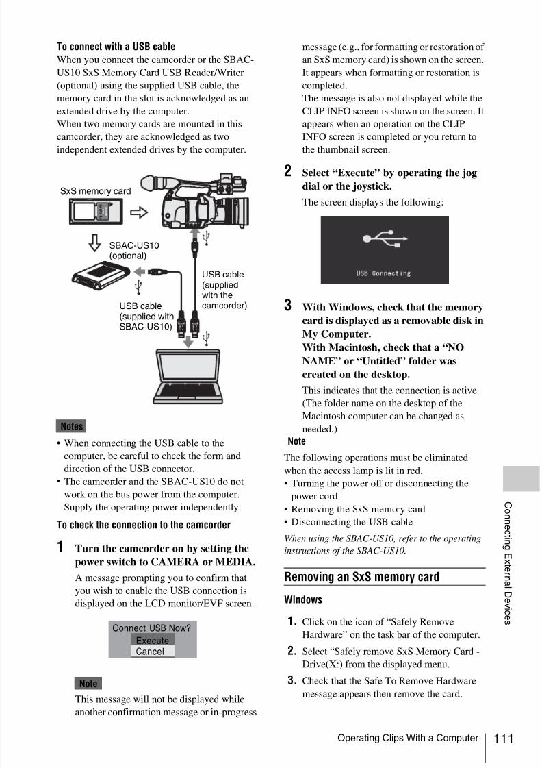
8/13/2019 Uputstvo Za Ex1
http://slidepdf.com/reader/full/uputstvo-za-ex1 111/132
Operating Clips With a Computer 111
C onn e c t i n gE x t er n al D ev i c e s
To connect with a USB cable
When you connect the camcorder or the SBAC-
US10 SxS Memory Card USB Reader/Writer
(optional) using the supplied USB cable, the
memory card in the slot is acknowledged as an
extended drive by the computer.
When two memory cards are mounted in this
camcorder, they are acknowledged as twoindependent extended drives by the computer.
Notes
• When connecting the USB cable to the
computer, be careful to check the form and
direction of the USB connector.
• The camcorder and the SBAC-US10 do not
work on the bus power from the computer.
Supply the operating power independently.
To check the connection to the camcorder
1 Turn the camcorder on by setting the
power switch to CAMERA or MEDIA.
A message prompting you to confirm that
you wish to enable the USB connection is
displayed on the LCD monitor/EVF screen.
This message will not be displayed while
another confirmation message or in-progress
message (e.g., for formatting or restoration of
an SxS memory card) is shown on the screen.
It appears when formatting or restoration is
completed.
The message is also not displayed while the
CLIP INFO screen is shown on the screen. It
appears when an operation on the CLIP
INFO screen is completed or you return tothe thumbnail screen.
2 Select “Execute” by operating the jog
dial or the joystick.
The screen displays the following:
3 With Windows, check that the memory
card is displayed as a removable disk in
My Computer.
With Macintosh, check that a “NO
NAME” or “Untitled” folder was
created on the desktop.
This indicates that the connection is active.
(The folder name on the desktop of theMacintosh computer can be changed as
needed.)
Note
The following operations must be eliminated
when the access lamp is lit in red.
• Turning the power off or disconnecting the
power cord
• Removing the SxS memory card
• Disconnecting the USB cable
When using the SBAC-US10, refer to the operatinginstructions of the SBAC-US10.
Removing an SxS memory card
Windows
1. Click on the icon of “Safely Remove
Hardware” on the task bar of the computer.
2. Select “Safely remove SxS Memory Card -
Drive(X:) from the displayed menu.
3. Check that the Safe To Remove Hardware
message appears then remove the card.Note
S x S
P R O 8 G B
USB cable(supplied withSBAC-US10)
SBAC-US10(optional)
USB cable(suppliedwith thecamcorder)
SxS memory card
Connect USB Now?
Execute
Cancel

8/13/2019 Uputstvo Za Ex1
http://slidepdf.com/reader/full/uputstvo-za-ex1 112/132
Operating Clips With a Computer112
C onn e c t i n gE x t er n al D ev i c e s
Macintosh
Drag the SxS memory card icon on the desktop to
Trash.
If the SxS memory card icon is located on Finder,
click on the eject icon on its side.
Note
Do not select “Card Power Off” from the SxSmemory card icon displayed on the menu bar.
Using the XDCAM EX Clip BrowsingSoftware
To copy clips to the local disk of a computer, the
XDCAM EX Clip Browsing Software must be
used.
Install the XDCAM EX Clip Browsing Software
on the supplied CD-ROM to your computer.
Although the data regarding recorded materialsare stored over multiple files and folders, you can
easily handle the clips without considering such
data and directory structure by using the XDCAM
EX Clip Browsing Software.
Note
If you operate, e.g. copy the clips on the SxS
memory card by using the Explorer (Windows) or
Finder (Macintosh), the subsidiary data contained
by the clips may not be maintained. To avoid such
a problem, use the XDCAM EX Clip Browsing
Software.
See page 12 for the operating requirements, and
refer to the User’s Guide contained in the CD-ROM.
For support information on the XDCAM EX Clip
Browsing Software, visit the web sites shown in
“XDCAM EX web sites” on page 11 or on the cover
page of the supplied CD-ROM.
Using a nonlinear editing system
For a nonlinear editing system, optional editing
software that corresponds to the recording
formats used with this camcorder is required.
Store the clips to be edited on the HDD of your
computer in advance, using the supplied
XDCAM EX Clip Browsing Software.
Some editing software may not operate properly.
Be sure to confirm before use that it conforms to
the recording formats used with this camcorder.
To use Final Cut Pro of Apple Computer, Inc.It is necessary to convert the clips to files that can
be edited with the Final Cut Pro, using XDCAM
Transfer.
For information on XDCAM Transfer, visit the web
sites shown in “XDCAM EX web sites” on page 11
or on the cover page of the supplied CD-ROM.

8/13/2019 Uputstvo Za Ex1
http://slidepdf.com/reader/full/uputstvo-za-ex1 113/132
Connecting an External Device (i.LINK Connection) 113
C onn e c t i n gE x t er n al D ev i c e s
When an HDV-compatible video format (SP
1080/60i, SP 1080/50i, or SP 1080/24P) is
selected, you can record the same images as those
recorded on the memory card in this camcorder
on an external device connected to the
i.LINK(HDV) connector, or record the playback
picture of the external device on the memory card
in the camcorder.
Nonlinear editing conforming to the HDV format
is also enabled.
Notes
• When you set “i.LINK I/O” of the OTHERS
menu to “Enable,” no signal is output from the
SDI OUT connector.
• When a cable is connected to the i.LINK(HDV)
connector during playback, the display returns
to the thumbnail screen.
• Use the i.LINK(HDV) connector only for one-
to-one i.LINK connection.
When you set the camcorder to Camera mode, the
picture being shot with this camcorder is output as
an HDV stream via the i.LINK(HDV) connector.
It can be recorded on a connected HDV recorder
in synchronization with the REC START/STOP
operation on this camcorder.
1 Perform the preparatory settings of the
camcorder.
• Set the video format to SP 1080/60i, SP
1080/50i, or SP 1080/24P.
• Set “i.LINK I/O” (page 107) of the
OTHERS menu to “Enable.”
• Set “Trigger Mode” (page 108) of the
OTHERS menu to “Both” or “External.”
Both: To record both on the memory card
in the camcorder and on the external deviceExternal: To record only on the external
device
2 Set the external device to recording
standby status.
For operations of the external device, refer to
the operation manual of that device.
3 Set the camcorder to Camera mode by
setting the power switch to CAMERA.
4 Press the REC START/STOP button.
The external device starts recording in
synchronization.
The status of the external device is displayed in
the i.LINK status indication area (page 18) on the
LCD monitor/EVF screen.
Notes
• Operation may be different depending on the
type of external device.
• Although there is some time lag from which you
press the REC START/STOP button until the
i.LINK status indication changes, the same
pictures are recorded on the memory card in this
camcorder and the external device if “Trigger
Mode” is set to “Both.”
• While you can record shot marks on the
memory card during recording, they are not
added to the pictures recorded on the external
device.
You can transfer an HDV stream to a nonlinear
editing system connected via the i.LINK(HDV)
connector.
Notes
• The i.LINK(HDV) connector of this camcorder
is a 4-pin connector. Check the number of pins
of the i.LINK connector on your computer and
use an appropriate i.LINK cable.
• In searching pictures of this camcorder on the
computer, it may take some time until the
display is reflected on the computer.
• If the playback clip is short or the playbackstarting point is near the end of the clip, the
i.LINK signal may be interrupted between the
clip and the next clip. When you try to capture
Connecting an ExternalDevice (i.LINKConnection)
Recording the Camcorder Pictureon an External Device
Indication Status of the external device
STBY In HDV recording standby
zREC In HDV recording
Nonlinear Editing
HDV
HDV

8/13/2019 Uputstvo Za Ex1
http://slidepdf.com/reader/full/uputstvo-za-ex1 114/132
Connecting an External Device (i.LINK Connection)114
C onn e c t i n gE x t er n al D ev i c e s
such a signal using the nonlinear editing system,
a malfunction may occur, depending on the
nonlinear editing software in use.
• If you specify a search speed other than 4 or 15
times normal with the nonlinear editing system,
no i.LINK signal is fed out. In such a case, the
picture on the LCD monitor may stay frozen.
• High-speed playback picture may not bedisplayed on the computer screen, depending on
the nonlinear editing software in use.
Setting on this camcorder
Set “i.LINK I/O” of the OTHERS menu to
“Enable.”
For operations of the nonlinear editing software,
refer to the operation manual of the software.
The HDV stream input from a device connected
via the i.LINK connector can be recorded on an
SxS memory card in this camcorder.
The timecodes superimposed on the i.LINK input
are recorded regardless of the settings of the
camcorder.
1 Set the external signal to a format that
can be recorded on the camcorder.
Signals of 1440 × 1080/59.94i can be
recorded when “Video Format” (page 108) is
set to SP 1080/60i or SP1080/24P. Signals of
1440 × 1080/50i can be recorded when set to
SP 1080/50i.
Recording is not allowed with other
combinations of “Video Format” and input
signals.
2 Set “i.LINK I/O” (page 107) of the
OTHERS menu to “Enable.”
3 Set the camcorder to Media mode.
4 Press the STOP button to set the
camcorder to STOP mode.
The input image is displayed on the LCD
monitor/EVF screen and the monitor
connected via the COMPONENT OUT
connector or A/V OUT connector.
The audio signal is output from the built-in
speaker (or headphones connected to the
headphone jack) and the speaker of the
monitor connected to the A/V OUT
connector.
5 Press the REC START/STOP button on
the handle.
Recording begins.
Notes• The REC START/STOP button on the grip does
not function.
• An error is generated in the following cases. In
such a case, cancel Recording mode by pressing
the REC START/STOP button.
—The video format of input signal does not
match that specified on the camcorder.
—A copy-protected stream is being fed in.
• If the input to the camcorder becomes no signal
during recording, the tally lamps and the
i.LINK zREC status indication on the LCD
monitor/EVF screen flash, indicating that no
signal is being recorded on the SxS memory
card.
When an input signal is resumed, recording is
restarted, incrementing the clip number on the
memory card.
Recording External Input Signals

8/13/2019 Uputstvo Za Ex1
http://slidepdf.com/reader/full/uputstvo-za-ex1 115/132
Important Notes on Operation 115
A p p en d i x e s
Use and Storage
Do not subject the unit to severe shocks
The internal mechanism may be damaged or the
body warped.
Do not cover the unit while operating
Putting a cloth, for example, over the unit can
cause excessive internal heat build-up.
After use
Always set the power switch to OFF.
Before storing the unit for a long period
Remove the battery pack.
Shipping
• Remove the memory cards before transporting
the unit.
• If sending the unit by truck, ship, air or other
transportation service, pack it in the shipping
carton of the unit.
Care of the unit
Remove dust and dirt from the surfaces of the lens
using a blower.
If the body of the unit is dirty, clean it with a soft,
dry cloth. In extreme cases, use a cloth steeped in
a little neutral detergent, then wipe dry. Do not
use organic solvents such as alcohol or thinner, as
these may cause discoloration or other damage to
the finish of the unit.
To remove dust from inside the viewfinder
remove the viewfinder by sliding it while holding
the viewfinder release lever downward.
In the event of operating problems
If you should experience problems with the unit,
contact your Sony dealer.
Use and storage locations
Store in a level, ventilated place. Avoid using or
storing the unit in the following places:
• In excessive heat or cold (operating temperature
range: 0ºC to 40ºC or 32ºF to 104ºF)
Remember that in summer in warm climates the
temperature inside a car with the windows
closed can easily exceed 50ºC (122ºF).
• In damp or dusty locations
• Locations where the unit may be exposed to rain
• Locations subject to violent vibration
• Near strong magnetic fields
• Close to radio or TV transmitters producing
strong electromagnetic fields.
• In direct sunlight or close to heaters for
extended periods
To prevent electromagnetic interference from
portable communications devices
The use of portable telephones and other
communications devices near this unit can result
in malfunctions and interference with audio and
video signals.
It is recommended that the portable
communications devices near this unit be
powered off.
About the LCD panels
The LCD panels are manufactured with
extremely high-precision technology that yields
effective pixel rates of 99.99% or higher.
However, very rarely, one or more
pixels may be permanently dark or permanently
lit in white, red, blue, or green.
This phenomenon is not a malfunction. Such
pixels have no effect on the recorded data, and the
unit may be used with confidence even if they are
present.
Appendixes
Important Notes on Operation
H L O F F
A
Viewfinder releaselever
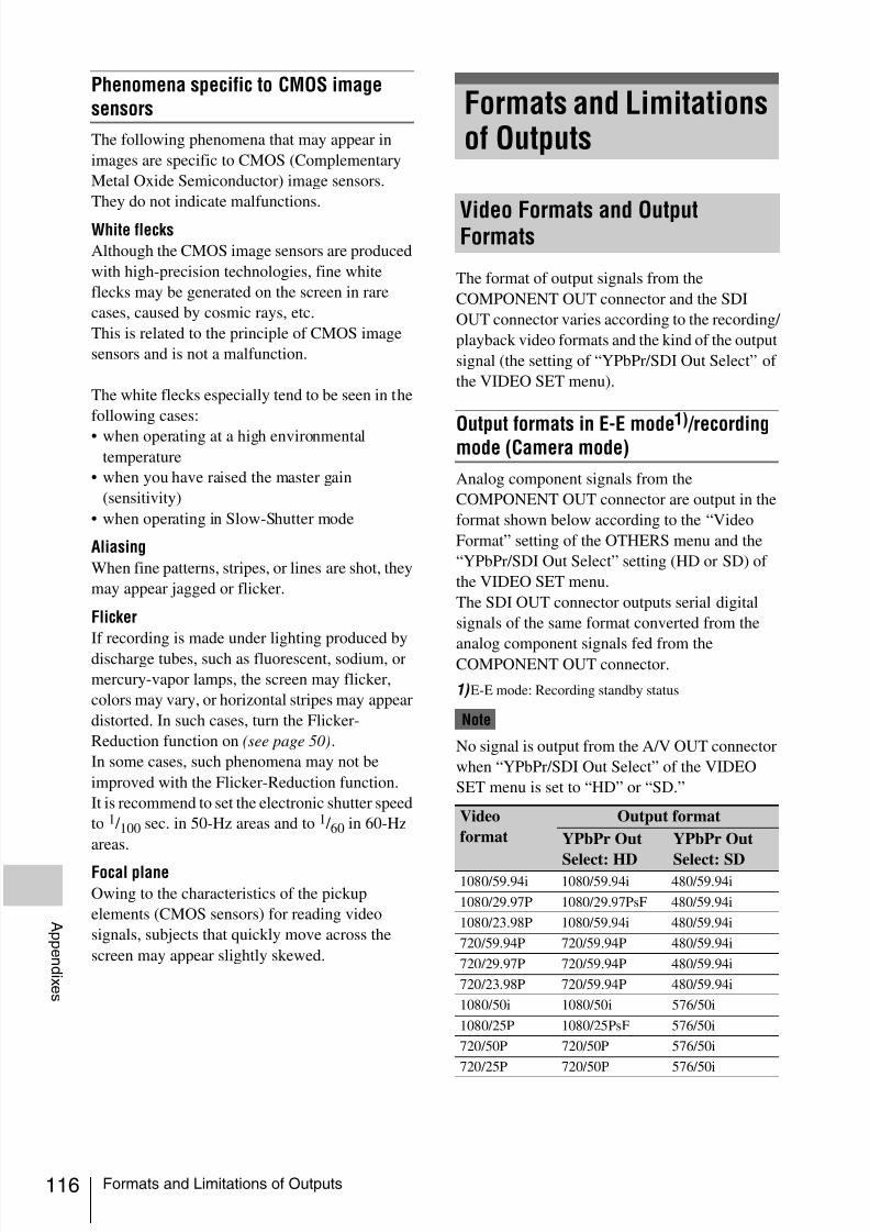
8/13/2019 Uputstvo Za Ex1
http://slidepdf.com/reader/full/uputstvo-za-ex1 116/132
Formats and Limitations of Outputs116
A p p en d i x e s
Phenomena specific to CMOS imagesensors
The following phenomena that may appear in
images are specific to CMOS (Complementary
Metal Oxide Semiconductor) image sensors.
They do not indicate malfunctions.
White flecks
Although the CMOS image sensors are produced
with high-precision technologies, fine white
flecks may be generated on the screen in rare
cases, caused by cosmic rays, etc.
This is related to the principle of CMOS image
sensors and is not a malfunction.
The white flecks especially tend to be seen in the
following cases:
• when operating at a high environmental
temperature
• when you have raised the master gain
(sensitivity)
• when operating in Slow-Shutter mode
Aliasing
When fine patterns, stripes, or lines are shot, they
may appear jagged or flicker.
Flicker
If recording is made under lighting produced by
discharge tubes, such as fluorescent, sodium, or
mercury-vapor lamps, the screen may flicker,
colors may vary, or horizontal stripes may appear
distorted. In such cases, turn the Flicker-
Reduction function on (see page 50).
In some cases, such phenomena may not be
improved with the Flicker-Reduction function.
It is recommend to set the electronic shutter speed
to 1 / 100 sec. in 50-Hz areas and to 1 / 60 in 60-Hz
areas.
Focal plane
Owing to the characteristics of the pickup
elements (CMOS sensors) for reading video
signals, subjects that quickly move across the
screen may appear slightly skewed.
The format of output signals from the
COMPONENT OUT connector and the SDI
OUT connector varies according to the recording/
playback video formats and the kind of the output
signal (the setting of “YPbPr/SDI Out Select” of
the VIDEO SET menu).
Output formats in E-E mode1)
/recordingmode (Camera mode)
Analog component signals from the
COMPONENT OUT connector are output in the
format shown below according to the “Video
Format” setting of the OTHERS menu and the
“YPbPr/SDI Out Select” setting (HD or SD) of
the VIDEO SET menu.
The SDI OUT connector outputs serial digital
signals of the same format converted from the
analog component signals fed from theCOMPONENT OUT connector.
1) E-E mode: Recording standby status
Note
No signal is output from the A/V OUT connector
when “YPbPr/SDI Out Select” of the VIDEO
SET menu is set to “HD” or “SD.”
Formats and Limitationsof Outputs
Video Formats and OutputFormats
Video
format
Output format
YPbPr Out
Select: HD
YPbPr Out
Select: SD1080/59.94i 1080/59.94i 480/59.94i
1080/29.97P 1080/29.97PsF 480/59.94i
1080/23.98P 1080/59.94i 480/59.94i
720/59.94P 720/59.94P 480/59.94i
720/29.97P 720/59.94P 480/59.94i
720/23.98P 720/59.94P 480/59.94i
1080/50i 1080/50i 576/50i
1080/25P 1080/25PsF 576/50i
720/50P 720/50P 576/50i
720/25P 720/50P 576/50i

8/13/2019 Uputstvo Za Ex1
http://slidepdf.com/reader/full/uputstvo-za-ex1 117/132
Formats and Limitations of Outputs 117
A p p en d i x e s
Output formats in clip playback mode(Media mode)
Analog component signals from the
COMPONENT OUT connector are output in the
format shown below according to the video
format of the playback clip and the “YPbPr/SDI
Out Select” setting (HD or SD) of the VIDEO
SET menu.
The SDI OUT connector outputs serial digital
signals of the same format converted from the
analog component signals fed from the
COMPONENT OUT connector.
Note
No signal is output from the A/V OUT connector
when “YPbPr/SDI Out Select” of the VIDEO
SET menu is set to “HD” or “SD.”When the frame rate setting of the video format
is 59.94i/59.94P/29.97P/23.98P
1) No signal is fed from the SDI OUT connector.
2) The actual frame rate of the output signal is 1.001
times of the value shown in the table. Some frame may
be repeated when converting the frame rate.
When the frame rate setting of the video format
is 50i/50P/25P
1) No signal is fed from the SDI OUT connector.
2) The actual frame rate of the output signal is 1/1.001 of
the value shown in the table. Some frame may be
deleted when converting the frame rate.
The outputs from the camcorder are limited by the VIDEO SET menu settings as follows. These
limitations are common to Camera mode and Media mode.
Clip format Output format
YPbPr Out
Select: HD
YPbPr Out
Select: SD
1080/59.94i 1080/59.94i 480/59.94i
1080/29.97P 1080/29.97PsF 480/59.94i
1080/23.98P 1080/59.94i 480/59.94i
720/59.94P 720/59.94P 480/59.94i
720/29.97P 720/59.94P 480/59.94i
720/23.98P 720/59.94P 480/59.94i
1080/50i 1080/59.94i1), 2) 480/59.94i1)
1080/25P 1080/29.97PsF1), 2) 480/59.94i1)
720/50P 720/59.94P1), 2) 480/59.94i1)
720/25P 720/59.94P1), 2) 480/59.94i1)
Clip format Output format
YPbPr Out
Select: HD
YPbPr Out
Select: SD
1080/59.94i 1080/50i1), 2) 576/50i1)
1080/29.97P 1080/25PsF1), 2)
576/50i1)
1080/23.98P 1080/50i1), 2) 576/50i1)
720/59.94P 720/50P1), 2) 576/50i1)
720/29.97P 720/50P1), 2) 576/50i1)
720/23.98P 720/50P1), 2) 576/50i1)
1080/50i 1080/50i 576/50i
1080/25P 1080/25PsF 576/50i
720/50P 720/50P 576/50i
720/25P 720/50P 576/50i
Limitations of Outputs
Menu settings i.LINK I/O Enable Disable Enable Disable Enable Disable
YPbPr/SDI Out Select HD HD SD SD Off Off
Outputs from
the output
connectors
i.LINK(HDV) HDV No signal HDV No signal HDV No signal
SDI OUT No signal HD No signal SD No signal No signal
COMPONENT OUT HD HD SD SD No signal No signalA/V OUT No signal No signal No signal No signal SD SD

8/13/2019 Uputstvo Za Ex1
http://slidepdf.com/reader/full/uputstvo-za-ex1 118/132
Backup Battery118
A p p en d i x e s
This camcorder uses a backup battery to retain
various setting data.A lithium battery (CR2032) for backup is
mounted in the camcorder at the factory.
The backup battery retains the date, time, and
timecode in Free Run mode even when no
operating power is being supplied.
Service life of the backup battery
When the backup battery’s voltage falls, the
backup battery low-voltage warning appears on
the LCD monitor/viewfinder screen.If this warning appears, replace the battery as
soon as possible.
Battery may explode if mistreated.
Do not recharge, disassemble, or dispose of in
fire.
• Danger of explosion if battery is incorrectlyreplaced. Replace only with the same or
equivalent type recommended by the
manufacturer.
• Dispose of used batteries according to the
manufacturer’s instructions.
Replacing the backup battery
Notes
• Be sure to set the power switch to OFF whenreplacing the backup battery.
• Be careful not to drop the removed screw into
the camcorder.
1 Open the cover of the backup battery
holder on the bottom by loosening the
screw, and remove the battery.
2 Insert a new backup battery (CR2032)
with the + symbol on the battery facing
outside.
3 Attach the cover in the original position.
Backup Battery
WARNING
CAUTION
CR2025
3V
CR2025
3V
CR2025
3V

8/13/2019 Uputstvo Za Ex1
http://slidepdf.com/reader/full/uputstvo-za-ex1 119/132
Troubleshooting 119
A p p en d i x e s
Troubleshooting
Operating Power
Symptoms Cause Remedy
The camcorder does not
power on when you set
the power switch either to
CAMERA or MEDIA.
No battery pack is mounted and no
power is supplied to the DC IN
connector.
Mount a battery pack (page 21) or connect an AC
power using the BC-U1(page 22) .
The battery pack is completely
exhausted.
Replace the battery pack with a fully charged one
(page 21).
The power supply cuts
while operating.
The battery pack becomes exhausted. Replace the battery pack with a fully charged one
(page 21).
The battery pack becomes
exhausted very quickly.
The ambient temperature is very low. This owes to the battery characteristics and is not a
defect.
The battery pack is inadequately
charged.
Recharge the battery pack (page 21).
If the battery pack is soon exhausted even after you
charged it fully, it may comes to the end of its life.
Replace it with a new one.
Recording/Playback
Symptoms Cause Remedy
Recording does not start
when you press the REC
START/STOP button.
The power switch is set to OFF or
MEDIA.
Set the power switch to CAMERA.
The SxS memory card is write-
protected.
Release the write protection (page 29), or replace the
card with a non-protected SxS memory card.
The SxS memory card is full. Replace the card with one having sufficient space.
The SxS memory card needs
restoration.
Restore the memory card (page 32).
Playback does not start
when you press the PLAY
button.
The power switch is set to OFF or
CAMERA.
Set the power switch to MEDIA.
The supplied IR Remote
Commander does not
work.
Remote control operation is disabled. Enable remote control operation (page 27).
The battery of the IR Remote
Commander is exhausted.
Replace the battery with a new one.
Audio recording is not
possible.
The AUDIO LEVEL (CH-1/CH-2)
controls are set to the minimum level.
Adjust the audio recording levels with the AUDIO
LEVEL (CH-1/CH-2) controls (page 54).
The recorded sound is
distorted.
The audio level is too high. Adjust the audio recording levels with the AUDIO
LEVEL (CH-1/CH-2) controls (page 54), and record
again.
The recorded sound has a
high noise level.
The audio level is too low. Adjust the audio recording levels with the AUDIO
LEVEL (CH-1/CH-2) controls (page 54), and recordagain.

8/13/2019 Uputstvo Za Ex1
http://slidepdf.com/reader/full/uputstvo-za-ex1 120/132
Troubleshooting120
A p p en d i x e s
External Devices
Symptoms Cause Remedy
The equipment connected
to the camcorder via an
i.LINK connection doesnot react as expected, for
example, no picture
appears on its screen.
It sometimes takes time for the
connected equipment to recognize
the operation.
Wait for about 15 seconds. If the connected
equipment still does not react, do the following:
• Check the i.LINK cable, for example, by re-plugging it.
• Turn the power off, and connect the cable again.
• Change the i.LINK cable.

8/13/2019 Uputstvo Za Ex1
http://slidepdf.com/reader/full/uputstvo-za-ex1 121/132
Error/Warning Indications 121
A p p en d i x e s
The camcorder informs you of situations where
warning, caution, or an operation check isrequired, through messages on the LCD monitor/
EVF screen, the tally lamps, and a buzzer.
The buzzer is output to the built-in speaker or to
the headphones connected via the headphoneconnector. The buzzer volume can be adjusted
with “Alarm Level” in “Audio Output” of the
AUDIO SET menu.
The camcorder stops operation after the following indications.
When one of the following indications is generated, follow the message to clear the problem.
Error/Warning Indications
Error Indications
Error indication on
LCD/EVF
Buzzer Tally
lamps
Cause and measures
E + Error code Continuous Rapidly
flashing
The camcorder may be defective.
Turn off the power and consult Sony service personnel.
(If power cannot be turned off by setting the power switch to
OFF, remove both the battery pack and the DC IN source.)
Warning Indications
Warning indication
on LCD/EVF
Buzzer Tally
lamps
Cause and measures
Media Near Full Intermittent Flashing Free space on the SxS memory card has become insufficient.
Replace it with another at the earliest opportunity.
Media Full Continuous Rapidly
flashing
No space is left on the SxS memory card. Recording, clip
copying and clip division cannot be performed.
Replace it with another.
Battery Near End Intermittent Flashing The battery power will be exhausted soon.
Charge the battery pack at the earliest opportunity.
Battery End Continuous Rapidly
flashing
The battery pack is exhausted. Recording cannot be
performed.
Connect a power source via the DC IN connector or stop
operation to charge the battery pack.
Temperature High Intermittent Flashing The internal temperature has risen above a safe operation
limit.
Suspend operation, turn off the power, and wait until the
temperature falls.
Voltage Low Intermittent Flashing The DC IN voltage has become low (stage 1).
Check the power supply.
Insufficient Voltage Continuous Rapidly
flashing
The DC IN voltage is too low (stage 2). Recording cannot be
performed.
Connect other power source.
Battery Error
Please Change Battery.
An error was detected with the battery pack.
Replace the battery pack with a normal one.
Backup Battery End
Please Change.
The remaining power of the backup battery is insufficient.
Replace the battery with a new one.

8/13/2019 Uputstvo Za Ex1
http://slidepdf.com/reader/full/uputstvo-za-ex1 122/132

8/13/2019 Uputstvo Za Ex1
http://slidepdf.com/reader/full/uputstvo-za-ex1 123/132
About i.LINK 123
A p p en d i x e s
This section explains the specifications and
features of i.LINK.
What is i.LINK?
i.LINK is a digital serial interface designed to
integrate devices equipped with i.LINK
connectors. i.LINK allows your device to:
• Perform two-way transmission and reception of
data such as digital audio and digital video
signals.
• Control other i.LINK devices.
• Easily connect multiple devices with a singlei.LINK cable.
Your i.LINK device is capable of connecting to a
wide range of digital AV devices for data transfer
and other operations.
Other advantages include the following feature.
When connected to multiple i.LINK devices,
your i.LINK device can perform data transfer and
other operations not only
with the directly connected devices but also with
any of the devices that are connected to thosedevices. Therefore, you do not need to be
concerned with device connection order.
However, depending on the features and
specifications of the connected devices, you may
need to use certain functions differently, and you
may not be able to transfer data or perform certain
operations.
i.LINK, a nickname for IEEE 1394 proposed by
Sony, is a trademark supported by many
companies worldwide.IEEE 1394 is an international standard defined by
IEEE, the Institute of Electrical and Electronics
Engineers, Inc.
Note
The camcorder can be connected to one device
with the i.LINK cable (DV cable). When you
connect with a device that has two or more
i.LINK connectors, refer to the
operating instructions supplied with the
connected device.
About data transfer speed of i.LINK
i.LINK defines a maximum data transfer speed of
approximately 100, 200 and 400 Mbps1) that are
described as S100, S200 and S400 respectively.
For i.LINK devices, a maximum data transfer
speed that the device supports is identified on
“Specifications” page of the operatinginstructions supplied with the device or near its
i.LINK connector.
1) When connecting with the device that support
different data transfer speed, the actual data transfer
speed may be different from those described on the
i.LINK connectors.
What is Mbps?
Mega bits per second. A measure of the rate at
which data is transmitted per second. In case of
100 Mbps, 100 Mega bits of data can betransmitted per second.
i.LINK operation with your camcorder
For details on operation when other equipment
with i.LINK (HDV) connector is connected, see
page 113.
For details on connection with i.LINK cable and
necessary software, refer to the operating
instructions supplied with the connected device.
About the required i.LINK cable
Use the Sony 6-pin-to-4-pin or 4-pin-to-4-pin
i.LINK cable (for HDV dubbing) to connect the
i.LINK devices.
i.LINK and are trademarks.
About i.LINK

8/13/2019 Uputstvo Za Ex1
http://slidepdf.com/reader/full/uputstvo-za-ex1 124/132
Specifications124
A p p en d i x e s
Power requirements
DC 12 V
Power consumption
Approx. 12 W (Typical) (Recording,
EVF On, LCD monitor Off)
Peak inrush current
(1) Power ON, current probe method:
15 A (240V)(2) Hot switching inrush current,
measured in accordance with
European standard EN55103-1:
62 A (230V)
Operating temperature
0ºC to +40ºC (32ºF to 104ºF)
Storage temperature
–20ºC to +60ºC (–4ºF to 140ºF)
Recording/playback formats
Video
HQ mode: MPEG-2 MP@HL,
35 Mbps / VBR
1920 × 1080/59.94i, 50i, 29.97P, 25P,
23.98P
1280 × 720/59.94P, 50P, 29.97P, 25P,
23.98P
SP mode: MPEG-2 MP@H-14,
25 Mbps /CBR1440 × 1080 /59.94i, 50i
(23.98P is converted to 59.94i in 2-3
pull-down processing.)
Audio
LPCM (16 bits, 48 kHz, 2 channels)
Recording/playback time
With one SBP-8
SP mode: Approx. 35 min.
HQ mode: Approx. 25 min.
With one SBP-16
SP mode: Approx. 70 min.
HQ mode: Approx. 50 min.
Continuous operation time
(Recording, EVF On, LCD monitor Off)
With the BP-U60
Approx. 4 hours
With the BP-U30
Approx. 2 hours
Mass
Camcorder: 2.4 kg (5 lb 5 oz)
With the supplied lens hood, eyecup,
BP-U30 battery pack and one SxS
memory card: 2.8 kg (6 lb 3 oz)
Dimensions
See page 126 .
Supplied accessoriesSee page 8.
Lens
Focal length
5.8 mm to 81.2 mm
(equivalent to 31.4 mm to 439 mm on35 mm lens)
Zoom
Servo/Manual selectable
Zoom ratio
14×
Maximum relative aperture
1:1.9
IrisAuto/Manual selectable
F1.9 to F16 and C (close)
Focus
Auto/Manual selectable
Ranges:
800 mm to ∞ (Macro OFF)
50 mm to ∞ (Macro ON, Wide)
735 mm to ∞ (Macro ON, Tele)
Picture stabilizing functionSteadyShot ON/OFF possible, shift-lens
system
Specifications
General
Camera Block

8/13/2019 Uputstvo Za Ex1
http://slidepdf.com/reader/full/uputstvo-za-ex1 125/132
Specifications 125
A p p en d i x e s
Filter thread
M77 mm, pitch 0.75 mm
Micro
ON/OFF switchable
Camera
Pickup device1 / 2-inch type, CMOS image sensor
Effective picture elements:
1920 (H) × 1080 (V)
Format
3-chip RGB
Optical system
F1.6 prism system
Built-in filters
ND filters
OFF: Clear
1: 1 / 8ND
2: 1 / 64ND
Sensitivity
F10 (Typical) (With 1080/60i, 89.9%
reflection, 2000 lx)
Minimum illumination
0.14 lx (F1.9, +18 dB, 64-frame
accumulation)
Video S/N
54 dB (Y) (Typical)
Horizontal resolution
1000TV lines or more (with HQ 1080,
HD SDI output)
Gain
–3, 0, 3, 6, 9, 12, 18 dB, AGC
Shutter speed1 / 32 to 1 / 2000 sec.
Slow shutter
2 to 8 frames
EX Slow Shutter: 16, 32, 64 frames
Built-in microphones
Stereo electret condenser microphones
Directivity: Omnidirectional
Built-in speaker
Monaural
Output: 250 mW
LCD monitor
Screen size
8.8 cm diagonal (3.5-inch)
Aspect ratio
16:9
Picture size
640 (H) × 3 (RGB) × 480 (V) delta
sequence
Transmission
Hybrid (semi-transmissive) type
Viewfinder
Screen size
1.4 cm diagonal (0.54-inch)
Aspect ratio
16:9
Picture elements
1120 (H) × 225 (V)
Input connectors
AUDIO IN CH1/CH2 connectors
XLR 3-pin (2), female
LINE: +4 dBu
MIC: –8 dBu to –65 dBu (3-dB steps)
(Reference level: 0 dBu=0.775 Vrms)
DC IN connector
DC jack (1)
Output connectors
A/V OUT connector
AV multiconnector (1)Audio: –10 dBu (47k Ω load, reference
level)
Audio Block
Displays
Inputs/Outputs

8/13/2019 Uputstvo Za Ex1
http://slidepdf.com/reader/full/uputstvo-za-ex1 126/132
Specifications126
A p p en d i x e s
Analog composite/YC signals: NTSC or
PAL
COMPONENT OUT connector
Mini D connector (1)
Y: 1.0 Vp-p, 75Ω
Pb / Pr: 0.7 Vp-p, 75Ω
Headphone connector
Stereo mini jack (1), –20.5 dBu
(reference level output, 16Ω load)
SDI OUT connector
BNC type (1), conforming to
SMPTE292M/259M standards
Computer connectors
i.LINK (HDV) connectori.LINK, IEEE1394, 4-pin connector (1),
S400
USB connector
mini-B/USB2.0 Hi-Speed (1)
Battery pack
BP-U30, BP-U60Battery charger
BC-U1
CSxS memory card
SxS PRO SBP-8 (8 GB), SBP-16 (16 GB)
SxS memory card USB reader/writer
SBAC-US10
Electret condenser microphone
ECM-673
Wide conversion lens
VCL-EX0877
Design and specifications are subject to change
without notice.
Dimensions
Optional Accessories
OPEN
CLOSE
OPEN
CLOSE
AF /M F F ul lM F
1 5
2 5
4 0
8 1 . 2
1 0
3
1 0
m m
5
1 0
3 0
f t
1 5
5 . 8
C
MANU AUTO
MANU AUTO
MACRO
FOCUS
PUSHAF
IRIS
OFF ON
8
5 . 6
4
2 . 8
1 . 9
1 6
1 2 3
ASSIGN
LENS INFO BRT DISP HISTOGRAM
AUTO
MANUAL
INT
EXT
PICTUREPROFILE
PMW-EX1
DCIN
CH-2
AUTO
MANUAL
INT
EXTCH-1
AUDIOSELECT
AUDIOIN
OFFCAMERACANCELSEL/SET M EDIA
BATTERYRELEASE
ZEBRA PEAKING
GAINOFF
2
1
NDFILTER
BA
PRST
LMH
WHITEBAL
FULL AUTO
SLOTSELECT
MENU
CH-1
AUDIOLEVEL
CH-2
MENU
CH-1
AUDIOLEVEL
CH-2
A B
OPEN
ACCESS
1 3 6 . 5
( 5 3 / 5 )
1 1 6 ( 4 5 / 8 )
7 3 . 1
( 3 )
6 0
( 2 3 / 8 )
380.8 (13 1 / 8)
264.6 (10 1 / 2)
40.2(1 5 / 8)
6.6 (9 / 32) 178 (7 1 / 8)
Unit: mm (inches)

8/13/2019 Uputstvo Za Ex1
http://slidepdf.com/reader/full/uputstvo-za-ex1 127/132

8/13/2019 Uputstvo Za Ex1
http://slidepdf.com/reader/full/uputstvo-za-ex1 128/132
Index128
A p p en d i x e s
AA/V OUT connector 110AC adaptor 22AC power source 22ACCESS lamps 30Accessory shoe 14add shot marks 86AF mode 49AGC mode 41All Clips DEL 75
All Reset 76, 105Angle mode 42Area Detection 74Aspect Marker 39Aspect Select 39Assign Button 56, 106assignable buttons 56ATW 37, 57ATW Speed 100Audio 53AUDIO IN connectors 53AUDIO IN switches 53Audio Input 101AUDIO LEVEL controls 53audio monitoring 54Audio Output 101audio recording levels 54AUDIO SELECT switches 53AUDIO Status 90
Auto Focus 47Auto Iris mode 44Auto Shutter 43Auto Shutter mode 42Auto Tracing White 37Auto White Balance 38
BBacklight 57backlight (EVF) 26backlight (LCD) 25backup battery 118BARS/CAM button 55
Battery Alarm 107Battery INFO 107BATTERY INFO display 22Battery Pack 21BATTERY RELEASE button 21BATTERY/MEDIA Status 92
BC-U1 Battery Charger 21, 22Black 74Black Gamma 74BP-U30 21BP-U60 21BRT DISP 56BRT Disp 57built-in clock 23Built-in microphones 53Built-in speaker 80BUTTON/REMOTE Status 91Buzzer 121
CCamera Data 76, 105Camera mode 23CAMERA SET Menu 97CAMERA Status 89CANCEL button 82, 94
Card slots 30Center Marker 39Clip 35, 108CLIP INFO screen 83clip name 35Clip Operation menu 81, 82Clock mode 51Clock Set 106CMOS Image Sensors 116color bar 55Color Bar Type 98Color Correction 71COMPONENT OUT connector 109copy a clip 84COPY CLIP 84Country 108Cueing up 80
D
Date/Time 23DC IN connector 22DC IN Power 22
Index

8/13/2019 Uputstvo Za Ex1
http://slidepdf.com/reader/full/uputstvo-za-ex1 129/132
Index 129
A p p en d i x e s
delete a clip 84DELETE CLIP 84delete shot marks 86Detail 72DF 51diopter compensation 25
Direct Menu 107Direct menu 19, 37, 41, 44, 49, 50, 61,
70DISP CLIP INFO 83Display On/Off 104DISPLAY/BATT INFO button 18, 22divide a clip 87DIVIDE CLIP 87Down Converter 102
EECS 42EJECT buttons 30electronic shutter 42Electronic Viewfinder 25Entering a character string 96Error Indications 121EVF 25, 103EVF (menu) 26
EVF Mode 57EX Slow Shutter 42, 43, 97EXPAND CLIP 85EXPAND CLIP screen 84EXPAND FOCUS button 47Expanded Focus 57ExpressCard slot of a computer 110Extended Clear Scan 42external microphone 53external monitor 109eyecup 26Eyepiece focusing knob 26
FF FWD button 79F REV button 79Fade In 67, 68Fade Out 67, 68Fader 57, 67, 99
Fixed gain mode 41Fixed Shutter mode 42Flicker Reduce 50, 98
focus 47Focus ring 47Format Media 108Formatting 31Frame Rec 99Frame Recording 59
Free Run mode 51Freeze Mix 57, 62FULL AUTO button 33Full Auto mode 33Full Manual Focus 47Full MF mode 47
Ggain 41Gain Setup 41, 97GAIN switch 41Gamma 74Grip 27Guide Frame 39
HHeadphone connector 54, 80high-speed playback 79HISTOGRAM 56
Histogram 57Hooks for the shoulder strap 14Hours Meter 107
Ii.LINK 123i.LINK cable 123i.LINK I/O 107, 113i.LINK(HDV) connector 113
index frame 77, 87Interval Rec 99Interval Recording 57IR Remote 27, 57, 107IR Remote Commander 27iris 44iris opening 44Iris ring 44IRIS switch 44
JJog dial 16, 94Joystick 15, 94

8/13/2019 Uputstvo Za Ex1
http://slidepdf.com/reader/full/uputstvo-za-ex1 130/132
Index130
A p p en d i x e s
KKnee 73
LLanguage 106Last Clip DEL 57, 75LCD 25, 103LCD B.LIGHT + and – buttons 25LCD B.LIGHT switch 25LCD monitor 24LCD/VF SET Menu 103lens cap 33Lens hood 13LENS INFO 56Lens Info 57
LENS REMOTE connector 46LINE/MIC/+48V switches 53Low Key SAT 74
MMacro mode 49MACRO switch 49Manual Focus 47Manual Iris mode 44Manual Zoom mode 45Marker 39, 57, 103Matrix 71MEDIA 77Media mode 23MENU button 94Menu controls 94MF Assist 48, 98MF mode 48microphone holder 53
MONITOR VOL buttons 54, 80
NND filter switch 36ND filters 36NDF 51NEXT button 80
O
OK mark 83OK MARK ADD 83OK MARK DEL 84One-Push Auto Focusing 48
OTHERS Menu 105Output Formats 116
PPeaking 48, 103PEAKING button 48
PICTURE FROFILE menu 69, 71PICTURE PROFILE button 69Picture Profiles 69PLAY/PAUSE button 78Playback 78Power switch 23Power Zoom 45Power Zoom (Servo) mode 45Power zoom lever 46PREV button 80Profile Name 71PUSH AF button 48
RRange index 47Rec 57REC HOLD lever 34Rec Review 34, 56, 57, 99REC REVIEW button 34, 56
Rec Run mode 51REC START/STOP button 34Recall 76reference tone 55Regen mode 51RELEASE button 27restoration 32
S
S&Q Motion 60, 99Safety Area 39Safety Zone 39SBAC-US10 111SBP-16 29SBP-8 29SDI OUT connector 109SEL/SET button 94SEL/SET dial 94SET INDEX PIC 87
Setup 102setup file 76Setup menus 93

8/13/2019 Uputstvo Za Ex1
http://slidepdf.com/reader/full/uputstvo-za-ex1 131/132

8/13/2019 Uputstvo Za Ex1
http://slidepdf.com/reader/full/uputstvo-za-ex1 132/132