Upright Version Owner’s Manual - PLAY iT! …store.playitamusements.com/Manuals/Virtua Cop...
122
1ST PRINTING APRIL ‘03 MANUAL NO. 999-1776 SEGA AMUSEMENTS USA, INC. www.seuservice.com GAME CODE: VCT Owner’s Manual Upright Version
Transcript of Upright Version Owner’s Manual - PLAY iT! …store.playitamusements.com/Manuals/Virtua Cop...

1ST PRINTING APRIL ‘03
MANUAL NO. 999-1776
SEGA AMUSEMENTS USA, INC.
www.seuservice.com
GAME CODE: VCT
Owner’s ManualUpright Version

VISIT OUR WEBSITE!

BEFORE USING THE PRODUCT, BE SURE TO READ THE FOLLOWING:To maintain the safety:
To ensure the safe usage of the product, be sure to read the following before using the product. The following instructions are intended for the users, operators and the personnel in charge of the opera-tion of the product. After carefully reading and sufficiently understanding the warning displays and cautions, handle the product appropriately. Be sure to keep this manual nearby the product or else-where convenient for referring to it when necessary.
Herein, explanations which require special attention are enclosed with dual lines. Depending on the potentially hazardous degrees, the terms of WARNING, CAUTION, etc. are used. Be sure to under-stand the contents of the displays before reading the text.
Indicates that mishandling the prod-uct by disregarding this warning will cause a potentially hazardous situation which can result in death or serious injury.
Indicates that mishandling the product by disregarding this caution will cause a slight hazardous situation which can result in personal injury and or material damage.
For the safe usage of the product, the following pictographs are used:
Indicates “HANDLE WITH CARE.” In order to protect the human body an equipment, this display is attached to places where the Owner’s Manual and or Service Manual should be referred to.
Perform work in accordance with the instructions herein stated.Instructions for work are explained by paying attention to the aspect of accident prevention. Failing to perform work as per the instructions can cause accidents. In the case where only those who have tech-nical expertise should perform the work to avoid hazardous situation, the instructions herein state that the serviceman should perform such work.
Be sure to turn off power before working on the machine.To prevent electric shock, be sure to turn off power before starting the work in which the worker touches the interior of the product. If the work is to be performed in the power-on status, the Instruction Manual herein always states to that effect.
Be sure to ground the Earth Terminal (this, however, is not required in the case where a power cord with earth is used).This product is equipped with the Earth Terminal. When installing the product, Connect the Earth Ter-minal to the “accurately grounded indoor earth terminal” by using an earth wire. Unless the product is grounded appropriately, the user can be subject to electric shock. After performing repair, etc. for the Control equipment, ensure that the Earth Wire is firmly connected to the Control equipment.
Ensure that the Power Supply used is equipped with an Earth Leakage Breaker.This product does not incorporate the Earth Leakage Breaker. Using a power supply which is not equipped with the Earth Leakage Breaker can cause a fire when earth leakage occurs.
Be sure to use fuses which meet the specified rating. (only for the machines which use fuses).Using fuses exceeding the specified rating can cause a fire and electric shock.
WARNING! CAUTION!

Specification changes (removal of equipment, conversion and addition) not designated by SEGA are not allowed.The parts of the product include warning labels for safety, covers for personal protection, etc. It is very hazardous to operate the product by removing parts and or modifying the circuits. Should doors, lids and protective parts be damaged or lost, refrain from operating the product, and contact where the product was purchased from or the office herein stated. SEGA shall not be held responsible for any accidents, compensation for damage to a third party, resulting from the specifications not designated by SEGA.Ensure that the product meets the requirements of appropriate Electrical Specifications.Before installing the product, check for Electrical Specifications. SEGA products have a nameplate on which Electrical Specifications are described. Ensure that the product is compatible with the power supply voltage and frequency requirements of the location. Using any Electrical Specifications different from the designated Specifications can cause a fire and electric shock.Install and operate the product in places where appropriate lighting is available, allowing warning labels to be clearly read.To ensure safety for the customers, labels and printed instructions describing potentially hazardous situ-ation are applied to places where accidents can be caused. Ensure that where the product is operated has sufficient lighting allowing the warnings to be read. If any label is peeled off, apply it again imme-diately. Please place an order with where the product was purchased from or the office herein stated.When handling the Monitor, be very careful. (Applies only to the product w/monitor.)Some of the monitor (TV) parts are subject to high tension voltage. Even after running off power, some portions are still subject to high tension voltage sometimes. Monitor repair and replacement should be performed only be those technical personnel who have knowledge of electricity and technical expertise.Be sure to adjust the monitor (projector) properly. (Applies only to the product w/monitor.)Do not operate the product leaving on-screen flickering or blurring as it is. Using the product with the monitor not properly adjusted may cause dizziness or a headache to an operator, a player, or the cus-tomers.When transporting or reselling this product, be sure to attach this manual to the product.In the case where commercially available monitors and printers are used in this product, only the con-tents relating to this product are explained herein. Some commercially available equipment has func-tions and reactions not stated in this manual. Read this manual together with the specific Instruction Manual of such equipment.
Descriptions herein contained may be subject to improvement changes without notice.The contents described herein are fully prepared with due care. However, should any question arise or errors be found, please contact SEGA.
••
INSPECTIONS IMMEDIATELY AFTER TRANSPORTING THE PRODUCT TO THE LOCATION.
Normally, at the time of shipment, SEGA products are in a status allowing for usage immediately after transporting to the location. Nevertheless, an irregular situation may occur during transportation. Before turning on power, check the following points to ensure that the product has been transported in a satis-factory status.Are there any dented portions or defects (cuts, etc.) on the external surfaces of the cabinet?Are Casters and Adjusters, damaged?Do the power supply voltage and frequency requirements meet with those of the location?Are all wiring connectors correctly and securely connected? Unless connected in the correct direction, connector connections can not be made accurately. Do not insert connectors forcibly.Do power cords have cuts and dents?Do the fuses used meet specified rating? Is the Circuit Protector in an energized status?Are all accessories available?Can all Doors and Lids be opened with the Accessory keys? Can Doors and Lids be firmly closed?

TABLE OF CONTENTS
BEFORE USING THE PRODUCT, BE SURE TO READ THE FOLLOWING:TABLE OF CONTENTSINTRODUCTION OF THE OWNER’S MANUAL1. HANDLING PRECAUTIONS ..........................................................................................2. PRECAUTIONS CONCERNING INSTALLATION LOCATION ...................................3. OPERATION .....................................................................................................................4. NAME OF PARTS .............................................................................................................5. ACCESSORIES .................................................................................................................6. ASSEMBLING AND INSTALLATION ............................................................................7. PRECAUTIONS TO BE HEEDED WHEN MOVING THE MACHINE ........................8. CONTENTS OF GAME ....................................................................................................9. EXPLANATION OF TEST AND DATA DISPLAY .........................................................10. CONTROL UNIT (GUN CONTROLLER) .....................................................................11. PROJECTOR ................................................................................................................... 11 - 1 CAUTIONS AND WARNINGS CONCERNING THE MONTIOR ........... 11 - 2 CAUTIONS WHEN CLEANING THE CRT SURFACES .......................... 11 - 3 ADJUSTMENT METHOD ...........................................................................12. COIN SELECTOR ............................................................................................................13. REPLACING THE FLOURESCENT LAMP, AND LAMPS ..........................................14. PERIODIC INSPECTION TABLE ..................................................................................15. TROUBLESHOOTING ....................................................................................................16. GAME BOARD ................................................................................................................ 16 - 1 REMOVING THE GAME BOARD .............................................................. 16 - 2 COMPOSITION OF GAME BOARD ........................................................... 16 - 3 REPLACING THE MAIN BOARD BATTERY ........................................... 16 - 4 REPLACING THE MEDIA BOARD BATTERY ........................................17. DESIGN RELATED PARTS ...........................................................................................18. PARTS LIST ...................................................................................................................19. WIRE COLOR CODE TABLE ........................................................................................20. WIRING DIAGRAM .......................................................................................................
1 - 2 3 - 4 5 - 8 910 - 1314 - 333435 - 3940 - 6162 - 6868 - 7268 - 697071 - 7273 - 7475 - 7677 - 7879 - 8485 - 9585 - 90919293 - 959697 - 110111XXX

SPECIFICATIONS
INTRODUCTION OF THE OWNERS MANUAL
This Owner's Manual is intended to provide detailed descriptions together with all the necessary information covering the general operation of electronic assemblies, electrome-chanicals, servicing control, spare parts, etc. as regards the product, VIRTUA COP III UPRIGHT TYPE.This manual is intended for the owners, personnel and managers in charge of operation of the product. Operate the product after carefully reading and sufficiently understand-ing the instructions. If the product fails to function satisfactorily, non-technical personnel should under no circumstances touch the internal system. Please contact where the prod-uct was purchased from.
SEGA AMUSEMENTS USA, INC./CUSTOMER SERVICE45133 Industrial Drive, Fremont, California 94538, U.S.A. Phone : (415) 701-6580 Fax : (415) 701-6594
Use of this product is unlikely to cause physical injuries or damages to property. However, where special attention is required this is indicated by a thick line, the word "IMPORTANT" and its sign in this manual.
Indicates that mishandling the product by disregarding this display can cause the product's intrinsic performance not to be obtained, resulting in malfunctioning.
Installation Space : 4.6 Feet Wide X 6.2 Feet DeepHeight : 81.3 inchesWidth : 31.5 inchesLength : 47.84 inchesWeight : 438.71 lbsPower, maximum current : 1200 W 10 A (AC 120V 60 Hz AREA)
MONITOR : 29 inch supplied by Sanwa Monitor Part# 998-0162 Chassis Part # 998-0161
STOPIMPORTANT!

DEFINITION OF LOCATION MAINTENANCE MAN AND SERVICEMAN
Non-technical personnel who do not have technical knowledge and expertise should refrain from performing such work that this manual requires the location's main-tenance man or a serviceman to carry out, or work which is not explained in this manual. Failing to comply with this instruction can cause a severe accident such as electric shock.
Ensure that parts replacement, servicing & inspections, and troubleshooting are performed by the location's maintenance man or the serviceman. It is instructed herein that particularly hazardous work should be performed by the serviceman who has technical expertise and knowledge.
The location's maintenance man and serviceman are herein defined as follows:
"Location's Maintenance Man" :Those who have experience in the maintenance of amusement equipment and vending machines, etc., and also participate in the servicing and control of the equipment through such routine work as equip-ment assembly and installation, servicing and inspections, replacement of units and consumables, etc. within the Amusement Facilities and or locations under the management of the Owner and Owner's Operators of the product.
Activities of Location's Maintenance Man :Assembly & installation, servicing & inspections, and replacement of units & consumables as regards amusement equipment, vending machines, etc.
Serviceman :Those who participate in the designing, manufacturing, inspections and maintenance service of the equipment at an amusement equipment manufacturer.Those who have technical expertise equivalent to that of technical high school graduates as regards electricity, electronics and or mechanical engineering, and daily take part in the servicing & control and repair of amusement equipment.
Serviceman's Activities :Assembly & installation and repair & adjustments of electrical, electronic and mechanical parts of amusement equipment and vending machines.
WARNING!
LISTED
UL®5K92
AMUSEMENT MACHINE

NOTES:

1 www.seuservice.com
1. HANDLING PRECAUTIONS
When installing or inspecting the machine, be very careful of the following points and pay at-tention to ensure that the player can enjoy the game safely.Non-compliance with the following points or inappropriate handling running counter to the cau-tionary matters herein stated can cause personal injury or damage to the machine.
Before performing work, be sure to turn power off. Performing the work without turning power off can cause an electric shock or short circuit. In the case work should be performed in the status of power on, this manual always states to that effect.
To avoid electric shock or short circuit, do not plug in or unplug quickly. To avoid electric shock, do not plug in or unplug with a wet hand. Do not expose Power Cords and Earth Wires on the surface, (floor, passage,
etc.). If exposed, the Power Cords and Earth Wires are susceptible to damage. Damaged cords and wires can cause electric shock or short circuit.
To avoid causing a fire or electric shock, do not put things on or damage Power Cords.
When or after installing the product, do not unnecessarily pull the power cord. If damaged, the power cord can cause a fire or electric shock.
In case the power cord is damaged, ask for replacement through where the product was purchased from or the office herein stated. Using the cord as is damaged can cause fire, electric shock or leakage.
Be sure to perform grounding appropriately. Inappropriate grounding can cause an electric shock.
Be sure to use fuses meeting specified rating. Using fuses exceeding the specified rating can cause a fire or electric shock.
Completely make connector connections for IC BD and others. Insufficient insertion can cause an electric shock.
Specification changes, removal of equipment, conversion and/or addition, not designated by SEGA are not permitted.
• Failure to observe this may cause a fire or an electric shock. Non-compliance with this instruction can have a bad influence upon physical conditions of the players or the lookers-on, or result in injury during play.
• SEGA shall not be held responsible for damage, compensation for damage to a third party, caused by specification changes not designated by SEGA.
Be sure to perform periodic maintenance inspections herein stated.
WARNING!

2www.seuservice.com 3 www.seuservice.com
For the IC board circuit inspections, only the logic tester is allowed. The use of a multiple-purpose tester is not permitted, so be careful in this regard.
The Projector is employed for this machine. The Projector's screen is sus-ceptible to damage, therefore, be very careful when cleaning the screen. For details, refer to PROJECTOR.
Some parts are the ones designed and manufactured not specifically for this game machine. The manufacturers may discontinue, or change the specific-ations of, such general-purpose parts. If this is the case, Sega cannot repair or replace a failed game machine whether or not a warranty period has expired.
STOPIMPORTANT!

2www.seuservice.com 3 www.seuservice.com
2. PRECAUTIONS CONCERNING INSTALLATION LOCATION
This product is an indoor game machine. Do not install it outside. Even indoors, avoid installing in places mentioned below so as not to cause a fire, electric shock, injury and or malfunctioning.
Places subject to rain or water leakage, or places subject to high humidity in the proximity of an indoor swimming pool and or shower, etc.
Places subject to direct sunlight, or places subject to high temperatures in the proximity of heating units, etc.
Places filled with inflammable gas or vicinity of highly inflammable/volatile chemicals or hazardous matter.
Dusty places. Sloped surfaces. Places subject to any type of violent impact. Vicinity of anti-disaster facilities such as fire exits and fire extinguishers. The operating (ambient) temperature range is from 5º to 30º.
Be sure to check the Electrical Specifications. Ensure that this product is compatible with the location's power supply, volt-
age and frequency requirements. A plate describing Electrical Specifications is attached to the product. Non-compliance with the Electrical Specifications can cause a fire and electric
shock. This product requires the Breaker and Earth Mechanisms as part of the loca-
tion facilities. Using them in a manner not independent can cause a fire and electric shock.
Ensure that the indoor wiring for the power supply is rated at 15 A or higher (AC single phase 100~120 V area). Non-compliance with the Electrical Specifications can cause a fire and electric shock.
Be sure to independently use the power supply equipped with the Earth Leak-age Breaker. Using a power supply without the Earth Leakage Breaker can cause an outbreak of fire when earth leakage occurs.
Putting many loads on one electrical outlet can cause generation of heat and a fire resulting from overload.
When using an extension cord, ensure that the cord is rated at 15 A or higher (AC 100~120 V area). Using a cord rated lower than the specified rating can cause a fire and electric shock.
LIMITATIONS OF USAGE REQUIREMENTS
WARNING!
WARNING!

4www.seuservice.com 5 www.seuservice.com
For transporting the machine into the location's building, the minimum necessary dimensions of the opening (of doors, etc.) are 3.2 ft (W) and 6.2 ft (H).
For the operation of this machine, secure a minimum area of 4.6 ft W × 6.2 ft D In order to prevent injury resulting from the falling down accident during game play, be sure to secure the minimum area for operation.
Be sure to provide sufficient space so as to allow this product's ventilation fan to function efficiently. To avoid machine malfunctioning and a fire, do not place any obstacles near the ventilation opening.
SEGA shall not be held responsible for damage, compensation for damage to a third party, resulting from the failure to observe this instruction.
OPERATION AREA
Electric current consumption
MAX. 10 A (AC 120 V 60 Hz)
STOPIMPORTANT!
WARNING!
FIG. 2
1.4 m (4.6 ft)
10
cm
(3
.9 in
)
2.0
m (
6.6
ft)
4.6 ft
3.9
in
6.6
ft

4www.seuservice.com 5 www.seuservice.com
3. OPERATION
PRECAUTIONS TO BE HEEDED BEFORE STARTING THE OPERATION
To avoid injury and trouble, be sure to constantly give careful attention to the behavior and man-ner of the visitors and players.
In order to avoid accidents, check the following before starting the operation:
To ensure maximum safety for the players and the customers, ensure that where the product is operated has sufficient lighting to allow any warnings to be read. Operation under insufficient lighting can cause bodily contact with each other, hitting accident, and or trouble between customers.
Be sure to perform appropriate adjustment of the monitor (projector). For operation of this machine, do not leave monitor's flickering or deviation as is. Failure to observe this can have a bad influence upon the players' or the customers' physical conditions.
It is suggested to ensure a space allowing the players who feel sick while playing the game to take a rest.
Check if all of the adjusters are in contact with the surface. If they are not, the Cabinet can move and cause an accident.
FIG. 3
Ensure that all of the Adjusters are in contact with the floor.
WARNING!

6www.seuservice.com 7 www.seuservice.com
Do not put any heavy item on this product. Placing any heavy item on the product can cause a falling down accident or parts damage.
Do not climb on the product. Climbing on the product can cause falling down accidents. To check the top portion of the product, use a step.
To avoid electric shock, check to see if door & cover parts are damaged or omitted.
To avoid electric shock, short circuit and or parts damage, do not put the following items on or in the periphery of the product.
Flower vases, flowerpots, cups, water tanks, cosmetics, and receptacles/containers/vessels containing chemicals and water.
To avoid injury, be sure to provide sufficient space by considering the potentially crowded situation at the installation location. Insufficient installation space can cause making bodily contact with each other, hitting accidents, and or trouble between customers.
During daily cleaning and maintenance, check the surface of the control unit (Gun Controller) for cracks and other damage and ensure that screws are securely fastened. Loose screws, cracks, and other damage could cause harm to players and other customers if left unrepaired.
Players with bare hands directly hold the controller. For operation, it is recom-mended that the wet towels (paper towels) be provided.
CAUTION!
STOPIMPORTANT!
WARNING!

6www.seuservice.com 7 www.seuservice.com
To avoid injury and trouble, be sure to constantly give careful attention to the behavior and manner of the visitors and players.
PRECAUTIONS TO BE HEEDED DURING OPERATION(PAYING ATTENTION TO CUSTOMERS)
To avoid injury and accidents, those who fall under the following categories are not allowed to play the game.• Those who need assistance such as the use of an apparatus when walking.• Those who have high blood pressure or a heart problem.• Those who have experienced muscle convulsion or loss of consciousness when
playing video game, etc.• Those who have a trouble in the neck and or spinal cord.• Intoxicated persons.• Pregnant women or those who are in the likelihood of pregnancy.• Persons susceptible to motion sickness.• Persons whose act runs counter to the product's warning displays.
A player who has never been adversely affected by light stimulus might expe-rience dizziness or headache depending on his physical condition when play-ing the game. Especially, small children can be subject to those conditions. Caution guardians of small children to keep watch on their children during play.
Instruct those who feel sick during play to have a medical examination. To avoid injury resulting from falling down and electric shock due to spilled
drinks, instruct the player not to place heavy items or drinks on the product. To avoid electric shock and short circuit, do not allow customers to put hands
and fingers or extraneous matter in the openings of the product or small open-ings in or around the doors.
To avoid falling down and injury resulting from falling down, immediately stop the customer's leaning against or climbing on the product, etc.
To avoid electric shock and short circuit, do not allow the customers to unplug the power plug without a justifiable reason.
Immediately stop such violent acts as hitting and kicking the product. Such violent acts can cause parts damage or falling down, resulting in injury due to fragments and falling down.
Playing close to the cabinet could cause the Gun Controller to strike the cabinet, possibly causing an accident. Be sure to ask your customers to maintain a safe distance during play.
Wearing large rings and other accessories during play could result in injury to players' fingers. Be sure to ask your customers to remove such accessories before playing.
CAUTION!
WARNING!

8www.seuservice.com 9 www.seuservice.com
The Gun Controller for use on 1P side (left side) and 2P side (right side) are dif-ferent. Ensure that players do not confuse the right and left side guns when start-ing play.
STOPIMPORTANT!

8www.seuservice.com 9 www.seuservice.com
Width × Depth × Height Weight
CABINET 31.5 in × 47.84 in × 74.8 in 416.67 lbs
When assembled 31.5 in × 47.84 in × 81.3 in 438.71 lbs
COIN CHUTE DOOR
CASHBOX DOOR
AC UNIT
BILLBOARD PLATE
BILLBOARD PLATE R
1P CONTROLLER
2P CONTROLLER
FRONT DOOR
PEDAL
29 TYPE MONITOR
FRONT GLASS
4. NAME OF PARTS
FIG. 4 a OVERVIEW
FIG. 4 b REAR VIEW
TABLE 4

10www.seuservice.com 11 www.seuservice.com
5. ACCESSORIES
When transporting the machine, make sure that the following parts are supplied.
TABLE 5 a ACCESSORIES
KEY MASTER220-5576 (2)
For opening/closingthe doors
KEY(2)
For the CASHBOX DOOR
DESCRIPTION OWNERS MANUALPart No. Qty. 999-1776(1)Note
FiguresNOTE: Parts not labeled with part numbers are as yet unregistered or cannot be registered. Be sure to handle all parts with care, as some parts are not available for purchase separately.
The Keys are inside the Coin Chute Door at the time of ship-ment from the factory.
CARTON BOX601-11219-01 (1)
Used for transporting the Game Board.See FIG. 5 a.
TAMPERPROOF WRENCHM4 540-0006-01 (1)
TOOL

10www.seuservice.com 11 www.seuservice.com
HOW TO USE THE CHIHIRO BOARD CARTON BOX
Replacement or repair of the Game Board (Chihiro) for this product should be undertaken at the appropriate repair center. Be sure to follow the specifications be-low when requesting repairs/sending the board to the repair center. Not following the specifications may result in the board not being accepted or in extra charges being made.
Put the game board in the carton box as is. Do not carry out any disassembly or part removal other than that specified.
Follow the procedure and instructions regarding direction below when placing the Game Board in the carton box.
When packing the game board with the Media Board attached, do not remove the Key Chip.
When packing the game board with the Media Board detached, be sure to include the AVIP Cable.
When packing, attach the accessory stickers in the specified places on the Game Board and carton box.
INSTRUCTIONS
Wrap the Chihiro Board in a plastic bag.
Place it on top of the bottom surface cushioning material. Turn the Filter Board to face the side with the three honeycomb buffers. Placing it in the opposite direction may cause damage to the Filter Board.
Insert corrugated cardboard into the space between the lateral honeycomb buffers of the bottom surface cushioning material and stow the AVIP cable inside.
Place the Chihiro Board wrapped in the bottom surface cushioning material into the carton box. Use the handles on the bottom surface cushioning material.
Place the upper surface cushioning material on top of the Chihiro Board. Be sure to align it in the right direction, as it will not fit otherwise.
Close the top of the carton box and seal it tightly with adhesive tape.
STOPIMPORTANT!

12www.seuservice.com 13 www.seuservice.com
FIG. 5 a
FIG. 5 b
Chihiro Board
Plastic bag
Bottom surface cushioning mat
Three honeycomb buffers
Filter Board
Corrugated cardboard
AVIP cable
Box
Top surface cushioning material
Handles
Key Chip

12www.seuservice.com 13 www.seuservice.com
When you want to order for replacing or repairing service of the GD-ROM drive that is used by the product, pack it in a carton box as instructed below, and then deliver the carton box to a service agent. If you do not observe the instruction, your order may not be accepted or may be charged additionally. If you handle the GD-ROM drive differently from the following instructions, its components may be damaged. Contain the GD-ROM drive in a dedicated carton box. Do not disassemble it
or remove any part from it unless otherwise instructed. Before containing the GD-ROM drive in a dedicated carton box, attach the
GD-ROM drive lid (DISC LID) onto the drive and fix the lid with a screw. Before containing the GD-ROM drive in a dedicated carton box, remove the
GD-ROM disc from the drive. Do not attempt to move the GD-ROM drive with a GD-ROM disc inside.
Before containing the GD-ROM drive in a dedicated carton box, remove the GD-ROM drive bracket. Carefully keep the GD-ROM drive bracket and the 4 set screws, because they will be reused.
When inserting the GD-ROM drive into a dedicated carton box, be careful about an inserting direction as illustrated below.
The packing materials in a carton box are used as a cushion. Use them always when inserting the GD-ROM drive into a dedicated carton box. Do not bend them.
FIG. 5 c
Remove the GD drive bracket.
HOW TO USE THE CARTON BOX (GD-ROM DRIVE)
STOPIMPORTANT!
14www.seuservice.com 15 www.seuservice.com
6. ASSEMBLING AND INSTALLATION
Perform assembly work by following the procedure herein stated. Failing to comply with the instructions can cause electric shock hazard.
Perform assembling as per this manual. Since this is a complex machine, erroneous assembling can cause an electric shock, machine damage and or not functioning as per specified performance.
When assembling, be sure to use plural persons. Depending on the assembly work, there are some cases in which working by one person alone can cause personal injury or parts damage.
Ensure that connectors are accurately connected. Incomplete connections can cause electric shock hazard.
Be careful not to damage the wires. Damaged wires may cause electric shock or short circuit or present a fire risk.
Do not carelessly push the PTV. Pushing the PTV carelessly can cause the PTV to fall down.
This work should be performed by the Location's Maintenance Man or Serviceman. Performing work by non-technical personnel can cause a severe accident such as electric shock. Failing to comply with this instruction can cause a severe accident such as electric shock to the player during operation.
Provide sufficient space so that assembling can be performed. Performing work in places with narrow space or low ceiling may cause an accident and assembly work to be difficult.
To perform work safely and avoid serious accident such as the cabinet's falling down, do not perform work in places where step-like grade differences, a ditch, or slope exist.
Do not use this product with connectors other than those that were connected and used with the Game Board at the time of shipping. Do not carelessly connect wires to connectors that were not used at the time of shipping, as this may cause overheating, smoke or fire damage.
When handling plastic parts, use care. Do not give a shock or apply excessive load to the fluorescent lamps and plastic parts. Failure to observe this can cause parts damage, resulting in injury due to fragments, cracks and broken pieces.
To perform work safely and securely, be sure to prepare a step which is in a secure and stable condition. Performing work without using the step can cause violent falling down accidents.
Make sure that the GD cable connector is inserted parallel to the plug. Improper insertion may cause damage to the connector and present a fire risk.
CAUTION!
WARNING!

14www.seuservice.com 15 www.seuservice.com
INSTALLATION OF BILLBOARD PLATE AND BILLBOARD PLATE R
INSTALLING THE FOOT PEDAL
SECURING IN PLACE(ADJUSTER TUNING)
INSTALLING THE GD-ROM DRIVE (SETTING THE GD-ROM DISC)
POWER SUPPLY, AND EARTH CONNECTION
TURNING POWER ON
ASSEMBLING CHECK
When carrying out the assembly work, follow the procedure in the following 7-item sequence:
Box nut screwdriver(For M4 hexagon nut)7mm
The master key (accessories) in addition to the tools such as a Phillips type screwdriver, box nut screwdriver, wrench, socket wrench and ratchet handle are required for the assembly work.
24mm
WRENCH (for M16 hexagon bolt)Phillips type screwdriver(for M3, M4, M5 screw)
KEY MASTER
SOCKET WRENCH (for M6 hexagon bolt)RATCHET HANDLE
1
2
3
4
5
6
7

16www.seuservice.com 17 www.seuservice.com
FIG 6. 1 b
BILLBOARD PLATE R
Double-sided adhesive tape
INSTALLATION OF BILLBOARD PLATE AND BILLBOARD PLATE R
Remove the 4 truss head screws, and thereby remove the lamp cover B blank.
Insert the billboard plate, and tighten the 4 truss head screws to fix the lamp cover B blank.
Insert the billboard plate R into a slot on the rear of the billboard case.
Using a double-sided adhesive tape, stick the plate holder onto the rear of the billboard plate R.
Tighten the 2 tapping screws, and thereby fix the plate holder.
FIG. 6. 1 a
LAMP COVER B BLANK
TRUSS SCREW (4), blackM4×12, flat washer used.
When performing work, prepare a step.
BILLBOARD PLATE
PLATE HOLDER
TAPPING SCREW (2)3.5×12
1

16www.seuservice.com 17 www.seuservice.com
INSTALLING THE FOOT PEDAL
Attach the foot base and 2 pedals to the cabinet. Pedals may be used on either side.
PHOTO 6. 2 a FOOT BASE
PHOTO 6. 2 b PEDAL
Attach foot base to the lower front of the cabinet and secure with 8 hexagonal bolts. Make sure that the foot base wire is clear and not caught on anything.
FOOT BASE
PHOTO 6. 2 c PHOTO 6. 2 d
HEXAGONAL BOLT (8)M6×25, w/spring washer, flat washer used
2

18www.seuservice.com 19 www.seuservice.com
Remove the front door on the left. Unlock to remove the door from the cabinet.
Run the wires from the foot base to the cabinet and connect the 2 connectors at the end of the wire to the 2 wire connectors inside the cabinet. Secure the wires with the cord clamp.
Connect 2 connectors.
PHOTO 6. 2 e
Secure with cord clamp.
Attach pedals to the foot base. This manual includes only instructions for the left-hand side, but the procedure is the same for the right-hand side. Remove 4 screws from the pedal and remove the pedal base lid.
SCREW (4), black M4×8, w/flat & spring washers
PEDAL BASE LID
PHOTO 6. 2 fPHOTO 6. 2 g
18www.seuservice.com 19 www.seuservice.com
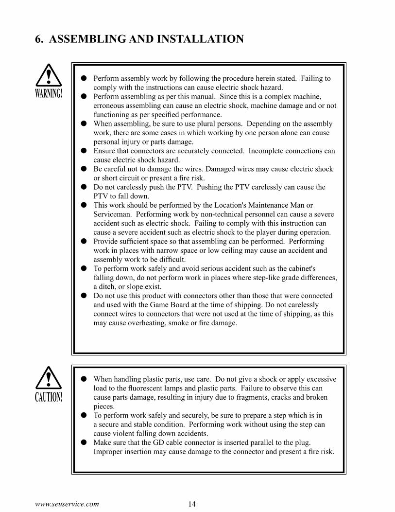
Connect the wire connector on the pedal and the wire connector on the foot base and secure wires with the cord clamp.
Connect the connector.
PHOTO 6. 2 h
CORD CLAMP
Attach the pedal with 4 hexagonal bolts.
PHOTO 6. 2 i
Reattach the pedal base lid as it was before.
PHOTO 6. 2 j
PEDAL BASE LID
HEXAGONAL BOLT (4)M6×16, w/spring washer, flat washer used
SCREW (4), blackM4×8, w/flat & spring washers

20www.seuservice.com 21 www.seuservice.com
SECURING IN PLACE(ADJUSTER TUNING)
Make sure that all of the adjusters are in contact with the floor. If they are not, the cabinet can move and cause an accident.
This machine has 4 casters and 4 adjusters. When the installation position is determined, cause the adjusters to come into contact with the floor directly, make adjustments in a manner so that the casters will be raised approximately 5 mm. from the floor and make sure that the machine position is level.
Move the machine to the installation position.
Cause all of the adjusters to make contact with the floor. By using a wrench, make adjustments in the height of the adjusters to ensure that the machine's position is level.
After making adjustments, fasten the adjuster nut up-ward and secure the height of the adjuster.
Check the pedal base plate attachment. If it has been attached too tightly or too loose, remove the pedal base lid, loosen the pedal-securing hexagonal bolts, and cor-rect the position of the pedal.
FIG. 6. 3 a BOTTOM VIEW
FIG. 6. 3 b ADJUSTER
FIG. 6. 3 dProvide sufficient space so as to allow for ventilation by the ventilation fan.
FIG. 6. 3 cRefer to this Fig. (Scale:1/100) for the layout of the place of installation.
CASTER
ADJUSTER
Approx.5mm
ADJUSTER
Fasten Upward.
CASTER
ADJUSTER
1.4 m (4.6 ft)
10
cm
(3
.9 in
)
2.0
m (
6.6
ft)
4.6 ft
3.9
in
6.6
ft
3

20www.seuservice.com 21 www.seuservice.com
INSTALLING THE GD-ROM DRIVE (SETTING THE GD-ROM DISC)
Carefully handle the GD-ROM drive so as not to contaminate the disc and the readout lens with stains and dust particles.
Do not continue to use the scratched GD-ROM disc. The scratched GD-ROM disc may cause the system to malfunction.
Set the GD-ROM disc onto the GD-ROM drive with its labeled side facing upward.
The key chip is a precision device. Handle it carefully and avoid exposure to heat, shock and static electricity, as these may cause damage to the device.
The key chip is contained in the GD-ROM disc case. Always use them as a set.
Unpack the shipping crate, and take out the GD-ROM drive, GD-ROM drive bracket, and GD-ROM disc.
GD DRIVE BRACKET GD-ROM DRIVE
PHOTO 6. 4 a
Use the 4 tapping screws to fix the GD-ROM drive bracket onto the GD-ROM drive. Be careful about a fixing direction.
TAPPING SCREW (4)4×8
FIG. 6. 4 a
GD DRIVE BRACKET
GD-ROM DRIVE
FIG. 6. 4 b
CAUTION for U. S. A., Europe, and Australia:Attach the 2 caution stickers for a laser ray onto the GD-ROM drive.
4
STOPIMPORTANT!

22www.seuservice.com 23 www.seuservice.com
Remove the 1 truss head screw that fixes the GD-ROM drive lid (DISC LID). And turn clockwise the lid to remove.
TRUSS SCREW (1)M3×8
PHOTO 6. 6 b
Set the GD-ROM disc onto the GD-ROM drive with its labeled side facing upward.
Return the lid to its original place, and fix it with 1 truss head screw. Be careful not to fasten the screw too tightly.
TRUSS SCREW (1) M3×8
PHOTO 6. 6 c

22www.seuservice.com 23 www.seuservice.com
Unlock the front-left door, and thereby remove the door from the cabinet.
Now you will take out the ASSY MAIN BD from the cabinet and mount the GD-ROM drive onto it. First, remove the 8 connectors from the upper section of the rear of the door.
Unlock.
PHOTO 6. 4 d
Disconnect the connector.
PHOTO 6. 4 e

24www.seuservice.com 25 www.seuservice.com
Remove the 2 wing bolts securing the ASSY MAIN BD base (a wooden plate).
Pull the ASSY MAIN BD out about 30 cm from the Cabinet. Be careful not to dam-age the wiring at this time.
PHOTO 6. 4 g
Disconnect the connector on the lower part of the inside of the door.
PHOTO 6. 4 f
PHOTO 6. 4 h
Disconnect the connector.
WING BOLT (2)M4×30, flat washer used

24www.seuservice.com 25 www.seuservice.com
D-SUB CONNECTOR
GD CABLE CONNECTOR
POWER CORD CONNECTOR
FLANGE NUT (4)M4
Unplug the D-SUB connector from the side of the Game Board on the ASSY MAIN BD.
Pull the ASSY MAIN BD out of the Cabinet and set it on a level surface before continuing with the following procedure.
Set the GD-ROM drive onto the ASSY MAIN BD. Tighten the 4 flange nuts to fix the ASSY MAIN BD.
Insert both the GD cable connector (for data communication) and the power connector (JST NH6P) into the GD-ROM drive. Be careful about an inserting direction in this instance. Make sure that the connectors are inserted firmly and completely.
PHOTO 6. 4 j
PHOTO 6. 4 i
PHOTO 6. 4 k

26www.seuservice.com 27 www.seuservice.com
Insert the Key Chip directly into the hole on the side of the Media Board, located on the upper part of game board. Make sure that the key chip is aligned properly and push it all the way in.
Affix the enclosed stickers to the Game Board. Affix the 843-****D-02 sticker to the Main Board and the 843-****B sticker to the Media Board. Place the both stickers on top of the stickers al-ready affixed.
FIG. 6. 4 c
Return the ASSY MAIN BD to the Cabinet with the GD-ROM DRIVE installed. In the reverse of the previous stated procedure, connect the D-SUB connector with the ASSY MAIN BD sticking out about 30 cm from the Cabinet. Then fasten the base with 2 wing bolts and insert connectors.
PHOTO 6. 4 L
MAIN BOARD
PROJECTION
KEY CHIP
MEDIA BOARD
KEY CHIP

26www.seuservice.com 27 www.seuservice.com
To the Power SupplySocket outlet
Main SW off.
MAIN SW
EARTH TERMINAL <For Taiwan>
Connect with the indoor earth termina
AC CABLE (POWER CORD)CIRCUIT PROTECTOR
INLET
POWER SUPPLY, AND EARTH CONNECTION
FIG. 6. 7 a AC UNIT
The AC Unit is located on one side of Cabinet. The AC Unit has Main SW, Earth Terminal and the Inlet which connects the Power Cord.
Ensure that the Main SW is OFF.
Be sure to independently use the power supply socket outlet equipped with an Earth Leakage Breaker. Using a power supply without an Earth Leakage Breaker can cause a fire when electric leakage occurs.
Ensure that the "accurately grounded indoor earth terminal" and the earth wire cable are available (except in the case where a power cord plug with earth is used). This product is equipped with the earth terminal. Connect the earth terminal and the indoor earth terminal with the prepared cable. If the ground-ing work is not performed appropriately, customers can be subjected to an electric shock, and the product's functioning may not be stable.
Ensure that the power cord and earth wire are not exposed on the surface (pas-sage, etc.). If exposed, they can be caught and are susceptible to damage. If damaged, the cord and wire can cause electric shock and short circuit acci-dents. Ensure that the wiring position is not in the customer's passage way or the wiring has protective covering.
After wiring power cord on the floor, be sure to protect the power cord. Ex-posed power cord is susceptible to damage and causes an electric shock ac-cident.
WARNING!
Note: Image may differ from actual unit.
5

28www.seuservice.com 29 www.seuservice.com
Firmly insert the power plug into the socket outlet.
Insert the opposite side of Power Cord plug to the AC Unit's con-nector ("INLET").
Perform wiring for the Power Cord and Earth Wire. Install protective covering for the Power Cord and Earth Wire.
Connect one end of the earth wire to the AC Unit earth terminal, and the other end to the indoor earth terminal. The AC Unit earth terminal has a Bolt and Nut combi-nation. Take off the Nut, pass the end of earth wire through the Bolt, and fasten the Nut. <For Taiwan>
*Note that the Earth Wire is incorporated in the Power Cord for the Areas of AC 120 V (USA) and AC 220~240 V, and there-fore, this procedure is not necessary.
WIRING COVER
In case the Power Plug is apt to come out of place, secure the Power Cord to the periphery of the AC Unit with the Cord Clamp (an accessory).
FIG. 6. 7 d HOW TO USE THE CORD CLAMP
FIG. 6. 7 c Connecting Power Cord and Earth Wire
Connect the Earth Wireto the Earth Terminal.
FIG. 6. 7 b *Earth Wire Connection

28www.seuservice.com 29 www.seuservice.com
TURNING POWER ON
Turn on the AC unit's main switch to connect the power. When the power is connected, the fluorescent light in the billboard becomes on. A few seconds later a system startup screen appears and then an advertising screen (plying for a player screen) appears.
Time until displaying an advertising screen is not constant; it varies from some tens of second up to several minutes. This is due to the functional characteristics of the GD-ROM system's rechargeable battery and therefore normal.
When an advertising screen appears, sound is output from the speakers on the right and left of the PTV cabinet. Sound is not output if you have set the function to off.After the power is disconnected, the system can maintain the data of credit number and ranking. The system cannot maintain, however, the fractional number of coins (not enough for one credit) and the bonus adder count data.
FIG. 6. 6
Fluorescent lamp (in the Billboard) is lit.
On-screen images are outputted.
Sound is emitted.
6

30www.seuservice.com 31 www.seuservice.com
ASSEMBLING CHECK
In the TEST MODE, ensure that the assembly has been made correctly and IC BD. is satisfactory (refer to Section 9).In the test mode, perform the following test:
MEMORY TEST
When "MEDIA BOARD TEST" is selected from the System Test Mode Menu Screen the Game Board memory is automatically tested. If the display beside each memory reads "GOOD", the Game Board is functioning correctly. Also, when "SYSTEM INFORMATION" is selected, Main Board and Media Board data for the Game Board are displayed. If data is displayed correctly, the Game Board is functioning cor-rectly.
MEDIA BOARD TEST screen
SYSTEM INFORMATION screen
����MEDIA�BOARD�TEST
����DIMM�BOARD(TYPE3)����VERSION��****����STATUS���GOOD����CHECKING�100%
����DIMM�TEST����DIMM0�������GOOD����DIMM1�������NONE����GD-ROM������GOOD
PRESS�TEST�BUTTON�TO�EXIT
����SYSTEM�INFORMATION
��MAIN�BOARD����REGION������������****����BOOT�VERSION������****����QC�FIRM�VERSION���****����SC�FIRM�VERSION���****����SERIAL�NO.�***************
��MEDIA�BOARD����DIMM�BOARD(TYPE3)�+�GDROM����MEMORY�SIZE�������512MB����FIRM�VERSION������****����SERIAL�NO.�***************
PRESS�TEST�BUTTON�TO�EXIT
8

30www.seuservice.com 31 www.seuservice.com
C.R.T. TEST
In the TEST mode menu, selecting C.R.T. TEST allows the screen (on which the pro-jector is tested) to be displayed. Although the projector adjustments have been made at the time of shipment from the factory, make judgment as to whether an adjustment is needed by watching the test mode screen. If it is necessary, adjust the projector by re-ferring to Section 11.
Selecting the INPUT TEST on the game test mode menu screen causes the screen (on which each switch is tested) to be displayed. Press each switch. If the display beside each switch indicates "ON," the switch and wiring connections are satisfactory.
������������������C.R.T.�TEST��1/2
�����1����������������������������������32
RED
GREEN
BLUE
WHITE
PRESS�TEST�BUTTON�TO�CONTINUE
�����������������C.R.T.�TEST��2/2
PRESS�TEST�BUTTON�TO�EXIT
INPUT TEST
��������������INPUT�TEST
���������PLAYER������1������2���������TRIGGER����OFF����OFF���������CHANGE�����OFF����OFF���������PEDAL������OFF����OFF���������GUN-X������00H����00H���������GUN-Y������00H����00H���������SCREEN������IN�����IN���������START������OFF����OFF
���������SERVICE��������OFF���������TEST�����������OFF
PRESS�TEST�AND�SERVICE�BUTTON�TO�EXIT
32www.seuservice.com 33 www.seuservice.com
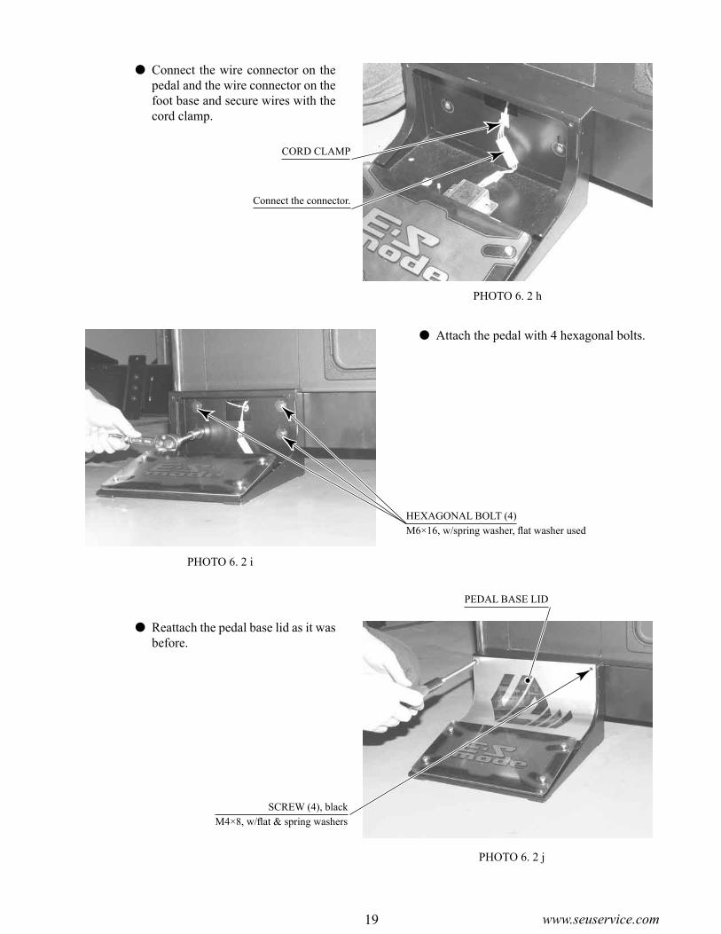
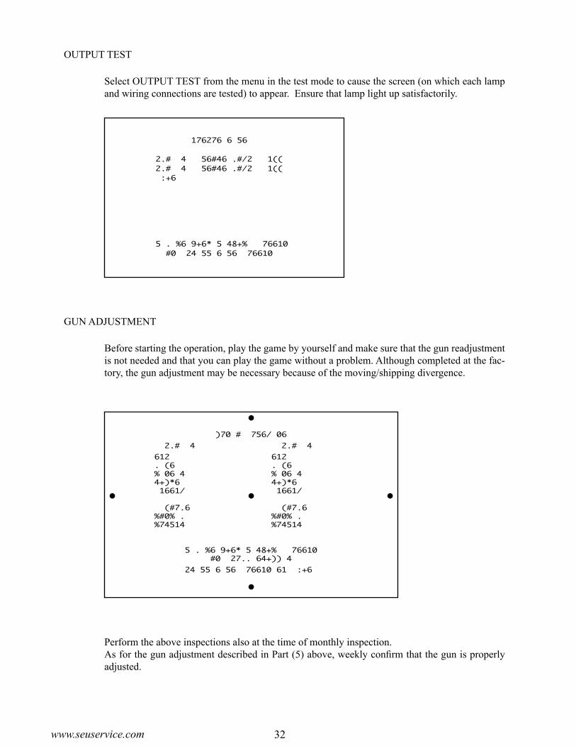
OUTPUT TEST
Select OUTPUT TEST from the menu in the test mode to cause the screen (on which each lamp and wiring connections are tested) to appear. Ensure that lamp light up satisfactorily.
Perform the above inspections also at the time of monthly inspection.As for the gun adjustment described in Part (5) above, weekly confirm that the gun is properly adjusted.
GUN ADJUSTMENT
Before starting the operation, play the game by yourself and make sure that the gun readjustment is not needed and that you can play the game without a problem. Although completed at the fac-tory, the gun adjustment may be necessary because of the moving/shipping divergence.
����������OUTPUT�TEST
���PLAYER�1�START�LAMP���OFF���PLAYER�2�START�LAMP���OFF->�EXIT
���SELECT�WITH�SERVICE�BUTTON�����AND�PRESS�TEST�BUTTON
���������������GUN�ADJUSTMENT
�����PLAYER�1���������������PLAYER�2
->�TOP�������5��233����->�TOP�������5��233���LEFT���-318���17�������LEFT���-318���17���CENTER��-10���15�������CENTER��-10���15���RIGHT���242���34�������RIGHT���242���34���BOTTOM��-10�-204�������BOTTOM��-10�-204
���DEFAULT����������������DEFAULT���CANCEL�����������������CANCEL���CURSOR�����������������CURSOR
���������SELECT�WITH�SERVICE�BUTTON��������������AND�PULL�TRIGGER
���������PRESS�TEST�BUTTON�TO�EXIT

32www.seuservice.com 33 www.seuservice.com
When the game machines of a same or similar type are installed side by side, their sensors may interfere with each other. To reject the interference, follow the procedure below.The following game machines employ a same or similar type of sensor. If interference happens to the sensors, operation of the games may be mutually disturbed.
THE HOUSE OF THE DEAD 2, U/R type, DX type and Super DX type
THE LOST WORLD, U/R type, DX type and Super DX type
BRAVE FIRE FIGHTERS
CONFIDENTIAL MISSION, U/R type and DX type
THE MAZE OF THE KINGS, U/R type and DX type
THE HOUSE OF THE DEAD 3, U/R type and DX type
VIRTUA COP 3, U/R type and DX type
PHOTO 6. 7
In order to prevent electric shock and short circuit hazards, be sure to turn power off before performing work.
Be careful not to damage the wires. Damaged wires may cause electric shock or short circuit or present a fire risk.
Do not expose the IC BD, etc. without a good reason. Failure to observe this can cause electric shock hazard or malfunctioning.
Work should be performed by the Location's Maintenance Man or technical personnel. Performing work by those who do not have technical knowledge and expertise can cause electric shock accident or malfunctioning.
THE INTERFERENCE PREVENTION WIRING
INTERFERENCE PREVENTION WIRINGSMB-60028
If the game machines of a same or similar type are installed side by side, place them alternately (place the machine with an interference rejection wire next to the machine without).
Disconnect the power.
Unlock the front-left door, and thereby remove the door from the cabinet.
Locate an interference prevention wire inside the cabinet.
WARNING!

34www.seuservice.com 35 www.seuservice.com
GRIP PORTION
Have casters make contact with the floor.
7. PRECAUTIONS TO BE HEEDED WHEN MOVING THE MACHINE
When moving the machine, be sure to unplug the power plug. Moving the machine with the plug as is inserted can damage the power cord, and cause fire and electric shock hazards.
When moving the machine on the floor, retract the Adjusters and ensure that Casters make contact with the floor. During transportation, pay careful atten-tion so that Casters do not tread power cords and earth wires. Damaging the power cords can cause electric shock and short circuit hazards.
When moving the product, do not push the Front Glass. The Glass part could be damaged and glass fractions may cause injury.
When lifting the cabinet, be sure to hold the grip portions or bottom part. Failure to observe this may damage parts and cause injury.
Do not move the product with a GD-ROM disc inside. Remove the GD-ROM disc before moving the product.
Failure to observe this instruction may cause the GD-ROM disc and/or GD-ROM drive to be damaged.
When moving the machine, be sure to remove the foot pedals. Moving with the foot pedals may cause an accident, and deform or damage the part/floor.
FIG. 7
Do not hold or press these hatched parts to move the product.
WHEN MOVING THE PRODUCT,DO NOT PUSH THE FRONT GLASS.
CAUTION!
WARNING!

34www.seuservice.com 35 www.seuservice.com
GUN CONTROLLER
CABINET
FIG. 8
8. GAME CONTENTSThe following explanations apply to the case the product is functioning satisfactorily. Should there be any moves different from the following contents, some sort of faults may have occurred. Immediately look into the cause of the fault and eliminate the cause thereof to ensure satisfactory operation.
While the power is connected, the fluorescent light in the billboard is on and demonstration images and ranking data are displayed. During this advertising period, sound is also output from the speakers on the right and left of the cabinet. Sound is not output if you have set the function to off.Each of the right and left start buttons is integrated with a light. The light flashes when coins are inserted sufficiently for a play. The light goes out when the start button is pressed to start the game.

36www.seuservice.com 37 www.seuservice.com
Virtua Cop 3 has two main characters, RAGE (1P) and SMARTY (2P). JANET appears as an allied character during the game but cannot be controlled.
1P Character: RAGE
Strong as an ox and just as uncontrollable, this hothead tends to act before he thinks. That's made him something of a headache for the department.
2P Character: SMARTY
Rage's complete opposite, Smarty is a cautious, brainy type who never loses his cool. He's also the best marksman in the precinct.
The Main Characters

36www.seuservice.com 37 www.seuservice.com
⑥
①②
③
④
⑤
Playing Virtua Cop 3
A) Start a New Game
Press the START button to begin a new game. Mission Select follows.
B) Calibrating at the Start of the Game
The availability of calibration at the start of each game may be set in Test Mode. The following applies when calibration on demand is enabled.
To enter the calibration screen, hold down the foot pedal, aim the gun controller at the screen, and press the START button when starting the game. Aim the gun at the center target and pull the trigger. When calibration is complete, press the START button to exit to Mission Select.
C) Mission Select
Displays the three mission panels, Simple, Normal and Hard. Shoot the desired mission panel to start. Players are free to start any mission they like.
When a mission has been completed, the game returns to Mission Select. The mission panel for the completed mission reads "Complete" and cannot be selected. Select a different mission.
D) Game Screen
I Points/Point Multiplier Meter Total points earned are indicated by the eight digit number. After 3-point shots, Justice shots,
and other special attacks the name of the attack and points earned are shown beneath the score display.
The more enemies you shoot, the more the gauge above the score display lengthens. When the gauge is completely filled, your level increases. The current level is shown inside the circle. A higher level means more points for killing enemies, but you'll lose a level if you take damage or shoot a civilian!
II Lock-On Sight The Lock-On Sight automatically detects armed enemies and tells you when you're being
attacked. The Lock-On Sight can lock on multiple enemies simultaneously. When the sight appears, enemies are attacking. If you don't fight back, you're sure to take damage.
I
II
III
IV
V
VI

38www.seuservice.com 39 www.seuservice.com
III Bullets Left/Reload Shows bullets remaining in current gun. Shoot the gun away from the screen to reload your weapon.
IV Weapon Palette, Weapon Change The player starts out with a Guardian II (10-round magazine, infinite reloads). Defeat special
enemies and destroy background objects to get special weapons. Acquiring a special weapon will add a second weapon to the Weapon Palette. Use the Weapon Change button to switch between the special weapon and the Guardian II. The weapon currently in use is shown on top, above the weapon in stock. Special weapons can only be reloaded a limited number of times and cannot be reloaded once ammunition runs out. Get Ammo items to increase the number of times the weapon may be reloaded.
Special Weapons can be lost in three ways:
• When the reload count hits zero and all ammunition is used up
• When shot and hurt by an enemy
• By shooting a civilian
Knowing when to use which weapon is key.
After acquiring a special weapon, then another special weapon is acquired, it will be replaced old one.
V Life Shows life remaining. Getting shot by an enemy costs one life. Shooting a civilian also costs
one life. When all lives have been used up, the game is over.
VI ES Gauge Shows remaining energy in ES Mode. The ES Gauge falls during ES Mode and recovers
when you defeat enemies.
E) ES Mode (Exceeding Sense Mode)
Hold down the foot pedal to activate ES Mode.
ES Mode enhances your character's senses, making time appear to move slower.
In ES Mode you can even see your enemies' bullets and shoot them down before they reach you.
Red bullets are especially damaging, so try to get them before they get you!
ES Mode consumes the ES Gauge. When the ES Gauge runs out of energy, you will be unable to use ES Mode.
Kill enemies to recover energy for the ES Gauge.

38www.seuservice.com 39 www.seuservice.com
F) ES Attack (Exceeding Sense Attack)
ES Attack begins automatically in certain scenes.
ES Attack displays special targeting sights that show points of particular vulnerability for a limited time. Speed and accuracy are essential.
Hit all the targeted areas within the time given to clear the ES Attack. The outcome of an ES Attack affects the rest of the game's story.
When targets are shown with energy gauges, shoot until the energy gauge hits zero to clear the ES Attack.
G) Game Over
The game ends in one of three ways:
• When all lives have been lost
• When all three missions have been completed
• When the special "Extra Mission"(*) has been completed
(*) When both the Simple and Normal missions have been completed successfully (in either order) and the player defeats the boss of the Hard mission, a special scene is shown and the Extra Mission is unlocked.
H) Continue
When you run out of lives, "Continue" appears on the screen and a countdown begins. To continue, insert sufficient coins and press the START button. If enough credits remain to continue, press the flashing START button.
40www.seuservice.com 41 www.seuservice.com
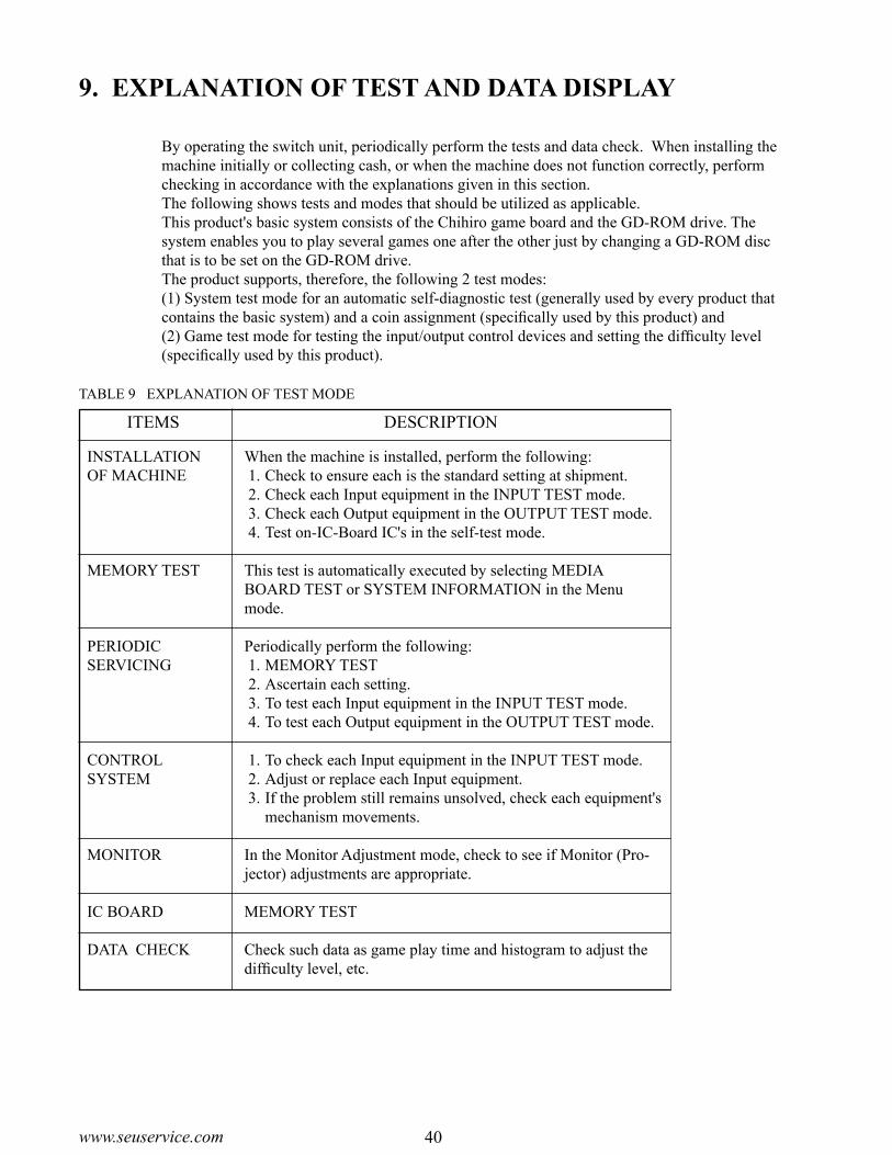
9. EXPLANATION OF TEST AND DATA DISPLAY
By operating the switch unit, periodically perform the tests and data check. When installing the machine initially or collecting cash, or when the machine does not function correctly, perform checking in accordance with the explanations given in this section.The following shows tests and modes that should be utilized as applicable.This product's basic system consists of the Chihiro game board and the GD-ROM drive. The system enables you to play several games one after the other just by changing a GD-ROM disc that is to be set on the GD-ROM drive. The product supports, therefore, the following 2 test modes:(1) System test mode for an automatic self-diagnostic test (generally used by every product that contains the basic system) and a coin assignment (specifically used by this product) and (2) Game test mode for testing the input/output control devices and setting the difficulty level (specifically used by this product).
9-3C
9-3A
9-3B
9-2B, C
9-2B, C
9-2B, C
9-3C, D
9-3A
9-3B
9-3A
9-3D
10
9-2F
11
9-2B, C
9-3E
TABLE 9 EXPLANATION OF TEST MODE
ITEMS DESCRIPTION
INSTALLATION OF MACHINE
MEMORY TEST
PERIODICSERVICING
CONTROL SYSTEM
MONITOR
IC BOARD
DATA CHECK
When the machine is installed, perform the following: 1. Check to ensure each is the standard setting at shipment. 2. Check each Input equipment in the INPUT TEST mode. 3. Check each Output equipment in the OUTPUT TEST mode. 4. Test on-IC-Board IC's in the self-test mode. This test is automatically executed by selecting MEDIA BOARD TEST or SYSTEM INFORMATION in the Menu mode.
Periodically perform the following: 1. MEMORY TEST 2. Ascertain each setting. 3. To test each Input equipment in the INPUT TEST mode. 4. To test each Output equipment in the OUTPUT TEST mode.
1. To check each Input equipment in the INPUT TEST mode. 2. Adjust or replace each Input equipment. 3. If the problem still remains unsolved, check each equipment's
mechanism movements.
In the Monitor Adjustment mode, check to see if Monitor (Pro-jector) adjustments are appropriate.
MEMORY TEST
Check such data as game play time and histogram to adjust the difficulty level, etc.
REFERENCESECTIONS

40www.seuservice.com 41 www.seuservice.com
9-1 SWITCH UNIT AND COIN METER
FIG. 9. 1 b
FIG. 9. 1 a SWITCH UNIT
Never touch places other than those specified. Touching places not specified can cause electric shock and short circuit accidents.
Adjust the sound to the optimum volume, taking into consideration the environmental requirements of the installation location.
Removing the Coin Meter circuitry renders the game inoperable.
Open the coin chute door, and the switch unit shown will appear.The functioning of each SW is as follows:
SWITCH UNIT
(1)SOUND VOLUME SWITCH: Adjusts sound volume for all of the machines' Speakers. (SOUND VOLUME)
(2)SERVICE BUTTON: Gives credits without registering on the coin meter. (SERVICE)
(3)TEST BUTTON: For the handling of the test button, refer to the following pages. (TEST)
COIN METER
Open the Cashbox Door by using the key to have the Coin Meter appear underneath the Cashbox.
COIN METER
(1) (2) (3)
STOPIMPORTANT!
WARNING!

42www.seuservice.com 43 www.seuservice.com
SYSTEM TEST MODE
Any settings that are changed by users during TEST MODE are saved upon exiting TEST MODE with the EXIT command in the SYSTEM MENU. If the unit is powered off prior to exiting, changes to settings will not take effect.
You may not enter GAME TEST MODE while the unit is reading from or checking the GD-ROM. If error messages are displayed when exiting TEST MODE, you should power the unit off and on again.
In the manual for this product, "Media Board" and "DIMM" are one and the same.
Use with the specified settings. If settings other than those specified are used, inappropriate operations or malfunction may occur.
SYSTEM TEST MENU MODE
Press the TEST Button after powering on the unit to display the following SYSTEM MENU.
Press the SERVICE Button to move the cursor to the desired test item.
Move the cursor to the desired item and press the TEST Button to display each test screen.
Move the cursor to ENTER GAME TEST and press the TEST Button to enter the individual test menus for each game.
When testing is complete, move the cursor to EXIT and press the TEST Button. The game advertisement screen should be displayed.
System Test Mode can be used to check that the main circuit operations are correct, adjust Monitor color, and perform coin/credit settings.However, this product can only be used with the settings shown below.
SOUND TEST - OUTPUT TYPE: STEREO COIN ASSIGNMENTS - COIN CHUTE TYPE: COMMON - SERVICE TYPE: COMMON
SYSTEM MENU
MEDIA BOARD TEST SYSTEM INFORMATION JVS TEST SOUND TEST C.R.T. TEST COIN ASSIGNMENTS CLOCK SETTING NETWORK SETTING(CORE) NETWORK SETTING(MEDIA) ENTER GAME TEST [*******************] EXIT
SELECT WITH SERVICE BUTTON AND PRESS TEST BUTTON
STOPIMPORTANT!

42www.seuservice.com 43 www.seuservice.com
MEDIA BOARD TEST
Powering off the system during the MEDIA BOARD TEST with a DIMM BOARD will erase the game programme data. It may be necessary to reload the data.Always wait for the test to complete before attempting to exit.
MEDIA BOARD TEST begins immediately upon entering this test mode.
If "GOOD" is displayed to the right of each item, the MEDIA BOARD components are functioning properly.
After the test is complete, move the cursor to EXIT and press the TEST Button to return to the SYSTEM MENU screen.
MEDIA BOARD TEST is used to check the memory and IC on the MEDIA BOARD connected to the Chihiro. Test screens and test times may differ depending on the type of MEDIA BOARD connected to the unit. The following is the MEDIA BOARD TEST screen for a unit with a DIMM BOARD.
MEDIA BOARD TEST
DIMM BOARD(TYPE3) VERSION **** STATUS GOOD CHECKING 100%
DIMM TEST DIMM0 GOOD DIMM1 NONE GD-ROM GOOD
PRESS TEST BUTTON TO EXIT
STOPIMPORTANT!

44www.seuservice.com 45 www.seuservice.com
SYSTEM INFORMATION
Use SYSTEM INFORMATION to check version and other information for system programmes.Screens may differ depending on the type of MEDIA BOARD connected to the unit. The following is the SYSTEM INFORMATION screen for a unit with a DIMM BOARD.
Press the TEST Button to return to the SYSTEM MENU screen.
(A) REGION The COUNTRY CODE of the MAIN BOARD.
(B) BOOT VERSION, QC FIRM VERSION, SC FIRM VERSION Version information for the MAIN BOARD system programmes.
(C) SERIAL NO. Serial number of the MAIN BOARD.
(D) DIMM BOARD + GDROM Type of MEDIA BOARD. This example shows a DIMM BOARD with a GD-ROM
DRIVE connected.
(E) MEMORY SIZE Capacity of DIMM memory installed on the DIMM BOARD.
(F) FIRM VERSION Version information for the DIMM BOARD system programme.
(G) SERIAL NO. Serial number of the DIMM BOARD.
����SYSTEM�INFORMATION
��MAIN�BOARD����REGION������������****����BOOT�VERSION������****����QC�FIRM�VERSION���****����SC�FIRM�VERSION���****����SERIAL�NO.�***************
��MEDIA�BOARD����DIMM�BOARD�+�GDROM����MEMORY�SIZE�������512MB����FIRM�VERSION������****����SERIAL�NO.�***************
PRESS�TEST�BUTTON�TO�EXIT
(A)(B)(B)(B)(C)
(D)(E)(F)(G)

44www.seuservice.com 45 www.seuservice.com
JVS TEST is used to verify the specs of the I/O BOARD connected to the Chihiro and to run input tests.I/O BOARD specs are displayed initially.Screens may differ depending on the type of I/O BOARD connected to the unit.
JVS TEST
Use the SERVICE Button to move the cursor to the desired test item.
Move the cursor to INPUT TEST and press the TEST Button to enter the INPUT TEST screen for the I/O BOARD currently displayed.
When 2 or more I/O BOARDS are connected, move the cursor to NEXT NODE and press the TEST Button to enter the test screen for the next I/O BOARD. The lower the NODE number, the further away the node is from the Chihiro.
Move the cursor to EXIT and press the TEST Button to return to the SYSTEM MENU screen.
�����������JVS�TEST����������INPUT�TEST����������NEXT�NODE��������→EXITNODE�������****NAME�������****************�����������I/O�BD�JVS�����������Ver****�����������*********CMD�VER����1.1JVS�VER����2.0COM�VER����1.0SWITCH�����2�PLAYER(S)��13�BITSCOIN�������2�SLOTANALOG�����8�CHROTARY�����0�CHKEYCODE����0SCREEN�����X:0�Y:0�CH:0CARD�������0�SLOTHOPPER�OUT�0�CHDRIVER�OUT�6�CHANALOG�OUT�0�CHCHARACTER��CHARA:0�LINE:0BACKUP�����0��SELECT�WITH�SERVICE�BUTTON����AND�PRESS�TEST�BUTTON

46www.seuservice.com 47 www.seuservice.com
SOUND TEST
Use SOUND TEST to test sound output and to select the stereo/mono/surround setting.
Use the SERVICE Button to move the cursor to the desired test item.
Press the TEST Button to enter the selected item.
(A) OUTPUT TYPE(STEREO, MONO, SURROUND) Select the sound output from the I/O PANEL audio output interface setting among
STEREO, MONO and SURROUND.
(B) RIGHT/LEFT SPEAKER(ON, OFF) When set to "ON", the test sends a beep to each audio output interface. Only the word
"SPEAKER" is displayed when the OUTPUT TYPE is set to "MONO", and when set to "ON", the test sends the same beep to both the left/right audio output interfaces.
To test surround output, it is necessary to use a separate Audio Amp, and receive signal from a terminal not in use at the time of shipping.
Note: Not available with this product.
Move the cursor to EXIT and press the TEST Button to return to the SYSTEM MENU screen.
��������SOUND�TEST
��OUTPUT�TYPE�������STEREO��RIGHT�SPEAKER�����OFF��LEFT��SPEAKER�����OFF→EXIT
SELECT�WITH�SERVICE�BUTTON��AND�PRESS�TEST�BUTTON
(A)(B)(B)

46www.seuservice.com 47 www.seuservice.com
C.R.T. TEST
Use the C.R.T. TEST to adjust monitor colours and verify screen size.
COLOUR CHECK Screen
Monitor COLOUR CHECK screen is displayed initially. Each of the colours (red, green and blue) is darkest at the far left and gets progressively lighter
(32 steps) towards the right. Monitor brightness is set correctly if the white colour bar is black at the left edge and white at the
right edge.
Press the TEST Button to proceed to the next page.
SIZE CHECK Screen
Adjust the CHECK GRID so that the entire GRID is displayed on the screen.
Press the TEST Button to return to the SYSTEM MENU screen.
�����������������C.R.T.�TEST�1/2
�����1����������������������������������32RED
GREEN
BLUE
WHITE
���������PRESS�TEST�BUTTON�TO�CONTINUE
C.R.T.�TEST�2/2
PRESS�TEST�BUTTON�TO�EXIT

48www.seuservice.com 49 www.seuservice.com
COIN ASSIGNMENTS
Use COIN ASSIGNMENTS to set the credit rate for each coin inserted.
Use the SERVICE Button to move the cursor to the desired test item.
Press the TEST Button to change the setting or to open the detailed settings.
Move the cursor to EXIT and press the TEST Button to return to the SYSTEM MENU screen.
COIN CHUTE TYPE…COMMON COIN CHUTE TYPE…INDIVIDUAL
(A) COIN CHUTE TYPE(COMMON, INDIVIDUAL) Adjust settings according to the specs of the cabinet COIN CHUTE.
COMMON This is for cabinets where a single COIN CHUTE is used by multiple players. Coins inserted by each player are treated as common credits. Up to 2 COIN CHUTES (#1 and #2) may be used. The (C) COIN TO CREDIT RATE setting
for COIN CHUTE #1 and #2 may be set differently.
INDIVIDUAL This is for cabinets with individual COIN CHUTES for each player. Coins inserted by each player are treated as individual player credits. The (C) COIN TO CREDIT RATE setting is used by all COIN CHUTES.
(B) SERVICE TYPE(COMMON, INDIVIDUAL) Use this to set the function of each SERVICE Button when there is more than one SERVICE
Button.
COMMON Pressing any SERVICE Button enters service credits for all players.
INDIVIDUAL Pressing the SERVICE Button enters service credits only for the corresponding player.
���������COIN�ASSIGNMENTS
��COIN�CHUTE�TYPE�������COMMON��SERVICE�TYPE����������COMMON
��COIN�CHUTE�#1�COIN�TO�CREDIT�RATE��1�COIN(S)�COUNT�AS�1�CREDIT(S)��COIN�CHUTE�#2�COIN�TO�CREDIT�RATE��1�COIN(S)�COUNT�AS�1�CREDIT(S)��DETAIL�SETTING��GAME�COST�SETTING→EXIT
����SELECT�WITH�SERVICE�BUTTON������AND�PRESS�TEST�BUTTON
���������COIN�ASSIGNMENTS
��COIN�CHUTE�TYPE�������INDIVIDUAL��SERVICE�TYPE����������INDIVIDUAL
��COIN�CHUTE�#1�COIN�TO�CREDIT�RATE��1�COIN(S)�COUNT�AS�1�CREDIT(S)
��DETAIL�SETTING��GAME�COST�SETTING→EXIT
����SELECT�WITH�SERVICE�BUTTON������AND�PRESS�TEST�BUTTON
(A)(B)
(C)
(C)
(D)(H)

48www.seuservice.com 49 www.seuservice.com
(C) COIN TO CREDIT RATE Set the CREDIT RATE for each coin inserted. The "X COIN(S) COUNT AS Y CREDIT(S)" setting indicates that "Inserting X coins equals Y
credits". Set this to "FREE PLAY" to allow game play without credits. When (A) COIN CHUTE TYPE is set to "COMMON", COIN CHUTE #2 settings are restricted
to some extent by the settings for COIN CHUTE #1.
(D) DETAIL SETTING This mode allows for more detailed credit rate settings than the (C) COIN TO CREDIT RATE
setting. Changes made in DETAIL SETTING override any (C) COIN TO CREDIT RATE settings.
DETAIL SETTING Screen
COIN CHUTE TYPE…COMMON COIN CHUTE TYPE…INDIVIDUAL
(E) COIN CHUTE MULTIPLIER Use this to set how many coins will be counted for each coin inserted. The "1 COIN COUNT AS X COIN(S)" setting indicates that "Each coin will be counted as X coins". When the (A) COIN CHUTE TYPE is set to "COMMON", the setting may be set individually
for COIN CHUTE #1 and #2.
(F) BONUS ADDER Use this to set the number of coins calculated with the (E) COIN CHUTE MULTIPLIER
setting that need to be inserted to get 1 bonus coin. When the (A) COIN CHUTE TYPE is set to "COMMON", the sum of the coins for COIN CHUTE #1 and #2 is used for the calculation.
The "X COINS GIVE 1 EXTRA COIN" setting indicates that "For every X coins, 1 bonus coin is given".
Set this to "NO BONUS ADDER" to disable bonus coins entirely.
(G) COIN TO CREDIT Use this to set how many coins calculated with the (F) BONUS ADDER setting count as 1
credit. The "X COIN(S) 1 CREDIT" setting indicates that "Every X coins equals 1 credit."
���������COIN�ASSIGNMENTS����������DETAIL�SETTING��COIN�CHUTE�#1�MULTIPLIER����1�COIN�COUNT�AS�1�COIN(S)��COIN�CHUTE�#2�MULTIPLIER����1�COIN�COUNT�AS�1�COIN(S)��BONUS�ADDER���������NO�BONUS�ADDER��COIN�TO�CREDIT���1�COIN(S)�1�CREDIT→EXIT�COIN�CHUTE�#1�OPERATION�COIN���1��2��3��4��5��6��7��8��9�CREDIT�1��2��3��4��5��6��7��8��9�COIN�CHUTE�#2�OPERATION�COIN���1��2��3��4��5��6��7��8��9�CREDIT�1��2��3��4��5��6��7��8��9����SELECT�WITH�SERVICE�BUTTON������AND�PRESS�TEST�BUTTON
���������COIN�ASSIGNMENTS����������DETAIL�SETTING��COIN�CHUTE�#1�MULTIPLIER����1�COIN�COUNT�AS�1�COIN(S)
��BONUS�ADDER���������NO�BONUS�ADDER��COIN�TO�CREDIT���1�COIN(S)�1�CREDIT→EXIT�COIN�CHUTE�#1�OPERATION�COIN���1��2��3��4��5��6��7��8��9�CREDIT�1��2��3��4��5��6��7��8��9
����SELECT�WITH�SERVICE�BUTTON������AND�PRESS�TEST�BUTTON
(E)
(E)
(F)(G)

50www.seuservice.com
(H) GAME COST SETTING Use this mode to set the number of credits required to start a game. Screens may differ depending on the game.
(I) Set the number of credits required to start a game.
(J) Set the number of credits required to continue a game.
���������COIN�ASSIGNMENTS���������GAME�COST�SETTING
��1�CREDIT(S)�TO�START��1�CREDIT(S)�TO�CONTINUE
→EXIT
����SELECT�WITH�SERVICE�BUTTON������AND�PRESS�TEST�BUTTON
(I)(J)
CLOCK SETTING
Use CLOCK SETTING to set the Chihiro internal clock.
Use the SERVICE Button to move the cursor to the item to be set.
Move the cursor to the desired item and press the TEST Button to increase values. The max value for YEAR is "2099"; further increases return the value to "2000".
Move the cursor to EXIT and press the TEST Button to return to the SYSTEM MENU screen.
������CLOCK�SETTING
20XX/XX/XX(XXX)��XX:XX:XX
���������YEAR���������MONTH���������DAY���������HOUR���������MINUTE�������→EXIT
SELECT�WITH�SERVICE�BUTTON��AND�PRESS�TEST�BUTTON

51 www.seuservice.com
NETWORK SETTING (CORE)
Use the SERVICE Button to move the cursor to the desired test item. (When setting IP ADDRESS, SUBNET MASK, GAME WAY or PRIMARY DNS, use the
underline as a guide.)
Press the TEST Button to change the setting.
Move the cursor to EXIT and press the TEST Button to return to the SYSTEM MENU screen.
(A) REMOTE (C) This sets up whether a communication setting is automatic or manual. ENABLE: Sets the communication setting automatically. DISABLLE: Sets the communication setting manually.
(B) IP ADDRESS (C) This is one of the settings required for communication network. After setting the number, press
TEST Button on SET position to memorize the setting. If you set the REMOTE setting to ENABLE, you cannot select this.
(C) SUBNET MASK (C) This is one of the settings required for communication network. After setting the number, press
TEST Button on SET position to memorize the setting. If you set the REMOTE setting to ENABLE, you cannot select this.
(D) GATE WAY (C) This is one of the settings required for communication network. After setting the number, press
TEST Button on SET position to memorize the setting. If you set the REMOTE setting to ENABLE, you cannot select this.
(E) PRIMARY DNS (C) This is one of the settings required for communication network. After setting the number, press
TEST Button on SET position to memorize the setting. If you set the REMOTE setting to ENABLE, you cannot select this.
(F) CURRENT This displays the present setting value during a setup of each item [(B), (C), (D), (E)]. Pressing
TEST Button on SET position, the settings are memorized and the screen is changed.
Use the LAN PORT attached to the Main Board, and carry out the settings necessary for network communication.Note: This function is not available with this product.
����NETWORK�SETTING�(CORE)
->REMOTE(C)�������ENABLE��IP�ADDRESS(C)����---.---.---.---��SUBNET�MASK(C)����---.---.---.---��GATE�WAY(C)����---.---.---.---��PRIMARY�DNS(C)����---.---.---.---��EXIT
����CURRENT�************������***.***.***.***�SELECT�WITH�SERVICE�BUTTON���AND�PRESS�TEST�BUTTON
(A)(B)
(C)
(D)
(E)
(F)

52www.seuservice.com 53 www.seuservice.com
NETWORK SETTING (MEDIA)
Use NETWORK SETTING to establish and test network connections.This is only displayed the following error message screen. This game does not support network communication connections.
����NETWORK�SETTING(MEDIA)
�����COMMUNICATION�ERROR

52www.seuservice.com 53 www.seuservice.com
GAME TEST MODE
When changing the game configuration, changes will not take effect until the Game Test Mode has been completed. Be sure to exit the Game Test Mode properly after configuration changes.
FIG. 9. 3 GAME TEST MENUscreen
Performs tests, adjustments and settings for each of the Game Test Menu screen items below.
A. INPUT TEST: Tests each input device used in the game.
B. OUTPUT TEST: Tests each output device used in the game.
C. GAME ASSIGNMENTS: Adjusts game settings.
D. GUN ADJUSTMENT: Performs sight settings for the game's Control Unit (Gun).
E. BOOKKEEPING: View all recorded game data.
F. BACKUP DATA CLEAR: Erase all game records.
After selecting an item, read the explanations below regarding operation.
After performing tests and adjustments, return to the Game Test Menu screen, select EXIT and press the TEST Button.
You will return to the System Menu screen. Move the cursor to EXIT on the System Menu screen and press the TEST Button to return to the Game Play screen.
������GAME�TEST�MENU
�����INPUT�TEST�����OUTPUT�TEST�����GAME�ASSIGNMENTS�����GUN�ADJUSTMENT�����BOOKKEEPING�����BACKUP�DATA�CLEAR���->EXIT
SELECT�WITH�SERVICE�BUTTON��AND�PRESS�TEST�BUTTON
Select ENTER GAME TEST from the System Menu screen to display the Game Test Menu screen as follows.Use the SERVICE Button to move the cursor to the desired test item. Press the TEST Button to enter the selected item's test.
STOPIMPORTANT!

54www.seuservice.com 55 www.seuservice.com
FIG. 9. 3 a INPUT TEST screen
��������������INPUT�TEST
���������PLAYER������1������2���������TRIGGER����OFF����OFF���������CHANGE�����OFF����OFF���������PEDAL������OFF����OFF���������GUN-X������00H����00H���������GUN-Y������00H����00H���������SCREEN������IN�����IN���������START������OFF����OFF
���������SERVICE��������OFF���������TEST�����������OFF
PRESS�TEST�AND�SERVICE�BUTTON�TO�EXIT
A. INPUT TEST
Select INPUT TEST to display the following screen and check the status of input devices.This test should be used periodically to check that each input device is functioning correctly.
The items refer to the following input devices.
TRIGGER: The gun triggers.
CHANGE: The controller's weapon change button.
PEDAL: The foot pedal.
GUN-X: Ranges between 00 and FF when controller is pointed at screen.
GUN-Y: Ranges between 00 and FF when controller is pointed at screen.
SCREEN: Point controller at screen to change from OUT to IN.
START: The player Start Buttons.
SERVICE: The SERVICE Button.
TEST: The TEST Button.
Input is normal if the display to the right of each item changes from OFF to ON when each input device is operated.
Input is normal if the display to the right of SCREEN changes from OUT to IN and GUN-X and GUN-Y show values between 00 and FF when the controller is pointed at the screen.
Press the SERVICE and TEST Buttons simultaneously to return to the Game Test Menu screen.

54www.seuservice.com 55 www.seuservice.com
FIG. 9. 3 b OUTPUT TEST screen(DELUXE TYPE)
����������OUTPUT�TEST
���PLAYER�1�START�LAMP���OFF���PLAYER�2�START�LAMP���OFF->�EXIT
���SELECT�WITH�SERVICE�BUTTON�����AND�PRESS�TEST�BUTTON
B. OUTPUT TEST
Select OUTPUT TEST to display the following screen and check the status of each lamp.This test should be used periodically to check that the lamps are functioning correctly.
Press the SERVICE Button to move the cursor and the TEST Button to select. Displays ON when selected. Actual screen may differ for depending on cabinet type.
Perform the tests as follows.
PLAYER 1 START LAMP: Lights up the 1P START button.
PLAYER 2 START LAMP: Lights up the 2P START button flash.
Move the cursor to EXIT and press the TEST Button to return to the Game Test Menu screen.
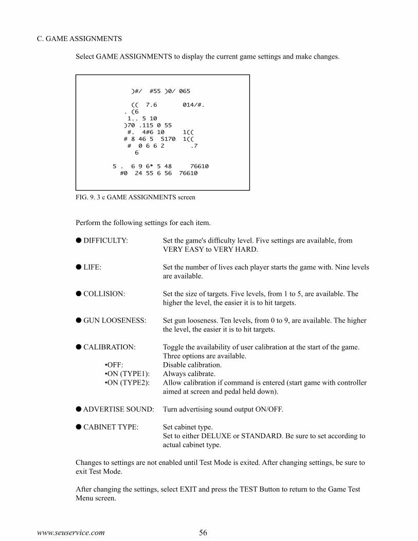
56www.seuservice.com 57 www.seuservice.com
FIG. 9. 3 c GAME ASSIGNMENTS screen
�����GAME�ASSIGNMENTS
���DIFFICULTY������NORMAL���LIFT������������3���COLLISION�������3���GUN�LOOSENESS���5���CALIBRATION�����OFF���ADVERTISE�SOUND�OFF���CABINET�TYPE����DELUXE->�EXIT
SELECT�WITH�SERVICE�BUTTON��AND�PRESS�TEST�BUTTON
C. GAME ASSIGNMENTS
Select GAME ASSIGNMENTS to display the current game settings and make changes.
Perform the following settings for each item.
DIFFICULTY: Set the game's difficulty level. Five settings are available, from VERY EASY to VERY HARD.
LIFE: Set the number of lives each player starts the game with. Nine levels are available.
COLLISION: Set the size of targets. Five levels, from 1 to 5, are available. The higher the level, the easier it is to hit targets.
GUN LOOSENESS: Set gun looseness. Ten levels, from 0 to 9, are available. The higher the level, the easier it is to hit targets.
CALIBRATION: Toggle the availability of user calibration at the start of the game. Three options are available.
•OFF: Disable calibration.•ON (TYPE1): Always calibrate.•ON (TYPE2): Allow calibration if command is entered (start game with controller
aimed at screen and pedal held down).
ADVERTISE SOUND: Turn advertising sound output ON/OFF.
CABINET TYPE: Set cabinet type. Set to either DELUXE or STANDARD. Be sure to set according to
actual cabinet type.
Changes to settings are not enabled until Test Mode is exited. After changing settings, be sure to exit Test Mode.
After changing the settings, select EXIT and press the TEST Button to return to the Game Test Menu screen.

56www.seuservice.com 57 www.seuservice.com
FIG. 9. 3 d GUN ADJUSTMENT screen
���������������GUN�ADJUSTMENT
�����PLAYER�1���������������PLAYER�2
->�TOP�������5��233����->�TOP�������5��233���LEFT���-318���17�������LEFT���-318���17���CENTER��-10���15�������CENTER��-10���15���RIGHT���242���34�������RIGHT���242���34���BOTTOM��-10�-204�������BOTTOM��-10�-204
���DEFAULT����������������DEFAULT���CANCEL�����������������CANCEL���CURSOR�����������������CURSOR
���������SELECT�WITH�SERVICE�BUTTON��������������AND�PULL�TRIGGER
���������PRESS�TEST�BUTTON�TO�EXIT
D. GUN ADJUSTMENT
Select GUN ADJUSTMENT to display the following screen.This screen allows you to adjust the gun using the five calibration targets (TOP, LEFT, CENTER, RIGHT, BOTTOM). Use each target to calibrate as follows.
Use the standard gun controller, carefully aim at the correct target and pull the trigger to calibrate the value. Select between the calibration targets with the 1P and 2P START buttons or SERVICE button.
Details for each item are as follows.
TOP x y: Set the TOP value. The number on the left (x) is the horizontal component, and the number
on the right (y) is the vertical component. Aim the controller at the TOP target (circle) and pull the trigger to set the value. This will not affect horizontal calibration.
LEFT x y: Set the LEFT value. The number on the left (x) is the horizontal component, and the number
on the right (y) is the vertical component. Aim the controller at the LEFT target and pull the trigger to set the value. This will not affect vertical calibration.
CENTER x y: Set the CENTER value. The number on the left (x) is the horizontal component, and the number
on the right (y) is the vertical component. Aim the controller at the CENTER target and pull the trigger to set the CENTER value.
RIGHT x y: Set the RIGHT value. The number on the left (x) is the horizontal component, and the number
on the right (y) is the vertical component. Aim the controller at the RIGHT target and pull the trigger to set the RIGHT value. This will not affect vertical calibration.
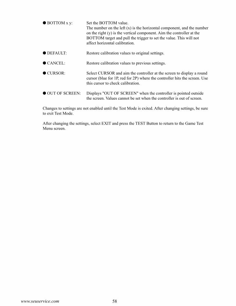
58www.seuservice.com 59 www.seuservice.com
BOTTOM x y: Set the BOTTOM value. The number on the left (x) is the horizontal component, and the number
on the right (y) is the vertical component. Aim the controller at the BOTTOM target and pull the trigger to set the value. This will not affect horizontal calibration.
DEFAULT: Restore calibration values to original settings.
CANCEL: Restore calibration values to previous settings.
CURSOR: Select CURSOR and aim the controller at the screen to display a round cursor (blue for 1P, red for 2P) where the controller hits the screen. Use this cursor to check calibration.
OUT OF SCREEN: Displays "OUT OF SCREEN" when the controller is pointed outside the screen. Values cannot be set when the controller is out of screen.
Changes to settings are not enabled until the Test Mode is exited. After changing settings, be sure to exit Test Mode.
After changing the settings, select EXIT and press the TEST Button to return to the Game Test Menu screen.

58www.seuservice.com 59 www.seuservice.com
FIG. 9. 3 e a BOOKKEEPING 1/3 screen
�������BOOKKEEPING��1/3
�COIN�CHUTE�#1�������������0�COIN�CHUTE�#2�������������0�TOTAL�COINS���������������0
�COIN�CREDITS��������������0�SERVICE�CREDITS�����������0�TOTAL�CREDITS�������������0
PRESS�TEST�BUTTON�TO�CONTINUE
E. BOOKKEEPING
Select BOOKKEEPING on the Game Test Menu screen to display the three screens of operating status data.Press the TEST Button on the BOOKKEEPING 1/3 and BOOKKEEPING 2/3 screens to move to the second and third (BOOKKEEPING 3/3) screens. Press the TEST Button in the third screen to return to the Game Test Menu screen.
The display items for the screen (Page 1 of 3) are as follows.
COIN CHUTE #1: The number of coins inserted into Coin Slot 1.
COIN CHUTE #2: The number of coins inserted into Coin Slot 2.
TOTAL COINS: The total number of coins inserted into the coin slots.
COIN CREDITS: The number of credits for the coins inserted.
SERVICE CREDITS: The number of credits input by the SERVICE Button.
TOTAL CREDITS: Total credits from coins and the SERVICE Button
Press the TEST Button to display the next screen.
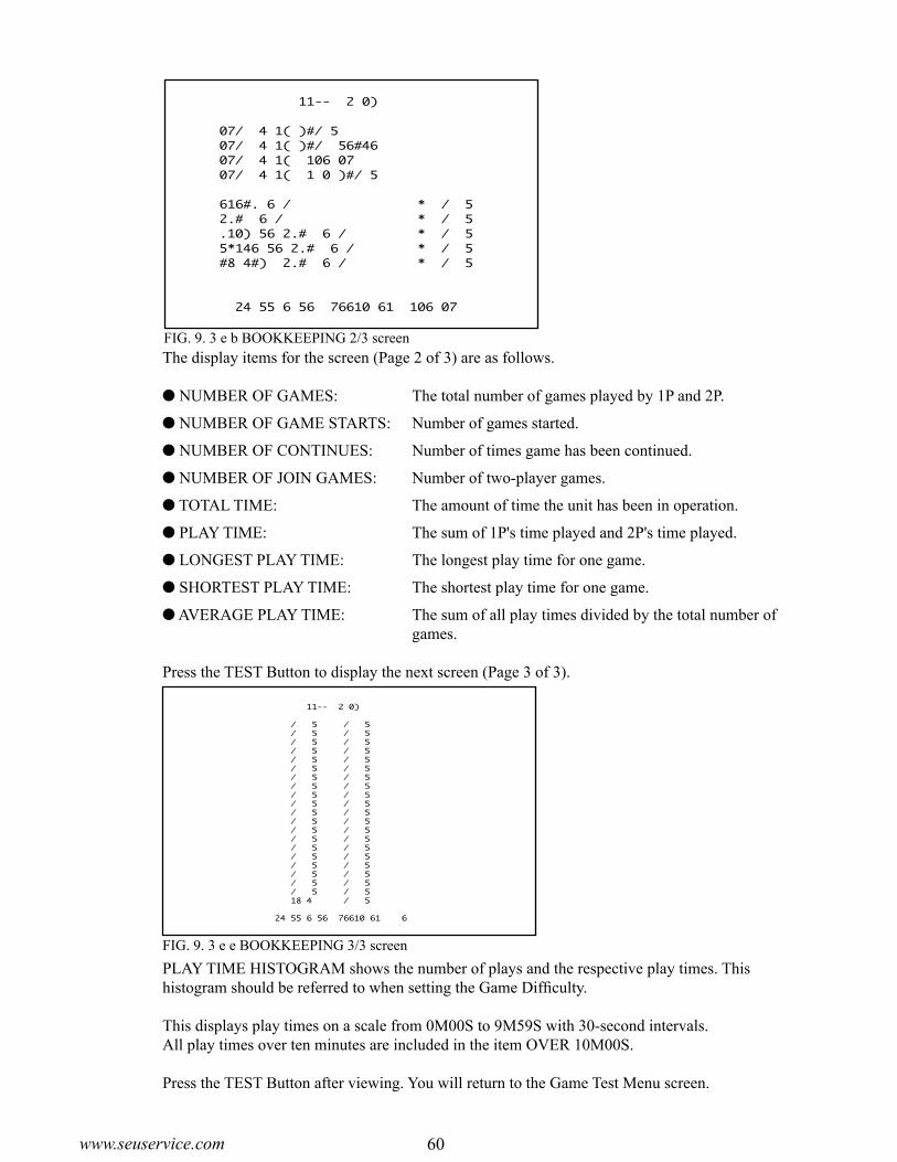
60www.seuservice.com 61 www.seuservice.com
FIG. 9. 3 e b BOOKKEEPING 2/3 screen
FIG. 9. 3 e e BOOKKEEPING 3/3 screen
���������BOOKKEEPING��2/3
NUMBER�OF�GAMES����������������3NUMBER�OF�GAME�START�����������3NUMBER�OF�CONTINUE�������������0NUMBER�OF�JOIN�GAMES�����������0
TOTAL�TIME�����������0D�0H10M49SPLAY�TIME������������0D�0H�1M55SLONGEST�PLAY�TIME�������0H�1M24SSHORTEST�PLAY�TIME������0H�0M14SAVERAGE�PLAY�TIME�������0H�0M38S
��PRESS�TEST�BUTTON�TO�CONTINUE
�����BOOKKEEPING��3/3
��0M�00S�~��0M�29S�����2��0M�30S�~��0M�59S�����0��1M�00S�~��1M�29S�����1��1M�30S�~��1M�59S�����0��2M�00S�~��2M�29S�����0��2M�30S�~��2M�59S�����0��3M�00S�~��3M�29S�����0��3M�30S�~��3M�59S�����0��4M�00S�~��4M�29S�����0��4M�30S�~��4M�59S�����0��5M�00S�~��5M�29S�����0��5M�30S�~��5M�59S�����0��6M�00S�~��6M�29S�����0��6M�30S�~��6M�59S�����0��7M�00S�~��7M�29S�����0��7M�30S�~��7M�59S�����0��8M�00S�~��8M�29S�����0��8M�30S�~��8M�59S�����0��9M�00S�~��9M�29S�����0��9M�30S�~��9M�59S�����0���OVER����10M�00S�����0
PRESS�TEST�BUTTON�TO�EXIT
The display items for the screen (Page 2 of 3) are as follows.
NUMBER OF GAMES: The total number of games played by 1P and 2P.
NUMBER OF GAME STARTS: Number of games started.
NUMBER OF CONTINUES: Number of times game has been continued.
NUMBER OF JOIN GAMES: Number of two-player games.
TOTAL TIME: The amount of time the unit has been in operation.
PLAY TIME: The sum of 1P's time played and 2P's time played.
LONGEST PLAY TIME: The longest play time for one game.
SHORTEST PLAY TIME: The shortest play time for one game.
AVERAGE PLAY TIME: The sum of all play times divided by the total number of games.
Press the TEST Button to display the next screen (Page 3 of 3).
PLAY TIME HISTOGRAM shows the number of plays and the respective play times. This histogram should be referred to when setting the Game Difficulty.
This displays play times on a scale from 0M00S to 9M59S with 30-second intervals. All play times over ten minutes are included in the item OVER 10M00S.
Press the TEST Button after viewing. You will return to the Game Test Menu screen.
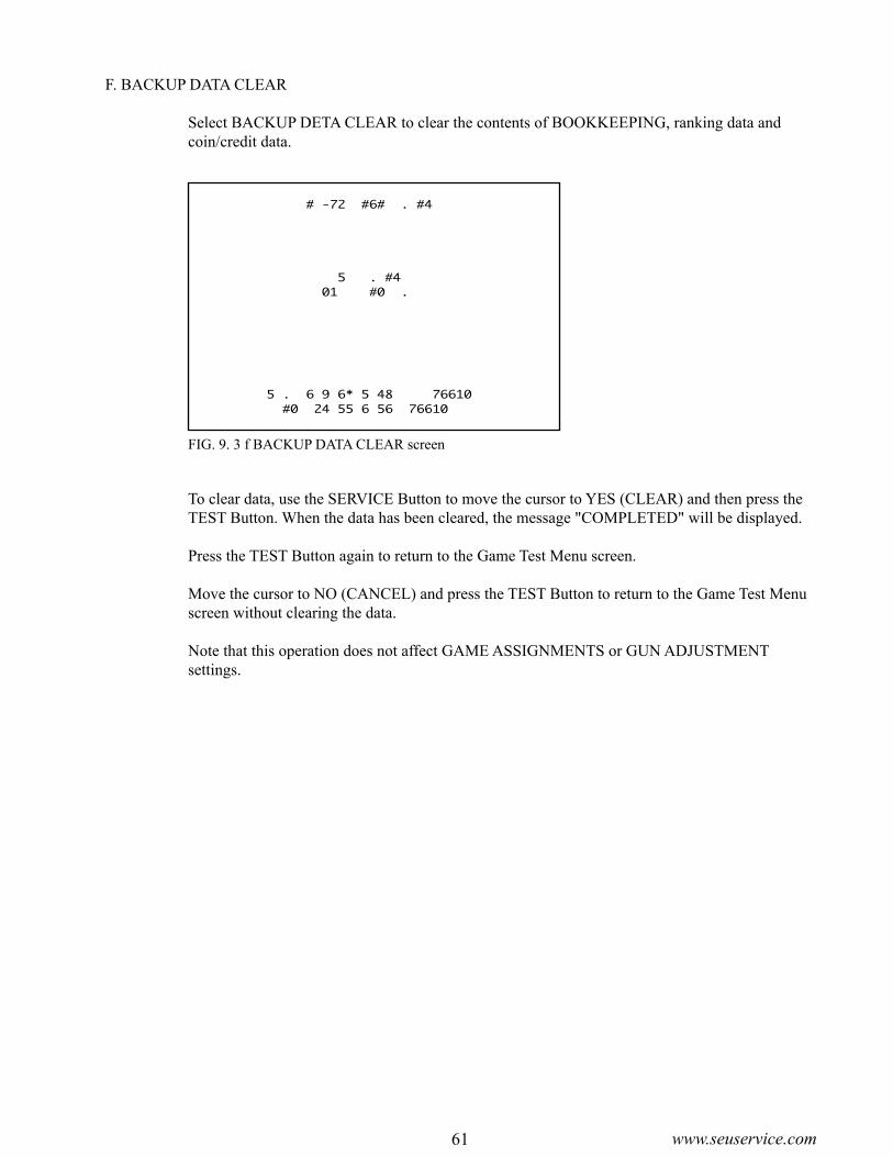
60www.seuservice.com 61 www.seuservice.com
FIG. 9. 3 f BACKUP DATA CLEAR screen
����BACKUP�DATA�CLEAR
�������YES�(CLEAR)����->�NO��(CANCEL)
SELECT�WITH�SERVICE�BUTTON��AND�PRESS�TEST�BUTTON
F. BACKUP DATA CLEAR
Select BACKUP DETA CLEAR to clear the contents of BOOKKEEPING, ranking data and coin/credit data.
To clear data, use the SERVICE Button to move the cursor to YES (CLEAR) and then press the TEST Button. When the data has been cleared, the message "COMPLETED" will be displayed.
Press the TEST Button again to return to the Game Test Menu screen.
Move the cursor to NO (CANCEL) and press the TEST Button to return to the Game Test Menu screen without clearing the data.
Note that this operation does not affect GAME ASSIGNMENTS or GUN ADJUSTMENT settings.

62www.seuservice.com 63 www.seuservice.com
In the cases where the gun's operation is not satisfactory or the gun sight deviates from the direction in which the control unit is pointed, the gun's interior parts may have been damaged. Replace the parts by disassembling the gun in the following procedure: Also, be sure to perform sighting check in the test mode when the gun parts are replaced.
Do not cut the tie belt securing the wires in the Control Unit (Gun Controller). Cutting the tie belt may cause malfunctioning of the wire connection. If you cut the tie belt when replacing the wire etc., be sure to secure the wires using a new tie belt as before.
Follow these directions carefully to avoid damaging or losing small parts.
10. CONTROL UNIT (GUN CONTROLLER)
In order to prevent an electric shock and short circuit, be sure to turn power off before performing work by touching the interior parts of the product.
Be careful not to damage the wires. Damaged wires may cause electric shock or short circuit or present a fire risk.
Be very careful when soldering. Handling a soldering iron carelessly may result in a fire or a burn.
When securing the plastic-made parts, do not excessively fasten screws and nuts. Failure to observe this may damage the parts and cause injury due to fragments resulting from damage.
When reassembling the Gun Controller, be sure to check the connecting portion and the trigger, etc. If the reassembling work is not sufficient and/or correct, it may cause injury resulting from catching fingers.
CAUTION!
STOPIMPORTANT!
WARNING!

62www.seuservice.com 63 www.seuservice.com
To replace the Gun Controller's internal components, first separate the left shell (Cover L) and right shell (Cover R). The controller's internal components are mounted on the right shell, so work with the gun lying on its right side. To replace the weapon change button microswitch, first remove the weapon change button from the right shell.
Turn power off.
Remove the 10 screws to separate the two shells.
PHOTO 10 a
With the right shell lying flat, carefully lift the left shell from the right shell.
PHOTO 10 b
COVER L
COVER R
REPLACING THE MICROSWITCH
SCREW (10), blackM3×10, w/small flat & spring washers

64www.seuservice.com 65 www.seuservice.com
Remove the trigger microswitch from the right shell.
PHOTO 10 c
Remove the soldering and detach the microswitch.
Remove the weapon change button from the right shell.
PHOTO 10 d
WEAPON CHANGE BUTTON
Remove the spring from the right shell.
PHOTO 10 e
SPRING
MICROSWITCH509-5080

64www.seuservice.com 65 www.seuservice.com
Remove 1 screw and detach the microswitch (with SW bracket attached) from the right shell.
PHOTO 10 f
Disconnect the microswitch wire connector.
PHOTO 10 g
Disconnect the connector.
Remove the 2 screws and remove the SW bracket from the microswitch.
PHOTO 10 h
SCREW (1)M3×8, w/flat & spring washers
SCREW (2)M2.3×10, w/flat & spring washers

66www.seuservice.com 67 www.seuservice.com
Remove the soldering and extract the microswitch.
Solder a new microswitch and rebuild the gun controller. Make sure that the wire in the right shell (Cover R) and the connector are wired as in the diagram before reattaching the left shell (Cover L) to the right shell. Also, be careful not to overtighten the screws.
Test the trigger and the weapon change button to make sure that the microswitch switches ON and OFF properly.
COVER L
MICROSWITCH
509-5080
WEAPONCHANGE BUTTON
SPRING
SCREW (1)
M3×8, w/flat & spring washer
SWITCH BRACKET
SCREW (2)
M2.3×10, w/flat & spring washers
SENSOR UNIT
JPT-2030
Disconnect the connector.
COVER R
SCREW (10), black
M3×10, w/small flat& spring washers
FIG. 10

66www.seuservice.com 67 www.seuservice.com
Follow the first 3 steps of "Replacing the Microswitch" to remove the left shell.
Detach the connector and pull out the sensor unit.
PHOTO 10 i
SENSOR UNITJPT-2030
Detach the connector.
REPLACING THE SENSOR UNIT

68www.seuservice.com 69 www.seuservice.com
Primary side and Secondary side The monitor's circuit which is divided into the Primary side
and Secondary side, is electrically isolated. Do not touch the primary side, or do not touch both the primary side and the secondary side simultaneously. Failing to observe the instruction can cause electric shock and this is very dangerous. When making monitor adjustments, use a non-conductive driver and make adjustment without touching any part other than the Adjustment V. R. and knob. Also, be sure not to cause a short-circuit to the Primary side and Secondary side. If short-circuited, it can cause electric shock or malfunctioning, which is very dangerous.
High-tension Voltage Some of the parts inside monitor are subject to high-tension voltage in excess of 20,000 volts and
very dangerous. Therefore, do not touch the monitor interior. Should soldering & paper wastes, etc. be mixed in the monitor interior, turn the power off so as not to cause malfunctioning or fire hazard.
Static Electricity Touching the CRT surface sometimes causes you to slightly feel electricity. This is because the
CRT surfaces are subject to static and will not adversely affect the human body. Installation and removal Ensure that the Magnetizer Coil, FBT (Fly-Back Transformer), Anode Lead and Focus Lead are
not positioned close to the sheet metal work's sharp edges, etc. and avoid damaging the insulated portions so as not to cause electric shock and malfunctioning. (For the name of parts, refer to the above Figures).
SECONDARY SIDE(Chassis, CRT)
ANODE LEADApprox. 29 kV
MAIN BD
FBT Approx. 29 kV
ANODE CAP
FOCUS LEAD (black)Approx. 10 kV
SECONDARY SIDE(Chassis, sheet metal work, CRT, etc.) Disconnect or unplug
NECK PCB
Approx. 10 kV
REAR PARTPRIMARY SIDE
Connecting the CRT and PCB For combining the CRT and PCB, use the specified part No. to maintain the status of adjustments
made at the factory. The anode of the CRT itself will be accumulatively charged as time elapses, generating high-tension voltage which is very dangerous. The monitor should be used with the Chassis, CRT and PCB assembled. When repair, etc. is required at the time of malfunctioning, be sure to send it in an "as is assembled" condition. If these are disassembled, what's charged to said high tension voltage can be discharged, causing a very hazardous situation. Therefore, under no circumstances should it be disassembled.
When performing such work as installing and removing the monitor, inserting and disconnecting the external connectors to and from monitor interior and the monitor, be sure to disconnect the power connector (plug) before starting the work. Proceeding the work without following this instruction can cause electric shock or malfunctioning.
Using the monitor by converting it without obtaining a prior permission is not allowed. SEGA shall not be liable for any malfunctioning and accident caused by said conversion.
11. MONITOR
Before handling the monitors, be sure to read the following explanations and comply with the caution/warning instructions given below. Note that the caution/warning symbol marks and letters are used in the instructions.
Indicates that handling the monitors by disregarding this caution may cause a potentially hazardous situation, which could result in personal injury and or material damage.
Indicates the instruction to disconnect a power connector or to unplug.
Indicates that handling the monitors erroneously by disregarding this warning may cause a potentially hazardous situation, which could result in death or serious injury.
Indicates that access to a specific part of the equipment is forbidden.
PRIMARY SIDE
DEMAGNETIZER COIL
DEMAGNETIZER COIL
11-1 CAUTIONS AND WARNINGS CONCERNING THE SAFETY FOR HANDLING THE MONITORS
WARNING!
WARNING!
WARNING!
CAUTION!
CAUTION!

68www.seuservice.com 69 www.seuservice.com
For the purpose of static prevention, special coating is applied to the CRT face of this product. To protect the coating, pay attention to the following points. Damaging the coating film can cause electric shock to the customers.
Aluminum Foil
Do not apply or rub with a hard item (a rod with pointed edge, pen, etc.) to or on the CRT surfaces.
Avoid applying stickers, seals, etc. on the CRT face.
Do not remove aluminum foils from the CRT corners. Removing the aluminum foils can cause static prevention effects to be lowered.

70www.seuservice.com 71 www.seuservice.com
11-2 CAUTIONS TO BE HEEDED WHEN CLEANING THE CRT SURFACES
Use care when handling the glass made parts. If glass made parts are damaged, the glass fractions can cause injury.
When cleaning the CRT, be sure to use a soft, dry cloth. Do not use chemicals such as thinner, benzene, etc.
Apply anti-static agent, which prevents dust attachment, only to the CRT face.
Be sure to turn power off before cleaning the CRT.
Then, you must remove the front glass as follows:
Remove the upper glass holder.
Insert your hand into a revealed square slot.
Draw out the glass toward you.
FIG. 11. 2
MONITOR
GLASS HOLDER UPPER
TRUSS SCREW (3), blackM5×16
FRONT GLASS

70www.seuservice.com 71 www.seuservice.com
Monitor adjustments have been made at the time of shipment. Therefore, do not make further adjustment without a justifiable reason. Adjusting the moni-tor which contains high tension parts is a dangerous work. Also, an erroneous adjustment can cause deviated synchronization and image fault, resulting in malfunctioning.
When making adjustment, utilize a resinous Alignment Rod. Servicing with bare hand or using conductive tools can cause electric shock.
Be sure to perform appropriate adjustment of the monitor (projector). For operation of this machine, do not leave monitor's flickering or deviation as is. Failure to observe this can have a bad influence upon the players' or the customers' physical conditions.
11-3 ADJUSTMENT METHOD
FIG. 11. 3 a
TAMPERPROOF SCREW (3), blackM4×30, flat washer used
BACK DOOR
Remove the back door at the rear of the cabinet, and the monitor adjustment knob appears.
For adjustment, use the Resinous Adjustment Rod of 9 mm.
FIG. 11. 3 b

72www.seuservice.com 73 www.seuservice.com
SANWA Monitor: 998-0162 (31K Mode)
CONTRAST BRIGHT H SIZE H POSI V SIZE V POSI
1 2 3 4 5 6
CONTRAST............... Adjust image contrast.
BRIGHT......................Controls screen brightness.
H. SIZE........................Controls horizontal screen size.
H. POSI........................Controls horizontal display position on screen.
V. SIZE.........................Controls vertical screen size.
V. POSI.........................Controls vertical display position on screen.
1
2
3
4
5
6

72www.seuservice.com 73 www.seuservice.com
FIG. 12 b
CRADLE
12. COIN SELECTOR
The coin selector should be cleaned once every 3 months. When cleaning, follow the procedure below:
Turn the power for the machine OFF. Open the coin chute door.
Open the gate and dust off by using a soft brush (made of wool, etc.).
Remove and clean smears by using a soft cloth dipped in water or diluted chemical detergent and then squeezed dry.
Remove the CRADLE. When removing the retaining ring
(E ring), be very careful so as not to bend the rotary shaft.
Remove stain from the rotary shaft and shaft re-ceiving portions by wiping off with a soft cloth, etc.
After wiping off, further apply a dry cloth, etc. to cause the coin selector to dry completely.
CLEANING THE COIN SELECTOR
COIN INSERTION TEST
Once every month, when performing the Coin SW Test, simultaneously check the following:
Does the Coin Meter count satisfactorily? Does the coin drop into the Cashbox cor-
rectly? Is the coin rejected when inserted while
keeping the Reject Button pressed down?
Remove and clean smears by using a soft cloth dipped in water or diluted chemical detergent and then squeezed dry.
Never apply machine oil, etc. to the Coin Selector.
After cleaning the Coin Selector, insert a regular coin in the normal working status and ensure that the Selector correctly functions. FIG. 12 a
FIG. 12 c
GATE
Insert a coinwhile keeping theReject Buttonpressed down andcheck if it isrejected.
COIN METER
If the coin is not rejected when the REJECT button is pressed, open the coin chute door and open the selector gate. After removing the jammed coin, put a normal coin in and check to see that the selector correctly functions.
HANDLING THE COIN JAM
STOPIMPORTANT!

74www.seuservice.com 75 www.seuservice.com
COIN DOOR

74www.seuservice.com 75 www.seuservice.com
Whenperformingwork,preparea step.FIG. 13 a
Disconnect the power.
Remove the 3 truss head screws from the bottom of the billboard, and draw out the billboard case toward you. Be careful not to draw out too much; otherwise it may drop down and eventually cause an accident.
Remove the 4 truss head screws, and thereby remove the lamp cover B blank and billboard plate.
Remove the 2 countersunk screws, and thereby remove the lamp cover A. Now, replace the fluorescent lamp with a new one.
LAMP COVER B BLANK
TRUSS SCREW (4), blackM4×12, flat washer used.
13. REPLACING THE FLUORESCENT LAMP/OTHER LAMPS
When performing work, be sure to turn power off. Working with power on can cause electric shock and short circuit hazards.
The Fluorescent Lamp, when it gets hot, can cause burn. Be very careful when replacing the Fluorescent Lamp.
Be sure to use lamps of the designated rating. Using lamps of undesignated rating can cause a fire or malfunctioning.
Be careful not to damage the wires. Damaged wires may cause electric shock or short circuit or present a fire risk.
To perform work safely and securely, be sure to prepare a step which is in a secure and stable condition. Performing work without using the step can cause violent falling down accidents.
Be careful when handling the plastic made parts. Failure to observe this may cause injury due to damage or fragments resulting from damage.
INSIDE THE BILLBOARD
COUNTERSUNK SCREW (2), blackM4×8
LAMP COVER A
BILLBOARD PLATE
BILLBOARD CASE
TRUSS SCREW (3), blackM4×20, flat washer used.
FLUORESCENT 24 in Coolwhite 20 watt

76www.seuservice.com 77 www.seuservice.com
REPLACING THE LAMP
Take out the 6 truss screws and remove the Switch Panel. At this time, be careful not to damage the wires.
FIG. 13 b
Hold both sides of the switch portion with fingers and pull out from the button's base portion. At this time, be careful not to damage the wiring connected to the switch.
The lamp is positioned at the end of the switch portion. Pull out the lamp straight without turning it.
SWITCH PANEL
TRUSS SCREW (6), blackM4×12
WEDGE BULB, 6V 3W390-5160
FIG. 13 c

76www.seuservice.com 77 www.seuservice.com
14. PERIODIC INSPECTION TABLEThe items listed below require periodic check and maintenance to retain the performance of this machine and to ensure safe business operation.When handling the control unit, the player will be in direct contact with it . In order to always al-low the player to enjoy the game, be sure to clean it regularly. Also, it is advisable to provide wet tissue, etc. available for player use.
Be sure to check once a year to see if Power Cords are damaged, the plug is securely inserted, dust is accumulated between the Socket Outlet and the Power Plug, etc. Using the product with dust as is accumulated can cause fire and electric shock hazards.
Never use a water jet, etc. to clean inside and outside the cabinet. If wetness occurs for any reason, do not use the product until it has completely dried.
Periodically once a year, request the place of contact herein stated or the Dis-tributor, etc. where the product was purchased from, as regards the internal cleaning. Using the product with dust as is accumulated in the interior without cleaning can cause a fire or accident. Note that cleaning the interior parts can be performed on a pay-basis.
WARNING!
CLEANING THE CABINET SURFACES
When the cabinet surfaces are badly soiled, remove stains with a soft cloth dipped in water or di-luted (with water) chemical detergent and squeezed dry. To avoid damaging surface finish, do not use such solvents as thinner, benzine, etc. or abrasives, bleaching agent and chemical dustcloth.
Item Interval Reference
CABINET Check Adjusters'contact with surface. Daily 3
CONTROL UNIT Cleaning As necessary �(GUN CONTROLLER) Sight check Weekly 9
Check SWes. Monthly 9
COIN CHUTE DOOR Check COIN SW. Monthly 9-2
Coin insertion test Monthly 12
Cleaning of COIN SELECTOR Trimonthly 12
MONITOR Cleaning of CRT face Weekly 11
Check adjustments. Monthly 6,11
FRONT GLASS, MIRROR Cleaning Weekly See next page.
GAME BD MEMORY TEST Monthly 9-2
Check settings. Monthly 9
INTERIOR Cleaning Annually See above.
POWER SUPPLY PLUG Inspection and cleaning
CABINET SURFACES Cleaning As necessary See below.
TABLE 14
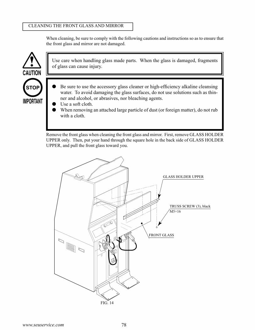
78www.seuservice.com 79 www.seuservice.com
When cleaning, be sure to comply with the following cautions and instructions so as to ensure that the front glass and mirror are not damaged.
Use care when handling glass made parts. When the glass is damaged, fragments of glass can cause injury.
Be sure to use the accessory glass cleaner or high-efficiency alkaline cleansing water. To avoid damaging the glass surfaces, do not use solutions such as thin-ner and alcohol, or abrasives, nor bleaching agents.
Use a soft cloth. When removing an attached large particle of dust (or foreign matter), do not rub
with a cloth.
FIG. 14
Remove the front glass when cleaning the front glass and mirror. First, remove GLASS HOLDER UPPER only. Then, put your hand through the square hole in the back side of GLASS HOLDER UPPER, and pull the front glass toward you.
CLEANING THE FRONT GLASS AND MIRROR
GLASS HOLDER UPPER
TRUSS SCREW (3), blackM5×16
FRONT GLASS
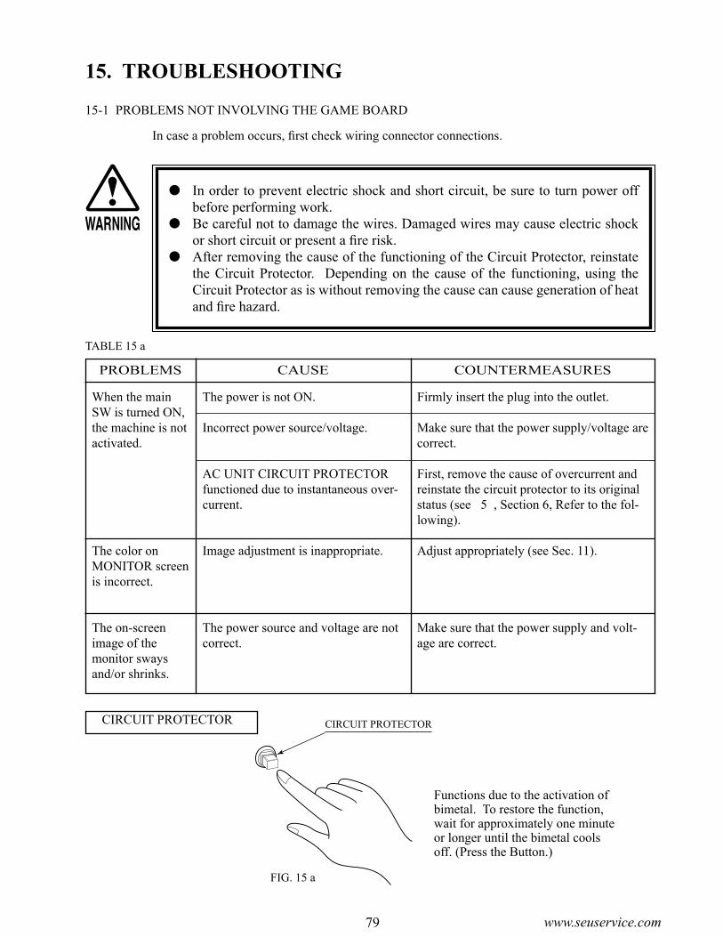
78www.seuservice.com 79 www.seuservice.com
FIG. 15 a
15. TROUBLESHOOTING
In case a problem occurs, first check wiring connector connections.
In order to prevent electric shock and short circuit, be sure to turn power off before performing work.
Be careful not to damage the wires. Damaged wires may cause electric shock or short circuit or present a fire risk.
After removing the cause of the functioning of the Circuit Protector, reinstate the Circuit Protector. Depending on the cause of the functioning, using the Circuit Protector as is without removing the cause can cause generation of heat and fire hazard.
CIRCUIT PROTECTOR
Functions due to the activation of bimetal. To restore the function, wait for approximately one minute or longer until the bimetal cools off. (Press the Button.)
CIRCUIT PROTECTOR
PROBLEMS CAUSE COUNTERMEASURES
When the main SW is turned ON, the machine is not activated.
The color on MONITOR screen is incorrect.
The on-screen image of the monitor sways and/or shrinks.
The power is not ON.
Incorrect power source/voltage.
AC UNIT CIRCUIT PROTECTOR functioned due to instantaneous over-current.
Image adjustment is inappropriate.
The power source and voltage are not correct.
Firmly insert the plug into the outlet.
Make sure that the power supply/voltage are correct.
First, remove the cause of overcurrent and reinstate the circuit protector to its original status (see 5 , Section 6, Refer to the fol-lowing).
Adjust appropriately (see Sec. 11).
Make sure that the power supply and volt-age are correct.
TABLE 15 a
15-1 PROBLEMS NOT INVOLVING THE GAME BOARD

80www.seuservice.com 81 www.seuservice.com
No sound is emitted.
Control Unit sighting is not satisfactory.
During game play, the Control Unit is not operable for shooting.
The weapon change button does not function properly.
The Fluorescent lamp does not light up.
The Lamp does not light up.
Sound volume adjustment is not ap-propriate.
Board and Amplifier malfunctioning.
Due to environmental changes, etc., sighting became inappropriate.
LED BD malfunctioning.
Sensor Unit malfunctioning.
LED BD, Front Glass, and Mirror are soiled.
Malfunctioning of microswitch.
Malfunctioning of LED BD.
Malfunctioning of Sensor Unit.
Microswitch malfunction.
The Fluorescent tube is burnt out.
Lamp malfunctioning.
Adjust sound volume (see Sec. 9).
Perform the sound test and confirm (see Sec. 9-2).
Perform sighting adjustment in the test mode (see Sec. 9).
Check to ensure that the LED lights up. If it does not light up, replace (see next page).
Replace the Sensor Unit (see Sec.10).
Wipe off soiled surfaces (see Sec. 14 and next page).
Check for ON and OFF in the INPUT test and if it is not functioning, replace the mi-croswitch (see Sec.10).
Check if the LED is lit, and if it is not lit, replace (see next page).
Replace the Sensor Unit.
Perform the input test to check that the but-ton switches ON and OFF properly. If the button is not functioning properly, replace the microswitch (see Sec. 10).
Replace the Fluorescent tube(see Sec. 13).
Replace the Lamp (see Sec. 13).
TABLE 15 b
PROBLEMS CAUSE COUNTERMEASURES

80www.seuservice.com 81 www.seuservice.com
FIG. 15 d
Turn the power off.
Remove the Back Door.
Disconnect the ASSY SENSOR CONNECTOR.
Unclamp the grounding cable. Remove the hexagon head nut, and remove a round grounding terminal from a screw shank.
Pull out the ASSY SENSOR.
Disconnect the connector from the both ends of the LED BD which shows defects.
Take out the 2 U Nuts to remove and replace the LED BD. At this time, pay attention to the direction of the LED BD, and install it.
After replacing the LED BD, be sure to perform sighting check according to the test mode of Section 9.
FIG. 15 b
FIG. 15 c
HEXAGON NUTM4, flat & springwashers used.
If the light emission of 2 LED's can not be seen, the fault or malfunctioning may be considered. Replace by using the following procedure. Also, when wiping off the soils, remove the ASSY SENSOR as per the same procedure.
If the light emission from the 2 LED's can not be seen, replace.
ASSY SENSOR
LED BD833-13145-02
U NUT (2)M3, plastic washer used.
REPLACING THE LED BD

82www.seuservice.com 83 www.seuservice.com
15-3 ERROR CODES
Chihiro displays error messages on the screen to indicate various problems.If an error message is displayed, the game cannot be started. In this case, refer to the following section on causes and countermeasures. In the text for this product below, "Media Board" and "DIMM" are one and the same.
Error 02[DISPLAY] Error 02 Main board malfunctioning.[CAUSE] MAIN BOARD is inoperative.[COUNTERMEASURES] Verify that the MAIN BOARD is connected properly.
Error 03[DISPLAY] Error 03 Bad serial number on main board.[CAUSE] Unable to read MAIN BOARD serial ID.[COUNTERMEASURES] Disconnect the MEDIA BOARD from the MAIN BOARD and
send the MAIN BOARD for repair.
Error 04[DISPLAY] Error 04 Bad serial number on media board.[CAUSE] Unable to read MEDIA BOARD serial ID.[COUNTERMEASURES] With the MEDIA BOARD still attached to the MAIN BOARD,
send the Chihiro for repair.
Error 05[DISPLAY] Error 05 This game is not acceptable by main board.[CAUSE] The game is a foreign edition.[COUNTERMEASURES] Use the domestic version of the game.
If an error code is displayed, have a Location's Maintenance Man or Service-man resolve it. If someone without specialized or technical knowledge attempts to rectify the problem, electric shock, short circuits or fire may result. If there is no store maintenance person or technician available, turn the power OFF im-mediately, and contact your retailer or the office listed in this manual.
If problems other than those noted in this manual occur, or the countermeasures suggested result in no improvement, do not try to rectify the problem by other means. Turn the power OFF immediately, and contact your retailer or the office listed in this manual. Careless countermeasures can result in unexpected acci-dents.
If error No. 20 is generated, the power must be turned OFF and ON again in order to clear it.
When requesting replacement or repair of the Game Board or Media Board, put the board in the special purpose packing box specified in this manual for transportation.

82www.seuservice.com 83 www.seuservice.com
Error 11[DISPLAY] Error 11 JVS I/O board is not connected to main board.[CAUSE] (1) I/O BOARD is not connected. (2)Unreliable connection between MAIN BOARD and I/O BOARD.[COUNTERMEASURES] (1)Connect the I/O BOARD to the MAIN BOARD. Verify that the power cable is connected to I/O BOARD. (2)Reconnect or replace the USB CABLE that connects the I/O BOARD to the MAIN BOARD.
Error 12[DISPLAY] Error 12 JVS I/O board does not fulfill the game spec.[CAUSE] Correct I/O BOARD is not connected.[COUNTERMEASURES] Use an I/O BOARD that provides the proper input/output for
the game.
Error 21[DISPLAY] Error 21 This game is not acceptable by main board.[CAUSE] Game data loaded from the GD-ROM to the DIMM BOARD is
corrupted.[COUNTERMEASURES] Verify the GD-ROM DRIVE and Chihiro connection. Check the GD-ROM disc for scratches, dust or dirt.
Error 22[DISPLAY] Error 22 Communication error occurred between main board and media
board.[CAUSE] No response from DIMM BOARD to MAIN BOARD.[COUNTERMEASURES] Ensure that the DIMM BOARD and the GD INTERFACE
BOARD are properly connected. Should the problem persist, the DIMM BOARD or GD
INTERFACE BOARD may be damaged.
Error 23[DISPLAY] Error 23 GD-ROM drive cover is open.[CAUSE] The GD-ROM DRIVE cover is open.[COUNTERMEASURES] Ensure the GD-ROM DRIVE cover is firmly closed.
Error 24[DISPLAY] Error 24 GD-ROM is not found.[CAUSE] GD-ROM disc is not found.[COUNTERMEASURES] Insert the GD-ROM disc correctly. Verify that the disc is a Chihiro GD-ROM disc. Check the GD-ROM disc for scratches, dust or dirt.

84www.seuservice.com 85 www.seuservice.com
Error 25[DISPLAY] Error 25 Cannot access GD-ROM drive.[CAUSE] (1)Unable to access GD-ROM DRIVE. (2)The GD-ROM DRIVE cover is open.[COUNTERMEASURES] (1)Verify that the GD CABLE and the power cable are properly connected to the GD-ROM DRIVE. (2)Close the GD-ROM cover securely. Should the problem persist, the GD-ROM DRIVE may be damaged.
Error 26[DISPLAY] Error 26 Media board malfunctioning.[CAUSE] KEY CHIP is not found.[COUNTERMEASURES] Attach the proper KEY CHIP for the game. Insert the KEY CHIP securely.
Error 27[DISPLAY] Error 27 DIMM memory is not enough.[CAUSE] (1) Insufficient DIMM MEMORY on DIMM BOARD. (2)DIMM MEMORY is not connected securely.[COUNTERMEASURES] (1)Provide a suitable amount of DIMM MEMORY for the software. (2)Verify that the DIMM MEMORY is connected securely to the DIMM BOARD.
Caution 51[DISPLAY] Caution 51 Wrong video output setting of horizontal scanning frequency.[CAUSE] The game does not support horizontal sync frequency setting.[COUNTERMEASURES] Change the No. 2�4 and 6�8 DIPSW correcty on the
CONNECTOR BOARD. The monitor must support these frequencies. (See "16-2 COMPOSITION OF GAME BOARD".)
Caution 52[DISPLAY] Caution 52 Wrong video output setting of horizontal/vertical screen.[CAUSE] The game does not support the vertical/horizontal screen
settings.[COUNTERMEASURES] Change the No. 1 DIPSW on the CONNECTOR BOARD. ON is for vertically placed monitor screens, OFF is for
horizontally placed monitor screens. Change the monitor placement from vertical to horizontal or vice
versa if necessary. (See "16-2 COMPOSITION OF GAME BOARD".)
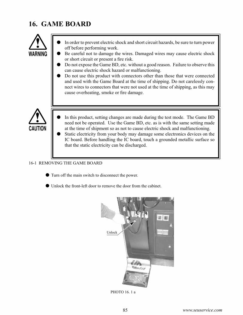
84www.seuservice.com 85 www.seuservice.com
PHOTO 16. 1 a
16. GAME BOARD
In order to prevent electric shock and short circuit hazards, be sure to turn power off before performing work.
Be careful not to damage the wires. Damaged wires may cause electric shock or short circuit or present a fire risk.
Do not expose the Game BD, etc. without a good reason. Failure to observe this can cause electric shock hazard or malfunctioning.
Do not use this product with connectors other than those that were connected and used with the Game Board at the time of shipping. Do not carelessly con-nect wires to connectors that were not used at the time of shipping, as this may cause overheating, smoke or fire damage.
In this product, setting changes are made during the test mode. The Game BD need not be operated. Use the Game BD, etc. as is with the same setting made at the time of shipment so as not to cause electric shock and malfunctioning.
Static electricity from your body may damage some electronics devices on the IC board. Before handling the IC board, touch a grounded metallic surface so that the static electricity can be discharged.
16-1 REMOVING THE GAME BOARD
Turn off the main switch to disconnect the power.
Unlock the front-left door to remove the door from the cabinet.
Unlock

86www.seuservice.com 87 www.seuservice.com
Take out the ASSY MAIN BD (with Chihiro board) from the cabinet. Remove the 8 connectors from the upper section of the rear of the door.
PHOTO 16. 1 b
Disconnect 1 connector from the lower section inside the door.
PHOTO 16. 1 c
Disconnect the connector.
Disconnect the connector.

86www.seuservice.com 87 www.seuservice.com
D-SUB CONNECTOR
Remove the 2 wing bolts that fix the ASSY MAIN BD's base (a wooden base).
PHOTO 16. 1 d
Pull the ASSY MAIN BD out about 30 cm from the Cabinet. Be careful not to damage the wiring at this time.
Unplug the D-SUB connector from the side of the Game Board on the ASSY MAIN BD.
PHOTO 16. 1 e
PHOTO 16. 1 f
WING BOLT (2)M4×30, flat washer used

88www.seuservice.com 89 www.seuservice.com
Unplug all connectors connected to the Chihiro Board. Unplug the GD Cable connector on the side of the Media Board on the Chihiro Board.
Unplug the AVIP Cable connected to the Chihiro Board. Because the AVIP Cable is packed with it when the Chihiro Board is transported, unfasten the cord clamp that fastens the cable and remove it.
Pull the ASSY MAIN BD out of the Cabinet and set it on a level surface before continuing with the following procedure.
PHOTO 16. 1 g
PHOTO 16. 1 h
PHOTO 16. 1 i
Unplug all connectors.
AVIP CABLE

88www.seuservice.com 89 www.seuservice.com
Remove the 4 screws and remove the Chihiro Board from the Base.
PHOTO 16. 1 j
SCREW (4)M4×16, w/flat & spring washers
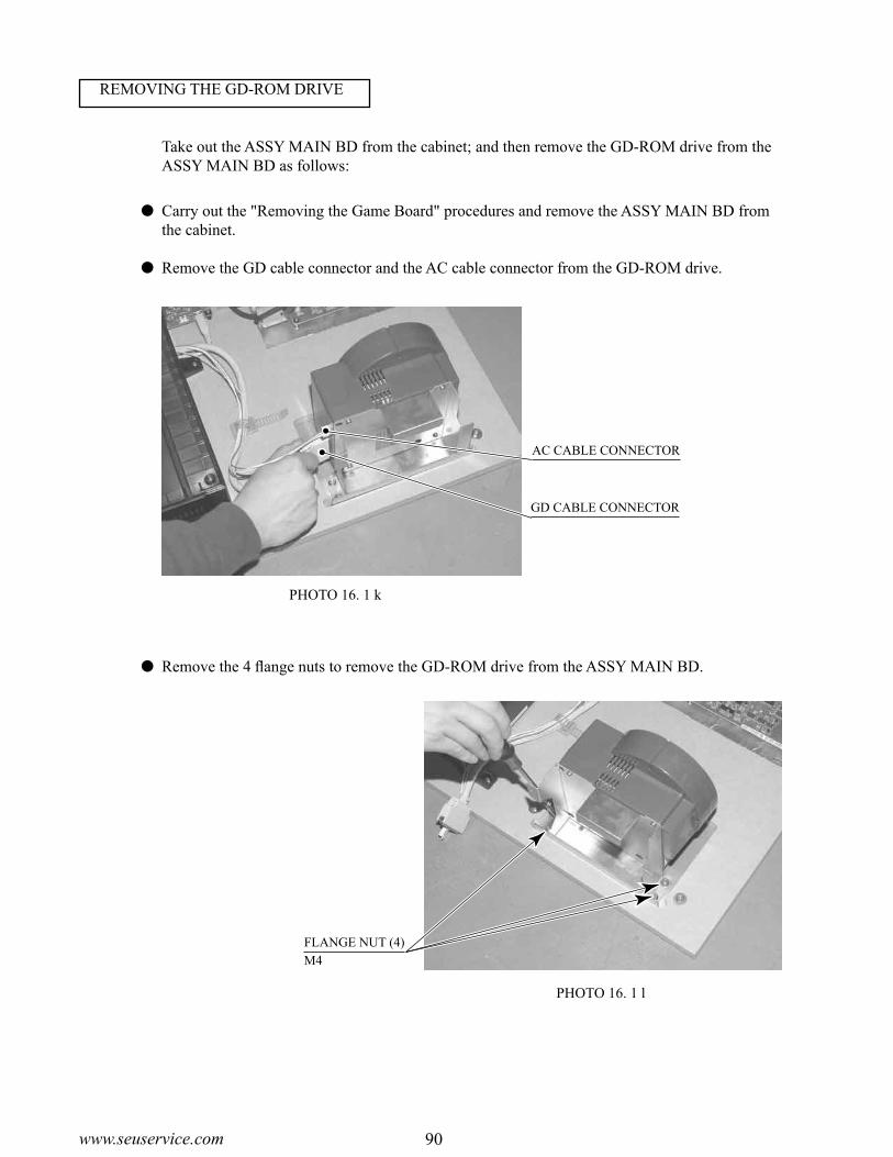
90www.seuservice.com 91 www.seuservice.com
Carry out the "Removing the Game Board" procedures and remove the ASSY MAIN BD from the cabinet.
Remove the GD cable connector and the AC cable connector from the GD-ROM drive.
PHOTO 16. 1 k
Take out the ASSY MAIN BD from the cabinet; and then remove the GD-ROM drive from the ASSY MAIN BD as follows:
Remove the 4 flange nuts to remove the GD-ROM drive from the ASSY MAIN BD.
PHOTO 16. 1 l
GD CABLE CONNECTOR
AC CABLE CONNECTOR
FLANGE NUT (4)M4
REMOVING THE GD-ROM DRIVE

90www.seuservice.com 91 www.seuservice.com
16-2 COMPOSITION OF THE GAME BOARD
FIG. 16. 2 b
Use this product with the DIP SW settings shown in the figure below.
DIP SW SETTING
Once the Chihiro Board has the Key Chip inserted, it is this product's specialized Game Board.
FIG. 16. 2 a
ASSY CASE BOX VCT EXP(843-0003D-02)
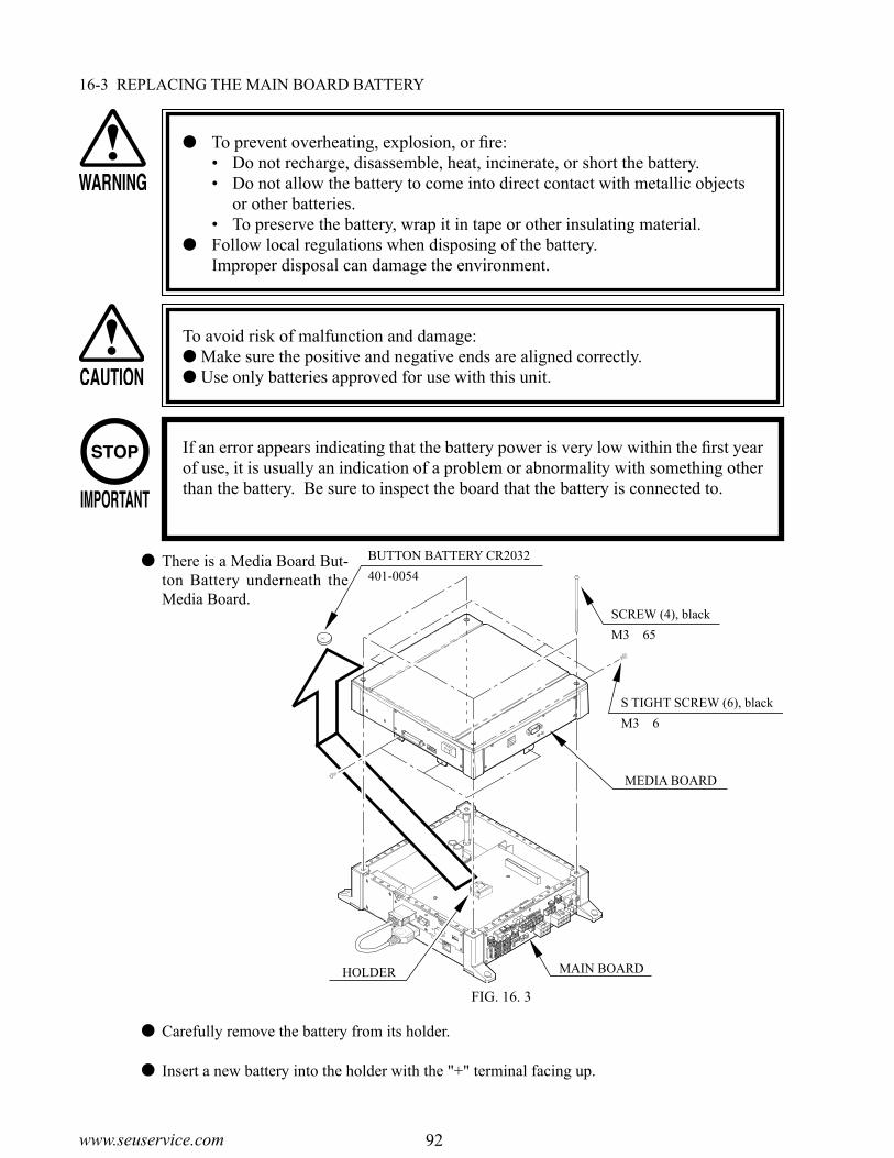
92www.seuservice.com 93 www.seuservice.com
MEDIA BOARD
MAIN BOARDHOLDER
SCREW (4), black
M3×65
S TIGHT SCREW (6), black
M3×6
BUTTON BATTERY CR2032
401-0054
16-3 REPLACING THE MAIN BOARD BATTERY
To prevent overheating, explosion, or fire:• Do not recharge, disassemble, heat, incinerate, or short the battery.• Do not allow the battery to come into direct contact with metallic objects
or other batteries.• To preserve the battery, wrap it in tape or other insulating material.
Follow local regulations when disposing of the battery. Improper disposal can damage the environment.
To avoid risk of malfunction and damage: Make sure the positive and negative ends are aligned correctly. Use only batteries approved for use with this unit.
If an error appears indicating that the battery power is very low within the first year of use, it is usually an indication of a problem or abnormality with something other than the battery. Be sure to inspect the board that the battery is connected to.
There is a Media Board But-ton Battery underneath the Media Board.
FIG. 16. 3
Carefully remove the battery from its holder.
Insert a new battery into the holder with the "+" terminal facing up.

92www.seuservice.com 93 www.seuservice.com
16-4 REPLACING THE MEDIA BOARD BATTERY PACK
Do not disassemble the battery pack and the batteries. If you should fail to observe this instruction, the internal wires and/or
protective devices may be damaged; as a result the safety system may not function when discharging and recharging, eventually causing an overheating, fire and explosion. If you should disassemble the batteries, the generated gases may harm your throat and the negative plate may overheat and make a fire.
Do not make an external short circuit of the battery pack and the batteries. If you should fail to observe this instruction, the batteries may overheat, make
a fire, and explode. Do not fire the battery pack and the batteries. If you should fail to observe this instruction, the batteries may make a fire and
explode. Do not leave the battery pack and the batteries nearby the heat source (fire or
heater) or under the intense direct sunlight and flaming sun. If you should fail to observe this instruction, the batteries may reduce the service life and in the worst case may overheat, make a fire, and explode.
Do not leave the battery pack and the batteries in water or seawater. Also do not apply water or seawater onto the battery pack and the batteries. If you should fail to observe this instruction, the internal wires and/or protective devices may be damaged; as a result the safety system may not function when discharging and recharging, eventually causing an overheating, fire and explosion. Also water may be electrolyzed into oxygen and hydrogen, and eventually the battery's sealed section may be corroded and the internal liquid may leak.
Do not solder on the battery pack's terminals. If you should fail to observe this instruction, the armor may be heated
and melted or the internal wires may be damaged, eventually causing an overheating, fire and explosion. Also, when the battery's temperature reaches to 100º or more, the battery may leak its internal liquid due to destruction of its plastic parts (gasket, separator, etc.), or may overheat, make a fire, or explode due to internal short-circuit.
Do not insert or connect the battery in a reversal polarity. If you should fail to observe this instruction, the battery may be externally
short-circuited and eventually overheat, make a fire, or explode, depending on the device you connect with.
Be careful when handling the battery pack.We bear no responsibility for problems caused by handling clearly contrary to the content of this manual.
Prohibitions and Cautions to Handle the Battery Pack

94www.seuservice.com 95 www.seuservice.com
Do not tightly seal the battery pack when installing it onto an external device. Flammable gas is generated from the battery when its safety mechanism has
functioned. If you should fail to observe the above-described instruction, sparks from motors, switches, etc. may cause the gas to fire. Therefore, install the battery pack so that the gas can be quickly released from the external device.
Do not use the battery pack for the device/usage other than this game system. If you should fail to observe this instruction, the battery and/or the device may
be damaged due to non-applicable specifications. Do not strike a nail in, hammer, step on, or apply any other forms of pressures
and shocks on, the battery. If you should fail to observe this instruction, the battery may be deformed. As
a result, the battery may burst at its sealed sections to leak the internal liquid, or may be short-circuited internally to overheat, make a fire, and explode.
Do not use a battery charger because any battery charger is not usable for this battery pack.
If you should fail to observe this instruction, the gas may be suddenly generated in the battery and eventually the battery may overheat, make a fire or explode.
If the battery in use or in keeping shows an abnormal indication (deformation, change of color, bursting of the armor cover, etc.), immediately stop using or keeping it. If it leaks and smells abnormally, immediately keep it away from fire and put it in a safety box.
If the liquid leaks from the battery and gets in your eyes, do not rub your eyes but immediately wash them with clean water (city water etc.); and consult a medical doctor for a treatment. If you should fail to observe this instruction, the liquid may harm your eyes.
The battery pack armor (a polyvinyl chloride tube) may be damaged or deformed by external force or heat. When transporting the battery pack or replacing it with a new one, therefore, be careful not to drop or excessively shock it. Do not continue to use any damaged or deformed battery pack. If you should fail to observe this instruction, the battery may overheat, make a fore, or explode.
The battery pack contains a printed circuit board (PCB) for protective circuitry. It may be destroyed by the static electricity. When handling or servicing the battery pack, therefore, take preventive measures against the static electricity.
If your battery pack has shown destruction of a protective circuitry PCB, do not continue to use it. If you should fail to observe this instruction, the battery may overheat, make a fore, or explode.
When wiring the battery pack to a device, be careful not to apply excessive force onto the connectors and lead wires. The battery may overheat, make a fire, or explode if the connectors and lead wires are damaged.
Do not do away with the used battery packs carelessly because they may contaminate the environment. Be sure to dispose of the used battery packs in accordance with the laws/regulations of your country.

94www.seuservice.com 95 www.seuservice.com
SCREW (4), black
M3×65
TAPPING SCREW (1), black
3×8
MEDIA BOARD
BATTERY PACK
401-0081
COVER BATTERY HOLDER
CONNECTOR
TOP COVER
FIG. 16. 4
If the GD-ROM read time becomes excessively long, it is likely that the Media Board battery pack life if running low.No battery pack charger is available.Follow the procedure to replace the battery pack.
Remove 4 screws from the upper face of the board.
Remove the top cover.
Remove 1 tapping screw and remove the cover battery holder.
Disconnect the connector at the end of the wire coming out of the battery pack. Remove by pressing the projection on the connector and pulling.
Securely connect the new battery pack.
Attach the cover battery holder and top cover.
Submit the used battery packs to an industrial waste disposal plant. Thus they must be disposed according to the local laws and the regulations in your country.

96www.seuservice.com 97 www.seuservice.com
17. DESIGN RELATED PARTS
5
67
8
4
3
2
1
ITEM NO. PART NO. DESCRIPTION NOTE
1 999-1777 Pop Art VCT 2 999-1607 Decal Start Button 3 999-1783 Control Panel Instructions VCT 4 999-1782 Decal Control Panel Right VCT 5 999-1781 Decal Control Panel Left VCT 6 999-1779 Decal Monitor Side Left VCT 7 999-1780 Decal Monitor Side Right VCT 8 999-1778 Marquee VCT 9 999-1430 Label Epilepsy Warning SEGA
9

96www.seuservice.com 97 www.seuservice.com
18. PARTS LIST 1 TOP ASSY VCT U/R D-1/2
56
4
3
2
1

98www.seuservice.com
1 TOP ASSY VCT U/R D-2/2
ITEM NO. PART NO. DESCRIPTION NOTE
1 Local Purchase 24 in Coolwhite Fluorescent Bulb 2 Local Purchase Monitor Glass 3 Local Purchase Speaker 8Ohm 15 Watt 4 VCT-1250 Assy Foot Pedal 5 601-9377 Caster 160-2 1/2 #251888 Swivel 6 601-5699X Leg Adjuster Bolt M16X75
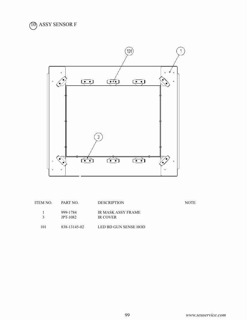
99 www.seuservice.com
10 ASSY SENSOR F
ITEM NO. PART NO. DESCRIPTION NOTE
1 999-1784 IR MASK ASSY FRAME 3 JPT-1082 IR COVER
101 838-13145-02 LED BD GUN SENSE HOD

100www.seuservice.com 101 www.seuservice.com
13 ASSY CTRL PNL U/R D-1/2

100www.seuservice.com 101 www.seuservice.com
13 ASSY CTRL PNL U/R D-2/2
ITEM NO. PART NO. DESCRIPTION NOTE
1 VCT1-2201 CTRL PNL BASE 2 999-1786 SPEAKER HOLDER MINI 5 VCT1-1103 HOLDER 6 999-1781 DESIGN SHEET CTRL PNL VCT L 7 999-1782 DESIGN SHEET CTRL PNL VCT R 8 VCT1-2204 HOLDER BRKT UR 9 VCT1-2205 HOLDER BRKT STAND 10 999-1785 PROTECT SHEET

102www.seuservice.com 103 www.seuservice.com
14 CONTROL UNIT EXP (VCT-2100-01) D-1/2
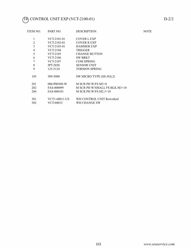
102www.seuservice.com 103 www.seuservice.com
14 CONTROL UNIT EXP (VCT-2100-01) D-2/2
ITEM NO. PART NO. DESCRIPTION NOTE
1 VCT-2101-01 COVER L EXP 2 VCT-2102-01 COVER R EXP 3 VCT-2103-01 HAMMER EXP 4 VCT-2104 TRIGGER 5 VCT-2105 CHANGE BUTTON 6 VCT-2106 SW BRKT 7 VCT-2107 COM SPRING 8 JPT-2030 SENSOR UNIT 9 125-5124 TORSION SPRING
103 509-5080 SW MICRO TYPE (SS-5GL2) 201 000-P00308-W M SCR PH W/FS M3×8 202 FAS-000099 M SCR PH W/SMALL FS BLK M3×10 204 FAS-000101 M SCR PH W/FS M2.3×10
301 VCT1-60011-US WH CONTROL UNIT Reworked 302 VCT-60012 WH CHANGE SW

104www.seuservice.com 105 www.seuservice.com
15 SENSOR UNIT (JPT-2030)
ITEM NO. PART NO. DESCRIPTION NOTE
1 JPT-2031 SENSOR HOLDER
101 838-13144 SENSOR BD GUN SENSE
201 012-P00306 TAP SCR #2 PH 3X6

104www.seuservice.com 105 www.seuservice.com
16 ASSY MAIN BD U/R (VCT-4200) D-1/2
5
4
3
21
ITEM NO. PART NO. DESCRIPTION NOTE
1 837-13551-92 IO Control BD For JVS 2 XKT-0833 Kit GD-ROM Drive W/Label 3 610-0674 Power Protect Unit for Chihiro 4 400-5443 Power Supply 5 843-0001D-11 Assy Case Box COM NAO

106www.seuservice.com 107 www.seuservice.com
16 ASSY MAIN BD U/R (VCT-4200) D-2/2
5
4
3
2
ITEM NO. PART NO. DESCRIPTION NOTE
2 838-13616 Audio Power Amp 2CH 3 998-0190 Transformer Audio A41-130-36 4 998-0165 PCB - Gun Protect BD Type II 5 838-13143-09 IC BD Gun Sense SPY

106www.seuservice.com 107 www.seuservice.com
19 ASSY FOOT BASE U/R
ITEM NO. PART NO. DESCRIPTION NOTE
1 VCT-1351 FOOT BASE FRAME U/R Metric Threading
101 280-5275-SR10 CORD CLAMP SR10
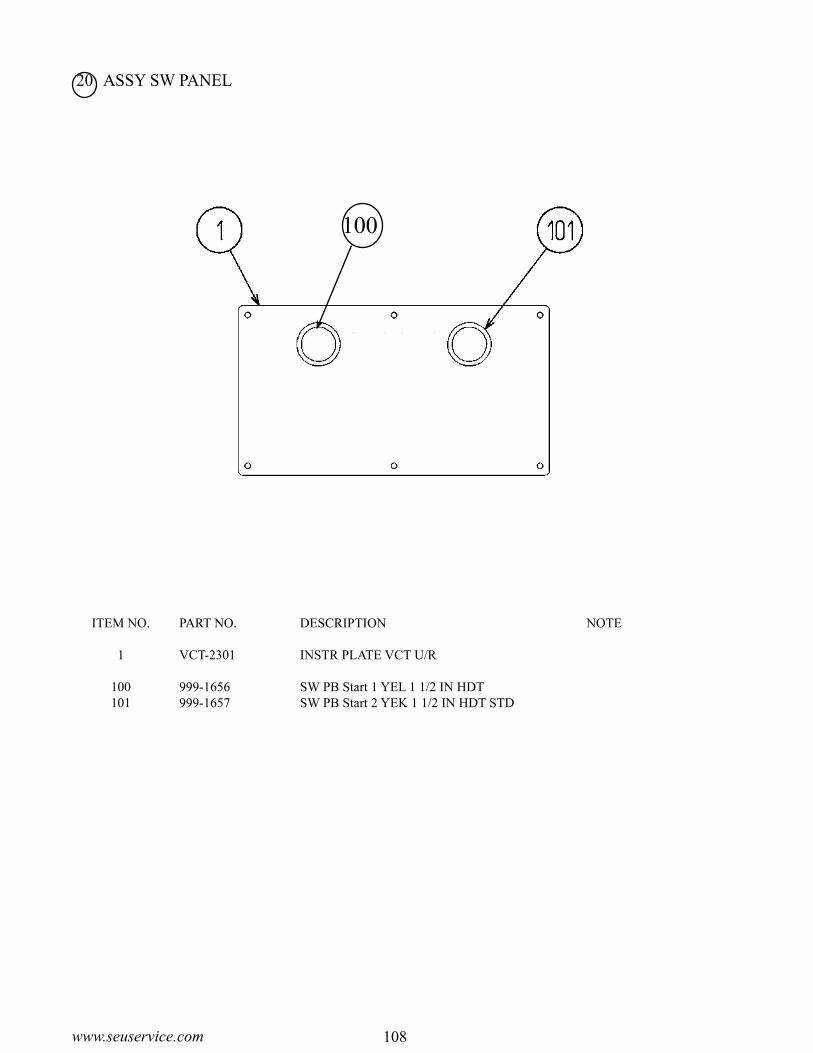
108www.seuservice.com 109 www.seuservice.com
20 ASSY SW PANEL
ITEM NO. PART NO. DESCRIPTION NOTE
1 VCT-2301 INSTR PLATE VCT U/R
100 999-1656 SW PB Start 1 YEL 1 1/2 IN HDT 101 999-1657 SW PB Start 2 YEK 1 1/2 IN HDT STD
100

108www.seuservice.com 109 www.seuservice.com
18 ASSY FOOT PEDAL U/R (VCT-1250) D-1/2
Det
ails
NO
TE
: A
pply
gre
ase
to th
e sp
ring
por
tions
.
G
RE
ASE
: 09
0-02
79
G
RE
ASE
AL
BA
NIA
S2
400G

110www.seuservice.com 111 www.seuservice.com
18 ASSY FOOT PEDAL U/R (VCT-1250) D-2/2
ITEM NO. PART NO. DESCRIPTION NOTE
1 VCT-1251X PEDAL BASE U/R 2 VCT-1202X PEDAL 3 VCT-1203 FOOT PLATE 4 VCT-1204 COM SPRING 5 VCT-1205 SPRING COVER 6 VCT-1206 SHADE PLATE 7 VCT-1207 SENSOR BRKT 8 VCT-1208 WIRE COVER 9 VCT-1209 STOPPER RUBBER 10 VCT-1210 RUBBER CUSHION 11 VCT-1211 RUBBER CASE 12 VCT-1212 CUSHION 13 VCT-1252 PEDAL BASE LID 14 VCT-1253 STICKER FOOT PEDAL U/R
101 370-5226 PHOTO SENSOR OMT-01DAMP NEW 102 280-6622-30030 SPACER TUBE 103 280-5275-SR10 CORD CLAMP SR10
201 FAS-000102 M SCR TH BLK M5×6 202 FAS-290034 HEX SKT LH CAP SCR STN M5×15 203 000-F00512 M SCR FH M5×12 204 000-P00310-W M SCR PH W/FS M3×10 205 050-F00400 FLG NUT M4 206 000-P00408-WB M SCR PH W/FS BLK M4×8
301 VCT-61003 WH PEDAL

110www.seuservice.com 111 www.seuservice.com
19. WIRE COLOR CODE TABLETHE WIRE COLOR CODE is as follow:
A PINK
B SKY BLUE
C BROWN
D PURPLE
E LIGHT GREEN
Wires other than those of any of the above 5 single colors will be displayed by 2
alphanumeric characters.
1 RED
2 BLUE
3 YELLOW
4 GREEN
5 WHITE
7 ORANGE
8 BLACK
9 GRAY
If the right-hand side numeral of the code is 0, then the wire will be of a single color shown
by the left-hand side numeral (see the above).
Note 1: If the right-hand side alphanumeric is not 0, that particular wire has a spiral color
code. The left-hand side character shows the base color and the right-hand side
one, the spiral color.
<Example> 51 ……… WHITE / RED
Note 2: The character following the wire color code indicates the size of the wire.
U: AWG16
K: AWG18
L: AWG20
None: AWG22
RED WHITE

112www.seuservice.com
NOTES:

Warranty
Your new Sega Product is covered for a period of 90 days from the date of shipment. This certifies that the Printed Circuit Boards, Power Supplies and Monitor are to be free of defects in workman-ship or materials under normal operating conditions. This also certifies that all Interactive Control Assemblies are to be free from defects in workmanship and materials under normal operating condi-tions. No other product in this machine is hereby covered.
Sellers sole liability in the event a warranted part described above fails shall be, at its option, to re-place or repair the defective part during the warranty period. For Warranty claims, contact your Sega Distributor.
Should the Seller determine, by inspection that the product was caused by Accident, Misuse, Ne-glect, Alteration, Improper Repair, Installation or Testing, the warranty offered will be null and void.
Under no circumstances is the Seller responsible for any loss of profits, loss of use, or other dam-ages.
This shall be the exclusive written Warranty of the original purchaser expressed in lieu of all other warranties expressed or implied. Under no circumstance shall it extend beyond the period of time listed above.

SEGA AMUSEMENTS USA, INC.