Uprating Semiconductors for High-Temperature Applications - Micron
14
TN-00-18: Temperature Uprating on Semiconductors Introduction PDF: 09005aef81694133/Source: 09005aef8169415f Micron Technology, Inc., reserves the right to change products or specifications without notice. TN0018.fm - Rev. F 5/10 EN 1 ©2004 Micron Technology, Inc. All rights reserved. Products and specifications discussed herein are for evaluation and reference purposes only and are subject to change by Micron without notice. Products are only warranted by Micron to meet Micron’s production data sheet specifications. All information discussed herein is provided on an “as is” basis, without warranties of any kind. Technical Note Uprating Semiconductors for High-Temperature Applications Introduction Uprating is used to evaluate a part’s ability to function and perform when it is used outside of the manufacturer’s specified temperature range. 21 For example, the maximum junction temperature of Micron’s DDR SDRAM is 95°C. Before including a DDR SDRAM in an application operating above that temperature, a customer would use the process of uprating to determine the related risks. Uprating is possible because semiconductor manufacturers’ design significant margin into their products to increase device yield and reliability. This technical note describes the issues associated with temperature uprating and the risks involved in using components outside the manufacturers’ environmental specifi- cations. Through its commercial off-the-shelf (COTS) program, the U.S. Department of Defense has been uprating for a number of years. There are three major concerns with this practice: 1. Device functionality and performance—including AC and DC timings, refresh, and speed of the part 2. Device reliability, or the reliability of the thin-film MOS device 3. Package reliability, including concerns with wire bonds and solder joints This note focuses specifically on temperature uprating and the significant failure mech- anisms associated with operating semiconductors outside their specified temperature ranges. The failure mechanisms apply to all MOS and bipolar semiconductor products, whether manufactured by Micron or any other semiconductor company. Device Functionality Micron ® semiconductor devices go through a series of functional tests under elevated temperatures to ensure device performance. The junction temperature specifications listed in Table 1 on page 2 are derived directly from these tests. Table 2 shows the industry-standard temperature definitions for CMOS-based devices. If these tempera- tures are exceeded, the data sheet specifications for speed, refresh, and timings cannot be guaranteed. As with all semiconductor devices, increasing temperatures adversely affects device functionality, quality, and reliability. Even though all Micron devices have significant margin designed and tested in, Micron cannot guarantee the data sheet spec- ified performance of any device pushed past its tested limits.
Transcript of Uprating Semiconductors for High-Temperature Applications - Micron

TN-00-18 Temperature Uprating on SemiconductorsIntroduction
Technical NoteUprating Semiconductors for High-Temperature Applications
IntroductionUprating is used to evaluate a partrsquos ability to function and perform when it is used outside of the manufacturerrsquos specified temperature range21 For example the maximum junction temperature of Micronrsquos DDR SDRAM is 95degC Before including a DDR SDRAM in an application operating above that temperature a customer would use the process of uprating to determine the related risks Uprating is possible because semiconductor manufacturersrsquo design significant margin into their products to increase device yield and reliability
This technical note describes the issues associated with temperature uprating and the risks involved in using components outside the manufacturersrsquo environmental specifi-cations Through its commercial off-the-shelf (COTS) program the US Department of Defense has been uprating for a number of years There are three major concerns with this practice1 Device functionality and performancemdashincluding AC and DC timings refresh and
speed of the part2 Device reliability or the reliability of the thin-film MOS device 3 Package reliability including concerns with wire bonds and solder joints
This note focuses specifically on temperature uprating and the significant failure mech-anisms associated with operating semiconductors outside their specified temperature ranges The failure mechanisms apply to all MOS and bipolar semiconductor products whether manufactured by Micron or any other semiconductor company
Device FunctionalityMicronreg semiconductor devices go through a series of functional tests under elevated temperatures to ensure device performance The junction temperature specifications listed in Table 1 on page 2 are derived directly from these tests Table 2 shows the industry-standard temperature definitions for CMOS-based devices If these tempera-tures are exceeded the data sheet specifications for speed refresh and timings cannot be guaranteed As with all semiconductor devices increasing temperatures adversely affects device functionality quality and reliability Even though all Micron devices have significant margin designed and tested in Micron cannot guarantee the data sheet spec-ified performance of any device pushed past its tested limits
PDF 09005aef81694133Source 09005aef8169415f Micron Technology Inc reserves the right to change products or specifications without noticeTN0018fm - Rev F 510 EN 1 copy2004 Micron Technology Inc All rights reserved
Products and specifications discussed herein are for evaluation and reference purposes only and are subject to change by Micron without notice Products are only warranted by Micron to meet Micronrsquos production data sheet specifications All
information discussed herein is provided on an ldquoas isrdquo basis without warranties of any kind
TN-00-18 Temperature Uprating on SemiconductorsDevice Functionality
Notes 1 Refresh rate is device dependant refer to data sheets2 Requires 32ms refresh to operate above 90degC
Table 1 Junction Temperature Functionality
Device Application
Temperature (degC)
Min Max
DRAM SDRAM DDR SDRAM Commercial 0 85
Industrial ndash40 95
Automotive1 ndash40 110
Mobile SDRAM Mobile DDR SDRAM Mobile DDR2 SDRAM
Commercial 0 85
Industrial ndash40 95
Automotive1 ndash40 110
MCPAIO Commercial 0 90
Industrial ndash40 90
emiddotMMCtrade Wireless ndash30 90
Industrial ndash40 90
Flash Commercial 0 90
Wireless ndash30 90
Industrial ndash40 90
DDR2 SDRAM Commercial2 0 90
Industrial2 ndash40 100
Automotive2 ndash40 110
DDR3 SDRAM Commercial2 0 100
Industrial2 ndash40 100
Automotive2 ndash40 110
PSRAM Wireless1 ndash30 95
Industrial1 ndash40 95
Automotive1 ndash40 110
RLDRAMreg Commercial 0 100
Industrial ndash40 100
Table 2 Industry-Standard Typical Junction Temperature Limits
Application
Temperature (degC)
Min Max
Commercial 0 70
Industrial ndash40 95
AutomotiveGrade 2 ndash40 105Grade 1 ndash40 125
Military(example of one range)
ndash65 125
PDF 09005aef81694133Source 09005aef8169415f Micron Technology Inc reserves the right to change products or specifications without noticeTN0018fm - Rev F 510 EN 2 copy2004 Micron Technology Inc All rights reserved
TN-00-18 Temperature Uprating on SemiconductorsDevice Reliability
Device ReliabilityWhen determining the risk associated with operating at extended temperatures a few factors must be consideredbull What is the real reliability target of the end systembull What is the useful life of the end system (For example if the end system is a GPS
navigation system for a car how long does the unit need to last)bull How many hours a day will the unit be powered throughout its life
If you assume 2 hours of use a day across a 20-year life the DRAM only has to last 14560 hours or about 17 years of continuous use assuming only 1 DRAM per system The values determined in the failure in time per billion device hours (FIT) rate calculations only apply when there is power to the device In most cases the functional life of the end system is far shorter than that of the DRAM primarily because the reliability standards that govern the DRAM industry are based on applications that use 32 or more devices per system such as servers The number of devices in the system and their effects on reliability are detailed in ldquoFailure Rate Calculationrdquo on page 5
Figure 1 Reliability Curve
The long-term reliability and failure rates for CMOS devices is typically described in the form of a curve depicting the life of the IC This reliability curve is known as a bathtub curve due to its shape (see Figure 1) The curve shows the failure rate of a population of ICs over time A small percentage of devices will have inherent manufacturing defects after the devices have passed all electrical testing and are functional at time = 0 Manu-facturing defects caused by contamination and process variation lead to a shorter life in comparison to the remaining population These defects are referred to as ldquoinfant mortalityrdquo Infant mortality makes up only a small percentage of the total population but is the largest percentage of early life failures in ICs
DRAM devices are subjected to 125degC at elevated voltages (burn-in) to remove the infant mortality part of the population prior to shipping After the devices in the infant mortality section of the bathtub curve are removed from the population the remaining part of the population displays a stable field failure rate Micron uses an intelligent burn-inmdashthe parts are operated during the stress condition to show the exact time of failure Following the infant mortality section there is a relatively flat portion of the bathtub curve that represents the useful life of the IC where you would expect to see a very low field failure rate The random field failures experienced during the useful life of the IC will eventually be replaced with an exponential failure rate This is shown in the wear out section of the bathtub curve The time frame and random field failures in the useful life of the IC can be predicted using statistics based on lab data from a sample of parts and will vary greatly depending on the operating temperature the IC This process is explained in detail in the following pages
Hazard Rate h(t)
Infantmortality Wear out
Mean time between failures (MTBF)applies in this range
Random failures
Time
Useful life
PDF 09005aef81694133Source 09005aef8169415f Micron Technology Inc reserves the right to change products or specifications without noticeTN0018fm - Rev F 510 EN 3 copy2004 Micron Technology Inc All rights reserved
TN-00-18 Temperature Uprating on SemiconductorsLong-Term Reliability
Long-Term Reliability Statistically predicting the long-term reliability of a DRAM requires test conditions that accelerate the stress on the device to screen out those with defects while at the same time not damaging the remaining portion of the population Both temperature and voltage are used as acceleration factors during testing Accelerated temperature and voltages are not set to a point that would damage the device thereby causing a failure that would not occur under normal operating conditions During high temperature operating life testing the devices are subjected to 125degC at an internal voltage of VCC + 04V Afterward extrapolation from accelerated conditions to nominal conditions is possible
Temperature Acceleration FactorThe Arrhenius equation shown in Equation 1 is used to statistically predict and model the accelerations factor due to temperature
Arrhenius Equation (EQ 1)
k = Boltzmannrsquos constant = 8617 times 10ndash5eVKTO = Operating temperature in kelvinsTS = Stress temperature in kelvinsEA = Activation energy for respective failure mechanism
The stress temperature (TS) used to collect data is 125degC TO is the normalized operating temperature All temperature data is converted into degrees kelvin Boltzmannrsquos constant illustrated as k in the Arrhenius equation is equal to 8617 times 10ndash5eVK The activation energy (EA) expressed in electron volts (eV) is a function of the temperature dependence on the failure mechanism The lower the EA the less influence the tempera-ture has on the failure mechanism EA is derived through experimental stress data collected at burn-in over time that is common among all semiconductor devices In the case of DRAM the most relevant activation energy is due to the time dependent dielec-tric breakdown (TDDB) When TO is equal to TS the acceleration factor due to tempera-ture is equal to 1 As seen by the Arrhenius equation temperature has an exponential effect on the long-term reliability of all CMOS-based ICs
AFT eEA
k------ 1
To------ 1
Ts------ndashlang rang
=
PDF 09005aef81694133Source 09005aef8169415f Micron Technology Inc reserves the right to change products or specifications without noticeTN0018fm - Rev F 510 EN 4 copy2004 Micron Technology Inc All rights reserved
TN-00-18 Temperature Uprating on SemiconductorsOverall Acceleration Factor
Voltage Acceleration Factor
The second acceleration factor used in long-term reliability testing is voltage The voltage acceleration factor is shown in Equation 2 Voltage stress is independent of the operating voltage specified in the data sheet in most cases Most DRAM devices inter-nally regulate the voltage down to an internal operating voltage VCC of the given process During the high-temperature operating life test and burn-in the regulators are disabled with the voltage moved to VCC + 04V as a stress voltage The constant (β) is determined experimentally in relation to TDDB representing the slope in relation to the time between a failure versus the stress voltage β is primarily dependent on the thick-ness of the gate oxide used in the manufacturing process As shown by this model voltage is also exponentially related to the reliability of CMOS devices
Voltage Acceleration Factor (EQ 2)
β = Constant the value is derived experimentallyVS = Stress voltageVO = Operating voltage
Overall Acceleration FactorThe overall acceleration factor (AFOA) is calculated as the product of the two respective acceleration factors (temperature and voltage) The AFOA shows the relationship from the stress conditions using unregulated voltages to nominal conditions as seen in the system AFOA is shown in Equation 3
Overall Acceleration Factor (EQ 3)
Failure Rate CalculationThe failure rate of an IC can be expressed in many different ways but once you have the data it is not difficult to convert the data into the desired format Assuming that failures occur as random independent events component failure rates can be calculated using Equation 4 The three components used to predict the final failure rate are Poisson statistic device hours tested and the number of failures in the sample size being tested
Failure Rate Calculation (EQ 4)
The Poisson statistic used in this equation Pn is derived from the Poisson probability distribution equation shown in Equation 5 Pr in the equations below represents 1 minus the confidence level at which the failure rate is calculated In the equation r represents the total number of fails in the sample size After Pr and r are defined you can solve for Pn Calculating the Poisson statistic can be difficult without a statistics calculator but the values used in the Poisson curves can be estimated as seen in Figure 2 on page 6 C represents the number of fails in the sample size and Pa represents 1 minus the confi-dence level Drawing a horizontal line from the Pa value until it intersects the curve C
AFV eβ Vs Vondashlang rang=
AFOA AFV AFTtimes=
AFOA relative to typicalsystem operating
conditionstimesDevice hours at
accelerated environment
PnFailurerate =
PDF 09005aef81694133Source 09005aef8169415f Micron Technology Inc reserves the right to change products or specifications without noticeTN0018fm - Rev F 510 EN 5 copy2004 Micron Technology Inc All rights reserved
TN-00-18 Temperature Uprating on SemiconductorsFailure Rate Calculation
equals the Poisson statistic The Pn value can then be determined by dropping a vertical line down from the intersection The confidence levels of 60 and 90 are shown based on zero fails in the sample size Table 3 on page 7 is provided to show the Poisson statistic based on the number of fails vs the confidence levels set at 60 and 90 from 0 to 5 failures Micron uses a 60 confidence level for all failure rate calculations published for DRAM devices If a higher level of confidence is needed recalculating this can be done using a different Pn to represent the desired confidence level
Poisson Probability Distribution Equation (EQ 5)
Pr = One minus the confidence level at which the failure rate is calculatedr = The total number of failed devices from our test samples
Figure 2 Poisson Curves
Notes 1 C = Acceptable number of failures in the sample
Pr
rΣ
i 0== e PnPnrndash( )
i( )------------------------------
999990
99990
9990
100
990
100000
10000
1000
10
20
90
807060504030
05
04
03
02
51
01
3218060402010 030201987654
03 20510198765=C 0504
4 = C
3 = C
2 = C
1 = C
0 = C
Pn
Pa60 confidence
90 confidence
091
6
230
3
PDF 09005aef81694133Source 09005aef8169415f Micron Technology Inc reserves the right to change products or specifications without noticeTN0018fm - Rev F 510 EN 6 copy2004 Micron Technology Inc All rights reserved
TN-00-18 Temperature Uprating on SemiconductorsApplying the Reliability Data to System Use Conditions
The total device hours tested under the stress conditions is relatively straightforward For this part of the equation the total number of devices is multiplied by the total amount of time in the high temperature operating test The total number of fails obvi-ously affects the final reliability calculation but so does the time of the fail Early failures have a greater affect on the final result than to fails later in the test flow This is because early failures reduce the total number of device test hours more than failures that happen later in the test flow For example if the sample size is 100 throughout the testing and each device is tested for 1008 hours then the total device hours equates to 100 times 1008 or 100800 hours of device operation
The final element of the failure rate calculation is the overall acceleration facture due to temperature and voltage as discussed earlier This acceleration factor is where the temperature can be varied to determine the failure rate based on a nominal voltage and temperature
After the failure rate is calculated it can be expressed in two formats failures per billion device hours (FIT) or the percentage of failures per thousand device hours To convert the failure rate calculation into a FIT rate the value needs to be multiplied by 10+9 and to convert this into a percent failures per thousand device hours the value is multiplied by 10+5 The failure rate at Micron is expressed in failures per billion device hours FIT
To determine the total system FIT rate the calculated FIT rate for a given IC is multiplied by the number of DRAM devices in the system For example if the FIT rate for a single component is 10 a system using 4 DRAM devices would have a total system FIT rate of 40 FIT As mentioned earlier this is the reason that the number of DRAM used in the system is crucial to the overall system reliability
Applying the Reliability Data to System Use ConditionsWith the reliability statistics laid out in the previous pages predicting the system FIT rate at a given confidence level is relatively straightforward FIT can be calculated by replacing the TO value in the temperature acceleration factor with the sustained oper-ating temperature of the system along with the number of devices Deriving the mean time between failure (MTBF) from the system FIT can be done using Equation 6 where n is the number of components in the system The units for MTBF calculation are hours of use
Mean Time Between Failure (EQ 6)
Table 3 Poisson Statistic
Number of Fails 60 Confidence Level 90 Confidence Level
0 0916 23031 2022 38902 3105 53223 4175 66814 5237 79945 6291 9275
MTBF 1n FITs 10 9ndashtimestimes--------------------------------------=
PDF 09005aef81694133Source 09005aef8169415f Micron Technology Inc reserves the right to change products or specifications without noticeTN0018fm - Rev F 510 EN 7 copy2004 Micron Technology Inc All rights reserved
TN-00-18 Temperature Uprating on SemiconductorsApplying the Reliability Data to System Use Conditions
System FIT Rate Example
Equation 7 is an example of the system FIT rate for a 256Mb SDRAM device for an appli-cation running at 105degC
System FIT Rate for a 256Mb SDRAM (EQ 7)
k = Boltzmannrsquos constant = 8617 times 10ndash5eVKTO = Operating temperature in kelvinsTS = Stress temperature in kelvinsEA = Activation energy for respective failure mechanismβ = Constant the value is derived experimentallyVS = Stress voltageVO = Operating voltage
Table 4 illustrates the high-temperature operating life data collected for the 256Mb SDRAM device This data is necessary when calculating the total hours tested and the number of failures in the sample size
The device hours is a simple calculation of the number of devices multiplied by the total number of hours tested measured in hours
Device hours=(1496 - 168) + (1496 - 168) + (1496 - 168) + (600 - 168) +(600 - 168) + (600 - 168) = 1056384 or 1056 times 10+6
The Poisson statistic is calculated using a single fail in the sample size at a 60 confi-dence level as seen in Equation 8
Poisson Statistic Calculated at a 60 Confidence Level (EQ 8)
Table 4 256Mb SDRAM Example Test Data
Sample 168 Hours 336 Hours 504 Hours 672 Hours 840 Hours 1008 Hours
1 0498 0498 0498 0200 0200 02002 0499 0499 1499 0200 0200 02003 0499 0499 0499 0200 0200 0200
Total 01496 01496 11496 00600 00600 00600Failure Analysis Summary
Interval Sample No of Fails504 hours 2 1
AFT e
068617 5ndashtimes10--------------------------- 1
378--------- 1
398---------ndash⎝ ⎠
⎛ ⎞
2524= =
AFV e5 27 23ndash( ) 7389= =
AFOV 7389 2524times 18650= =
041Σ
i 0== e Pnndash Pn1( )
i( )-------------------------
P n( ) 2022=
PDF 09005aef81694133Source 09005aef8169415f Micron Technology Inc reserves the right to change products or specifications without noticeTN0018fm - Rev F 510 EN 8 copy2004 Micron Technology Inc All rights reserved
TN-00-18 Temperature Uprating on SemiconductorsApplying the Reliability Data to System Use Conditions
The final failure rate and FIT can now be calculated for the operating temperature of 105degC
Final Failure and FIT Rates (EQ 9)
FR = failure rate
With the FIT rate calculated the MTBF can be calculated In Equation 10 we are assuming one device in the system See Figure 3
Mean Time Between Failure Calculation (EQ 10)
Figure 3 Example of Memory System Mean Time Between Failure for Micron Multiple 256Mb SDRAM Components
FR 20221056 106times 18650times---------------------------------------------------=
FR 1027 10 7ndashtimes=
FR 1027 10 7ndashtimes 10 109 102=timestimes=
MTBF 1 1 times 102 times 10ndash9
98 million hours
1100 years
--------------------- =
MTBF ~ ~
MTBF ~ ~
50
60
70
80
90
100
110
120
0 50 100 150 200 250 300 350 400 450 500
MTBF (Years)
Tem
per
atu
re deg
C
4 Parts8 Parts16 Parts32 Parts
PDF 09005aef81694133Source 09005aef8169415f Micron Technology Inc reserves the right to change products or specifications without noticeTN0018fm - Rev F 510 EN 9 copy2004 Micron Technology Inc All rights reserved
TN-00-18 Temperature Uprating on SemiconductorsPackage Reliability
Package ReliabilityPackage reliability is generally not a concern at constant operating temperatures below 125degC However reliability predictions can be made if conditions in the use environment are known and acceleration factors are calculated Data provided by Micron in device qualification reports or acquired by applying knowledge of expected failure mechanisms in the use environment can be used to calculate the acceleration factors
The Hallberg-Peck acceleration model is commonly used for temperature and humidity stress
Hallberg-Peck (EQ 11)
WhereEA = Activation energy of defect mechanism (09 commonly used)Boltzmannrsquos constant (k) = 86174 times 10ndash5 eVKRHs = Stress test environment relative humidityRHo = Operating use environment relative humidityTs = Stress test environment temperature To = Operating use environment temperature
Two common acceleration models are used to calculate thermal cycling stress
Coffin-Manson (EQ 12)
Modified Coffin-Manson (SnPb solder joints) (EQ 13)
Wherem = Exponent dependent on defect mechanism and material ΔTs = Stress test thermal cycle temperature change ΔTo = Operating use thermal cycle temperature changeFo = Operating use thermal cycling frequencyFs = Stress test thermal cycling frequencyTs = Maximum temperature during stress test thermal cycleTo = Maximum temperature during operating use thermal cycle
SummaryWhen exceeding the specified device temperature limits the customer faces three concerns First the functionality and performance of the device must be considered and the system design must be adjusted accordingly Second device reliability is reduced which can be calculated using the proper reliability equations Finally temper-atures below +125degC are not a concern for package reliability but temperature cycling can be a concern and should be avoided
AFRHsRHo----------⎝ ⎠⎛ ⎞
3etimes
EAk
------⎝ ⎠⎛ ⎞ 1
To----- 1
Ts-----ndash⎝ ⎠
⎛ ⎞times=
AFΔTsΔTo---------⎝ ⎠⎛ ⎞
m=
AFΔTsΔTo---------⎝ ⎠⎛ ⎞ 19˜ Fo
Fs------⎝ ⎠⎛ ⎞
1 3frasle
001 Ts Tondash( )times[ ]timestimes=
PDF 09005aef81694133Source 09005aef8169415f Micron Technology Inc reserves the right to change products or specifications without noticeTN0018fm - Rev F 510 EN 10 copy2004 Micron Technology Inc All rights reserved
TN-00-18 Temperature Uprating on SemiconductorsSummary
Uprating can be performed on many levels The military for instance through its COTS program buys commercially-rated semiconductors and re-evaluates device suitability for its temperature-rated applications This can be accomplished using a variety of methods including common practices of parameter conformance parameter recharac-terization stress balancing and higher assembly level testing13 However these processes are very expensive and add to the cost of the components18
At the other extreme the user could simply take commercially rated devices assess their critical function parameters and decreased reliability and simply design the system around these issues
Many semiconductor manufacturers design significant margin into their products However semiconductor manufacturers who provide products for multiple temperature specification ranges as Micron does generally do not have different device fabrication processes based on the expected temperature range of the application For example commercial and industrial devices are generally from the same fabrication process and therefore have equivalent intrinsic device reliability The primary difference is that the industrial devices have been screened for data sheet functionality at the necessary temperature extremes13
Before products are uprated a thorough understanding of the thermal environment is needed Uprating can be an expensive process If devices are never subjected to extended temperatures there is probably no reason to add the costs associated with uprating even if the system has been specified to extended temperatures For details on thermal measurements see Micronrsquos Thermal Application Technical Note TN-00-08
PDF 09005aef81694133Source 09005aef8169415f Micron Technology Inc reserves the right to change products or specifications without noticeTN0018fm - Rev F 510 EN 11 copy2004 Micron Technology Inc All rights reserved
TN-00-18 Temperature Uprating on SemiconductorsReferences
References
Book References1 Harman G and Harper CA Wire Bonding in Microelectronics Materials Processes
Reliability and Yield 2nd Ed McGraw-Hill New York 1997 2 Kirschman R High-Temperature Electronics IEEE Press New York 19993 Lall P Precht M G and Hakim E B Influence of Temperature on Microelectronics
CRC Press Boca Raton 1997 4 McCluskey F P Grzybowski R and Podlesak T High-Temperature Electronics CRC
Press Boca Raton 1997 5 Amerasekera E Ajith Najm Farid N Failure Mechanisms in Semiconductor Devices
2nd Ed John Wiley amp Sons Hoboken 1998
Paper References6 Barker D ldquoRuggedizing Laptop Computers for Mobile Applicationsrdquo Presented at the
first workshop on use of components outside specified temperature limits CALCE EPRC University of Maryland College Park January 23 1997
7 Biddle S ldquoBeyond Quality ndash Assuring the Reliability of Plastic Encapsulated Inte-grated Circuitsrdquo COTS Journal March 2003
8 Condra L Das D Pendse N and Pecht M ldquoJunction Temperature Considerations in Evaluating Electronic Parts for Use Outside Manufacturers-Specified Temperature Rangesrdquo IEEE Trans Comp Pack Tech Vol 24 pp 721ndash728 December 2001
9 Das D Pendse N Pecht M and Wilkinson C ldquoDeciphering the Deluge of Datardquo Circuits and Devices September 2000
10 Das D Pendse N Pecht M and Wilkinson C ldquoParameter Recharacterization A Method of Thermal Upratingrdquo IEEE Trans Comp Pack Tech Vol 24 pp 729ndash737 December 2001
11 Dasgupta A et al ldquoDoes the Cooling of Electronics Increase Reliabilityrdquo Presented at the Proc Thermal Stresses 95 Conference No 231 1995
12 Davila-Rieth K ldquoUprating Assemblies for Military Computer Systemsrdquo Presented at the first workshop on use of components outside specified temperature limits CALCE EPRC University of Maryland College Park January 23 1997
13 Humphrey D et al ldquoAn Avionics Guide to Uprating of Electronic Partsrdquo IEEE Trans Comp Pack Tech Vol 23 pp 595ndash599 September 2000
14 Kroger R ldquoManufacturer Part Assessment A Pragmatic Approachrdquo Presented at the first workshop on use of components outside specified temperature limits CALCE EPRC University of Maryland College Park January 23 1997
15 Lall P et al ldquoCharacterization of Functional Relationship Between Temperature and Microelectronic Reliabilityrdquo Microelecton Vol 35 No 3 pp 377ndash402 March 1995
16 McCluskey P et al ldquoUprating of Commercial Parts for Use in Harsh Environmentsrdquo CALCE EPRC Rep November 1996
17 Ng K K ldquoA Survey of Semiconductor Devicesrdquo IEEE Trans Electron Devices Vol 43 pp 1760ndash1766 October 1996
18 Pecht M ldquoIssues Affecting Early Affordable Access to Leading Electronics Technolo-gies by the US Military and Governmentrdquo Circuit World Vol 22 No 2 pp 7ndash15 1996
19 Pendse N Thomas D Das D and Precht M ldquoUprating of a Single Inline Memory Modulerdquo IEEE Trans Comp Pack Tech Vol 25 No 2 pp 266ndash269 June 2002
PDF 09005aef81694133Source 09005aef8169415f Micron Technology Inc reserves the right to change products or specifications without noticeTN0018fm - Rev F 510 EN 12 copy2004 Micron Technology Inc All rights reserved
TN-00-18 Temperature Uprating on SemiconductorsReferences
20 Suhir E ldquoAccelerated Life Testing (ALT) in Microelectronics and Photonics Its Role Attributes Challenges Pitfalls and Interaction With Qualification Testsrdquo Journal of Electronic Packaging Vol124 pp 281ndash290 September 2002
21 Wright M et al ldquoUprating Electronic Components for use Outside their Tempera-ture Specification Limitsrdquo IEEE Trans Comp Packaging and Manufacturing Tech-nology-Part A Vol 20 pp 252ndash256 June 1997
Micron References22 Quality and Reliability Handbook23 256Mb Qualification Document24 A Gallo Fink J ldquoReliability of Commercial Plastic Encapsulated Microelectronics at
Temperatures from +125degC to +300degCrdquo Dexter Technical Paper July 1999
8000 S Federal Way PO Box 6 Boise ID 83707-0006 Tel 208-368-3900wwwmicroncomproductsupport Customer Comment Line 800-932-4992
Micron and the Micron logo are trademarks of Micron Technology Ince-MMCtrade is a trademark of the JEDEC Solid State Technology Association RLDRAM is a registered trademark of Qimonda AG in various
countries and is used by Micron Technology Inc under license from QimondaAll other trademarks are the property of their respective owners
PDF 09005aef81694133Source 09005aef8169415f Micron Technology Inc reserves the right to change products or specifications without noticeTN0018fm - Rev F 510 EN 13 copy2004 Micron Technology Inc All rights reserved
TN-00-18 Temperature Uprating on SemiconductorsRevision History
Revision HistoryRev F 510
bull Updated Table 1 ldquoJunction Temperature Functionalityrdquo on page 2
Rev E 508bull Updated Table 1 ldquoJunction Temperature Functionalityrdquo on page 2
Rev D 107bull Updated Table 1 ldquoJunction Temperature Functionalityrdquo on page 2bull Edited for readabilitybull Corrected Table 2 ldquoIndustry-Standard Typical Junction Temperature Limitsrdquo on
page 2 Under the hood temperature to -40-150
Rev C 1106bull Updated ldquoDevice Reliabilityrdquo sectionbull Added ldquoLong-Term Reliabilityrdquo ldquoTemperature Acceleration Factorrdquo ldquoOverall Acceler-
ation Factorrdquo ldquoFailure Rate Calculationrdquo and ldquoApplying the Reliability Data to System Use Conditionsrdquo sections
Rev B 1105bull Updated templatebull Corrected typos Equation 2 on page 2 TN-00-08 reference on page 10 and Boltz-
mannrsquos constant from 86171 to 86174 on page 10
Rev A 1004bull Initial release
PDF 09005aef81694133Source 09005aef8169415f Micron Technology Inc reserves the right to change products or specifications without noticeTN0018fm - Rev F 510 EN 14 copy2004 Micron Technology Inc All rights reserved
- Introduction
- Device Functionality
- Device Reliability
- Long-Term Reliability
- Temperature Acceleration Factor
-
- Voltage Acceleration Factor
-
- Overall Acceleration Factor
- Failure Rate Calculation
- Applying the Reliability Data to System Use Conditions
-
- System FIT Rate Example
-
- Package Reliability
- Summary
- References
-
- Book References
- Paper References
- Micron References
-
- Revision History
-
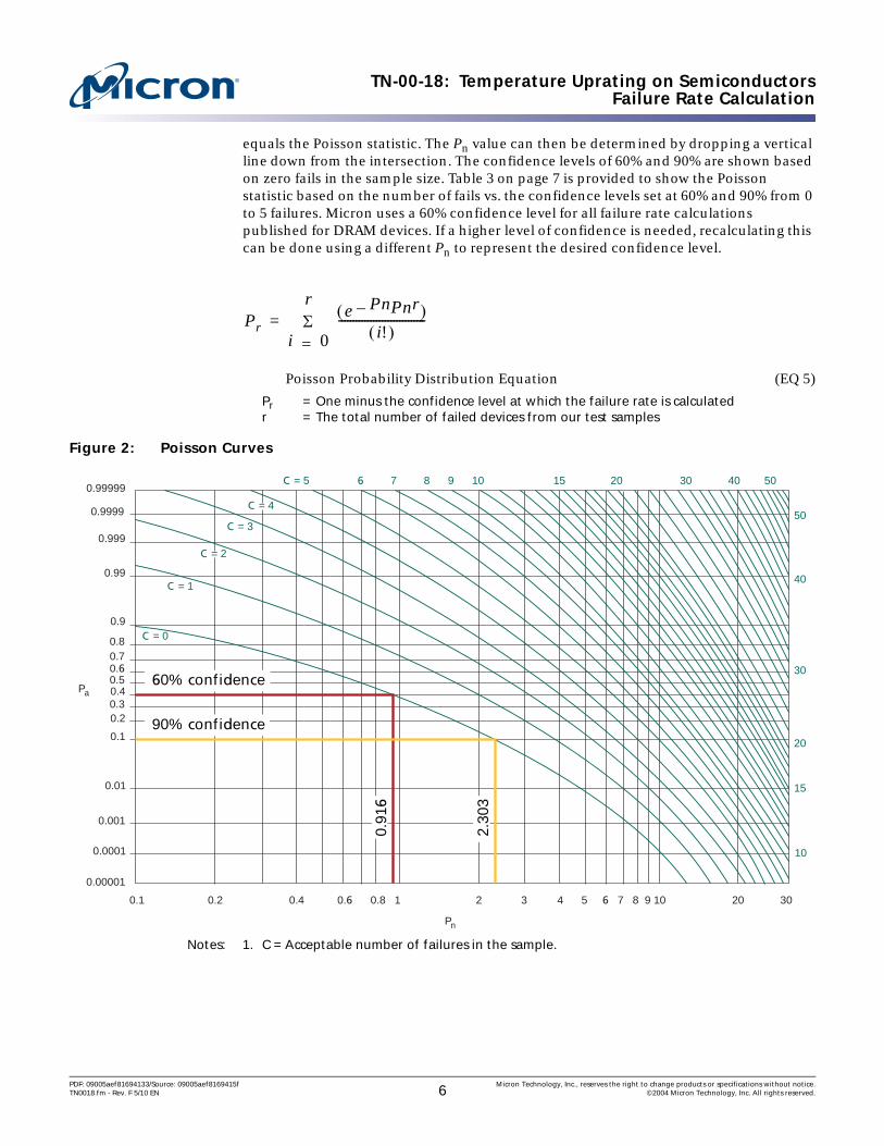

TN-00-18 Temperature Uprating on SemiconductorsApplying the Reliability Data to System Use Conditions
System FIT Rate Example
Equation 7 is an example of the system FIT rate for a 256Mb SDRAM device for an appli-cation running at 105degC
System FIT Rate for a 256Mb SDRAM (EQ 7)
k = Boltzmannrsquos constant = 8617 times 10ndash5eVKTO = Operating temperature in kelvinsTS = Stress temperature in kelvinsEA = Activation energy for respective failure mechanismβ = Constant the value is derived experimentallyVS = Stress voltageVO = Operating voltage
Table 4 illustrates the high-temperature operating life data collected for the 256Mb SDRAM device This data is necessary when calculating the total hours tested and the number of failures in the sample size
The device hours is a simple calculation of the number of devices multiplied by the total number of hours tested measured in hours
Device hours=(1496 - 168) + (1496 - 168) + (1496 - 168) + (600 - 168) +(600 - 168) + (600 - 168) = 1056384 or 1056 times 10+6
The Poisson statistic is calculated using a single fail in the sample size at a 60 confi-dence level as seen in Equation 8
Poisson Statistic Calculated at a 60 Confidence Level (EQ 8)
Table 4 256Mb SDRAM Example Test Data
Sample 168 Hours 336 Hours 504 Hours 672 Hours 840 Hours 1008 Hours
1 0498 0498 0498 0200 0200 02002 0499 0499 1499 0200 0200 02003 0499 0499 0499 0200 0200 0200
Total 01496 01496 11496 00600 00600 00600Failure Analysis Summary
Interval Sample No of Fails504 hours 2 1
AFT e
068617 5ndashtimes10--------------------------- 1
378--------- 1
398---------ndash⎝ ⎠
⎛ ⎞
2524= =
AFV e5 27 23ndash( ) 7389= =
AFOV 7389 2524times 18650= =
041Σ
i 0== e Pnndash Pn1( )
i( )-------------------------
P n( ) 2022=
PDF 09005aef81694133Source 09005aef8169415f Micron Technology Inc reserves the right to change products or specifications without noticeTN0018fm - Rev F 510 EN 8 copy2004 Micron Technology Inc All rights reserved
TN-00-18 Temperature Uprating on SemiconductorsApplying the Reliability Data to System Use Conditions
The final failure rate and FIT can now be calculated for the operating temperature of 105degC
Final Failure and FIT Rates (EQ 9)
FR = failure rate
With the FIT rate calculated the MTBF can be calculated In Equation 10 we are assuming one device in the system See Figure 3
Mean Time Between Failure Calculation (EQ 10)
Figure 3 Example of Memory System Mean Time Between Failure for Micron Multiple 256Mb SDRAM Components
FR 20221056 106times 18650times---------------------------------------------------=
FR 1027 10 7ndashtimes=
FR 1027 10 7ndashtimes 10 109 102=timestimes=
MTBF 1 1 times 102 times 10ndash9
98 million hours
1100 years
--------------------- =
MTBF ~ ~
MTBF ~ ~
50
60
70
80
90
100
110
120
0 50 100 150 200 250 300 350 400 450 500
MTBF (Years)
Tem
per
atu
re deg
C
4 Parts8 Parts16 Parts32 Parts
PDF 09005aef81694133Source 09005aef8169415f Micron Technology Inc reserves the right to change products or specifications without noticeTN0018fm - Rev F 510 EN 9 copy2004 Micron Technology Inc All rights reserved
TN-00-18 Temperature Uprating on SemiconductorsPackage Reliability
Package ReliabilityPackage reliability is generally not a concern at constant operating temperatures below 125degC However reliability predictions can be made if conditions in the use environment are known and acceleration factors are calculated Data provided by Micron in device qualification reports or acquired by applying knowledge of expected failure mechanisms in the use environment can be used to calculate the acceleration factors
The Hallberg-Peck acceleration model is commonly used for temperature and humidity stress
Hallberg-Peck (EQ 11)
WhereEA = Activation energy of defect mechanism (09 commonly used)Boltzmannrsquos constant (k) = 86174 times 10ndash5 eVKRHs = Stress test environment relative humidityRHo = Operating use environment relative humidityTs = Stress test environment temperature To = Operating use environment temperature
Two common acceleration models are used to calculate thermal cycling stress
Coffin-Manson (EQ 12)
Modified Coffin-Manson (SnPb solder joints) (EQ 13)
Wherem = Exponent dependent on defect mechanism and material ΔTs = Stress test thermal cycle temperature change ΔTo = Operating use thermal cycle temperature changeFo = Operating use thermal cycling frequencyFs = Stress test thermal cycling frequencyTs = Maximum temperature during stress test thermal cycleTo = Maximum temperature during operating use thermal cycle
SummaryWhen exceeding the specified device temperature limits the customer faces three concerns First the functionality and performance of the device must be considered and the system design must be adjusted accordingly Second device reliability is reduced which can be calculated using the proper reliability equations Finally temper-atures below +125degC are not a concern for package reliability but temperature cycling can be a concern and should be avoided
AFRHsRHo----------⎝ ⎠⎛ ⎞
3etimes
EAk
------⎝ ⎠⎛ ⎞ 1
To----- 1
Ts-----ndash⎝ ⎠
⎛ ⎞times=
AFΔTsΔTo---------⎝ ⎠⎛ ⎞
m=
AFΔTsΔTo---------⎝ ⎠⎛ ⎞ 19˜ Fo
Fs------⎝ ⎠⎛ ⎞
1 3frasle
001 Ts Tondash( )times[ ]timestimes=
PDF 09005aef81694133Source 09005aef8169415f Micron Technology Inc reserves the right to change products or specifications without noticeTN0018fm - Rev F 510 EN 10 copy2004 Micron Technology Inc All rights reserved
TN-00-18 Temperature Uprating on SemiconductorsSummary
Uprating can be performed on many levels The military for instance through its COTS program buys commercially-rated semiconductors and re-evaluates device suitability for its temperature-rated applications This can be accomplished using a variety of methods including common practices of parameter conformance parameter recharac-terization stress balancing and higher assembly level testing13 However these processes are very expensive and add to the cost of the components18
At the other extreme the user could simply take commercially rated devices assess their critical function parameters and decreased reliability and simply design the system around these issues
Many semiconductor manufacturers design significant margin into their products However semiconductor manufacturers who provide products for multiple temperature specification ranges as Micron does generally do not have different device fabrication processes based on the expected temperature range of the application For example commercial and industrial devices are generally from the same fabrication process and therefore have equivalent intrinsic device reliability The primary difference is that the industrial devices have been screened for data sheet functionality at the necessary temperature extremes13
Before products are uprated a thorough understanding of the thermal environment is needed Uprating can be an expensive process If devices are never subjected to extended temperatures there is probably no reason to add the costs associated with uprating even if the system has been specified to extended temperatures For details on thermal measurements see Micronrsquos Thermal Application Technical Note TN-00-08
PDF 09005aef81694133Source 09005aef8169415f Micron Technology Inc reserves the right to change products or specifications without noticeTN0018fm - Rev F 510 EN 11 copy2004 Micron Technology Inc All rights reserved
TN-00-18 Temperature Uprating on SemiconductorsReferences
References
Book References1 Harman G and Harper CA Wire Bonding in Microelectronics Materials Processes
Reliability and Yield 2nd Ed McGraw-Hill New York 1997 2 Kirschman R High-Temperature Electronics IEEE Press New York 19993 Lall P Precht M G and Hakim E B Influence of Temperature on Microelectronics
CRC Press Boca Raton 1997 4 McCluskey F P Grzybowski R and Podlesak T High-Temperature Electronics CRC
Press Boca Raton 1997 5 Amerasekera E Ajith Najm Farid N Failure Mechanisms in Semiconductor Devices
2nd Ed John Wiley amp Sons Hoboken 1998
Paper References6 Barker D ldquoRuggedizing Laptop Computers for Mobile Applicationsrdquo Presented at the
first workshop on use of components outside specified temperature limits CALCE EPRC University of Maryland College Park January 23 1997
7 Biddle S ldquoBeyond Quality ndash Assuring the Reliability of Plastic Encapsulated Inte-grated Circuitsrdquo COTS Journal March 2003
8 Condra L Das D Pendse N and Pecht M ldquoJunction Temperature Considerations in Evaluating Electronic Parts for Use Outside Manufacturers-Specified Temperature Rangesrdquo IEEE Trans Comp Pack Tech Vol 24 pp 721ndash728 December 2001
9 Das D Pendse N Pecht M and Wilkinson C ldquoDeciphering the Deluge of Datardquo Circuits and Devices September 2000
10 Das D Pendse N Pecht M and Wilkinson C ldquoParameter Recharacterization A Method of Thermal Upratingrdquo IEEE Trans Comp Pack Tech Vol 24 pp 729ndash737 December 2001
11 Dasgupta A et al ldquoDoes the Cooling of Electronics Increase Reliabilityrdquo Presented at the Proc Thermal Stresses 95 Conference No 231 1995
12 Davila-Rieth K ldquoUprating Assemblies for Military Computer Systemsrdquo Presented at the first workshop on use of components outside specified temperature limits CALCE EPRC University of Maryland College Park January 23 1997
13 Humphrey D et al ldquoAn Avionics Guide to Uprating of Electronic Partsrdquo IEEE Trans Comp Pack Tech Vol 23 pp 595ndash599 September 2000
14 Kroger R ldquoManufacturer Part Assessment A Pragmatic Approachrdquo Presented at the first workshop on use of components outside specified temperature limits CALCE EPRC University of Maryland College Park January 23 1997
15 Lall P et al ldquoCharacterization of Functional Relationship Between Temperature and Microelectronic Reliabilityrdquo Microelecton Vol 35 No 3 pp 377ndash402 March 1995
16 McCluskey P et al ldquoUprating of Commercial Parts for Use in Harsh Environmentsrdquo CALCE EPRC Rep November 1996
17 Ng K K ldquoA Survey of Semiconductor Devicesrdquo IEEE Trans Electron Devices Vol 43 pp 1760ndash1766 October 1996
18 Pecht M ldquoIssues Affecting Early Affordable Access to Leading Electronics Technolo-gies by the US Military and Governmentrdquo Circuit World Vol 22 No 2 pp 7ndash15 1996
19 Pendse N Thomas D Das D and Precht M ldquoUprating of a Single Inline Memory Modulerdquo IEEE Trans Comp Pack Tech Vol 25 No 2 pp 266ndash269 June 2002
PDF 09005aef81694133Source 09005aef8169415f Micron Technology Inc reserves the right to change products or specifications without noticeTN0018fm - Rev F 510 EN 12 copy2004 Micron Technology Inc All rights reserved
TN-00-18 Temperature Uprating on SemiconductorsReferences
20 Suhir E ldquoAccelerated Life Testing (ALT) in Microelectronics and Photonics Its Role Attributes Challenges Pitfalls and Interaction With Qualification Testsrdquo Journal of Electronic Packaging Vol124 pp 281ndash290 September 2002
21 Wright M et al ldquoUprating Electronic Components for use Outside their Tempera-ture Specification Limitsrdquo IEEE Trans Comp Packaging and Manufacturing Tech-nology-Part A Vol 20 pp 252ndash256 June 1997
Micron References22 Quality and Reliability Handbook23 256Mb Qualification Document24 A Gallo Fink J ldquoReliability of Commercial Plastic Encapsulated Microelectronics at
Temperatures from +125degC to +300degCrdquo Dexter Technical Paper July 1999
8000 S Federal Way PO Box 6 Boise ID 83707-0006 Tel 208-368-3900wwwmicroncomproductsupport Customer Comment Line 800-932-4992
Micron and the Micron logo are trademarks of Micron Technology Ince-MMCtrade is a trademark of the JEDEC Solid State Technology Association RLDRAM is a registered trademark of Qimonda AG in various
countries and is used by Micron Technology Inc under license from QimondaAll other trademarks are the property of their respective owners
PDF 09005aef81694133Source 09005aef8169415f Micron Technology Inc reserves the right to change products or specifications without noticeTN0018fm - Rev F 510 EN 13 copy2004 Micron Technology Inc All rights reserved
TN-00-18 Temperature Uprating on SemiconductorsRevision History
Revision HistoryRev F 510
bull Updated Table 1 ldquoJunction Temperature Functionalityrdquo on page 2
Rev E 508bull Updated Table 1 ldquoJunction Temperature Functionalityrdquo on page 2
Rev D 107bull Updated Table 1 ldquoJunction Temperature Functionalityrdquo on page 2bull Edited for readabilitybull Corrected Table 2 ldquoIndustry-Standard Typical Junction Temperature Limitsrdquo on
page 2 Under the hood temperature to -40-150
Rev C 1106bull Updated ldquoDevice Reliabilityrdquo sectionbull Added ldquoLong-Term Reliabilityrdquo ldquoTemperature Acceleration Factorrdquo ldquoOverall Acceler-
ation Factorrdquo ldquoFailure Rate Calculationrdquo and ldquoApplying the Reliability Data to System Use Conditionsrdquo sections
Rev B 1105bull Updated templatebull Corrected typos Equation 2 on page 2 TN-00-08 reference on page 10 and Boltz-
mannrsquos constant from 86171 to 86174 on page 10
Rev A 1004bull Initial release
PDF 09005aef81694133Source 09005aef8169415f Micron Technology Inc reserves the right to change products or specifications without noticeTN0018fm - Rev F 510 EN 14 copy2004 Micron Technology Inc All rights reserved
- Introduction
- Device Functionality
- Device Reliability
- Long-Term Reliability
- Temperature Acceleration Factor
-
- Voltage Acceleration Factor
-
- Overall Acceleration Factor
- Failure Rate Calculation
- Applying the Reliability Data to System Use Conditions
-
- System FIT Rate Example
-
- Package Reliability
- Summary
- References
-
- Book References
- Paper References
- Micron References
-
- Revision History
-
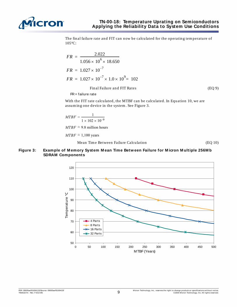
TN-00-18 Temperature Uprating on SemiconductorsApplying the Reliability Data to System Use Conditions
The final failure rate and FIT can now be calculated for the operating temperature of 105degC
Final Failure and FIT Rates (EQ 9)
FR = failure rate
With the FIT rate calculated the MTBF can be calculated In Equation 10 we are assuming one device in the system See Figure 3
Mean Time Between Failure Calculation (EQ 10)
Figure 3 Example of Memory System Mean Time Between Failure for Micron Multiple 256Mb SDRAM Components
FR 20221056 106times 18650times---------------------------------------------------=
FR 1027 10 7ndashtimes=
FR 1027 10 7ndashtimes 10 109 102=timestimes=
MTBF 1 1 times 102 times 10ndash9
98 million hours
1100 years
--------------------- =
MTBF ~ ~
MTBF ~ ~
50
60
70
80
90
100
110
120
0 50 100 150 200 250 300 350 400 450 500
MTBF (Years)
Tem
per
atu
re deg
C
4 Parts8 Parts16 Parts32 Parts
PDF 09005aef81694133Source 09005aef8169415f Micron Technology Inc reserves the right to change products or specifications without noticeTN0018fm - Rev F 510 EN 9 copy2004 Micron Technology Inc All rights reserved
TN-00-18 Temperature Uprating on SemiconductorsPackage Reliability
Package ReliabilityPackage reliability is generally not a concern at constant operating temperatures below 125degC However reliability predictions can be made if conditions in the use environment are known and acceleration factors are calculated Data provided by Micron in device qualification reports or acquired by applying knowledge of expected failure mechanisms in the use environment can be used to calculate the acceleration factors
The Hallberg-Peck acceleration model is commonly used for temperature and humidity stress
Hallberg-Peck (EQ 11)
WhereEA = Activation energy of defect mechanism (09 commonly used)Boltzmannrsquos constant (k) = 86174 times 10ndash5 eVKRHs = Stress test environment relative humidityRHo = Operating use environment relative humidityTs = Stress test environment temperature To = Operating use environment temperature
Two common acceleration models are used to calculate thermal cycling stress
Coffin-Manson (EQ 12)
Modified Coffin-Manson (SnPb solder joints) (EQ 13)
Wherem = Exponent dependent on defect mechanism and material ΔTs = Stress test thermal cycle temperature change ΔTo = Operating use thermal cycle temperature changeFo = Operating use thermal cycling frequencyFs = Stress test thermal cycling frequencyTs = Maximum temperature during stress test thermal cycleTo = Maximum temperature during operating use thermal cycle
SummaryWhen exceeding the specified device temperature limits the customer faces three concerns First the functionality and performance of the device must be considered and the system design must be adjusted accordingly Second device reliability is reduced which can be calculated using the proper reliability equations Finally temper-atures below +125degC are not a concern for package reliability but temperature cycling can be a concern and should be avoided
AFRHsRHo----------⎝ ⎠⎛ ⎞
3etimes
EAk
------⎝ ⎠⎛ ⎞ 1
To----- 1
Ts-----ndash⎝ ⎠
⎛ ⎞times=
AFΔTsΔTo---------⎝ ⎠⎛ ⎞
m=
AFΔTsΔTo---------⎝ ⎠⎛ ⎞ 19˜ Fo
Fs------⎝ ⎠⎛ ⎞
1 3frasle
001 Ts Tondash( )times[ ]timestimes=
PDF 09005aef81694133Source 09005aef8169415f Micron Technology Inc reserves the right to change products or specifications without noticeTN0018fm - Rev F 510 EN 10 copy2004 Micron Technology Inc All rights reserved
TN-00-18 Temperature Uprating on SemiconductorsSummary
Uprating can be performed on many levels The military for instance through its COTS program buys commercially-rated semiconductors and re-evaluates device suitability for its temperature-rated applications This can be accomplished using a variety of methods including common practices of parameter conformance parameter recharac-terization stress balancing and higher assembly level testing13 However these processes are very expensive and add to the cost of the components18
At the other extreme the user could simply take commercially rated devices assess their critical function parameters and decreased reliability and simply design the system around these issues
Many semiconductor manufacturers design significant margin into their products However semiconductor manufacturers who provide products for multiple temperature specification ranges as Micron does generally do not have different device fabrication processes based on the expected temperature range of the application For example commercial and industrial devices are generally from the same fabrication process and therefore have equivalent intrinsic device reliability The primary difference is that the industrial devices have been screened for data sheet functionality at the necessary temperature extremes13
Before products are uprated a thorough understanding of the thermal environment is needed Uprating can be an expensive process If devices are never subjected to extended temperatures there is probably no reason to add the costs associated with uprating even if the system has been specified to extended temperatures For details on thermal measurements see Micronrsquos Thermal Application Technical Note TN-00-08
PDF 09005aef81694133Source 09005aef8169415f Micron Technology Inc reserves the right to change products or specifications without noticeTN0018fm - Rev F 510 EN 11 copy2004 Micron Technology Inc All rights reserved
TN-00-18 Temperature Uprating on SemiconductorsReferences
References
Book References1 Harman G and Harper CA Wire Bonding in Microelectronics Materials Processes
Reliability and Yield 2nd Ed McGraw-Hill New York 1997 2 Kirschman R High-Temperature Electronics IEEE Press New York 19993 Lall P Precht M G and Hakim E B Influence of Temperature on Microelectronics
CRC Press Boca Raton 1997 4 McCluskey F P Grzybowski R and Podlesak T High-Temperature Electronics CRC
Press Boca Raton 1997 5 Amerasekera E Ajith Najm Farid N Failure Mechanisms in Semiconductor Devices
2nd Ed John Wiley amp Sons Hoboken 1998
Paper References6 Barker D ldquoRuggedizing Laptop Computers for Mobile Applicationsrdquo Presented at the
first workshop on use of components outside specified temperature limits CALCE EPRC University of Maryland College Park January 23 1997
7 Biddle S ldquoBeyond Quality ndash Assuring the Reliability of Plastic Encapsulated Inte-grated Circuitsrdquo COTS Journal March 2003
8 Condra L Das D Pendse N and Pecht M ldquoJunction Temperature Considerations in Evaluating Electronic Parts for Use Outside Manufacturers-Specified Temperature Rangesrdquo IEEE Trans Comp Pack Tech Vol 24 pp 721ndash728 December 2001
9 Das D Pendse N Pecht M and Wilkinson C ldquoDeciphering the Deluge of Datardquo Circuits and Devices September 2000
10 Das D Pendse N Pecht M and Wilkinson C ldquoParameter Recharacterization A Method of Thermal Upratingrdquo IEEE Trans Comp Pack Tech Vol 24 pp 729ndash737 December 2001
11 Dasgupta A et al ldquoDoes the Cooling of Electronics Increase Reliabilityrdquo Presented at the Proc Thermal Stresses 95 Conference No 231 1995
12 Davila-Rieth K ldquoUprating Assemblies for Military Computer Systemsrdquo Presented at the first workshop on use of components outside specified temperature limits CALCE EPRC University of Maryland College Park January 23 1997
13 Humphrey D et al ldquoAn Avionics Guide to Uprating of Electronic Partsrdquo IEEE Trans Comp Pack Tech Vol 23 pp 595ndash599 September 2000
14 Kroger R ldquoManufacturer Part Assessment A Pragmatic Approachrdquo Presented at the first workshop on use of components outside specified temperature limits CALCE EPRC University of Maryland College Park January 23 1997
15 Lall P et al ldquoCharacterization of Functional Relationship Between Temperature and Microelectronic Reliabilityrdquo Microelecton Vol 35 No 3 pp 377ndash402 March 1995
16 McCluskey P et al ldquoUprating of Commercial Parts for Use in Harsh Environmentsrdquo CALCE EPRC Rep November 1996
17 Ng K K ldquoA Survey of Semiconductor Devicesrdquo IEEE Trans Electron Devices Vol 43 pp 1760ndash1766 October 1996
18 Pecht M ldquoIssues Affecting Early Affordable Access to Leading Electronics Technolo-gies by the US Military and Governmentrdquo Circuit World Vol 22 No 2 pp 7ndash15 1996
19 Pendse N Thomas D Das D and Precht M ldquoUprating of a Single Inline Memory Modulerdquo IEEE Trans Comp Pack Tech Vol 25 No 2 pp 266ndash269 June 2002
PDF 09005aef81694133Source 09005aef8169415f Micron Technology Inc reserves the right to change products or specifications without noticeTN0018fm - Rev F 510 EN 12 copy2004 Micron Technology Inc All rights reserved
TN-00-18 Temperature Uprating on SemiconductorsReferences
20 Suhir E ldquoAccelerated Life Testing (ALT) in Microelectronics and Photonics Its Role Attributes Challenges Pitfalls and Interaction With Qualification Testsrdquo Journal of Electronic Packaging Vol124 pp 281ndash290 September 2002
21 Wright M et al ldquoUprating Electronic Components for use Outside their Tempera-ture Specification Limitsrdquo IEEE Trans Comp Packaging and Manufacturing Tech-nology-Part A Vol 20 pp 252ndash256 June 1997
Micron References22 Quality and Reliability Handbook23 256Mb Qualification Document24 A Gallo Fink J ldquoReliability of Commercial Plastic Encapsulated Microelectronics at
Temperatures from +125degC to +300degCrdquo Dexter Technical Paper July 1999
8000 S Federal Way PO Box 6 Boise ID 83707-0006 Tel 208-368-3900wwwmicroncomproductsupport Customer Comment Line 800-932-4992
Micron and the Micron logo are trademarks of Micron Technology Ince-MMCtrade is a trademark of the JEDEC Solid State Technology Association RLDRAM is a registered trademark of Qimonda AG in various
countries and is used by Micron Technology Inc under license from QimondaAll other trademarks are the property of their respective owners
PDF 09005aef81694133Source 09005aef8169415f Micron Technology Inc reserves the right to change products or specifications without noticeTN0018fm - Rev F 510 EN 13 copy2004 Micron Technology Inc All rights reserved
TN-00-18 Temperature Uprating on SemiconductorsRevision History
Revision HistoryRev F 510
bull Updated Table 1 ldquoJunction Temperature Functionalityrdquo on page 2
Rev E 508bull Updated Table 1 ldquoJunction Temperature Functionalityrdquo on page 2
Rev D 107bull Updated Table 1 ldquoJunction Temperature Functionalityrdquo on page 2bull Edited for readabilitybull Corrected Table 2 ldquoIndustry-Standard Typical Junction Temperature Limitsrdquo on
page 2 Under the hood temperature to -40-150
Rev C 1106bull Updated ldquoDevice Reliabilityrdquo sectionbull Added ldquoLong-Term Reliabilityrdquo ldquoTemperature Acceleration Factorrdquo ldquoOverall Acceler-
ation Factorrdquo ldquoFailure Rate Calculationrdquo and ldquoApplying the Reliability Data to System Use Conditionsrdquo sections
Rev B 1105bull Updated templatebull Corrected typos Equation 2 on page 2 TN-00-08 reference on page 10 and Boltz-
mannrsquos constant from 86171 to 86174 on page 10
Rev A 1004bull Initial release
PDF 09005aef81694133Source 09005aef8169415f Micron Technology Inc reserves the right to change products or specifications without noticeTN0018fm - Rev F 510 EN 14 copy2004 Micron Technology Inc All rights reserved
- Introduction
- Device Functionality
- Device Reliability
- Long-Term Reliability
- Temperature Acceleration Factor
-
- Voltage Acceleration Factor
-
- Overall Acceleration Factor
- Failure Rate Calculation
- Applying the Reliability Data to System Use Conditions
-
- System FIT Rate Example
-
- Package Reliability
- Summary
- References
-
- Book References
- Paper References
- Micron References
-
- Revision History
-

TN-00-18 Temperature Uprating on SemiconductorsReferences
20 Suhir E ldquoAccelerated Life Testing (ALT) in Microelectronics and Photonics Its Role Attributes Challenges Pitfalls and Interaction With Qualification Testsrdquo Journal of Electronic Packaging Vol124 pp 281ndash290 September 2002
21 Wright M et al ldquoUprating Electronic Components for use Outside their Tempera-ture Specification Limitsrdquo IEEE Trans Comp Packaging and Manufacturing Tech-nology-Part A Vol 20 pp 252ndash256 June 1997
Micron References22 Quality and Reliability Handbook23 256Mb Qualification Document24 A Gallo Fink J ldquoReliability of Commercial Plastic Encapsulated Microelectronics at
Temperatures from +125degC to +300degCrdquo Dexter Technical Paper July 1999
8000 S Federal Way PO Box 6 Boise ID 83707-0006 Tel 208-368-3900wwwmicroncomproductsupport Customer Comment Line 800-932-4992
Micron and the Micron logo are trademarks of Micron Technology Ince-MMCtrade is a trademark of the JEDEC Solid State Technology Association RLDRAM is a registered trademark of Qimonda AG in various
countries and is used by Micron Technology Inc under license from QimondaAll other trademarks are the property of their respective owners
PDF 09005aef81694133Source 09005aef8169415f Micron Technology Inc reserves the right to change products or specifications without noticeTN0018fm - Rev F 510 EN 13 copy2004 Micron Technology Inc All rights reserved
TN-00-18 Temperature Uprating on SemiconductorsRevision History
Revision HistoryRev F 510
bull Updated Table 1 ldquoJunction Temperature Functionalityrdquo on page 2
Rev E 508bull Updated Table 1 ldquoJunction Temperature Functionalityrdquo on page 2
Rev D 107bull Updated Table 1 ldquoJunction Temperature Functionalityrdquo on page 2bull Edited for readabilitybull Corrected Table 2 ldquoIndustry-Standard Typical Junction Temperature Limitsrdquo on
page 2 Under the hood temperature to -40-150
Rev C 1106bull Updated ldquoDevice Reliabilityrdquo sectionbull Added ldquoLong-Term Reliabilityrdquo ldquoTemperature Acceleration Factorrdquo ldquoOverall Acceler-
ation Factorrdquo ldquoFailure Rate Calculationrdquo and ldquoApplying the Reliability Data to System Use Conditionsrdquo sections
Rev B 1105bull Updated templatebull Corrected typos Equation 2 on page 2 TN-00-08 reference on page 10 and Boltz-
mannrsquos constant from 86171 to 86174 on page 10
Rev A 1004bull Initial release
PDF 09005aef81694133Source 09005aef8169415f Micron Technology Inc reserves the right to change products or specifications without noticeTN0018fm - Rev F 510 EN 14 copy2004 Micron Technology Inc All rights reserved
- Introduction
- Device Functionality
- Device Reliability
- Long-Term Reliability
- Temperature Acceleration Factor
-
- Voltage Acceleration Factor
-
- Overall Acceleration Factor
- Failure Rate Calculation
- Applying the Reliability Data to System Use Conditions
-
- System FIT Rate Example
-
- Package Reliability
- Summary
- References
-
- Book References
- Paper References
- Micron References
-
- Revision History
-