ATLAS 実験における Fast TracKer (FTK) の開発研究 ~ A Hardware Tracking Trigger at LVL1.5 ~
Upgrades of the Tracker and Trigger of the CMS …hallg/CMS_links/OSC_1114/OSC_report_1114.pdf ·...
20
11 November 2014 1 University of Bristol Brunel University London Imperial College London Rutherford Appleton Laboratory Upgrades of the Tracker and Trigger of the CMS experiment at the CERN LHC 1 Executive Summary .......................................................................................................................... 2 2. Project history and recent developments ......................................................................................... 2 2.1 LHC upgrade schedule and planning.......................................................................................... 3 2.2 CMS planning ............................................................................................................................. 4 2.3 UK adaptation to CMS planning..................................................................................................5 2.4 Simulation studies ....................................................................................................................... 5 3. Work Package 1: Management ........................................................................................................ 7 4. Work Package 2: Outer Tracker Readout ........................................................................................ 8 4.1 Objectives ...................................................................................................................................8 4.2 Progress...................................................................................................................................... 8 4.3 Deliverables .............................................................................................................................. 12 4.4 Staff on project .......................................................................................................................... 12 4.5 Expenditure ............................................................................................................................... 12 5. Work Package 3: Level-1 Trigger ..................................................................................................13 5.1 Objectives .................................................................................................................................13 5.2 Progress to date........................................................................................................................ 13 5.3 Overview of CMS plans ............................................................................................................15 5.4 Staff on project .......................................................................................................................... 15 5.5 Expenditure ............................................................................................................................... 16 5.6 Deliverables .............................................................................................................................. 16 6 Risk register ....................................................................................................................................17 7 Finances .........................................................................................................................................17 8 Gantt charts ....................................................................................................................................18 9 Milestones .......................................................................................................................................19
-
Upload
nguyenduong -
Category
Documents
-
view
228 -
download
1
Transcript of Upgrades of the Tracker and Trigger of the CMS …hallg/CMS_links/OSC_1114/OSC_report_1114.pdf ·...

11 November 2014
1
University of Bristol Brunel University London Imperial College London Rutherford Appleton Laboratory
Upgrades of the Tracker and Trigger of the CMS experiment at the CERN LHC
1 Executive Summary .......................................................................................................................... 2 2. Project history and recent developments ......................................................................................... 2
2.1 LHC upgrade schedule and planning .......................................................................................... 3 2.2 CMS planning ............................................................................................................................. 4 2.3 UK adaptation to CMS planning .................................................................................................. 5 2.4 Simulation studies ....................................................................................................................... 5
3. Work Package 1: Management ........................................................................................................ 7 4. Work Package 2: Outer Tracker Readout ........................................................................................ 8
4.1 Objectives ................................................................................................................................... 8 4.2 Progress ...................................................................................................................................... 8 4.3 Deliverables .............................................................................................................................. 12 4.4 Staff on project .......................................................................................................................... 12 4.5 Expenditure ............................................................................................................................... 12
5. Work Package 3: Level-1 Trigger .................................................................................................. 13 5.1 Objectives ................................................................................................................................. 13 5.2 Progress to date ........................................................................................................................ 13 5.3 Overview of CMS plans ............................................................................................................ 15 5.4 Staff on project .......................................................................................................................... 15 5.5 Expenditure ............................................................................................................................... 16 5.6 Deliverables .............................................................................................................................. 16
6 Risk register .................................................................................................................................... 17 7 Finances ......................................................................................................................................... 17 8 Gantt charts .................................................................................................................................... 18 9 Milestones ....................................................................................................................................... 19
11 November 2014
2
1 Executive Summary The new project started in April 2013; it continues work on the tracker and trigger begun in the
previous R&D project. For the Phase I upgrades of the L1 calorimeter trigger, this is a construction project.
In the last six months there has been further progress with the UK activities: • There has been steady progress with the evolution of the final CBC design, with a
manufacturing submission foreseen in about one year, and total dose radiation and SEU tests have been carried out.
• The FC7 general purpose data acquisition board has been effectively handed over to other projects, for the upgraded CMS TTC (TCDS) system, and the CMS Phase I pixel upgrade.
• Manufacturing of the MP7 is under way with two companies, one from the UK; deliveries are broadly on schedule and further orders are being placed to meet the full needs of the trigger project.
• There has been good progress in the development of algorithms and firmware for the Level-1 trigger with increasing confidence that they can be installed within the FPGA resources, which is challenging.
• Several iterations of the overall project plan for the Level-1 trigger have been necessitated by progress in the project, mainly concerning late deliveries from outside the UK. This is under review by the top level of CMS management, in addition to the Trigger PM, with the intention to maintain the delivery of the TDR trigger for operation in 2016.
• A Time Multiplexed Trigger architecture for the track-trigger needed for the Phase II upgraded CMS has been further studied, and we are making good progress in developing the ideas for implementation of a demonstrator system over the next year, including algorithms in firmware.
The UK project is on the envisaged schedule but the long term plan remains under review because overall CMS objectives for HL-LHC have been evolving gradually. As the long term LHC schedule has changed, the CMS plans for Phase II have altered, which has had a knock-on effect. Progress with the Phase I trigger upgrade has been contentious and is the subject of greatly increased scrutiny by CMS management.
2. Project history and recent developments The LHC upgrade is proposed to take place in two main stages, with an increase in luminosity
reaching ~2.5 1034 cm-2s-1 a couple of years after 2015 in LHC Run 2, then after a two to three year shutdown from 2023, to ~5 x 1034 cm-2s-1 levelled luminosity, denoted as Phase II at the High Luminosity (HL)-LHC. A total of 3000 fb-1 in integrated luminosity over about a decade is the goal.
The current phase of the project began on 1 April 2013. There are two technical work packages: WP2 for the Phase II outer tracker readout R&D for HL-LHC; WP3 for the calorimeter trigger construction for Phase I, starting in 2015, and further R&D aimed at Phase II.
CMS and the LHC are currently approaching the end of Long Shutdown 1 (LS1) and should restart with 6.5 TeV beams in March 2015; this remains on schedule and CERN North Area beams were available as planned in October 2014.
CMS shutdown activities are also proceeding broadly according to schedule. The tracker has been operated at low temperature, with improved dry gas circulation to control humidity. The new beam pipe was installed on schedule followed by bake-out, which had an impact (as planned) on other activities at Point 5. Recommissioning is under way and global and cosmic ray data taking runs are taking place regularly. The main issue which arose during the summer was a problem found with pixel barrel modules where about a quarter of one quadrant was found to be defective, and originally attributed to possible overvoltage. The detector was dismantled and transported to PSI for repairs and diagnosis. The problems are now understood to be related to the presence of solder flux residue trapped in 25 µm channels in the High Density Interconnect flex-hybrid which supports the pixel ROC

11 November 2014
3
ASIC and sensor assemblies, probably exacerbated by exposure to humidity. However, repairs have been completed successfully and the pixel detector will be reinstalled in CMS at the end of November. Although this has certainly had an impact on the planning, it has been accommodated within the contingency available and is not likely to affect start-up in 2015.
2.1 LHC upgrade schedule and planning
Figure 2.1: The most recent LHC schedule for 2015.
The schedule for 2015 is now fairly clear (fig 2.1) and has been adapted to the wishes of both ATLAS and CMS for 25 ns operation. It has some relevance to the Phase I trigger commissioning. The main phases are
• Low intensity commissioning during March and April • First physics with a few isolated bunches, in early May • First scrubbing run (50 ns) in late May • 50 ns operation, over three weeks where the intensity is ramped up to 1380 bunches/beam
11 November 2014
4
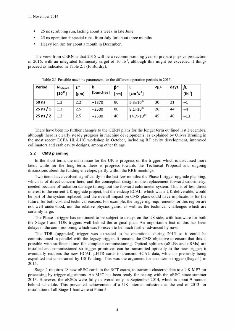
• 25 ns scrubbing run, lasting about a week in late June • 25 ns operation + special runs, from July for about three months • Heavy ion run for about a month in December. The view from CERN is that 2015 will be a recommissioning year to prepare physics production
in 2016, with an integrated luminosity target of 10 fb-1, although this might be exceeded if things proceed as indicated in Table 2.1 (F. Bordry).
Table 2.1 Possible machine parameters for the different operation periods in 2015.
Period Np/bunch [1011]
ε* [µm]
k [bunches]
β* [cm]
L [cm-‐2s-‐1]
<µ> days ∫L [fb-‐1]
50 ns 1.2 2.2 ≈1370 80 5.3×1033 30 21 ≈1 25 ns / 1 1.2 2.5 ≈2500 80 8.1×1033 26 44 ≈4 25 ns / 2 1.2 2.5 ≈2500 40 14.7×1033 45 46 ≈13
There have been no further changes to the CERN plans for the longer term outlined last December,
although there is clearly steady progress in machine developments, as explained by Oliver Brüning in the most recent ECFA HL-LHC workshop in October, including RF cavity development, improved collimators and crab cavity designs, among other things.
2.2 CMS planning
In the short term, the main issue for the UK is progress on the trigger, which is discussed more later, while for the long term, there is progress towards the Technical Proposal and ongoing discussions about the funding envelope, partly within the RRB meetings.
Two items have evolved significantly in the last few months: the Phase I trigger upgrade planning, which is of direct concern here, and the conceptual design of the replacement forward calorimetry, needed because of radiation damage throughout the forward calorimeter system. This is of less direct interest to the current UK upgrade project, but the endcap ECAL, which was a UK deliverable, would be part of the system replaced, and the overall impact on CMS plans could have implications for the future, for both cost and technical reasons. For example, the triggering requirements for this region are not well understood, nor the relative physics gains, as well as the technical challenges which are certainly large.
The Phase I trigger has continued to be subject to delays on the US side, with hardware for both the Stage-1 and TDR triggers well behind the original plan. An important effect of this has been delays in the commissioning which was foreseen to be much further advanced by now.
The TDR (upgraded) trigger was expected to be operational during 2015 so it could be commissioned in parallel with the legacy trigger. It remains the CMS objective to ensure that this is possible with sufficient time for complete commissioning. Optical splitters (oSLBs and oRMs) are installed and commissioned so trigger primitives can be transmitted optically to the new trigger; it eventually requires the new HCAL µHTR cards to transmit HCAL data, which is presently being expedited but constrained by US funding. This was the argument for an interim trigger (Stage-1) in 2015.
Stage-1 requires 18 new oRSC cards in the RCT crates, to transmit clustered data to a UK MP7 for processing by trigger algorithms. An MP7 has been ready for testing with the oRSC since summer 2013. However, the oRSCs were fully delivered only in September 2014, which is about 9 months behind schedule. This prevented achievement of a UK internal milestone at the end of 2013 for installation of all Stage-1 hardware at Point 5.

11 November 2014
5
As previously reported, the UK groups carried out a successful Time Multiplexed Trigger (TMT) integration test in September 2013. This demonstrated several important things, including that MP7s could be deployed in both Layer-1 and Layer-2 of the TDR calorimeter trigger.
The availability of US Layer-1 hardware, the CTP7, is now crucial. This board was first manufactured at the end of 2013 but few were available in CERN until mid-2014, so only one was available for the Layer-1-Layer-2 integration test scheduled for July. 36 CTP7 boards are required for Layer-1; about 4 are currently available, which are pre-production boards. The schedule for further deliveries is a concern, and the plan now foresees a commitment to provide at least 8 CTP7s in CERN by late January, or a backup plan will be invoked.
The Trigger PMs will organize a review of the 2016 calorimeter trigger project to take place in late January 2015, with the aim to assess readiness and to take any necessary decisions to ensure delivery of the TDR trigger by 1 August 2015 at the latest.
A CMS Phase II Technical Proposal was prepared for submission to the LHCC in September 2014
and was discussed with the LHCC referees. The reaction was generally positive but they noted the difficulties in assessing rigorously the physics performance of the upgraded detector taking into account the novelty of some of the technologies and of the extreme conditions from the pileup point of view. Although much progress has been made, a full simulation and optimized reconstruction is needed to allow performance assessment, which is particularly important for some parts of the proposed new detector, especially the forward calorimetry.
A new schedule was therefore proposed for the LHCC TP submission, of March 2015 with an advance draft in November. This is also better aligned to a decision on the forward calorimeter, now foreseen to be February 2015. It would allow CMS to turn its attention to TDR preparation during the summer of 2015. The Tracker TDR is foreseen to be ready by the end of 2016.
A series of steps are foreseen to reach the calorimeter choice, with some of the major ones listed below:
• Dec: Extended dedicated meeting on technical milestones and performance • Jan: Further discussions on resources, schedule and technical aspects • Jan: Extended dedicated meeting to start approval of reconstruction and physics studies • Late Jan: Closed session of internal review panel with the proponents • Feb: Submission and presentation of the review report to the collaboration • Feb: CMS MB discussion and recommendation • Feb: Presentation of proposed choice to the collaboration and CB endorsement The October 2013 RRB was given an outline estimate from CMS broadly justifying the physics
and technical objectives and providing a cost estimate amounting to 270 MCHF, plus R&D. These costs have been scrutinised internally over the last few months and reported to the October 2014 RRB. The outcome did not change the total significantly, although some important detailed estimates were revised. There have been further discussions between CERN and the funding agencies about funding and resources; this is ongoing.
2.3 UK adaptation to CMS planning
Of late, the main issues have been uncertainties in the Phase I trigger project which are discussed in several other places in this report.
2.4 Simulation studies
As described last time, simulation studies are an area relevant to both WP2 and WP3. The eventual track-trigger will take data from the 2S- and PS-modules and transfer them off-detector for Level-1 track finding and incorporation into the rest of the trigger, which is not yet well defined. In the first
11 November 2014
6
instance, these studies should demonstrate track-finding algorithms which must be implemented in firmware, and estimate efficiency and latency.
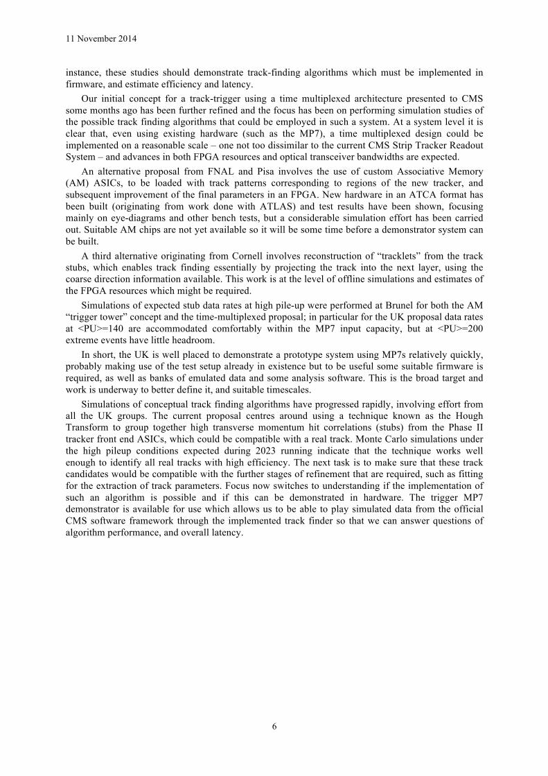
Our initial concept for a track-trigger using a time multiplexed architecture presented to CMS some months ago has been further refined and the focus has been on performing simulation studies of the possible track finding algorithms that could be employed in such a system. At a system level it is clear that, even using existing hardware (such as the MP7), a time multiplexed design could be implemented on a reasonable scale – one not too dissimilar to the current CMS Strip Tracker Readout System – and advances in both FPGA resources and optical transceiver bandwidths are expected.
An alternative proposal from FNAL and Pisa involves the use of custom Associative Memory (AM) ASICs, to be loaded with track patterns corresponding to regions of the new tracker, and subsequent improvement of the final parameters in an FPGA. New hardware in an ATCA format has been built (originating from work done with ATLAS) and test results have been shown, focusing mainly on eye-diagrams and other bench tests, but a considerable simulation effort has been carried out. Suitable AM chips are not yet available so it will be some time before a demonstrator system can be built.
A third alternative originating from Cornell involves reconstruction of “tracklets” from the track stubs, which enables track finding essentially by projecting the track into the next layer, using the coarse direction information available. This work is at the level of offline simulations and estimates of the FPGA resources which might be required.
Simulations of expected stub data rates at high pile-up were performed at Brunel for both the AM “trigger tower” concept and the time-multiplexed proposal; in particular for the UK proposal data rates at <PU>=140 are accommodated comfortably within the MP7 input capacity, but at <PU>=200 extreme events have little headroom.
In short, the UK is well placed to demonstrate a prototype system using MP7s relatively quickly, probably making use of the test setup already in existence but to be useful some suitable firmware is required, as well as banks of emulated data and some analysis software. This is the broad target and work is underway to better define it, and suitable timescales.
Simulations of conceptual track finding algorithms have progressed rapidly, involving effort from all the UK groups. The current proposal centres around using a technique known as the Hough Transform to group together high transverse momentum hit correlations (stubs) from the Phase II tracker front end ASICs, which could be compatible with a real track. Monte Carlo simulations under the high pileup conditions expected during 2023 running indicate that the technique works well enough to identify all real tracks with high efficiency. The next task is to make sure that these track candidates would be compatible with the further stages of refinement that are required, such as fitting for the extraction of track parameters. Focus now switches to understanding if the implementation of such an algorithm is possible and if this can be demonstrated in hardware. The trigger MP7 demonstrator is available for use which allows us to be able to play simulated data from the official CMS software framework through the implemented track finder so that we can answer questions of algorithm performance, and overall latency.

11 November 2014
7
3. Work Package 1: Management A reminder of the project management is included below. A replacement for P. Brambilla has been
appointed and we have reorganised at Imperial some of the ordering responsibilities.
WP Manager Institute Role 1 G Hall, PI Imperial Overall management, budgetary responsibility and
supervising procurements, interface to CMS, as UK CMS PI and CMS Management Board and Tracker Management Board member.
2 M Raymond Imperial Overall responsible for CBC specifications, interface to module design team, chip testing and module evaluation and CMS planning
M Prydderch RAL TD Manager of ASIC design team in RAL
3 A Tapper Imperial Based in CERN with supervisory responsibilities for G. Iles, Imperial College engineer, also based in CERN.
D Newbold Bristol UK firmware and software coordinator. Trigger Institution Board chair.

11 November 2014
8
4. Work Package 2: Outer Tracker Readout
4.1 Objectives
The objectives of work package 2 as stated in the proposal are: • To complete the development of a readout and triggering chip suitable for the 2S-PT module,
bringing the chip to a final state ready for mass production. • To develop the hardware and software required for the large-scale production testing
procedures, and to deliver tested wafers to the CMS experiment. • To play a major role in construction, definition and evaluation of prototype modules. • To contribute to development of ancillary chips required for the 2S-PT module, and to
participate in the PS-PT module development. • To contribute to the future large-scale module production programme, and to participate in
integration and commissioning activities. The 2S-PT module concept meets the HL-LHC challenge of providing tracking information to the
level 1 trigger decision in CMS by providing coordinates of high-pT stubs formed by correlating signals occurring in two closely spaced sensor layers. Developed in the UK, the CBC2 chip is a 130nm CMOS coarse pitch (250 µm) bump-bondable ASIC, integrating 254 channels to allow correlation between two sets of 127 strip channels from 2 separate sensor layers. The correlation circuitry implements cluster width discrimination and looks for coincidence between a cluster in a seed layer and a cluster occurring within a programmable window in the other layer. In this prototype version of the chip a positive correlation simply results in the output of a prompt trigger pulse.
4.2 Progress
Since the last report we have completed the outstanding ionizing irradiation and single event upset (SEU) tests required on the CBC2 chip. The 2S system definition has now converged, allowing design of the next version of the chip (CBC3) to begin. The 8CBC2flex full-size hybrids constructed using fully flexible technology (glued to a rigid support structure) have been demonstrated to work well and are awaiting the production of full-size sensors before modules can be assembled. At least one other manufacturer of flexible hybrids has been identified, and 2 more CBC2 wafers have been probe-tested and diced to allow further prototyping.
Initial room temperature X-ray ionizing irradiation tests of the CBC2, reported last time, showed an unexpected increase in supply current after a few Mrads, which was dose-rate dependent and which fell back to pre-irradiation levels once irradiation was stopped, and which also disappeared at higher dose levels. We have now followed up with a further test where the chip temperature was held at -15 degrees, and subsequently with areas of the chip masked during irradiation to isolate regions performing different functions. The lower temperature operation was found to slow down the supply current recovery rate by a factor ~5, but recovery still occurred. The masking operations isolated the source of the extra current to the pipeline region of the chip. We now suspect the source of the current is in the minimum size NMOS transistors used in the pipeline cells (it was not thought necessary to implement these using a rad-hard enclosed geometry layout), and some of the observed symptoms of the effect have been confirmed by simulation. The effect should not impact significantly on any module tests using CBC2 readout, and we propose to implement a rad-hard layout to eliminate the effect altogether in the CBC3.
We have now irradiated the CBC2 up to a total dose of 41 Mrads, well in excess of the total dose requirements in the outer tracker region at HL-LHC, and figure 4.1 shows some of the results obtained where no significant degradation in performance can be seen.
We have now also completed the SEU testing of the CBC2 at the Universite Catholique de Louvain cyclotron facility using a 62 MeV proton beam, which simulates the HL-LHC SEU environment. Figure 4.2 shows the setup in the beam. Tests included looking for upsets in the pipeline logic, and the I2C programmable registers in the chip which determine operational modes, bias settings, and comparator offsets.

11 November 2014
9
The pipeline logic was specifically designed for SEU resistance using special circuit techniques, and was found in the test to be very robust with only 3 errors detected in 3.3 hours irradiation time. At HL-LHC this can be extrapolated to 0.036 ± 0.020 upsets per chip per hour. This type of upset can be recovered by a fast reset to the chip which re-initialises the pipeline logic with minimal dead time.
The I2C registers were designed for SEU resistance by triplicating each bit and using logic to select the majority value. In addition an external refresh signal could be provided to restore all 3 bits to the majority, thus removing any upset bit. Test results here showed an upset rate <1 bit per chip per hour. In some cases more than one bit was upset in a single register, and the refresh signal was not found to be completely effective at eliminating upsets. A review of the chip layout suggests that the proximity of the triplicated logic cells is allowing a single SEU strike to flip more than one bit. The complete reprogramming of all I2C registers in the chip is relatively time consuming, so we propose to improve the I2C register SEU robustness for the CBC3 by using the proven hard-by-design cells used in the pipeline logic.
Figure 4.1. radiation test results up to 41 Mrads
Figure 4.2. SEU test setup at Universite Catholique de Louvain
s-curve measurementspre-rad10 Mrads20 Mrads~30 Mrads41 Mrads
130
120
110
100
90250200150100500
3.0
2.5
2.0
1.5
1.0
0.5
0.0250200150100500
3.0
2.5
2.0
1.5
1.0
0.5
0.0250200150100500
pedestals noise
test pulse noise
s-curves mid-points
pedestals
test pulseVC
TH u
nits
channel number
rms
VC
TH u
nits
channel number
CBC2

11 November 2014
10
With our colleagues in the CMS electronics system team we have continued to make progress with
the outer tracker readout system definition and only a very few minor details remain to be resolved. The goal has been to maintain as much compatibility between the 2S and PS readout systems as possible. The requirements for the CBC3 are now almost fully defined and a specification document is therefore close to completion.
Figure 4.3. CBC3 design schedule
Figure 4.3 shows the CBC3 design schedule, leading to chips in hand by Summer 2016. The modification and optimisation of the correlation/stub finding logic to include half strip resolution has been completed. The logic for gathering up to 3 stubs and exporting their addresses has been completed to layout, along with the L1 counter. The data assembly circuitry is currently being worked on and a top level simulation has been constructed to verify the synchronising of data from different time domains within the chip.
The technique of wrapping a flexible circuit around a carbon fibre support is our preferred method of hybrid construction and at the time of the last report the 8CBC2flex first prototype hybrids, manufactured by AEMTEC, had only just arrived. Further testing has confirmed full functionality and these will be used to construct full-size modules and a production of suitable sensors is currently planned. It is important to have more than one possible hybrid manufacturer and alternative flex hybrid manufacturers have now been identified and one has been selected (ENGENT) for a prototype production run. To provide sufficient chips for these tests we have probe-tested a further 2 wafers and subsequently had them diced. We have now probed a total of 4 wafers from the 8 delivered and the yield remains high at >95%.
Work has continued in the development of test-stands to support hybrid and module prototyping and eventual production requirements. A standard test stand kit has now been defined, including GLIB, interface cards (provided by Bristol and IC) and 2-chip CBC2 hybrid. Six of these kits have now been assembled, tested and delivered to user (non-UK or CERN) institutes where they are being used for module, hybrid and DAQ system tests. The hardware for the 8-chip CBC2 hybrids was also completed, and these hybrids have been tested at CERN and UK institutes.
The test stand software has been completely rewritten to improve efficiency and performance. CERN have provided a middleware layer in the form of a C++ library that interfaces with the

11 November 2014
11
firmware, and Bristol are providing the high-level control scripts and GUI. Most of this software framework is already in use, and a stable release is imminent.
FC7 developments
The FC7 (FMC carrier - Xilinx Series 7) is based on the MP7 and CERN GLIB cards with the ability to host up to two FMC (FPGA Mezzanine Card) modules and support signalling rates up to 10Gbps. It is a flexible, general purpose card allowing it to be deployed across many applications in CMS and its development has been shared with engineers from CERN.
Over 80 boards have now been produced for use in CMS. We recall that prototyping took place in August 2013, following which the design was resubmitted to two different manufacturers (Exception-PCB [UK], Hapro [Norway]). This division was intended to act as both as a pre-production run before production in 2014, but also as a means of reducing risk, to verify the board manufacture and assembly issues for the imminent MP7 production, as well as the FC7.
The majority of FC7s have been manufactured via Hapro, who demonstrated excellent assembly quality and high yield in a pre-production run earlier this year. The boards have been fully qualified in an acceptance test stand at CERN, where the final yield for the run stands at over 97%. Issues or failures were reported back to Hapro who have been extremely responsive in either correcting the failures or updating their practices so that overall turn-around times are kept short.
The FC7s that have been produced are now being installed in P5 as part of the Trigger, Control and Distribution System (TCDS). A demonstrator system comprising 12 FC7s has been operational in the CMS service cavern since June and has been made available for integration with CMS subsystems such as the Global Trigger, and the Silicon Strip Tracker.
Fig 4.3 Left: TCDS demonstrator system installed in the CMS Underground Service Cavern at Point 5. Right: The two types of TCDS board, utilising the FC7 as carrier and different custom made FMCs to satisfy their respective specialised functions.
A second and longer running production order of up to 160 boards has been placed, again with Hapro, via a formal CERN tendering process. A large fraction of boards will be used to implement the CMS Phase I Pixel Upgrade DAQ, due for installation in 2017. This revision 1 (R1) batch includes minor changes to the layout and design, mainly to simplify acceptance testing. The R1 will also trial a new PCB material (Panasonic Megtron6), which has been recommended as a replacement for the material used for the R0 (Park Nelco N4000) which tended to suffer from delamination during manufacturing and assembly reflow. A batch of two boards will be delivered in December for verification and performance comparisons with the R0. This activity is not expected to require any further effort on our side, unless some unexpected issue arises.
11 November 2014
12
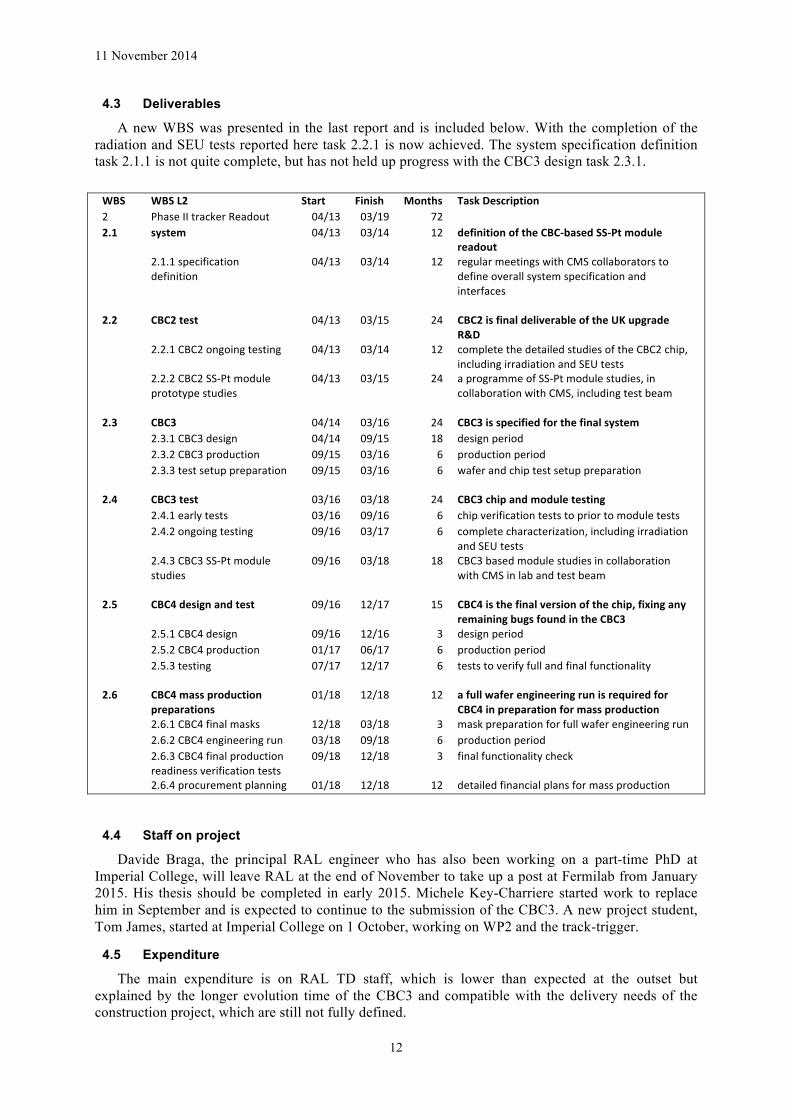
4.3 Deliverables
A new WBS was presented in the last report and is included below. With the completion of the radiation and SEU tests reported here task 2.2.1 is now achieved. The system specification definition task 2.1.1 is not quite complete, but has not held up progress with the CBC3 design task 2.3.1.
WBS WBS L2 Start Finish Months Task Description 2 Phase II tracker Readout 04/13 03/19 72 2.1 system 04/13 03/14 12 definition of the CBC-‐based SS-‐Pt module
readout 2.1.1 specification
definition 04/13 03/14 12 regular meetings with CMS collaborators to
define overall system specification and interfaces
2.2 CBC2 test 04/13 03/15 24 CBC2 is final deliverable of the UK upgrade R&D
2.2.1 CBC2 ongoing testing 04/13 03/14 12 complete the detailed studies of the CBC2 chip, including irradiation and SEU tests
2.2.2 CBC2 SS-‐Pt module prototype studies
04/13 03/15 24 a programme of SS-‐Pt module studies, in collaboration with CMS, including test beam
2.3 CBC3 04/14 03/16 24 CBC3 is specified for the final system 2.3.1 CBC3 design 04/14 09/15 18 design period 2.3.2 CBC3 production 09/15 03/16 6 production period 2.3.3 test setup preparation 09/15 03/16
6
wafer and chip test setup preparation
2.4 CBC3 test 03/16 03/18 24 CBC3 chip and module testing 2.4.1 early tests 03/16 09/16 6 chip verification tests to prior to module tests 2.4.2 ongoing testing 09/16 03/17 6 complete characterization, including irradiation
and SEU tests 2.4.3 CBC3 SS-‐Pt module
studies 09/16 03/18 18 CBC3 based module studies in collaboration
with CMS in lab and test beam
2.5 CBC4 design and test 09/16 12/17 15 CBC4 is the final version of the chip, fixing any remaining bugs found in the CBC3
2.5.1 CBC4 design 09/16 12/16 3 design period 2.5.2 CBC4 production 01/17 06/17 6 production period 2.5.3 testing 07/17 12/17 6
tests to verify full and final functionality
2.6 CBC4 mass production preparations
01/18 12/18 12 a full wafer engineering run is required for CBC4 in preparation for mass production
2.6.1 CBC4 final masks 12/18 03/18 3 mask preparation for full wafer engineering run 2.6.2 CBC4 engineering run 03/18 09/18 6 production period 2.6.3 CBC4 final production
readiness verification tests 09/18 12/18 3 final functionality check
2.6.4 procurement planning 01/18 12/18 12 detailed financial plans for mass production
4.4 Staff on project
Davide Braga, the principal RAL engineer who has also been working on a part-time PhD at Imperial College, will leave RAL at the end of November to take up a post at Fermilab from January 2015. His thesis should be completed in early 2015. Michele Key-Charriere started work to replace him in September and is expected to continue to the submission of the CBC3. A new project student, Tom James, started at Imperial College on 1 October, working on WP2 and the track-trigger.
4.5 Expenditure
The main expenditure is on RAL TD staff, which is lower than expected at the outset but explained by the longer evolution time of the CBC3 and compatible with the delivery needs of the construction project, which are still not fully defined.
11 November 2014
13
5. Work Package 3: Level-1 Trigger
5.1 Objectives
• Improvement of the current CMS calorimeter trigger in preparation for above-design-luminosity conditions.
• Provision of infrastructure to allow testing of an entirely new calorimeter trigger in parallel with the existing system.
• Design, construction and testing of a time-multiplexed hardware trigger for CMS, capable of implementing new and more selective algorithms.
• Design of a track trigger architecture for HL-LHC running, and construction of a technology demonstrator.
5.2 Progress to date
MP7 production of 32 cards was split between two companies to mitigate risk and because the two leading bids were within 3% of each other. The production at Hapro, Norway has proceeded smoothly and is finished. All cards have passed through a detailed set of power, interconnect and functional tests and most are now installed within the Underground Service Cavern next to CMS.
In both cases, the manufacture was staged into deliveries of 2 (A), 4 (B) and 10 (C) boards with approval from our side at each stage, following acceptance tests, to ensure quality and minimise risk.
The production at Exception-PCB, UK was deliberately delayed until the initial pre-series-A batch from Hapro had been validated. Production has been difficult, with some lack of communication, nicks in the gold coated edge connector, failed batches, low yield and an inability to follow the instructions carefully. The issues were raised with the CEO, Gordon Holden, on 1 August who immediately instigated a review, which led to improvements in the PCB manufacturing procedures and a change in contact person to Mike Devine (the Technical Director). We recently received the 2 cards for pre-series-A. Exception-PCB and Jaltek, the assembly subcontractor, both appear to be operating close to their technical limit. The PCB yield remains low at 30% and the assembly process required a lot of rework. Nonetheless, both cards have passed basic power & interconnect tests and one card has passed all the functional tests. The technical specification of the cards demanded the PCB quality met the highest standard available and thus the final PCBs delivered should be of high quality despite the yield issue.
A supplementary production of 8 cards has been ordered from Hapro using spare PCBs from the first production. A further order of 32 cards will be placed at Hapro to meet the needs of our collaborators shortly when funds are in place.
The infrastructure at CMS is almost complete, with PCs, crates, cards, power supplies and the L1-L2 full mesh patch panel all installed (see Fig. 5.1 and 5.2). It is the first time that this special type of patch panel has been installed in an experiment at CERN. It replaces a large, manually assembled patch panel with one routed internally by a robot. It occupies a fraction of the space or the original design and took a few hours to install rather than several months. Despite its rather basic appearance (Fig. 5.2) and simple functionality this patch panel will allow many more possibilities for future systems because it provides much more flexibility. The limited tests so far indicate that the patch panel is operating as expected. Full commissioning of the patch panel will take place over the next few weeks with the aim being to finish validation by 22 December 2014.

11 November 2014
14
Fig. 5.1 The provisional crate installed with 6 production MP7s. The final crate, due Nov 19th, will have redundant power modules mounted in the rear (currently top centre). The optics are not yet cabled up.
Fig. 5.2 The full mesh patch panel. It allows significant interconnect possibilities. The boxes shown here shuffle 288 fibres, but the technology used to construct them allows more than an order of magnitude more to be squeezed into the same space.
An integration test between the Layer-1 (U. Wisconsin) and Layer-2 (UK) electronics was performed in July and early August. Simple patterns and more complex simulated events were sent from the output buffers of a prototype CTP7 card to an MP7 card. The data was processed by the jets and energy sum algorithm firmware in the MP7 and the output captured and compared to the expectation from the software emulation of the algorithms. Extremely good agreement was observed
11 November 2014
15
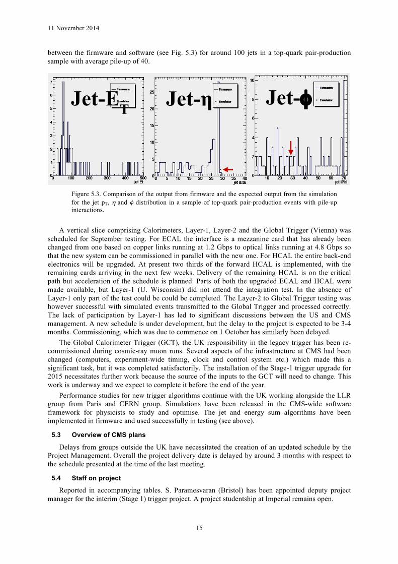
between the firmware and software (see Fig. 5.3) for around 100 jets in a top-quark pair-production sample with average pile-up of 40.
Figure 5.3. Comparison of the output from firmware and the expected output from the simulation for the jet pT, η and φ distribution in a sample of top-quark pair-production events with pile-up interactions.
A vertical slice comprising Calorimeters, Layer-1, Layer-2 and the Global Trigger (Vienna) was scheduled for September testing. For ECAL the interface is a mezzanine card that has already been changed from one based on copper links running at 1.2 Gbps to optical links running at 4.8 Gbps so that the new system can be commissioned in parallel with the new one. For HCAL the entire back-end electronics will be upgraded. At present two thirds of the forward HCAL is implemented, with the remaining cards arriving in the next few weeks. Delivery of the remaining HCAL is on the critical path but acceleration of the schedule is planned. Parts of both the upgraded ECAL and HCAL were made available, but Layer-1 (U. Wisconsin) did not attend the integration test. In the absence of Layer-1 only part of the test could be could be completed. The Layer-2 to Global Trigger testing was however successful with simulated events transmitted to the Global Trigger and processed correctly. The lack of participation by Layer-1 has led to significant discussions between the US and CMS management. A new schedule is under development, but the delay to the project is expected to be 3-4 months. Commissioning, which was due to commence on 1 October has similarly been delayed.
The Global Calorimeter Trigger (GCT), the UK responsibility in the legacy trigger has been re-commissioned during cosmic-ray muon runs. Several aspects of the infrastructure at CMS had been changed (computers, experiment-wide timing, clock and control system etc.) which made this a significant task, but it was completed satisfactorily. The installation of the Stage-1 trigger upgrade for 2015 necessitates further work because the source of the inputs to the GCT will need to change. This work is underway and we expect to complete it before the end of the year.
Performance studies for new trigger algorithms continue with the UK working alongside the LLR group from Paris and CERN group. Simulations have been released in the CMS-wide software framework for physicists to study and optimise. The jet and energy sum algorithms have been implemented in firmware and used successfully in testing (see above).
5.3 Overview of CMS plans
Delays from groups outside the UK have necessitated the creation of an updated schedule by the Project Management. Overall the project delivery date is delayed by around 3 months with respect to the schedule presented at the time of the last meeting.
5.4 Staff on project
Reported in accompanying tables. S. Paramesvaran (Bristol) has been appointed deputy project manager for the interim (Stage 1) trigger project. A project studentship at Imperial remains open.
Jet-ET Jet-η Jet-φ

11 November 2014
16
5.5 Expenditure
Most of the expenditure to date continues to be committed to MP7 manufacture and component purchases. Overall spending is well within the budget foreseen at this stage.
5.6 Deliverables
The deliverable list is appended below. Blue font means complete. Red font is delayed.
L1 L2
Start Finish PM Task description
3.1
Stage-‐1 calorimeter trigger upgrade 3.1.1 Hardware development 07/13 6 Finalisation of production hardware module (48-‐
link version) 3.1.2 Procurement and testing 07/13 10/13 3 Procurement, production and acceptance tests of
hardware 3.1.3 uTCA infrastructure 07/13 6 Completion of baseline IPbus / uHAL 3.1.4 Online software development 04/13 10/13 6 Development of system-‐specific and trigger-‐wide
online software (control, monitoring, DAQ) 3.1.5 Algorithms and offline software 04/13 04/14 12 Development of stage-‐1 algorithms and
corresponding emulator and DQM software 3.1.6 Integration 07/13 01/14 6 Integration tests with other trigger components,
DAQ, TTC 3.1.7 Commissioning 09/14 03/15 6 Commissioning with cosmics and beam 3.1.8 Support 03/15 01/16 9 Ongoing expert support and optimisation of
Stage-‐1 system 3.2 Stage-‐2 calorimeter trigger (TMT) upgrade 3.2.1 Hardware development 10/13 04/14 6 Development and finalisation of production
hardware module (72-‐link version) 3.2.2 Procurement and testing 04/14 10/14 6 Procurement, production and acceptance tests of
hardware 3.2.3 Online software development 10/13 04/14 6 Development of system-‐specific and trigger-‐wide
online software (control, monitoring, DAQ) 3.2.4 Algorithms and offline software 04/14 04/15 12 Development of stage-‐2 algorithms and
corresponding emulator and DQM software 3.2.5 Integration 04/14 10/14 6 Integration tests with other trigger components,
DAQ, TTC 3.2.6 Commissioning 04/15 04/16 12 Commissioning with cosmics and beam 3.2.7 Support 04/16 04/19 36 Ongoing expert support and optimisation of
stage-‐2 system 3.3 Post-‐LS3 trigger R&D 3.3.1 Design studies 04/13 10/14 18 Simulation studies of track trigger performance,
and decision on final concept 3.3.2 Dataflow design 10/14 10/15 12 Detailed simulation, architecture design and
technology choices for track trigger 3.3.3 Hardware development 04/16 10/17 18 Development of next-‐generation hardware
modules for integrated L1 trigger 3.3.4 Algorithms and offline software 10/15 04/17 18 Development of algorithms and firmware for
integrated L1 trigger 3.3.5 Integration and demonstration 10/17 10/18 12 Hardware slice test of integrated L1 trigger 3.3.6 Final system design 10/18 04/19 6 Production planning for final version of
integrated L1 trigger
Last time we reported concern about delivery of the Boston AMC13 module, which interfaces to the DAQ. This has been solved.
The work from the UK required for 3.1.4 has been provided and we consider our contributions to 3.1.5 to be delivered, although it is possible that further help will be requested next year. A major revision of the online software, with a substantial UK contribution is under way, so 3.2.3 is more extensive than planned.

11 November 2014
17
6 Risk register The risk register has been reviewed. No new risks have been identified, but several risks have been
revised, for both increased and decreased likelihood. Two risks have been retired. The overall picture shows no major cause for concern and, of the items where risk has increased they have already been the subject of considerable activity. UK funds are sufficient to address the issues of timely delivery.
The two main issues which are worthy of note are ASIC foundry access and US funding. The IBM foundry used for 130 nm CMOS manufacture has been sold recently to another owner
after being the subject of speculation in the trade press for some time. However, it was confirmed at the same time that MOSIS MPW and dedicated services for IBM processes will continue to be available to MOSIS users.
“GLOBALFOUNDRIES will acquire and operate existing IBM semiconductor manufacturing operations and facilities in East Fishkill, New York and Essex Junction, Vermont, adding capacity to serve its customers and thousands of jobs to GLOBALFOUNDRIES’ workforce.”
http://www-03.ibm.com/press/us/en/pressrelease/45110.wss The new owner is a substantial company and MOSIS, who depend on this foundry, have visited
CERN in the last few months and have assured us that access will continue. On the basis of these discussions, both CMS and ATLAS decided to continue to use the process for their outer tracker ASICs. The alternative would have been to transfer the designs to TSMC, which is the subject of a new foundry contract for 65 nm CMOS but, after assessment of the options, to continue with the same process seemed most attractive.
US funding for the upgrade projects has been limited for some time and subject to the traditional US DOE procedures, involving Conceptual Design (CD) approval stages. The US had to decide where to apply their operations budget while the approval process was under way and were guided by CMS management that the pixel project should be given the highest priority, along with completion of the muon system, while HCAL and trigger projects should be managed with a lower priority. This has an impact on the trigger project, but within CMS was believed to be tolerable. CMS has also tried to help the US manage their cash flow to ensure the delivery of crucial components, such as the HCAL µHTR boards.
It is now expected that the delivery of the HCAL µHTRs will be completed during early next year, after successful manufacture of the boards for the HF. Therefore this is not seen as a major risk to the delivery of the Phase I trigger upgrade.
There has been an impact from the availability of funding for the Layer-1 of the calorimeter trigger project which has slowed the delivery of the CTP7 boards and associated infrastructure. However, technical progress with the US trigger boards, both for Stage-1 and the TDR triggers, was also slower than anticipated, which has generated some difficulties. The recently appointed Trigger co-Project Manager, Costas Foudas, was tasked with addressing the challenges and has been working intensively to do so since taking up his position in January, with a plan developed in March. This plan has been the subject of several revisions, and increasing interest and support from the CMS Spokesperson team.
The latest plan still foresees completion of the TDR trigger by August 2015, so it can be commissioned for operation in 2016 and the CMS management has made clear the importance of this objective.
7 Finances Expenditure is reported in the usual financial table. The reported travel expenditure is lower than
actual because of the normal delays in universities invoicing SBS, but expenditure is actually anticipated to increase in the second half of the year because of extra LTA commitments, including some late charging for a RAL LTA, for which corrections are expected soon.
Most of the expenditure relates to the production of MP7 and FC7 boards and infrastructure for the new trigger system, such as crates, optical transceivers, fibres, patch panels and other minor

11 November 2014
18
components. The total given in the table only shows part of the picture since much of this expenditure has been via CERN and invoices have yet to arrive. Some of them have arrived recently and others are expected when the two present orders for MP7s are complete.
The two 16 board MP7 orders amount to 290kCHF, which does not include the optical transceiver, which represent about an additional 50%. Further commitments in CERN amount to 168 kCHF, of which 137 kCHF have recently been invoiced but not yet received at Imperial College. Earlier orders which were paid using the CERN UK CMS team account and charged back to Imperial amount to approximately £58k. RAL equipment expenditure this year is slightly higher than expected because some procurements were made via SBS, and a way has to be found to charge this to Imperial College where the equipment budget is held. Overall the total expenditure to date, including commitments, amounts to approximately £400k, to be compared to the £2.2M allocation.
Commitments for the next ASIC submission are now not expected until late 2015, so the purchasing commitments are proceeding more slowly than originally anticipated but this simply reflects delays in overall HL-LHC planning. Meanwhile engineering expenditure at RAL is broadly in line with the plan but we are endeavouring to proceed with caution, in case of possible specification changes, since, although these now seem unlikely, discussions are still under way regarding issues of trigger rates, latency, data bandwidth etc. We wish to preserve our engineering staff budget at a reasonable level to cope with this uncertainty.
We believe we have solved the problem of purchasing via CERN and invoicing Imperial College, with the aid of the CMS resource management team. It is actually not so clear at present how best to arrange invoicing within the UK, although it should be possible if required.
8 Gantt charts The most recent Gantt chart for the trigger project is again included. There is no further update on
the Phase II tracker planning.

11 November 2014
19
9 Milestones The deliverables from each work package are listed below. The milestones which were due have
been highlighted in red font, or those met in blue. A new column has been added to the table for revised milestone dates and some of the deliverables are highlighted, with supplementary commentary below.
Deliverable Date Description Rev.Date M2.1 PM12 System specification document produced PM12 M2.2.1 PM12 Documented CBC2 detailed test results PM12 M2.2.2 PM24 Documented 2S-‐Pt module results PM24 M2.3.1 PM12 CBC3 ready for production PM30 M2.3.2 PM18 CBC3 produced & test setups ready PM36 M2.4.1 PM24 Documented early CBC3 test results PM42 M2.4.2 PM30 Documented CBC3 detailed test results PM48 M2.4.3 PM60 Documented CBC3 2S-‐Pt module results PM60 M2.5.1 PM42 CBC4 ready for production PM45 M2.5.2 PM48 CBC4 produced PM51 M2.5.3 PM54 Documented CBC4 test results PM57 M2.6.1 PM60 Final production masks prepared PM60 M2.6.3 PM69 CBC4 ready for mass production PM69 M2.7.3 PM72 First production modules available PM72
M3.1 PM9 Stage-‐1 calorimeter trigger hardware tested and installed PM21 M3.2 PM18 Stage-‐2 calorimeter trigger hardware tested and installed PM28 M3.3 PM23 Stage-‐1 calorimeter trigger commissioned & system ready for physics PM27 M3.4 PM30 Post-‐LS3 trigger dataflow design completed PM30 M3.5 PM35 Stage-‐2 calorimeter trigger commissioned & system ready for physics PM35 M3.6 PM54 Post-‐LS3 trigger prototype trigger modules produced and tested PM54 M3.7 PM66 Demonstration of post-‐LS3 trigger slice PM66 M3.8 PM72 Post-‐LS3 trigger construction plan delivered PM72
The milestones for WP2 essentially reflect progress with the overall tracker (and CMS) HL-LHC
upgrade with the planning uncertainties described earlier. Therefore adjustments are not the result of delays in the UK activities or technical difficulties but reflect additional work or evolution of the CMS specifications following from physics and detector studies.
As mentioned in the last report, Milestone 2.1 is not fully complete but is tied to the overall CMS and LHC schedule; however there are many internal documents, and the CMS Technical Proposal in September, now delayed a further six months, was expected to allow to sign this off. Milestone 2.2.1 is complete. The CBC3 design and manufacture are delayed as a consequence of increased requirements, and the time thought to be available.
The WP3 milestones, however, do reflect genuine delays, most of which are a consequence of difficulties on the US side. They are a concern in view of trigger operation in 2015, although only to a limited extent, but more so in 2016. Both the UK project managers, and the CMS trigger management and Spokesperson team are taking a very close interest in developments, with increasing attention to ensure that the TDR trigger will be delivered on time for 2016 operation.
The legacy (RCT-GCT-GT) trigger will be sufficient for 2015 operation, given what is envisaged for the luminosity, with the exception of the heavy ion running, for which an improved jet trigger in particular is essential. Therefore, an operational Stage-1 trigger in August 2015 would be sufficient to be confident to have a well commissioned trigger for HI operation in December. Stage-1 could, in the trigger planning, be ready for parallel operation with the legacy trigger by April 2015, and it is assumed parallel running would be necessary before it is considered qualified for data taking. It might

11 November 2014
20
therefore be ready for physics by the time of 25 ns operation in July 2015, which is what is assumed in the table above.
The TDR trigger, based on the TMT, is in almost all respects now ahead of the Stage-1 trigger. However, the TDR trigger requires new hardware upstream of the trigger, which will not be available until mid-2015; final commissioning of the TDR trigger of course requires all the hardware. Layer-2, the UK part, is essentially complete including well developed algorithm firmware and emulation, but Layer-1 is not yet present. A crate and several pre-production CTP7 boards were installed at Point 5 in the first week of November. A hard deadline is proposed for sufficient Layer-1 hardware to be ready in January 2015, or an alternative plan will be invoked. Beyond that, the other major uncertainty for 2016 trigger operation is the full availability of the HCAL µHTR cards, which generate the HCAL trigger primitives, another US responsibility. This has been the subject of action by CMS to ensure funds are in place so that deliveries and commissioning are completed in a timely way.