
Updates on Operational Processing of ATMS TDR and … · Updates on Operational Processing of ATMS...
22
Updates on Operational Processing of ATMS TDR and SDR Products Fuzhong Weng Satellite Meteorology and Climatology Division Center for Satellite Applications and Research National Environmental Satellites, Data and Information Service National Oceanic and Atmospheric Administration (NOAA)
Transcript of Updates on Operational Processing of ATMS TDR and … · Updates on Operational Processing of ATMS...
Updates on Operational Processing of ATMS TDR and SDR Products Fuzhong Weng
Satellite Meteorology and Climatology Division Center for Satellite Applications and Research National Environmental Satellites, Data and Information Service National Oceanic and Atmospheric Administration (NOAA)
Outline
• ATMS Instrument Characterization
• ATMS in-orbit Performance Status
• Advanced ATMS SDR Sciences and Algorithms
• Upcoming Changes in ATMS TDR/SDR Processing
• Summary and Conclusions
2
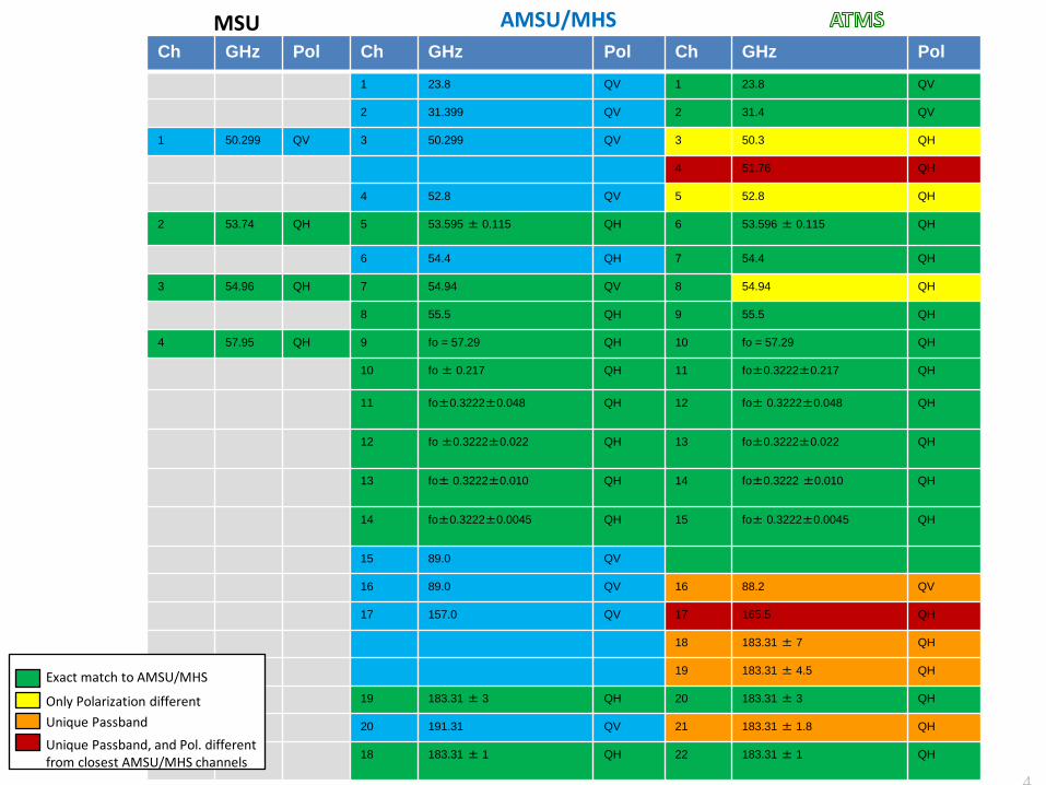
Ch GHz Pol Ch GHz Pol Ch GHz Pol
1 23.8 QV 1 23.8 QV
2 31.399 QV 2 31.4 QV
1 50.299 QV 3 50.299 QV 3 50.3 QH
4 51.76 QH
4 52.8 QV 5 52.8 QH
2 53.74 QH 5 53.595 ± 0.115 QH 6 53.596 ± 0.115 QH
6 54.4 QH 7 54.4 QH
3 54.96 QH 7 54.94 QV 8 54.94 QH
8 55.5 QH 9 55.5 QH
4 57.95 QH 9 fo = 57.29 QH 10 fo = 57.29 QH
10 fo ± 0.217 QH 11 fo±0.3222±0.217 QH
11 fo±0.3222±0.048 QH 12 fo± 0.3222±0.048 QH
12 fo ±0.3222±0.022 QH 13 fo±0.3222±0.022 QH
13 fo± 0.3222±0.010 QH 14 fo±0.3222 ±0.010 QH
14 fo±0.3222±0.0045 QH 15 fo± 0.3222±0.0045 QH
15 89.0 QV
16 89.0 QV 16 88.2 QV
17 157.0 QV 17 165.5 QH
18 183.31 ± 7 QH
19 183.31 ± 4.5 QH
19 183.31 ± 3 QH 20 183.31 ± 3 QH
20 191.31 QV 21 183.31 ± 1.8 QH
18 183.31 ± 1
QH 22 183.31 ± 1 QH
Exact match to AMSU/MHS
Only Polarization different Unique Passband Unique Passband, and Pol. different from closest AMSU/MHS channels
AMSU/MHS
4
MSU
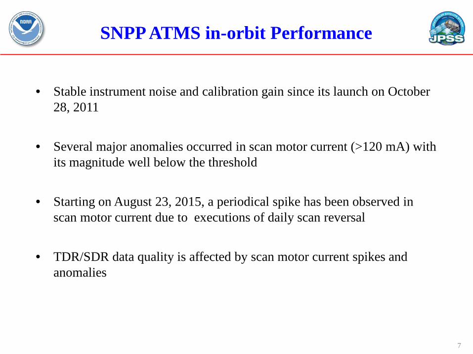
SNPP ATMS in-orbit Performance
• Stable instrument noise and calibration gain since its launch on October 28, 2011
• Several major anomalies occurred in scan motor current (>120 mA) with its magnitude well below the threshold
• Starting on August 23, 2015, a periodical spike has been observed in scan motor current due to executions of daily scan reversal
• TDR/SDR data quality is affected by scan motor current spikes and anomalies
7
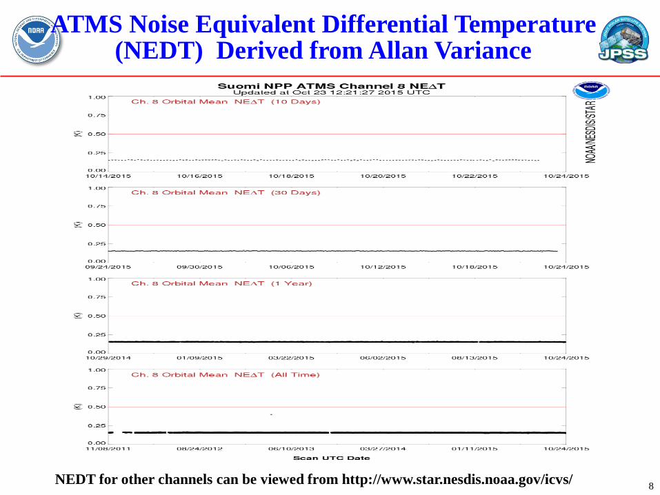
ATMS Noise Equivalent Differential Temperature (NEDT) Derived from Allan Variance
8 NEDT for other channels can be viewed from http://www.star.nesdis.noaa.gov/icvs/
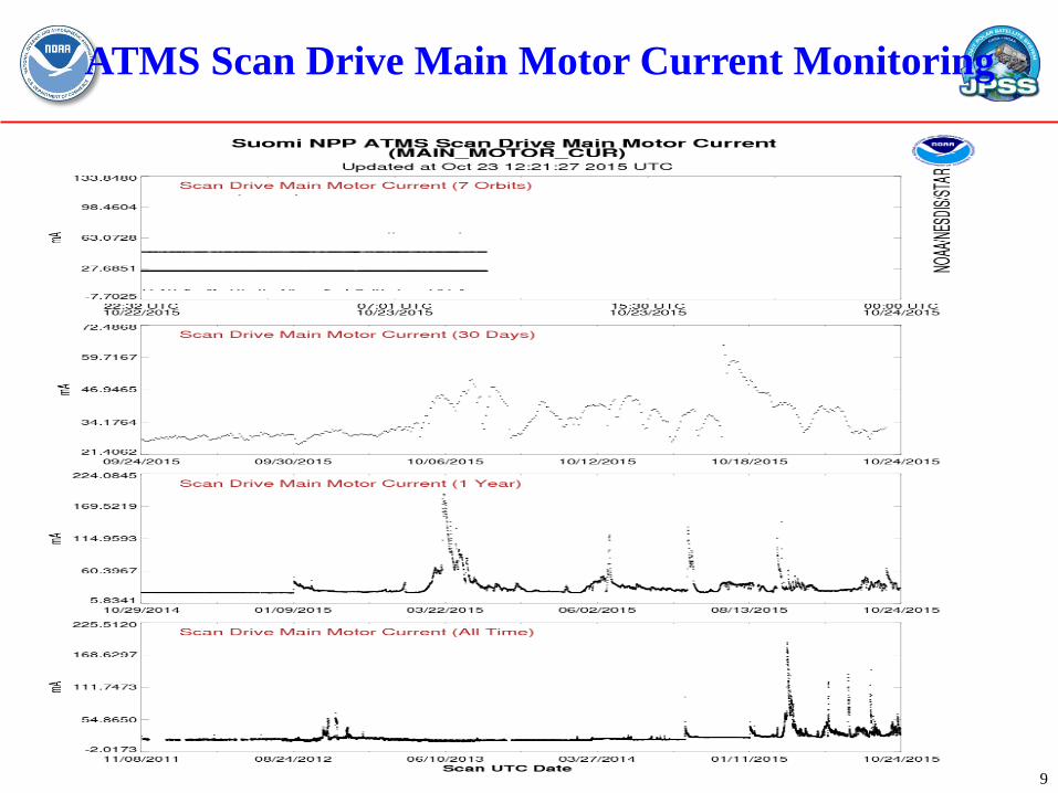
ATMS Scan Drive Main Motor Current Monitoring
9
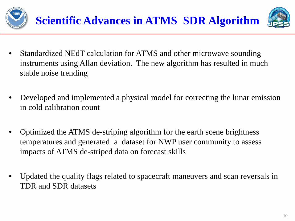
Scientific Advances in ATMS SDR Algorithm
• Standardized NEdT calculation for ATMS and other microwave sounding instruments using Allan deviation. The new algorithm has resulted in much stable noise trending
• Developed and implemented a physical model for correcting the lunar emission in cold calibration count
• Optimized the ATMS de-striping algorithm for the earth scene brightness temperatures and generated a dataset for NWP user community to assess impacts of ATMS de-striped data on forecast skills
• Updated the quality flags related to spacecraft maneuvers and scan reversals in TDR and SDR datasets
10
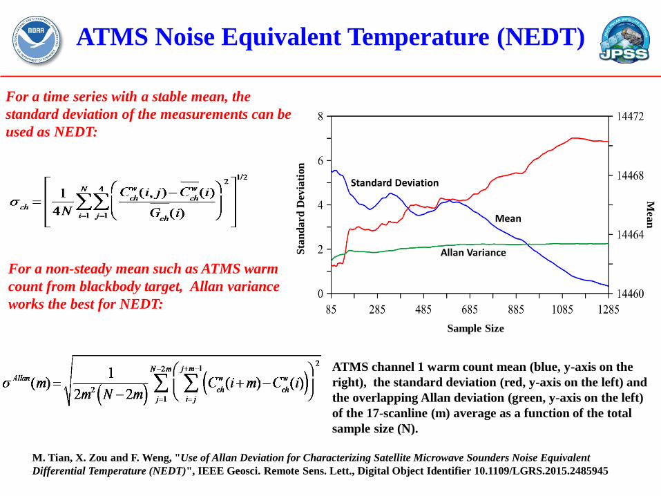
ATMS Noise Equivalent Temperature (NEDT)
For a time series with a stable mean, the standard deviation of the measurements can be used as NEDT:
For a non-steady mean such as ATMS warm count from blackbody target, Allan variance works the best for NEDT:
ATMS channel 1 warm count mean (blue, y-axis on the right), the standard deviation (red, y-axis on the left) and the overlapping Allan deviation (green, y-axis on the left) of the 17-scanline (m) average as a function of the total sample size (N).
Sample Size
Stan
dard
Dev
iatio
n
Mean
M. Tian, X. Zou and F. Weng, "Use of Allan Deviation for Characterizing Satellite Microwave Sounders Noise Equivalent Differential Temperature (NEDT)", IEEE Geosci. Remote Sens. Lett., Digital Object Identifier 10.1109/LGRS.2015.2485945
Mean
Allan Variance
Standard Deviation
ATMS Noise Equivalent Temperature (NEDT)
Channel Number
Stan
dard
/Alla
n De
viat
ion
(K)
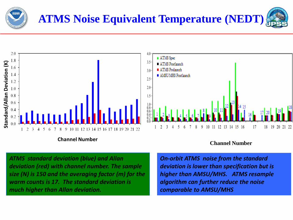
ATMS standard deviation (blue) and Allan deviation (red) with channel number. The sample size (N) is 150 and the averaging factor (m) for the warm counts is 17. The standard deviation is much higher than Allan deviation.
Channel Number
On-orbit ATMS noise from the standard deviation is lower than specification but is higher than AMSU/MHS. ATMS resample algorithm can further reduce the noise comparable to AMSU/MHS
Without LI correction
With LI correction
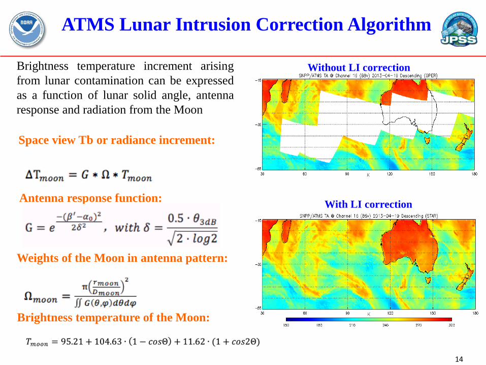
ATMS Lunar Intrusion Correction Algorithm
14
Brightness temperature increment arising from lunar contamination can be expressed as a function of lunar solid angle, antenna response and radiation from the Moon
Space view Tb or radiance increment:
Antenna response function:
Weights of the Moon in antenna pattern:
Brightness temperature of the Moon:

Impacts of ATMS Striping Effects on Channel Noise Characterization
16
• Channel noise reduced after applying striping mitigation algorithm
• 45-day de-striping BUFR data generated for NWP impact study
Qin, Z., X. Zou and F. Weng, 2013: Analysis of ATMS and AMSU striping noise from their earth scene observations. J. Geophy. Res., 118, 13,214-13,229, doi: 10.1002/ 2013JD020399 Ma, Y. and X. Zou, 2015: Optimal filters for striping noise mitigation within ATMS calibration counts. IEEE Trans. Geo. Remote Sensing, (in revision)
Upcoming Changes in ATMS SDR Processing
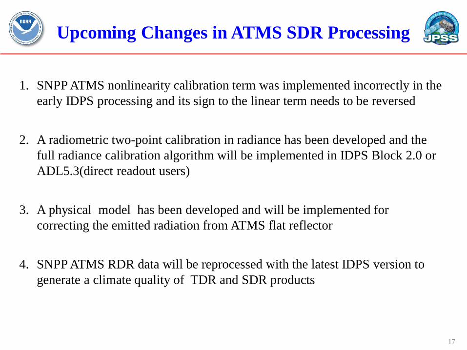
1. SNPP ATMS nonlinearity calibration term was implemented incorrectly in the early IDPS processing and its sign to the linear term needs to be reversed
2. A radiometric two-point calibration in radiance has been developed and the full radiance calibration algorithm will be implemented in IDPS Block 2.0 or ADL5.3(direct readout users)
3. A physical model has been developed and will be implemented for correcting the emitted radiation from ATMS flat reflector
4. SNPP ATMS RDR data will be reprocessed with the latest IDPS version to generate a climate quality of TDR and SDR products
17
Global Mean O-B Bias from ATMS Full Radiance Calibration
-1
-0.5
0
0.5
1
1.5
2
2.5
3
3.5
1 2 3 4 5 6 7 8 9 10 11 12 13 14 15 16 17 18 19 20 21 22
TDR
- RTM
Bia
s [K]
Channels
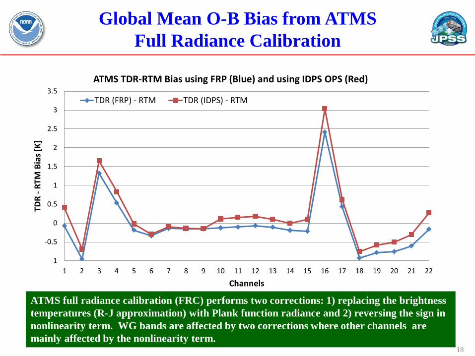
ATMS TDR-RTM Bias using FRP (Blue) and using IDPS OPS (Red)
TDR (FRP) - RTM TDR (IDPS) - RTM
ATMS full radiance calibration (FRC) performs two corrections: 1) replacing the brightness temperatures (R-J approximation) with Plank function radiance and 2) reversing the sign in nonlinearity term. WG bands are affected by two corrections where other channels are mainly affected by the nonlinearity term.
18
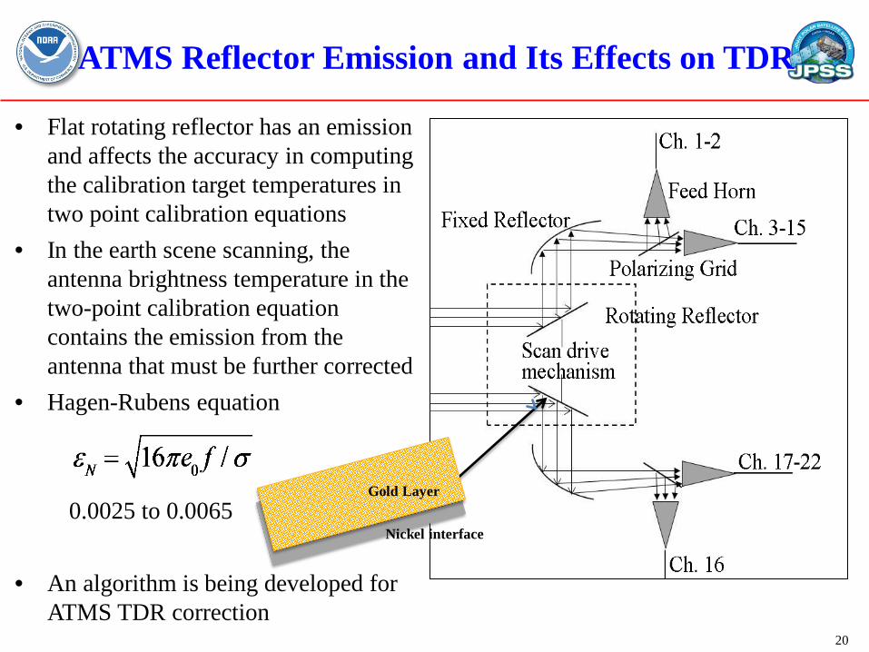
ATMS Reflector Emission and Its Effects on TDR
• Flat rotating reflector has an emission and affects the accuracy in computing the calibration target temperatures in two point calibration equations
• In the earth scene scanning, the antenna brightness temperature in the two-point calibration equation contains the emission from the antenna that must be further corrected
• Hagen-Rubens equation
0.0025 to 0.0065
• An algorithm is being developed for
ATMS TDR correction 20
Gold Layer
Nickel interface
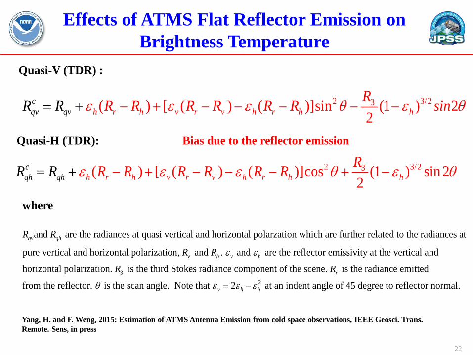
Effects of ATMS Flat Reflector Emission on Brightness Temperature
Quasi-V (TDR) :
Quasi-H (TDR):
2 3/23( ) [ ( ) ( )]sin (1 ) 22h r h v r v h
cqv h hq rv
RR R R R nR R iR R sε ε ε θ ε θ− + − − − −= −+
2 3/23( ) [ ( ) ( )]cos (1 ) sin 22h r h v r v h
cqh q r h hh
RR RR R R R RR ε ε ε θ ε θ= − + − − − + −+
Bias due to the reflector emission
Yang, H. and F. Weng, 2015: Estimation of ATMS Antenna Emission from cold space observations, IEEE Geosci. Trans. Remote. Sens, in press
22
where
and are the radiances at quasi vertical and horizontal polarzation which are further related to the radiances at
pure vertical and horizontal polarization, and . and are the reflectoqv qh
v h v h
R R
R R ε ε
3
r emissivity at the vertical and
horizontal polarization. is the third Stokes radiance component of the scene. is the radiance emitted
from the reflector. is the scan angle. Note that 2r
v h
R Rθ ε ε ε= − 2 at an indent angle of 45 degree to reflector normal.h
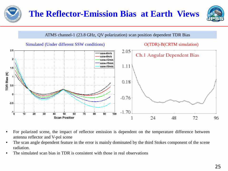
• For polarized scene, the impact of reflector emission is dependent on the temperature difference between antenna reflector and V-pol scene
• The scan angle dependent feature in the error is mainly dominated by the third Stokes component of the scene radiation.
• The simulated scan bias in TDR is consistent with those in real observations
ATMS channel-1 (23.8 GHz, QV polarization) scan position dependent TDR Bias
Simulated (Under different SSW conditions) O(TDR)-B(CRTM simulation)
The Reflector-Emission Bias at Earth Views
25
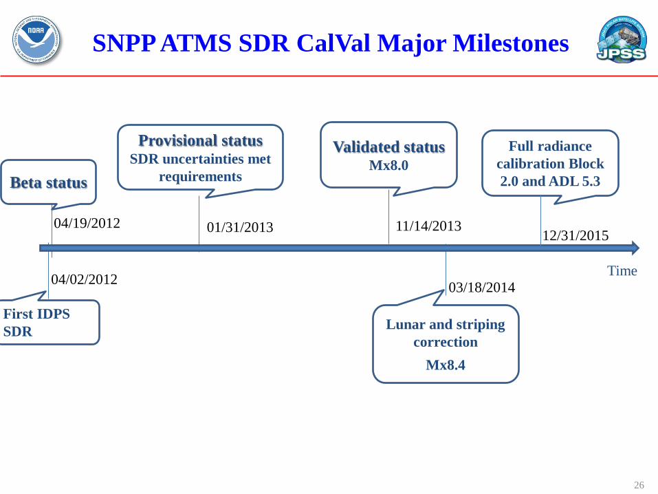
SNPP ATMS SDR CalVal Major Milestones
26
11/14/2013
Time
01/31/2013
Provisional status SDR uncertainties met
requirements Beta status
First IDPS SDR
Validated status Mx8.0
Lunar and striping correction
Mx8.4
03/18/2014
04/19/2012
04/02/2012
Full radiance calibration Block 2.0 and ADL 5.3
12/31/2015
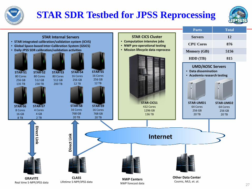
STAR SDR Testbed for JPSS Reprocessing
STAR-CICS1 432 Cores 1296 GB 136 TB
STAR CICS Cluster • Computation intensive jobs • NWP pre-operational testing • Mission lifecycle data reprocess
Internet
GRAVITE Real time S-NPP/JPSS data
CLASS Lifetime S-NPP/JPSS data
Direct Link
Dire
ct L
ink
STAR Internal Servers • STAR integrated calibration/validation system (ICVS) • Global Space-based Inter-Calibration System (GSICS) • Daily JPSS SDR calibration/validation activities
STAR-S1 80 Cores 256 GB 135 TB
STAR-S2 80 Cores 512 GB 230 TB
STAR-S4 16 Cores 256 GB 12 TB
STAR-S3 80 Cores 512 GB 200 TB
STAR-S5 16 Cores 256 GB 12 TB
STAR-S6 8 Cores 16 GB 8 TB
STAR-S7 4 Cores
4 GB 2 TB
STAR-S8 16 Cores 768 GB 20 TB
STAR-S9 16 Cores 768 GB 20 TB
STAR-UMD2 64 Cores 256 GB 20 TB
UMD/AOSC Servers • Data dissemination • Academia research testing
STAR-UMD1 64 Cores 256 GB 20 TB
NWP Centers NWP forecast data
Other Data Center Cosmic, MLS, et. al.
Parts Total
Servers 12
CPU Cores 876
Memory (GB) 5156
HDD (TB) 815
27
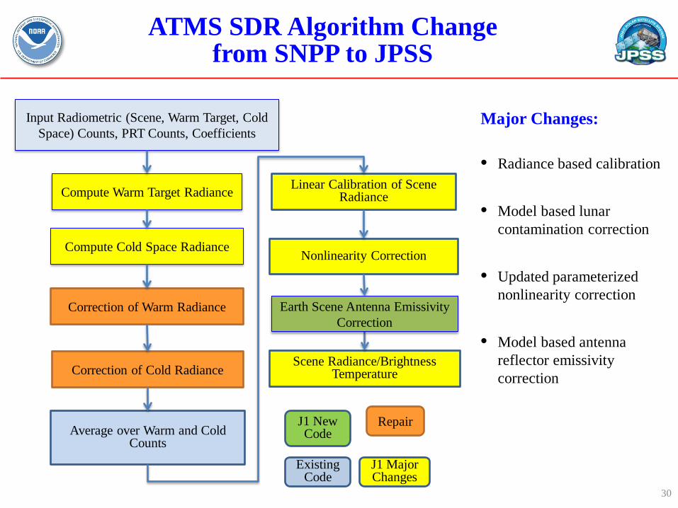
ATMS SDR Algorithm Change from SNPP to JPSS
Input Radiometric (Scene, Warm Target, Cold Space) Counts, PRT Counts, Coefficients
Compute Warm Target Radiance
Correction of Warm Radiance
Compute Cold Space Radiance
Correction of Cold Radiance
Average over Warm and Cold Counts
Linear Calibration of Scene Radiance
Nonlinearity Correction
Scene Radiance/Brightness Temperature
Major Changes:
• Radiance based calibration
• Model based lunar contamination correction
• Updated parameterized nonlinearity correction
• Model based antenna reflector emissivity correction
Earth Scene Antenna Emissivity Correction
30
J1 New Code
J1 Major Changes
Repair
Existing Code
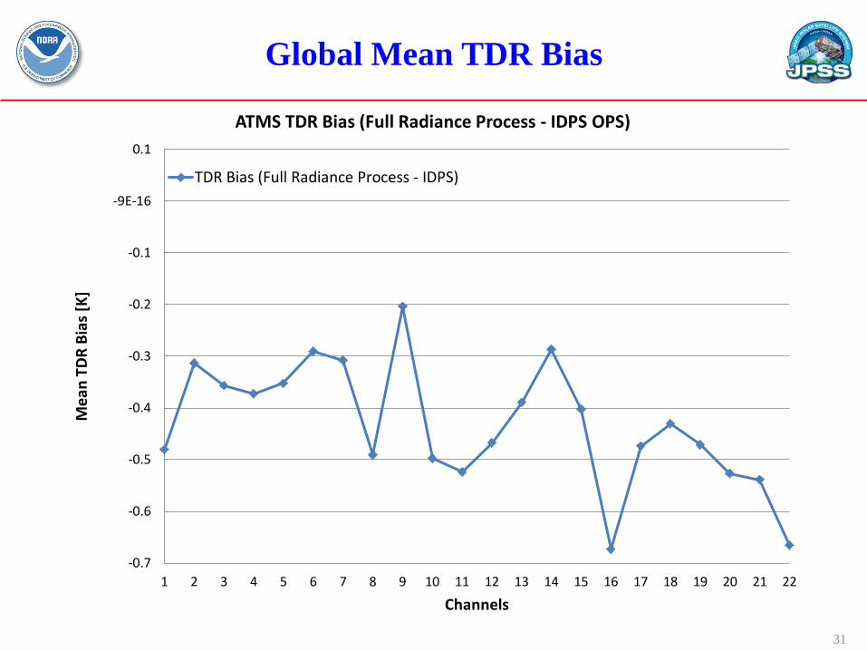
Global Mean TDR Bias
-0.7
-0.6
-0.5
-0.4
-0.3
-0.2
-0.1
-9E-16
0.1
1 2 3 4 5 6 7 8 9 10 11 12 13 14 15 16 17 18 19 20 21 22
Mea
n TD
R Bi
as [K
]
Channels
ATMS TDR Bias (Full Radiance Process - IDPS OPS)
TDR Bias (Full Radiance Process - IDPS)
31
32
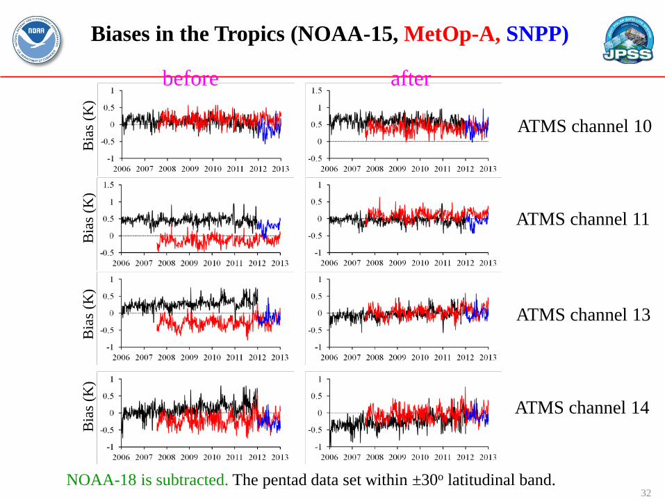
Biases in the Tropics (NOAA-15, MetOp-A, SNPP)
before after
ATMS channel 10
ATMS channel 11
ATMS channel 13
ATMS channel 14
Bia
s (K
) B
ias (
K)
Bia
s (K
) B
ias (
K)
NOAA-18 is subtracted. The pentad data set within ±30o latitudinal band.
Summary and Conclusions
• ATMS on-orbit NEDT is well characterized by new Allan deviation method, resulting in much lower NEDT values
• ATMS scan motor has been commanded for one reversal every 14 orbits for the purpose of extending its design life beyond 5 years
• ATMS full radiance calibration algorithm has been developed and will be implemented into IDPS Block 2.0
• ATMS flat reflector emission is fully characterized by using a physical model and pitch-over maneuver data. The algorithm for correcting this emission is ready for implementation into IDPS processing system
• ATMS O-B bias can be fully characterized if a full polarimetric RT model is used in simulation. The third Stokes component contributes to the simulated radiance in quasi-V and quasi-H channels
• J1 ATMS went through rework and V-band IF receiver and WG band video components were replaced with new parts. ATMS SDR science team is currently analyzing the TVAC data
33