Update on Crab Cavity: Impedance (at fundamental), RF noise, operational scenario
30
Update on Crab Cavity: Impedance (at fundamental), RF noise, operational scenario P. Baudrenghien, R. Calaga, T. Mastoridis March 21 st, 2014 25th HiLumi WP2 Meeting 1
-
Upload
todd-hinton -
Category
Documents
-
view
35 -
download
0
description
Update on Crab Cavity: Impedance (at fundamental), RF noise, operational scenario. P. Baudrenghien, R. Calaga, T. Mastoridis. Tolerable beam offset. RF Power vs. Q L for various RF voltages and beam offsets. - PowerPoint PPT Presentation
Transcript of Update on Crab Cavity: Impedance (at fundamental), RF noise, operational scenario
Update on Crab Cavity:Impedance (at fundamental), RF noise, operational scenario
P. Baudrenghien, R. Calaga, T. Mastoridis
March 21 st, 201425th HiLumi WP2 Meeting1
Tolerable beam offset
March 21 st, 201425th HiLumi WP2 Meeting2
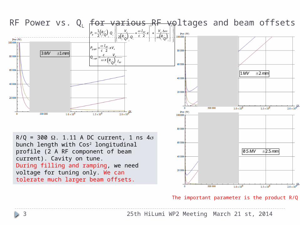
RF Power vs. QL for various RF voltages and beam offsets
March 21 st, 201425th HiLumi WP2 Meeting
R/Q = 300 W. 1.11 A DC current, 1 ns 4s bunch length with Cos2 longitudinal profile (2 A RF component of beam current). Cavity on tune. During filling and ramping, we need voltage for tuning only. We can tolerate much larger beam offsets.
3
2 2
,
,
1
2 22
2
L
L
x RF xg
RFg opt x
xL opt
RF
V I VRP Q xQ cR RQQ Q
IP xV
cc V
Qx R IQ
3 1MV mm
1 2MV mm
0.5 2.5MV mm
The important parameter is the product R/Q QL
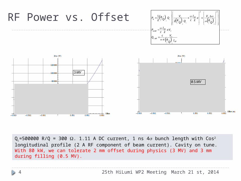
RF Power vs. Offset
March 21 st, 201425th HiLumi WP2 Meeting
QL=500000 R/Q = 300 W. 1.11 A DC current, 1 ns 4s bunch length with Cos2 longitudinal profile (2 A RF component of beam current). Cavity on tune. With 80 kW, we can tolerate 2 mm offset during physics (3 MV) and 3 mm during filling (0.5 MV).
4
2 2
,
,
1
2 22
2
L
L
x RF xg
RFg opt x
xL opt
RF
V I VRP Q xQ cR RQQ Q
IP xV
cc V
Qx R IQ
3 MV
0.5 MV
Impedance issues, fundamental mode
Case 1: Idling cavity (RF OFF)
March 21 st, 201425th HiLumi WP2 Meeting5

25th HiLumi WP2 Meeting
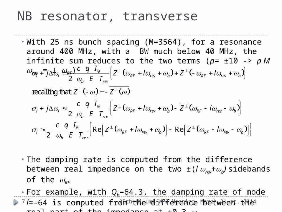
NB resonator, transverse
Transverse impedance of a transverse mode
The damping rate and tune shift of coupled-bunch mode l (rigid dipole only) can be computed from the cavity impedance
With w=(p M+l) wrev+wb.
1
sr
r
r
RZ
jQ
0
2l lpb rev
c q Ij Z
E T
March 21 st, 20146
25th HiLumi WP2 Meeting
• With 25 ns bunch spacing (M=3564), for a resonance around 400 MHz, with a BW much below 40 MHz, the infinite sum reduces to the two terms (p= ±10 -> p M wrev = ± wRF)
• The damping rate is computed from the difference between real impedance on the two ±(l wrev+wb) sidebands of the wRF
• For example, with Qb=64.3, the damping rate of mode l=-64 is computed from the difference between the real part of the impedance at ±0.3 wrev
• Negative damping rate -> instability
NB resonator, transverse
0
0
0
2
recalling that
2
Re Re2
l l RF rev b RF rev bb rev
l l RF rev b RF rev bb rev
l RF rev b RF rev bb rev
c q Ij Z l Z l
E T
Z Z
c q Ij Z l Z l
E T
c q IZ l Z l
E T
March 21 st, 20147
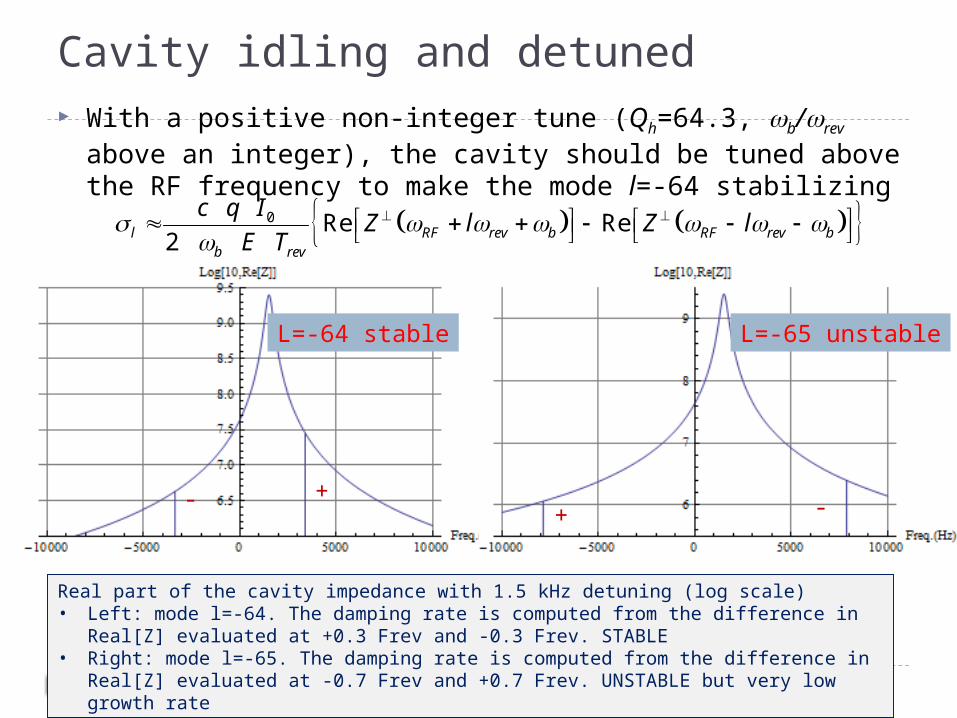
Cavity idling and detuned With a positive non-integer tune (Qh=64.3, wb/wrev above an
integer), the cavity should be tuned above the RF frequency to make the mode l=-64 stabilizing
March 21 st, 201425th HiLumi WP2 Meeting8
+-+ -
0 Re Re2l RF rev b RF rev b
b rev
c q IZ l Z l
E T
Real part of the cavity impedance with 1.5 kHz detuning (log scale)• Left: mode l=-64. The damping rate is computed from the difference in Real[Z]
evaluated at +0.3 Frev and -0.3 Frev. STABLE• Right: mode l=-65. The damping rate is computed from the difference in Real[Z]
evaluated at -0.7 Frev and +0.7 Frev. UNSTABLE but very low growth rate
L=-64 stable L=-65 unstable
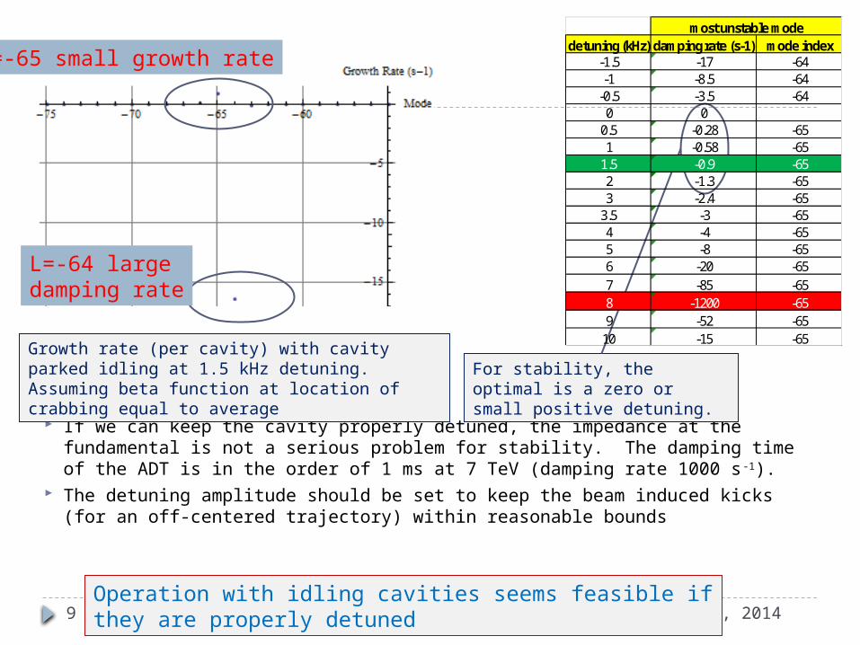
If we can keep the cavity properly detuned, the impedance at the fundamental is not a serious problem for stability. The damping time of the ADT is in the order of 1 ms at 7 TeV (damping rate 1000 s-1).
The detuning amplitude should be set to keep the beam induced kicks (for an off-centered trajectory) within reasonable bounds
March 21 st, 201425th HiLumi WP2 Meeting9
Growth rate (per cavity) with cavity parked idling at 1.5 kHz detuning. Assuming beta function at location of crabbing equal to average
detuning (kHz) damping rate (s-1) mode index-1.5 -17 -64-1 -8.5 -64-0.5 -3.5 -640 00.5 -0.28 -651 -0.58 -651.5 -0.9 -652 -1.3 -653 -2.4 -653.5 -3 -654 -4 -655 -8 -656 -20 -657 -85 -658 -1200 -659 -52 -6510 -15 -65
most unstable mode
Operation with idling cavities seems feasible if they are properly detuned
L=-64 large damping rate
L=-65 small growth rate
For stability, the optimal is a zero or small positive detuning.
Impedance issues, fundamental mode
Case 2: RF feedback ON
March 21 st, 201425th HiLumi WP2 Meeting10
RF ON
March 21 st, 201425th HiLumi WP2 Meeting
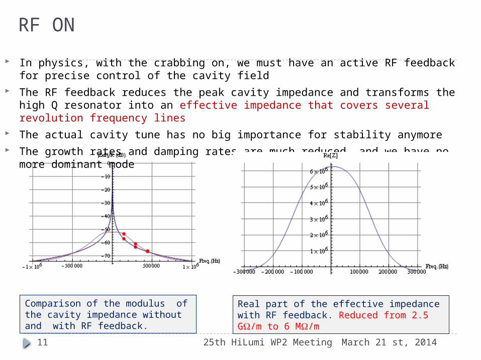
In physics, with the crabbing on, we must have an active RF feedback for precise control of the cavity field
The RF feedback reduces the peak cavity impedance and transforms the high Q resonator into an effective impedance that covers several revolution frequency lines
The actual cavity tune has no big importance for stability anymore The growth rates and damping rates are much reduced, and we have no more
dominant mode
Comparison of the modulus of the cavity impedance without and with RF feedback.
11
Real part of the effective impedance with RF feedback. Reduced from 2.5 GW/m to 6 MW/m
March 21 st, 201425th HiLumi WP2 Meeting12
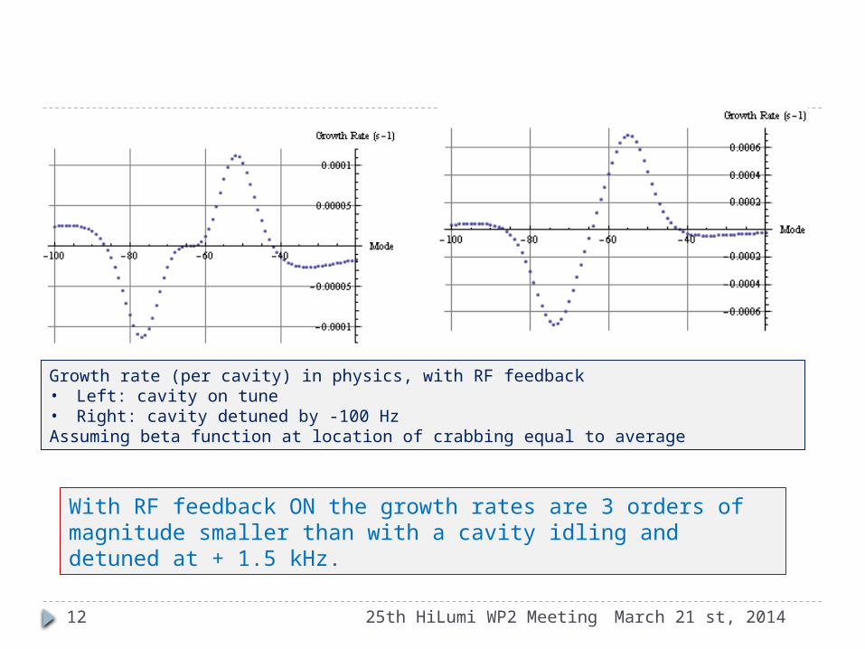
Growth rate (per cavity) in physics, with RF feedback• Left: cavity on tune• Right: cavity detuned by -100 HzAssuming beta function at location of crabbing equal to average
With RF feedback ON the growth rates are 3 orders of magnitude smaller than with a cavity idling and detuned at + 1.5 kHz.
Tentative conclusion (impedance at the fundamental) 1/2
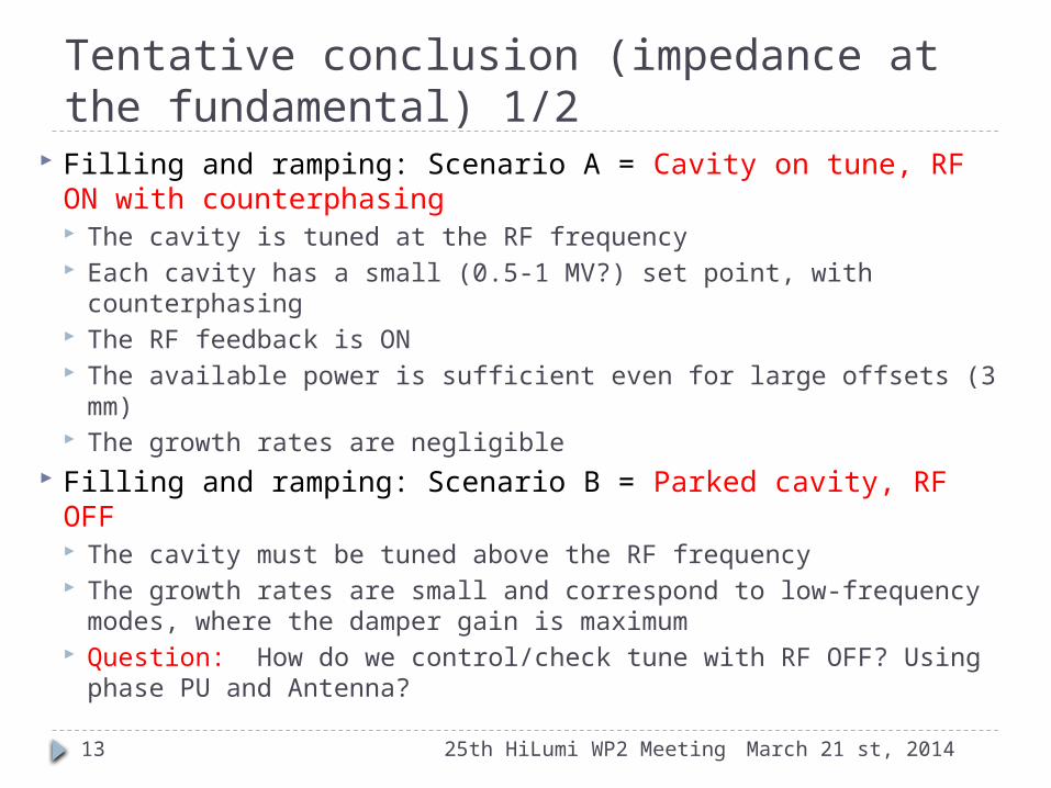
Filling and ramping: Scenario A = Cavity on tune, RF ON with counterphasing The cavity is tuned at the RF frequency Each cavity has a small (0.5-1 MV?) set point, with
counterphasing The RF feedback is ON The available power is sufficient even for large offsets (3 mm) The growth rates are negligible
Filling and ramping: Scenario B = Parked cavity, RF OFF The cavity must be tuned above the RF frequency The growth rates are small and correspond to low-frequency
modes, where the damper gain is maximum Question: How do we control/check tune with RF OFF? Using
phase PU and Antenna?
March 21 st, 201425th HiLumi WP2 Meeting13
Tentative conclusion (impedance at the fundamental) 2/2 Crabbing The cavity will be on-tune The RF feedback is needed for precision of the
kicks and reduction of TX noise It will reduce the growth rate to values compatible
with the damper. The unstable modes correspond to low frequency transverse oscillations
March 21 st, 201425th HiLumi WP2 Meeting14

RF noise
March 21 st, 201425th HiLumi WP2 Meeting15
Scaling the ACS noise to CCs
March 21 st, 201425th HiLumi WP2 Meeting
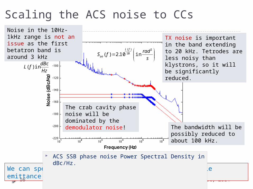
The crab cavity phase noise will be dominated by the demodulator noise!
We can specify demodulator noise levels for acceptable emittance growth
Noise in the 10Hz-1kHz range is not an issue as the first betatron band is around 3 kHz
16
TX noise is important in the band extending to 20 kHz. Tetrodes are less noisy than klystrons, so it will be significantly reduced.
ACS SSB phase noise Power Spectral Density in dBc/Hz.
The bandwidth will be possibly reduced to about 100 kHz.
s
radfS
fL 210
)(
in10.2 )(
Hz
dBcfL in)(

Phase Noise
March 21 st, 201425th HiLumi WP2 Meeting17
Phase Noise
For an emittance growth rate of approximately 5%/hour the demodulator noise level should be in the order of -147 dBc/Hz with a 100 kHz challenging, or -152 dBc/Hz (very challenging) with a 300 kHz bandwidth,
This specification could be relaxed by 6 dB or so by increasing the ADT gain at low frequencies.
This estimate is for 8 cavities per beam per plane.
22 2
2 *
16 1 tan( / 2)(( ) )
2rev
revnRF
d c fS n f
dt g
20 required improvementdB
ν 64.31
Δν 0.0015
θc (μrad) 500
Vc (MV) 3
β* (cm) 20
βcc (m) 4000
gADT 0.1
Amplitude Noise
March 21 st, 201425th HiLumi WP2 Meeting18
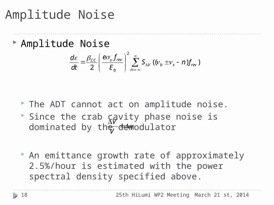
Amplitude Noise
The ADT cannot act on amplitude noise. Since the crab cavity phase noise is dominated by
the demodulator
Αn emittance growth rate of approximately 2.5%/hour is estimated with the power spectral density specified above.
2
(( ) )2
revCCV b s rev
nb
e fdS n f
dt E
V
V
Operational scenario
March 21 st, 201425th HiLumi WP2 Meeting19

Operational scenario (1) The RF is ON, with strong RF feedback and tune controls at all
time. Cavities are on-tune at all time. During filling, ramping or operation with transparent crab cavities,
we keep them on-tune with a small field requested for the active Tuning system (scenario A). As the crabbing kick is provided by three cavities we use counter-phasing to make the total field invisible to the beam. The RF feedback is used with the cavity tuned to provide stability and keep the Beam Induced Voltage zero if the beam is off-centered. We can use the demanded TX power as a measurement of beam loading to guide the beam centering.
ON flat top we drive counter-phasing to zero. Any luminosity leveling scheme is possible by synchronously changing the voltage or phase in each crab cavity as desired.
March 21 st, 201425th HiLumi WP2 Meeting20
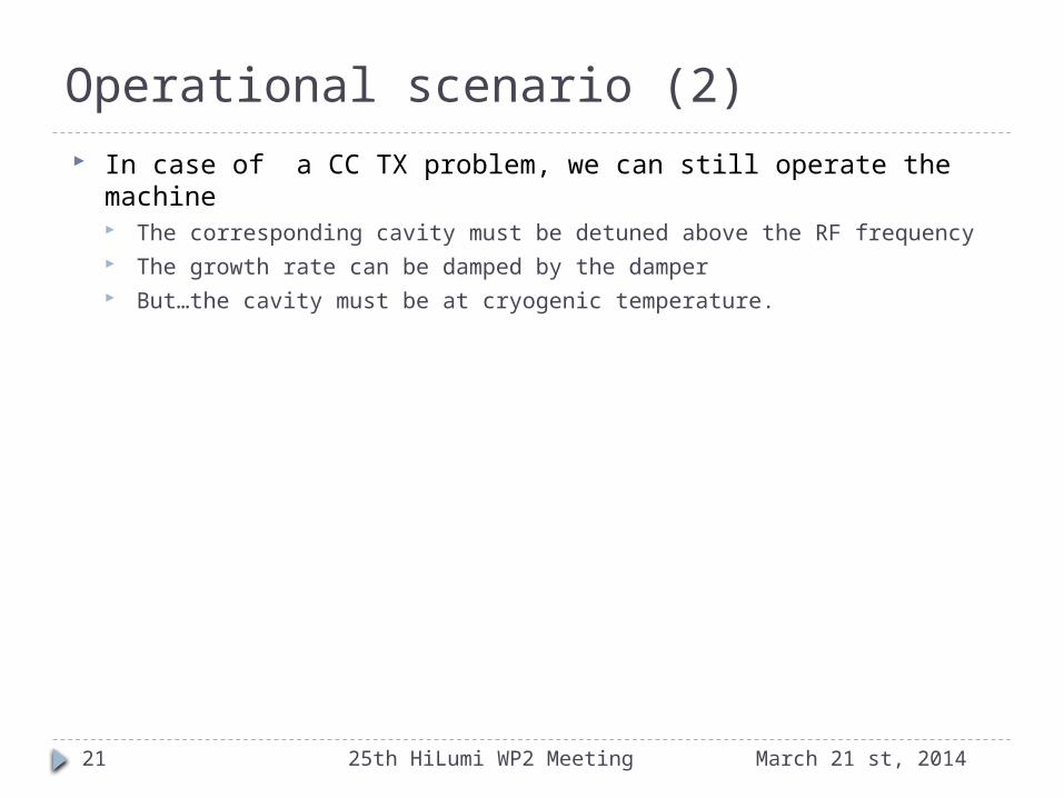
Operational scenario (2) In case of a CC TX problem, we can still operate the machine
The corresponding cavity must be detuned above the RF frequency The growth rate can be damped by the damper But…the cavity must be at cryogenic temperature.
March 21 st, 201425th HiLumi WP2 Meeting21

Conclusions
March 21 st, 201425th HiLumi WP2 Meeting22
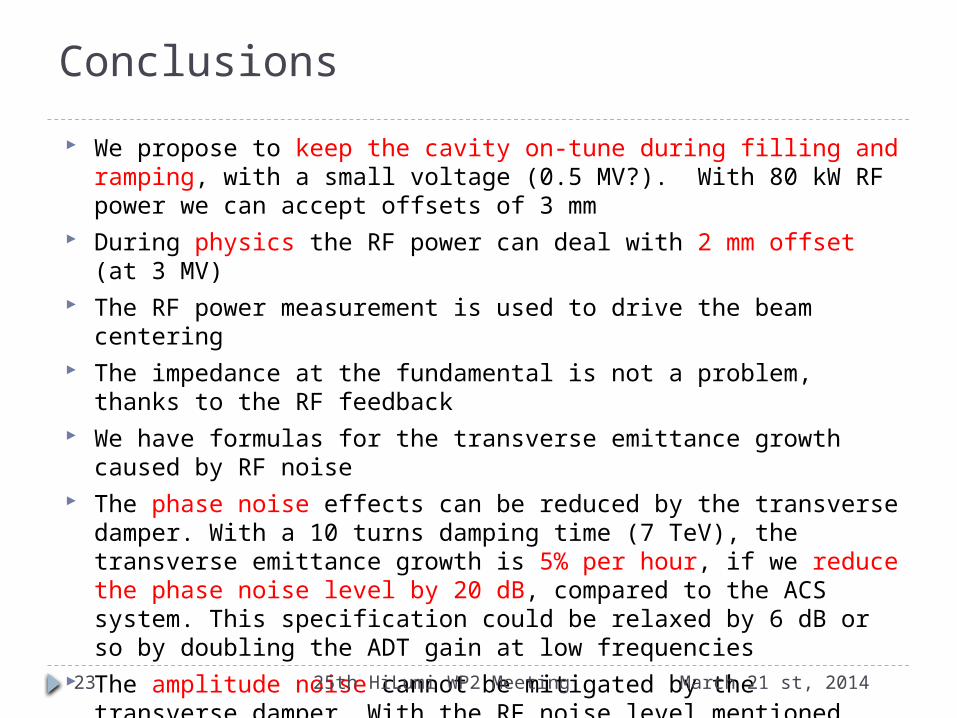
We propose to keep the cavity on-tune during filling and ramping, with a small voltage (0.5 MV?). With 80 kW RF power we can accept offsets of 3 mm
During physics the RF power can deal with 2 mm offset (at 3 MV) The RF power measurement is used to drive the beam centering The impedance at the fundamental is not a problem, thanks to the
RF feedback We have formulas for the transverse emittance growth caused by
RF noise The phase noise effects can be reduced by the transverse damper.
With a 10 turns damping time (7 TeV), the transverse emittance growth is 5% per hour, if we reduce the phase noise level by 20 dB, compared to the ACS system. This specification could be relaxed by 6 dB or so by doubling the ADT gain at low frequencies
The amplitude noise cannot be mitigated by the transverse damper. With the RF noise level mentioned above, we estimate the emittance growth around 2.5% per hour.
March 21 st, 201425th HiLumi WP2 Meeting23
Conclusions

Back-up slides
March 21 st, 201425th HiLumi WP2 Meeting24
ACS phase modulation scheme
March 21 st, 201425th HiLumi WP2 Meeting25

Present scheme RF/LLRF is currently setup for extremely
stable RF voltage (minimize transient beam loading effects). Less than 1 RF phase modulation over the turn with 0.35 A DC (7 ps)
To continue this way, we would need at least 300 kW of klystron forward power at ultimate intensity (1.7E11 ppb)
Klystrons saturate at 200 kW with present DC parameters (ultimately 300 kW).
Sufficient margin necessary for reliable operation, additional RF manipulations etc.
At 7 TeV, 1.1 A DC, the synchrotron radiation loss is 14 keV per turn, or 27 pW
All RF power is dissipated in the circulator loads
The present scheme cannot be extended much beyond nominal.
Required klystron power for 1.15e11 ppb, 25 ns, 7 TeV, 1.7e11 ppb, 25 ns, 450 GeV, 1.7e11 ppb, 25 ns, 7 TeV
26
P. Baudrenghien, T. Mastoridis, “Proposal for an RF Roadmap Towards Ultimate Intensity in the LHC", IPAC 2012
March 21 st, 201425th HiLumi WP2 Meeting
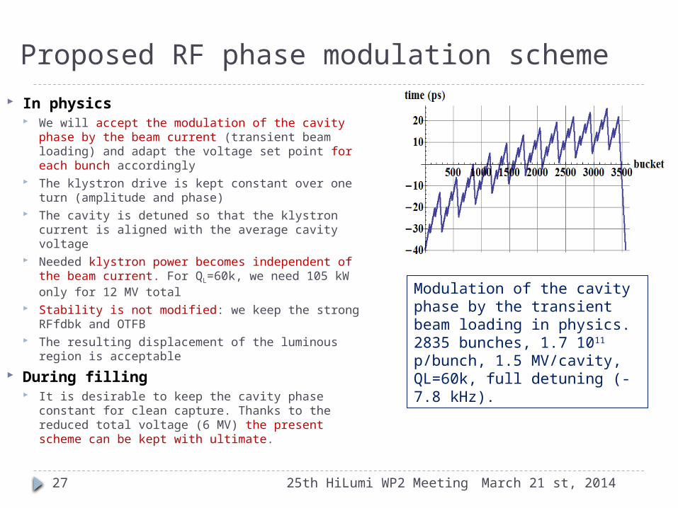
Proposed RF phase modulation scheme In physics
We will accept the modulation of the cavity phase by the beam current (transient beam loading) and adapt the voltage set point for each bunch accordingly
The klystron drive is kept constant over one turn (amplitude and phase)
The cavity is detuned so that the klystron current is aligned with the average cavity voltage
Needed klystron power becomes independent of the beam current. For QL=60k, we need 105 kW only for 12 MV total
Stability is not modified: we keep the strong RFfdbk and OTFB
The resulting displacement of the luminous region is acceptable
During filling It is desirable to keep the cavity phase constant
for clean capture. Thanks to the reduced total voltage (6 MV) the present scheme can be kept with ultimate.
Modulation of the cavity phase by the transient beam loading in physics. 2835 bunches, 1.7 1011 p/bunch, 1.5 MV/cavity, QL=60k, full detuning (-7.8 kHz).
27 March 21 st, 201425th HiLumi WP2 Meeting
Consequences for the CC (1)
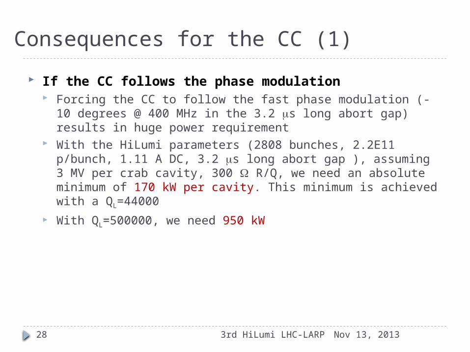
If the CC follows the phase modulation Forcing the CC to follow the fast phase modulation (-10 degrees
@ 400 MHz in the 3.2 ms long abort gap) results in huge power requirement
With the HiLumi parameters (2808 bunches, 2.2E11 p/bunch, 1.11 A DC, 3.2 ms long abort gap ), assuming 3 MV per crab cavity, 300 W R/Q, we need an absolute minimum of 170 kW per cavity. This minimum is achieved with a QL=44000
With QL=500000, we need 950 kW
28 Nov 13, 20133rd HiLumi LHC-LARP
Consequences for the CC (2)
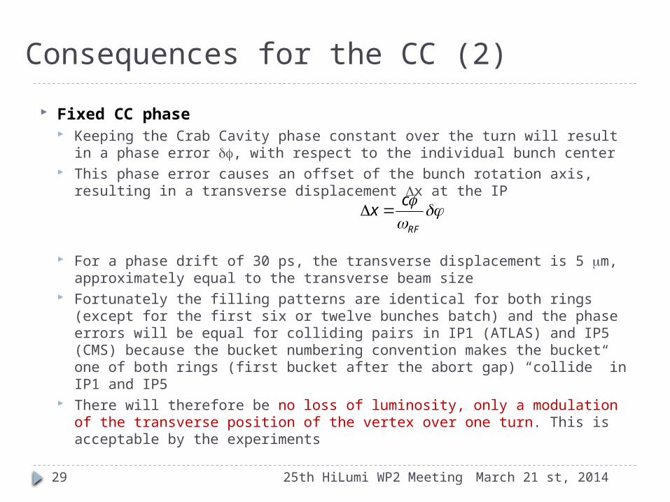
Fixed CC phase Keeping the Crab Cavity phase constant over the turn will result in a
phase error df, with respect to the individual bunch center This phase error causes an offset of the bunch rotation axis, resulting
in a transverse displacement Dx at the IP
For a phase drift of 30 ps, the transverse displacement is 5 mm, approximately equal to the transverse beam size
Fortunately the filling patterns are identical for both rings (except for the first six or twelve bunches batch) and the phase errors will be equal for colliding pairs in IP1 (ATLAS) and IP5 (CMS) because the bucket numbering convention makes the bucket one of both rings (first bucket after the abort gap) “collide” in IP1 and IP5
There will therefore be no loss of luminosity, only a modulation of the transverse position of the vertex over one turn. This is acceptable by the experiments
29
RF
cx
March 21 st, 201425th HiLumi WP2 Meeting
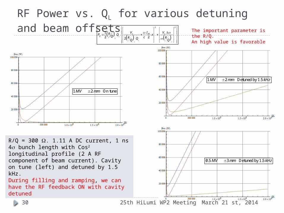
RF Power vs. QL for various detuning and beam offsets
R/Q = 300 W. 1.11 A DC current, 1 ns 4s bunch length with Cos2 longitudinal profile (2 A RF component of beam current). Cavity on tune (left) and detuned by 1.5 kHz. During filling and ramping, we can have the RF feedback ON with cavity detuned
1 2 On tuneMV mm
1 2 Detuned by 1.5MV mm kHz
2 2
1
2 22L
L
x xRFg
V VIRP Q xQ cR RQQ Q
0.5 3 Detuned by 1.5MV mm kHz
The important parameter is the R/Q. An high value is favorable
March 21 st, 201425th HiLumi WP2 Meeting30