up the environmental dangers degreasing - InfoHouseinfohouse.p2ric.org/ref/27/26368.pdf · through...
17
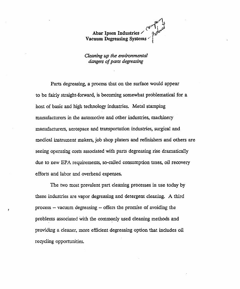
p4- Y Abar Ipsen Industries Vacuum Degreasing Systems ' * Cleming up the environmental dangers of parts degreasing Parts degreasing, a process that on the surface would appear to be fairly straight-forward, is becoming somewhat problematical for a host of basic and high technology industries. Metal stamping manufacturers in the automotive and other industries, machinery manufacturers, aerospace and transportation industries, surgical and medical instrument makers, job shop platers and refinishers and others are seeing operating costs associated with parts degreasing rise dramatically due to new EPA requirements, so-called consumption taxes, oil recovery efforts and labor and overhead expenses. The two most prevalent part cleaning processes in use today by these industries are vapor degreasing and detergent cleaning. A third process -- vacuum degreasing -- offers the promise of avoiding the problems associated with the commonly used cleaning methods and providing a cleaner, more efficientdegreasing option that includes oil recycling opportunities.
-
Upload
truonghuong -
Category
Documents
-
view
219 -
download
0
Transcript of up the environmental dangers degreasing - InfoHouseinfohouse.p2ric.org/ref/27/26368.pdf · through...
p 4 - Y Abar Ipsen Industries
Vacuum Degreasing Systems '*
Cleming up the environmental dangers of parts degreasing
Parts degreasing, a process that on the surface would appear
to be fairly straight-forward, is becoming somewhat problematical for a
host of basic and high technology industries. Metal stamping
manufacturers in the automotive and other industries, machinery
manufacturers, aerospace and transportation industries, surgical and
medical instrument makers, job shop platers and refinishers and others are
seeing operating costs associated with parts degreasing rise dramatically
due to new EPA requirements, so-called consumption taxes, oil recovery
efforts and labor and overhead expenses.
The two most prevalent part cleaning processes in use today by
these industries are vapor degreasing and detergent cleaning. A third
process -- vacuum degreasing -- offers the promise of avoiding the
problems associated with the commonly used cleaning methods and
providing a cleaner, more efficient degreasing option that includes oil
recycling opportunities.
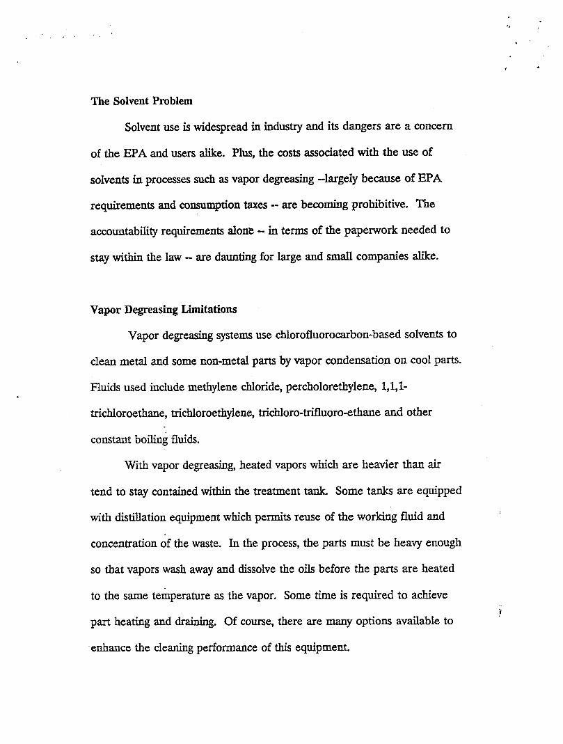
The Solvent Problem
Solvent use is widespread in industry and its dangers are a concem
of the EPA and users alike. Plus, the costs associated with the use of
solvents in processes such as vapor degreasing -largely because of EPA
requirements and consumption taxes - are becoming prohibitive. The
accountability requirements alone - in terms of the paperwork needed to
stay within the law - are daunting for large and small companies alike.
Vapor Degreasing Limitations
Vapor degreasing systems use chlorofluorocarbon-based solvents to
clean metal and some non-metal parts by vapor condensation on cool parts.
Fluids used include methylene chloride, percholorethylene, 1,1,1-
trichloroethane, trichloroethylene, trichloro-trifluoro-ethane and other
constant boil& fluids.
With vapor degreasing, heated vapors which are heavier than air
tend to stay contained within the treatment tank Some tanks are equipped
with distillation equipment which permits reuse of the working fluid and
concentration of the waste. In the process, the parts must be heavy enough
so that vapors wash away and dissolve the oils before the parts are heated
to the same temperature as the vapor. Some time is required to achieve
part heating and draining. Of course, there are many options available to i
enhance the cleaning performance of this equipment.
The Alternative in Principle
Vacuum degreasing of metal parts is already used by many
companies. The principle of vacuum boil-off of oils has been demonstrated
for many years in distillation towers. The principle is sound; however,
current techniques do not take full advantage of all the benefits inherent in
this process.
Vacuum furnaces have been used to effect the boil-off of oils for
many years. Here is the problem with forcing vacuum furnaces to do
double-duty as degreasing systems: the oil that has condensed on the water-
cooled vessel waUs can re-vaporize at high vacuum conditions. Drawn
through the furnace diEusion pumps, this oil can degrade pump
performance. To maintain the integrity of the equipment, frequent
cleaning of the hot zone, tank walls and pump components must be
performed.
A further drawback of this technique is that it does not include any
oil recycling capabilities.
Adapting Existing TechnoIogy
Recent efforts by the Abar Ipsen Industries Special Products Group to
- specially adapt existing furdace technology -- the company's area of
expertise - to help solve the problems associated with parts degreasing
have produced a new entry in the field.
The process is effective; but users are now finding that the expenses
incurred to properly dispose of oils containing chlorofluorocarbons 0- toxic
waste, really -- are eroding profits. Also, recycling oiIs with EPA-controlled
chlorofluorocarbon contaminants is expensive.
Ultrasonic Vapor Cleaning
Ultrasonic vapor degreasing is essentially the same ‘as vapor
degreasing except parts are subjected to an additional ultrasonic process to
enhance cleaning. Toxic waste disposal and all of the other problems
common to solvent usage are still concerns here.
Washer Saponification Limitations
Washer cleaning eliminates the use of chlorofluorocarbons at the
expense of speed and efficiency. The process is labor intensive and
involves extensive equipment downtime to faditate cleaning and other
maintenance requirements. Several tanks are required; the water must be
co&tantly changed; and the tanks must be cleaned repeatedly. Also,
dangerous acids and caustics must be used to emuhi.@ the oils.
Reclamation of oils in this process requires extensive and expensive
waste-water treatment to separate the oil and water. 5
. .
Abar Ipsen's vacuum degreasing system design physically separates
oils from metal parts; collects oils for recycling; and eliminates the furnace
wall oil deposit problem through the use of a unique hot-wall degreasing
method. The secret to the design is the control it provides over where the
# vacuum vapors condense; this, in turn, reduces pollution emissions to
allowable levels.
The benefits of this system over the existing processes include the
elimination of solvent handling, treatment, storage and disposal costs found
with vapor degreasing; and the elimination of caustic chemical usage, high
maintenance requirements and large floor space required of chemical
cleaning. Plus, parts requiring other types of heat treatment under vacuum
do not become water soaked with this degreasing method. Finally, oil
recycling, in most cases, is a simple process with this system.
Design Advantages vs. Existing Systems
The advantages of hot-wall degreasing over the vacuum furnace
technique lie in the reduction of the maintenance costs and the recycling
benefit.
With this equipment, oils will not condense on the vessel walls
-because the walls are hotter than the vapor. Vapors are pumped to a cold
condenser which acts like a cold-trap. A mechanical vacuum blower and
forepump continue pumping non-condensable gases.
i
Oil condenses on a series of tubes and fins in a refrigerated heat
exchanger in the system. Later in the process cycle, the condenser is
isolated from the vacuum and warmed, causing the oil to drain to a sump
for recycling or disposal. This feature eliminates the frequent cleaning and
maintenance required in systems without hot-wall shells. Also, separating
the oil before the cross-over to high vacuum prevents diffusion pump oils
from becoming prematurely degraded.
New Component Designs Required.
A new type of vessel design was required for the development of
hot-wall degreasing. The vessel wall operating temperature is 500°F; while
insulation maintains sheathing temperatures under 100°F (ambient 80°F).
A double wall design provides a vacuum interface between the inner and
outer walls of the furnace chamber, allowing the inner wall to maintain
temperatures above the condensing temperature of the oil to be removed.
This assures nearly all of the oil or grease is pumped to the refrigerated
condensing trap.
The vessel is supported and anchored to eliminate stresses and local
bending from thermal expansion and contraction. Penetrations permitting
thermocouple use are located near the door flange to reduce thermal
!
i stresses, as well.
, . .-•
The second hurdle in arriving at a fully realized system involved the
design of the refrigerated condenser. The design had to allow the
condensation of oil vapors outside of the hot-wall vessel and upstream of
the vacuum pumps. This configuration prevents oil from the degreasing
process from degrading the vacuum pump oils. The refrigerated condenser
also acts like a eryopump - increasing the effective pumping speed.
Pumpdown time is dependent on the mass of the load being heated
and the vapor pressure of the oil being removed. When equilibrium is
reached, the oil vaporizes from the work and condenses on the condenser
plates.
A typical pumping schematic is shown here. The arrangement
allows rapid pumping that bypasses the condenser at vacuum pressures
over 25 Torr. Oil vaporization does not start until pressures are below
1000 uHg. Semi-continuous processing can, according to Abar Ipsen, be
accommodated by using dual condensers.
The coils in the condensers are cooled by refrigerant. Earlier
'designs used chilled water. This, however, required a refrigerant cooling
system receiving 50°F to 60°F water. (Furnace and diffusion p&p water
seldom runs below 9OOF.) The direct refrigerant cooling system eliminates
the need for water circulators and conditioners. Also, lower temperatures 5 . could be achieved in the vacuum-system, allowing, in turn, higher capture
coefficients for the condensables,
The refrigeration system also includes a hot gas defrost loop that
allows the coils to be heated to reliquify oils and drain them from the
condenser. The condenser is isolated from the vacuum pump and vessel
during defrosting. Gas flows down across the heat exchanger fins and
encourages the flow of oil
into the sump. The mist laden gas stream then passes through a demister
to reduce combustibles content and is subsequently vented. A flare vent
stack may be required to reduce the emission of remaining combustibles to
acceptable EPA limits.
Basic Configurations
The system's vessel is designed so that it can be configured for
either horizontal or vertical operation. Vertical units can be top or bottom
loaded. A variety of sizes are available to meet various batch applications.
According to the manufacturer, the degreasing system can be used
in clean room applications by adding a vacuum jacket to the vessel. Also,
ports can be added to the vacuum chamber for RGA, optical pyrometer or
spectroscopy analysis and cleanliness verification.
To assure the safety of the operators, the system is designed to
backfill with nitrogen and/or air prior to the removal of parts. Inert gas
cooling is also available.
, . . I *
I
Environmental Concerns
An array of technology -- some of which can be bundled with the
Abar Ipsen equipment -- is available to eliminate the relatively minor
environmental hazards associated with vacuum degreasing. Vented gas
and air streams, vacuum pump exhaust and machine fumes can be treated
using filters, electrostatic precipitators, demisters and other types of
equipment to stop unsafe emissions into the plant air and outside
atmosphere. Also, cooling water and other liquids should be treated to
meet clean water standards. Solids remaining in the chamber can be
concentrated by chemical or thermal processing and disposed of safely.
Low boiling point oil components which evaporate off but are not
collected on the condenser because of high vapor pressure can be
incinerated in flare vent stacks. This converts most of the mass to carbon
dioxide and water. The remaining waste ash must be tested and disposed
of in a land €ill or by other appropriate solid containment methods.
Recycling Oils
Recycling many of oils collected during the vacuum degreasing
process requires only ultra-fine filtering. Some oils, however, may be
degraded in the process. These products may require additives or re-
blending to recapture original specifications. 5
According to Abar Ipsen, the company will test small work samples
from prospective purchasers to determine recycling potential and the
overall viability of the vacuum degreasing process for specific applications.
Of course, if the oils originally contained no hazardous constituents,
they could be burned as waste oil. Contaminated oils could not be
recycIed and might require more extensive treatment prior to disposal.
Market Potential _.
Abar Ipsen sees initial appeal for its system among current vapor
degreaser users who use large quantities of solvents. According to the
firm, the market should expand quickly as the viability of the equipment is
further demonstrated.
Oil & Parts Testing Procedures
Potential users of Abar Ipsen's vacuum degreasing system may submit
sample oil and small parts to evaluate results for their specific applications.
Full test request instructions and pricing information can be obtained by
writing Abar Ipsen
-Blvd., Feasterville,
Industries, Special Products Group, 905 Pennsylvania
Pa 19047.
1. Sample Submission
* Submission of Material Safety Data Sheets prior to
acceptance of samples for testing.
* Prepare and ship one quart or liter of sample of oil in a DOT
approved container for Hazardous Materials properly
labeled.
2. Sample Testing
* VerScation/Classication
Density Check
Viscosity Measurement
* Vapor Pressure vs. Temperature
Determine boiling point range at atmospheric pressures
per ASTM D86
Bell jar testing to determine boiling temperature at reduced
pressures
* Product Configuration Testing
Parts tested in hot-wall furnace with oil condensate chamber
to determine actual oil removal and collection rates.
* Cleanliness
Cleaning effectiveness determined using U V light reflectance
and particle size checks. i
3. Test Report
* A computer generated report will be supplied for the testing
performed.
Computer simulation calculations will show temperature and
vacuum vs. time for conditions analyzed.
* Recommended cycles will be listed for the product, furnace
and oil combination evaluated.
Parts DegreasindCleaning Study: A Summary of the Findings
Research reveh industry seeks alternative forparts degrem'ng
A recent research study commissioned by Abar Ipsen Industries,
Feasterville, Pennsylvania indicates that many people involved in industries
where parts degreasing processes are used are seeking alternatives to the
traditional cleaning methods. The conclusion of the survey is that an
environmentally safe cleaning process, such as the Abar Ipsen vacuum
degreasing system, would fulfill a perceived need in these industries and
could help solve a host of economic problems presently confronting users
of vapor degreasing and aqueous/detergent cleaning systems.
AN OVERVIEW
The research study -- in the form of a direct mail survey of a cross-section
of industries where parts degreasing is prevalent -- was conducted in April,
1990. A long and fairly complex survey questionnaire was mailed once to
sample groups in the target industries. The survey audience was not pre-
alerted, nor were there follow-ups to the responses. The response rate .-
achieved --qualified as "good" from a market research standpoint -- indicates that interest in a solution to current degreasing problem is high.
2
1
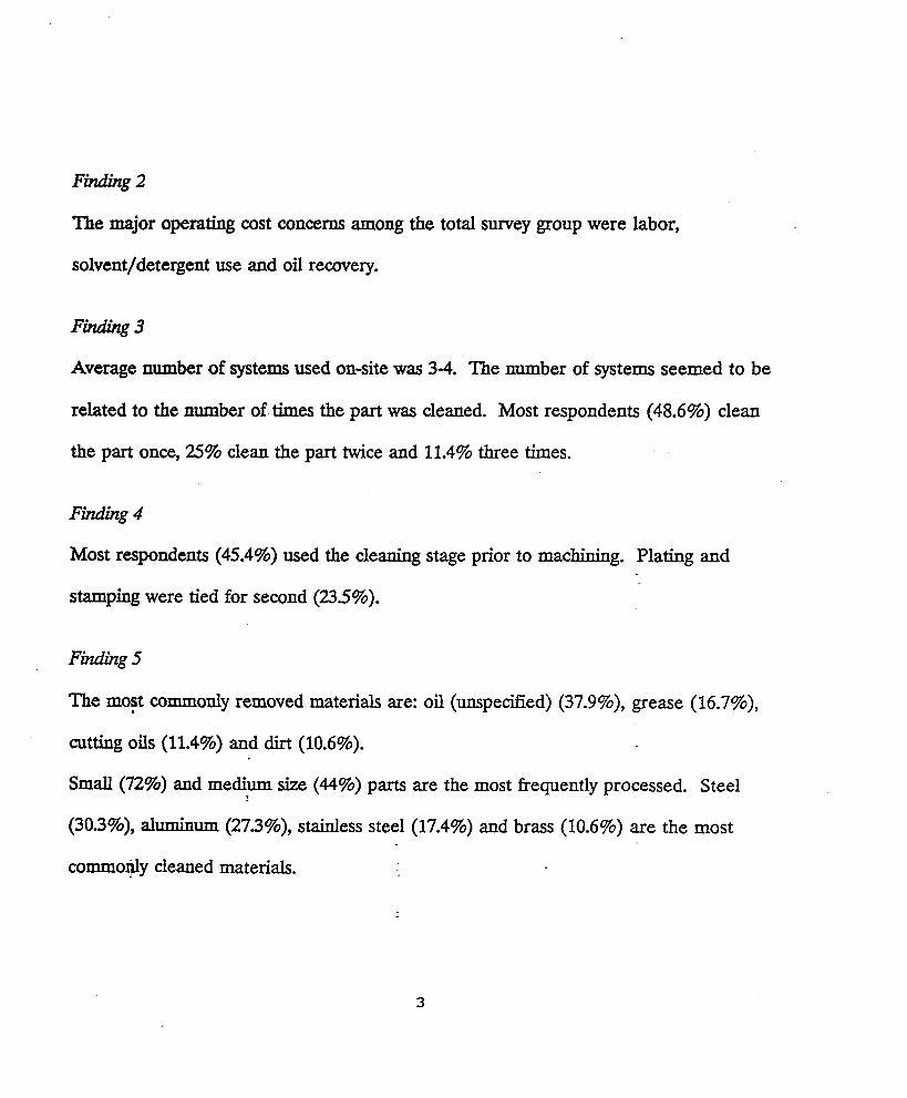
The survey field consisted of two main groups: jobshop electroplaterslcoaters and
manufacturing engineers in selected industries. These industries consisted of:
* Automotive Stampings (SIC 3465)
* Metal Stampings (SIC 3469)
* Industrial & Commercial Machinery & Computer Equipment Makers (SIC 35)
* Transportation Equipment Manufacturers (SIC 37)
* Surgical, Medical & Dental Instrument Makers (SIC 3841)
* Orthopedic, Prosthetic & Surgical Appliance Manufacturers (SIC 3842)
STUDY RESULTS
Findings based on the responses to the survey included the following (totals in some
response categories exceed 100% because of multiple responses):
Finding 1
Solvent/vapor degreasing systems are st i l l the most widely used cleaning method.
Rankir;gs for the top cleaning methods were:
1. 84.8% - vapor degreasing
2. 26.5 - aqueous detergent
3. 15.9 - ultrasonic vapor
4. 14.4 - biodegradable
5. 12.9 - ultrasonic aqueous
i
2
Finding 2
The major operating cost concerns among the total survey group were labor,
soIvent/detergent use and oil recovery.
Fhding 3
Average number of systems used on-site was 3-4. The number of systems seemed to be
related to the number of times the part was cleaned. Most respondents (48.6%) clean
the part once, 25% clean the part twice and 11.4% three times.
Finding 4
Most respondents (45.4%) used the cleaning stage prior to machining. Plating and
stamping were tied for second (23.5%).
Finding 5
The most commonly removed materials are: oil (unspecified) (37.9%), grease (16.7%),
cutting oils (11.4%) and dirt (10.6%).
Small (72%) and medium size (44%) parts axe the most frequently processed. Steel
(30.3%), a l u m i " (27.3%), stainless steel (17.4%) and brass (10.6%) are the most
commonly cleaned materials.
3
Summary
These findings suggest the Abar Ipsen vacuum degreasing system -a self-contained,
ecologically safe parts cleaning method that provides an efficient oil/grease reclamation
capability - would fulfill the process needs of users and at the same time resolve
operating cost problems that are associated with current cleaning systems.
More information on the Abar Ipsen vacuum degreasing system can be obtained by
contacting Abar Ipsen Industries, 905 Pennsylvania Blvd., Feasterville, PA 19053.
Telephone (215) 355-4900.
The Abar Ipsen Group 905 Pennsylvania Blvd. Feastemille, PA 19053
4
ABCOR" Ultrafiltration Systems
TREATING FLEXOGRAPHIC INKS AND STARCH WASH WATER BY ULTRAFILTRATION
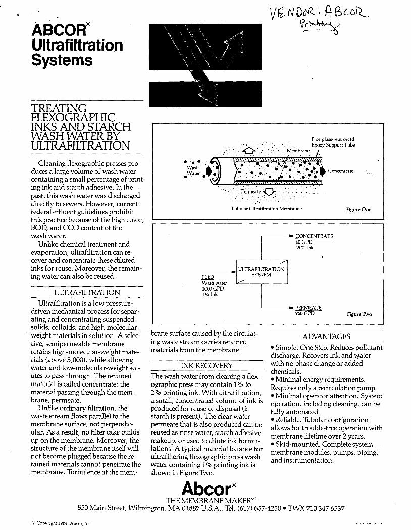
Cleaning flexographic presses pro- duces a large volume of wash water containing a small percentage of print- ing ink and starch adhesive. In the past, this wash water was discharged directly to sewers. However, current federal effluent guidelines prohibit this practice because of the high color, BOD, and COD content of the wash water.
Unlike chemical treatment and evaporation, ultrafiltration can re- cover and concentrate these diluted inks for reuse. Moreover, the remain- ing water can also be reused.
ULTRAFILTRATION Ultrafiltration is a low pressure-
driven mechanical process for separ- ating and concentrating suspended solids, colloids, and high-molecular- weight materials in solution. A selec- tive, semipermeable membrane retains high-molecular-weight mate- rials (above 5,000), while allowing water and low-molecular-weight sol- utes to pass through. The retained material is called concentrate; the material passing through the mem- brane, permeate.
Unlike ordinary filtration, the waste stream flows parallel to the membrane surface, not perpendic- ular. As a result, no filter cake builds up on the membrane. Moreover, the structure of the membrane itself will not become plugged because the re- tained materials cannot penetrate the membrane. Turbulence at the mem-
Fiberglass-reinforced
0 :.?;. Concentrate <. ~
Wash Water,
' 0 , .;;, ,
. . . . . . . . . . . . . . . . . . . . , . . . . . . . , . , .
" . . ' ( " : p e & e a t e e , .:..;.;,;: . . ; , . _ ' . .(. , ., ..;; ; , . ' . . ' . ' . . . . , , , , ; , , . '. (' ', '; '. ', . , ' . . . . . . . . .:; .. . . .
I Tubular Ultrafiltration Membrane Figure One
CONCENTRATE 40 GPD 25% Ink
ULTRAFILTRATION SYSTEM -
Wash water loo0 GPD 1% Ink I
PERMEATE 960 GPD Figure Two
brane surface caused by the circulat- ing waste stream carries retained materials from the membrane.
~
INK RECOVERY The wash water from cleaning a flex- ographic press may contain 1% to 2% printing ink. With ultrafiltration, a small, concentrated volume of ink is produced for reuse or disposal (if starch is present). The clear water permeate that is also produced can be reused as rinse water, starch adhesive makeup, or used to dilute ink formu- lations. A typical material balance for ultrafiltering flexographic press wash water containing 1% printing ink is shown in Figure Two.
Abcor"
ADVANTAGES Simple. One Step. Reduces pollutant
discharge. Recovers ink and water with no phase change or added chemicals.
Minimal energy requirements. Requires only a recirculation pump.
Minima! operator attention. System operation, including cleaning, can be fully automated.
Reliable. Tubular configuration allows for trouble-free operation with membrane lifetime over 2 years.
Skid-mounted. Complete system- membrane modules, pumps, piping, and instrumentation.
THE MEMBRANE MAKER'" 850 Main Street, Wilmington, MA 01887 U.S.A., Tel. (617) 657-4250 TWX 710 347 6537
@Copyright 1984, Abcor, Inc.


![(NOVATEC presentation SOLVENT DEGREASING SYSTEMS … · Title (NOVATEC presentation SOLVENT DEGREASING SYSTEMS [modalità compatibilità]) Author: NT10 Created Date: 3/3/2012 11:20:20](https://static.fdocuments.net/doc/165x107/6015d625f6d2f761915ef8b4/novatec-presentation-solvent-degreasing-systems-title-novatec-presentation-solvent.jpg)