UNVENTED (VENT-FREE) Gas CompaCT ClassiC … (VENT-FREE) Gas CompaCT ClassiC HEaRTH® DUal BURNER...
48
UNVENTED (VENT-FREE) GAS COMPACT CLASSIC HEARTH ® DUAL BURNER FIREPLACE OWNER’S OPERATION AND INSTALLATION MANUAL For more information, visit www.desatech.com THERMOSTAT MODELS CDCFTNA, CDCFTPA, FDCFTN, FDCFTP, VDCFTN, VDCFTP REMOTE-READY MODELS CDCFNR, CDCFPR, FDCFRN, FDCFRP, VDCFRN, VDCFRP Shown with Optional Cabinet Mantel/Hearth Base Accessory WARNING: If the information in this manual is not fol- lowed exactly, a fire or explosion may result causing property damage, personal injury, or loss of life. — Do not store or use gasoline or other flammable vapors and liquids in the vicinity of this or any other appliance. — WHAT TO DO IF YOU SMELL GAS • Do not try to light any appliance. • Do not touch any electrical switch; do not use any phone in your building. • Immediately call your gas supplier from a neighbor’s phone. Follow the gas supplier’s instructions. • If you cannot reach your gas supplier, call the fire department. — Installation and service must be performed by a quali- fied installer, service agency, or the gas supplier. INSTALLER: Leave this manual with the appliance CONSUMER: Retain this manual for future reference.
Transcript of UNVENTED (VENT-FREE) Gas CompaCT ClassiC … (VENT-FREE) Gas CompaCT ClassiC HEaRTH® DUal BURNER...
UNVENTED (VENT-FREE) Gas CompaCT ClassiC HEaRTH® DUal BURNER FiREplaCE
oWNER’s opERaTioN aND iNsTallaTioN maNUal
For more information, visit www.desatech.com
THERmosTaT moDElsCDCFTNa, CDCFTpa, FDCFTN, FDCFTp, VDCFTN, VDCFTp
REmoTE-REaDy moDElsCDCFNR, CDCFpR, FDCFRN, FDCFRp, VDCFRN, VDCFRp
Shown with Optional Cabinet Mantel/Hearth Base Accessory
WARNING: If the information in this manual is not fol-lowed exactly, a fire or explosion may result causing property damage, personal injury, or loss of life.
— Do not store or use gasoline or other flammable vapors and liquids in the vicinity of this or any other appliance.
— WHAT TO DO IF YOU SMELL GAS• Do not try to light any appliance.• Do not touch any electrical switch; do not use any
phone in your building.• Immediately call your gas supplier from a neighbor’s
phone. Follow the gas supplier’s instructions.• If you cannot reach your gas supplier, call the fire
department.— Installation and service must be performed by a quali-
fied installer, service agency, or the gas supplier.
INSTALLER: Leave this manual with the applianceCONSUMER: Retain this manual for future reference.
www.desatech.com 111244-01G2
WARNING: Improper installation, adjustment, altera-tion, service, or maintenance can cause injury or prop-erty damage. Refer to this manual for correct installation and operational procedures. For assistance or addi-tional information consult a qualified installer, service agency, or the gas supplier.
WARNING: This is an unvented gas-fired heater. It uses air (oxygen) from the room in which it is installed. Provi-sions for adequate combustion and ventilation air must be provided. Refer to Air for Combustion and Ventilation section on page 6 of this manual.
This appliance may be installed in an aftermarket,* per-manently located, manufactured (mobile) home, where not prohibited by local codes.
This appliance is only for use with the type of gas indi-cated on the rating plate. This appliance is not convert-ible for use with other gases.
* Aftermarket: Completion of sale, not for purpose of resale, from the manufacturer
TaBlE oF CoNTENTsSafety Information ............................................... 3Product Identification ........................................... 4Optional Remote Control Accessories ................. 5Local Codes......................................................... 5Product Features ................................................. 5Unpacking............................................................ 5Hood Assembly.................................................... 6Air for Combustion and Ventilation ...................... 6Installation ........................................................... 9Operating Fireplace ........................................... 22
Inspecting Burners............................................. 27Cleaning and Maintenance ................................ 28Wiring Diagram .................................................. 29Troubleshooting ................................................. 30Specifications .................................................... 34Replacement Parts ............................................ 35Service Hints ..................................................... 35Technical Service............................................... 35Illustrated Parts Breakdown and Parts List........ 36Accessories ....................................................... 44
State of Massachusetts: The installation must be made by a licensed plumber or gas fitter in the Commonwealth of Massachusetts.Sellers of unvented propane or natural gas-fired supplemental room heaters shall provide to each purchaser a copy of 527 CMR 30 upon sale of the unit.Vent-free gas products are prohibited for bedroom and bathroom installation in the Common-wealth of Massachusetts.
www.desatech.com111244-01G 3
WARNING: Do not allow fans to blow directly into the fireplace. Avoid any drafts that alter burner flame patterns. Ceiling fans can create drafts that alter burner flame patterns. Altered burner patterns can cause sooting.
Due to high temperatures, the appliance should be located out of traffic and away from furniture and draperies.
Do not place clothing or other flammable material on or near the appliance. Never place any objects on the heater.
Fireplace front and screen be-come very hot when running heater. Keep children and adults away from hot surfaces to avoid burns or clothing ignition. Fire-place will remain hot for a time after shutdown. Allow surfaces to cool before touching.
Carefully supervise young chil-dren when they are in the room with fireplace. When using the hand-held remote accessory (Remote-Ready Models Only), keep selector switch in the OFF position to prevent children from turning on burners with remote.
You must operate this fireplace with the fireplace screen in place. Make sure fireplace screen is closed before running fireplace.
Keep the appliance area clear and free from combustible ma-terials, gasoline, and other flam-mable vapors and liquids.
saFETy iNFoRmaTioN
WARNING: This product con-tains and/or generates chemicals known to the State of California to cause cancer or birth defects, or other reproductive harm.
IMPORTANT: Read this owner’s manual carefully and completely before trying to assemble, op-erate, or service this fireplace. Improper use of this fireplace can cause serious injury or death from burns, fire, explosion, electrical shock, and carbon monoxide poisoning.
DANGER: Carbon monoxide poisoning may lead to death!
Carbon Monoxide Poisoning: Early signs of carbon monoxide poisoning resemble the flu, with head-aches, dizziness, or nausea. If you have these signs, the fireplace may not be working properly. Get fresh air at once! Have fireplace serviced. Some people are more affected by carbon monoxide than others. These include pregnant women, people with heart or lung disease or anemia, those under the influence of alcohol, and those at high altitudes.Natural and Propane/LP Gas: Natural and pro-pane/LP gases are odorless. An odor-making agent is added to the gas. The odor helps you detect a gas leak. However, the odor added to the gas can fade. Gas may be present even though no odor exists.Make certain you read and understand all warnings. Keep this manual for reference. It is your guide to safe and proper operation of this fireplace.
WARNING: Any change to this fireplace or its controls can be dangerous.
WARNING: Do not use a blow-er insert, heat exchanger insert, or other accessory not approved for use with this fireplace.
www.desatech.com 111244-01G4
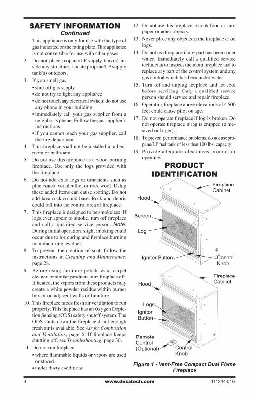
pRoDUCT iDENTiFiCaTioN
Ignitor Button
Screen
Fireplace Cabinet
Log
Control Knob
Figure 1 - Vent-Free Compact Dual Flame
Fireplace
O
FF
P
ILOT O
N
H
I
LO
Hood
Fireplace Cabinet
Logs
Ignitor Button
Remote Control (Optional) Control
Knob
Hood
saFETy iNFoRmaTioNContinued
1. This appliance is only for use with the type of gas indicated on the rating plate. This appliance is not convertible for use with other gases.
2. Do not place propane/LP supply tank(s) in-side any structure. Locate propane/LP supply tank(s) outdoors.
3. If you smell gas• shut off gas supply• do not try to light any appliance• do not touch any electrical switch; do not use
any phone in your building• immediately call your gas supplier from a
neighbor’s phone. Follow the gas supplier’s instructions
• if you cannot reach your gas supplier, call the fire department
4. This fireplace shall not be installed in a bed-room or bathroom.
5. Do not use this fireplace as a wood-burning fireplace. Use only the logs provided with the fireplace.
6. Do not add extra logs or ornaments such as pine cones, vermiculite, or rock wool. Using these added items can cause sooting. Do not add lava rock around base. Rock and debris could fall into the control area of fireplace.
7. This fireplace is designed to be smokeless. If logs ever appear to smoke, turn off fireplace and call a qualified service person. Note: During initial operation, slight smoking could occur due to log curing and fireplace burning manufacturing residues.
8. To prevent the creation of soot, follow the instructions in Cleaning and Maintenance, page 28.
9. Before using furniture polish, wax, carpet cleaner, or similar products, turn fireplace off. If heated, the vapors from these products may create a white powder residue within burner box or on adjacent walls or furniture.
10. This fireplace needs fresh air ventilation to run properly. This fireplace has an Oxygen Deple-tion Sensing (ODS) safety shutoff system. The ODS shuts down the fireplace if not enough fresh air is available. See Air for Combustion and Ventilation, page 6. If fireplace keeps shutting off, see Troubleshooting, page 30.
11. Do not run fireplace• where flammable liquids or vapors are used
or stored.• under dusty conditions.
12. Do not use this fireplace to cook food or burn paper or other objects.
13. Never place any objects in the fireplace or on logs.
14. Do not use fireplace if any part has been under water. Immediately call a qualified service technician to inspect the room fireplace and to replace any part of the control system and any gas control which has been under water.
15. Turn off and unplug fireplace and let cool before servicing. Only a qualified service person should service and repair fireplace.
16. Operating fireplace above elevations of 4,500 feet could cause pilot outage.
17. Do not operate fireplace if log is broken. Do not operate fireplace if log is chipped (dime-sized or larger).
18. To prevent performance problems, do not use pro-pane/LP fuel tank of less than 100 lbs. capacity.
19. Provide adequate clearances around air openings.
www.desatech.com111244-01G 5
opTioNal REmoTE CoNTRol aCCEssoRiEs
(For Remote-Ready Models Only)There are four optional remote controls that can be purchased separately for Remote-Ready Models only:• wall switch • hand-held ON/OFF remote• wall thermostat • hand-held thermostat remoteSee Accessories, page 44.
loCal CoDEsInstall and use fireplace with care. Follow all local codes. In the absence of local codes, use the lat-est edition of The National Fuel Gas Code ANSI Z223.1/NFPA 54*.*Available from:
American National Standards Institute, Inc.1430 Broadway
New York, NY 10018National Fire Protection Association, Inc.
Batterymarch ParkQuincy, MA 02269
pRoDUCT FEaTUREs
SAFETY PILOTThis fireplace has a pilot with an Oxygen Deple-tion Sensing (ODS) safety shutoff system. The ODS/pilot is a required feature for vent-free room fireplaces. The ODS/pilot shuts off the fireplace if there is not enough fresh air.
PIEzO IGNITION SYSTEMThis fireplace has a piezo ignitor. This system requires no matches, batteries, or other sources to light fireplace.
THERMOSTATIC HEAT CONTROL FOR THERMOSTAT-CONTROLLED MODELSThermostat-Controlled models have a thermostat sensing bulb and a control valve. The thermostat will automatically modulate the heat output to maintain a consistent room temperature. This results in greater fireplace comfort. This can also result in lower gas bills.
UNpaCkiNG
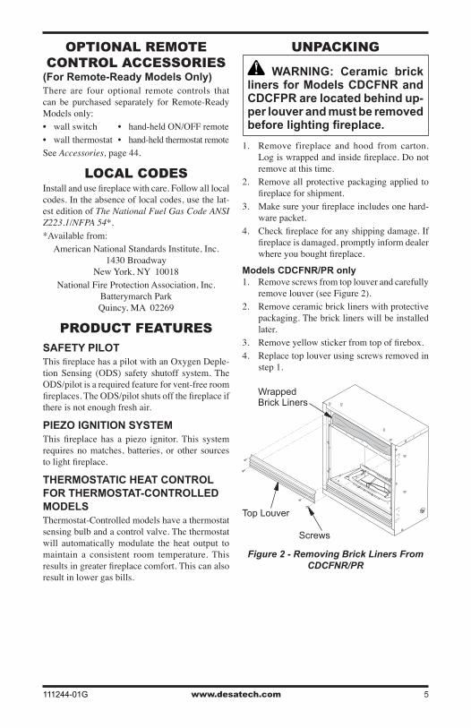
WARNING: Ceramic brick liners for Models CDCFNR and CDCFPR are located behind up-per louver and must be removed before lighting fireplace.
1. Remove fireplace and hood from carton. Log is wrapped and inside fireplace. Do not remove at this time.
2. Remove all protective packaging applied to fireplace for shipment.
3. Make sure your fireplace includes one hard-ware packet.
4. Check fireplace for any shipping damage. If fireplace is damaged, promptly inform dealer where you bought fireplace.
Models CDCFNR/PR only1. Remove screws from top louver and carefully
remove louver (see Figure 2).2. Remove ceramic brick liners with protective
packaging. The brick liners will be installed later.
3. Remove yellow sticker from top of firebox.4. Replace top louver using screws removed in
step 1.
Figure 2 - Removing Brick Liners From CDCFNR/PR
Top Louver
Screws
Wrapped Brick Liners
www.desatech.com 111244-01G6
HooD assEmBly
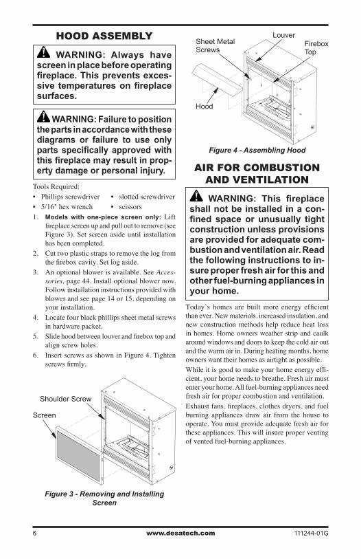
WARNING: Always have screen in place before operating fireplace. This prevents exces-sive temperatures on fireplace surfaces.
WARNING: Failure to position the parts in accordance with these diagrams or failure to use only parts specifically approved with this fireplace may result in prop-erty damage or personal injury.
Tools Required:• Phillips screwdriver • slotted screwdriver• 5/16" hex wrench • scissors 1. Models with one-piece screen only: Lift
fireplace screen up and pull out to remove (see Figure 3). Set screen aside until installation has been completed.
2. Cut two plastic straps to remove the log from the firebox cavity. Set log aside.
3. An optional blower is available. See Acces-sories, page 44. Install optional blower now. Follow installation instructions provided with blower and see page 14 or 15, depending on your installation.
4. Locate four black phillips sheet metal screws in hardware packet.
5. Slide hood between louver and firebox top and align screw holes.
6. Insert screws as shown in Figure 4. Tighten screws firmly.
Figure 3 - Removing and Installing Screen
Screen
Shoulder Screw
Figure 4 - Assembling Hood
Hood
Sheet Metal Screws
Firebox Top
Louver
aiR FoR ComBUsTioN aND VENTilaTioN
WARNING: This fireplace shall not be installed in a con-fined space or unusually tight construction unless provisions are provided for adequate com-bustion and ventilation air. Read the following instructions to in-sure proper fresh air for this and other fuel-burning appliances in your home.
Today’s homes are built more energy efficient than ever. New materials, increased insulation, and new construction methods help reduce heat loss in homes. Home owners weather strip and caulk around windows and doors to keep the cold air out and the warm air in. During heating months, home owners want their homes as airtight as possible.While it is good to make your home energy effi-cient, your home needs to breathe. Fresh air must enter your home. All fuel-burning appliances need fresh air for proper combustion and ventilation.Exhaust fans, fireplaces, clothes dryers, and fuel burning appliances draw air from the house to operate. You must provide adequate fresh air for these appliances. This will insure proper venting of vented fuel-burning appliances.
www.desatech.com111244-01G 7
PROVIDING ADEQUATE VENTILATION The following are excerpts from National Fuel Gas Code, ANSI Z223.1/NFPA 54, Section 5.3, Air for Combustion and Ventilation.All spaces in homes fall into one of the three fol-lowing ventilation classifications:1. Unusually Tight Construction2. Unconfined Space3. Confined SpaceThe information on pages 6 through 8 will help you classify your space and provide adequate ventilation.
Unusually Tight ConstructionThe air that leaks around doors and windows may provide enough fresh air for combustion and ventilation. However, in buildings of unusually tight construction, you must provide additional fresh air.Unusually tight construction is defined as construction where:a. walls and ceilings exposed to the out-
side atmosphere have a continuous water vapor retarder with a rating of one perm (6 x 10-11 kg per pa-sec-m2) or less with openings gasketed or sealed and
b. weather stripping has been added on openable windows and doors and
c. caulking or sealants are applied to areas such as joints around window and door frames, between sole plates and floors, between wall-ceiling joints, between wall panels, at penetrations for plumbing, electrical, and gas lines, and at other openings.
If your home meets all of these three criteria, you must provide additional fresh air. See Ventilation Air From Outdoors, page 8.
If your home does not meet all of the three criteria above, proceed to Determining Fresh-Air Flow For Fireplace Location.
Confined and Unconfined SpaceThe National Fuel Gas Code, ANSI Z223.1/NFPA 54 defines a confined space as a space whose volume is less than 50 cubic feet per 1,000 Btu per hour (4.8 m3 per kw) of the aggregate input
aiR FoR ComBUsTioN aND VENTilaTioN
Continued
rating of all appliances installed in that space and an unconfined space as a space whose volume is not less than 50 cubic feet per 1,000 Btu per hour (4.8 m3 per kw) of the aggregate input rating of all appliances installed in that space. Rooms com-municating directly with the space in which the appliances are installed*, through openings not furnished with doors, are considered a part of the unconfined space.* Adjoining rooms are communicating only if there are doorless passageways or ventilation grills between them.
DETERMINING FRESH-AIR FLOW FOR FIREPLACE LOCATION
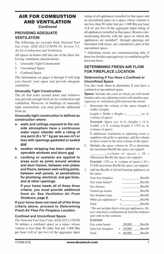
Determining if You Have a Confined or Unconfined SpaceUse this work sheet to determine if you have a confined or unconfined space.Space: Includes the room in which you will install fireplace plus any adjoining rooms with doorless pas-sageways or ventilation grills between the rooms.1. Determine the volume of the space (length x
width x height). Length x Width x Height =__________cu. ft.
(volume of space) Example: Space size 16 ft. (length) x 14 ft.
(width) x 8 ft. (ceiling height) = 1792 cu. ft. (volume of space)
If additional ventilation to adjoining room is supplied with grills or openings, add the volume of these rooms to the total volume of the space.
2. Multiply the space volume by 20 to determine the maximum Btu/Hr the space can support.
__________ (volume of space) x 20 = (Maximum Btu/Hr the space can support)
Example: 1792 cu. ft. (volume of space) x 20 = 35,840 (maximum Btu/Hr the space can support)
3. Add the Btu/Hr of all fuel burning appliances in the space.
Vent-free fireplace ____________Btu/Hr Gas water heater* ____________Btu/Hr Gas furnace ____________Btu/Hr Vented gas heater ____________Btu/Hr Gas fireplace logs ____________Btu/Hr Other gas appliances* + ____________Btu/Hr Total = ____________Btu/Hr * Do not include direct-vent gas appliances. Di-
rect-vent draws combustion air from the outdoors and vents to the outdoors.
Example: Gas water heater ____________Btu/Hr Vent-free fireplace ____________Btu/Hr Total ____________Btu/Hr
30,000+ 10,000= 40,000
www.desatech.com 111244-01G8
aiR FoR ComBUsTioN aND VENTilaTioN
Continued
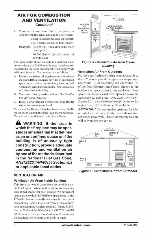
4. Compare the maximum Btu/Hr the space can support with the actual amount of Btu/Hr used.
_______ Btu/Hr (maximum the space can support) _______ Btu/Hr (actual amount of Btu/Hr used) Example: 35,840 Btu/Hr (maximum the space
can support) 40,000 Btu/Hr (actual amount of
Btu/Hr used)The space in the above example is a confined space because the actual Btu/Hr used is more than the maxi-mum Btu/Hr the space can support. You must provide additional fresh air. Your options are as follows:A. Rework worksheet, adding the space of an adjoin-
ing room. If the extra space provides an unconfined space, remove door to adjoining room or add ventilation grills between rooms. See Ventilation Air From Inside Building.
B. Vent room directly to the outdoors. See Ventila-tion Air From Outdoors.
C. Install a lower Btu/Hr fireplace, if lower Btu/Hr size makes room unconfined.
If the actual Btu/Hr used is less than the maximum Btu/Hr the space can support, the space is an unconfined space. You will need no additional fresh air ventilation.
WARNING: If the area in which the fireplace may be oper-ated is smaller than that defined as an unconfined space or if the building is of unusually tight construction, provide adequate combustion and ventilation air by one of the methods described in the National Fuel Gas Code, ANSI Z223.1/NFPA 54 Section 5.3 or applicable local codes.
VENTILATION AIR
Ventilation Air From Inside Building This fresh air would come from an adjoining un-confined space. When ventilating to an adjoining unconfined space, you must provide two permanent openings: one within 12" of the ceiling and one within 12" of the floor on the wall connecting the two spaces (see options 1 and 2, Figure 5). You can also remove door into adjoining room (see option 3, Figure 5). Fol-low the National Fuel Gas Code, ANSI Z223.1/NFPA 54, Section 5.3, Air for Combustion and Ventilation for required size of ventilation grills or ducts.
Ventilation Air From OutdoorsProvide extra fresh air by using ventilation grills or ducts. You must provide two permanent openings: one within 12" of the ceiling and one within 12" of the floor. Connect these items directly to the outdoors or spaces open to the outdoors. These spaces include attics and crawl spaces. Follow the National Fuel Gas Code, ANSI Z223.1/NFPA 54, Section 5.3, Air for Combustion and Ventilation for required size of ventilation grills or ducts. IMPORTANT: Do not provide openings for inlet or outlet air into attic if attic has a thermostat-controlled power vent. Heated air entering the attic will activate the power vent.
OutletAir
VentilatedAttic
OutletAir
InletAir
Inlet Air Ventilated Crawl Space
To CrawlSpace
To Attic
Figure 5 - Ventilation Air from Inside Building
OrRemoveDoor intoAdjoining
Room,Option
3
Ventilation Grills Into Adjoining Room,
Option 2
VentilationGrills
Into Adjoining Room,
Option 1
12"
12"
Figure 6 - Ventilation Air from Outdoors
www.desatech.com111244-01G 9
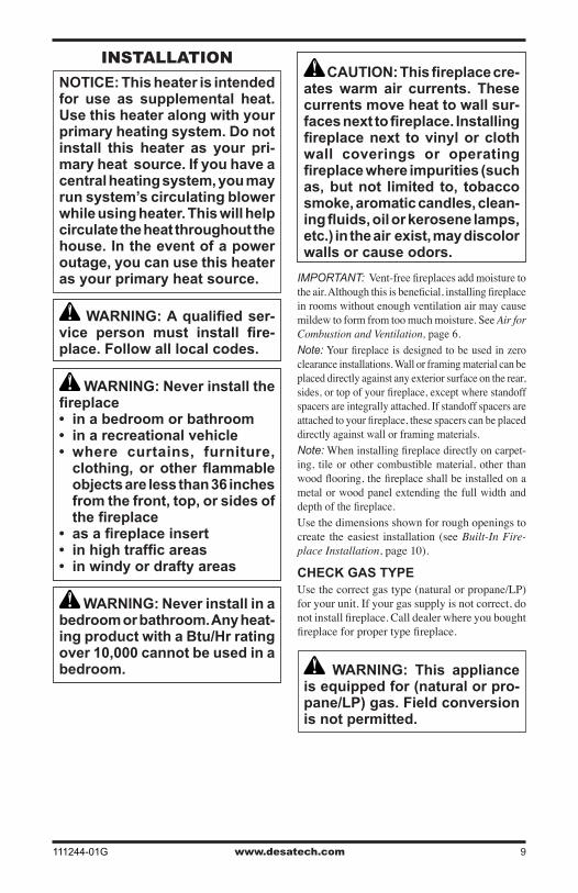
CAUTION: This fireplace cre-ates warm air currents. These currents move heat to wall sur-faces next to fireplace. Installing fireplace next to vinyl or cloth wall coverings or operating fireplace where impurities (such as, but not limited to, tobacco smoke, aromatic candles, clean-ing fluids, oil or kerosene lamps, etc.) in the air exist, may discolor walls or cause odors.
IMPORTANT: Vent-free fireplaces add moisture to the air. Although this is beneficial, installing fireplace in rooms without enough ventilation air may cause mildew to form from too much moisture. See Air for Combustion and Ventilation, page 6.Note: Your fireplace is designed to be used in zero clearance installations. Wall or framing material can be placed directly against any exterior surface on the rear, sides, or top of your fireplace, except where standoff spacers are integrally attached. If standoff spacers are attached to your fireplace, these spacers can be placed directly against wall or framing materials.Note: When installing fireplace directly on carpet-ing, tile or other combustible material, other than wood flooring, the fireplace shall be installed on a metal or wood panel extending the full width and depth of the fireplace.Use the dimensions shown for rough openings to create the easiest installation (see Built-In Fire-place Installation, page 10).
CHECK GAS TYPEUse the correct gas type (natural or propane/LP) for your unit. If your gas supply is not correct, do not install fireplace. Call dealer where you bought fireplace for proper type fireplace.
WARNING: This appliance is equipped for (natural or pro-pane/LP) gas. Field conversion is not permitted.
iNsTallaTioN
NOTICE: This heater is intended for use as supplemental heat. Use this heater along with your primary heating system. Do not install this heater as your pri-mary heat source. If you have a central heating system, you may run system’s circulating blower while using heater. This will help circulate the heat throughout the house. In the event of a power outage, you can use this heater as your primary heat source.
WARNING: A qualified ser-vice person must install fire-place. Follow all local codes.
WARNING: Never install the fireplace• in a bedroom or bathroom• in a recreational vehicle• where curtains, furniture,
clothing, or other flammable objects are less than 36 inches from the front, top, or sides of the fireplace
• as a fireplace insert• in high traffic areas• in windy or drafty areas
WARNING: Never install in a bedroom or bathroom. Any heat-ing product with a Btu/Hr rating over 10,000 cannot be used in a bedroom.
www.desatech.com 111244-01G10
INSTALLATION ITEMSBefore installing fireplace, make sure you have the items listed below.• external regulator (supplied by installer, for
propane/LP units only)• piping (check local codes)• sealant (resistant to propane/LP gas)• equipment shutoff valve *• test gauge connection*• ground joint union• sediment trap• tee joint• pipe wrench* A CSA design-certified equipment shutoff valve with 1/8" NPT tap is an acceptable alternative to test gauge connection. Purchase the optional CSA design-certified equipment shutoff valve from your dealer. See Accessories, page 44.Note: If desired, purchase a four-sided brass trim kit for built-in installations. See Accessories, page 44.
FIREPLACE CLEARANCES
WARNING: Maintain the minimum clearances shown in Figure 7. If you can, provide greater clearances from floor, ceiling, and joining wall.
If your fireplace is to be used with an optional mantel, the installation instructions included with your mantel shows an CSA approved method of attaching the fireplace/mantel system to a wall. IMPORTANT: Only use optional cabinet or corner mantels specified in this manual. Purchase the optional mantel from your dealer (see Acces-sories, page 44).If your fireplace is to be recessed into the wall, see Built-In Fireplace Installation to secure your fireplace into the wall.
CAUTION: If you install the fireplace in a home garage• fireplace pilot and burner must
be at least 18 inches above floor.
• locate fireplace where moving vehicle will not hit it.
For convenience and efficiency, install fireplace• where there is easy access for operation, inspec-
tion, and service• in coldest part of roomAn optional blower kit is available from your dealer. See Accessories, page 44. If planning to use blower, follow instructions provided with blower for power source.
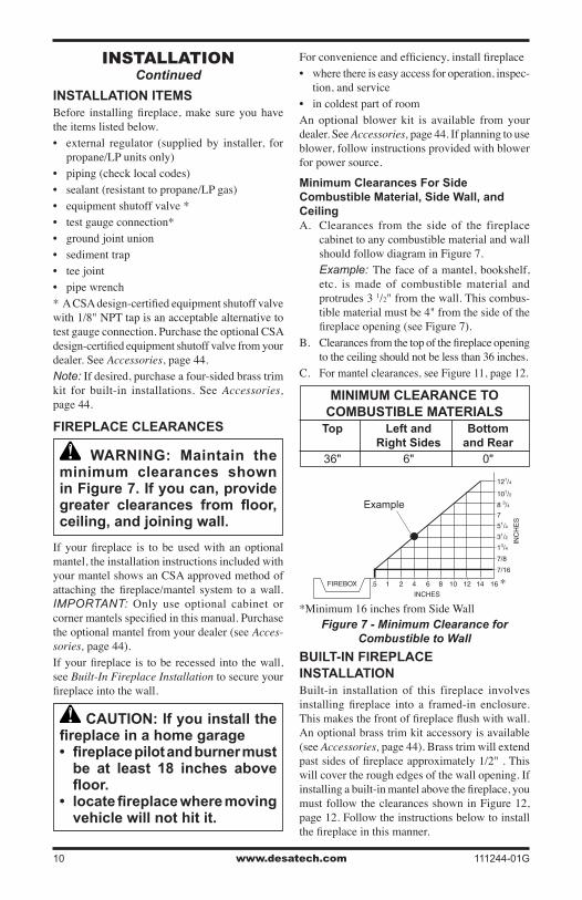
Minimum Clearances For Side Combustible Material, Side Wall, and Ceiling A. Clearances from the side of the fireplace
cabinet to any combustible material and wall should follow diagram in Figure 7.
Example: The face of a mantel, bookshelf, etc. is made of combustible material and protrudes 3 1/2" from the wall. This combus-tible material must be 4" from the side of the fireplace opening (see Figure 7).
B. Clearances from the top of the fireplace opening to the ceiling should not be less than 36 inches.
C. For mantel clearances, see Figure 11, page 12.
MINIMUM CLEARANCE TO COMBUSTIBLE MATERIALS
Top Left and Bottom Right Sides and Rear 36" 6" 0"
Figure 7 - Minimum Clearance for Combustible to Wall
*Minimum 16 inches from Side Wall
*
Example
iNsTallaTioNContinued
BUILT-IN FIREPLACE INSTALLATIONBuilt-in installation of this fireplace involves installing fireplace into a framed-in enclosure. This makes the front of fireplace flush with wall. An optional brass trim kit accessory is available (see Accessories, page 44). Brass trim will extend past sides of fireplace approximately 1/2" . This will cover the rough edges of the wall opening. If installing a built-in mantel above the fireplace, you must follow the clearances shown in Figure 12, page 12. Follow the instructions below to install the fireplace in this manner.
www.desatech.com111244-01G 11
iNsTallaTioNContinued
Figure 9 - Rough Opening for Installing in Corner
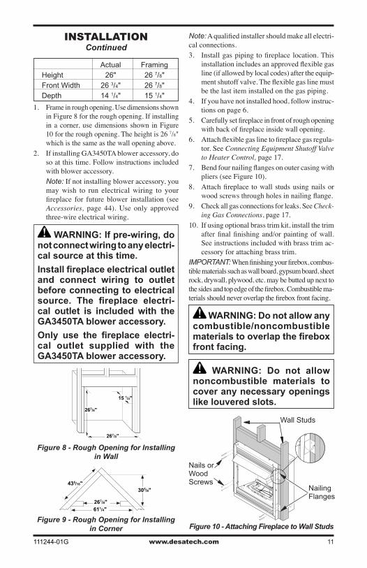
Figure 8 - Rough Opening for Installing in Wall
435/16"305/8"
611/4" 267/8"
267/8"
267/8"
3/4" OffThe FloorMinimum
15 1/4"
Actual Framing Height 26" 26 7/8" Front Width 26 3/4" 26 7/8" Depth 14 1/4" 15 1/4"
1. Frame in rough opening. Use dimensions shown in Figure 8 for the rough opening. If installing in a corner, use dimensions shown in Figure 10 for the rough opening. The height is 26 7/8" which is the same as the wall opening above.
2. If installing GA3450TA blower accessory, do so at this time. Follow instructions included with blower accessory.
Note: If not installing blower accessory, you may wish to run electrical wiring to your fireplace for future blower installation (see Accessories, page 44). Use only approved three-wire electrical wiring.
WARNING: If pre-wiring, do not connect wiring to any electri-cal source at this time.
Install fireplace electrical outlet and connect wiring to outlet before connecting to electrical source. The fireplace electri-cal outlet is included with the GA3450TA blower accessory.
Only use the fireplace electri-cal outlet supplied with the GA3450TA blower accessory.
Figure 10 - Attaching Fireplace to Wall Studs
Nailing Flanges
Nails or Wood Screws
Wall Studs
Note: A qualified installer should make all electri-cal connections.3. Install gas piping to fireplace location. This
installation includes an approved flexible gas line (if allowed by local codes) after the equip-ment shutoff valve. The flexible gas line must be the last item installed on the gas piping.
4. If you have not installed hood, follow instruc-tions on page 6.
5. Carefully set fireplace in front of rough opening with back of fireplace inside wall opening.
6. Attach flexible gas line to fireplace gas regula-tor. See Connecting Equipment Shutoff Valve to Heater Control, page 17.
7. Bend four nailing flanges on outer casing with pliers (see Figure 10).
8. Attach fireplace to wall studs using nails or wood screws through holes in nailing flange.
9. Check all gas connections for leaks. See Check-ing Gas Connections, page 17.
10. If using optional brass trim kit, install the trim after final finishing and/or painting of wall. See instructions included with brass trim ac-cessory for attaching brass trim.
IMPORTANT: When finishing your firebox, combus-tible materials such as wall board, gypsum board, sheet rock, drywall, plywood, etc. may be butted up next to the sides and top edge of the firebox. Combustible ma-terials should never overlap the firebox front facing.
WARNING: Do not allow any combustible/noncombustible materials to overlap the firebox front facing.
WARNING: Do not allow noncombustible materials to cover any necessary openings like louvered slots.
www.desatech.com 111244-01G12
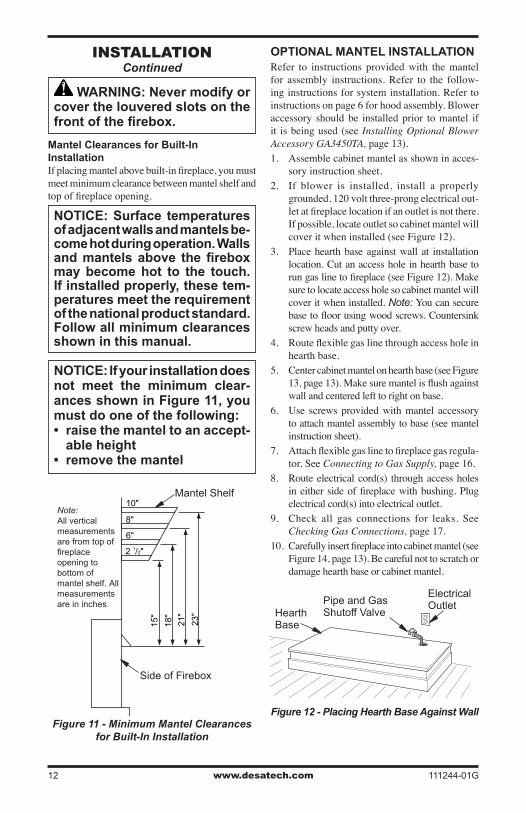
15"
18"
21"
23"
2 1/2"
6"
8"
10"Note:All verticalmeasurementsare from top offireplaceopening to bottom ofmantel shelf. Allmeasurementsare in inches.
iNsTallaTioNContinued
WARNING: Never modify or cover the louvered slots on the front of the firebox.
Mantel Clearances for Built-In InstallationIf placing mantel above built-in fireplace, you must meet minimum clearance between mantel shelf and top of fireplace opening.
NOTICE: Surface temperatures of adjacent walls and mantels be-come hot during operation. Walls and mantels above the firebox may become hot to the touch. If installed properly, these tem-peratures meet the requirement of the national product standard. Follow all minimum clearances shown in this manual.
NOTICE: If your installation does not meet the minimum clear-ances shown in Figure 11, you must do one of the following:• raise the mantel to an accept-
able height• remove the mantel
Figure 11 - Minimum Mantel Clearances for Built-In Installation
Mantel Shelf
Side of Firebox
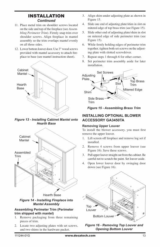
OPTIONAL MANTEL INSTALLATIONRefer to instructions provided with the mantel for assembly instructions. Refer to the follow-ing instructions for system installation. Refer to instructions on page 6 for hood assembly. Blower accessory should be installed prior to mantel if it is being used (see Installing Optional Blower Accessory GA3450TA, page 13).1. Assemble cabinet mantel as shown in acces-
sory instruction sheet.2. If blower is installed, install a properly
grounded, 120 volt three-prong electrical out-let at fireplace location if an outlet is not there. If possible, locate outlet so cabinet mantel will cover it when installed (see Figure 12).
3. Place hearth base against wall at installation location. Cut an access hole in hearth base to run gas line to fireplace (see Figure 12). Make sure to locate access hole so cabinet mantel will cover it when installed. Note: You can secure base to floor using wood screws. Countersink screw heads and putty over.
4. Route flexible gas line through access hole in hearth base.
5. Center cabinet mantel on hearth base (see Figure 13, page 13). Make sure mantel is flush against wall and centered left to right on base.
6. Use screws provided with mantel accessory to attach mantel assembly to base (see mantel instruction sheet).
7. Attach flexible gas line to fireplace gas regula-tor. See Connecting to Gas Supply, page 16.
8. Route electrical cord(s) through access holes in either side of fireplace with bushing. Plug electrical cord(s) into electrical outlet.
9. Check all gas connections for leaks. See Checking Gas Connections, page 17.
10. Carefully insert fireplace into cabinet mantel (see Figure 14, page 13). Be careful not to scratch or damage hearth base or cabinet mantel.
Figure 12 - Placing Hearth Base Against Wall
Hearth Base
Electrical OutletPipe and Gas
Shutoff Valve
www.desatech.com111244-01G 13
iNsTallaTioNContinued
Figure 16 - Removing Top Louver and Opening Bottom Louver
O
FF
P
ILOT O
N
H
I
LO
Top Louver
Bottom Louver
11. Place metal trim on shoulder screws located on the side and top of the fireplace (see Assem-bling Perimeter Trim). Firmly snap trim over shoulder screws. Align fireplace in mantel assembly so the trim overlaps mantel evenly on all three sides.
12. Lower bottom louver door. Use 3" wood screws provided with mantel accessory to attach fire-place to base (see mantel instruction sheet).
O
FF
P
ILOT O
N
H
I
LO
Assembling Perimeter Trim (Perimeter trim shipped with mantel) 1. Remove packaging from three remaining
pieces of trim. 2. Locate two adjusting plates with set screws,
and two shims in the hardware packet.
Figure 15 - Assembling Brass Trim
Side Brass Trim
Top Brass Trim
Mitered EdgeShim
Set ScrewsAdjusting Plate
Slot
3. Align shim under adjusting plate as shown in Figure 15.
4. Slide one end of adjusting plate/shim in slot on mitered edge of top brass trim (see Figure 15).
5. Slide other end of adjusting plate/shim in slot on mitered edge of side perimeter trim (see Figure 15).
6. While firmly holding edges of perimeter trim together, tighten both set screws on the adjust-ing plate with slotted screwdriver.
7. Repeat steps 1 through 6 for other corner.8. Set perimeter trim assembly aside for later
installation.
Figure 13 - Installing Cabinet Mantel onto Hearth Base
Figure 14 - Installing Fireplace into Mantel Assembly
Cabinet Mantel
Hearth Base
Cabinet Mantel
Assembled Trim
Hearth Base
INSTALLING OPTIONAL BLOWER ACCESSORY GA3450TA
Removing Upper LouverTo install the blower accessory, you must first remove the upper louver. 1. Lift screen off fireplace and remove log set if
installed.2. Remove 4 screws from upper louver (see
Figure 16). Save these screws. 3. Pull upper louver straight out from the cabinet. Be
careful not to scratch the paint. Set louver aside.4. Open lower louver door by swinging door
down (see Figure 16).
www.desatech.com 111244-01G14
iNsTallaTioNContinued
Installing Blower Accessory
CAUTION: Label all wires prior to disconnection when servicing controls. Wiring errors can cause improper and danger-ous operation.
CAUTION: Verify proper op-eration after servicing.
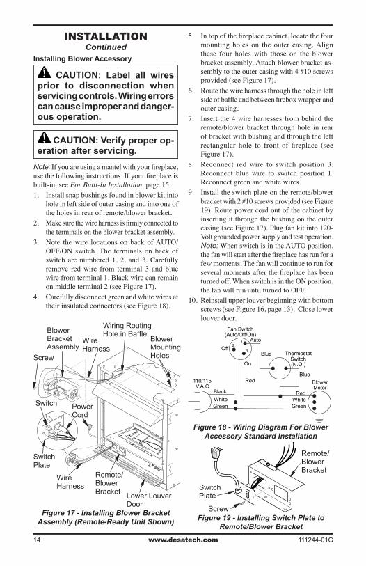
Note: If you are using a mantel with your fireplace, use the following instructions. If your fireplace is built-in, see For Built-In Installation, page 15.1. Install snap bushings found in blower kit into
hole in left side of outer casing and into one of the holes in rear of remote/blower bracket.
2. Make sure the wire harness is firmly connected to the terminals on the blower bracket assembly.
3. Note the wire locations on back of AUTO/OFF/ON switch. The terminals on back of switch are numbered 1, 2, and 3. Carefully remove red wire from terminal 3 and blue wire from terminal 1. Black wire can remain on middle terminal 2 (see Figure 17).
4. Carefully disconnect green and white wires at their insulated connectors (see Figure 18).
321
O
FF
P
ILOT O
N
H
I
L
O
Figure 17 - Installing Blower Bracket Assembly (Remote-Ready Unit Shown)
Wire Harness
Blower Bracket Assembly
Screw
Wire Harness
Switch
Wiring Routing Hole in Baffle
Switch Plate
Remote/Blower Bracket
Power Cord
Lower Louver Door
Blower Mounting Holes
Figure 19 - Installing Switch Plate to Remote/Blower Bracket
Figure 18 - Wiring Diagram For Blower Accessory Standard Installation
Red
Red
Fan Switch(Auto/Off/On)
Blue
Blue
ThermostatSwitch(N.O.)
GreenWhite
GreenWhite
On
110/115 V.A.C.
BlowerMotor
Black
Off
12
3
Auto
Remote/Blower Bracket
Switch Plate
Screw
5. In top of the fireplace cabinet, locate the four mounting holes on the outer casing. Align these four holes with those on the blower bracket assembly. Attach blower bracket as-sembly to the outer casing with 4 #10 screws provided (see Figure 17).
6. Route the wire harness through the hole in left side of baffle and between firebox wrapper and outer casing.
7. Insert the 4 wire harnesses from behind the remote/blower bracket through hole in rear of bracket with bushing and through the left rectangular hole to front of fireplace (see Figure 17).
8. Reconnect red wire to switch position 3. Reconnect blue wire to switch position 1. Reconnect green and white wires.
9. Install the switch plate on the remote/blower bracket with 2 #10 screws provided (see Figure 19). Route power cord out of the cabinet by inserting it through the bushing on the outer casing (see Figure 17). Plug fan kit into 120-Volt grounded power supply and test operation. Note: When switch is in the AUTO position, the fan will start after the fireplace has run for a few moments. The fan will continue to run for several moments after the fireplace has been turned off. When switch is in the ON position, the fan will run until turned to OFF.
10. Reinstall upper louver beginning with bottom screws (see Figure 16, page 13). Close lower louver door.
www.desatech.com111244-01G 15
iNsTallaTioNContinued
For Built-In Installation
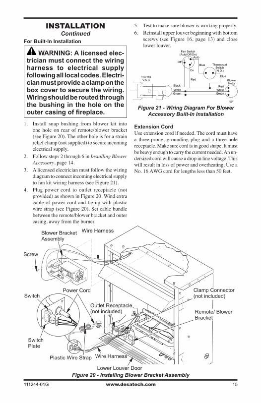
WARNING: A licensed elec-trician must connect the wiring harness to electrical supply following all local codes. Electri-cian must provide a clamp on the box cover to secure the wiring. Wiring should be routed through the bushing in the hole on the outer casing of fireplace.
1. Install snap bushing from blower kit into one hole on rear of remote/blower bracket (see Figure 20). The other hole is for a strain relief clamp (not supplied) to secure incoming electrical supply.
2. Follow steps 2 through 6 in Installing Blower Accessory, page 14.
3. A licensed electrician must follow the wiring diagram to connect incoming electrical supply to fan kit wiring harness (see Figure 21).
4. Plug power cord to outlet receptacle (not provided) as shown in Figure 20. Wind extra cable of power cord and tie up with plastic wire strap (see Figure 20). Set cable bundle between the remote/blower bracket and outer casing, away from the burner.
5. Test to make sure blower is working properly. 6. Reinstall upper louver beginning with bottom
screws (see Figure 16, page 13) and close lower louver.
321
O
FF
P
ILOT O
N
H
I
L
O
Blower Bracket Assembly
Screw
Wire Harness
Switch Plate
SwitchPower Cord
Outlet Receptacle (not included) Remote/ Blower
Bracket
Clamp Connector (not included)
Figure 20 - Installing Blower Bracket Assembly
Plastic Wire Strap Wire Harness
Lower Louver Door
Red
Red
Fan Switch(Auto/Off/On)
Blue
Blue
ThermostatSwitch(N.O.)
GreenWhite
GreenWhite
On
110/115 V.A.C. Blower
MotorBlack
Off
12
3
Auto
Extension CordUse extension cord if needed. The cord must have a three-prong, grounding plug and a three-hole receptacle. Make sure cord is in good shape. It must be heavy enough to carry the current needed. An un-dersized cord will cause a drop in line voltage. This will result in loss of power and overheating. Use a No. 16 AWG cord for lengths less than 50 feet.
Figure 21 - Wiring Diagram For Blower Accessory Built-In Installation
www.desatech.com 111244-01G16
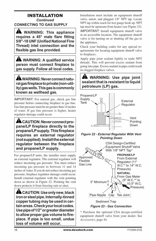
Installation must include an equipment shutoff valve, union, and plugged 1/8" NPT tap. Locate NPT tap within reach for test gauge hook up. NPT tap must be upstream from heater (see Figure 23).IMPORTANT: Install equipment shutoff valve in an accessible location. The equipment shutoff valve is for turning on or shutting off the gas to the appliance.Check your building codes for any special re-quirements for locating equipment shutoff valve to fireplaces.Apply pipe joint sealant lightly to male NPT threads. This will prevent excess sealant from going into pipe. Excess sealant in pipe could result in clogged fireplace valves.
WARNING: Use pipe joint sealant that is resistant to liquid petroleum (LP) gas.
iNsTallaTioNContinued
* Purchase the optional CSA design-certified equipment shutoff valve from your dealer. See Accessories, page 44.
Figure 23 - Gas Connection
CSA Design-Certified Equipment Shutoff Valve With 1/8" NPT Tap*
3" Minimum
Approved Flexible Gas Line
Pipe Nipple Cap Tee Joint
PROPANE/LPFrom External Regulator (11" W.C.** to 14" W.C. Pressure)NATURALFrom Gas Meter (5" W.C.** to 10.5" W.C. Pressure)
Sediment Trap
Propane/LP Supply Tank External
Regulator
Figure 22 - External Regulator With Vent Pointing Down
Vent Pointing Down
CONNECTING TO GAS SUPPLY
WARNING: This appliance requires a 45° male flare fitting 5/8"-18 UNF (Unified National Fine Thread) inlet connection and the flexible gas line provided.
WARNING: A qualified service person must connect fireplace to gas supply. Follow all local codes.
WARNING: Never connect natu-ral gas fireplace to private (non-util-ity) gas wells. This gas is commonly known as wellhead gas.
IMPORTANT: For natural gas, check gas line pressure before connecting fireplace to gas line. Gas line pressure must be no greater than 14 inches of water. If gas line pressure is higher, heater regulator damage could occur.
CAUTION: Never connect pro-pane/LP fireplace directly to the propane/LP supply. This fireplace requires an external regulator (not supplied). Install the external regulator between the fireplace and propane/LP supply.
For propane/LP units, the installer must supply an external regulator. The external regulator will reduce incoming gas pressure. You must reduce incoming gas pressure to between 11 and 14 inches of water. If you do not reduce incoming gas pressure, fireplace regulator damage could occur. Install external regulator with the vent pointing down as shown in Figure 22. Pointing the vent down protects it from freezing rain or sleet.
CAUTION: Use only new, black iron or steel pipe. Internally-tinned copper tubing may be used in cer-tain areas. Check your local codes. Use pipe of 1/2" or greater diameter to allow proper gas volume to fire-place. If pipe is too small, undue loss of volume will occur.
www.desatech.com111244-01G 17
iNsTallaTioNContinued
We recommend that you install a sediment trap in supply line as shown in Figure 23, page 16. Locate sediment trap where it is within reach for cleaning. Install in piping system between fuel supply and heater. Locate sediment trap where trapped mat-ter is not likely to freeze. A sediment trap traps moisture and contaminants. This keeps them from going into fireplace controls. If sediment trap is not installed or is installed wrong, fireplace may not run properly.
CONNECTING EQUIPMENT SHUTOFF VALVE TO HEATER CONTROL
Installation Items Needed• Phillips screwdriver • sealant (resistant to propane/LP gas, not
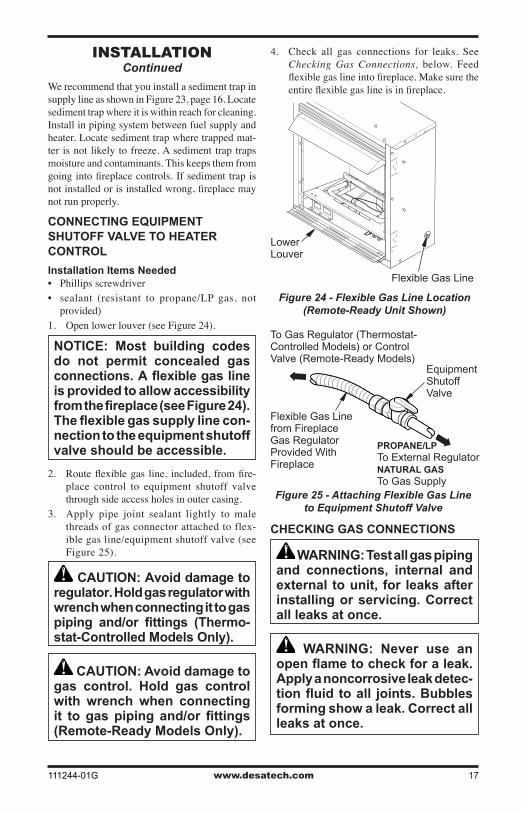
provided)1. Open lower louver (see Figure 24).
NOTICE: Most building codes do not permit concealed gas connections. A flexible gas line is provided to allow accessibility from the fireplace (see Figure 24). The flexible gas supply line con-nection to the equipment shutoff valve should be accessible.
2. Route flexible gas line, included, from fire-place control to equipment shutoff valve through side access holes in outer casing.
3. Apply pipe joint sealant lightly to male threads of gas connector attached to flex-ible gas line/equipment shutoff valve (see Figure 25).
CAUTION: Avoid damage to regulator. Hold gas regulator with wrench when connecting it to gas piping and/or fittings (Thermo-stat-Controlled Models Only).
CAUTION: Avoid damage to gas control. Hold gas control with wrench when connecting it to gas piping and/or fittings (Remote-Ready Models Only).
Figure 24 - Flexible Gas Line Location (Remote-Ready Unit Shown)
O
FF
P
ILOT O
N
H
I
L
O
Lower Louver
Flexible Gas Line
Figure 25 - Attaching Flexible Gas Line to Equipment Shutoff Valve
Flexible Gas Line from Fireplace Gas Regulator Provided With Fireplace
To Gas Regulator (Thermostat-Controlled Models) or Control Valve (Remote-Ready Models)
Equipment Shutoff Valve
PROPANE/LPTo External RegulatorNATURAL GASTo Gas Supply
CHECKING GAS CONNECTIONS
WARNING: Test all gas piping and connections, internal and external to unit, for leaks after installing or servicing. Correct all leaks at once.
WARNING: Never use an open flame to check for a leak. Apply a noncorrosive leak detec-tion fluid to all joints. Bubbles forming show a leak. Correct all leaks at once.
4. Check all gas connections for leaks. See Checking Gas Connections, below. Feed flexible gas line into fireplace. Make sure the entire flexible gas line is in fireplace.
www.desatech.com 111244-01G18
iNsTallaTioNContinued
CAUTION: Make sure exter-nal regulator has been installed between propane/LP supply and fireplace. See guidelines under Connecting to Gas Supply, page 16.
PRESSURE TESTING GAS SUPPLY PIPING SYSTEM Test Pressures In Excess Of 1/2 PSIG (3.5 kPa)
1. Disconnect appliance with its appliance main gas valve (control valve) and equipment shutoff valve from gas supply piping system. Pressures in excess of 1/2 psig will damage heater regulator.
2. Cap off open end of gas pipe where equipment shutoff valve was connected.
3. Pressurize supply piping system by either opening propane/LP supply tank valve for propane/LP gas or opening main gas valve located on or near gas meter for natural gas, or using compressed air.
4. Check all joints of gas supply piping system. Apply noncorrosive leak detection fluid to all joints. Bubbles forming show a leak.
5. Correct all leaks at once.6. Reconnect fireplace and equipment shutoff
valve to gas supply. Check reconnected fittings for leaks.
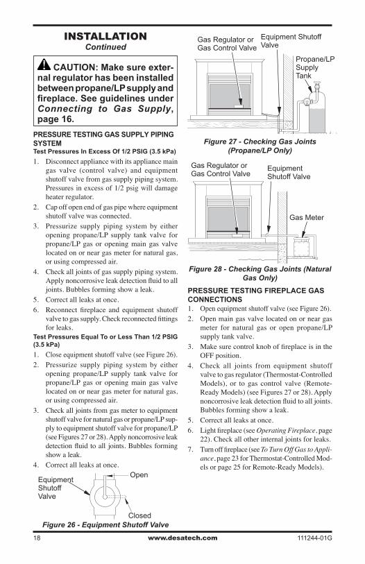
Test Pressures Equal To or Less Than 1/2 PSIG (3.5 kPa)
1. Close equipment shutoff valve (see Figure 26).2. Pressurize supply piping system by either
opening propane/LP supply tank valve for propane/LP gas or opening main gas valve located on or near gas meter for natural gas, or using compressed air.
3. Check all joints from gas meter to equipment shutoff valve for natural gas or propane/LP sup-ply to equipment shutoff valve for propane/LP (see Figures 27 or 28). Apply noncorrosive leak detection fluid to all joints. Bubbles forming show a leak.
4. Correct all leaks at once.
PRESSURE TESTING FIREPLACE GAS CONNECTIONS1. Open equipment shutoff valve (see Figure 26).2. Open main gas valve located on or near gas
meter for natural gas or open propane/LP supply tank valve.
3. Make sure control knob of fireplace is in the OFF position.
4. Check all joints from equipment shutoff valve to gas regulator (Thermostat-Controlled Models), or to gas control valve (Remote-Ready Models) (see Figures 27 or 28). Apply noncorrosive leak detection fluid to all joints. Bubbles forming show a leak.
5. Correct all leaks at once.6. Light fireplace (see Operating Fireplace, page
22). Check all other internal joints for leaks.7. Turn off fireplace (see To Turn Off Gas to Appli-
ance, page 23 for Thermostat-Controlled Mod-els or page 25 for Remote-Ready Models).
Figure 27 - Checking Gas Joints (Propane/LP Only)
Propane/LP Supply Tank
Equipment Shutoff Valve
Equipment Shutoff Valve
Gas Meter
Figure 28 - Checking Gas Joints (Natural Gas Only)
Gas Regulator orGas Control Valve
Figure 26 - Equipment Shutoff Valve
Open
Closed
Equipment Shutoff Valve
Gas Regulator orGas Control Valve
www.desatech.com111244-01G 19
OPTIONAL WIRELESS HAND-HELD REMOTE CONTROL ACCESSORIES
Remote-Ready Models Only (HRC100 Series & HRC200 Series)
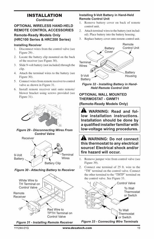
Installing Receiver1. Disconnect wires from the control valve (see
Figure 29) .2. Locate the battery clip mounted on the back
of the receiver (see Figure 30). 3. Slide 9-volt battery (not included) through the
clip.4. Attach the terminal wires to the battery (see
Figure 30). 5. Connect wires from remote receiver to control
valve as shown in Figure 31.6. Install remote receiver unit onto remote/
blower bracket using screws provided (see Figure 31).
Installing 9-Volt Battery in Hand-Held Remote Control Unit 1. Remove battery cover on back of remote
control unit.2. Attach terminal wires to the battery (not includ-
ed). Place battery into the battery housing.3. Replace battery cover onto remote control unit.
iNsTallaTioNContinued
Figure 29 - Disconnecting Wires From Control Valve
Figure 30 - Attaching Battery to Receiver
Battery Clip
9-Volt Battery
Receiver
Terminal Wires
Figure 31 - Installing Remote Receiver
Remote Receiver
White Wire to TH Terminal on Control Valve
Red Wire to TPTH Terminal on Control Valve
Figure 32 - Installing Battery in Hand-Held Remote Control Unit
Battery Cover
9-Volt Battery
Terminal Wires
Remote Control Unit
Battery Housing
OPTIONAL WALL MOUNTED THERMOSTAT - GWMT1
(Remote-Ready Models Only)
WARNING: Read and fol-low installation instructions. Installation should be done by a qualified installer familiar with low-voltage wiring procedures.
WARNING: Do not connect this thermostat to any electrical source! Electrical shock and/or fire hazard will occur.
1. Remove jumper wire from control valve (see Figure 39).
2. Connect one terminal of 25 ft. wire to the “TH” terminal on the control valve. Connect the other terminal to the “THTP” terminal on the control valve. See Figure 33.
Figure 33 - Connecting Wire Terminals
To Wall Thermostat or Switch
To Wall Thermostat or Switch
Control Valve
www.desatech.com 111244-01G20
iNsTallaTioNContinued
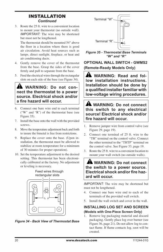
3. Route the 25 ft. wire to a convenient location to mount your thermostat (no outside wall). IMPORTANT: The wire may be shortened but must not be lengthened.
The thermostat should be mounted 54" above the floor in a location where there is good air circulation. Avoid heat sources such as lamps, direct sunlight, fireplace, or heat and air conditioning ducts.
4. Gently remove the cover of the thermostat from the base. Grasp the sides of the cover firmly and pull to separate from the base.
5. Feed the electrical wires through the rectangular slots on each side of the base (see Figure 34).
WARNING: Do not con-nect the thermostat to a power source. Electrical shock and/or a fire hazard will occur.
6. Connect one bare wire end to each terminal (“W” and “R”) of the thermostat base (see Figure 35).
7. Install the base onto the wall with the provided screws.
8. Move the temperature adjustment back and forth to insure the bimetal is free from restrictions.
9. Replace the cover onto the base. (Upon in-stallation, the thermostat must be allowed to stabilize at room temperature for a minimum of 30 minutes for proper operation).
10. Set the temperature adjustment to the desired setting. This thermostat has been electroni-cally calibrated at the factory. No adjustment or leveling is necessary.
Figure 34 - Back View of Thermostat Base
Feed wires through rectangular slots
W
R
Figure 35 - Thermostat Base Terminals “W” and “R”
Terminal “W”
Terminal “R”
OPTIONAL WALL SWITCH - GWMS2
(Remote-Ready Models Only)
WARNING: Read and fol-low installation instructions. Installation should be done by a qualified installer familiar with low-voltage wiring procedures.
WARNING: Do not connect this switch to any electrical source! Electrical shock and/or fire hazard will occur.
1. Remove jumper wire from control valve (see Figure 29, page 19).
2. Connect one terminal of 25 ft. wire to the “TH” terminal on the control valve. Connect the other terminal to the “THTP” terminal on the control valve. See Figure 33, page 19.
3. Route the 25 ft. wire to a convenient location to mount your wall switch (no outside walls).
WARNING: Do not connect the switch to a power source. Electrical shock and/or fire haz-ard will occur.
IMPORTANT: The wire may be shortened but must not be lengthened.4. Connect one bare wire end to each of the
terminals of the provided wall switch.5. Install the wall switch and cover in the wall.
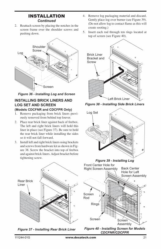
INSTALLING LOG SET AND SCREEN (Models with One-Piece Screen Only)1. Remove log packaging material and discard
packaging. Gently place log over burner (see Figure 36, page 21). Do not allow log to con-tact flame. If flame contacts log, soot will be created.
www.desatech.com111244-01G 21
2. Reattach screen by placing the notches in the screen frame over the shoulder screws and pushing down.
iNsTallaTioNContinued
Log
Shoulder Screw
Screen
Figure 36 - Installing Log and Screen
INSTALLING BRICK LINERS AND LOG SET AND SCREEN(Models CDCFNR and CDCFPR Only)1. Remove packaging from brick liners previ-
ously removed from behind top louver.2. Place rear brick liner against back of firebox.
The left and right brick liners will hold this liner in place (see Figure 37). Be sure to hold the rear brick liner while installing the sides so it will not fall forward.
3. Install left and right brick liners using brackets and screws from hardware kit as shown in Fig-ure 38. Screw the bracket into top of firebox and against brick liners. Adjust bracket before tightening screw.
Figure 37 - Installing Rear Brick Liner
Figure 38 - Installing Side Brick Liners
Figure 39 - Installing Log
Left Brick Liner
Brick Liner Bracket and Screw
Rear Brick Liner
Log Set
4. Remove log packaging material and discard. Gently place log over burner (see Figure 39). (Do not allow log to contact flame as this will create sooting.)
5. Insert each rod through ten rings located at top of screen (see Figure 40).
Figure 40 - Installing Screen for Models CDCFNR/CDCFPR
Screen
Screen Rod
Rings
ScreenAssembly
Front Center Hole for Right Screen Assembly Back Center
Hole for Left Screen Assembly
www.desatech.com 111244-01G22
LIGHTING INSTRUCTIONS
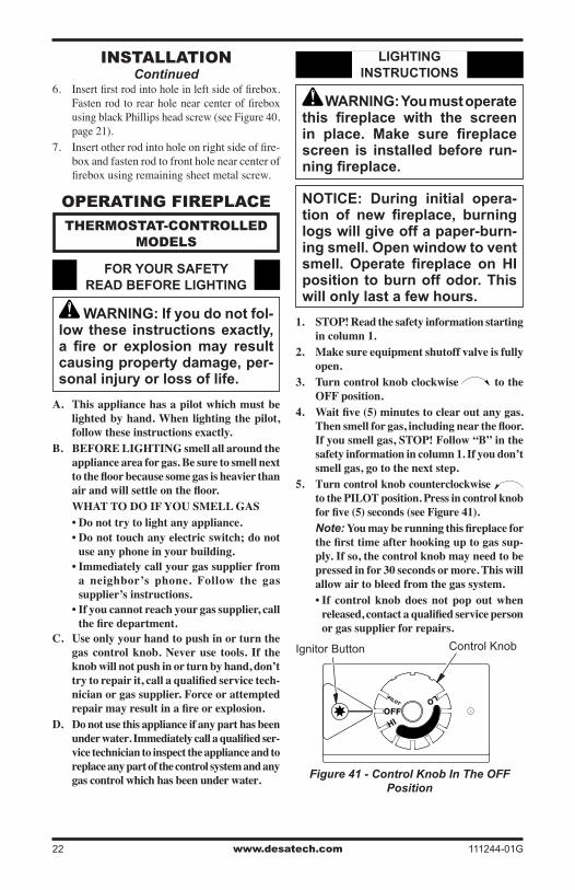
WARNING: You must operate this fireplace with the screen in place. Make sure fireplace screen is installed before run-ning fireplace.
NOTICE: During initial opera-tion of new fireplace, burning logs will give off a paper-burn-ing smell. Open window to vent smell. Operate fireplace on HI position to burn off odor. This will only last a few hours.
1. STOP! Read the safety information starting in column 1.
2. Make sure equipment shutoff valve is fully open.
3. Turn control knob clockwise to the OFF position.
4. Waitfive(5)minutestoclearoutanygas.Thensmellforgas,includingnearthefloor.If you smell gas, STOP! Follow “B” in the safety information in column 1. If you don’t smell gas, go to the next step.
5. Turn control knob counterclockwise to the PILOT position. Press in control knob forfive(5)seconds(seeFigure41).
Note: Youmayberunningthisfireplaceforthefirsttimeafterhookinguptogassup-ply. If so, the control knob may need to be pressed in for 30 seconds or more. This will allow air to bleed from the gas system.• If control knob does not pop out when released,contactaqualifiedservicepersonor gas supplier for repairs.
Figure 41 - Control Knob In The OFF Position
Ignitor Button Control Knob
opERaTiNG FiREplaCE
THERmosTaT-CoNTRollED moDEls
FOR YOUR SAFETY READ BEFORE LIGHTING
WARNING: If you do not fol-low these instructions exactly, a fire or explosion may result causing property damage, per-sonal injury or loss of life.
A. This appliance has a pilot which must be lighted by hand. When lighting the pilot, follow these instructions exactly.
B. BEFORE LIGHTING smell all around the appliance area for gas. Be sure to smell next tothefloorbecausesomegasisheavierthanairandwillsettleonthefloor.
WHAT TO DO IF YOU SMELL GAS• Do not try to light any appliance.• Do not touch any electric switch; do not
use any phone in your building.• Immediately call your gas supplier from
a neighbor’s phone. Follow the gas supplier’s instructions.
• If you cannot reach your gas supplier, call thefiredepartment.
C. Use only your hand to push in or turn the gas control knob. Never use tools. If the knob will not push in or turn by hand, don’t trytorepairit,callaqualifiedservicetech-nician or gas supplier. Force or attempted repairmayresultinafireorexplosion.
D. Do not use this appliance if any part has been underwater.Immediatelycallaqualifiedser-vice technician to inspect the appliance and to replace any part of the control system and any gas control which has been under water.
iNsTallaTioNContinued
6. Insert first rod into hole in left side of firebox. Fasten rod to rear hole near center of firebox using black Phillips head screw (see Figure 40, page 21).
7. Insert other rod into hole on right side of fire-box and fasten rod to front hole near center of firebox using remaining sheet metal screw.

www.desatech.com111244-01G 23
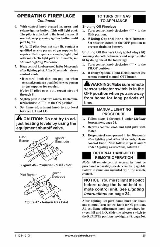
6. With control knob pressed in, press and release ignitor button. This will light pilot. The pilot is attached to the front burner. If needed, keep pressing ignitor button until pilot lights.
Note: If pilot does not stay lit, refer to Troubleshooting, page 30. Also, contact a qualifiedservicepersonorgassupplierforrepairs. Until repairs are made, light pilot with match. To light pilot with match, see Manual Lighting Procedure.
7. Keep control knob pressed in for 30 seconds after lighting pilot. After 30 seconds, release control knob.
Note: If pilot goes out, repeat steps 3 through7.Thisfireplacehasasafetyinter-locksystem.Waitone(1)minuteforsystemto reset before lighting pilot again.
8. Turn control knob counterclockwise to desired heating level. The burner should light. Set control knob to any heat level between HI and LO.
CAUTION: Do not try to ad-just heating levels by using the equipment shutoff valve.
opERaTiNG FiREplaCEContinued
Figure 43 -Propane/LP Gas Pilot
ThermocoupleIgnitor Electrode Pilot Burner
Thermocouple
Ignitor Electrode
Pilot Burner
TO TURN OFF GAS TO APPLIANCE
Shutting Off Fireplace1. Turn control knob clockwise to the
OFF position.2. Turnoffallelectricpowertotheappliance(if
applicable)ifserviceistobeperformed.
Shutting Off Burners Only (pilot stays lit)Turn control knob clockwise to the PILOT position.
THERMOSTAT CONTROL OPERATION
Thethermostatusedonthisfireplacesensestheroom temperature. At times the room may exceed the set temperature. If so, the burner will shut off. The burner will cycle back on when room tem-perature drops below the set temperature. The control knob can be set to any heat level between HI and LO.Note: The thermostat sensing bulb measures the air near thefireplace cabinet.Thismaynotalwaysagreewithroomtemperature(de-pending on housing construction, installation location, room size, open air temperatures, etc.).Frequentuseofyourfireplacewillletyoudetermine your own comfort levels.
MANUAL LIGHTING PROCEDURE
1. Follow steps 1 through5underLighting Instructions, page 22.
2. With control knob pressed in, strike match. Hold match to pilot until pilot lights.
3. Keep control knob pressed in for 30 seconds after lighting pilot. After 30 seconds, release control knob. Now follow step 8 under Lighting Instructions, column 1.
OPERATING BLOWER
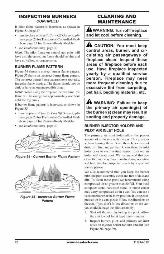
This blower has three settings: ON, OFF, and AUTO. In the ON position, the blower will oper-ate constantly. In the OFF position, the blower will not operate. In the AUTO position, the blower will start when the thermostat senses a sufficientincreaseinfireboxtemperature.Note:Yourfireplace and thermostatblowerwill not turn on and off at the same time. The fireplacemayrunforseveralminutesbeforetheblower turns on. After the heater modulates to the pilot position, the blower will continue to run.Theblowerwillshutoffafterthefireboxtemperature decreases.
Figure 42 - Natural Gas Pilot
www.desatech.com 111244-01G24
opERaTiNG FiREplaCEContinued
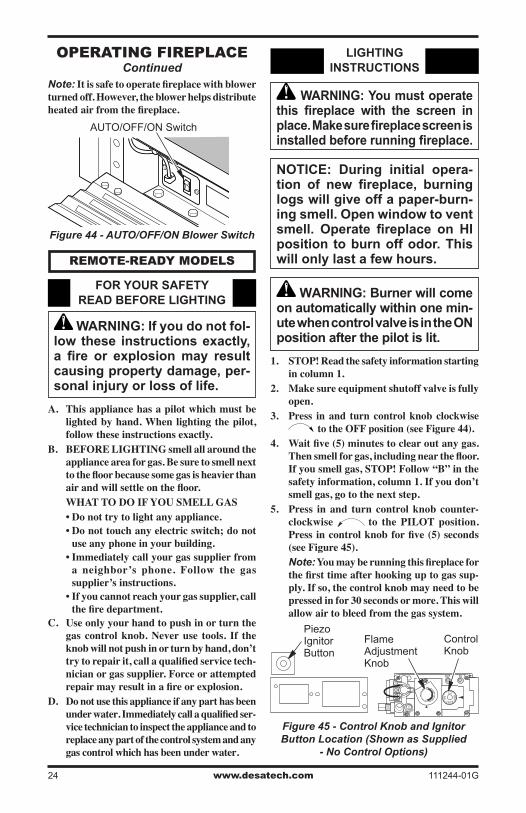
Note:Itissafetooperatefireplacewithblowerturned off. However, the blower helps distribute heatedairfromthefireplace.
Figure 44 - AUTO/OFF/ON Blower Switch
AUTO/OFF/ON Switch
REmoTE-REaDy moDEls
FOR YOUR SAFETY READ BEFORE LIGHTING
WARNING: If you do not fol-low these instructions exactly, a fire or explosion may result causing property damage, per-sonal injury or loss of life.
A. This appliance has a pilot which must be lighted by hand. When lighting the pilot, follow these instructions exactly.
B. BEFORE LIGHTING smell all around the appliance area for gas. Be sure to smell next tothefloorbecausesomegasisheavierthanairandwillsettleonthefloor.
WHAT TO DO IF YOU SMELL GAS• Do not try to light any appliance.• Do not touch any electric switch; do not
use any phone in your building.• Immediately call your gas supplier from
a neighbor’s phone. Follow the gas supplier’s instructions.
• If you cannot reach your gas supplier, call thefiredepartment.
C. Use only your hand to push in or turn the gas control knob. Never use tools. If the knob will not push in or turn by hand, don’t trytorepairit,callaqualifiedservicetech-nician or gas supplier. Force or attempted repairmayresultinafireorexplosion.
D. Do not use this appliance if any part has been underwater.Immediatelycallaqualifiedser-vice technician to inspect the appliance and to replace any part of the control system and any gas control which has been under water.
LIGHTING INSTRUCTIONS
WARNING: You must operate this fireplace with the screen in place. Make sure fireplace screen is installed before running fireplace.
NOTICE: During initial opera-tion of new fireplace, burning logs will give off a paper-burn-ing smell. Open window to vent smell. Operate fireplace on HI position to burn off odor. This will only last a few hours.
WARNING: Burner will come on automatically within one min-ute when control valve is in the ON position after the pilot is lit.
1. STOP! Read the safety information starting in column 1.
2. Make sure equipment shutoff valve is fully open.
3. Press in and turn control knob clockwise totheOFFposition(seeFigure44).
4. Waitfive(5)minutestoclearoutanygas.Thensmellforgas,includingnearthefloor.If you smell gas, STOP! Follow “B” in the safety information, column 1. If you don’t smell gas, go to the next step.
5. Press in and turn control knob counter-clockwise to the PILOT position. Pressincontrolknobforfive(5)seconds(seeFigure45).
Note:Youmayberunningthisfireplaceforthefirsttimeafterhookinguptogassup-ply. If so, the control knob may need to be pressed in for 30 seconds or more. This will allow air to bleed from the gas system.
Figure 45 - Control Knob and Ignitor Button Location (Shown as Supplied
- No Control Options)
Piezo Ignitor Button
Control Knob
Flame Adjustment Knob
www.desatech.com111244-01G 25
opERaTiNG FiREplaCEContinued
6. With control knob pressed in, press and release ignitor button. This will light pilot. The pilot is attached to the front burner. If needed, keep pressing ignitor button until pilot lights.
Note: If pilot does not stay lit, contact a qualifiedservicepersonorgassupplierforrepairs. Until repairs are made, light pilot with match. To light pilot with match, see Manual Lighting Procedure.
7. Keep control knob pressed in for 30 seconds after lighting pilot. After 30 seconds, release control knob.• If control knob does not pop out when released,contactaqualifiedservicepersonor gas supplier for repairs.
Note: If pilot goes out, repeat steps 4 through 8.
8. Slightly push in and turn control knob coun-terclockwise to the ON position.
9. Set flame adjustment knob to any levelbetween HI and LO.
CAUTION: Do not try to ad-just heating levels by using the equipment shutoff valve.
Figure 46 - Propane/LP Gas Pilot
Ignitor Electrode
Pilot Burner
Figure 47 - Natural Gas Pilot
Ignitor Electrode
Pilot Burner
TO TURN OFF GAS TO APPLIANCE
Shutting Off Fireplace1. Turn control knob clockwise to the
OFF position.2. If Using Optional Hand-Held Remote:
Set selector switch in the OFF position to prevent draining battery.
Shutting Off Burners Only (pilot stays lit)You may shut off the burners and keep the pilot lit by doing one of the following: 1. Turn control knob clockwise to the
PILOT position.2. If Using Optional Hand-Held Remote: Use
remote control manual OFF button.
WARNING: Make sure remote sensor selector switch is in the OFF position when you are away from home for long periods of time.
MANUAL LIGHTING PROCEDURE
1. Follow steps 1 through5underLighting Instructions, page 24.
2. Depress control knob and light pilot with match.
3. Keep control knob pressed in for 30 seconds after lighting pilot. After 30 seconds, release control knob. Now follow steps 8 and 9 under Lighting Instructions, column 1.
OPTIONAL HAND-HELD REMOTE OPERATION
Note: All remote control accessories must be purchasedseparately(seeAccessories,page44).Follow instructions included with the remote control.
NOTICE: You must light the pilot before using the hand-held re-mote control unit. See Lighting Instructions on page 24.
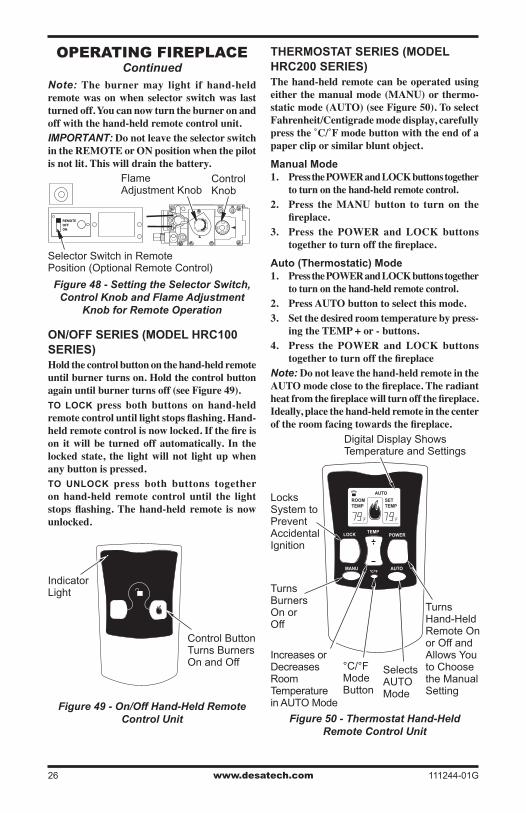
After lighting, letpilotflameburn foraboutone minute. Turn control knob to ON position. Adjustflameadjustmentknobanywherebe-tween HI and LO. Slide the selector switch to theREMOTEposition(seeFigure48,page26).
www.desatech.com 111244-01G26
REMOTEOFFON
HI
LO
INOUT
opERaTiNG FiREplaCEContinued
Note: The burner may light if hand-held remote was on when selector switch was last turned off. You can now turn the burner on and off with the hand-held remote control unit. IMPORTANT: Do not leave the selector switch in the REMOTE or ON position when the pilot is not lit. This will drain the battery.
ON/OFF SERIES (MODEL HRC100 SERIES)Hold the control button on the hand-held remote until burner turns on. Hold the control button againuntilburnerturnsoff(seeFigure49).TO LOCK press both buttons on hand-held remotecontroluntillightstopsflashing.Hand-heldremotecontrolisnowlocked.Ifthefireison it will be turned off automatically. In the locked state, the light will not light up when any button is pressed. TO UNLOCK press both buttons together on hand-held remote control until the light stopsflashing.Thehand-held remote is nowunlocked.
Figure 48 - Setting the Selector Switch, Control Knob and Flame Adjustment
Knob for Remote Operation
Flame Adjustment Knob
Control Knob
Selector Switch in RemotePosition (Optional Remote Control)
Figure 49 - On/Off Hand-Held Remote Control Unit
Control Button Turns Burners On and Off
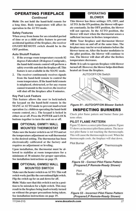
THERMOSTAT SERIES (MODEL HRC200 SERIES)The hand-held remote can be operated using eitherthemanualmode(MANU)orthermo-staticmode(AUTO)(seeFigure50).ToselectFahrenheit/Centigrade mode display, carefully pressthe˚C/˚Fmodebuttonwiththeendofapapercliporsimilarbluntobject.
Manual Mode1. Press the POWER and LOCK buttons together
to turn on the hand-held remote control.2. Press the MANU button to turn on the
fireplace.3. Press the POWER and LOCK buttons
togethertoturnoffthefireplace.
Auto (Thermostatic) Mode1. Press the POWER and LOCK buttons together
to turn on the hand-held remote control.2. Press AUTO button to select this mode.3. Set the desired room temperature by press-
ing the TEMP + or - buttons.4. Press the POWER and LOCK buttons
togethertoturnoffthefireplaceNote: Do not leave the hand-held remote in the AUTOmodeclosetothefireplace.Theradiantheatfromthefireplacewillturnoffthefireplace.Ideally, place the hand-held remote in the center oftheroomfacingtowardsthefireplace.
IndicatorLight
Figure 50 - Thermostat Hand-Held Remote Control Unit
LOCK
MANU AUTOºC/ºF
TEMPPOWER
ROOMTEMP
SETTEMP
AUTO
Turns Hand-Held Remote On or Off and Allows You to Choose the Manual Setting
Selects AUTO Mode
°C/°F Mode Button
Locks System to Prevent Accidental Ignition
Turns Burners On or Off
Increases or Decreases Room Temperature in AUTO Mode
Digital Display Shows Temperature and Settings
www.desatech.com111244-01G 27
opERaTiNG FiREplaCEContinued
Note: Do not hold the hand-held remote for a long time. Body temperature will affect its operation in the AUTO mode.
Safety FeaturesWhen away from home for an extended period of time or as a child safety feature to prevent accidentalignitionofthefireplace,thereceiverON/OFF/REMOTE switch should be in the OFF position.
Auto Shutoff Feature1. If the average room temperature exceeds 82
degreesFahrenheit(28degreesCentigrade),the hand-held remote control will perform a safetyoverrideandshutthefireplaceoff.Thisfeature is not available in the MANU mode.
2. The receiver continuously receives signals from the hand-held remote to control the room temperature. If the hand-held remote is misplaced, obstructed, or for any reason cannot transmit to the receiver, the receiver willshutoffthefireplaceafter8minutes.
Key Pad Lock FeatureThis feature allows the user to lock/unlock the keypad on the hand-held remote in the MANU or AUTO mode to prevent inadvertent operation(i.e.childrenoperatingthehand-heldremotecontrol,etc.).Thekeypadislockedineither on or off. Press the POWER and LOCK buttons together to turn the unit on or off.
Figure 51 - AUTO/OFF/ON Blower Switch
OPTIONAL GWMT1 WALL MOUNTED THERMOSTAT
Make sure the heater switch is on AUTO and set thetemperatureadjustmentonwallthermostatto the desired setting. The thermostat has been electronically calibrated at the factory and requiresnoadjustmentorleveling.Upon installation, the thermostat must be al-lowed to stabilize at room temperature for a minimum of 30 minutes for proper operation. See installation instructions on page 19.
OPTIONAL GWMS2 WALL MOUNTED SWITCH
Make sure the heater switch is on AUTO. This wall switchworksjustliketheconventionallightswitch.Flip the switch up for on and down for off.Note: Make sure that this switch is not in a posi-tion to be mistaken for a light switch. This may resultinthefireplacebeinginadvertentlyturnedon without the proper precautions being taken. See installation instructions on page 19.
OPERATING BLOWER
This blower has three settings: ON, OFF, and AUTO. In the ON position, the blower will oper-ate constantly. In the OFF position, the blower will not operate. In the AUTO position, the blower will start when the thermostat senses a sufficientincreaseinfireboxtemperature.Note:Yourfireplace and thermostatblowerwill not turn on and off at the same time. The fireplacemayrunforseveralminutesbeforetheblower turns on. After the heater modulates to the pilot position, the blower will continue to run.Theblowerwillshutoffafterthefireboxtemperature decreases.Note:Itissafetooperatefireplacewithblowerturned off. However, the blower helps distribute heatedairfromthefireplace.
AUTO/OFF/ON Switch
iNspECTiNG BURNERsCheck pilot flame pattern and burner flame pat-terns often.PILOT FLAME PATTERNFigure 52 shows a correct pilot flame pattern. Figure 53 shows an incorrect pilot flame pattern. The incor-rect pilot flame is not touching the thermocouple. This will cause the thermocouple to cool. When the thermocouple cools, the fireplace will shut down.
Figure 52 - Correct Pilot Flame Pattern (Propane/LP Remote-Ready Shown)
Pilot BurnerThermocouple
Figure 53 - Incorrect Pilot Flame Pattern (Propane/LP Remote-Ready Shown)
Thermocouple
Pilot Burner
www.desatech.com 111244-01G28
If pilot flame pattern is incorrect, as shown in Figure 53, page 27• turn fireplace off (see To Turn Off Gas to Appli-
ance, page 23 for Thermostat-Controlled Mod-els or page 25 for Remote-Ready Models)
• see Troubleshooting, page 30Note: The pilot flame on natural gas units will have a slight curve, but flame should be blue and have no yellow or orange color.
BURNER FLAME PATTERNFigure 54 shows a correct burner flame pattern. Figure 55 shows an incorrect burner flame pattern. The incorrect burner flame pattern shows sporadic, irregular flame tipping. The flame should not be dark or have an orange/reddish tinge.Note: When using the fireplace the first time, the flame will be orange for approximately one hour until the log cures. If burner flame pattern is incorrect, as shown in Figure 55• turn fireplace off (see To Turn Off Gas to Appli-
ance, page 23 for Thermostat-Controlled Mod-els or page 25 for Remote-Ready Models)
• see Troubleshooting, page 30
ClEaNiNG aND maiNTENaNCE
WARNING: Turn off fireplace and let cool before cleaning.
CAUTION: You must keep control areas, burner, and cir-culating air passageways of fireplace clean. Inspect these areas of fireplace before each use. Have fireplace inspected yearly by a qualified service person. Fireplace may need more frequent cleaning due to excessive lint from carpeting, pet hair, bedding material, etc.
WARNING: Failure to keep the primary air opening(s) of the burner(s) clean may result in sooting and property damage.
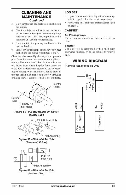
BURNER INjECTOR HOLDER AND PILOT AIR INLET HOLEThe primary air inlet holes allow the proper amount of air to mix with the gas. This provides a clean burning flame. Keep these holes clear of dust, dirt, lint, and pet hair. Clean these air inlet holes prior to each heating season. Blocked air holes will create soot. We recommend that you clean the unit every three months during operation and have fireplace inspected yearly by a qualified service person.We also recommend that you keep the burner tube and pilot assembly clean and free of dust and dirt. To clean these parts we recommend using compressed air no greater than 30 PSI. Your local computer store, hardware store, or home center may carry compressed air in a can. You can use a vacuum cleaner in the blow position. If using com-pressed air in a can, please follow the directions on the can. If you don’t follow directions on the can, you could damage the pilot assembly.1. Shut off the unit, including the pilot. Allow
the unit to cool for at least thirty minutes.2. Inspect burner, pilot, and primary air inlet
holes on injector holder for dust and dirt (see Figure 56, page 29).
iNspECTiNG BURNERsCONTINUED
Figure 54 - Correct Burner Flame Pattern
Figure 55 - Incorrect Burner Flame Pattern
www.desatech.com111244-01G 29
Figure 56 - Injector Holder On Outlet Burner Tube
Burner Tube
Injector Holder
Primary Air Inlet Holes
3. Blow air through the ports/slots and holes in the burner.
4. Check the injector holder located at the end of the burner tube again. Remove any large particles of dust, dirt, lint, or pet hair with a soft cloth or vacuum cleaner nozzle.
5. Blow air into the primary air holes on the injector holder.
6. In case any large clumps of dust have now been pushed into the burner repeat steps 3 and 4.
Clean the pilot assembly also. A yellow tip on the pilot flame indicates dust and dirt in the pilot as-sembly. There is a small pilot air inlet hole about two inches from where the pilot flame comes out of the pilot assembly (see Figures 57 or 58 depend-ing on model). With the unit off, lightly blow air through the air inlet hole. You may blow through a drinking straw if compressed air is not available.
ClEaNiNG aND maiNTENaNCE
Continued
Figure 57 - Pilot Inlet Air Hole(Propane/LP Gas)
Pilot Assembly
Pilot Air Inlet Hole
Pilot Assembly
Pilot Air Inlet Hole
Figure 58 - Pilot Inlet Air Hole (Natural Gas)
WiRiNG DiaGRam(Remote-Ready Models Only)
Sw
itch
Bla
ckA
uto
Off
On
Red
Red
Whi
teT
herm
opile
Gas
Con
trol
T
PT
HT
H
TP
TH
TP
LOG SET• If you remove one-piece log set for cleaning,
refer to page 21, for placement instructions.• Replace log set if broken or chipped (dime-sized
or larger).
CABINET
Air PassagewaysUse a vacuum cleaner or pressurized air to clean.
ExteriorUse a soft cloth dampened with a mild soap and water mixture. Wipe the cabinet to remove dust.
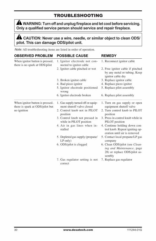
www.desatech.com 111244-01G30
TRoUBlEsHooTiNG
WARNING: Turn off and unplug fireplace and let cool before servicing. Only a qualified service person should service and repair fireplace.
CAUTION: Never use a wire, needle, or similar object to clean ODS/pilot. This can damage ODS/pilot unit.
Note: All troubleshooting items are listed in order of operation.
POSSIBLE CAUSE
1. Ignitor electrode not con-nected to ignitor cable
2. Ignitor cable pinched or wet
3. Broken ignitor cable4. Bad piezo ignitor5. Ignitor electrode positioned
wrong6. Ignitor electrode broken
1. Gas supply turned off or equip-ment shutoff valve closed
2. Control knob not in PILOT position
3. Control knob not pressed in while in PILOT position
4. Air in gas lines when in-stalled
5. Depleted gas supply (propane/LP only)
6. ODS/pilot is clogged
7. Gas regulator setting is not correct
REMEDY
1. Reconnect ignitor cable
2. Free ignitor cable if pinched by any metal or tubing. Keep ignitor cable dry
3. Replace ignitor cable4. Replace piezo ignitor 5. Replace pilot assembly
6. Replace pilot assembly
1. Turn on gas supply or open equipment shutoff valve
2. Turn control knob to PILOT position
3. Press in control knob while in PILOT position
4. Continue holding down con-trol knob. Repeat igniting op-eration until air is removed
5. Contact local propane/LP gas company
6. Clean ODS/pilot (see Clean-ing and Maintenance, page 28) or replace ODS/pilot as-sembly
7. Replace gas regulator
OBSERVED PROBLEM
When ignitor button is pressed, there is no spark at ODS/pilot
When ignitor button is pressed, there is spark at ODS/pilot but no ignition

www.desatech.com111244-01G 31
POSSIBLE CAUSE
1. Contro l knob not fu l ly pressed in
2. Control knob not pressed in long enough
3. Safety interlock system has been triggered
4. Equipment shutoff valve not fully open
5. Pilot flame not touching ther-mocouple, which allows ther-mocouple to cool, causing pilot flame to go out. This problem could be caused by one or both of the following:
A) Low gas pressure B) Dirty or partially clogged
ODS/pilot 6. Thermocouple connection
loose at control valve 7. Thermocouple damaged8. Control valve damaged
1. Inlet gas pressure is too low
2. Burner orifice is clogged
3. Thermopile leads disconnected or improperly connected (Re-mote-Ready Models Only)
4. Burners will not come on in re-mote position (Remote-Ready Models Only)
1. Manifold pressure is too low
2. Burner orifice is clogged
1. Burner orifice is clogged or damaged
2. Damaged burner3. Gas regulator defective4. Inlet gas pressure is too low
REMEDY
1. Press in control knob fully
2. After ODS/pilot lights, keep control knob pressed in 30 seconds
3. Wait one minute for safety in-terlock system to reset. Repeat ignition operation
4. Fully open equipment shutoff valve
5. A) Contact local natural or propane/LP gas company
B) Clean ODS/pilot (see
Cleaning and Maintenance, page 28) or replace ODS/pilot assembly
6. Hand tighten until snug, then tighten 1/4 turn more
7. Replace pilot assembly8. Replace control valve
1. Contact local natural or pro-pane/LP gas company
2. Clean burner (see Cleaning and Maintenance, page 28) or replace burner orifice
3. Reconnect leads (see Wiring Diagram, page 29)
4. Replace battery in transmitter and receiver
1. Contact local natural or pro-pane/LP gas company
2. Clean burner (see Cleaning and Maintenance, page 28) or replace burner orifice
1. Clean burner (see Cleaning and Maintenance, page 28) or replace burner orifice
2. Replace damaged burner3. Replace gas regulator4. Contact local natural or pro-
pane/LP gas company
OBSERVED PROBLEM
ODS/pilot lights but flame goes out when control knob is released
Burner does not light after ODS/pilot is lit
Delayed ignition of burner
Burner backfiring during com-bustion
TRoUBlEsHooTiNGContinued
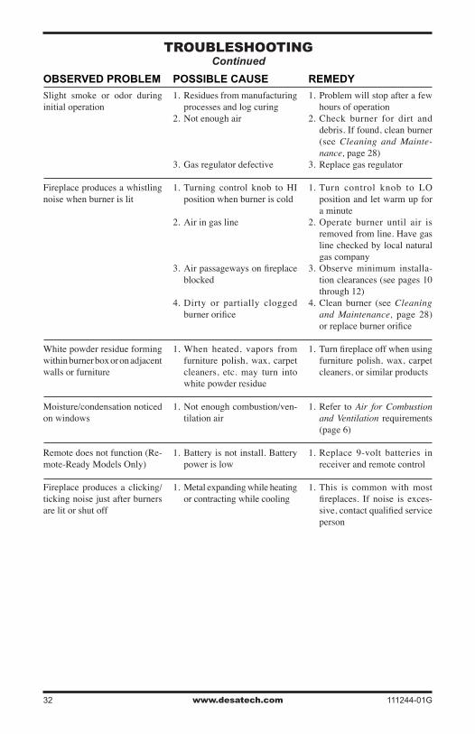
www.desatech.com 111244-01G32
TRoUBlEsHooTiNGContinued
POSSIBLE CAUSE
1. Residues from manufacturing processes and log curing
2. Not enough air
3. Gas regulator defective
1. Turning control knob to HI position when burner is cold
2. Air in gas line
3. Air passageways on fireplace blocked
4. Dirty or partially clogged burner orifice
1. When heated, vapors from furniture polish, wax, carpet cleaners, etc. may turn into white powder residue
1. Not enough combustion/ven-tilation air
1. Battery is not install. Battery power is low
1. Metal expanding while heating or contracting while cooling
REMEDY
1. Problem will stop after a few hours of operation
2. Check burner for dirt and debris. If found, clean burner (see Cleaning and Mainte-nance, page 28)
3. Replace gas regulator
1. Turn control knob to LO position and let warm up for a minute
2. Operate burner until air is removed from line. Have gas line checked by local natural gas company
3. Observe minimum installa-tion clearances (see pages 10 through 12)
4. Clean burner (see Cleaning and Maintenance, page 28) or replace burner orifice
1. Turn fireplace off when using furniture polish, wax, carpet cleaners, or similar products
1. Refer to Air for Combustion and Ventilation requirements (page 6)
1. Replace 9-volt batteries in receiver and remote control
1. This is common with most fireplaces. If noise is exces-sive, contact qualified service person
OBSERVED PROBLEM
Slight smoke or odor during initial operation
Fireplace produces a whistling noise when burner is lit
White powder residue forming within burner box or on adjacent walls or furniture
Moisture/condensation noticed on windows
Remote does not function (Re-mote-Ready Models Only)
Fireplace produces a clicking/ticking noise just after burners are lit or shut off
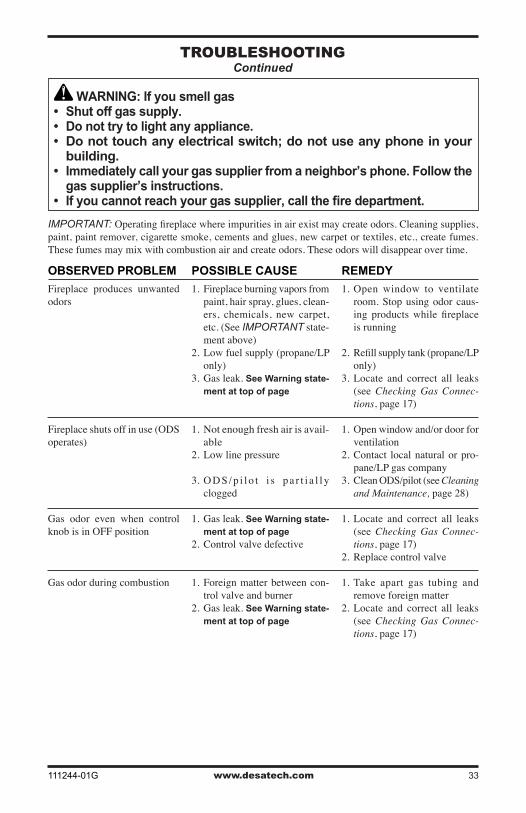
www.desatech.com111244-01G 33
TRoUBlEsHooTiNGContinued
WARNING: If you smell gas• Shut off gas supply.• Do not try to light any appliance.• Do not touch any electrical switch; do not use any phone in your
building.• Immediately call your gas supplier from a neighbor’s phone. Follow the
gas supplier’s instructions.• If you cannot reach your gas supplier, call the fire department.
IMPORTANT: Operating fireplace where impurities in air exist may create odors. Cleaning supplies, paint, paint remover, cigarette smoke, cements and glues, new carpet or textiles, etc., create fumes. These fumes may mix with combustion air and create odors. These odors will disappear over time.
POSSIBLE CAUSE
1. Fireplace burning vapors from paint, hair spray, glues, clean-ers, chemicals, new carpet, etc. (See IMPORTANT state-ment above)
2. Low fuel supply (propane/LP only)
3. Gas leak. See Warning state-ment at top of page
1. Not enough fresh air is avail-able
2. Low line pressure
3. O D S / p i l o t i s p a r t i a l l y clogged
1. Gas leak. See Warning state-ment at top of page
2. Control valve defective
1. Foreign matter between con-trol valve and burner
2. Gas leak. See Warning state-ment at top of page
REMEDY
1. Open window to ventilate room. Stop using odor caus-ing products while fireplace is running
2. Refill supply tank (propane/LP only)
3. Locate and correct all leaks (see Checking Gas Connec-tions, page 17)
1. Open window and/or door for ventilation
2. Contact local natural or pro-pane/LP gas company
3. Clean ODS/pilot (see Cleaning and Maintenance, page 28)
1. Locate and correct all leaks (see Checking Gas Connec-tions, page 17)
2. Replace control valve
1. Take apart gas tubing and remove foreign matter
2. Locate and correct all leaks (see Checking Gas Connec-tions, page 17)
OBSERVED PROBLEM
Fireplace produces unwanted odors
Fireplace shuts off in use (ODS operates)
Gas odor even when control knob is in OFF position
Gas odor during combustion
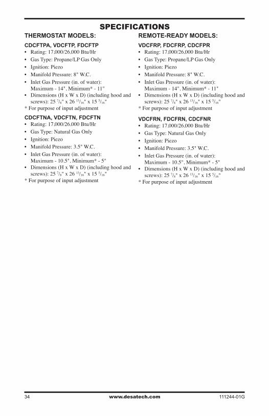
www.desatech.com 111244-01G34
spECiFiCaTioNsTHERMOSTAT MODELS:
CDCFTPA, VDCFTP, FDCFTP• Rating: 17,000/26,000 Btu/Hr• Gas Type: Propane/LP Gas Only• Ignition: Piezo• Manifold Pressure: 8" W.C.• Inlet Gas Pressure (in. of water): Maximum - 14", Minimum* - 11"• Dimensions (H x W x D) (including hood and
screws): 25 7/8" x 26 13/16" x 15 5/16"* For purpose of input adjustment
CDCFTNA, VDCFTN, FDCFTN• Rating: 17,000/26,000 Btu/Hr• Gas Type: Natural Gas Only• Ignition: Piezo• Manifold Pressure: 3.5" W.C.• Inlet Gas Pressure (in. of water): Maximum - 10.5", Minimum* - 5"• Dimensions (H x W x D) (including hood and
screws): 25 7/8" x 26 13/16" x 15 5/16"* For purpose of input adjustment
REMOTE-READY MODELS:
VDCFRP, FDCFRP, CDCFPR• Rating: 17,000/26,000 Btu/Hr• Gas Type: Propane/LP Gas Only• Ignition: Piezo• Manifold Pressure: 8" W.C.• Inlet Gas Pressure (in. of water): Maximum - 14", Minimum* - 11"• Dimensions (H x W x D) (including hood and
screws): 25 7/8" x 26 13/16" x 15 5/16"* For purpose of input adjustment
VDCFRN, FDCFRN, CDCFNR• Rating: 17,000/26,000 Btu/Hr• Gas Type: Natural Gas Only• Ignition: Piezo• Manifold Pressure: 3.5" W.C.• Inlet Gas Pressure (in. of water): Maximum - 10.5", Minimum* - 5"• Dimensions (H x W x D) (including hood and
screws): 25 7/8" x 26 13/16" x 15 5/16"* For purpose of input adjustment
www.desatech.com111244-01G 35
sERViCE HiNTsWhen Gas Pressure Is Too Low• pilot will not stay lit• burners will have delayed ignition• fireplace will not produce specified heat• for propane/LP units, propane/LP gas supply
may be lowYou may feel your gas pressure is too low. If so, con-tact your local natural or propane/LP gas supplier.
TECHNiCal sERViCEYou may have further questions about installation, operation, or troubleshooting. If so, contact DESA Heating Products’ Technical Service Department at 1-866-672-6040. When calling, please have your model and serial numbers of your heater ready.You can also visit DESA Heating Products’ techni-cal services web site at www.desatech.com.
REplaCEmENT paRTsNote: Use only original replacement parts. This will protect your warranty coverage for parts replaced under warranty.
PARTS UNDER WARRANTYContact authorized dealers of this product. If they can’t supply original replacement part(s), call DESA Heating Products’ Technical Service Department at 1-866-672-6040.When calling DESA Heating Products, have ready• your name• your address• model and serial numbers of your fireplace • how fireplace was malfunctioning• type of gas used (propane/LP or natural gas)• purchase dateUsually, we will ask you to return the part to the factory.
PARTS NOT UNDER WARRANTYContact authorized dealers of this product. If they can’t supply original replacement part(s), call DESA Heating Products at 1-866-672-6040 for referral information.When calling DESA Heating Products, have ready• model number of your fireplace • the replacement part number
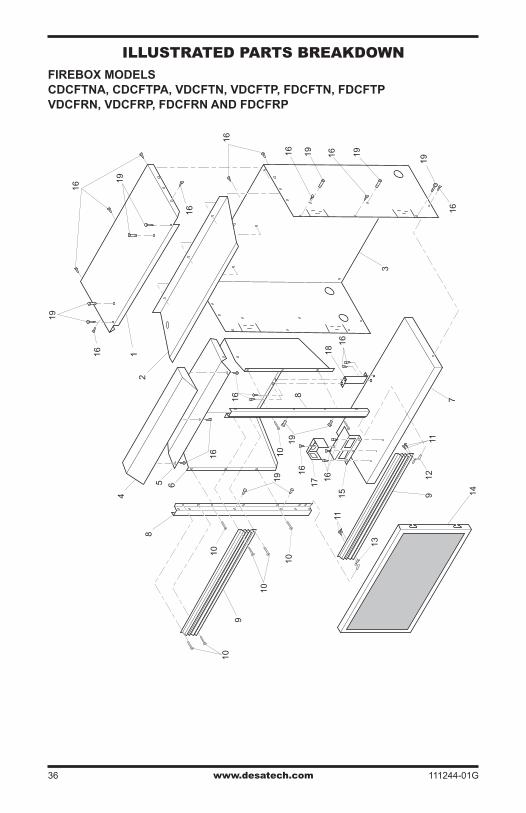
www.desatech.com 111244-01G36
8
8
19
19
1919
19
19
19
1
9
9
10
10
10
16
17
10
10
14
6
3
1112
13
1115
1618
16
16 16
16
16
16
2
5
16
16
16
16
7
4
illUsTRaTED paRTs BREakDoWN
FIREBOx MODELS CDCFTNA, CDCFTPA, VDCFTN, VDCFTP, FDCFTN, FDCFTP VDCFRN, VDCFRP, FDCFRN AND FDCFRP
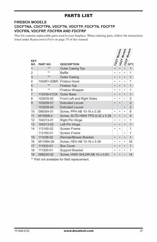
www.desatech.com111244-01G 37
paRTs lisT
FIREBOx MODELS CDCFTNA, CDCFTPA, VDCFTN, VDCFTP, FDCFTN, FDCFTP VDCFRN, VDCFRP, FDCFRN AND FDCFRPThis list contains replaceable parts used in your fireplace. When ordering parts, follow the instructions listed under Replacement Parts on page 35 of this manual.
KEY NO. PART NO. DESCRIPTION QTY.
1 ** Outer Casing Top • • • 12 ** Baffle • • • 13 ** Outer Casing • • • 14 104281-02BR Firebox Hood • • • 15 ** Firebox Top • • • 16 ** Firebox Wrapper • • • 17 110339-01CK Outer Base • • • 18 102635-02 Front Left and Right Sides • • • 29 103209-01 Extruded Louver • • 2
103209-05 Extruded Louver • 210 098304-01 Screw, PPH AB 10-16 x 0.38 • • • 811 M10908-2 Screw, SLTD HWH TPG 6-32 x 0.38 • • • 412 104313-01 Right Pin Hinge • • • 113 104313-02 Left Pin Hinge • • • 114 113160-02 Screen Frame • • 1
113160-01 Screen Frame • 115 111038-02 Remote/Blower Bracket • • • 116 M11084-26 Screw, HEH AB 10-16 x 0.38 • • • 3517 111633-01 Box Cover • • • 118 111200-01 Support Bracket • • • 119 099230-02 Screw, HWH SHLDR AB 10 x 0.63 • • • 14
** Part not available for field replacement.
FD
CF
Mo
del
s
CD
CF
Mo
del
s
VD
CF
Mo
del
s
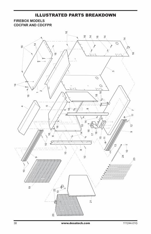
www.desatech.com 111244-01G38
illUsTRaTED paRTs BREakDoWNFIREBOx MODELS CDCFNR AND CDCFPR
8
10
8
14
14
14
14
14
14
14
1 9
9
10 10
20
21
22
10
16
17
10
10
6
3
11
12
13
23
19
24
11
15
16
18 16
16
16
16
16
16
16
2
5
16
16
16
16
7
4
10
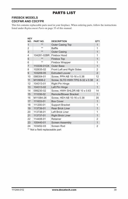
www.desatech.com111244-01G 39
paRTs lisTFIREBOx MODELS CDCFNR AND CDCFPRThis list contains replaceable parts used in your fireplace. When ordering parts, follow the instructions listed under Replacement Parts on page 35 of this manual.
KEY NO. PART NO. DESCRIPTION QTY.
1 ** Outer Casing Top 12 ** Baffle 13 ** Outer Casing 14 104281-02BR Firebox Hood 15 ** Firebox Top 16 ** Firebox Wrapper 17 110339-01CK Outer Base 18 102635-02 Front Left and Right Sides 29 103209-05 Extruded Louver 210 098304-01 Screw, PPH AB 10-16 x 0.38 1211 M10908-2 Screw, SLTD HWH TPG 6-32 x 0.38 412 104313-01 Right Pin Hinge 113 104313-02 Left Pin Hinge 114 099230-02 Screw, HWH SHLDR AB 10 x 0.63 1415 111038-02 Remote/Blower Bracket 116 M11084-26 Screw, HEH AB 10-16 x 0.38 3517 111633-01 Box Cover 118 111200-01 Support Bracket 119 113739-01 Rear Brick Liner 120 113738-01 Left Brick Liner 121 113737-01 Right Brick Liner 122 114408-01 Retainer 223 105440-01 Screen Assembly 124 103452-03 Screen Rod 2** Not a field replaceable part

www.desatech.com 111244-01G40
illUsTRaTED paRTs BREakDoWNTHERMOSTAT MODELS FDCFTP, FDCFTN, VDCFTP, VDCFTN, CDCFTPA AND CDCFTNA
8
7
56
6
12
2
4
19
18
15
16
9
9
17
11
14
3
13
20
9
1
21
10
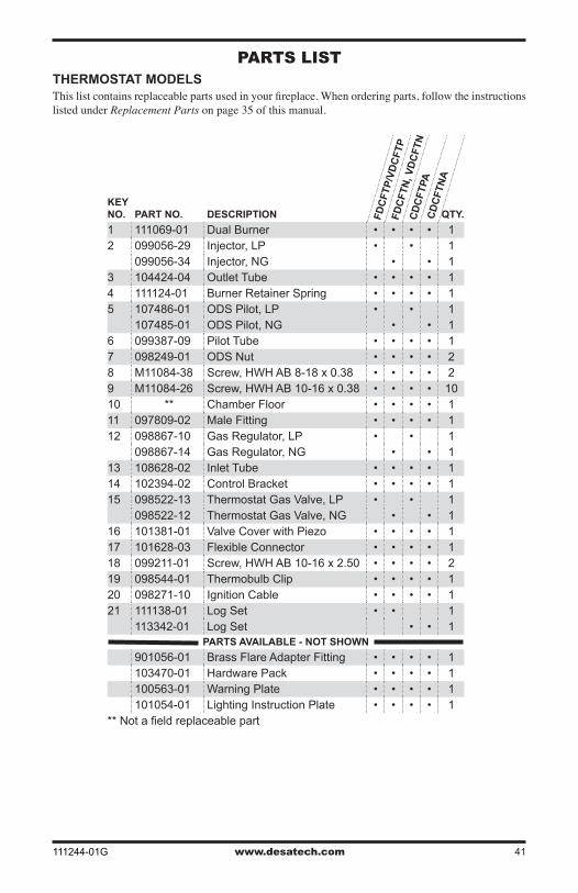
www.desatech.com111244-01G 41
KEY NO. PART NO. DESCRIPTION QTY.
1 111069-01 Dual Burner • • • • 12 099056-29 Injector, LP • • 1
099056-34 Injector, NG • • 13 104424-04 Outlet Tube • • • • 14 111124-01 Burner Retainer Spring • • • • 15 107486-01 ODS Pilot, LP • • 1
107485-01 ODS Pilot, NG • • 16 099387-09 Pilot Tube • • • • 17 098249-01 ODS Nut • • • • 28 M11084-38 Screw, HWH AB 8-18 x 0.38 • • • • 29 M11084-26 Screw, HWH AB 10-16 x 0.38 • • • • 1010 ** Chamber Floor • • • • 111 097809-02 Male Fitting • • • • 112 098867-10 Gas Regulator, LP • • 1
098867-14 Gas Regulator, NG • • 113 108628-02 Inlet Tube • • • • 114 102394-02 Control Bracket • • • • 115 098522-13 Thermostat Gas Valve, LP • • 1
098522-12 Thermostat Gas Valve, NG • • 116 101381-01 Valve Cover with Piezo • • • • 117 101628-03 Flexible Connector • • • • 118 099211-01 Screw, HWH AB 10-16 x 2.50 • • • • 219 098544-01 Thermobulb Clip • • • • 120 098271-10 Ignition Cable • • • • 121 111138-01 Log Set • • 1
113342-01 Log Set • • 1PARTS AVAILABLE - NOT SHOWN
901056-01 Brass Flare Adapter Fitting • • • • 1103470-01 Hardware Pack • • • • 1100563-01 Warning Plate • • • • 1101054-01 Lighting Instruction Plate • • • • 1
** Not a field replaceable part
FD
CF
TP
/VD
CF
TP
CD
CF
TP
A
FD
CF
TN
, VD
CF
TN
CD
CF
TN
A
paRTs lisTTHERMOSTAT MODELSThis list contains replaceable parts used in your fireplace. When ordering parts, follow the instructions listed under Replacement Parts on page 35 of this manual.
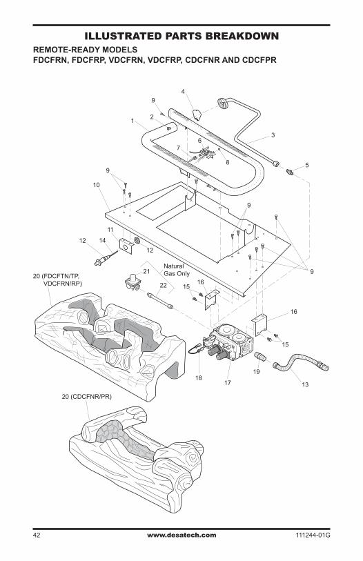
www.desatech.com 111244-01G42
illUsTRaTED paRTs BREakDoWNREMOTE-READY MODELS FDCFRN, FDCFRP, VDCFRN, VDCFRP, CDCFNR AND CDCFPR
O
FF
P
ILOT O
N
H
I
L
O
16
15
1516
12
12
11
9
9
9
10
5
1718
13
19
21
4
3
14
76
8
20 (FDCFTN/TP, VDCFRN/RP)
20 (CDCFNR/PR)
NaturalGas Only
9
21
22
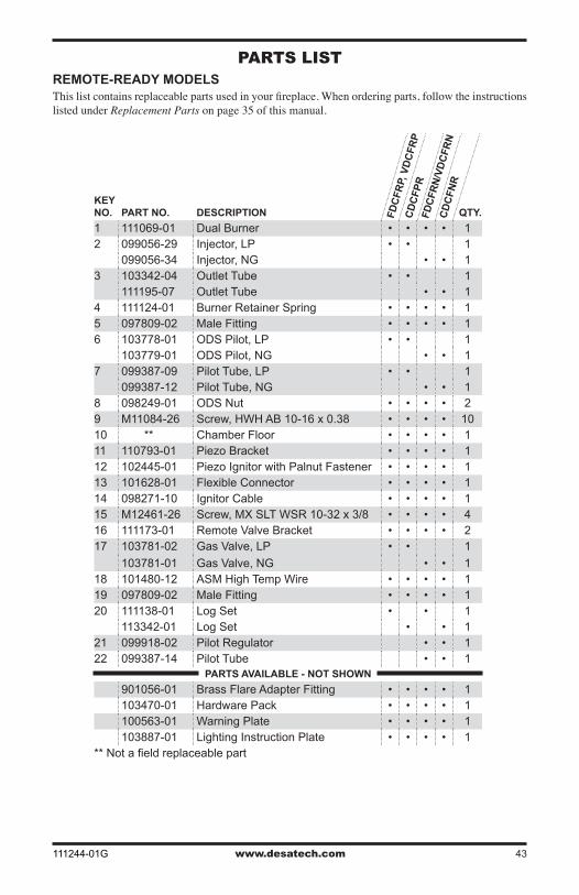
www.desatech.com111244-01G 43
paRTs lisTREMOTE-READY MODELSThis list contains replaceable parts used in your fireplace. When ordering parts, follow the instructions listed under Replacement Parts on page 35 of this manual.
KEY NO. PART NO. DESCRIPTION QTY.
1 111069-01 Dual Burner • • • • 12 099056-29 Injector, LP • • 1
099056-34 Injector, NG • • 13 103342-04 Outlet Tube • • 1
111195-07 Outlet Tube • • 14 111124-01 Burner Retainer Spring • • • • 15 097809-02 Male Fitting • • • • 16 103778-01 ODS Pilot, LP • • 1
103779-01 ODS Pilot, NG • • 17 099387-09 Pilot Tube, LP • • 1
099387-12 Pilot Tube, NG • • 18 098249-01 ODS Nut • • • • 29 M11084-26 Screw, HWH AB 10-16 x 0.38 • • • • 1010 ** Chamber Floor • • • • 111 110793-01 Piezo Bracket • • • • 112 102445-01 Piezo Ignitor with Palnut Fastener • • • • 113 101628-01 Flexible Connector • • • • 114 098271-10 Ignitor Cable • • • • 115 M12461-26 Screw, MX SLT WSR 10-32 x 3/8 • • • • 416 111173-01 Remote Valve Bracket • • • • 217 103781-02 Gas Valve, LP • • 1
103781-01 Gas Valve, NG • • 118 101480-12 ASM High Temp Wire • • • • 119 097809-02 Male Fitting • • • • 120 111138-01 Log Set • • 1
113342-01 Log Set • • 121 099918-02 Pilot Regulator • • 122 099387-14 Pilot Tube • • 1
PARTS AVAILABLE - NOT SHOWN
901056-01 Brass Flare Adapter Fitting • • • • 1103470-01 Hardware Pack • • • • 1100563-01 Warning Plate • • • • 1103887-01 Lighting Instruction Plate • • • • 1
** Not a field replaceable part
FD
CF
RP,
VD
CF
RP
FD
CF
RN
/VD
CF
RN
CD
CF
PR
CD
CF
NR
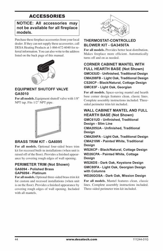
www.desatech.com 111244-01G44
aCCEssoRiEs
NOTICE: All accessories may not be available for all fireplace models.
Purchase these fireplace accessories from your local dealer. If they can not supply these accessories, call DESA Heating Products at 1-866-672-6040 for re-ferral information. You can also write to the address listed on the back page of this manual.
EQUIPMENT SHUTOFF VALVE GA5010For all models. Equipment shutoff valve with 1/8" NPT tap. Fits 1/2" NPT pipe.
BRASS TRIM KIT - GA6095For all models. Optional four-sided brass trim kit for recessed built-in installations (when unit is raised off of the floor). Provides a finished appear-ance by covering rough edges of wall opening.
PERIMETER TRIM (Not Shown)GA6094 - Polished Brass GAP6094 - PlatinumFor all models. Optional three-sided brass trim kit for custom and recessed installations (when unit is on the floor). Provides a finished appearance by covering rough edges of wall opening. Included with all mantels.
THERMOSTAT-CONTROLLED BLOWER KIT - GA3450TAFor all models. Provides better heat distribution. Makes fireplace more efficient. Automatically turns off and on as needed.
CORNER CABINET MANTEL WITH FULL HEARTH BASE (Not Shown)GMC63UD - Unfinished, Traditional DesignCMA208FB - Light Oak, Traditional DesignCS26CP - Black/Natural, Cottage DesignGMC83F - Light Oak, Georgian
For all models. Space-saving mantel and hearth base corner design features clean, classic lines. Complete assembly instructions included. Three-sided perimeter trim kit included.
WALL CABINET MANTEL AND FULL HEARTH BASE (Not Shown)GMC61UD - Unfinished, Traditional Design - Slim LineCMA205UA - Unfinished, Traditional DesignCMA204FA - Light Oak, Traditional DesignCMA210W - Painted White, Traditional DesignWS26CP - Black/Natural, Cottage DesignWD26CPA - Painted White, Cottage DesignWS26DS - Dark Oak, Keystone DesignGMC80FA - Light Oak, Georgian Design with ColumnsWD26GOSA - Dark Oak, Mission Design
For all models. Mantel features clean, classic lines. Complete assembly instructions included. Three-sided perimeter trim kit included.
www.desatech.com111244-01G 45
WALL-MOUNT THERMOSTAT SWITCH - GWMT1(Not Shown)For all remote-ready models. The desired com-fort setting can be selected on the wall thermostat and the fireplace will automatically cycle from pilot to the heat setting selected.
WALL-MOUNT ON/OFF SWITCH GWMS2(Not Shown)For all remote-ready models. Allows the fire-place to be turned on and off with a wall switch.
RECEIVER AND HAND-HELD THERMOSTAT REMOTE CONTROL KIT - HRC200 SERIESFor all remote-ready models. Allows the fire-place to be operated in a manually or thermostati-cally controlled mode. You can turn the fireplace on and off without ever leaving the comfort of your easy chair. A wall mount docking station is included.
aCCEssoRiEsContinued
RECEIVER AND HAND-HELD REMOTE CONTROL KIT - HRC100 SERIES For all remote-ready models. Allows the fire-place to be turned on and off by using a hand-held remote control. A wall mount docking station is included.
INFORMATION VIDEO - 108917-01For all models. A care and maintenance video is available by calling 1-866-672-6040. You may also email your request to [email protected].
FIRE CRACKLE - CF6-A(Not Shown)For all models. Creates the sound of a real burn-ing fire.

www.desatech.com 111244-01G46
NoTEs_____________________________________________________
_____________________________________________________
_____________________________________________________
_____________________________________________________
_____________________________________________________
_____________________________________________________
_____________________________________________________
_____________________________________________________
_____________________________________________________
_____________________________________________________
_____________________________________________________
_____________________________________________________
_____________________________________________________
_____________________________________________________
_____________________________________________________
_____________________________________________________
_____________________________________________________
_____________________________________________________
_____________________________________________________
_____________________________________________________
_____________________________________________________
_____________________________________________________
_____________________________________________________
_____________________________________________________
_____________________________________________________
_____________________________________________________
_____________________________________________________

www.desatech.com111244-01G 47
NoTEs_____________________________________________________
_____________________________________________________
_____________________________________________________
_____________________________________________________
_____________________________________________________
_____________________________________________________
_____________________________________________________
_____________________________________________________
_____________________________________________________
_____________________________________________________
_____________________________________________________
_____________________________________________________
_____________________________________________________
_____________________________________________________
_____________________________________________________
_____________________________________________________
_____________________________________________________
_____________________________________________________
_____________________________________________________
_____________________________________________________
_____________________________________________________
_____________________________________________________
_____________________________________________________
_____________________________________________________
_____________________________________________________
_____________________________________________________
_____________________________________________________

2701 Industrial DriveP.O. Box 90004Bowling Green, KY 42102-9004www.desatech.com
111244-01Rev. G01/06
NOT A UPC
111244 01