Unti 3 Ma c hni e co M p o sti oi n - BUNN Commercial · Unit Objectives Unti 3 Ma c hni e co M p o...
6
Unit Objectives UNIT 3 MACHINE COMPOSITION Given a realistic scenario in which the learner has access to the machine’s internal components the learner will under- stand the composition and functions of the machine. Given a realistic scenario requiring the learner to access the internal components of the machine the learner will be able to remove the top motor covers, side panels and front control panel. Given an operating machine the learner will be able to give a general explanation of how the machine operates. The learner will be able to identify the components and functions of the mechanical system. The learner will be able to identify the components and functions of the refrigeration system. The learner will be able to identify the component and function of the temperature sensing systems. The learner will be able to identify the components and functions of the remaining components not comprised in the identified systems.
-
Upload
nguyenkiet -
Category
Documents
-
view
212 -
download
0
Transcript of Unti 3 Ma c hni e co M p o sti oi n - BUNN Commercial · Unit Objectives Unti 3 Ma c hni e co M p o...

Unit Objectives
Unit 3 Machine coMposition
Given a realistic scenario in which the learner has access to the machine’s internal components the learner will under-stand the composition and functions of the machine.
Given a realistic scenario requiring the learner to access the internal components of the machine the learner will be able to remove the top motor covers, side panels and front control panel.
Given an operating machine the learner will be able to give a general explanation of how the machine operates.
The learner will be able to identify the components and functions of the mechanical system.
The learner will be able to identify the components and functions of the refrigeration system.
The learner will be able to identify the component and function of the temperature sensing systems.
The learner will be able to identify the components and functions of the remaining components not comprised intheidentifiedsystems.

Bunn-O-Matic Corporation21
Machine Composition
ExteriorOverview
Productoutletsandremovableparts
Hopper outlet(s)•Drip tray•Hopper(s)•Auger(s)•Faucet(s)•Hopper lid(s)•Airfilter•
RemovingtheEnclosure
The majority of the service work done to the ULTRA will require the service technician to access the inside of the machine. The ULTRA enclosure is comprised of two side panels, front control panel and two top motor covers to facilitate access to the refrigeration and electrical components.
Depending on the repair the technician may have to remove one or all of these panels. In order to work safely the power should be disconnected prior to removal of any body panel. Once the panels and drip tray are removed, the power can be reconnected in order to troubleshoot the machine.
FrontControlPanel
Removing the front control panel will give you access to the main control board, Tic board, switch membrane ribbon connection and hopper drip tray drain tubes.
How to Remove
The control panel is attached to the main housing by 1 hex slotted and 2 standard slotted screws.
Hopper Lid
Auger
Drip Tray
Faucet
Hopper
Air Filter(on back)

Ultra Training Manual22
Theleftandrightsidepanelwillneedtoberemovedfirsttogiveaccesstothesinglestandardslottedscrewoneachside. One ¼ inch hex slotted screw is located in the front support bracket located in front center behind the drip tray.
Thefrontcontrolpanelisnowreadyforfinalremovalbypullingdownwardandawayfromthemachine.Becautiousupon removing the panel because of the switch membrane connection.
Left Side Panel
Removing the left side panel will give you access to the refrigerant solenoids, hot gas sensor/thermistor and optional LAF water valve/ULTRA-1 only.
How to Remove
The left side panel is attached by 2, 1/4 inch hex slotted screws on the underside. Remove or loosen the screws and the panel is now ready for removal by pulling downward and out.
Hot Gas Sensor
Solenoids
Bunn-O-Matic Corporation23
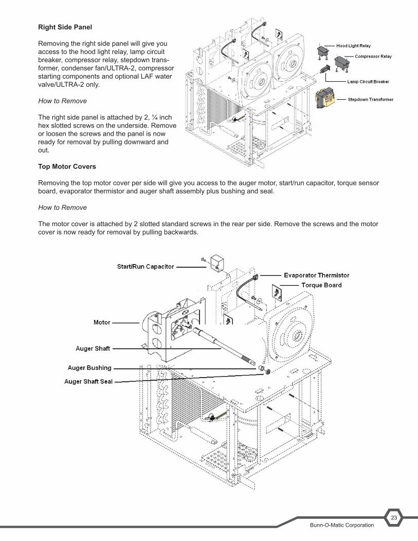
Right Side Panel
Removing the right side panel will give you access to the hood light relay, lamp circuit breaker, compressor relay, stepdown trans-former, condenser fan/ULTRA-2, compressor starting components and optional LAF water valve/ULTRA-2 only.
How to Remove
The right side panel is attached by 2, ¼ inch hex slotted screws on the underside. Remove or loosen the screws and the panel is now ready for removal by pulling downward and out.
TopMotorCovers
Removing the top motor cover per side will give you access to the auger motor, start/run capacitor, torque sensor board, evaporator thermistor and auger shaft assembly plus bushing and seal.
How to Remove
The motor cover is attached by 2 slotted standard screws in the rear per side. Remove the screws and the motor cover is now ready for removal by pulling backwards.

Ultra Training Manual24
MachineFunctionandOperations
TICBoard(TimeInaCan)
A Tic/Memory Clock is connected and located behind the main control board. The time and date is recorded after 100 hours of continuous power. The control board is checking the tic for clock information on a regular basis. If the communication is lost with the tic board, the CBA will keep trying to establish communication several times before it determines that the tic is no longer communicating or it is disconnected.
The result will be:Machine will display a message “Bad Tic Clock”•Machine will operate in default mode by turning the Augers On and Chill mode. This is done to keep product •
chilled. Denied access to programming by display message “Operating in Default Mode”•Turn the power switch on, machine will restore defaults automatically. You will see a countdown number along •
with restoring default message. MainControlBoard
The main control is the brain of the machine. The control board is the single component that contains all of the programming software, it interprets all the data it receives from the level probe (LAF & PAF), temperature sensors, switch inputs and torque monitor/sensor board. The input data received will command accordingly to turn on the out-puts to maintain a cold or ice product in the hopper.
Mechanical System
The mechanical system mixes the product, shaves the product from the cooling drum and pushes the product for-ward during dispensing mode. The product mixing and dispensing occurs as the auger motor rotates the auger. The auger will stop and run counterclockwise for 2 minutes on the hour or during a certain sequence that takes place with time and temperature of the product.
The thickness of the product is measured with a torque sensing system. This system utilizes two pins, one located on the auger shaft and one located on the auger motor shaft. The auger shaft is connected to the auger motor shaft via torsion springs, which allow the two pins to separate under torque. The distance between the pins is measured with a torque sensing board that emits a light beam every time the beam is broken by the pin on the auger motor. A signal is sent (voltage) to the main control board. The main control board processes this information and energizes/de ener-gizes the refrigeration system as needed to keep the product thickness consistent. The dispense system or faucets are manually operated by pulling down on the faucet handle until cup is full then release handle.
Refrigeration System
The cooling system for the Ultra is designed to make a frozen slush. This is accomplished through the use of a torque monitored refrigeration system. Upon initial startup of the machine, the compressor and fan will turn on after a delay. The amount of time for the delay is based on the cooling drum temperature. For instance, if the thermis-tors sense that both barrels, (one for Ultra-1), are above 50º F when the machine is powered up, the delay time is 1 minute. If any of the barrels are below 50º F, then the delay time is 6 minutes. Once the compressor and fan are operational the removal of heat from the product begins, cooling the product to programmed consistency. The thick-ness, (consistency), is set within the program menu and can range from 1 to 16. The thickness setting is 3 times the number, which is related to torque. The programmed setting is the operating parameter for the torque circuit, which monitors the product thickness. When the torque circuit determines the desired thickness is achieved the corresponding refrigerant valve is turned off and the compressor remains on for 30 seconds. If during this time the processor determines that cooling is still needed in the barrel(s), then the valve will open and the compressor continues to run. When the torque reading stays above the desired set point for over 30 seconds, then the microprocessor will shut off the output to the com-pressor relay coil, which turns off the compressor. The condenser fan runs for an additional minute after the compressor has shut down. Once the compressor has shut down it requires a 6 minute delay before it can restart.

Bunn-O-Matic Corporation25
SHAFTSHAFT
The system will determine if cooling is needed based on the torque reading. The actual setting that the processor uses is 3 times what the user has set in the menu. For instance: if the setting is at 10, then the system will turn the refrigerant valve off at 30. But also keep in mind that we have some hysteresis programmed into this setting, which is plus 1 and minus 2. This means that the valve will turn off above 31 and will not come back on until it drops below28.
Temperature Sensing System
The Ultra uses a thermistor to monitor the actual temperature of each cooling drum. Night and Chill modes maintain 35º F, instead of the torque sensing board (product thickness).
Torque Sensing
Thetorquespringswithintheaugershaftassemblywillflexdependingupontheamountoftorqueappliedtothetor-sion springs by the cooling of the product which creates ice crystals. The ice crystals size relates to the size of the gap created between the two pins (auger motor pin & auger shaft pin) .The “thickness” adjustment menu ranges from 1- 16 which sets the target gap between the pins.
Note: Product with high sugar content above 12 brix or alcohol will be a factor in longer freeze times. The product will need to go much lower than 32º F. before it may or may not form ice crystals.
Starts Freezing Stops Freezing 1/4” Gap Minimum 1/2” Gap Maximum
SETTHICKNESS? NO YES
LEFT 9 RIGHT 5