UNIVERSITY OF SOUTHERN QUEENSLAND · The Council of the University of Southern Queensland, ... 2.5...
156
UNIVERSITY OF SOUTHERN QUEENSLAND FACULTY OF ENGINEERING AND SURVEYING Review of Failure Mode, Effect and Criticality Analysis (FMECA) on major equipment of the crushing and screening plant at the BORAL Quarry at Ormeau, Queensland. A DISSERTATION SUBMITTED BY Mr Simon Jeffery In fulfilment of the requirements of Courses ENG4111 and 4112 Research Project Towards the degree of Bachelor of Engineering (Mechanical) Submitted: November 2009
Transcript of UNIVERSITY OF SOUTHERN QUEENSLAND · The Council of the University of Southern Queensland, ... 2.5...

UNIVERSITY OF SOUTHERN QUEENSLAND
FACULTY OF ENGINEERING AND SURVEYING
Review of Failure Mode, Effect and Criticality Analysis (FMECA) on major equipment of the crushing and screening plant at the
BORAL Quarry at Ormeau, Queensland.
A DISSERTATION SUBMITTED BY
Mr Simon Jeffery
In fulfilment of the requirements of
Courses ENG4111 and 4112 Research Project
Towards the degree of
Bachelor of Engineering (Mechanical)
Submitted: November 2009

0011221338 Page 2
ABSTRACT Project Title: Review of Failure Mode, Effect and Criticality Analysis(FMECA) on major
equipment of the crushing and screening plant at the BORAL Quarry at
Ormeau, Queensland
Author: Simon Jeffery
Supervisor: Chris Snook
This project was aimed to improve the reliability of the BORAL hard rock
crushing and screening plant at Ormeau. A literature review was documented,
highlighting the reasons for FMECA and the process involved in carrying the
procedure out. A review of BORAL downtime data was conducted, which
identified problem machines that were large contributors to downtime. A s study
of the plant identified the critical path of the plant and functional diagrams
showed dependencies between systems of individual machines. The FMECA
required ground rules for a true and consistent evaluation. The FMECA was
conducted, criticality values were given to failures and recommendations made
to prevent, predict, and fix failures more quickly. The recommendation were
expanded apon and developed into an item that can be used by staff to
implement the recommendations.

0011221338 Page 3
University of Southern Queensland
Faculty of Engineering and Surveying
ENG4111 Research Project Part 1 & ENG4112 Research Project Part 2
Limitations of Use
The Council of the University of Southern Queensland, its Faculty of Engineering and Surveying, and the staff of the University of Southern Queensland, do not accept any responsibility for the truth, accuracy or completeness of material contained within or associated with this dissertation. Persons using all or any part of this material do so at their own risk, and not at the risk of the Council of the University of Southern Queensland, its Faculty of Engineering and Surveying or the staff of the University of Southern Queensland. This dissertation reports an educational exercise and has no purpose or validity beyond this exercise. The sole purpose of the course "Project and Dissertation" is to contribute to the overall education within the student’s chosen degree programme. This document, the associated hardware, software, drawings, and other material set out in the associated appendices should not be used for any other purpose: if they are so used, it is entirely at the risk of the user.
Professor Frank Bullen Dean Faculty of Engineering and Surveying

0011221338 Page 4
Certification
I certify that the ideas, design and experimental work, results, analysis, and
conclusions set out in this dissertation are entirely my own efforts, except where
otherwise indicated and acknowledged.
I further certify that the work is original and has not been previously submitted
for assessment in any other course or institution, except where specifically
stated
SIMON PAUL JEFFERY
STUDENT NUMBER: 0011221338
SIGNATURE:
DATE: 26.10.09

0011221338 Page 5
ACKNOWLEDGEMENTS This research was carried out under the direct supervision of:
Chris Snook
Appreciation is also due to:
Neil Bellamy
Bob Pullman
Neil Cooper
Mike Cooper
Damien Kelly
Angela Jeffery
All onsite staff

0011221338 Page 6
TABLE OF CONTENTS Abstract
2
Disclaimer
3
Candidates Certification
4
Acknowledgments
5
List of Figures
9
List of Tables List of Appendices List of Abbreviations
10
12
12
Chapter 1 - PROJECT STATEMENT, AIMS AND OBJECTIVES 13
1.1 Project Statement 13 1.2 Project Aim 13 1.3 Specific Project Objectives 13
Chapter 2 - LITERATURE REVIEW
2.1 Project Methodology / Justification And Timeline 2.2 Risk Assessment 2.3 Background Information
2.3.1 History And Future Need For Reliability And Failure Analysis 2.3.2previous Research Of Reliability And Failure Analysis
14 14 14 15 15 15
2.4. Review of Procedure for Failure Mode Effects and Criticality Analysis 17 2.5 FMEA Process Described 18
2.5.1 Step 1 FMEA Process - Definition of the system 18 2.5.2 Step 2 FMEA Process - Development of reliability block diagrams 19 2.5.3 Step 3 FMEA Process - Establishment of ground rules 19 2.5.4 Step 4 FMEA Process - Failure Modes, causes and effects 19 2.5.5 Step 5 FMEA Process - Failure detection methods 20 2.5.6 Step 6 FMEA Process - Identification of alternative provisions 20 2.5.7 Step 7 FMEA Process - Report of FMEA process 20
2.6 Criticality Analysis 21 2.6.1 Procedure for Criticality Analysis – Severity Analysis 21 2.6.2 Procedure for Criticality Analysis – Probability of a Failure Mode 21 2.6.3 Procedure for Criticality Analysis – Criticality Evaluation 22 2.6.4 Determined Process for Criticality Evaluation of the crushing and screening plant at Boral Quarry, Ormeau.
2.7 Chapter Summary
22
23
Chapter 3 - REVIEW OF BORAL DOWNTIME DATA 3.1 Chapter Summary
24 27
0011221338 Page 7
Chapter 4 - REQUIREMENTS OF THE CRUSHING AND SCREENING PLANT
4.1 System Primary Functions 4.2 System Secondary Functions 4.3 System Uses 4.4 System Expected Performance 4.5 Explicit Conditions Which Constitute a Failure 4.6 Operational Uses 4.7 Definition of Functional Requirements 4.8 Definition of environmental Requirements 4.9 Regulatory Requirements 4.10 Chapter Summary
Chapter 5 - CRUSHING AND SCREENING PROCESS 5.1 Primary Crushing and Screening Section 5.2 Tertiary crushing and Screening Section 5.3 Chapter Summary
Chapter 6 - MACHINE DEFINITION 6.1 Pegson Jaw Crusher 6.2 Jaques 900mm Gyratory Cone Crusher 6.3 Omnicone Gyratory Crusher 6.4 Barmac Rotopactor VSI 6.5 Malco Vibrating Screens 6.6 Material Handling Conveyors 6.7 Material Handling transfer Points 6.8 Material handling Chutes 6.9 Aggregate Storage Bins 6.10 Surge Bin 6.11 Tipping Bin 6.12 Aggregate Bin Level Sensors 6.13 Aggregate Bin Gate Opening System 6.14 Aggregate Bin Truck 6.15 Dust Suppression System 6.16 Comp Air Rock Breaker 6.17 Atlas Copco Air Compressor 6.18 AS3000 6.19 Chapter Summary
Chapter 7 - DEVELOPMENT OF FUNCTIONAL DIAGRAMS 7.1 Functional Diagrams
7.1.1 Pegson Jaw Crusher 7.1.2 Jaques 900mm Gyratory Cone Crusher 7.1.3 Omnicone Gyratory Crusher 7.1.4 Barmac Rotopactor VSI 7.1.5 Malco Vibrating Screens 7.1.6 Material Handling Conveyors 7.1.7 Material Handling Transfer Points 7.1.8 Material Handling Chutes 7.1.9 Aggregate Storage Bin 7.1.10 Surge Bin 7.1.11 Aggregate Bin Level Sensors
28 28 29 29 29 31 31 32 32 32
35 35 39 44
45 46 49 54 57 60 63 64 65 65 66 66 66 67 67 68 68 69 69 69
70 70 71 73 76 79 81 82 85 86 87 88 88

0011221338 Page 8
7.1.12 Storage Bin Gate Opening System 7.1.13 Aggregate Bin Truck 7.1.14 Dust Suppression System 7.1.15 Comp Air Rock Breaker 7.1.16 Atlas Copco Air compressor
7.2 Chapter Summary
Chapter 8 - FMECA GROUND RULES 8.1 FMECA Structure 8.2 Infrastructure 8.3 Sub System 8.4 Failure Mode 8.5 Effect of Failure 8.6 Cause of Failure 8.7 Frequency of Occurrence 8.8 Detection 8.9 Severity 8.10 RPN 8.11 Recommendations 8.12 Chapter Summary
Chapter 9 - FMECA
Chapter 10 - RECOMMENDATIONS 10.1 Pegson Jaw Crusher 10.2 Jaques Gyratory Cone Crusher 10.3 Omnicone Gyratory Cone Crusher 10.4 Barmac Rotopactor VSI 10.5 Malco Vibrating Screens 10.6 Material Handling conveyors 10.7 Material Handling Transfer Points 10.8 Material Handling chutes 10.9 Aggregate Storage Bins and Surge Bin 10.10 Bin Level Sensors 10.11 Aggregate Bin Gate Opening System 10.12 Aggregate Bin truck 10.13 Dust Suppression System 10.14 Comp Air Rock Breaker 10.15 Structural Framing 10.16 Atlas Copco Air Compressor 10.17 Electrics
Chapter 11 – CONCLUSION Chapter 12 – LIST OF REFERENCES Chapter 13 - APPENDICES
89 81 92 93 94 95
96 96 96 97 98 98 98 98 99
100100100100
101
110110114118123125128131133135137138140141143146145148
149
151
153
0011221338 Page 9
LIST OF FIGURES Figure 1 Components of FMECA 17 Figure 2 Criticality Evaluation 22 Figure 3 BORAL Machine Downtime Contributors 25 Figure 4 BORAL Downtime Chart 26 Figure 5 Production Rate Chart 27 Figure 6 Primary and Secondary Process Diagram 37 Figure 7 Tertiary Process Diagram 41 Figure 8 Jaw Crusher Cross sectional Assemblies 48 Figure 9 Gyratory Cone Crusher Cross section 49 Figure 10 CSS reference output rock size 50 Figure 11 Jaques Cone Crusher oil System 51 Figure 12 Jaques Cone Crusher Cross Section 52 Figure 13 Omnicone Gyratory Cone Crusher Cross Section 54 Figure 14 Barmac VSI Cross Section 59 Figure 15 Fluid Coupling Cross Section 61 Figure 16 Vibrating Screen General Assembly 61 Figure 17 Vibrating Screen Operational. 61 Figure 18 Vibrating Screen Cross Section 62 Figure 19 Conveyor General Arrangement 64 Figure 20 Interaction types used in functional diagrams 71 Figure 21 Example System Dependency 71 Figure 22 Functional diagram for Jaw Crusher 72 Figure 23 Functional diagram for Jaques Gyratory Cone Crusher, 74 Figure 24 Functional diagram for Omnicone Gyratory Cone Crusher 77 Figure 25 Functional diagram for Barmac VSI 80 Figure 26 Functional diagram for Malco vibrating screens 81 Figure 27 Functional diagram for Material Handling Conveyors 83 Figure 28 Functional diagram for Material Handling Transfer points 85 Figure 29 Functional diagram for Material Handling Chutes 86 Figure 30 Functional diagram for Aggregate Storage Bins 87 Figure 31 Functional diagram for Surge Bin 88 Figure 32 Functional diagram for Aggregate Bin Level Sensor 89 Figure 33 Functional diagram for Aggregate Bin Gate Opening system 90 Figure 34 Functional diagram for Bin Truck system 91 Figure 35 Functional diagram for Dust Suppression 92 Figure 36 Functional diagram for Rock Breaker system 93 Figure 37 Functional diagram for Air Compressor 94

0011221338 Page 10
LIST OF TABLES Table 0 Project Milestones 14 Table 1 Existing approved hours of operation 32 Table 2 Noise limits for the Ormeau Quarry 33 Table 3 Air quality limits for the Ormeau Quarry 34 Table 4 Primary and Secondary System definition 37 Table 5 Tertiary System definition 41 Table 6 Jaw Crusher Cross parts sheet 48 Table 7 Jaques Cone Crusher Parts List 53 Table 8 Omnicone Gyratory Cone Crusher parts sheet 55 Table 9 Barmac VSI Part 59 Table 10 Vibrating Screen Parts 62 Table 11 Jaw Crusher Sub Assembly Details 73 Table 12 Jaques Cone Crusher Sub Assemblies Details 75 Table 13 Omnicone Sub Assemblies Detail 78 Table 14 Barmac Sub Assemblies Detail 80 Table 15 Vibrating Screens Sub Assemblies Detail 82 Table 16 Material Handling Conveyor Sub Assemblies Detail 84 Table 17 Material Handling Transfer point Sub Assemblies Detail 85 Table 18 Material Handling Chutes Sub Assemblies Detail 86 Table 19 Aggregate Storage Bin Sub Assemblies Detail 87 Table 20 Surge Bin Sub Assemblies Detail 88 Table 21 Aggregate Bin Level Indicator System Sub Assemblies Detail 89 Table 22 Aggregate Bin Gate Opening System Sub Assemblies Detail 90 Table 23 Bin Truck Sub Assemblies Detail 91 Table 24 Dust Suppression Sub Assemblies Detail 92 Table 25 Rock Breaker Sub Assemblies Detail 93 Table 26 Air Compressor Sub Assemblies Detail 94 Table 27 First three columns of the FMECA 97 Table 28 Frequency value itemisation 99 Table 29 Severity value itemisation 99 Table 30 Severity value itemisation 100Table 31 Critical spares list for jaw crusher 111Table 32 Routine inspection program for jaw crusher 111Table 33 Maintenance supervision program for jaw crusher 112Table 34 Operator supervision program for jaw crusher 112Table 35 Installation list for jaw crusher 113Table 36 Critical spares list for Jaques cone crusher 113
0011221338 Page 11
Table 37 Routine inspection list for Jaques cone crusher 115Table 38 Routine monitoring list for Jaques cone crusher 116Table 39 Routine testing list for Jaques cone crusher 117Table 40 Installation list for Jaques cone crusher 117Table 41 Operator supervision list for Jaques cone crusher 117Table 42 Routine maintenance list for Jaques cone crusher 118Table 43 Critical spares list for Omnicone crusher 119Table 44 Routine inspection list for Omnicone crusher 120Table 45 Routine monitoring list for Omnicone crusher 120Table 46 Routine testing list for Omnicone crusher 121Table 47 Installation list for Omnicone crusher 121Table 48 Operator supervision list for Omnicone crusher 122Table 49 Routine maintenance list for Omnicone crusher 123Table 50 Critical spares list for Barmac VSI 124Table 51 Routine inspection list for Barmac VSI 124Table 52 Routine maintenance list for Barmac VSI 124Table 53 Installation list for Barmac VSI 125Table 54 Operator supervision list for Barmac VSI 125Table 55 Critical spares list for Malco vibrating screen 126Table 56 Routine inspection list for Malco vibrating screen 127Table 57 Routine maintenance list for Malco vibrating screen 127Table 58 Operator supervision list for Malco vibrating screen 127Table 59 Maintenance supervision list for Malco vibrating screen 127Table 60 Routine testing list for Malco vibrating screen 128Table 61 Installation list for Malco vibrating screen ( 128Table 62 Critical spares list for Material handling conveyors 129Table 63 Routine inspection list for Material handling conveyors 130Table 64 Routine maintenance list for Material handling conveyors 131Table 65 Installation list for Material handling conveyors 131Table 66 Critical spares list for Material handling transfer points 132Table 67 Routine inspection list for Material handling transfer points 132Table 68 Maintenance supervision list for Material handling transfer points 132Table 69 Routine maintenance list for Material handling transfer points 132Table 70 Installation list for Material handling transfer points 133Table 71 Critical spares list for Material handling chutes 133Table 72 Routine maintenance list for Material handling chutes 134Table 73 Installation list for Material handling chutes 135Table 74 Maintenance supervision list for storage bins and surge bin 135Table 75 Routine inspection list for aggregate storage bins and surge bin 135

0011221338 Page 12
Table 76 Routine maintenance list for aggregate storage bins and surge bin 135Table 77 Installation list for aggregate storage bins and surge bin 136Table 78 Critical spares list for aggregate bin level sensors 137Table 79 Critical spares list for aggregate bin gate opening system 138Table 80 Routine inspection list for aggregate bin gate opening system 139Table 81 Routine maintenance list for aggregate bin gate opening system 139Table 82 Critical spares list for aggregate bin truck system 140Table 83 Critical spares list for dust suppression system 141Table 84 Routine inspection list for dust suppression system 141Table 85 Routine maintenance list for dust suppression system 142Table 86 Critical spares list for Comp Air rock breaker 143Table 87 Routine inspection list for Comp Air rock breaker 143Table 88 Routine maintenance list for Comp Air rock breaker 144Table 89 Installation list for Comp Air rock breaker 144Table 90 Routine inspection list for Atlas Copco air compressor 145Table 91 Routine inspection list for structural framing 146Table 92 Routine inspection list for structural framing 147Table 93 Critical spares list for electrics 148Table 94 Routine maintenance list for electrics 148 LIST OF APPENDICES Appendix A Project Specification 155Appendix B Project Programme 156Appendix C Project Risk Register 157Appendix D Daily crushing Data Sheet 156 LIST OF ABBREVIATIONS CSS Close Side Setting QRS Quarry Reporting System IEMS Integrated Environmental Management System GCCC Gold Coast City Council IQA Institute of Quarries Australia

0011221338 Page 13
1. PROJECT STATEMENT, AIMS AND OBJECTIVES 1.1 PROJECT STATEMENT Conduct a Failure Mode and Effect and Criticality Analysis (FMECA) on major
equipment of the crushing and screening plant at the Boral Quarry at Ormeau,
Queensland, and develop an appropriate maintenance strategy and any
recommendations to improve the plant. 1.2 PROJECT AIM The aim of this project is to reduce the unplanned downtime as a result of
failures to the crushing and screening plant at the Boral Quarry at Ormeau,
Queensland. To achieve this aim, a Failure Mode and Effect and Criticality
Analysis (FMECA) will be undertaken. 1.3 Specific Project Objectives The objectives of this project are to:
• Confirm that FMECA is the most appropriate analysis to undertake to
ensure the reliability and reduced failure of the crushing and screening
plant at the Boral Quarry at Ormeau, Queensland.
• Determine what is required to undertake a FMECA.
• Acquire the needed information.
• Conduct the FMECA
• Develop a maintenance plan that can be used effectively by employees
to maintain the plant, with particular attention to the critical path of the
plant.
• Provide any recommendations to improve the running of the plant. The process has the potential to improve the reliability and reduce failure of the
crushing and screening plant at numerous Quarry in South East Queensland.
Following the assessment of the project, consideration may be given to
recommending FMECA be undertaken for all the plants across South East
Queensland.

0011221338 Page 14
2. LITERATURE REVIEW 2.1 PROJECT METHODOLOGY / JUSTIFICATION AND TIMELINE
The delivery method of this project has been broken into activities and
coordinated in the Gantt chart included as appendix 01. The key milestones
have been listed below in table 0 with the intention of completing each activity
by the date noted.
In this report the application of the FMECA process and Boral Quarry Data will
be reviewed to determine the need for the project. It is anticipated that the
Quarry data will confirm unplanned downtime due the system failures. The
review of reliability and failure analysis will be undertaken to determine if
FMECA is the most suitable process to undertake in order to reduce the system
failures and therefore increase reliability, the quarry plant performance and
overall profit.
1 Submit project statement for review 11/03/09
2 Commence research for project appreciation 12/03/09
4 Complete and submit project appreciation 25/05/09
5 Commence FMECA process on Boral plant 14/08/09
6 Determine recommendations 11/09/09
7 Submit 95% complete dissertation 23/10/09
8 Submit final dissertation 30/10/09
Table 0: Project Milestones
2.2 RISK ASSESSMENT The University of Southern Queensland, Project Reference Book (2009) notes
the importance of risk assessment to engineering projects due to legal and
financial implications. A detailed risk assessment and register for the project
included as appendix 2. The identified project risks have been assessed
against:
• Risk category; • Risk description and details; • Likelihood; • Consequence;
0011221338 Page 15
• Risk factor; • Risk treatment; and • Responsibility
The risk assessment identified several ‘high’ risk items associated with the
project completion. This assessment has ensured that appropriate mitigation
strategies have been applied to all risks in order to reduce both the likelihood
and consequence.
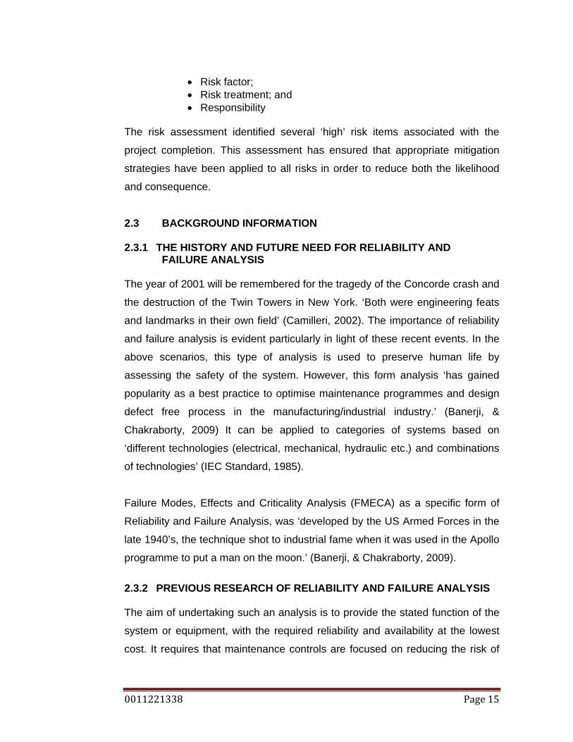
2.3 BACKGROUND INFORMATION 2.3.1 THE HISTORY AND FUTURE NEED FOR RELIABILITY AND
FAILURE ANALYSIS The year of 2001 will be remembered for the tragedy of the Concorde crash and
the destruction of the Twin Towers in New York. ‘Both were engineering feats
and landmarks in their own field’ (Camilleri, 2002). The importance of reliability
and failure analysis is evident particularly in light of these recent events. In the
above scenarios, this type of analysis is used to preserve human life by
assessing the safety of the system. However, this form analysis ‘has gained
popularity as a best practice to optimise maintenance programmes and design
defect free process in the manufacturing/industrial industry.’ (Banerji, &
Chakraborty, 2009) It can be applied to categories of systems based on
‘different technologies (electrical, mechanical, hydraulic etc.) and combinations
of technologies’ (IEC Standard, 1985).
Failure Modes, Effects and Criticality Analysis (FMECA) as a specific form of
Reliability and Failure Analysis, was ‘developed by the US Armed Forces in the
late 1940’s, the technique shot to industrial fame when it was used in the Apollo
programme to put a man on the moon.’ (Banerji, & Chakraborty, 2009).
2.3.2 PREVIOUS RESEARCH OF RELIABILITY AND FAILURE ANALYSIS The aim of undertaking such an analysis is to provide the stated function of the
system or equipment, with the required reliability and availability at the lowest
cost. It requires that maintenance controls are focused on reducing the risk of

0011221338 Page 16
failure and supported by sound technical and economical justification. As with
any philosophy, there are many processes that can lead to the final goal. For
reliability engineering the varying processes are listed below:
• Failure Rate Prediction; • Fault Tree Analysis; • Event Tree Analysis; • Reliability Block Diagram Analysis; • Markov Analysis; • Petri Net Analysis; • Stress-Strength Analysis; and • Failure Mode and Effect (Criticality) Analysis
Previous Studies have been undertaken to determine the most effective
reliability and failure analysis for plant and equipment used at Boral Quarry’s. A
dissertation undertaken by Robbie Cox (2008) at the Queensland University of
Technology reviewed the above process and assessed both the benefits and
limitations and determined the following:
Techniques such as Markov, Petri Net and Stress-Strength analysis involve difficult computational operations that can become unmanageable and impossible without the use of a software tool.
Event and fault tree techniques while useful in forming cut sets for future analysis require the production of a new tree for each initiating event or failure mode respectively. Large number of analysis techniques can become problematic when planning and are sometimes difficult to manage. Stress-Strength, Failure Rate Prediction and Markov analysis require in some instances large sources of machine and environmental information to produce meaningful results, therefore the implementation of such techniques is applicable to situations that have historical information and operational technical data. FMECA, Event Tree analysis, Fault Tree analysis and Reliability Block Diagram analysis are useful in logically representing systems, system failure paths, component and sub-assembly interaction and components and sub-assemblies that are more susceptible to failure and can cause propagated damage.
The dissertation undertaken by Cox (2008) determined that the most
appropriate method of reliability and failure analysis of plant and equipment
used at Boral Quarry’s was a combination of FMECA, Event tree analysis, Fault
tree analysis and reliability block diagrams.

0011221338 Page 17
Following the review of the International Electrotechnical Commission (IEC)
Standard for Analysis techniques for system reliability – Procedure for failure
mode and effects analysis (1985) it has been determined that during the pre-
design and design stages FMECA proves to be essential but not sufficient, it
should be applied in combination with Event Tree analysis, Fault Tree analysis
and Reliability Block Diagram analysis. As the crushing and screening plant at
the Boral Quarry at Ormeau, Queensland is a well established plant and is not
in the pre design stage it is determined that FMECA (of which function block
diagram is a part of) is the most appropriate process to undertake to ensure the
reliability of the plant. 2.4 REVIEW OF PROCEDURE FOR FAILURE MODE EFFECTS AND
CRITICALITY ANALYSIS Banerji, & Chakraborty (2009) described the standard components of a FMECA
as shown in figure 1.
Figure 1: (Banerji, & Chakraborty 2009)
The IEC developed a standard (1985) to document the procedure to carryout
Failure Mode Effect Analysis (FMEA) and Failure Mode Effect Criticality
Analysis (FMECA). The standard aligns with figure 1, however it provides
further detail on each of the components. The steps required to carry out FMEA
as per the IEC standard (1985) are listed below.
1. Definition of the system; 2. Development of functional block diagrams; 3. Establishment of ground rules; 4. Failure Modes, causes and effects;

0011221338 Page 18
5. Failure detection methods; 6. Identification of alternative provisions; 7. Report of FMEA process.
The IEC standard (1985) addresses all the general considerations presented for
FMEA which apply to FMECA as one is an extension the following steps are
only required when undertaking FMECA (IEC Standard 1985). Note: the
reporting of the process is carried out at the end of FMECA.
8. Determination of event criticality;
2.5 FMEA PROCESS (AS A PART OF FMECA PROCESS) DESCRIBED
2.5.1 STEP 1 FMEA PROCESS - DEFINITION OF THE SYSTEM AND ITS
REQUIREMENTS
The IEC standard (1985) notes that the definition of the system should consists
of:
• A definition of both primary and secondary functions; • Its use; • Expected performance; • System constraints; and • Explicit conditions which constitutes a failure; and • Functional narratives of the system’s operation for each mode
and its duration. The definition of the system should also include information on its functional and
environmental requirements. The functional requirements note both acceptable
functional performance and the characteristics considered unacceptable
performance. The environment (temperature, humidity, radiation, vibration and
pressure) where the system will function also needs to be defined.

0011221338 Page 19
2.5.2 STEP 2 FMEA PROCESS - DEVELOPMENT OF FUNCTIONAL BLOCK DIAGRAMS
Functional block diagrams are developed to show functional elements of the
system, they provide technical understanding, show any series, superfluous
relationships and functional failures.
2.5.3 STEP 3 FMEA PROCESS - ESTABLISHMENT OF GROUND RULES Ground rules are established to determine levels of analysis and rely upon the
system results desired. The highest system level is determined as the specified
output where as the lowest system level is specified mostly for a newly
designed system or one with little reliability history.
2.5.4 STEP 4 FMEA PROCESS - FAILURE MODES, CAUSES AND
EFFECTS Failure modes can be categorised into a set of general failure modes. These
being (IEC standard 1985):
• Premature operation; • Failure to operate at a prescribed time; • Failure to cease operation at a prescribed time; and • Failure during operation
As any system consists of many components, determining the critical system
and ensuring its performance will result in the successful operation of the
overall system.
The cause of a failure to a system can be an independent failure of one
component. It is imperative that potential failure causes for all components of
the system be identified. The IEC standard (1985) notes the cause of a failure
mode is determined to:
• Predict the probability of occurrence; • Uncover secondary effects; and • Devise recommended corrective actions.
Common causes of failures are listed below. Note: the list is note extensive.
• Structure failure; • Physical binding or jamming;

0011221338 Page 20
• Vibration; • Fails to open or close, stop or start; and • Internal or external leakages;
The effect is a direct result of a failure mode. ‘Failure mode effects focus on the
specific system element in the functional diagram being analysed which is
affected by the failure under consideration.’ (IEC Standard 1985).
2.5.5 STEP 5 FMEA PROCESS - FAILURE DETECTION METHODS The failure detection methods need to be described when undertaking the
analysis. It is imperative that when a single component of the system is being
assessed for failure, if any other component will be affected by initial failure, it
should be recorded as this will assist in failure detection of subsequent
components.
2.5.6 STEP 6 FMEA PROCESS - IDENTIFICATION OF ALTERNATIVE
PROVISIONS
Once the failure mode is detected, the significance of the failure needs to be
recorded along with any relevant or proposed design features and other
provision that may assist in reducing/eliminating the failure mode. The IEC
Standard (1985) notes some of the provisions:
• Redundant items that allow continued operation if one or more elements fail;
• Alternative means of operation; • Monitoring or alarm devices; and • Any other means permitting effective operation or limiting
damage. 2.5.7 STEP 7 FMEA PROCESS - REPORT OF ANALYSIS The IEC standard (1985) recommends that the report of the FMEA should
record
• Description of the methodology; • The assumptions and ground rules; • Recommendations for designers, maintenance staff, planners
and users; and

0011221338 Page 21
• Failures that result in serious effects.
2.6 CRITICALITY ANALYSIS Criticality analysis is undertaken in order ‘to quantify the severity of a failure
effect and to estimate the probability of occurrence of the relevant failure mode.’
(IEC Standard 1985) The process for determining severity and probability are
described in items 2.6.1 and 2.6.2 respectively. Once the severity and
probability of the failure mode have been determined its total criticality to the
system is evaluated, this process is described in item 2.6.3.
2.6.1 PROCEDURE FOR CRITICALITY ANALYSIS –SEVERITY ANALYSIS
To determine the criticality of a failure mode, it needs to be assessed in relation
to the overall performance of the system requirements, objectives and
constraints. The IEC Standard (1985) suggests that severity is classified by the
following categories:
• death or injury to operation personnel or to the public;
• damage to external equipment or the equipment itself;
• economic loss due to lack of output or function; and
• failure to complete a task due to inability of equipment to perform its
major function.
2.6.2 PROCEDURE FOR CRITICALITY ANALYSIS – PROBABILITY OF A
FAILURE MODE Once the procedure for FMEA is complete, using the data directly from the
sources sited, a quantitative assessment, specifically, analytically derived
estimates, can be undertaken to determine the probability of occurrence for
each postulated failure mode. (IEC FMEA 1985)
Rethinking engineering: risk and reliability analysis, a paper written to promote
engineers using analytical tools when undertaken studies of reliability,
references a numbering system used to reference probability. Assigning a
baseline figure ‘targeting probability for normal cases, as what society

0011221338 Page 22
nowadays seems to accept or consider unavoidable’ (Camilleri, 2002) to enable
probability to be assessed either below or above the baseline figure.
2.6.3 PROCEDURE FOR CRITICALITY ANALYSIS – CRITICALITY
EVALUATION Criticality Analysis and its evaluation is crucial in determining failure mode
priorities and the clear delineation between what is acceptable and what is not
acceptable in the performance of any given system. Prioritising failure modes
and determining acceptable versus not acceptable is what governs the decision
making process and corrective actions. Without appropriate corrective actions
the risk and result of a failure mode could be greatly increased.
The IEC standard (1985) has developed a matrix, shown in figure 02, to assist
in criticality evaluation. The level of Criticality is recorded from one (1) – four (4)
vertically and the probability of failure is recorded horizontally as either very low,
low, medium or high. The further result is noted from the origin diagonally, the
greater the criticality and the more urgent need for corrective action (IEC
Standard 1985).
Figure 2: Criticality Evaluation (IEC Standard 1985).
Banerji and Chakraborty (2009) recommend allocating a numerical figure to
severity, ‘x’ and a numerical figure to frequency indicated as ‘y’. The criticality of
the failure mode can then be assessed as ‘xy’. This is indicated in figure 2.
0011221338 Page 23
2.7 CHAPTER SUMMARY Following the review of the literature above on criticality analysis, being severity,
probability and the overall evaluation, the criticality of assessment of the
crushing and screening plant at the Boral Quarry at Ormeau for this project will
be undertaken by:
• Determining the frequency of the failure mode against a numerical
figure allocated to ‘target probability for one year for normal cases,
as what society nowadays seems to accept or consider unavoidable
anyway’ as recommended in the paper Rethinking engineering.
• Similarly, a figure for severity will be assigned to determine a
baseline for which all failure modes can be assessed against.
• A third value will also be used in the calculation of the criticality
analysis, and that being detection. This value will refer to the detect
ability of a failure.
• The overall criticality of the failure mode will be assessed as a
multiplication of severity ‘x’ and frequency ‘y’ and detection ‘z’ as
recommended in the paper Banerji and Chakraborty (2009), and the
authors preference.

0011221338 Page 24
3. REVIEW OF BORAL DOWNTIME DATA The aim of this project is to reduce the failure of the crushing and screening
plant at the Boral Quarry at Ormeau. Failure in the plant results in downtime of
the system, which is logged in the Quarry reporting system database (QRS). A
downtime event is registered whenever the belt weigher is reading less than 50
tonnes per hour on the main conveyor in the system. This information is logged
to a data taker, and then is transferred to the QRS. The plant operator must
then specify the cause of the downtime in the ‘Daily Crushing Data Sheet’, see
appendix D. The reporting system tracks all plant downtime across Boral South
East Queensland Quarries, recording details such as:
• Location • Duration of the downtime; and • Asset downtime • Cause of the downtime (planned versus unplanned)
Planned downtime for crushing and screening plant is necessary to maintain the
system. The optimum level of maintenance can be determined as a ratio of
operational hours versus maintenance hours. As ‘Quarries produce material
through a continuous process the failure of one component can often result in
the entire production line being halted’. (Cox 2008) Ultimately this will affect
production and profit. Therefore, it is unplanned maintenance that will benefit
from undertaking an FMECA and developing appropriate maintenance
strategies.
The information recorded in the QRS can be analysed to determine common
failures, that is, unplanned downtime. The downtime duration and frequency
can be used in the FMECA to determine criticality. This log of information will be
invaluable when undertaking the FMECA process.
0011221338 Page 25
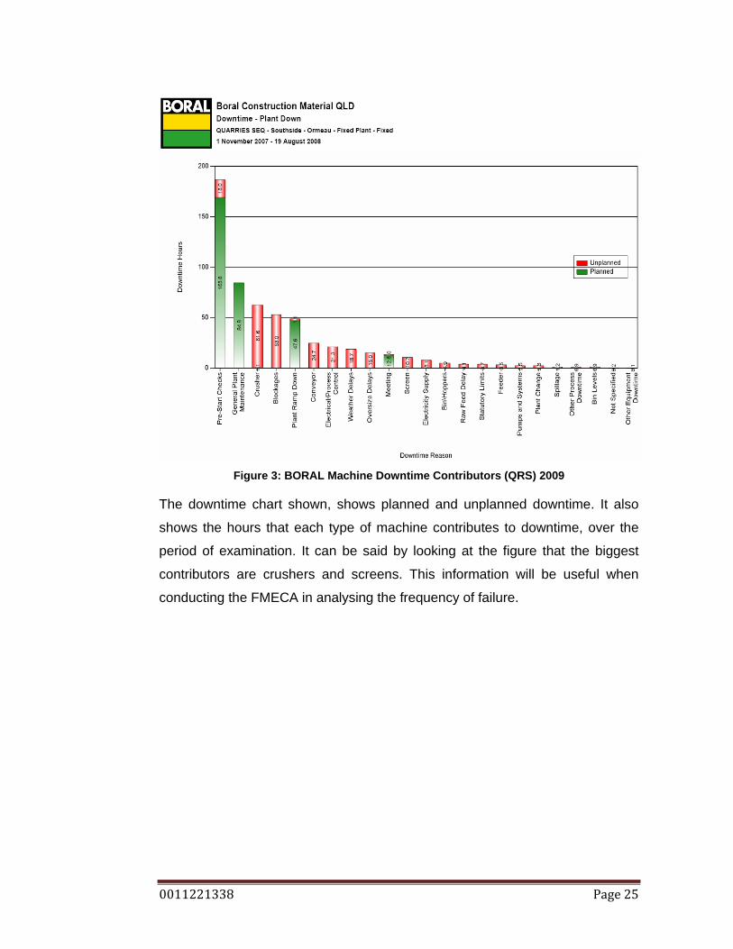
Figure 3: BORAL Machine Downtime Contributors (QRS) 2009
The downtime chart shown, shows planned and unplanned downtime. It also
shows the hours that each type of machine contributes to downtime, over the
period of examination. It can be said by looking at the figure that the biggest
contributors are crushers and screens. This information will be useful when
conducting the FMECA in analysing the frequency of failure.

0011221338 Page 26
Figure 4: BORAL Downtime Chart (QRS) 2009
The Overall Equipment Effectiveness (OEE), is a measure for quantifying the
performance of a plant. It is a calculation involving a plants, yield percentage,
efficiency percentage and availability percentage. The figure for analysis from
this graph is the availability, which it the percentage downtime of the total
available crushing hours. It can be seen that the availability for this analysis
period ranges from approximately 70% to 90%.
0011221338 Page 27
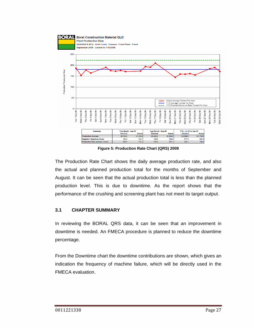
Figure 5: Production Rate Chart (QRS) 2009
The Production Rate Chart shows the daily average production rate, and also
the actual and planned production total for the months of September and
August. It can be seen that the actual production total is less than the planned
production level. This is due to downtime. As the report shows that the
performance of the crushing and screening plant has not meet its target output.
3.1 CHAPTER SUMMARY
In reviewing the BORAL QRS data, it can be seen that an improvement in
downtime is needed. An FMECA procedure is planned to reduce the downtime
percentage.
From the Downtime chart the downtime contributions are shown, which gives an
indication the frequency of machine failure, which will be directly used in the
FMECA evaluation.
0011221338 Page 28
4. REQUIREMENTS OF THE CRUSHING AND SCREENING PLANT
4.1 SYSTEM PRIMARY FUNCTIONS
The primary function of the Ormeau Crushing and Screening plant is to supply
South East Queensland with a high quality screened aggregate to be utilized in
concrete and asphalt for construction projects.
It is a primary function of the Ormeau plant to operate in a safe manner and
allow operator access on and around the plant during both operation and
downtime. Safe access to all components of plant is required to ensure the
operation and maintenance can be carried without causing any injury to
personnel.
The plant at Ormeau is required to have minimal effect of the environment. The
crushing and screening process can produce moderate levels of dust, vibration
and noise. It is a primary function of the plant to minimize these environmental
effects. (N Bellamy 2009, pers. comm., 01 June.)
4.2 SYSTEM SECONDARY FUNCTIONS
A secondary function of the Ormeau Crushing and Screening plant is to operate
with a high level of reliability. Due to local council regulations, the plant can
operate within the hours 7am to 6pm, Monday to Friday. It is a requirement that
the plant operates consistently within these hours and for the entire hours. A
reliability measure is monitored using the QRS (Quarry Reporting System) as a
reliability percentage and a unscheduled downtime percentage. Reliability is
major secondary function of the Ormeau plant. (N Bellamy 2009, pers. comm.,
01 June.)
0011221338 Page 29
4.3 SYSTEM USES
The Ormeau Crushing and Screening Plant is used to crush raw material of
size, 700-1000mm in diameter, and screen to produce: 35mm, 16mm, 14mm,
10mm, 7mm, and 5mm aggregates and course dust and fine dust. This process
occurs by passing crushed material through screens with varying aperture holes
in them. For example, a 10mm aggregate can be produced by screening
material through a 12mm screen and across the top of an 8mm screen.
The Ormeau plant is required to produce a high quality aggregate as this
aggregate is a major constituent in products such concrete and asphalt used in
public construction projects. Registered technicians test samples of the
aggregate to ensure it meets the required specifications, this testing is
undertaken to protect the public using the product. A possible reason for an
aggregate sample not meeting specifications regarding the crushing and
screening plant is contamination, meaning aggregates of different sizes in a
specified aggregate size sample. (Hoffman, 2008)
4.4 SYSTEM EXPECTED PERFORMANCE The Ormeau Crushing and Screening plant was designed to operate with
maximum capacity:
• For 11 hours a day, 5 days a week (55 hours of processing);
• Process approximately 180-200 tonnes per hour of raw material;
• Have a minimal effect of the environment;
• Be safe to operate and maintain; and
• Produce a quality screened aggregate;
4.5 EXPLICIT CONDITIONS WHICH CONSTITUTE A FAILURE
There are many explicit conditions that constitute a failure. A failure or
downtime event is recorded any time there is less than 50 tonnes per hour on

0011221338 Page 30
conveyor 1, the main conveyor. A belt weigher is permanently reading the
weight on conveyor 1. This information is sent to a data logger. The information
from the data logger is downloaded to a computer program which itemizes each
time the belt weigher read less than 50 tonnes per hour and is called a
downtime event. Each downtime event is assigned a cause. The causes for
downtime events are grouped into such groups as: (Daily Crushing Data Sheet,
BORAL, 2004)
1. General maintenance 2. Crusher 3. Conveyor 4. Screens 5. Clean up 6. Bin/Hopper 7. Feeders 8. Plant change 9. Electrical/Process control 10. Pumps and systems 11. Metal detector trip (MDT) 12. Electricity supply 13. Other equipment downtime 14. Meetings 15. Meal breaks 16. Early finishes 17. Pre – start checks 18. Shot firing 19. Staff shortage 20. OH&S issue 21. Raw feed delay 22. Blockage 23. Oversized delays 24. Spillage 25. Weather delays 26. Statutory limits 27. Other processing downtime 28. Bin levels 29. Production ramp down 30. Nil surge
The downtime event is classified into one of these groups of explicit conditions
Even though the QRS only registers a downtime event when the belt weight
drops below 50 tonnes per hour, this is a 75% loss in production, and would not

0011221338 Page 31
be efficient to run. Therefore it has been decided that when the production rate
drops below 150 tonnes per hour, there is a failure somewhere, and constitutes
a failure. (N Bellamy 2009, pers. comm., 01 June.)
4.6 OPERATIONAL USE The Ormeau Crushing and Screening plant can operate at different production
configurations. Depending on the aggregate demand, production configurations
must change. The most common configurations include:
1. 16mm minus 2. 14mm minus 3. 10mm minus
A configuration of 16mm minus means 16mm and smaller size aggregates will
be produced, while anything larger than 16mm will be returned to the crusher
for re-crush and a reduction in size. A production configuration of 16mm minus
will have a high production rate and the production rate will decrease as the
size of the production configuration decreases.
4.7 DEFINITION OF FUNCTIONAL REQUIREMENTS
The definitions of acceptable performance of the system are the same as the
expected performance which include:
• For 11 hours a day, 5 days a week (55 hours of processing); • Process no less than 180 tonnes per hour of raw material; • Have a minimal effect of the environment; • Be safe to operate and maintain; and • Produce a quality screened aggregate;
The definition of unacceptable performance of the system as include:
• During an eleven hour day of crushing to have an accumulative
downtime total of 105.6 minutes would be completely unacceptable. This would calculate to give the planned 84% machine availability given by the monthly Quarry Performance Summary (QRS, 2009).
• 1760.4 tonnes of raw material needs to be processed a day, this is inline with the planned 35207.5 tonnes given by the monthly

0011221338 Page 32
Quarry Performance Summary. A total less than 1760 tonnes would be also unacceptable performance, (QRS, 2009).
• Any injury resulting from any system on the Crushing and Screening plant would be unacceptable performance.
• Have an effect on the environment that is greater than allowable. • Produce aggregates that have contamination of any sort.
4.8 DEFINITION OF ENVIRONMENTAL REQUIRMENTS The definition of the environment that the crushing plant is expected to operated
within would include:
• Temperatures that range from approximately 8 degrees Celsius in
the winter to 35 degrees Celsius in the summer. • An environment that can be high levels of dust concentration • The system is operated in the open environment, therefore
humidity, aging, corrosion, are common. • A small level of vibration.
4.9 REGULATORY REQUIREMENTS
The Ormeau Quarry site is located in the Gold Coast City Council, the council
determines and enforces strict operating hours on the quarry (Holley, 2009).
The hours are as follows:
Activity Monday to Friday Saturday Sunday
Extraction 7am – 6pm Not permitted Not permitted Crushing & Screening 7am – 6pm Not permitted Not permitted Blasting 10am – 2pm Not permitted Not permitted Maintenance 7am – 6pm 8am – 12pm Not permitted Load and Haul to plant 7am – 6pm 8am – 12pm Not permitted Sales and Dispatch 7am – 6pm 8am – 12pm Not permitted
Table 1: Existing approved hours of operation
Operating hours that pertain to the crushing plant are the: Crushing and
Screening hours, Maintenance hours, and the Load and Haul to the plant hours.
The Ormeau quarry site, as all Australian Quarry site are, is regulated by such acts as:
• Mining and Quarrying Safety and Health Regulations 2001. • Explosives Act.

0011221338 Page 33
• IEMS (Boral Integrated Environmental Management System, December 2001), which is issued to the Environmental Protection Agency, EPA, and states how each site is going to meet the requirements of the EPA.
With in the IEMS document the limits for: Water contaminate release, Noise,
Blasting, and Air are stated. Again the sections that relate to the Crushing and
Screening Plant are Noise and air quality. The limits for noise are as follows
(Rigby 2001):
Noise level at a noise sensitive place measured as LAmax,AdjT:
• 7am-10pm: background noise level plus 5dB(A) and;
• 10pm-7am: background noise level plus 3dB(A)
Noise level at a commercial place measured as LAmax,AdjT:
• 7am-10pm: background noise level plus 10dB(A) and;
• 10pm-7am: background noise level plus 8dB(A)
Table 2: Noise limits for the Ormeau Quarry (IEMS, 2001) Noise is required to be monitored only after a complaint has been made (IEMS, 2001) The limits for air quality are as follows: Ambient particulate matter 120 mg/m^2/day 24 hour average concentration of particulate matter
150ug/m^3/24 hour average
Table 3: Air quality limits for the Ormeau Quarry (IEMS, 2001)
Air quality is required to be constantly monitored (IEMS, 2001). This
requirement is fulfilled with the site having 3 air quality monitors permanently
placed around the site.
4.10 CHAPTER SUMMARY The main purpose of the crushing and screening plant is to process raw
material, of a size of approximately 700mm – 900mm, into screened usable
aggregates and to do it safely and in an environmentally responsible fashion.

0011221338 Page 34
The plant must do this between the hours of 7am to 6pm on weekdays only,
and be maintained between the hours 7am – 6pm on weekdays and 8am –
12pm on Saturday. During the hours of operation, the plant needs to process at
least 35207.5 tonnes in a month. Any time that the plant is processing less than
50 tonnes an hour, a downtime event is registered and classified as 1 of 30
explicit conditions, which is logged to the QRS system.
The plant also needs to abide by environmental regulations, such as air quality
levels: 120 mg/m^2/day and 150ug/m^3/24 hour average, and noise limits of:
7am-10pm: background noise level plus 5dB(A) and; 10pm-7am: background
noise level plus 3dB(A) in a noise sensitive place and in a commercial place:
7am-10pm: background noise level plus 10dB(A) and;10pm-7am: background
noise level plus 8dB(A)
0011221338 Page 35
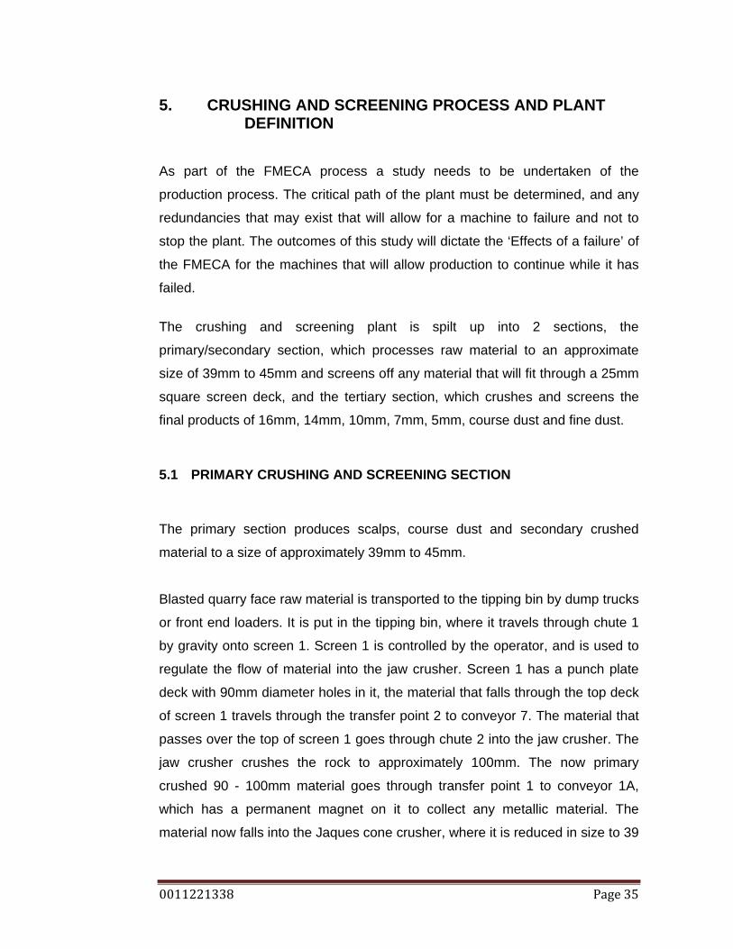
5. CRUSHING AND SCREENING PROCESS AND PLANT DEFINITION
As part of the FMECA process a study needs to be undertaken of the
production process. The critical path of the plant must be determined, and any
redundancies that may exist that will allow for a machine to failure and not to
stop the plant. The outcomes of this study will dictate the ‘Effects of a failure’ of
the FMECA for the machines that will allow production to continue while it has
failed.
The crushing and screening plant is spilt up into 2 sections, the
primary/secondary section, which processes raw material to an approximate
size of 39mm to 45mm and screens off any material that will fit through a 25mm
square screen deck, and the tertiary section, which crushes and screens the
final products of 16mm, 14mm, 10mm, 7mm, 5mm, course dust and fine dust.
5.1 PRIMARY CRUSHING AND SCREENING SECTION
The primary section produces scalps, course dust and secondary crushed
material to a size of approximately 39mm to 45mm.
Blasted quarry face raw material is transported to the tipping bin by dump trucks
or front end loaders. It is put in the tipping bin, where it travels through chute 1
by gravity onto screen 1. Screen 1 is controlled by the operator, and is used to
regulate the flow of material into the jaw crusher. Screen 1 has a punch plate
deck with 90mm diameter holes in it, the material that falls through the top deck
of screen 1 travels through the transfer point 2 to conveyor 7. The material that
passes over the top of screen 1 goes through chute 2 into the jaw crusher. The
jaw crusher crushes the rock to approximately 100mm. The now primary
crushed 90 - 100mm material goes through transfer point 1 to conveyor 1A,
which has a permanent magnet on it to collect any metallic material. The
material now falls into the Jaques cone crusher, where it is reduced in size to 39
0011221338 Page 36
– 45mm. The now secondary crushed rock flows through transfer point 3 to
conveyor 1 and through transfer point 5 to screen 3. Screen 3 is a 2 deck
screen, the top deck has 25mm aperture screens, any material that flows over
this deck travels through transfer point 7 to conveyor 10 and to the surge bin.
Material that passes through the top deck of screen 3 and across the bottom
deck, which has 5mm aperture screens on it, flows through chute 3 to the
Barmac. Material that goes through the bottom deck goes to Bin 13 as a final
product of course dust. The material that was passed onto conveyor 7, moves
through the transfer point 4 to conveyor 8, through transfer point 6 to screen 4.
Screen 4 which has a single deck of 25mm aperture, material that passes over
the top of the screen deck goes to transfer point 7 to conveyor 10 and to the
surge bin also. Material that falls through the top deck of screen 4 moves
through chute 5 to bin 16 as a final product called scalps. The bins are empties
through bin gates, which are actuated by pneumatic cylinders.

0011221338 Page 37
SCREEN 1
PRIMARYJAW
CRUSHER
JAQUESCONE
CRUSHER
SCREEN 4
SCREEN 3
TRANSFERPOINT 3
BIN 16
TRANSFERPOINT 6
BIN 15
CHUTE 3
CHUTE 4
BARMAC
TRANSFER POINT 5
CONVEYOR 1A
CONVEYOR 1
CHUTE 2
TRANSFERPOINT 1
TRANSFERPOINT 2
CONVEYOR 8
SURGEBIN
CONVEYOR 7
TRANSFERPOINT 4
TRANSFERPOINT 7
CHUTE 5
CONVEYOR 10
WATER SPRAYS
MAGNET
TIPPING BIN
CHUTE 1
RAW MATERIAL
AIRCOMPRESSOR
AIRRECEIVER
BIN GATEACTUATORAIR SUPPLY
BIN GATE BIN GATE
MAGNET
Figure 6: Primary and Secondary Process Diagram
Item Component Description
Raw material Face rock transported to the plant
Tipping bin Machines tip loads of raw material into the tipping bin, where it waits to be feed into the plant.
Chute 1 Delivers material from the tipping bin to screen 1 Chute 2 Delivers material from screen 1 to the jaw crusher
Chute 3 Delivers material from the bottom deck of screen 3 to the Barmac VSI.

0011221338 Page 38
Chute 4 Delivers material that falls through the bottom deck of screen 3 to bin 13
Chute 5 Delivers material that falls through the top deck of screen 4 to bin 16
Transfer point 1 Transfers primary crusher rock from the output of the jaw crusher to conveyor 1A
Transfer point 2 Transfers material that falls through the top deck, of screen 1 to conveyor 7(Approximately 90mm minus),
Transfer point 3 Transfers secondary crushed material from the output of the Jaques Cone Crusher to conveyor 1
Transfer point 4 Transfers material from conveyor 7 to conveyor 8
Transfer point 5 Transfers material from conveyor 1 to the input of screen 3
Transfer point 6 Transfers material from conveyor 8 to the input of screen 4
Transfer point 7 Transfers material that is screened across the top deck of screen 3 and 4 (Approximately 40mm – 25mm) to conveyor 10
Conveyor 1A Handles material from transfer point 1 to the Jaques cone crusher
Conveyor 1 Handles material from transfer point 3 to transfer point 5
Conveyor 7 Handles material from transfer point 2 to transfer point 4
Conveyor 8 Handles material from transfer point 4 to transfer point 6
Conveyor 10 Handles material from transfer point 7 to the surge bin
Jaques Cone Crusher
Crushes primary crushed material of size 100-90mm into secondary crushed material of size 45-39mm.
Jaw crusher Crushes 750mm to 90mm raw, quarry face material
Barmac VSI Vertical Shaft Impactor (VSI), shapes material of size 25-5mm
Screen 1 Single deck screen, the deck is an impact plate with 90mm holes in it.
Screen 3 Double deck screen: top deck uses 25mm square, wire, screens; bottom deck has 5mm square screens.
Screen 4 Single deck screen, the deck uses 25mm square, wire screens.
Magnet Permanent magnet placed over the top of the conveyor to remove material contamination
Surge bin 30 tonne surge bin, provides lag time between the primary and tertiary. The surge bin feeds the tertiary section 45-25mm material.
Bin 16 Bin 16 is feed 25mm minus material from screen 4, called Scalps
0011221338 Page 39
Bin 15 Bin 15 is feed 5mm minus material from screen 3, called course dust.
Air system
The air system consists of a: air compressor, air receiver, air lines, pneumatic actuators and electronically controlled directional control valves operated by a wireless activation system.
Table 4: Primary and Secondary System definition
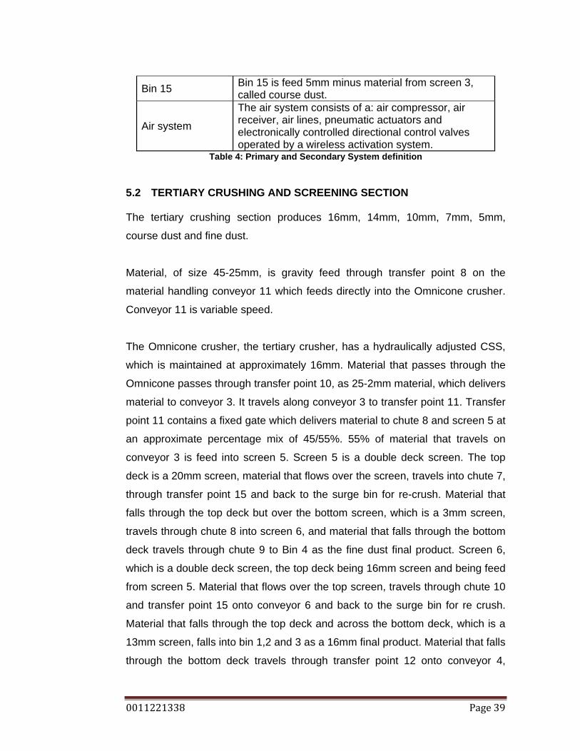
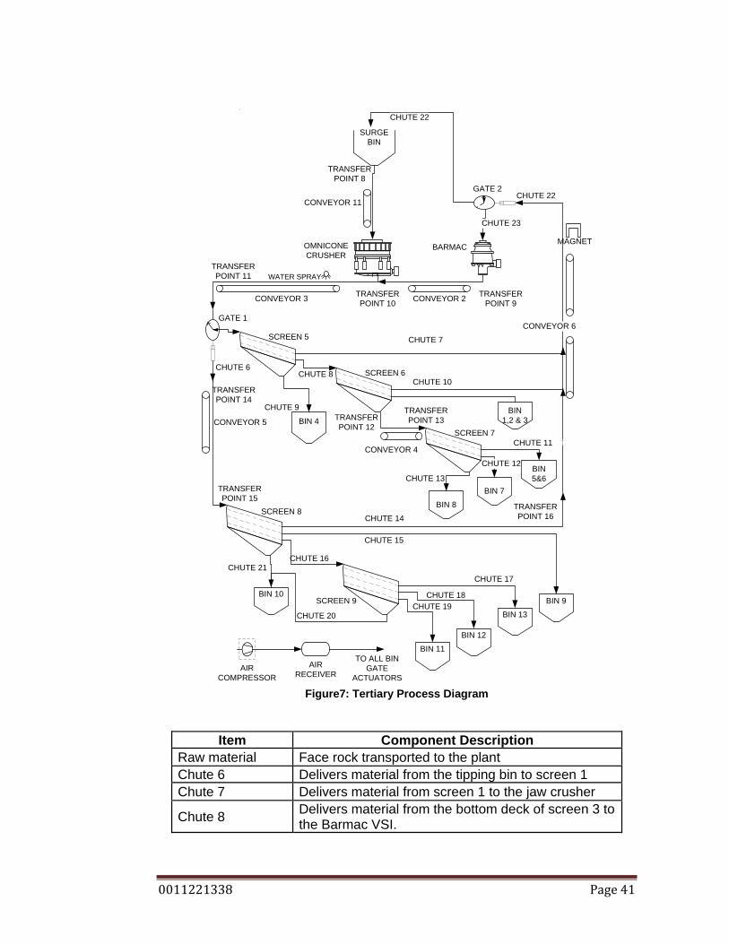
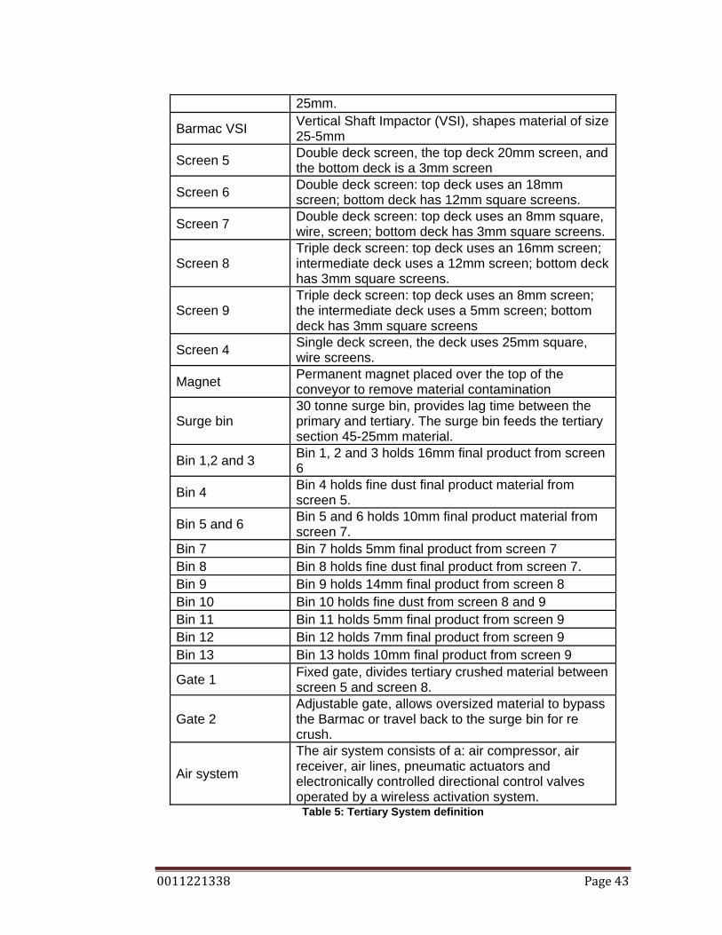
5.2 TERTIARY CRUSHING AND SCREENING SECTION The tertiary crushing section produces 16mm, 14mm, 10mm, 7mm, 5mm,
course dust and fine dust.
Material, of size 45-25mm, is gravity feed through transfer point 8 on the
material handling conveyor 11 which feeds directly into the Omnicone crusher.
Conveyor 11 is variable speed.
The Omnicone crusher, the tertiary crusher, has a hydraulically adjusted CSS,
which is maintained at approximately 16mm. Material that passes through the
Omnicone passes through transfer point 10, as 25-2mm material, which delivers
material to conveyor 3. It travels along conveyor 3 to transfer point 11. Transfer
point 11 contains a fixed gate which delivers material to chute 8 and screen 5 at
an approximate percentage mix of 45/55%. 55% of material that travels on
conveyor 3 is feed into screen 5. Screen 5 is a double deck screen. The top
deck is a 20mm screen, material that flows over the screen, travels into chute 7,
through transfer point 15 and back to the surge bin for re-crush. Material that
falls through the top deck but over the bottom screen, which is a 3mm screen,
travels through chute 8 into screen 6, and material that falls through the bottom
deck travels through chute 9 to Bin 4 as the fine dust final product. Screen 6,
which is a double deck screen, the top deck being 16mm screen and being feed
from screen 5. Material that flows over the top screen, travels through chute 10
and transfer point 15 onto conveyor 6 and back to the surge bin for re crush.
Material that falls through the top deck and across the bottom deck, which is a
13mm screen, falls into bin 1,2 and 3 as a 16mm final product. Material that falls
through the bottom deck travels through transfer point 12 onto conveyor 4,

0011221338 Page 40
through transfer point 13 and into screen 7. Screen 7 in a double deck screen,
the top deck being an 8mm screen, material that flows across the top of the
screen travels through chute 11 into bin 5 and 6 as a 10mm final product.
Material that falls through the top deck and flows across the bottom deck, which
is 3mm screen, travels through chute 12 into bin 7 as a 5mm final product.
Material that falls through the bottom deck falls through chute 13, into bin 8 as a
course dust final product.
The tertiary crushed material that is diverted through the fixed gate from
conveyor, travels through chute 6, into transfer point 13 and onto conveyor 5.
The material travels though transfer point 14 and into screen 8. Screen 8 is a
triple deck screen, material that flows across the top of the screen is returned to
the surge bin for re crush though: chute 14, transfer point 15, conveyor 6 and
chute 22. Material that falls through the top deck, but across the middle deck,
travels through chute 15 to bin 9 as a 14mm final product. Material that fell
though the middle deck, but across the bottom deck travels through chute 16 to
screen 9. Material that fell through the bottom deck moves through chute 21 to
bin 10 as fine dust final product. Screen 9 is also a triple deck screen. Material
that travels across the top screen moves through chute 17 to bin 13 as a 10mm
final product. Material that fell through the top deck and moves across the
middle deck is transported through chute 18 to bin 12 as a 7mm final product.
Material that fell through the middle deck but moves across the bottom deck,
travels through chute 19 to bin 11 as a 5mm final product. Material that falls
through the bottom deck, travels through chute 20 to bin 10 as a fine dust final
product. Material travelling back to the surge bin for re crush can be diverted
into the Barmac through the adjustable gate. The adjustment of the gate which
varies the amount of material going into the Barmac, depends on the operating
current draw.
0011221338 Page 41
BARMAC OMNICONECRUSHER
SCREEN 5
SCREEN 8
SCREEN 9
SURGEBIN
SCREEN 6
BIN 4SCREEN 7
TRANSFER POINT 10
CHUTE 14
GATE 2
MAGNET
BIN1,2 & 3
CHUTE 10
BIN 9
TRANSFERPOINT 16
BIN 10
BIN 13
BIN 12
BIN 11
CONVEYOR 2CONVEYOR 3
CHUTE 13
CHUTE 23
CONVEYOR 11
CONVEYOR 5
CHUTE 6
TRANSFERPOINT 8
GATE 1
CHUTE 9
TRANSFERPOINT 9
CHUTE 8
TRANSFERPOINT 12
CONVEYOR 4
CHUTE 22
CHUTE 7
TRANSFERPOINT 11
CHUTE 16
CHUTE 17
CHUTE 15
CONVEYOR 6
BIN5&6
BIN 7
BIN 8
`CHUTE 11
CHUTE 12
CHUTE 18CHUTE 19
CHUTE 20
CHUTE 21
CHUTE 22
TRANSFERPOINT 13
TRANSFERPOINT 14
TRANSFERPOINT 15
WATER SPRAY
AIRCOMPRESSOR
AIRRECEIVER
TO ALL BINGATE
ACTUATORS Figure7: Tertiary Process Diagram
Item Component Description Raw material Face rock transported to the plant Chute 6 Delivers material from the tipping bin to screen 1 Chute 7 Delivers material from screen 1 to the jaw crusher
Chute 8 Delivers material from the bottom deck of screen 3 to the Barmac VSI.

0011221338 Page 42
Chute 9 Delivers material that falls through the bottom deck of screen 3 to bin 13
Chute 10 Delivers material that falls through the top deck of screen 4 to bin 16
Chute 11 Delivers material from screen 7 to bin 5 and 6 Chute 12 Delivers material from screen 7 to bin 7 Chute 13 Delivers material from screen 7 to bin 8 Chute 14 Delivers material from screen 6 to transfer point 15 Chute 15 Delivers material from screen 9 to bin 9 Chute 16 Delivers material from screen 8 to screen 9 Chute 17 Delivers material from screen 9 to bin 13 Chute 18 Delivers material from screen 9 to bin 12 Chute 19 Delivers material from screen 9 to bin 11 Chute 20 Delivers material from screen 9 to bin 10 Chute 21 Delivers material from screen 8 to bin 10 Chute 22 Delivers material from conveyor 6 to the surge bin.
Chute 23 Delivers diverted material from conveyor 6 to the Barmac.
Transfer point 8 Transfers material from the surge bin to conveyor 11
Transfer point 9 Transfers material from the output of the Barmac to conveyor 2
Transfer point 10 Transfers material from conveyor 2 to conveyor 3 and also material from the output of the Omnicone crusher to conveyor 3.
Transfer point 11 Transfers material from conveyor 3 to fixed gate 1
Transfer point 12 Transfers material that falls through the bottom deck of screen 6 to conveyor 4
Transfer point 13 Transfers material from conveyor 4 to screen 7 Transfer point 14 Transfers material from chute 6 to conveyor 5 Transfer point 15 Transfers material from conveyor 5 to screen 8
Transfer point 16 Transfers material from chute 14, chute 10 and chute 7 to conveyor 6.
Conveyor 2 Handles material from transfer point 9 to the Jaques cone crusher
Conveyor 3 Handles material from transfer point 10 to transfer point 11
Conveyor 4 Handles material from transfer point 12 to transfer point 13
Conveyor 5 Handles material from transfer point 13 to transfer point 14
Conveyor 6 Handles material from transfer point 15 to the surge bin
Conveyor 11 Handles material from transfer point 8 to transfer to the Omnicone crusher
Omnicone Crusher
Crushes secondary crushed material of size 30-45mm into tertiary crushed material of size 18-
0011221338 Page 43
25mm.
Barmac VSI Vertical Shaft Impactor (VSI), shapes material of size 25-5mm
Screen 5 Double deck screen, the top deck 20mm screen, and the bottom deck is a 3mm screen
Screen 6 Double deck screen: top deck uses an 18mm screen; bottom deck has 12mm square screens.
Screen 7 Double deck screen: top deck uses an 8mm square, wire, screen; bottom deck has 3mm square screens.
Screen 8 Triple deck screen: top deck uses an 16mm screen; intermediate deck uses a 12mm screen; bottom deck has 3mm square screens.
Screen 9 Triple deck screen: top deck uses an 8mm screen; the intermediate deck uses a 5mm screen; bottom deck has 3mm square screens
Screen 4 Single deck screen, the deck uses 25mm square, wire screens.
Magnet Permanent magnet placed over the top of the conveyor to remove material contamination
Surge bin 30 tonne surge bin, provides lag time between the primary and tertiary. The surge bin feeds the tertiary section 45-25mm material.
Bin 1,2 and 3 Bin 1, 2 and 3 holds 16mm final product from screen 6
Bin 4 Bin 4 holds fine dust final product material from screen 5.
Bin 5 and 6 Bin 5 and 6 holds 10mm final product material from screen 7.
Bin 7 Bin 7 holds 5mm final product from screen 7 Bin 8 Bin 8 holds fine dust final product from screen 7. Bin 9 Bin 9 holds 14mm final product from screen 8 Bin 10 Bin 10 holds fine dust from screen 8 and 9 Bin 11 Bin 11 holds 5mm final product from screen 9 Bin 12 Bin 12 holds 7mm final product from screen 9 Bin 13 Bin 13 holds 10mm final product from screen 9
Gate 1 Fixed gate, divides tertiary crushed material between screen 5 and screen 8.
Gate 2 Adjustable gate, allows oversized material to bypass the Barmac or travel back to the surge bin for re crush.
Air system
The air system consists of a: air compressor, air receiver, air lines, pneumatic actuators and electronically controlled directional control valves operated by a wireless activation system. Table 5: Tertiary System definition

0011221338 Page 44
5.3 CHAPTER SUMMARY
The production process has been defined and after researching the plant, it is
clear that all machines are on the critical path of the production process. There
are no redundancies available. When evaluating the ‘Effect of failure’ in the
FMECA process, as the effect of some failures will cause the plant to stop, the
effect is the opposite to the aim of reducing unscheduled downtime, and
therefore will be evaluated quite high.

0011221338 Page 45
6. MACHINE DEFINITION From the process diagrams shown in Chapter 5, it can be seen that the
following machines make up the crushing and screening plant at Ormeau.
• 1 Pegson jaw crusher, 1100mm x 850mm, as the primary crusher
• 1 900mm Jaques gyratory cone crusher in a secondary configuration
• 1 Nordberg Omnicone gyratory crusher, tertiary configuration
• 1 Barmac Rotopactor Vertical Shaft Impact crusher (VSI) as the
quaternary crusher
• 8 Malco 2.4m x 1.2m vibrating screens
• 11 material handling conveyors of different sizes
• Material handling transfer points
• Material handling chutes.
• 16 aggregate storage bins
• Surge bin
• Aggregate bin level sensors.
• Aggregate bin gate opening system
• Aggregate bin truck
• Dust suppression system
• Comp Air hydraulic rock breaker.
• 1 Atlas Copco air compressor.
All of the above machines make up the crushing and screening plant and all lie
on the critical path of the production process, meaning that if one of the above
machines fails, then all production is lost.
As a step in the FMECA process, it is necessary to define how each machine
operates and the systems that are involved in allowing the function to occur.
0011221338 Page 46
6.1 PEGSON JAW CRUSHER
The Pegson 1100mm x 850mm jaw crusher is the primary crusher in the
process of the Ormeau Crushing and Screening plant. It is referred to as the
primary crusher because of its position in the system; it is the first crush in the
process. Raw material ranging in size from 90mm to 700mm in diameter is feed
into the crusher. The crusher size classification of 1100mm x 850mm is the
rectangular feed opening at the top of the crusher.
Raw material which has been screened over a punch plate with 90mm holes in
it, meaning anything that will not fit through a hole of a 90mm diameter, is feed
into the jaw crusher. The jaw reduces this material by placing it in compression
between a fixed jaw face and a moving jaw face also referred to as the swing
jaw face. The fixed jaw, which uses a wear liner, is aligned with the swing jaw in
a V configuration with the swing jaw which also uses a wear liner. The fixed jaw
face is the stationary breaking surface, while the swing jaw exerts the breaking
force to the rock. It does this by forcing it against the fixed jaw face. The
distance between the fixed jaw face and the moving jaw face at its closest is
called the Close Side Setting (CSS); this is relative to the size of rock being
outputted, as a rock will remain in the crushing V section until it is small enough
to pass through onto the discharge conveyor.
The swing jaw gets its movement profile from the eccentricity of the eccentric
shaft. This particular jaw has a 37mm eccentricity. The top of the swing jaw face
is connected to the eccentric shaft, through the pitman frame, while the bottom
of the swing jaw is held by the toggle plate assembly and the toggle rod
assembly which are both hinged to allow movement in the vertical direction and
also horizontal direction. The jaw crusher motion is a continuous cycle.
The toggle plate assembly allows the bottom of the pitman to move up and
down with the motion of the eccentric shaft as well as provide a protection to the
jaw. The toggle plate has a specified strength in compression, if something is
feed into the jaw crusher that has compression strength higher than that of the

0011221338 Page 47
toggle plate, and is bigger than the CSS, then it will bend and allow the foreign
object through the jaw opening without causing major damage to the jaw
crusher. Details can be viewed at <http://www.aggdesigns.com/Jaw-Crusher-
info.htm>
The tension rod assembly includes a rod and spring. It serves the purpose of a
tensioning the lower end of the swing jaw to the toggle seats, which are the
areas where the toggle plate sits.
Drive to the Jaw crusher is provided through multiple drive V belts driven by an
110KW electric motor. Rotational energy is supplied into the crusher by large
flywheels mounted on both sides of the eccentric shaft. The flywheels are not
mounted eccentrically; they are mounted on machined centred surfaces.
Lubrication is required daily for the jaw crusher eccentric shaft bearings, this
daily greasing is undertaken by the operator at approximately mid day, as
through experience it has been found that greasing has been more effective if
greased when the bearings are at operating temperature and running at
operating speed. (N Bellamy 2009, pers. comm., 01 June.)
The feed material is abrasive and so throughout the life of fixed jaw wear liner
and the swing jaw wear liner the CSS is adjusted to maintain a constant output
size of rock. This is done by adding shims, into the required position which is
behind the toggle block and against the structural frame. This moves the bottom
of the swing jaw toward the fixed jaw. Wear liners because of the nip points
being at the bottom of the crusher, most of the wear occurs there and so the jaw
wear liners can be rotated to give the operator maximum life from the wear
liners.
0011221338 Page 48
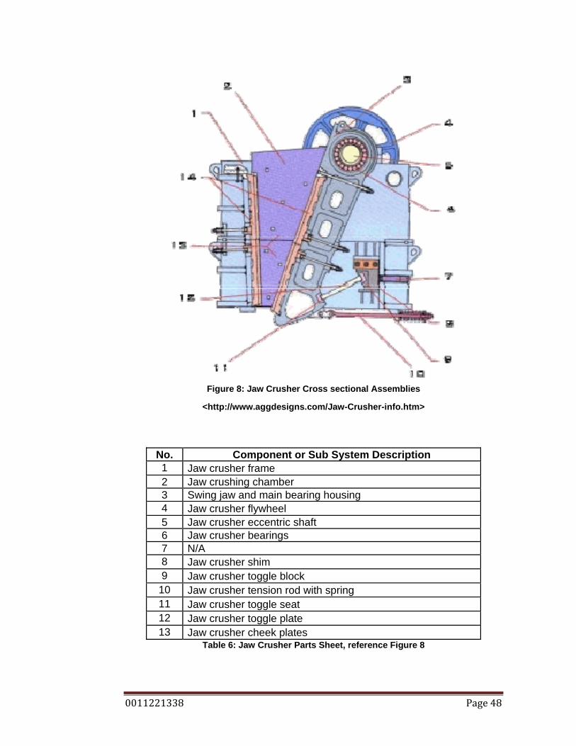
Figure 8: Jaw Crusher Cross sectional Assemblies
<http://www.aggdesigns.com/Jaw-Crusher-info.htm>
No. Component or Sub System Description 1 Jaw crusher frame 2 Jaw crushing chamber 3 Swing jaw and main bearing housing 4 Jaw crusher flywheel 5 Jaw crusher eccentric shaft 6 Jaw crusher bearings 7 N/A 8 Jaw crusher shim 9 Jaw crusher toggle block 10 Jaw crusher tension rod with spring 11 Jaw crusher toggle seat 12 Jaw crusher toggle plate 13 Jaw crusher cheek plates
Table 6: Jaw Crusher Parts Sheet, reference Figure 8
0011221338 Page 49
CRUSHER PROTECTION SYSTEM There is no protection system for the jaw crusher. It is started on demand and
shut down on demand.
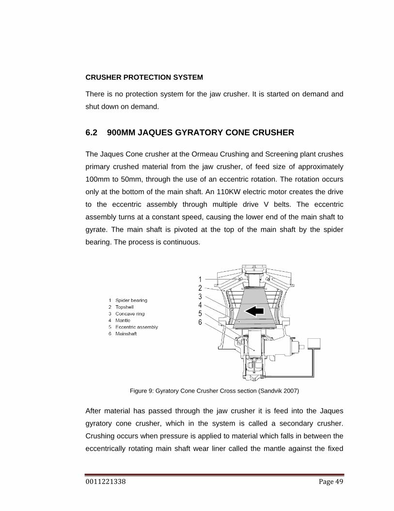
6.2 900MM JAQUES GYRATORY CONE CRUSHER
The Jaques Cone crusher at the Ormeau Crushing and Screening plant crushes
primary crushed material from the jaw crusher, of feed size of approximately
100mm to 50mm, through the use of an eccentric rotation. The rotation occurs
only at the bottom of the main shaft. An 110KW electric motor creates the drive
to the eccentric assembly through multiple drive V belts. The eccentric
assembly turns at a constant speed, causing the lower end of the main shaft to
gyrate. The main shaft is pivoted at the top of the main shaft by the spider
bearing. The process is continuous.
Figure 9: Gyratory Cone Crusher Cross section (Sandvik 2007)
After material has passed through the jaw crusher it is feed into the Jaques
gyratory cone crusher, which in the system is called a secondary crusher.
Crushing occurs when pressure is applied to material which falls in between the
eccentrically rotating main shaft wear liner called the mantle against the fixed

0011221338 Page 50
wear liners called the concave ring and concaves. Due to the eccentric rotation
there is a close side between the mantle wear liner and the concave wear liner,
and also an open side. Therefore feed material falls into the crushing chamber
and is crushed at the nip points, close side, as the mantle eccentrically rotates
around the concave. Some material may fall through the cycle without being
crushed on the open side. Material that has passed through the crusher on the
open side will be crushed on other cycles. After material, which is now called
secondary crushed, falls onto a discharge conveyor and travels to the next
stage of the process. (Cox 2008)
The close side distance of the crushing chamber is called the Close Side
Setting (CSS). The CSS is the distance from the mantle to the concave at the
point where nipping occurs. The larger the CSS, the larger the output rock will
be. The CSS can be adjusted and is accomplished by raising or lowering the
main shaft assembly. By raising the main shaft assembly, the CSS would
decrease. The open side measurement, on the opposite side of the mantle is
called the open side setting (OSS). The OSS is equal to the eccentricity plus the
CSS. The adjustment is achieved mechanically. The top of the main shaft
assembly is threaded, and so by way of turning the suspension nut the height of
the main shaft assembly and subsequently the CSS is adjusted.
Figure 10: CSS reference output rock size (Sandvik 2007)

0011221338 Page 51
As a secondary crusher, it uses a superior mantle and concave, this refers to
the shape of these two components. The shape allows for a larger input size of
material, while still outputting a well reduced size of rock. This is referred to as
the Percentage Reduction. Therefore the percentage reduction of the 900mm
Jaques Gyratory Cone Crusher is higher than the tertiary crushing
configuration. (N Bellamy 2009, pers. comm., 01 June.)
This particular crusher at Ormeau has been modified from the Original
Manufacturers specifications. The crusher is lubricated through one simple
system. Oil is transferred from the reservoir by the oil pump. The pump is driven
by a speed reducing gearbox which is connected to a 5KW electric motor,
instead of being driven directly from the main shaft. Oil then enters a filter, and
then through an oil cooler. Oil then enters the crusher through the pinion
housing. Oil flows through the pinion housing to the crown wheel and through
the eccentric assembly. Oil is then gravity feed through a port in the bottom of
the pinion housing back to the reservoir. (Jacques 1957)
Figure 11: Jaques Cone Crusher oil System (Jacques 1957)
Figure 11 shows the oil flow diagram with the oil flow directions included.
Figure11 also shows an oil pump driven from the main shaft, which is in reality
modified from the configuration to have an independent electric motor driving
the oil pump.
0011221338 Page 52
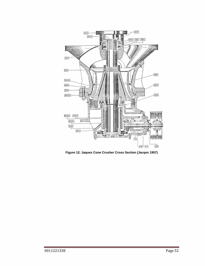
Figure 12: Jaques Cone Crusher Cross Section (Jacqes 1957)

0011221338 Page 53
No. Component or Sub System Description 112&114 Counter shaft(Pinion Shaft) bearings
135 Counter shaft 145 Countershaft oil seal 801 Top shell assembly 803 Spider cap 816 Head nut 819 Mantle wear liner 822 Concave wear liner 825 Dust seal ring 828 Crown wheel gear 841 Spider arm shield 847 Suspension nut assembly 868 Shell mounting bolts 880 Suspension nut assembly 882 Suspension nut assembly 883 Suspension nut assembly 895 Dust seal bonnet 8060 Bottom shell 8090 Eccentric assembly 8150 Main shaft 8270 Eccentric assembly 8992 Eccentric assembly
Table 7: Jaques Cone Crusher Parts List, reference Figure 12
CRUSHER PROTECTION SYSTEM
The crusher is fitted with protection systems. The crusher motor is electrically
interlocked, therefore the crusher drive motor will not start until the oil pump has
been started and the low oil flow sensor is not reading low oil flow. The low oil
flow sensor is located on the return side of the lube system, and so oil circulates
the entire system and is returned back to the tank, before the low oil flow sensor
does not read. This means that the crusher has sufficient lubrication and can be
started. The interlock now allows for the crusher motor to be started. This
interlock also works when operating the crusher; if the low oil flow sensor reads
low oil flow the crusher motor will stop, as there is a problem. (B Fitzpatrick
2009, pers. comm., 02 June.)
0011221338 Page 54
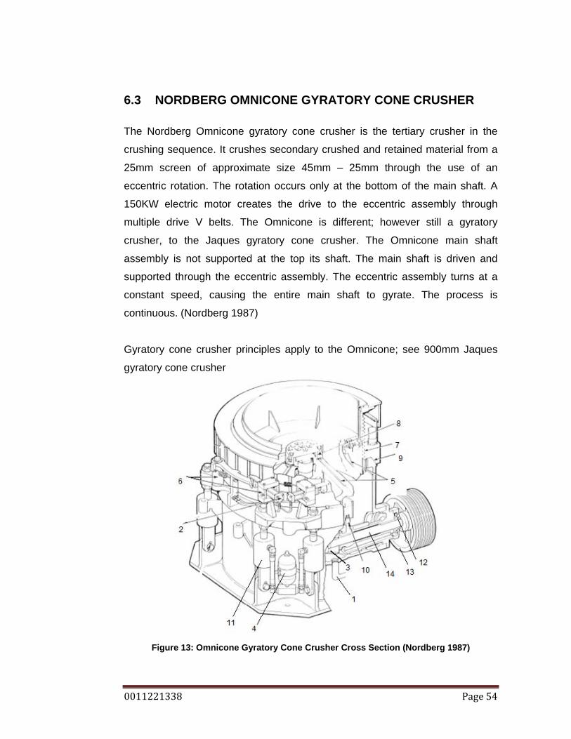
6.3 NORDBERG OMNICONE GYRATORY CONE CRUSHER
The Nordberg Omnicone gyratory cone crusher is the tertiary crusher in the
crushing sequence. It crushes secondary crushed and retained material from a
25mm screen of approximate size 45mm – 25mm through the use of an
eccentric rotation. The rotation occurs only at the bottom of the main shaft. A
150KW electric motor creates the drive to the eccentric assembly through
multiple drive V belts. The Omnicone is different; however still a gyratory
crusher, to the Jaques gyratory cone crusher. The Omnicone main shaft
assembly is not supported at the top its shaft. The main shaft is driven and
supported through the eccentric assembly. The eccentric assembly turns at a
constant speed, causing the entire main shaft to gyrate. The process is
continuous. (Nordberg 1987)
Gyratory cone crusher principles apply to the Omnicone; see 900mm Jaques
gyratory cone crusher
Figure 13: Omnicone Gyratory Cone Crusher Cross Section (Nordberg 1987)

0011221338 Page 55
No. Component or Sub System Description 1 Oil return line 2 Adjustment cylinders 3 Pinion and crown wheel gears 4 Tramp cylinder accumulators 5 Mantle and concave wear liners 6 Concave adjustment locking mechanism 7 Adjustment thread 8 Head nut cover 9 Top shell locking surface 10 Dust seal 11 Tramp cylinders 12 Pinion seal 13 Multi V belt pulley 14 Pinion shaft Table 8: Omnicone Gyratory Cone Crusher parts sheet, reference figure 13
As a tertiary crusher, the Omnicone uses a tertiary mantle and concave which
uses a more blunt profile mantle and concave than a secondary crusher mantle
and concave wear liner shape profile. The tertiary mantle and concave shape
limits the input size of material. As a tertiary crusher it also operates with a CSS
of approximately 15 – 18mm. Due to the tighter CSS and the tertiary profile the
material thro put, that amount of processed material is lower than the secondary
crusher. (N Bellamy 2009, pers. comm., 01 June.)
The Omnicone has 2 oil systems; a lube system and an adjustment system.
The lube system is identical to the Jaques system, oil is transferred from the
reservoir by the oil pump. The pump is driven by a speed reducer gearbox
which is connected to a 5KW electric motor. Oil then enters a filter, and then
through an oil cooler. The oil is forced air cooled, by way of a electric motor
driven fan. Oil then enters the crusher through the pinion housing. Oil flows
through the pinion housing to the crown wheel and through the eccentric
assembly. Oil is then gravity feed through a port in the bottom of the pinion
housing and back to the reservoir. (Nordberg 1987)

0011221338 Page 56
The adjustment system consists of 2 sub systems. A sub system is called the
tramp system. The tramp system holds the clamping ring to the main frame by
the use of 4 hydraulic cylinders; they are placed on 90 degree spacing around
the crusher body. Oil pressure is maintained in the cylinders to ensure that that
top shell of the crushers is held tightly against the mainframe. The tramp
release assembly incorporate an accumulator. There is an accumulator for each
hold down cylinder; the accumulator is used as a protection. If a metal object is
feed into the crusher oil pressure from the hold down cylinders will flow into the
accumulators and release the tramp, this will allow the top shell of the crusher
to rise and allow the metal object through the crusher without causing major
damage. (Nordberg 1987)
The second sub system is for the use of CSS adjustment. As the crusher
mantle and concave wear liners wear it must be adjusted to maintain the
desired output size rock. To adjust the Omnicone CSS, the tramp system
releases the pressure from the hold down cylinders, and by using the directional
control valves; oil is directed to the adjusting cylinders. The adjusting cylinders
contact the adjusting ring, and lock into the edges. The cylinder continues to
extend, pushing the adjusting ring. The adjusting ring is threaded on the inside
and as the adjusting ring turns, so does the concave height with the thread.
After the adjustment has occurred, the hold down cylinders regain pressure and
clamp the clamping ring to the main frame. (Nordberg 1987)
The tramping and adjustment oil system draw oil from the same reservoir,
through an electric driven oil pump.
CRUSHER PROTECTION SYSTEMS The crusher is fitted with a similar protection system as the Jaques crusher. The
crusher motor is electrically interlocked, therefore the crusher drive motor will
not start until the oil pump has been started and the low oil flow sensor is not
reading low oil flow. The low oil flow sensor is located on the return side of the
lube system, and so oil circulates the entire system and is returned back to the
0011221338 Page 57
tank, before the low oil flow sensor does not read. This means that the crusher
has sufficient lubrication and can be started. The interlock now allows for the
crusher motor to be started. This interlock also works when operating the
crusher; if the low oil flow sensor reads low oil flow the crusher motor will stop,
as there is a problem. (B Fitzpatrick 2009, pers. comm., 02 June.)
The Omnicone also has a temperature switch incorporated into its protection
system. The temperature switch specifications show that the electric motor can
not start until the oil is within the range 16 – 70 degrees Celsius. The
temperature switch is also used to switch the electric motor ON and OFF for the
cooling fan, it switched the fan ON at 40 degrees Celsius. (B Fitzpatrick 2009,
pers. comm., 02 June.)
6.4 BARMAC ROTOPACTOR (VSI)
The Barmac Rotopactor Vertical Shaft Impactor (VSI) consists of a feed tube,
rotor, crushing chamber, a bearing cartridge and a discharge chute. The rotor is
driven through multi drive V belts from a 200KW electric motor. The rotor is
spinning at approximately 1040rpm. The Barmac is called a rock ‘Shaper’ and
not a rock crusher because the 2 main reduction methods used by the Barmac
are attrition by glancing blows with other rocks and abrasion as the rocks
interact. Therefore the concept of the Barmac VSI is rock on rock shaping. (Allis
Tidco 1988)
The Ormeau Barmac is set up to have two inputs, one from screen 3, of size 25
– 5mm through chute 3, and the other from oversized material returning to the
surge bin for re crush, which is diverted into chute 23 by the adjustable gate 2.
Therefore, an input material summary is 25 – 5 mm. Once through the Barmac
material travels through transfer point 9 to conveyor 2.
The rock is continuously feed into the feed tube of the Barmac, which directs
material into the centre of the high speed spinning rotor, which throws the
0011221338 Page 58
material out, at a speed of 50-85m/s, as a continuous rock stream into the stone
lined crushing chamber. The material size reduction comes from the airborne
rock on rock interaction and the rock on rock interaction as the rotor accelerated
material hits the material build up on the sides of the crushing chamber. The
material build in the rotor and the crushing chamber are vital components to the
Barmac. The rotor and crushing chamber are lined with wear plates but rely on
material build up to protect the system from wear from the high speed material
interaction. Material once shaped is deposited through the discharge chutes
and onto the conveyor belt. (Allis Tidco 1988)
The rotor is at the centre of the VSI. It is mounted on a bearing cartridge which
consists of 2 radial bearings and a trust bearing, with 2 grease seals. The
bearing cartridge must be greased daily to the manufactures specifications of
15 grams of grease a day. (Allis Tidco 1988)

0011221338 Page 59
Figure 14: Barmac VSI Cross Section (Allis Tidco 1988)
No. Component or Sub System Description 1 Crushing chamber 2 Feed Tube 3 Rotor 4 Discharge chute 5 Bearing cartridge 6 Rotor wear plates.
Table 9: Barmac VSI Parts Sheet, see Figure 14
BARMAC PROTECTION SYSTEMS There are no protection systems for the Barmac systems, it is started and
stopped at the demand of the operator
0011221338 Page 60
6.5 MALCO VIBRATING SCREENS
The Ormeau plant uses 8 Malco vibrating screens. Vibrating screens are driven
by 7.5KW electric motors running at 1040rpm, the speed is reduced through
pulley ratios; the drive is transferred to the screen through dual drive V belts.
The V belts turn the main shaft of the screen, attached to the shaft is an offset
counterweigh. As the screen shaft turns the counterweigh causes a cyclic
weight imbalance, and the screen moves in an orbital motion. The orbital motion
together with the screen declination angle gives the material ‘throw’ and causes
the material to flow down the screen. The motion is accommodated by the
springs which are located on all 4 corners of the screen body. The vertical
motion allows for the vital concept of ‘Separation’ which either causes material
to be retained on a screen deck or screened though the screen deck (Malco
1986). The process is continuous except for screen 1, which is turned on and
off by the operator to control the amount of material going into the primary jaw
crusher.
Screen 1 instead of using a direct drive from the drive V belts uses a fluid
coupling. The fluid coupling allows for a soft start and also as a load dampener.
Since screen 1 is stop started approximately 30 times in an hour with material
on the screen, to not overload the motor, it needs to be soft started and also an
amount of drive slippage between the motor and the screen.
The fluid coupling is oil filled. Once the electric motor is started the impeller
begins to turn. Oil is thrown outward strikes the vanes of the turbine causing
the turbine to rotate. Therefore power is transferred through the fluid between
the input and output. The turbine is connected directly to the driver v belt
pulleys. The fluid coupling is not to be confused with a torque converter. The
difference being the angle of the turbine vanes.

0011221338 Page 61
Figure 15: Fluid Coupling Cross Section (Bennett & Norman 2006)
Figure 16: Vibrating Screen General Assembly (Malco 1986)
Figure 17: Vibrating Screen Operational. (Malco 1986)
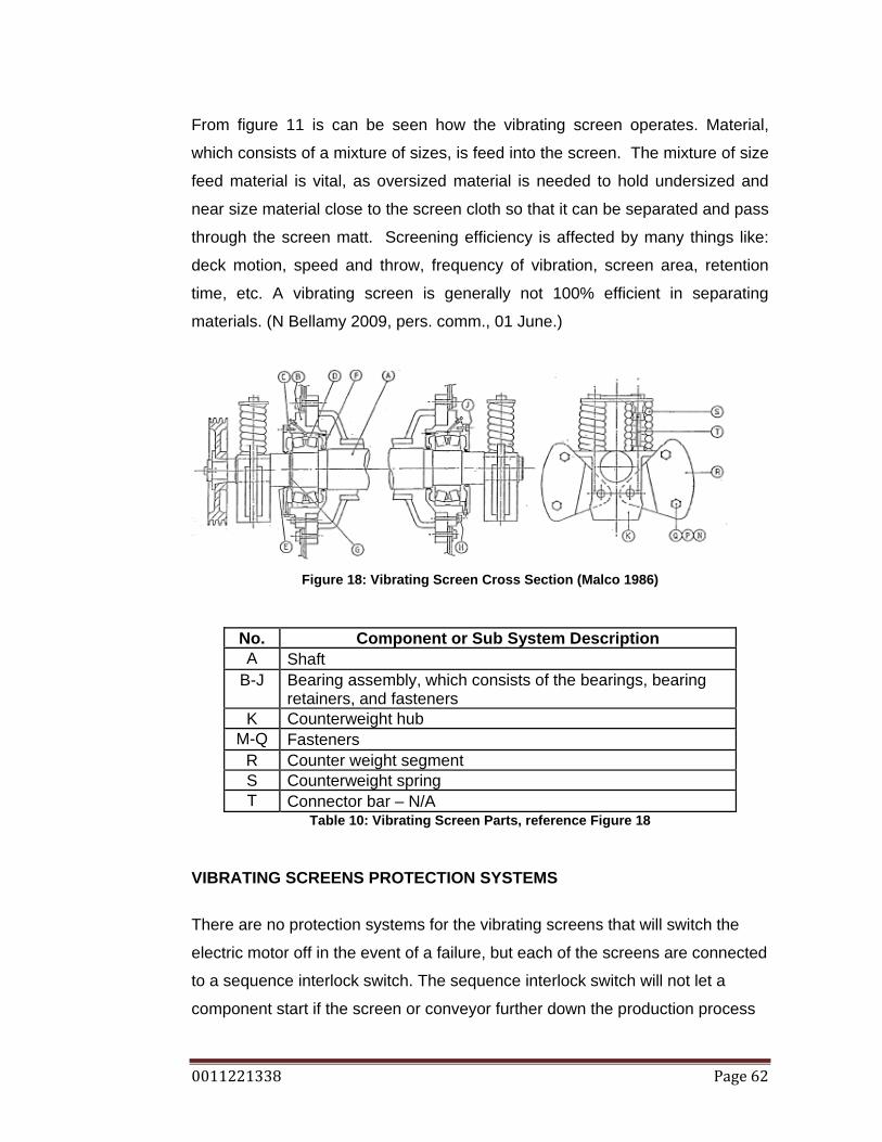
0011221338 Page 62
From figure 11 is can be seen how the vibrating screen operates. Material,
which consists of a mixture of sizes, is feed into the screen. The mixture of size
feed material is vital, as oversized material is needed to hold undersized and
near size material close to the screen cloth so that it can be separated and pass
through the screen matt. Screening efficiency is affected by many things like:
deck motion, speed and throw, frequency of vibration, screen area, retention
time, etc. A vibrating screen is generally not 100% efficient in separating
materials. (N Bellamy 2009, pers. comm., 01 June.)
Figure 18: Vibrating Screen Cross Section (Malco 1986)
No. Component or Sub System Description A Shaft
B-J Bearing assembly, which consists of the bearings, bearing retainers, and fasteners
K Counterweight hub M-Q Fasteners
R Counter weight segment S Counterweight spring T Connector bar – N/A
Table 10: Vibrating Screen Parts, reference Figure 18
VIBRATING SCREENS PROTECTION SYSTEMS
There are no protection systems for the vibrating screens that will switch the
electric motor off in the event of a failure, but each of the screens are connected
to a sequence interlock switch. The sequence interlock switch will not let a
component start if the screen or conveyor further down the production process

0011221338 Page 63
is not running first. The advantage of this is that a component that is not running
will not be filled with material. Once the component gets filled with material, it
must be removed by hand. (B Fitzpatrick 2009, pers. comm., 02 June.)
6.6 MATERIAL HANDLING CONVEYORS Material handling conveyors are used throughout the plant. They are of different
sizes, inclines, declines, handle different amounts and sizes of material, and run
at different speeds. The conveyor systems used in the Ormeau plant utilize the
same components.
The conveyor belts used in the Ormeau plant are large rubber bands stretched
between 2 pulleys, one called the head drum which is where the conveyor
discharges is, and the other being the tail drum, which is where the loading
occurs. They travel at a consistent speed. The belt is supported between the
head and tail drums by the use of trough rollers. The trough rollers are a system
of 3 rollers, 1 in the middle of the belt which is flat and the side 2 which are set
up an angle of 30 degrees. This angle is used to increase the capacity of the
belt. The bottom of the conveyor belt, or the return side, is supported with return
rollers which are flat. Drive to the conveyor is provided at the head of the
conveyor through an electric motor coupled through the use of v belts to a
speed reduction gear box. The size of the electric motor and the ratio of the
gearbox vary depending on weight carried and the operating angle of the
conveyor. (Swinderman, Goldbeck, Marti 2002)
Tension is provided to the conveyor belt through mechanical means. Threaded
rods attached to the tail drum, which when adjusted apply tension to the belt.
This system is also used to align the belt, and allow it to run straight between
the trough rollers.

0011221338 Page 64
Figure 19: Conveyor General Arrangement (Swinderman, Goldbeck, Marti 2002)
Ancillary components are used to clean the belt like: belt scrappers, and tail
pulley plow scrappers. Belt scrappers, scrap the outside of the belt and are
positioned so that the scrapings go with the flow of material. Pulley plow
scrappers are located at the tail drum, on the inside of the belt, with a function
to scrap material from the belt and direct it off the edges of the belt so that it
does not run in between the tail pulley and the belt and potentially cause
damage.
MATERIAL HANDLING CONVEYOR PROTECTION SYSTEMS Like vibrating screens there are no protection systems for the conveyors that
will switch the electric motor off in the event of a failure, but each of the
conveyors are connected to a sequence interlock switch. Refer: Vibrating
screens protection systems for details of the sequence interlock.
6.7 MATERIAL HANDLING TRANSFER POINTS
Material handling transfer points transfer material off of material handling
conveyor belts and onto another conveyor belt. They consist of a delivery chute
which directs material off the preceding conveyor and onto the next conveyor
belt. Transfer points also seal the delivery chute to the loading zone of the next

0011221338 Page 65
conveyor belt through the use of rubber dust seals which are adjustable and
must make good contact with the conveyor belt to ensure that the material stays
on the belt. Refer to figure 18 to observe the load chute, skirt board and dust
seal configurations. (Swinderman, Goldbeck, Marti 2002)
Transfer points are lined with sacrificial wear liners made of high grade steel,
and must be replaced when the wear plate is becoming thin enough that they
do not do their intended job.
Transfer points are also prone to blockages due to material build up.
MATERIAL HANDLING TRANSFER POINT PROTECTION SYSTEMS There are no protection systems for material handling transfer points. In the
event of a blockage, it is up to the operator to visually see the overflowing
material.
6.8 MATERIAL HANDLING CHUTES Material handling chute direct material into components like aggregate storage
bins, the surge bin, the Barmac. Chutes do not deliver material onto conveyors,
but can direct material away from conveyors and screens. Chutes are lined with
sacrificial wear liners. (Swinderman, Goldbeck, Marti 2002)
MATERIAL HANDLING CHUTE PROTECTION SYSTEMS
There are no protection systems for material handling chutes. In the event of a
blockage, it is up to the operator to visually see the overflowing material.
6.9 AGGREGATE STORAGE BINS The Ormeau plant has 16 storage bins. The bins are delivered final product
aggregates and hold them until the material is emptied by the bin truck operator.
The storage bins are lined with a sacrificial wear liners made of high grade
0011221338 Page 66
steel. The bins also use a bin gate, which is a 2 gate system, geared together
and rotate on bearings.
AGGREGATE STORAGE BIN PROTECTION SYSTEMS
The protection system for the aggregate storage bins to protect against material
overflow is the bin level switch system.
6.10 SURGE BIN
The surge bin temporarily holds secondary crusher material. The surge bin
feeds conveyor 11 through transfer point 8 which travels directly to the
Omnicone for tertiary crushing. The surge bin is lined with a sacrificial wear liner
made of high grade steel.
SURGE BIN PROTECTION SYSTEMS There are no protection systems for the surge bin.
6.11 TIPPING BIN The tipping bin is the transfer point between the load and haul and the crushing
plant. It is a live tipping bin, meaning that it has a steep floor that gravity feeds
material into the plant. It is lined with sacrificial wear liners. TIPPING BIN PROTECTION SYSTEMS There are no protection systems for the tipping bin.
6.12 AGGREGATE BIN LEVEL SENSOR Each aggregate bin has a bin level sensor. The sensor is called a ‘Tilt Switch’,
which as the material level inside the bin rises, it eventually raises enough to
build up under the level sensor which tilts the switch and connect the circuit.
The circuit is connect to an indicator light, which lets the bin truck operator know

0011221338 Page 67
that the bin is full and needs to be emptied. (B Fitzpatrick 2009, pers. comm., 02
June.)
AGGREGATE BIN LEVEL SENSOR PROTECTION SYSTEM
There is no protection system for the aggregate bin level system.
6.13 AGGRGATE STORAGE BIN GATE OPENING SYSTEM The aggregate storage bins must be emptied constantly as they fill up. The
capacity of the bins are 28 tonnes each. The bin gate opening system is a
wireless system that operates the directional control valves for each separate
bin, which then opens the bin gate actuator. The advantage of the wireless
system is that the bin truck operator does not need to stop and vacate the truck
to open bin gates. When a particular bin is full the bin truck operator places the
bin truck body under the bin gate, they then select the bin that they wish to
empty on the transmitter mounted in the truck, they send the signal to open the
bin to the receiver and the receiver operates the directional control valve which
sends air to the selected pneumatic cylinder, which opens the gate. (B
Fitzpatrick 2009, pers. comm., 02 June.)
AGGREGATE BIN GATE OPENING SYSTEM PROTECTION SYSTEM
There is no protection system for the bin gate system.
6.14 THE AGGREGATE BIN TRUCK
The aggregate bin truck empties the aggregate bins. The bin trucks
continuously empty the aggregate bins. The bin trucks are 12 tonne body trucks
and are only serviceable by trained personnel. Due to the plant capacity, one
bin truck is needed to service all bins.
BIN TRUCK PROTECTION SYSTEM

0011221338 Page 68
The bin truck has protection systems in the way of engine management
systems, but are unserviceable by BORAL staff.
6.15 DUST SUPPRESION SYSTEM
The dust suppression system uses a water pump to draw water from a storage
dam through a filter to a storage tank located at the crushing plant. Another
water pump draws water from the storage tank though a filter, and delivers the
water to a manifold located at the plant control room. The manifold is operated
by the plant operator, who can turn water on to different parts of the plant as
needed to keep the airborne dust contaminates to a minimum
DUST SUPPRESSION PROTECTION SYSTEM There is no protection system for the dust suppression system
6.16 COMP AIR ROCK BREAKER
The Comp air rock breaker is a hydraulic impactor. It is used to dislodge or
break large rocks that fall awkwardly into the jaw and jam, or are simply too big
to go through. The rock breaker is boom mounted and is situated beside the jaw
crusher. When the Jaw becomes blocked, the plant operator will operate the
rock breaker and free the Jaw input.
The rock breaker uses a simple hydraulic circuit; an open centre system, with
the hydraulic pump connected to an electric motor, the oil flows through a filter
to the directional control valves, and back through an oil cooler and to tank. The
direction control valves are lever actuated. The system is not running
constantly, it is only turned on when needed.
COMP AIR ROCK BREAKER PROTECTION SYSTEM
There is no protection system for the rock breaker.

0011221338 Page 69
6.17 ATLAS COPCO AIR COMPRESSOR The air compressor supplies the plant with air. The system has 3 air receivers, 2
remote mounted on the plant to service the bin gate actuators for faster
operation. The air compressor is a complete unit and is unserviceable by
untrained personnel.
6.18 AS/NZ 3000 AND AS3007
Under the Australian standard, AS/NZ 3000 AND AS3007, electrical systems
used throughout the plant, are only serviceable by trained, qualified electricians
and this is definitely the case at the Ormeau site. (IQA 2009)
Also under AS/NZ 3000 and AS3007, all electrical components must be fitted
with current overload switches, which must be matched to each system
separately, and the trip time for the overload must be no greater than 30ms.
The main function of both of these devices is the safety factor, but it also acts
as a protection system. Other objectives of AS/NZ3000 is the prevention of
electric shock, prevention of excess temperatures, and the prevention of
explosions. Other objectives set by AS3007 is the guarding principles. The
Electrician that is contracted to work on the Ormeau plant is fully aware of all
standards, and has shown this in a tender evaluation process to win the job.
(IQA 2009)
6.19 CHAPTER SUMMARY In previous chapters the critical path of the plant was determined, and found it
to be all machines used in the crushing and screening process. This chapter
outlined the parts involved and the how each machine operates. It identified any
protection systems currently in use.

0011221338 Page 70
7. DEVELOPMENT OF FUNCTIONAL DIAGRAMS
Functional diagrams were developed to show the functional breakdown of
elements in the system and sub systems, they provide technical understanding;
show any series, superfluous relationships.
Once the assembly, or system interactions are known, it will be possible to
understand which components may fail, and stop the overall machine which will
stop the plant, as it was discovered in production process study, or which
components may fail and still allow the machine to continue operation. This
information is important to the FMECA process, as it will directly relate to the
‘Effect of a failure’.
7.1 FUNCTIONAL DIAGRAMS
To assist in the analysis of the crushing and screening plant, functional
diagrams were constructed. All machines that were considered in chapter 9 will
be analysed.
The functional diagrams will be used to show the interactions of the systems
and sub systems together with the various sub assemblies. To make sure that
the functional diagrams remain concise, sub-assemblies have been used. The
sub assemblies have been detailed in the tables to show which components are
included in the assemblies.
Within each system and sub system, different interactions occur. Within the
functional diagrams these interaction will be modeled. The different interactions
will be categorized into: structural support, wear protection, lubricant supply,
and power transmission (Mechanical/electrical/hydraulic). This interaction will
be shown in the legend below.
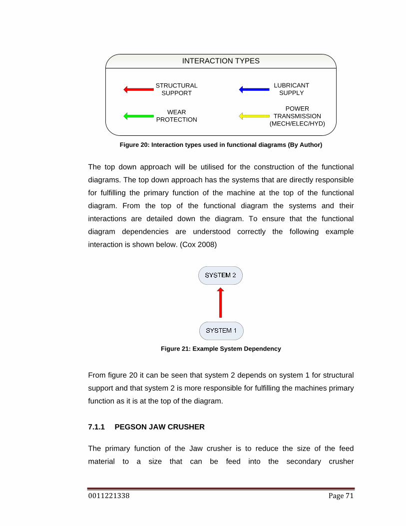
0011221338 Page 71
INTERACTION TYPES
STRUCTURAL SUPPORT
WEAR PROTECTION
LUBRICANT SUPPLY
POWER TRANSMISSION
(MECH/ELEC/HYD)
Figure 20: Interaction types used in functional diagrams (By Author)
The top down approach will be utilised for the construction of the functional
diagrams. The top down approach has the systems that are directly responsible
for fulfilling the primary function of the machine at the top of the functional
diagram. From the top of the functional diagram the systems and their
interactions are detailed down the diagram. To ensure that the functional
diagram dependencies are understood correctly the following example
interaction is shown below. (Cox 2008)
Figure 21: Example System Dependency
From figure 20 it can be seen that system 2 depends on system 1 for structural
support and that system 2 is more responsible for fulfilling the machines primary
function as it is at the top of the diagram.
7.1.1 PEGSON JAW CRUSHER
The primary function of the Jaw crusher is to reduce the size of the feed
material to a size that can be feed into the secondary crusher

0011221338 Page 72
<http://www.aggdesigns.com/Jaw-Crusher-info.htm>. At the top of the functional
diagram is the fixed jaw wear liner and the swing jaw wear liner. The fixed jaw
relies on the structural backing frame to give a solid crushing surface, and the
fixed jaw wear liner is held in place by bolts. The swing jaw wear liner is
attached to the structural frame, and held in place by bolts, which is driven by
the eccentric shaft. The eccentric shaft gives the motion to create nip points for
crushing to occur. The lower end of the swing jaw relies on the toggle system
for its movement, rigidity and adjustment. Continuous drive motion is provided
through the electric motor, V belts, and momentum is conserved by the large
flywheels which are mounted on either side of the parallel shaft. See figure 8.
Figure 22: Flow diagram for Jaw Crusher (By author)

0011221338 Page 73
Component or Sub System Description Swing jaw liner Fixed jaw liner Jaw frame which includes: Fixed jaw pad, swing jaw pad, structural frame, and wear liner mounting bolts. Crushing chamber wear liners, also called cheek plates and mounting bolts Toggle assembly, which consists of :Jaw crusher toggle block, tension rod with spring, toggle plate and toggle seats Eccentric shaft assembly which includes: eccentric shaft, shaft bearings, eccentric bushing. Flywheels which includes: pulley and flywheel and mounting bolts. V belts: 6 belt system Electric motor: 110KW
Table 11: Jaw Crusher Sub Assembly Details, reference Figure 22 MACHINE SUMMARY The jaw crusher uses the fixed and swing jaw wear liners to perform its primary
function of reducing the input size of rock. Continuous movement is provided to
the swing jaw wear liner through the eccentric shaft, which is driven by V belts
and an electric motor.
CRITICAL MACHINE ITEMS It can be seen by studying the functional diagram, the parts sheet, and the
operation of the Jaw Crusher, that all components all vital to the running of the
entire machine, and further more the plant. The system can finish a shift with
slight defects for example: 1 V belt broken, slight wear liner mounting problems,
or slight framing cracks, with constant monitoring and full repairs to take place
in a planned manner.
7.1.2 900MM JAQUES GYRATORY CONE CRUSHER
The primary function of a cone crusher is to reduce the size of the feed material
to a desired range of output sizes through compression of the material (Jacques
1957). This function is performed by the mantle and concave wear liners which
are shown at the top of the functional diagram. The mantle is connected to the
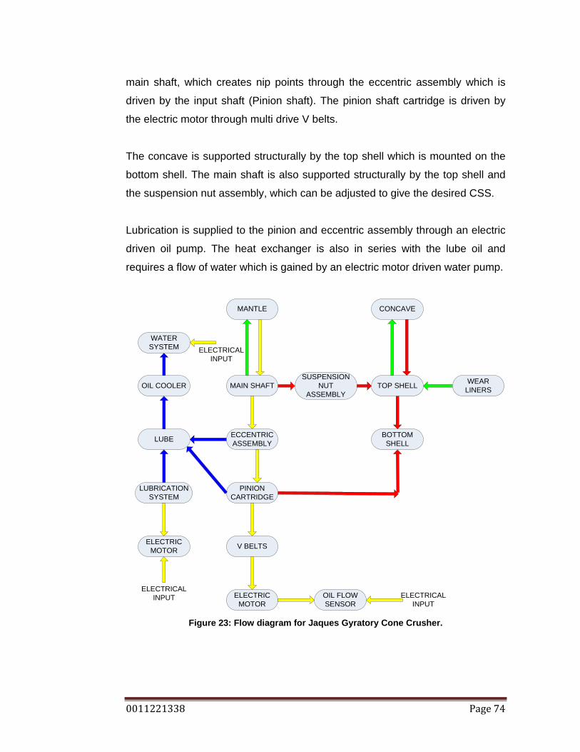
0011221338 Page 74
main shaft, which creates nip points through the eccentric assembly which is
driven by the input shaft (Pinion shaft). The pinion shaft cartridge is driven by
the electric motor through multi drive V belts.
The concave is supported structurally by the top shell which is mounted on the
bottom shell. The main shaft is also supported structurally by the top shell and
the suspension nut assembly, which can be adjusted to give the desired CSS.
Lubrication is supplied to the pinion and eccentric assembly through an electric
driven oil pump. The heat exchanger is also in series with the lube oil and
requires a flow of water which is gained by an electric motor driven water pump.
MANTLE CONCAVE
MAIN SHAFT
ECCENTRIC ASSEMBLY
PINIONCARTRIDGE
TOP SHELL
V BELTS
ELECTRIC MOTOR
BOTTOMSHELL
SUSPENSION NUT
ASSEMBLY
ELECTRICALINPUT
OIL FLOWSENSOR
LUBE
LUBRICATIONSYSTEM
ELECTRIC MOTOR
ELECTRICALINPUT
OIL COOLER
WATERSYSTEM ELECTRICAL
INPUT
WEAR LINERS
Figure 23: Flow diagram for Jaques Gyratory Cone Crusher.
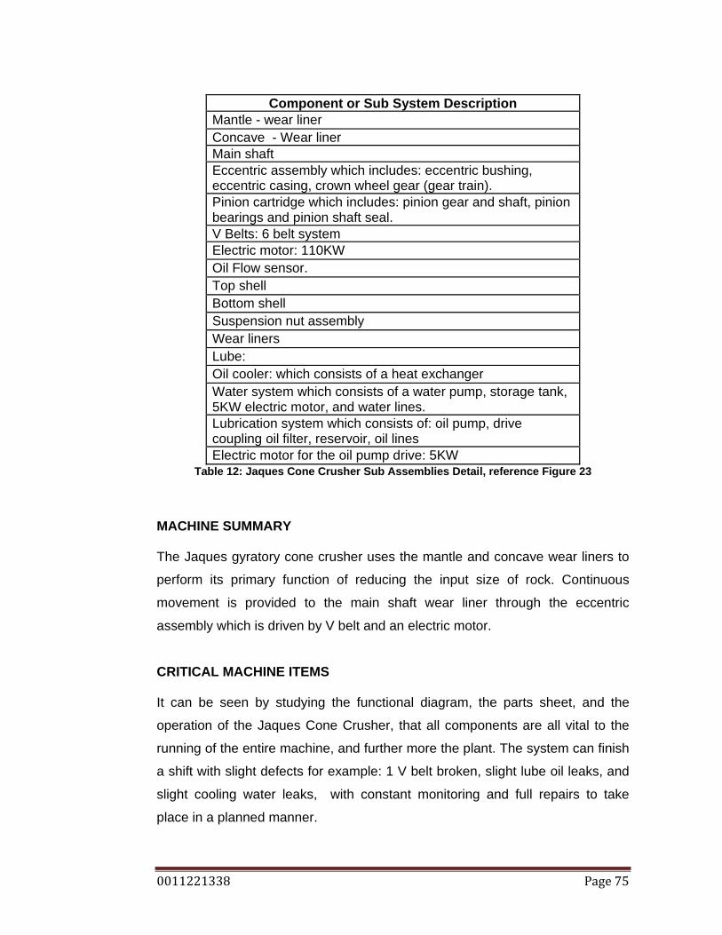
0011221338 Page 75
Component or Sub System Description Mantle - wear liner Concave - Wear liner Main shaft Eccentric assembly which includes: eccentric bushing, eccentric casing, crown wheel gear (gear train). Pinion cartridge which includes: pinion gear and shaft, pinion bearings and pinion shaft seal. V Belts: 6 belt system Electric motor: 110KW Oil Flow sensor. Top shell Bottom shell Suspension nut assembly Wear liners Lube: Oil cooler: which consists of a heat exchanger Water system which consists of a water pump, storage tank, 5KW electric motor, and water lines. Lubrication system which consists of: oil pump, drive coupling oil filter, reservoir, oil lines Electric motor for the oil pump drive: 5KW
Table 12: Jaques Cone Crusher Sub Assemblies Detail, reference Figure 23
MACHINE SUMMARY The Jaques gyratory cone crusher uses the mantle and concave wear liners to
perform its primary function of reducing the input size of rock. Continuous
movement is provided to the main shaft wear liner through the eccentric
assembly which is driven by V belt and an electric motor.
CRITICAL MACHINE ITEMS It can be seen by studying the functional diagram, the parts sheet, and the
operation of the Jaques Cone Crusher, that all components are all vital to the
running of the entire machine, and further more the plant. The system can finish
a shift with slight defects for example: 1 V belt broken, slight lube oil leaks, and
slight cooling water leaks, with constant monitoring and full repairs to take
place in a planned manner.

0011221338 Page 76
7.1.3 NORDBERG OMNICONE GYRATORY CONE CRUSHER The primary function of the Omnicone, like the Jaques gyratory crusher, is to
further reduce the size of the feed rock to a desired rock size through fracturing
the material (Nordberg 1987). Again like the Jaques this function is performed
through the mantle and concave, with the gyration caused by the eccentric
assembly, which produces it movement through the pinion shaft, V belts and an
electric motor. Structurally the concave is supported by the bowl, which is
supported by the adjustment assembly and held in place by the tramp release
system. The tramp release system relies on an electric motor driven oil pump.
The tramp release system relies on the bottom shell for structural support.
Lubrication is supplied through the lube pump, which driven through a speed
reducer and an electric motor. Oil is cooled by a fan cooled oil cooler. The fan is
driven by an electric motor.
The CSS adjustment relies on the adjustment system, which is supplied oil flow
by the same oil pump as the tramp release system.

0011221338 Page 77
Figure 24: Flow diagram for Omnicone Gyratory Cone Crusher.
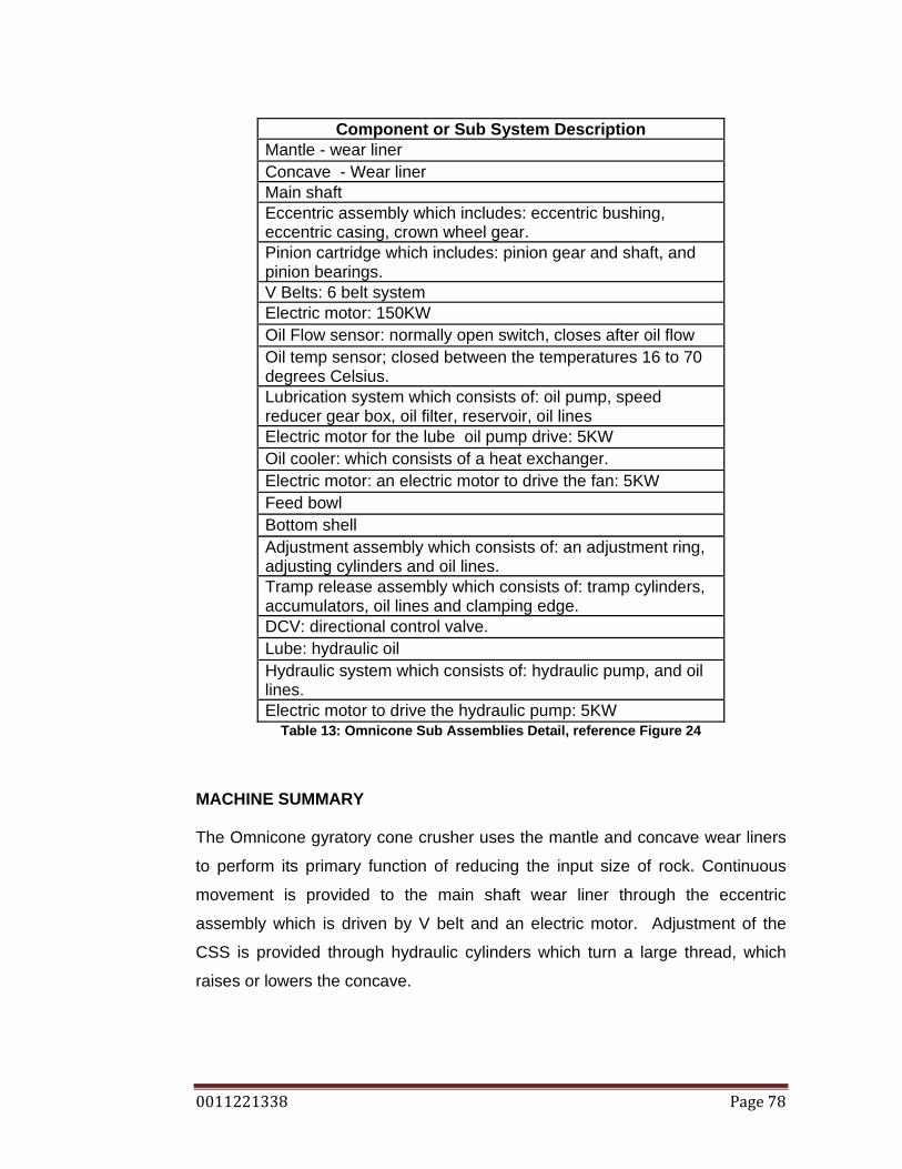
0011221338 Page 78
Component or Sub System Description Mantle - wear liner Concave - Wear liner Main shaft Eccentric assembly which includes: eccentric bushing, eccentric casing, crown wheel gear. Pinion cartridge which includes: pinion gear and shaft, and pinion bearings. V Belts: 6 belt system Electric motor: 150KW Oil Flow sensor: normally open switch, closes after oil flow Oil temp sensor; closed between the temperatures 16 to 70 degrees Celsius. Lubrication system which consists of: oil pump, speed reducer gear box, oil filter, reservoir, oil lines Electric motor for the lube oil pump drive: 5KW Oil cooler: which consists of a heat exchanger. Electric motor: an electric motor to drive the fan: 5KW Feed bowl Bottom shell Adjustment assembly which consists of: an adjustment ring, adjusting cylinders and oil lines. Tramp release assembly which consists of: tramp cylinders, accumulators, oil lines and clamping edge. DCV: directional control valve. Lube: hydraulic oil Hydraulic system which consists of: hydraulic pump, and oil lines. Electric motor to drive the hydraulic pump: 5KW
Table 13: Omnicone Sub Assemblies Detail, reference Figure 24
MACHINE SUMMARY
The Omnicone gyratory cone crusher uses the mantle and concave wear liners
to perform its primary function of reducing the input size of rock. Continuous
movement is provided to the main shaft wear liner through the eccentric
assembly which is driven by V belt and an electric motor. Adjustment of the
CSS is provided through hydraulic cylinders which turn a large thread, which
raises or lowers the concave.

0011221338 Page 79
CRITICAL MACHINE ITEMS It can be seen by studying the functional diagram, the parts sheet, and the
operation of the Omnicone Crusher, that all components are all vital to the
running of the entire machine, and further more the plant. The system can finish
a shift with slight defects for example: 1 V belt broken, slight lube oil leaks, with
constant monitoring and full repairs to take place in a planned manner. The
system can operate if the hydraulic adjusting system has failed for a period of
time, the failure scope being that the CSS cannot be adjusted. The period being
approximately 1-2 shifts, as the plant become inefficient to run if the Omnicone
CSS is too large, as the output rock size is mostly being return for further
crushing cycles.
7.1.4 BARMAC ROTOPACTOR (VSI)
The primary function of the Barmac Rotopactor VSI is to shape the rock and to
further reduce the size of the feed material (Allis Tidco 1988). The component
that gives the rock its motion to reduce its size is the Rotor, this is shown at the
top of the functional diagram. The rotor is supported by the bearing cartridge,
which also allows the rotor to spin. The bearing cartridge relies on lubrication.
Drive to the bearing cartridge is provided through multiple drive V belts and an
electric motor. Structurally the bearing cartridge is supported by the Barmac
frame. The Barmac rotor and internal body relies on wear plates to protect the
components from unnecessary wear.
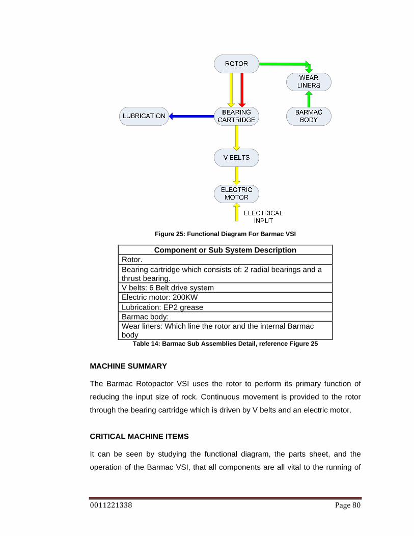
0011221338 Page 80
Figure 25: Functional Diagram For Barmac VSI
Component or Sub System Description
Rotor. Bearing cartridge which consists of: 2 radial bearings and a thrust bearing. V belts: 6 Belt drive system Electric motor: 200KW Lubrication: EP2 grease Barmac body: Wear liners: Which line the rotor and the internal Barmac body
Table 14: Barmac Sub Assemblies Detail, reference Figure 25
MACHINE SUMMARY
The Barmac Rotopactor VSI uses the rotor to perform its primary function of
reducing the input size of rock. Continuous movement is provided to the rotor
through the bearing cartridge which is driven by V belts and an electric motor.
CRITICAL MACHINE ITEMS It can be seen by studying the functional diagram, the parts sheet, and the
operation of the Barmac VSI, that all components are all vital to the running of
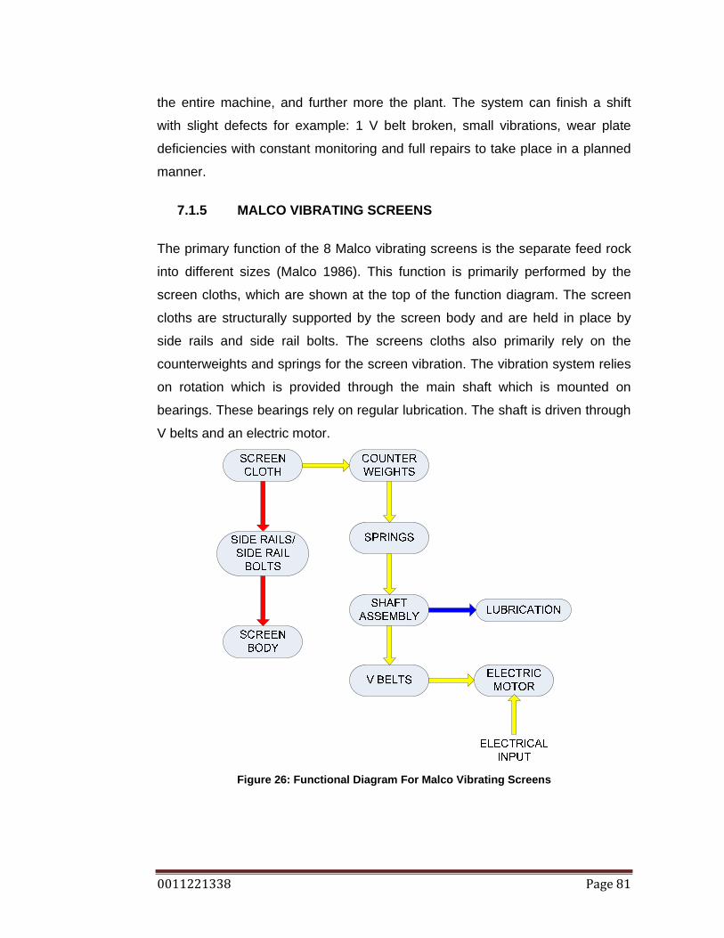
0011221338 Page 81
the entire machine, and further more the plant. The system can finish a shift
with slight defects for example: 1 V belt broken, small vibrations, wear plate
deficiencies with constant monitoring and full repairs to take place in a planned
manner.
7.1.5 MALCO VIBRATING SCREENS
The primary function of the 8 Malco vibrating screens is the separate feed rock
into different sizes (Malco 1986). This function is primarily performed by the
screen cloths, which are shown at the top of the function diagram. The screen
cloths are structurally supported by the screen body and are held in place by
side rails and side rail bolts. The screens cloths also primarily rely on the
counterweights and springs for the screen vibration. The vibration system relies
on rotation which is provided through the main shaft which is mounted on
bearings. These bearings rely on regular lubrication. The shaft is driven through
V belts and an electric motor.
Figure 26: Functional Diagram For Malco Vibrating Screens
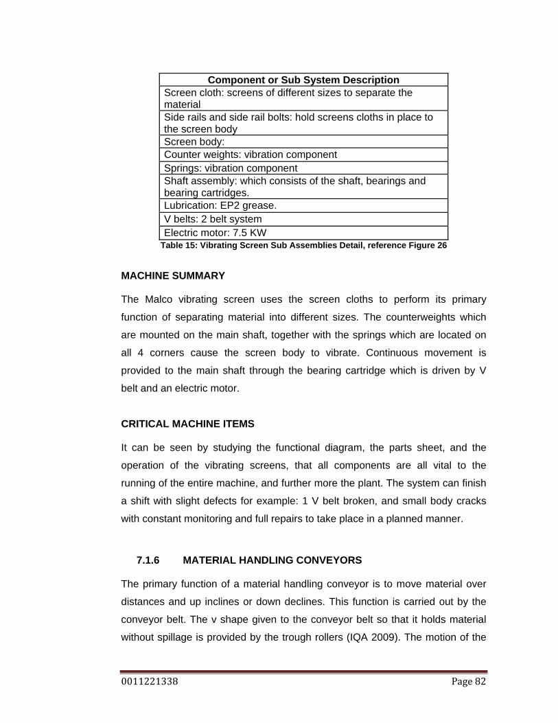
0011221338 Page 82
Component or Sub System Description Screen cloth: screens of different sizes to separate the material Side rails and side rail bolts: hold screens cloths in place to the screen body Screen body: Counter weights: vibration component Springs: vibration component Shaft assembly: which consists of the shaft, bearings and bearing cartridges. Lubrication: EP2 grease. V belts: 2 belt system Electric motor: 7.5 KW
Table 15: Vibrating Screen Sub Assemblies Detail, reference Figure 26
MACHINE SUMMARY
The Malco vibrating screen uses the screen cloths to perform its primary
function of separating material into different sizes. The counterweights which
are mounted on the main shaft, together with the springs which are located on
all 4 corners cause the screen body to vibrate. Continuous movement is
provided to the main shaft through the bearing cartridge which is driven by V
belt and an electric motor.
CRITICAL MACHINE ITEMS It can be seen by studying the functional diagram, the parts sheet, and the
operation of the vibrating screens, that all components are all vital to the
running of the entire machine, and further more the plant. The system can finish
a shift with slight defects for example: 1 V belt broken, and small body cracks
with constant monitoring and full repairs to take place in a planned manner.
7.1.6 MATERIAL HANDLING CONVEYORS
The primary function of a material handling conveyor is to move material over
distances and up inclines or down declines. This function is carried out by the
conveyor belt. The v shape given to the conveyor belt so that it holds material
without spillage is provided by the trough rollers (IQA 2009). The motion of the

0011221338 Page 83
conveyor belt is provided through a speed reducer which is connected to the
head drum roller, which is supported by bearings. The speed reducer is driven
through V belts and an electric motor. The tail end of the conveyor belt is also
supported by a tail drum roller, which is supported by bearings. The conveyor
belt alignment is provided by the tail drum roller allowing for adjustment.
Conveyor belt tracking is also effected by return rollers.
The conveyor belt and all supporting components rely structurally on a frame.
CONVEYOR BELT
TROUGH ROLLERS
HEAD DRUM ASSEMBLY
TAIL DRUM ASSEMBLY
GEAR BOX
V BELTS
ELECTRIC MOTOR
LUBRICATIONLUBRICATION
ELECTRICALINPUT
STRUCTURAL FRAME
STRUCTURAL FRAME
LUBRICATION
Figure 27: Functional diagram for Conveyor system by Author.

0011221338 Page 84
Component or Sub System Description Conveyor belt: belt rubber of different sizes Trough rollers: give the belt the V shape and allow the belt to carry more material. Head drum assembly: consists of the head drum and 2 sets of bearings, one on either side of the drum Tail drum assembly: consists of the tail drum and 2 sets of bearings, one on either side of the drum Gear box: speed reducer of different ratios V belts: 3 belt system, that links the electric motor and the gearbox Electric motor: Sizes range from 30KW to 7.5kW Head/tail drum bearing lubrication: EP2 grease Gearbox lubrication: gear oil Structural frame:
Table 16: Material Handling Conveyor Sub Assemblies Detail reference Figure 27
MACHINE SUMMARY Material handling conveyors use the conveyor belt to perform its primary
function of transferring material. The belt is shaped by the trough rollers and
over the head and tail rollers. Continuous movement is provided to the conveyor
through the use of speed reducing gear boxes driven through V belts by an
electric motor.
CRITICAL MACHINE ITEMS It can be seen by studying the functional diagram, the parts sheet, and the
operation of the material handling conveyors, that not all components are all
vital to the running of the entire machine. Components that can fail and still
allow full operation of the conveyor include: trough rollers, trough rollers can fail
and allow operation, but do pose a threat to cutting the rubber conveyor belt.
The system can finish a shift with slight defects for example: 1 V belt broken,
slight lube oil leaks on the speed reducing gearbox, small cracks in the
structural framing and a head or tail drum bearing failure can still allow
operation, with a risk to structural and belt damage, with constant monitoring
and full repairs to take place in a planned manner.

0011221338 Page 85
7.1.7 MATERIAL HANDLING TRANSFER POINTS
The primary function of a transfer point is to transfer material off one conveyor
and onto another conveyor (Swinderman, Goldbeck, Marti 2002). This function
is performed by the delivery chute, which is lined with sacrificial wear liners; the
delivery chute is shown at the top of the functional diagram. Material
containment is also provided through rubber dust seals. The entire transfer
point is supported structurally.
Figure 28: Functional Diagram For Material Handling Transfer Points System
Component or Sub System Description Delivery chute: chute that directs material from a conveyor to another conveyor Wear liners: the delivery chute is lined with sacrificial wear liners. Dust seals: contain material inside the transfer point, Structural frame
Table 17: Material Handling Transfer point Sub Assemblies Detail, reference Figure 28
MACHINE SUMMARY Material handling transfer points use the delivery chute to perform its primary
function of transferring material.
CRITICAL MACHINE ITEMS It can be seen by studying the functional diagram, the parts sheet, and the
operation of the transfer points, that all components are vital to the operation of

0011221338 Page 86
the component. It is permissible to continue running the plant if dust seals are
worn and leaking material but it is not desirable, as it requires clean up costs.
7.1.8 MATERIAL HANDLING CHUTES
The primary function of a chute is to deliver material off various components like
screens and conveyors onto other components like: aggregate bins, surge bins.
This function is carried out by the chute, which is lined with a sacrificial wear
liner. Chutes are also supported structurally. (Swinderman, Goldbeck, Marti
2002).
Figure 29: Functional diagram for Material Handling Chutes
Component or Sub System Description Delivery chute: chute that directs material Wear liners: the delivery chute is lined with sacrificial wear liners. Structural frame.
Table 18: Material Handling Chutes Sub Assemblies Detail, reference Figure 29
MACHINE SUMMARY
Material handling chutes use the delivery chute to perform its primary function
of transferring material.
CRITICAL MACHINE ITEMS It can be seen by studying the functional diagram, and the operation of material
handling chutes that all components are required for the operation of the chute.

0011221338 Page 87
7.1.9 AGGREGATE STORAGE BINS The primary function of the aggregate storage bins is to store aggregates. The
component that performs this function is the bin walls, which are lined with
sacrificial wear liners. The storage bins are emptied by the bin gates. The bin
gates rely on sealed bearings for rotation.
The aggregate storage bins are supported by structural frames.
Figure 30: Functional diagram for Aggregate Storage Bins
Component or Sub System Description Bin walls: The walls that make up the bin. Wear liners: the internal bin walls are lined with sacrificial wear liners. Structural frame.
Table 19: Aggregate Storage Bin Sub Assemblies Detail reference Figure 30
MACHINE SUMMARY
Aggregate storage bins use the bin walls to perform its primary function of
holding and storing material.
CRITICAL MACHINE ITEMS It can be seen by studying the functional diagram, and the operation of the
aggregate storage bins that all components are required for the operation of the
component.

0011221338 Page 88
7.1.10 SURGE BIN The primary function of the surge bin is to store secondary crushed and
screened material before it travels to the tertiary crusher. The component that
performs this function is the bin walls, which are lined with sacrificial wear liners.
The surge bin is also supported by a structural frame.
Figure 31: Functional diagram for Surge Bin
Component or Sub System Description
Bin walls: The walls that make up the bin. Wear liners: the internal bin walls are lined with sacrificial wear liners. Structural frame.
Table 20: Surge Bin Sub Assemblies Detail reference Figure 31
MACHINE SUMMARY
The surge bin uses the bin walls to perform its primary function of holding and
storing material.
CRITICAL MACHINE ITEMS It can be seen by studying the functional diagram, and the operation of the
surge bin that all components are required for the operation of the component.
7.1.11 AGGREGATE BIN LEVEL SENSOR
The primary function of the aggregate bin level sensor system is to indicate
when the bin is full and ready to be emptied. The function is carried out by the
tilt switch to close the circuit to a light. The system relies on power.
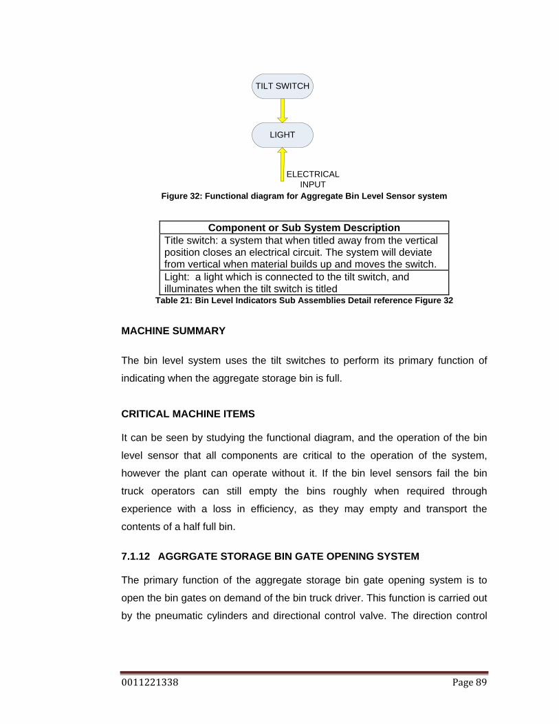
0011221338 Page 89
TILT SWITCH
LIGHT
ELECTRICALINPUT
Figure 32: Functional diagram for Aggregate Bin Level Sensor system
Component or Sub System Description Title switch: a system that when titled away from the vertical position closes an electrical circuit. The system will deviate from vertical when material builds up and moves the switch. Light: a light which is connected to the tilt switch, and illuminates when the tilt switch is titled
Table 21: Bin Level Indicators Sub Assemblies Detail reference Figure 32
MACHINE SUMMARY
The bin level system uses the tilt switches to perform its primary function of
indicating when the aggregate storage bin is full.
CRITICAL MACHINE ITEMS It can be seen by studying the functional diagram, and the operation of the bin
level sensor that all components are critical to the operation of the system,
however the plant can operate without it. If the bin level sensors fail the bin
truck operators can still empty the bins roughly when required through
experience with a loss in efficiency, as they may empty and transport the
contents of a half full bin.
7.1.12 AGGRGATE STORAGE BIN GATE OPENING SYSTEM The primary function of the aggregate storage bin gate opening system is to
open the bin gates on demand of the bin truck driver. This function is carried out
by the pneumatic cylinders and directional control valve. The direction control

0011221338 Page 90
valve is operated either by the manual override or the signal receiver. The
signal is sent from the transmitter. (B Fitzpatrick 2009, pers. comm., 02 June.)
PNEUMATIC CYLINDERS
DCV
SIGNAL TRANSMITTER
SIGNAL RECIEVER
MANUAL OPERATIONAL
SWITCH
CYLINDER MOUNTING
SYSTEM
ELECTRICALINPUT
AIR SYSTEM
Figure 33: Functional diagram for Aggregate Storage Bin Gate Opening system by
Author.
Component or Sub System Description Pneumatic cylinders: a bin gate system consists of 4 pneumatic cylinders. The cylinders open and close the clam gate system Cylinder mounting system: the pneumatic cylinder pivots at both ends of the cylinder. DCV: directional control valve, directs air to the desired cylinder. There is a DCV for each bin gate Air system: air supply from the air compressor Manual operational Switch: safety that allows for the bins to be emptied if the wireless system is non functional. Signal receiver: receives a particular signal, which is bin specific, and connects to the DCV for that particular bin. Signal transmitter: located in the bin truck, transmits a bin specific signal to the receiver.
Table 22: Aggregate Bin Gate Opening System Sub Assemblies Detail reference Figure 33

0011221338 Page 91
MACHINE SUMMARY
The bin gate opening system uses the pneumatic cylinders to perform its
primary function of opening the bin gates.
CRITICAL MACHINE ITEMS It can be seen by studying the functional diagram, and the operation of the
aggregate bin gate opening system, that all components are required for its
operation.
7.1.13 THE AGGREGATE BIN TRUCK
The primary function of the aggregate bin truck is transport aggregates from the
aggregate storage bins to the stock pile. The bin truck relies on a number of
systems to accomplish this which are beyond the scope of this dissertation.
Figure 34: Functional diagram for Bin Truck system by Author.
Component or Sub System Description
Bin truck: a rigid body tipping truck Table 23: Bin Truck Sub Assemblies Detail reference Figure 34
MACHINE SUMMARY
Serviceability of the bin truck systems is not permissible by onsite staff
CRITICAL MACHINE ITEMS It can be seen by studying the functional diagram, and the operation of the Bin
truck, and also following regulations, the entire bin truck is vital to the operation
of the plant.

0011221338 Page 92
7.1.14 DUST SUPPRESION SYSTEM The primary function of the dust suppression system is to reduce the amount of
airborne dust particles caused by the crushing and screening plant. This
function is primarily carried out by spray nozzles. Water is given flow by a water
pump, which pumps water from a storage tank to the desired location through
water pipes.
SPRAY NOZZLES
WATER PUMP SYSTEM
WATER STORAGE
TANK
ELECTRIC MOTOR
ELECTRICALINPUT
Figure 35: Functional Diagram For Dust Suppression System
Component or Sub System Description
Spray nozzles: spray nozzles of different spray types. Water pump system: consist of the water pump, water filter, and water pipes. Water storage tank: Electric motor: 5KW
Table 24: Dust Suppression Sub Assemblies Detail reference Figure 35
MACHINE SUMMARY
The dust suppression system uses water, spray nozzles and the water pump
system to perform its primary function of suppressing airborne dust particles.
CRITICAL MACHINE ITEMS It can be seen by studying the functional diagram, and the operation of the dust
suppression system, that all components are critical to the operation of the
system.
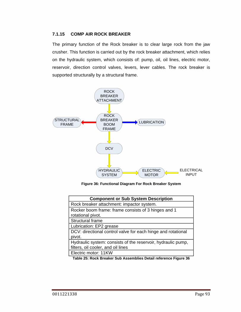
0011221338 Page 93
7.1.15 COMP AIR ROCK BREAKER The primary function of the Rock breaker is to clear large rock from the jaw
crusher. This function is carried out by the rock breaker attachment, which relies
on the hydraulic system, which consists of: pump, oil, oil lines, electric motor,
reservoir, direction control valves, levers, lever cables. The rock breaker is
supported structurally by a structural frame.
ROCK BREAKER
ATTACHMENT
ROCK BREAKER
BOOM FRAME
ELECTRIC MOTOR
ELECTRICALINPUT
DCV
HYDRAULIC SYSTEM
LUBRICATIONSTRUCTURAL FRAME
Figure 36: Functional Diagram For Rock Breaker System
Component or Sub System Description Rock breaker attachment: impactor system. Rocker boom frame: frame consists of 3 hinges and 1 rotational pivot. Structural frame Lubrication: EP2 grease DCV: directional control valve for each hinge and rotational pivot. Hydraulic system: consists of the reservoir, hydraulic pump, filters, oil cooler, and oil lines Electric motor: 11KW Table 25: Rock Breaker Sub Assemblies Detail reference Figure 36

0011221338 Page 94
MACHINE SUMMARY
The Comp Air Rock breaker system uses the rock breaker attachment to
perform its primary function of dislodging large rocks that have blocked the jaw
crusher.
CRITICAL MACHINE ITEMS It can be seen by studying the functional diagram, and the operation of the rock
breaker, that all components are critical to the operation of the system.
7.1.16 ATLAS COPCO AIR COMPRESSOR The primary function of the air compressor is to supply the plant with a constant
supply of air. The air compressor performs this function through many systems
that are beyond the scope of this dissertation.
Figure 37: Functional Diagram For Air Compressor System
Component or Sub System Description
Air compressor systems: supply the plant with a constant flow of air Table 26: Air Compressor Sub Assemblies Detail reference Figure 37
MACHINE SUMMARY
Serviceability of the air compressor systems is not permissible by onsite staff
CRITICAL MACHINE ITEMS It can be seen by studying the functional diagram, and the operation of the air
compressor that all components are required for its operation.

0011221338 Page 95
7.2 CHAPTER SUMMARY
The crushing and screening plant at Ormeau uses many different systems. The
systems have been broken down into smaller systems. The systems were
modeled using a top down approach to function diagrams. A complex system
that requires Original Equipment Manufacturers expertise to service is modeled
as a system comprising of many components, where a system that can be
serviced by onsite personnel is broken down into smaller systems. Some
systems used by the crushing and screening process can not be repaired by
untrained onsite staff for example: bin trucks, air compressor, and electrical
systems.
Critical items have been identified from the functional diagrams, and the
operation of the machines. This information will be vital in evaluating the effect
of failures in a machine to the overall outcome of the failure.

0011221338 Page 96
8. FMECA GORUND RULES
The FMECA process relies on engineering judgment to class and quantify
failure frequency occurrences, failure severities, and failure detection. For this
process to remain accurate and consistent there needs to be a standard.
8.1 FMECA STRUCTURE The FMECA will be structured to use the following categories:
1. Infrastructure
2. Sub system and Function
3. Failure Mode
4. Effect of Failure
5. Cause of Failure
6. Frequency Occurrence
7. Severity
8. Detection
9. Recommended Priority Number (RPN)
10. Recommendation
This structure covers the Failure Mode, Effect, and Criticality analysis. The
FMECA column breakdown originated from the IEC Standard 1985.
8.2 INFRASTRUCTURE
The column headed Infrastructure refers to the overall type of machine. The
FMECA for the Ormeau plant will be split up into the following Infrastructure
classifications:
1. Material Handling Conveyors
2. Crushing Equipment
3. Screening Equipment
4. Structure
5. Accessories
6. Electrical

0011221338 Page 97
All machines will fit into these 6 main Infrastructure classifications.
8.3 SUB SYSTEM The column headed Sub System refers to the sub systems which lie in the
Infrastructure category. The sub system is split into the following categories:
INFRASTRUCTURE SUB SYSTEM FAILURE MODE Material Handling
Conveyors
1. Material Handling
Conveyors
Crushing Equipment
1. Primary Jaw Crusher
2. Secondary and
Tertiary Cone
crushers
3. Quaternary Crusher
VSI
Screening Equipment 1. Screen
Structure
1. Bins
2. Chutes
3. Transfer Points
4. Structural Steel
5. Dust Suppression
6. Bin Gate Opening
System
Accessories 1. Rock Breaker
Electrical 1. Motor Control
2. Bin Level System
Table 27: First three columns of the FMECA
8.4 FAILURE MODE
The failure mode column uses the functional diagrams and engineering
judgment to detail failure modes. The functional diagrams are used to identify
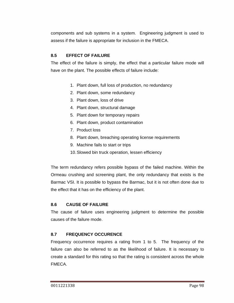
0011221338 Page 98
components and sub systems in a system. Engineering judgment is used to
assess if the failure is appropriate for inclusion in the FMECA.
8.5 EFFECT OF FAILURE The effect of the failure is simply, the effect that a particular failure mode will
have on the plant. The possible effects of failure include:
1. Plant down, full loss of production, no redundancy
2. Plant down, some redundancy
3. Plant down, loss of drive
4. Plant down, structural damage
5. Plant down for temporary repairs
6. Plant down, product contamination
7. Product loss
8. Plant down, breaching operating license requirements
9. Machine fails to start or trips
10. Slowed bin truck operation, lessen efficiency
The term redundancy refers possible bypass of the failed machine. Within the
Ormeau crushing and screening plant, the only redundancy that exists is the
Barmac VSI. It is possible to bypass the Barmac, but it is not often done due to
the effect that it has on the efficiency of the plant.
8.6 CAUSE OF FAILURE The cause of failure uses engineering judgment to determine the possible
causes of the failure mode.
8.7 FREQUENCY OCCURENCE Frequency occurrence requires a rating from 1 to 5. The frequency of the
failure can also be referred to as the likelihood of failure. It is necessary to
create a standard for this rating so that the rating is consistent across the whole
FMECA.

0011221338 Page 99
It is also necessary to use a time frame for the evaluation of the frequency of
failure. Since the Quarry Reporting System (QRS) uses monthly data reviews
and production targets. It is convenient to use the same time frame. Therefore
the frequency of failure will be judged using a 1 month time frame.
RATING DESCRIPTION FREQUENCY
5 Almost certain A failure is expected to occur in most circumstances. Once a month or more frequently.
4 Likely A failure will probably occur in most circumstances. Once every 3 months
3 Possible A failure might occur at sometime. Once every 6 months
2 Unlikely A failure could occur at some time Once every 9 months
1 Rare A failure may occur in exceptional circumstances. Once a year.
Table 28: Frequency value itemisation by Author.
8.8 SEVERITY The severity of the failure requires a rating of 1 to 5. The severity of the failure is
related to the effect of the failure. It is necessary to create a standard for rating
these criteria.
RATING DESCRIPTION SEVERITY 5 Catastrophic Plant down, all production lost
4 Major Plant down, redundancies used, 50% loss of production
3 Border 50% loss of production output, inefficient to run, therefore plant down.
2 Moderate 25% loss of production output. 1 Minor 10% loss of production output
Table 29: Severity value itemisation by Author.

0011221338 Page 100
8.9 DETECTION The detection value also requires a rating of 1 to 5. The detection refers to the
ability to detect a particular failure. It is a rating of how detectable a failure is.
RATING DESCRIPTION DECTECTION 5 No detection Fault is not detectable 4 Detection Fault is detectable through experience. 3 Inspection Fault is detectable through visual inspection
2 Operator Detection
Operator can detect the fault through an audio monitoring
1 Detectable Fault is detectable through a protection system Table 30: Severity value itemisation by Author.
8.10 RPN The RPN is the Recommended Priority Number. The RPN can range from 1 to
125. The RPN serves as the criticality analysis. The RPN is the product of the
frequency, severity and detection values. A Fault with a higher RPN is more
critical. A high RPN will mean that a fault has a high frequency, high severity
and is not detectable; this particular failure will require high action.
8.11 RECOMMENDATION
Engineering judgment based on experience is used to make a recommendation
about each fault. The recommendation serves to reduce all assessment item
values: frequency, severity and detection.
8.12 CHAPTER SUMMARY
The FMECA structure has been detailed, and each item in the structure has
been described and defined. To keep the FMECA consistent the evaluation
values of Frequency, Severity, and Detection have been summarised. The RPN
has been defined and a description of how it is calculated has been given. The
recommendation gives a small recommendation of how the failure can be
reduced.

0011221338 Page 101
9. PLANT FMECA
Infrastructure Sub System
Subsystem Function
Failure Mode
Effect of Failure
Cause of Failure Frequency O
ccurrenc
Severity
Detection
RPN
Recommendation
Material handling - conveyors
Conveyor aggregates through the process. All production stopped.
Mechanical damage to belting
Spillage, belt torn. Plant down - until belt repaired or replaced.
1. Poor housekeeping 2. Rock caught in
structure or scraper 3. Roller failure 4. Skirt failure 5. Wear plate/ liner
failure 6. Scraper failure 7. Fatigue 8. Poor splice / splice
failure. 9. Overload 10. Bearing failure
5 4
3 4 3
4 2 4
3
4
3 4
2 2 3
3 4 4
4
4
1 2
3 3 3
2 4 2
2
3
15 32
18 24 27
24 32 32
24
48
Operator supervision Limit switches on belt weighers. Routine inspections Routine inspections Routine maintenance program Routine inspection program Routine maintenance program Determine belt replacement interval Routine maintenance
Motor Failure Loss Of Drive Plant Down
1. Bearing Failure 2. Fatigue 3. Overload 4. Water Entry 5. Over Temp
4 2 2
3 3
4 4 3
4 2
3 4 2
4 2
48 32 12
48 12
Critical spares. Run to failure Limit switches on belt weighers Thermal overloads on motors
Gearbox Failure
Loss Of Drive Plant Down
1. Bearing Failure 2. Lubrication Failure 3. Fatigue 4. Overload 5. Over Temp
4
4 3 2 2
4
4 4 3 3
3
2 4 4 3
48
32 48 24 18
Standardise box configuration and ratio; critical spare Routine maintenance Limit switch on belt weigher Thermocouples

0011221338 Page 102
Infrastructure Sub System
Subsystem Function
Failure Mode
Effect of Failure
Cause of Failure Frequency O
ccurrenc
Severity
Detection
RPN
Recommendation
V-Belt Drive Failure
Loss Of Drive Plant Down
1. Misalignment 2. Contamination 3. Fatigue 4. Overload
4 3 3 3
3 2 3 3
2 2 3 4
24 12 27 36
Routine inspection Routine inspection of guards Critical spare
Pulley / Roller / Drum Failure
Loss Of Drive Structural Damage
1. Fatigue / Age 2. Mechanical
Damage 3. Poor Design /
Quality
2 3 2
4 4 3
4 4 3
32 48 18
Critical Spare Housekeeping
Crushing equipment
Primary jaw Reduce input rock size
Structural failure
Machine down. No redundancy so full loss of production.
1. Fatigue 2. Poor maintenance 3. Overload 4. Contamination1
2 3 3 3
5 4 3 3
4 2 2 3
40 24 18 27
Routine inspection program Routine maintenance Chute to restrict top size Operator supervision
Liner Failure Machine Down / Plant Down
1. Worn Out 2. Mounting
Connection Failure 3. Contamination 4. Loss Of Stroke
4 3
3 4
3 4
4 3
1 3
3 1
12 36
36 12
Routine inspection Maintenance Supervision Operator Supervision Routine inspection
1 All crushers are effected by materials that have a higher tensile strength than rock, such as ground engaging tools, wear materials and some thermal modified source rock. Most crushers are protected by metal detectors or magnets.
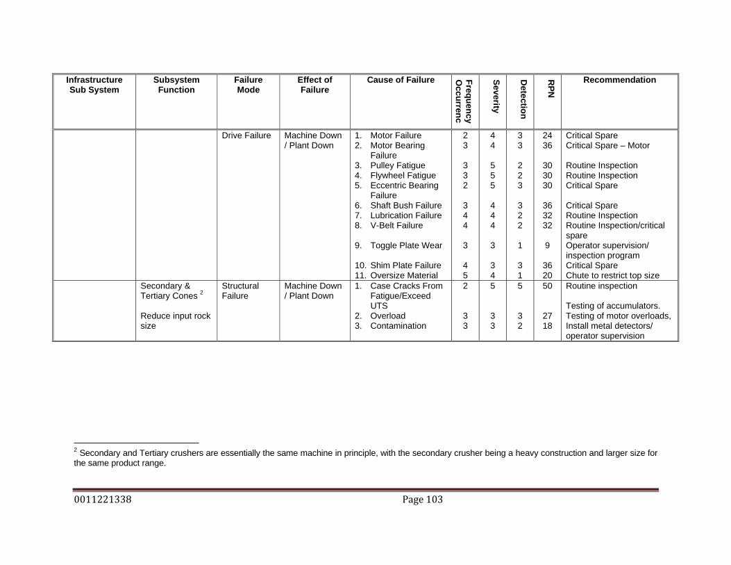
0011221338 Page 103
Infrastructure Sub System
Subsystem Function
Failure Mode
Effect of Failure
Cause of Failure Frequency O
ccurrenc
Severity
Detection
RPN
Recommendation
Drive Failure Machine Down / Plant Down
1. Motor Failure 2. Motor Bearing
Failure 3. Pulley Fatigue 4. Flywheel Fatigue 5. Eccentric Bearing
Failure 6. Shaft Bush Failure 7. Lubrication Failure 8. V-Belt Failure 9. Toggle Plate Wear 10. Shim Plate Failure 11. Oversize Material
2 3
3 3 2
3 4 4
3
4 5
4 4
5 5 5
4 4 4
3
3 4
3 3
2 2 3
3 2 2
1
3 1
24 36
30 30 30
36 32 32
9
36 20
Critical Spare Critical Spare – Motor Routine Inspection Routine Inspection Critical Spare Critical Spare Routine Inspection Routine Inspection/critical spare Operator supervision/ inspection program Critical Spare Chute to restrict top size
Secondary & Tertiary Cones 2 Reduce input rock size
Structural Failure
Machine Down / Plant Down
1. Case Cracks From Fatigue/Exceed UTS
2. Overload 3. Contamination
2
3 3
5
3 3
5
3 2
50
27 18
Routine inspection Testing of accumulators. Testing of motor overloads, Install metal detectors/ operator supervision
2 Secondary and Tertiary crushers are essentially the same machine in principle, with the secondary crusher being a heavy construction and larger size for the same product range.
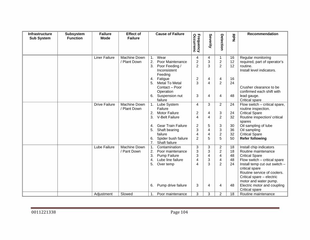
0011221338 Page 104
Infrastructure Sub System
Subsystem Function
Failure Mode
Effect of Failure
Cause of Failure Frequency O
ccurrenc
Severity
Detection
RPN
Recommendation
Liner Failure Machine Down / Plant Down
1. Wear 2. Poor Maintenance 3. Poor Feeding /
Inconsistent Feeding
4. Fatigue 5. Metal To Metal
Contact – Poor Operation
6. Suspension nut failure
4 2 2
2 3
3
4 3 3
4 4
4
1 2 2
4 2
4
16 12 12
16 24
48
Regular monitoring required, part of operator’s routine. Install level indicators. Crusher clearance to be confirmed each shift with lead gauge. Critical spare
Drive Failure Machine Down / Plant Down
1. Lube System Failure
2. Motor Failure 3. V-Belt Failure 4. Gear Train Failure 5. Shaft bearing
failure 6. Spider bush failure 7. Shaft failure
4
2 4
2 3 4 2
3
4 4
5 4 4 5
2
3 2
3 3 2 5
24
24 32
30 36 32 50
Flow switch – critical spare, routine inspection. Critical Spare Routine inspection/ critical spares Oil sampling of lube Oil sampling Critical Spare Refer following
Lube Failure Machine Down / Pant Down
1. Contamination 2. Poor maintenance 3. Pump Failure 4. Lube line failure 5. Over temp 6. Pump drive failure
3 3 3 4 4
3
3 3 4 3 3
4
2 2 4 4 2
4
18 18 48 48 24
48
Install chip indicators Routine maintenance Critical Spare Flow switch – critical spare Install temp cut out switch – critical spare Routine service of coolers. Critical spare – electric motor and water pump. Electric motor and coupling Critical spare
Adjustment Slowed 1. Poor maintenance 3 3 2 18 Routine maintenance

0011221338 Page 105
Infrastructure Sub System
Subsystem Function
Failure Mode
Effect of Failure
Cause of Failure Frequency O
ccurrenc
Severity
Detection
RPN
Recommendation
failure (Omnicone)
Production 2. Pump failure 3. Tramp cylinder leak 4. Adjustment cylinder
failure 5. DCV failure
3 3 2
2
3 4 2
2
4 2 2
3
36 24 8
12
Critical spare Critical spare Inspection program Critical spare
Quaternary Crusher (VSI) Reduce input rock size
Rotor Failure Machine Down / Plant Down
1. Wear 2. Imbalance from wet
materials poor operation
3. Poor maintenance 4. Oversize material
4 3
3 5
4 3
3 3
2 4
3 2
32 36
27 30
Routine Inspections Routine Inspections / routine maintenance on wear plates Maintenance supervision Routine inspections of
Drive Failure Machine Down / Plant Down
1. Motor Failure 2. Bearing Cartridge
Failure 3. Pulley Failure 4. V-Belt Failure
2 4
2 3 4
4 4
4 3 3
4 4
3 2 2
32 64
24 18 24
Critical Spare Critical Spare - Vibration sensor Routine Inspection Routine Inspection
Housing Failure
Outage to reline – temporary repair usually possible
1. Poor Maintenance 2. Poor operation 3. Failure of feed
screen leading to oversize.
3 2 4
3 3 3
2 2 2
18 12 24
Routine Inspection Operator supervision Routine inspection of leading screens
Screening Plant Screen Separate material by size
Media Failure Temporary repairs until downtime to replace
1. Poor Operation 2. Run to failure 3. Contamination 4. Poor fitment 5. Overload
3 3 4 4 3
3 2 3 3 2
2 2 2 3 2
18 12 24 36 12
Operation supervision Routine inspections Clean screens – pegging Supervision / skills issue Operator surveillance

0011221338 Page 106
Infrastructure Sub System
Subsystem Function
Failure Mode
Effect of Failure
Cause of Failure Frequency O
ccurrenc
Severity
Detection
RPN
Recommendation
Deck Failure Machine Down / Plant Down, Product contamination leading to devalued product
1. Fatigue 2. Overload 3. Excess vibration
due to eccentric fault
4. Poor media fitment 5. Wear 6. Poor maintenance
3 2 3
4 5 3
4 2 4
3 4 4
3 2 2
2 2 2
36 8 24
24 40 24
Routine inspection Operator surveillance Vibration sensor – peak exceed Maintenance Supervision Routine inspection Routine maintenance
Mechanism Failure / Drive Failure
Machine Down / potential Consequential damage
1. Fatigue 2. Bearing Failure 3. Imbalance due to
weight coming off 4. Shaft Failure due to
vibration 5. V-belt loss 6. Motor failure
3 3
3
2
4 2
4 4
3
4
3 4
4 3
4
2
4 4
48 36
36
16
36 32
Critical Spare Oil sampling, vibration analysis.. Peak Vibration Sensor Peak Vibration Sensor Critical spare. Critical spare.
Structure Bins Hold material
Function failure
Product Loss 1. Poor maintenance 2. Poor Attachment 3. Excessive Vibration 4. Poor Design 5. Overloading 6. Excessive wear
plate wear
3 4 2 2 3
3
3 3 3 3 3
2
2 4 2 2 4
2
18 48 12 12 36
12
Routine maintenance Maintenance supervision. Engineering involvement Adequate support Engineering involvement Limit chutes to discharge overload Maintenance program / inspection program
Chutes Deliver material
Function Failure
Product Loss / Contamination
1. Poor Maintenance 2. Poor Design 3. Excessive Vibration 4. Material build up 5. Blockage 6. Excessive wear
4
4 3 5 4 3
3
3 3 3 3 2
2
2 2 3 4 2
24
24 18 45 48 12
Routine maintenance Engineering involvement Adequate support Limit switch in prone areas Limit switch in prone areas Routine maintenance /

0011221338 Page 107
Infrastructure Sub System
Subsystem Function
Failure Mode
Effect of Failure
Cause of Failure Frequency O
ccurrenc
Severity
Detection
RPN
Recommendation
plate wear inspection program Transfer points
Deliver material
Function failure
Product Loss / Contamination
1. Poor Maintenance 2. Side skirt condition 3. Poor Design 4. Excessive Vibration 5. Material build up 6. Blockage 7. Excessive wear
plate wear
4 3
4 3 5 4 3
3 2
3 3 3 3 2
2 2
2 2 3 4 2
24 12
24 18 45 48 12
Routine maintenance Routine inspection program / critical spare Engineering involvement Adequate support Limit switch in prone areas Limit switch in prone areas Routine maintenance / inspection program
Structural Steel Support plant machines and processes
Failure Plant Down 1. Connection Failure 2. Design fault 3. Overload 4. Change in
Operation 5. Poor Housekeeping 6. Poor Maintenance 7. Fire
2 2 3 4
5 4 1
5 5 5 4
4 4 5
4 4 2 2
1 1 4
40 40 30 32
20 16 20
Routine inspection program Engineer Engineering Involvement Belt weighers Supervision Supervision Suitable response equipment
Dust Suppression Reduce airborne dust particles
Failure Loss of dust control breaching operating license requirements. Plant down
1. Storage tank level 2. Pump system
failure
3. Water line failure
3 1
2
5 5
4
2 2
2
30 10
16
Routine inspection program, Routine inspection/ maintenance program / critical spare Routine inspection program / critical spare
Bin Gate Opening System Open bin gates when desired
Wireless System
Slowed bin truck operation / slowed production
1. Poor power connections
2. Poor transmitter condition
3. Poor receiver condition
3
3
3
2
2
2
5
5
5
30
30
30
Routine maintenance program Routine inspection program Routine inspection program
Actuation Plant down 1. Cylinder failure 2 5 3 30 Routine inspection program
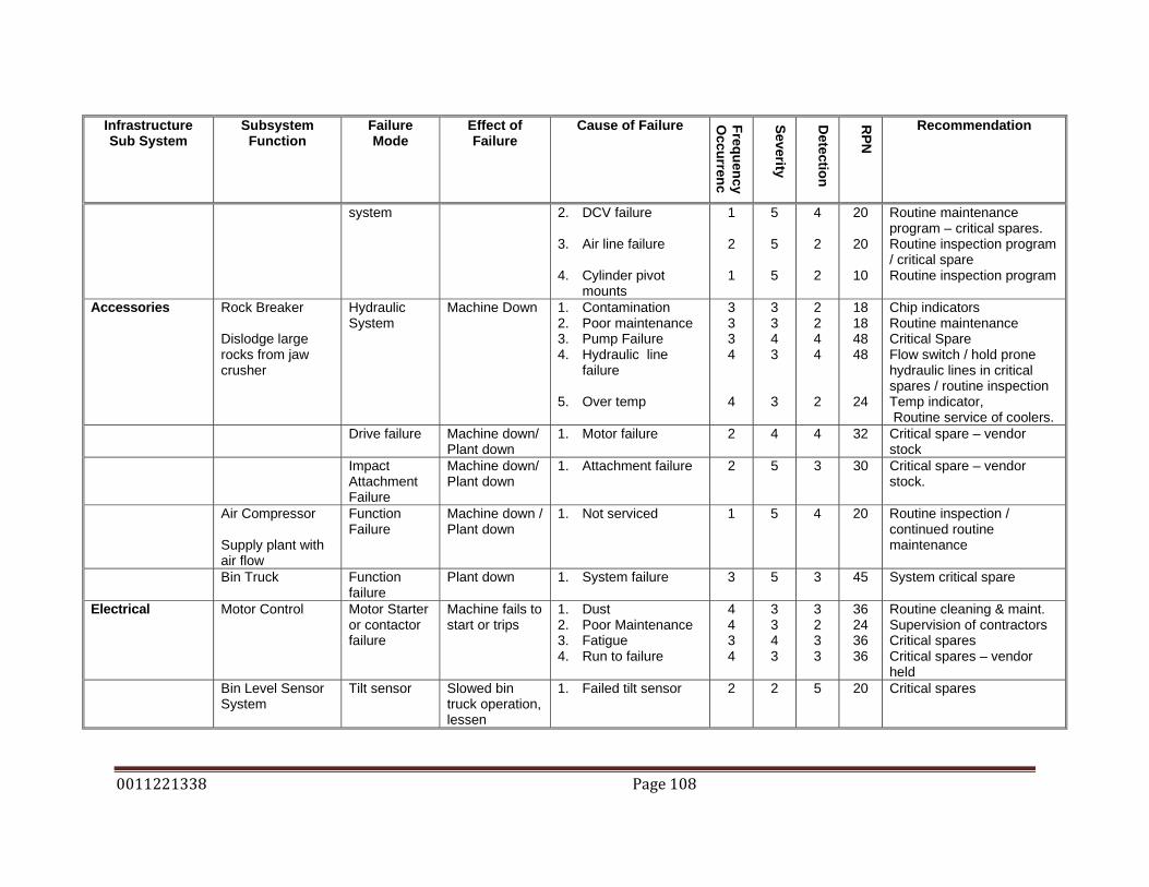
0011221338 Page 108
Infrastructure Sub System
Subsystem Function
Failure Mode
Effect of Failure
Cause of Failure Frequency O
ccurrenc
Severity
Detection
RPN
Recommendation
system 2. DCV failure 3. Air line failure 4. Cylinder pivot
mounts
1
2
1
5
5
5
4
2
2
20
20
10
Routine maintenance program – critical spares. Routine inspection program / critical spare Routine inspection program
Accessories Rock Breaker Dislodge large rocks from jaw crusher
Hydraulic System
Machine Down 1. Contamination 2. Poor maintenance 3. Pump Failure 4. Hydraulic line
failure 5. Over temp
3 3 3 4
4
3 3 4 3
3
2 2 4 4
2
18 18 48 48
24
Chip indicators Routine maintenance Critical Spare Flow switch / hold prone hydraulic lines in critical spares / routine inspection Temp indicator, Routine service of coolers.
Drive failure Machine down/ Plant down
1. Motor failure 2 4 4 32 Critical spare – vendor stock
Impact Attachment Failure
Machine down/ Plant down
1. Attachment failure 2 5 3 30 Critical spare – vendor stock.
Air Compressor Supply plant with air flow
Function Failure
Machine down / Plant down
1. Not serviced 1 5 4 20 Routine inspection / continued routine maintenance
Bin Truck Function failure
Plant down 1. System failure 3 5 3 45 System critical spare
Electrical Motor Control Motor Starter or contactor failure
Machine fails to start or trips
1. Dust 2. Poor Maintenance 3. Fatigue 4. Run to failure
4 4 3 4
3 3 4 3
3 2 3 3
36 24 36 36
Routine cleaning & maint. Supervision of contractors Critical spares Critical spares – vendor held
Bin Level Sensor System
Tilt sensor Slowed bin truck operation, lessen
1. Failed tilt sensor 2 2 5 20 Critical spares

0011221338 Page 109
Infrastructure Sub System
Subsystem Function
Failure Mode
Effect of Failure
Cause of Failure Frequency O
ccurrenc
Severity
Detection
RPN
Recommendation
Indicate when aggregate levels are high inside bins
efficiency
Indicator light Slowed bin truck operation, lessen efficiency
1. Failed light bulb 2 1 5 10 Critical spares

0011221338 Page 110
10. RECOMMENDATIONS Recommendations have been made to try to reduce the frequency, severity and
detection values, which are combined to give the RPN, of failure modes based
on the FMECA. It is necessary to further develop the recommendations for each
machine that has been considered, which include:
• 1 Pegson jaw crusher, 1100mm x 850mm, as the primary crusher
• 1 900mm Jaques gyratory cone crusher in a secondary configuration
• 1 Nordberg Omnicone gyratory crusher as the tertiary crusher
• 1 Barmac Rotopactor Vertical Shaft Impact crusher (VSI) as the
quaternary crusher
• 8 Malco 2.4m x 1.2m vibrating screens
• 11 material handling conveyors of different sizes
• Material handling transfer points
• Material handling chutes.
• 16 aggregate storage bins
• Surge bin
• Aggregate bin level sensors.
• Aggregate bin gate opening system
• Aggregate bin truck
• Dust suppression system
• Comp Air hydraulic rock breaker.
• 1 Atlas Copco air compressor.
• Structural framing
• Electrical
10.1 JAW CRUSHER From the FMECA conducted on the Pegson Jaw Crusher: inspection programs,
critical spares, operator supervision programs, maintenance supervision
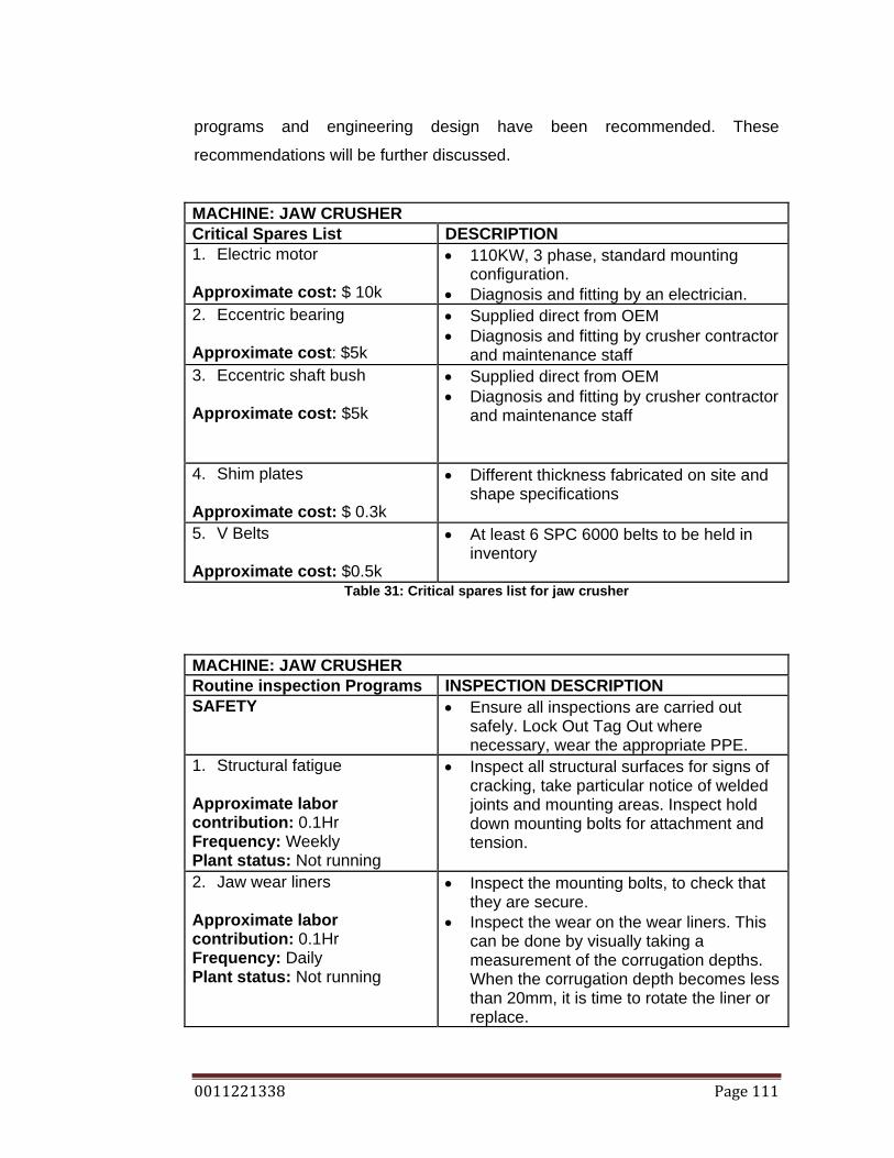
0011221338 Page 111
programs and engineering design have been recommended. These
recommendations will be further discussed.
MACHINE: JAW CRUSHER Critical Spares List DESCRIPTION 1. Electric motor Approximate cost: $ 10k
• 110KW, 3 phase, standard mounting configuration.
• Diagnosis and fitting by an electrician. 2. Eccentric bearing Approximate cost: $5k
• Supplied direct from OEM • Diagnosis and fitting by crusher contractor
and maintenance staff 3. Eccentric shaft bush Approximate cost: $5k
• Supplied direct from OEM • Diagnosis and fitting by crusher contractor
and maintenance staff
4. Shim plates Approximate cost: $ 0.3k
• Different thickness fabricated on site and shape specifications
5. V Belts Approximate cost: $0.5k
• At least 6 SPC 6000 belts to be held in inventory
Table 31: Critical spares list for jaw crusher
MACHINE: JAW CRUSHER Routine inspection Programs INSPECTION DESCRIPTION SAFETY • Ensure all inspections are carried out
safely. Lock Out Tag Out where necessary, wear the appropriate PPE.
1. Structural fatigue Approximate labor contribution: 0.1Hr Frequency: Weekly Plant status: Not running
• Inspect all structural surfaces for signs of cracking, take particular notice of welded joints and mounting areas. Inspect hold down mounting bolts for attachment and tension.
2. Jaw wear liners Approximate labor contribution: 0.1Hr Frequency: Daily Plant status: Not running
• Inspect the mounting bolts, to check that they are secure.
• Inspect the wear on the wear liners. This can be done by visually taking a measurement of the corrugation depths. When the corrugation depth becomes less than 20mm, it is time to rotate the liner or replace.

0011221338 Page 112
3. Loss of swing jaw stroke Approximate labor contribution: 0.1Hr Frequency: Daily Plant status: Running
• Check that the crusher still has adjustment available. If crusher is at the end of the its adjustment, it is time to change or rotate either, or both jaw liners.
4. Pulley fatigue Approximate labor contribution: 0.1Hr Frequency: Daily Plant status: Not running
• Inspect the pulley, taking particular notice of the spokes, for cracks.
• Inspect the clamping bolts for tension • Check that the end of shaft cap bolts are
securely mounted.
5. Flywheel fatigue See Pulley fatigue Inspection 6. Lubrication failure Approximate labor contribution: 0.1Hr Frequency: Daily Plant status: Not running
• Inspect all grease lines for deterioration, holes, and wear marks.
• Inspect all grease nipples, check that they hold grease.
• Ensure greasing is occurring daily, when the crusher is warm and running
7. V belt wear/condition/tension Approximate labor contribution: 0.1Hr Frequency: Daily Plant status: Not running
• Inspect the V belts, ensure that they are all still present, inspect the underside for cracks, and check the belt tension by pushing on the belt between the longest span of the belt, there should be no more than 20mm of movement in the belt.
Table 32: Routine inspection program for jaw crusher
MACHINE: JAW CRUSHER Maintenance Supervision DESCRIPTION SAFETY • Ensure all inspections are carried out
safely. Lock Out Tag Out where necessary, wear the appropriate PPE.
1. Wear liner mounting bolt fitment
Approximate labor contribution: 1Hr Frequency: After liner replacement or rotation Plant status: Not running
• Ensure that workers don’t only use an air impact gun to secure the bolts, they must be tightened to a final torque by using a hammer impact.
• Ensure that the threads of the bolt, and under the mounting side of the nut are lubricated to overcome some of the friction.
• Ensure safe practices. Table 33: Maintenance supervision program for jaw crusher

0011221338 Page 113
MACHINE: JAW CRUSHER Operator Supervision DESCRIPTION SAFETY • Ensure all inspections and operations are
carried out safely. Lock Out Tag Out where necessary, wear the appropriate PPE.
Ensure that no metallic objects are feed into the plant Frequency: Constantly
• Ensure that front end loader operators create working piles, so that where possible metallic objects maybe identified and isolated.
• Inform operators to constant check that all bucket ground engaging tools attached, and have not been feed into the plant.
Ensure that the plant operator is constantly conducting audio tests Frequency: Daily Plant status: Running
• Train the plant operator to listen to the jaw and to constant monitor the sound of the toggle plate. By listening to the sound that the jaw is making can give a good indication of the toggle seats. A worn toggle seat will have a definite knock on each stroke.
Table 34: Operator supervision program for jaw crusher
MACHINE: JAW CRUSHER Installation list Design Brief To design the feed chute to restrict the input rock size
• The chute would need to be strong enough to take large impacts of rocks rolling down the live tipping bin.
• It would need to be able to restrict the input rock size but, to still allow smaller rocks through, while the larger rock was removed.
Table 35: Installation list for jaw crusher

0011221338 Page 114
10.2 900MM JAQUES GYRATORY CONE CRUSHER From the FMECA conducted on the 900mm Jaques Cone Crusher the
recommendations include: Routine testing programs, routine monitoring
programs, critical spares, routine maintenance programs, installations and
maintenance supervision programs.
MACHINE: JAQUES CONE CRUSHER Critical Spares List DESCRIPTION 1. Electric motor Approximate cost: $ 10k
• 110KW, 3 phase, standard mounting configuration.
• Diagnosis and fitting by an electrician. 2. Oil flow switch Approximate cost: $1k
• Supplied direct from Electrician • Diagnosis and fitting by electrician
3. Oil temperature switch Approximate cost: $1k
• Supplied direct from Electrician • Diagnosis and fitting by electrician
4. Spider bush Approximate cost: $3k
• Supplied direct from OEM • Diagnosis and fitting by crusher contractor
and maintenance staff 5. Lube pump Approximate cost: $ 2k
• Supplied direct from OEM • Diagnosis and fitting by crusher contractor
and maintenance staff 6. V Belts Approximate cost: $0.5k
• At least 6 SPC 6000 belts to be held in inventory
7. Suspension nut assembly Approximate cost: $5k
• Supplied direct from OEM • Diagnosis and fitting by crusher contractor
and maintenance staff 8. Lube electric motor and
coupling Approximate cost: $2k
• Supplied direct from Electrician • Diagnosis and fitting by electrician
9. Water pump and electric motor
Approximate cost: $3k
• Supplied direct from Electrician • Diagnosis and fitting by electrician
10. Lube oil Approximate cost: $2k
• 220W gear oil
Table 36: Critical spares list for Jaques cone crusher
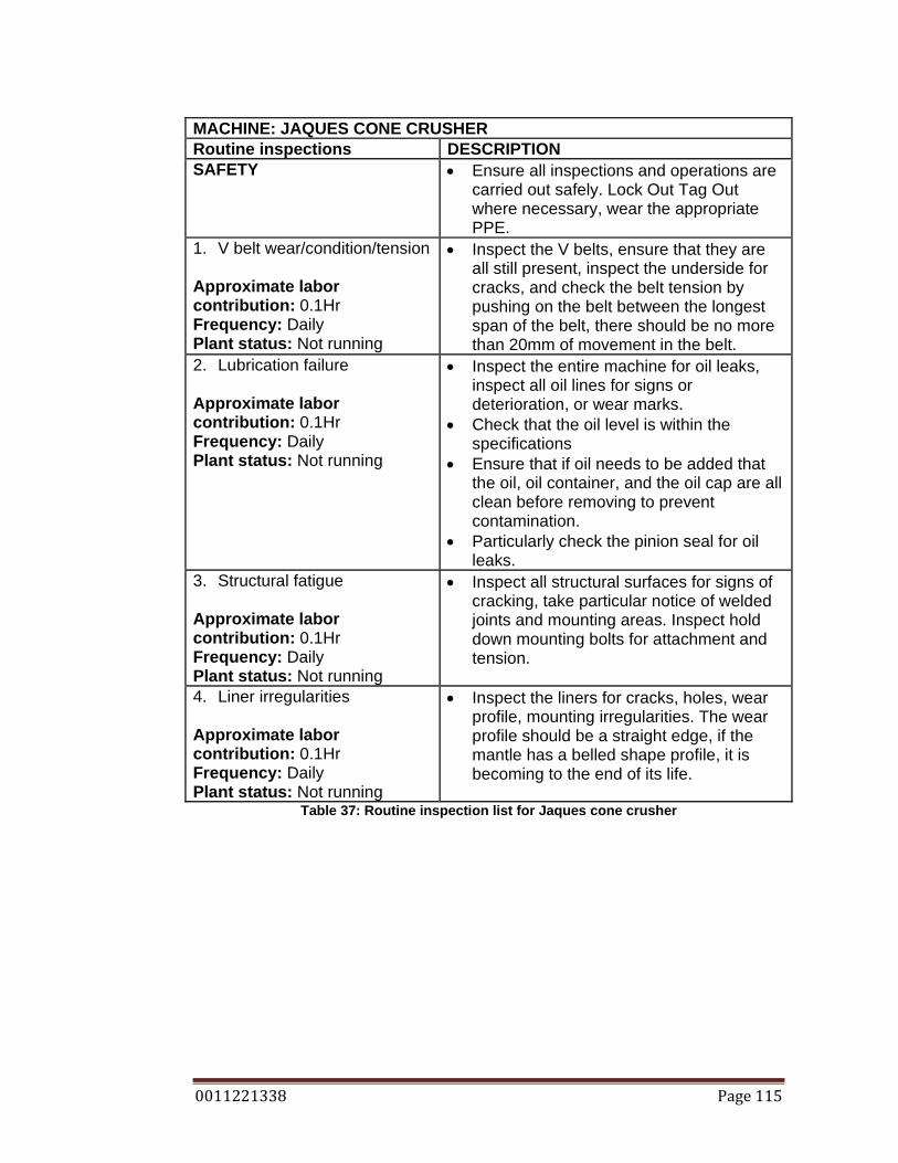
0011221338 Page 115
MACHINE: JAQUES CONE CRUSHER Routine inspections DESCRIPTION SAFETY • Ensure all inspections and operations are
carried out safely. Lock Out Tag Out where necessary, wear the appropriate PPE.
1. V belt wear/condition/tension Approximate labor contribution: 0.1Hr Frequency: Daily Plant status: Not running
• Inspect the V belts, ensure that they are all still present, inspect the underside for cracks, and check the belt tension by pushing on the belt between the longest span of the belt, there should be no more than 20mm of movement in the belt.
2. Lubrication failure Approximate labor contribution: 0.1Hr Frequency: Daily Plant status: Not running
• Inspect the entire machine for oil leaks, inspect all oil lines for signs or deterioration, or wear marks.
• Check that the oil level is within the specifications
• Ensure that if oil needs to be added that the oil, oil container, and the oil cap are all clean before removing to prevent contamination.
• Particularly check the pinion seal for oil leaks.
3. Structural fatigue Approximate labor contribution: 0.1Hr Frequency: Daily Plant status: Not running
• Inspect all structural surfaces for signs of cracking, take particular notice of welded joints and mounting areas. Inspect hold down mounting bolts for attachment and tension.
4. Liner irregularities Approximate labor contribution: 0.1Hr Frequency: Daily Plant status: Not running
• Inspect the liners for cracks, holes, wear profile, mounting irregularities. The wear profile should be a straight edge, if the mantle has a belled shape profile, it is becoming to the end of its life.
Table 37: Routine inspection list for Jaques cone crusher

0011221338 Page 116
MACHINE: JAQUES CONE CRUSHER Routine monitoring DESCRIPTION SAFETY • Ensure all inspections are carried out
safely. Lock Out Tag Out where necessary, wear the appropriate PPE.
1. CSS measurement
Approximate labor contribution: 0.10Hr Frequency: Weekly Plant status: Running
• Measure the CSS, this can be done by lowering a lead gauge into the crushing chamber, removing, and measuring the width of the crushed lead. The thickness indicates the CSS and also a comparison with the previous weeks CSS will indicate the wear rate.
2. Pinion bearing temperature Approximate labor contribution: 0.10Hr Frequency: Weekly Plant status: Running
• Use a thermo gun to check the temperature of the pinion housing. Compare the temperature with the last and reading and consider the ambient temperature. If it is running above 80 degrees Celsius there may be a problem.
Table 38: Routine monitoring list for Jaques cone crusher
MACHINE: JAQUES CONE CRUSHER Routine testing DESCRIPTION SAFETY • Ensure all inspections are carried out
safely. Lock Out Tag Out where necessary, wear the appropriate PPE.
1. Motor overload settings Approximate cost contribution: $2k Frequency: Yearly
• Undertaken by an electrician
2. Oil sample testing Approximate cost contribution: $0.2k Frequency: Quarterly
• Oil sampling between oil changes, particularly test the metal content.
Table 39: Routine testing list for Jaques cone crusher

0011221338 Page 117
MACHINE: JAQUES CONE CRUSHER Installation list DESCRIPTION 1. Temperature cut out switch Approximate cost contribution: $2k
• Install a temperature switch to only work between the 16 to 70 degrees Celsius, which would be the same switch as the Omnicone – standardizing parts.
2. Metal detectors Approximate cost contribution: $5k
• Fit a metal detector on the crusher feed conveyor, which will shut the conveyor and all components behind, until the metallic object can be cleared to restart.
3. Chip indictors Approximate cost contribution: $2k
• Install chip indicator in the oil system, for early detection internal components before further damage results.
Table 40: Installation list for Jaques cone crusher
MACHINE: JAQUES CONE CRUSHER Operator supervision DESCRIPTION Ensure that no metallic objects are feed into the plant Frequency: Constantly
• See Jaw Crusher Operator supervision
Table 41: Operator supervision list for Jaques cone crusher (By Author)
MACHINE: JAQUES CONE CRUSHER Routine maintenance DESCRIPTION Oil cooler servicing Frequency: yearly, before summer
• Remove oil cooler and clean professionally.
Oil/filter changes Frequency: every 1000 crushing hours.
• Change the oil every 1000hrs, or when it starts to discolor. 1000 hrs oil changes is based on staff experience.
Table 42: Routine maintenance list for Jaques cone crusher (By Author)
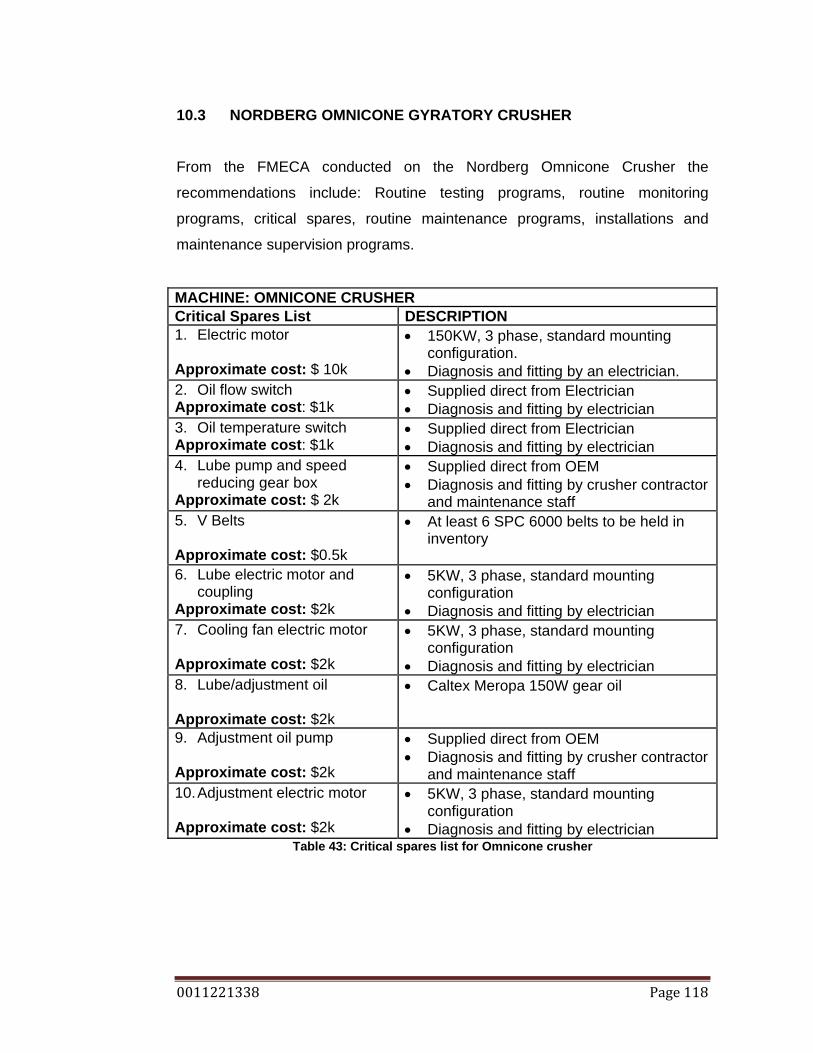
0011221338 Page 118
10.3 NORDBERG OMNICONE GYRATORY CRUSHER From the FMECA conducted on the Nordberg Omnicone Crusher the
recommendations include: Routine testing programs, routine monitoring
programs, critical spares, routine maintenance programs, installations and
maintenance supervision programs.
MACHINE: OMNICONE CRUSHER Critical Spares List DESCRIPTION 1. Electric motor Approximate cost: $ 10k
• 150KW, 3 phase, standard mounting configuration.
• Diagnosis and fitting by an electrician. 2. Oil flow switch Approximate cost: $1k
• Supplied direct from Electrician • Diagnosis and fitting by electrician
3. Oil temperature switch Approximate cost: $1k
• Supplied direct from Electrician • Diagnosis and fitting by electrician
4. Lube pump and speed reducing gear box
Approximate cost: $ 2k
• Supplied direct from OEM • Diagnosis and fitting by crusher contractor
and maintenance staff 5. V Belts Approximate cost: $0.5k
• At least 6 SPC 6000 belts to be held in inventory
6. Lube electric motor and
coupling Approximate cost: $2k
• 5KW, 3 phase, standard mounting configuration
• Diagnosis and fitting by electrician 7. Cooling fan electric motor
Approximate cost: $2k
• 5KW, 3 phase, standard mounting configuration
• Diagnosis and fitting by electrician 8. Lube/adjustment oil Approximate cost: $2k
• Caltex Meropa 150W gear oil
9. Adjustment oil pump Approximate cost: $2k
• Supplied direct from OEM • Diagnosis and fitting by crusher contractor
and maintenance staff 10. Adjustment electric motor Approximate cost: $2k
• 5KW, 3 phase, standard mounting configuration
• Diagnosis and fitting by electrician Table 43: Critical spares list for Omnicone crusher

0011221338 Page 119
MACHINE: OMNICONE CRUSHER Routine inspections DESCRIPTION SAFETY • Ensure all inspections and operations are
carried out safely. Lock Out Tag Out where necessary, wear the appropriate PPE.
1. V belt wear/condition/tension Approximate labor contribution: 0.1Hr Frequency: Daily Plant status: Not running
• Inspect the V belts, ensure that they are all still present, inspect the underside for cracks, and check the belt tension by pushing on the belt between the longest span of the belt, there should be no more than 20mm of movement in the belt.
2. Adjustment failure Approximate labor contribution: 0.1Hr Frequency: Daily Plant status: Not running
• Inspect the system machine for oil leaks, inspect all oil lines for signs or deterioration, or wear marks.
• Check that the oil level is within the specifications
• Ensure that if oil needs to be added that the oil, oil container, and the oil cap are all clean before removing to prevent contamination.
• Particularly check the pinion seal for oil leaks.
3. Lubrication failure Approximate labor contribution: 0.1Hr Frequency: Daily Plant status: Not running
• Inspect the entire machine for oil leaks, inspect all oil lines for signs or deterioration, or wear marks.
• Check that the oil level is within the specifications
• Ensure that if oil needs to be added that the oil, oil container, and the oil cap are all clean before removing to prevent contamination.
• Particularly check the pinion seal for oil leaks.
4. Structural fatigue Approximate labor contribution: 0.1Hr Frequency: Daily Plant status: Not running
• Inspect all structural surfaces for signs of cracking, take particular notice of welded joints and mounting areas. Inspect hold down mounting bolts for attachment and tension.
5. Liner irregularities Approximate labor contribution: 0.1Hr Frequency: Daily Plant status: Not running
• Inspect the liners for cracks, holes, wear profile, mounting irregularities. The wear profile should be a straight edge, if the mantle has a belled shape profile, it is becoming to the end of its life.
Table 44: Routine inspection list for Omnicone crusher

0011221338 Page 120
MACHINE: OMNICONE CRUSHER Routine monitoring DESCRIPTION SAFETY • Ensure all inspections are carried out
safely. Lock Out Tag Out where necessary, wear the appropriate PPE.
1. CSS measurement
Approximate labor contribution: 0.10Hr Frequency: Weekly Plant status: Running
• See Jaques Cone Crusher Routine Monitoring
2. Pinion bearing temperature Approximate labor contribution: 0.10Hr Frequency: Weekly Plant status: Running
• See Jaques Cone Crusher Routine Monitoring
Table 45: Routine monitoring list for Omnicone crusher
MACHINE: OMNICONE CRUSHER Routine testing DESCRIPTION SAFETY • Ensure all inspections are carried out
safely. Lock Out Tag Out where necessary, wear the appropriate PPE.
1. Motor overload settings Approximate cost contribution: $2k Frequency: Yearly
• See Jaques Cone Crusher Routine Testing
2. Oil sample testing Approximate cost contribution: $0.2k Frequency: Quarterly
• See Jaques Cone Crusher Routine testing
Table 46: Routine testing list for Omnicone crusher
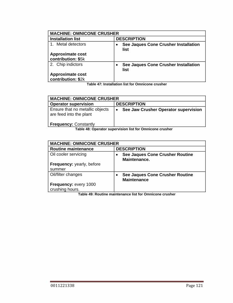
0011221338 Page 121
MACHINE: OMNICONE CRUSHER Installation list DESCRIPTION 1. Metal detectors Approximate cost contribution: $5k
• See Jaques Cone Crusher Installation list
2. Chip indictors
Approximate cost contribution: $2k
• See Jaques Cone Crusher Installation list
Table 47: Installation list for Omnicone crusher
MACHINE: OMNICONE CRUSHER Operator supervision DESCRIPTION Ensure that no metallic objects are feed into the plant Frequency: Constantly
• See Jaw Crusher Operator supervision
Table 48: Operator supervision list for Omnicone crusher
MACHINE: OMNICONE CRUSHER Routine maintenance DESCRIPTION Oil cooler servicing Frequency: yearly, before summer
• See Jaques Cone Crusher Routine Maintenance.
Oil/filter changes Frequency: every 1000 crushing hours.
• See Jaques Cone Crusher Routine Maintenance
Table 49: Routine maintenance list for Omnicone crusher
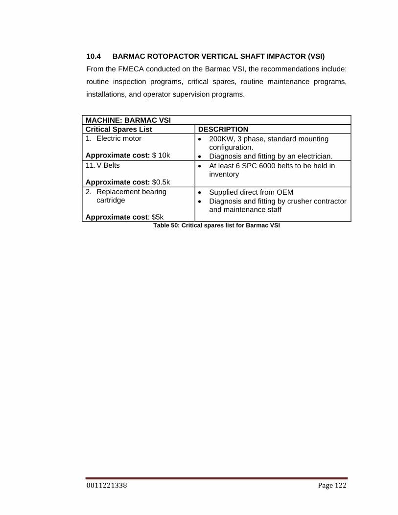
0011221338 Page 122
10.4 BARMAC ROTOPACTOR VERTICAL SHAFT IMPACTOR (VSI) From the FMECA conducted on the Barmac VSI, the recommendations include:
routine inspection programs, critical spares, routine maintenance programs,
installations, and operator supervision programs.
MACHINE: BARMAC VSI Critical Spares List DESCRIPTION 1. Electric motor Approximate cost: $ 10k
• 200KW, 3 phase, standard mounting configuration.
• Diagnosis and fitting by an electrician. 11. V Belts Approximate cost: $0.5k
• At least 6 SPC 6000 belts to be held in inventory
2. Replacement bearing
cartridge
Approximate cost: $5k
• Supplied direct from OEM • Diagnosis and fitting by crusher contractor
and maintenance staff
Table 50: Critical spares list for Barmac VSI
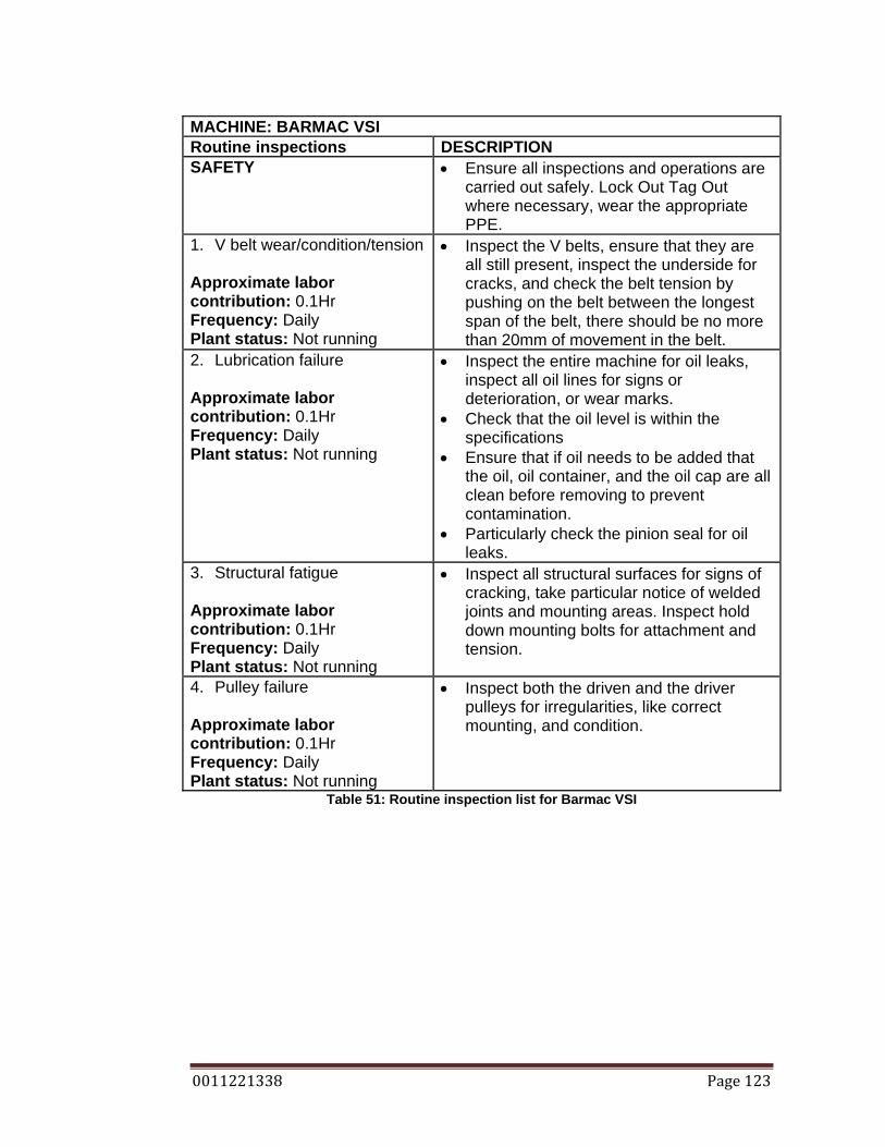
0011221338 Page 123
MACHINE: BARMAC VSI Routine inspections DESCRIPTION SAFETY • Ensure all inspections and operations are
carried out safely. Lock Out Tag Out where necessary, wear the appropriate PPE.
1. V belt wear/condition/tension Approximate labor contribution: 0.1Hr Frequency: Daily Plant status: Not running
• Inspect the V belts, ensure that they are all still present, inspect the underside for cracks, and check the belt tension by pushing on the belt between the longest span of the belt, there should be no more than 20mm of movement in the belt.
2. Lubrication failure Approximate labor contribution: 0.1Hr Frequency: Daily Plant status: Not running
• Inspect the entire machine for oil leaks, inspect all oil lines for signs or deterioration, or wear marks.
• Check that the oil level is within the specifications
• Ensure that if oil needs to be added that the oil, oil container, and the oil cap are all clean before removing to prevent contamination.
• Particularly check the pinion seal for oil leaks.
3. Structural fatigue Approximate labor contribution: 0.1Hr Frequency: Daily Plant status: Not running
• Inspect all structural surfaces for signs of cracking, take particular notice of welded joints and mounting areas. Inspect hold down mounting bolts for attachment and tension.
4. Pulley failure Approximate labor contribution: 0.1Hr Frequency: Daily Plant status: Not running
• Inspect both the driven and the driver pulleys for irregularities, like correct mounting, and condition.
Table 51: Routine inspection list for Barmac VSI
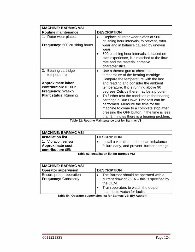
0011221338 Page 124
MACHINE: BARMAC VSI Routine maintenance DESCRIPTION 1. Rotor wear plates Frequency: 500 crushing hours
• Replace all rotor wear plates at 500 crushing hour intervals, to prevent, rotor wear and in balance caused by uneven wear.
• 500 crushing hour intervals, is based on staff experience, it is matched to the flow rate and the material abrasive characteristics.
3. Bearing cartridge temperature
Approximate labor contribution: 0.10Hr Frequency: Weekly Plant status: Running
• Use a thermo gun to check the temperature of the bearing cartridge. Compare the temperature with the last and reading and consider the ambient temperature. If it is running above 90 degrees Celsius there may be a problem.
• To further test the condition of the bearing cartridge a Run Down Time test can be performed. Measure the time for the machine to come to a complete stop after pressing the OFF button. If the time is less than 2 minutes there is a bearing problem.
Table 52: Routine Maintenance List for Barmac VSI
MACHINE: BARMAC VSI Installation list DESCRIPTION 1. Vibration sensor Approximate cost contribution: $5k
• Install a vibration to detect an imbalance failure early, and prevent further damage
Table 53: Installation list for Barmac VSI
MACHINE: BARMAC VSI Operator supervision DESCRIPTION Ensure proper operation Frequency: Constantly
• The Barmac should be operated with a current draw of 250A – this is specified by the OEM.
• Train operators to watch the output material to watch for faults.
Table 54: Operator supervision list for Barmac VSI (By Author)

0011221338 Page 125
10.5 MALCO VIBRATING SCREENS From the FMECA conducted on the Malco screens, the recommendations
include: routine inspection programs, critical spares, installations, maintenance
supervision, and operator supervision programs.
MACHINE: VIBRATING SCREENS Critical Spares List DESCRIPTION 1. Electric motor Approximate cost: $ 2k
• 7.5KW, 3 phase, standard mounting configuration.
• Diagnosis and fitting by an electrician. 2. Bearings Approximate cost: $5k
• Supplied direct from OEM • Diagnosis and fitting by crusher contractor
and maintenance staff 3. Shaft Approximate cost: $5k
• Supplied direct from OEM • Diagnosis and fitting by crusher contractor
and maintenance staff 4. V belts Approximate cost: $0.5k
• At least 6 SPC3000 belts to be held in inventory.
5. Screen mats, side rails and side rail bolts
Approximate cost: $3k
• All sized used throughout the plant to be held in inventory
Table 55: Critical spares list for Malco vibrating screen
MACHINE: VIBRATING SCREENS Routine inspections DESCRIPTION SAFETY • Ensure all inspections and operations are
carried out safely. Lock Out Tag Out where necessary, wear the appropriate PPE.
1. V belt wear/condition/tension Approximate labor contribution: 0.05Hr/screen Frequency: Daily Plant status: Not running
• Inspect the V belts, ensure that they are all still present, inspect the underside for cracks, and check the belt tension by pushing on the belt between the longest span of the belt, there should be no more than 20mm of movement in the belt.
2. Screen media condition Approximate labor contribution: 0.005Hr/screen Frequency: Daily
• Inspect the screen mats for each deck, check for hole, blockages, and screen wear. Inspect the side rails for wear. Check that the heads of the side rail bolts are not worn down to far that they may

0011221338 Page 126
Plant status: Not running pull through the side rail and allow the screen mat to become lose.
3. Structural fatigue Approximate labor contribution: 0.1Hr/screen Frequency: Daily Plant status: Not running
• Inspect all structural surfaces for signs of cracking, take particular notice of welded joints and mounting areas. Inspect hold down mounting bolts for attachment and tension.
Table 56: Routine inspection list for Malco vibrating screen
MACHINE: VIBRATING SCREENS Routine maintenance DESCRIPTION SAFETY • Ensure all inspections and operations are
carried out safely. Lock Out Tag Out where necessary, wear the appropriate PPE.
1. Bearing lubrication
Approximate labor contribution: 0.5hr for all Frequency: Bi daily Plant status: Not running
• Apply lubrication to the screen bearings. Apply 5grams of EP2 grease to each bearing
2. Bearing temperature checks Approximate labor contribution: 0.5hr for all Frequency: Weekly Plant status: Running
• Use a temperature gun to check the temperature of each bearing and record. If the bearing temperature is greater than 60 degrees Celsius, there is a problem, that requires further investigation.
• Conduct an audio inspection on each bearing. Make note of irregularities
3. Housekeeping Approximate labor contribution: 0.25hr for all Frequency: daily Plant status: Not running
• Enforce housekeeping throughout the plant area, this would include: under tail drums, walkways, structural feet, screen interference.
4. Screen media
• Collect data on the time to failure for each particular screen deck.
• Change screen decks as the information found.
• Start a screen log, which details when each screen was last changed.
Table 57: Routine maintenance list for Malco vibrating screen

0011221338 Page 127
MACHINE: VIBRATING SCREENS Operator supervision DESCRIPTION 1. Ensure proper operation Frequency: Constantly
• Train operators to watch the output material to watch for contamination of larger rocks that the screened size.
Table 58: Operator supervision list for Malco vibrating screen
MACHINE: VIBRATING SCREENS Maintenance supervision DESCRIPTION 1. Ensure proper fitting of
screen mats Frequency: Constantly
• Train workers to ensure that the side rails are correctly bottomed out in the mating shape of the screen mat, to prevent the screen from working loose.
• Ensure that the side rail bolts are tight. Table 59: Maintenance supervision list for Malco vibrating screen
MACHINE: VIBRATING SCREENS Routine testing DESCRIPTION 1. Lubrication sampling Frequency: 6 monthly
• Take a sample of the lubrication and test for metal content.
Table 60: Routine testing list for Malco vibrating screen
MACHINE: VIBRATING SCREENS Installation list DESCRIPTION 1. Peak vibration sensor Approximate cost contribution: 2K
• A screen has a high vibration under normal conditions, but if a peak vibration sensor is fitted it may detect if a fault has occurred.
Table 61: Installation list for Malco vibrating screen

0011221338 Page 128
10.6 MATERIAL HANDLING CONVEYORS From the FMECA conducted on material handling conveyors, the
recommendations include: routine inspection programs, routine maintenance
program, critical spares, installations, housekeeping, maintenance supervision,
and operator supervision programs.
MACHINE: MATERIAL HANDLING CONVEYORS Critical Spares List DESCRIPTION 1. Electric motor Approximate cost: $ 2k
• 30KW, 15KW X 2, 11.5KW X 3, 7.5KW X 2, 5KW, 3 phase, standard mounting configuration.
• Diagnosis and fitting by an electrician. 2. Head and tail drum bearings Approximate cost: $5k
• Supplied direct from SKF • Diagnosis and fitting by maintenance staff
3. Speed reducing gearboxes Approximate cost: $5k
• Supplied direct from preferred supplier • Diagnosis and fitting by maintenance staff
4. V belts Approximate cost: $2k
• A selection of the required belts are necessary
5. Head and tail drums Approximate cost: $3k
• All sizes used throughout the plant to be held in inventory
Table 62: Critical spares list for Material handling conveyors
MACHINE: MATERIAL HANDLING CONVEYORS Routine inspections DESCRIPTION SAFETY • Ensure all inspections and operations are
carried out safely. Lock Out Tag Out where necessary, wear the appropriate PPE.
1. V belt wear/condition/tension Approximate labor contribution: 0.05Hr/conveyor Frequency: Daily Plant status: Not running
• Inspect the V belts, ensure that they are all still present, inspect the underside for cracks, and check the belt tension by pushing on the belt between the longest span of the belt, there should be no more than 20mm of movement in the belt.
• Also inspect the V belt alignment. Check that the belt is running straight and there does seem to be a fault with the taper lock, which holds the pulley to the shaft.
2. Screen media condition • Inspect the screen mats for each deck,
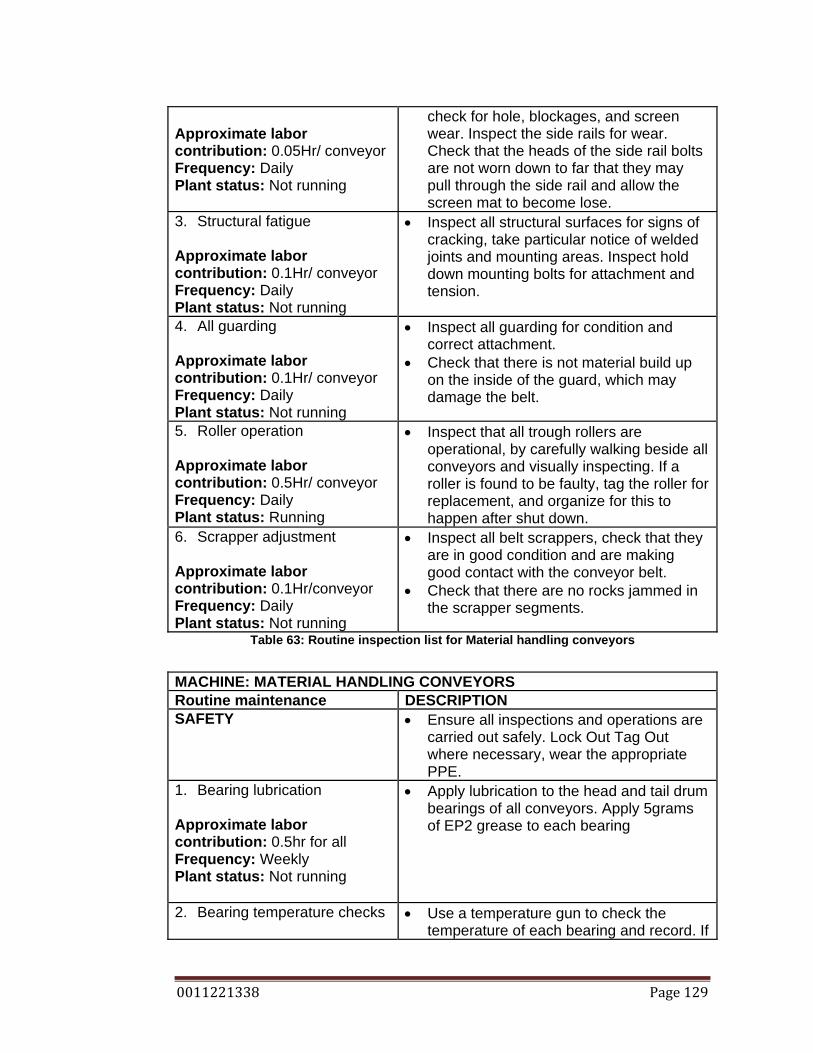
0011221338 Page 129
Approximate labor contribution: 0.05Hr/ conveyor Frequency: Daily Plant status: Not running
check for hole, blockages, and screen wear. Inspect the side rails for wear. Check that the heads of the side rail bolts are not worn down to far that they may pull through the side rail and allow the screen mat to become lose.
3. Structural fatigue Approximate labor contribution: 0.1Hr/ conveyor Frequency: Daily Plant status: Not running
• Inspect all structural surfaces for signs of cracking, take particular notice of welded joints and mounting areas. Inspect hold down mounting bolts for attachment and tension.
4. All guarding Approximate labor contribution: 0.1Hr/ conveyor Frequency: Daily Plant status: Not running
• Inspect all guarding for condition and correct attachment.
• Check that there is not material build up on the inside of the guard, which may damage the belt.
5. Roller operation Approximate labor contribution: 0.5Hr/ conveyor Frequency: Daily Plant status: Running
• Inspect that all trough rollers are operational, by carefully walking beside all conveyors and visually inspecting. If a roller is found to be faulty, tag the roller for replacement, and organize for this to happen after shut down.
6. Scrapper adjustment Approximate labor contribution: 0.1Hr/conveyor Frequency: Daily Plant status: Not running
• Inspect all belt scrappers, check that they are in good condition and are making good contact with the conveyor belt.
• Check that there are no rocks jammed in the scrapper segments.
Table 63: Routine inspection list for Material handling conveyors
MACHINE: MATERIAL HANDLING CONVEYORS Routine maintenance DESCRIPTION SAFETY • Ensure all inspections and operations are
carried out safely. Lock Out Tag Out where necessary, wear the appropriate PPE.
1. Bearing lubrication
Approximate labor contribution: 0.5hr for all Frequency: Weekly Plant status: Not running
• Apply lubrication to the head and tail drum bearings of all conveyors. Apply 5grams of EP2 grease to each bearing
2. Bearing temperature checks
• Use a temperature gun to check the temperature of each bearing and record. If
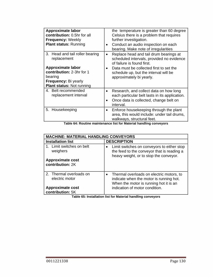
0011221338 Page 130
Approximate labor contribution: 0.5hr for all Frequency: Weekly Plant status: Running
the temperature is greater than 60 degree Celsius there is a problem that requires further investigation.
• Conduct an audio inspection on each bearing. Make note of irregularities
3. Head and tail roller bearing replacement
Approximate labor contribution: 2-3hr for 1 bearing Frequency: Bi yearly Plant status: Not running
• Replace head and tail drum bearings at scheduled intervals, provided no evidence of failure is found first.
• Data must be collected first to set the schedule up, but the interval will be approximately bi yearly.
4. Belt recommended replacement interval
• Research, and collect data on how long each particular belt lasts in its application.
• Once data is collected, change belt on interval.
5. Housekeeping • Enforce housekeeping through the plant area, this would include: under tail drums, walkways, structural feet.
Table 64: Routine maintenance list for Material handling conveyors
MACHINE: MATERIAL HANDLING CONVEYORS Installation list DESCRIPTION 1. Limit switches on belt
weighers
Approximate cost contribution: 2K
• Limit switches on conveyors to either stop the feed to the conveyor that is reading a heavy weight, or to stop the conveyor.
2. Thermal overloads on electric motor
Approximate cost contribution: 5K
• Thermal overloads on electric motors, to indicate when the motor is running hot. When the motor is running hot it is an indication of motor condition.
Table 65: Installation list for Material handling conveyors

0011221338 Page 131
10.7 MATERIAL HANDLING TRANSFER POINTS
From the FMECA conducted on material handling transfer points, the
recommendations include: routine inspection programs, routine maintenance
program, maintenance supervision, and installations/engineering judgment.
MACHINE: MATERIAL HANDLING TRANSFER POINTS Installation list DESCRIPTION 1. Side skirt rubber Approximate cost contribution: 0.5K
• A role of side skirt rubber needs to be held in inventory at all times.
Table 66: Critical spares list for Material handling transfer points
MACHINE: MATERIAL HANDLING TRANSFER POINTS Routine inspection DESCRIPTION SAFETY • Ensure all inspections and operations are
carried out safely. Lock Out Tag Out where necessary, wear the appropriate PPE.
• Works carried out by maintenance staff 1. Side skirts Approximate labor contribution: 0.15 Hr/trans p. Frequency: Daily Plant status: Not running
• Inspect all side skirts, for condition and belt contact. If the side skirt is not contacting the belt, adjust it, by releasing the side clamps, pushing the rubber down and tightening the side clamps again. If the side skirt is in bad condition, replace it; using the same sequence as when adjusting the side skirt
• Works carried out by maintenance staff 2. Wear liners Approximate labour contribution: 0.15 Hr/trans p. Frequency: Weekly Plant status: Not running
• Inspect the transfer point wear liners. Check that they are attached correctly and are not excessively worn. Excessive wear will be evident when the wear plate has thin sections in it.
• Collect data on wear liner replacement intervals, and create a log to predetermine the wear.
• Works carried out by maintenance staff 3. Blockages • Inspect all transfer points for material build
up which may lead to a blockage during the day. If so remove with appropriate tooling.
• Works carried out by maintenance staff Table 67: Routine inspection list for Material handling transfer points

0011221338 Page 132
MACHINE: MATERIAL HANDLING TRANSFER POINTS Maintenance supervision DESCRIPTION 1. Side skirts Approximate labor contribution: 0.15 Hr/trans p. Frequency: Daily Plant status: Not running
• It may the case that side skirts need to be adjusted at least once a week. So for this reason, workers may get complacent, so ensure that all side clamp bolts are correctly tensioned, and that side skirts are fitted properly
Table 68: Maintenance supervision list for Material handling transfer points
MACHINE: MATERIAL HANDLING TRANSFER POINTS Routine maintenance DESCRIPTION 1. Wear plate replacement Approximate labor contribution: 3Hr/plate Frequency: Scheduled Plant status: Not running
• See Routine Inspections Material Handling Transfer Points
Table 69: Routine maintenance list for Material handling transfer points
MACHINE: MATERIAL HANDLING TRANSFER POINTS Installation list DESCRIPTION 1. Limit switches in prone
blockage areas
Approximate cost contribution: 2K
• Limit switches inside the transfer points, that constantly block, strategically placed to indicate if a blockage is about to occur, so that the plant can be stopped and the material removed without causing damage to the belt.
2. Structural enhancements Approximate cost contribution:
• Conduct an audit on the structural members of the transfer points, to identify unsound components.
3. Redesign problem transfer points
• Redesign transfer points that may be causing blockages.
Table 70: Installation list for Material handling transfer points
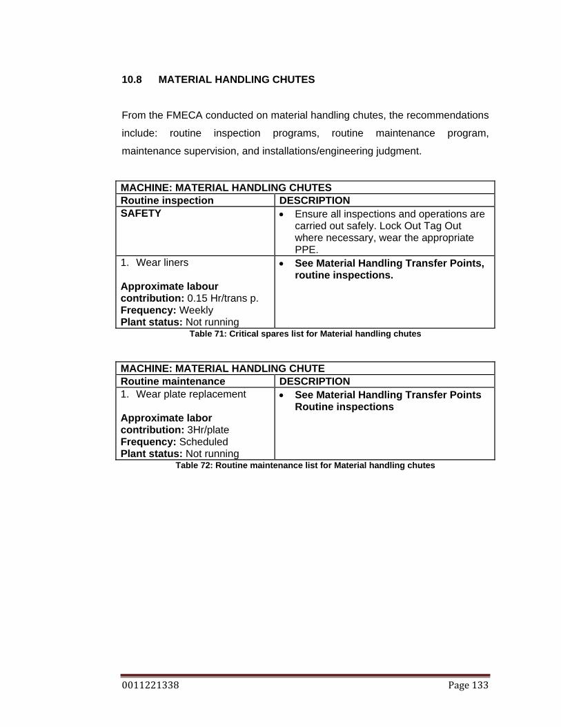
0011221338 Page 133
10.8 MATERIAL HANDLING CHUTES
From the FMECA conducted on material handling chutes, the recommendations
include: routine inspection programs, routine maintenance program,
maintenance supervision, and installations/engineering judgment.
MACHINE: MATERIAL HANDLING CHUTES Routine inspection DESCRIPTION SAFETY • Ensure all inspections and operations are
carried out safely. Lock Out Tag Out where necessary, wear the appropriate PPE.
1. Wear liners Approximate labour contribution: 0.15 Hr/trans p. Frequency: Weekly Plant status: Not running
• See Material Handling Transfer Points, routine inspections.
Table 71: Critical spares list for Material handling chutes
MACHINE: MATERIAL HANDLING CHUTE Routine maintenance DESCRIPTION 1. Wear plate replacement Approximate labor contribution: 3Hr/plate Frequency: Scheduled Plant status: Not running
• See Material Handling Transfer Points Routine inspections
Table 72: Routine maintenance list for Material handling chutes
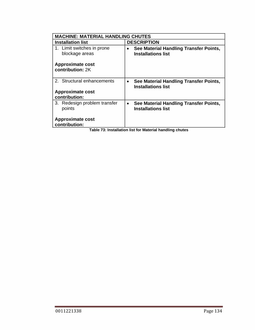
0011221338 Page 134
MACHINE: MATERIAL HANDLING CHUTES Installation list DESCRIPTION 1. Limit switches in prone
blockage areas
Approximate cost contribution: 2K
• See Material Handling Transfer Points, Installations list
2. Structural enhancements Approximate cost contribution:
• See Material Handling Transfer Points, Installations list
3. Redesign problem transfer points
Approximate cost contribution:
• See Material Handling Transfer Points, Installations list
Table 73: Installation list for Material handling chutes

0011221338 Page 135
10.9 16 AGGREGATE STORAGE BINS AND THE SURGE BIN From the FMECA conducted on the aggregate storage bins and the surge bin,
the recommendations include: maintenance supervision programs, routine
inspection programs, routine maintenance programs and
installations/engineering judgment.
MACHINE: AGGREGATE STORAGE BINS AND SURGE BIN Maintenance supervision DESCRIPTION 1. Fitting Approximate labor contribution: Frequency: Daily Plant status: Not running
• Ensure that all fitting works are carried out correctly: all fasteners are in place and are all secure.
Table 74: Maintenance supervision list for aggregate storage bins and surge bin
MACHINE: AGGREGATE STORAGE BINS AND SURGE BIN Routine inspection DESCRIPTION SAFETY • Ensure all inspections and operations are
carried out safely. Lock Out Tag Out where necessary, wear the appropriate PPE.
1. Wear liners Approximate labor contribution: 0.15 Hr/trans p. Frequency: Weekly Plant status: Not running
• See Material Handling Transfer Points, routine inspections.
Table 75: Routine inspection list for aggregate storage bins and surge bin
MACHINE: AGGREGATE STORAGE BINS AND SURGE BIN Routine maintenance DESCRIPTION 1. Wear plate replacement Approximate labor contribution: 3Hr/plate Frequency: Scheduled Plant status: Not running
• See Routine Inspections Material Handling Transfer Points
Table 76: Routine maintenance list for aggregate storage bins and surge bin
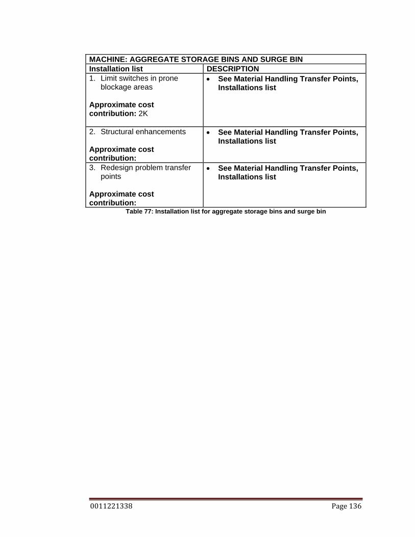
0011221338 Page 136
MACHINE: AGGREGATE STORAGE BINS AND SURGE BIN Installation list DESCRIPTION 1. Limit switches in prone
blockage areas
Approximate cost contribution: 2K
• See Material Handling Transfer Points, Installations list
2. Structural enhancements Approximate cost contribution:
• See Material Handling Transfer Points, Installations list
3. Redesign problem transfer points
Approximate cost contribution:
• See Material Handling Transfer Points, Installations list
Table 77: Installation list for aggregate storage bins and surge bin

0011221338 Page 137
10.10 AGGREGATE BIN LEVEL SENSORS From the FMECA conducted on the aggregate bin level sensors, the
recommendations include: critical spares. Since the system is electrical the
serviceability is reduced. The wirering has been designed so that if a tilt level
sensor fails, a new one can be fitted by plugging a new sensor into an ordinary
power socket
MACHINE: AGGREGATE BIN LEVEL SENSORS Critical Spares List DESCRIPTION 1. Tilt level sensors Approximate cost: $ 0.5k each
• Supplied by electrician. • Diagnosis and fitting by an electrician.
Table 78: Critical spares list for aggregate bin level sensors
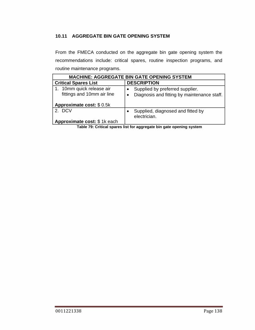
0011221338 Page 138
10.11 AGGREGATE BIN GATE OPENING SYSTEM From the FMECA conducted on the aggregate bin gate opening system the
recommendations include: critical spares, routine inspection programs, and
routine maintenance programs.
MACHINE: AGGREGATE BIN GATE OPENING SYSTEM Critical Spares List DESCRIPTION 1. 10mm quick release air
fittings and 10mm air line Approximate cost: $ 0.5k
• Supplied by preferred supplier. • Diagnosis and fitting by maintenance staff.
2. DCV Approximate cost: $ 1k each
• Supplied, diagnosed and fitted by electrician.
Table 79: Critical spares list for aggregate bin gate opening system
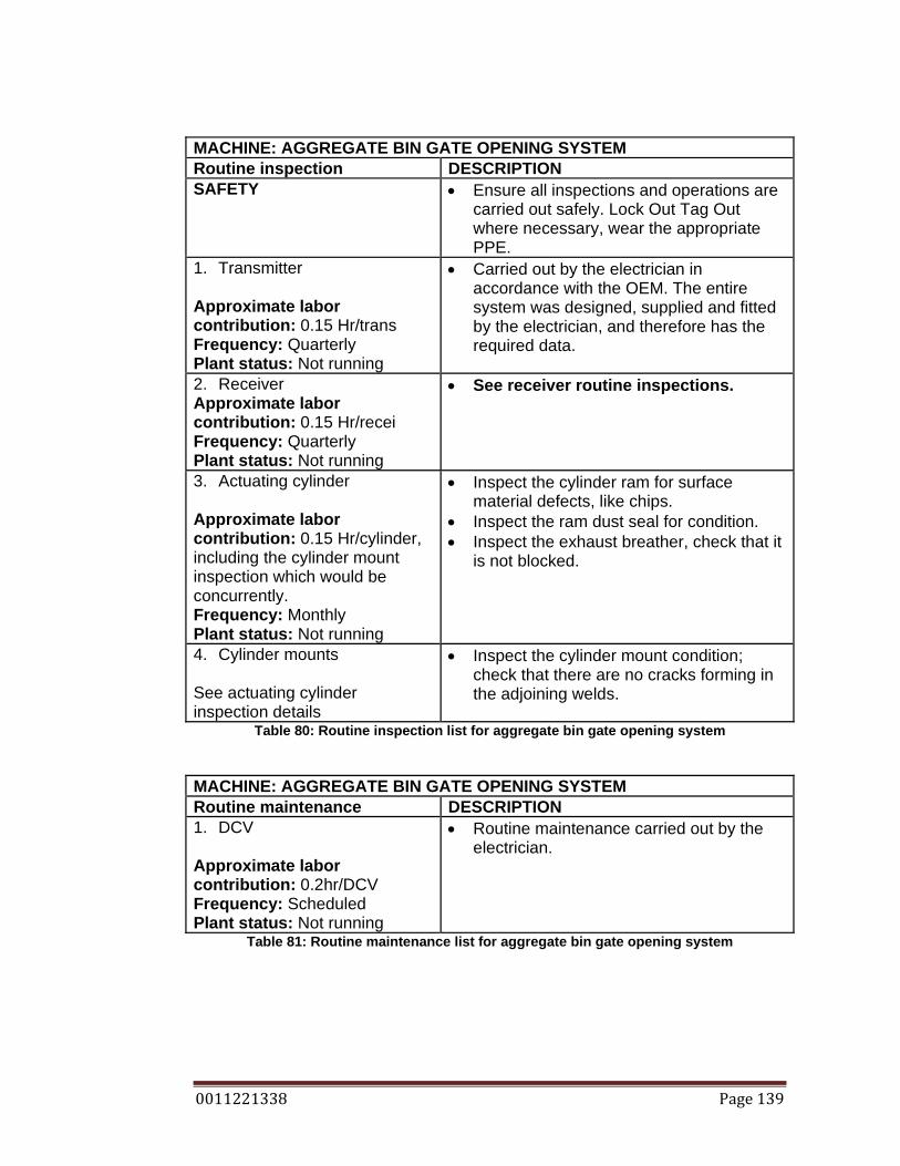
0011221338 Page 139
MACHINE: AGGREGATE BIN GATE OPENING SYSTEM Routine inspection DESCRIPTION SAFETY • Ensure all inspections and operations are
carried out safely. Lock Out Tag Out where necessary, wear the appropriate PPE.
1. Transmitter Approximate labor contribution: 0.15 Hr/trans Frequency: Quarterly Plant status: Not running
• Carried out by the electrician in accordance with the OEM. The entire system was designed, supplied and fitted by the electrician, and therefore has the required data.
2. Receiver Approximate labor contribution: 0.15 Hr/recei Frequency: Quarterly Plant status: Not running
• See receiver routine inspections.
3. Actuating cylinder Approximate labor contribution: 0.15 Hr/cylinder, including the cylinder mount inspection which would be concurrently. Frequency: Monthly Plant status: Not running
• Inspect the cylinder ram for surface material defects, like chips.
• Inspect the ram dust seal for condition. • Inspect the exhaust breather, check that it
is not blocked.
4. Cylinder mounts See actuating cylinder inspection details
• Inspect the cylinder mount condition; check that there are no cracks forming in the adjoining welds.
Table 80: Routine inspection list for aggregate bin gate opening system
MACHINE: AGGREGATE BIN GATE OPENING SYSTEM Routine maintenance DESCRIPTION 1. DCV Approximate labor contribution: 0.2hr/DCV Frequency: Scheduled Plant status: Not running
• Routine maintenance carried out by the electrician.
Table 81: Routine maintenance list for aggregate bin gate opening system
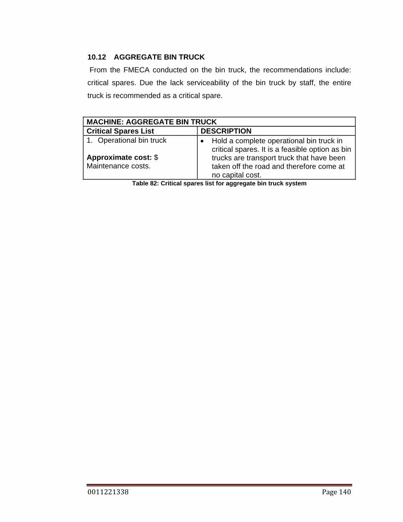
0011221338 Page 140
10.12 AGGREGATE BIN TRUCK From the FMECA conducted on the bin truck, the recommendations include:
critical spares. Due the lack serviceability of the bin truck by staff, the entire
truck is recommended as a critical spare.
MACHINE: AGGREGATE BIN TRUCK Critical Spares List DESCRIPTION 1. Operational bin truck Approximate cost: $ Maintenance costs.
• Hold a complete operational bin truck in critical spares. It is a feasible option as bin trucks are transport truck that have been taken off the road and therefore come at no capital cost.
Table 82: Critical spares list for aggregate bin truck system
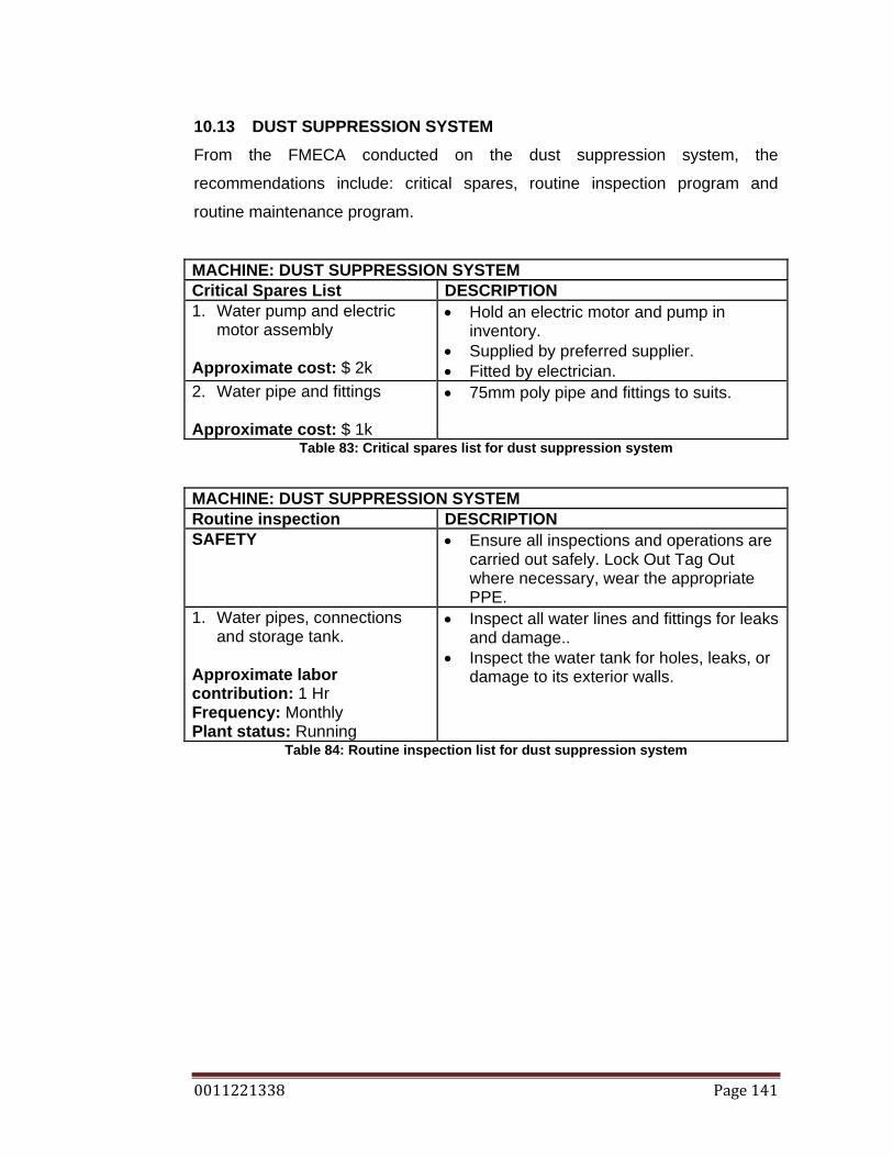
0011221338 Page 141
10.13 DUST SUPPRESSION SYSTEM From the FMECA conducted on the dust suppression system, the
recommendations include: critical spares, routine inspection program and
routine maintenance program.
MACHINE: DUST SUPPRESSION SYSTEM Critical Spares List DESCRIPTION 1. Water pump and electric
motor assembly Approximate cost: $ 2k
• Hold an electric motor and pump in inventory.
• Supplied by preferred supplier. • Fitted by electrician.
2. Water pipe and fittings Approximate cost: $ 1k
• 75mm poly pipe and fittings to suits.
Table 83: Critical spares list for dust suppression system
MACHINE: DUST SUPPRESSION SYSTEM Routine inspection DESCRIPTION SAFETY • Ensure all inspections and operations are
carried out safely. Lock Out Tag Out where necessary, wear the appropriate PPE.
1. Water pipes, connections and storage tank.
Approximate labor contribution: 1 Hr Frequency: Monthly Plant status: Running
• Inspect all water lines and fittings for leaks and damage..
• Inspect the water tank for holes, leaks, or damage to its exterior walls.
Table 84: Routine inspection list for dust suppression system

0011221338 Page 142
MACHINE: DUST SUPPRESSION SYSTEM Routine maintenance DESCRIPTION 1. Water pump and water filter Approximate labor contribution: 0.25hr Frequency: Scheduled Plant status: Not running
• Clean the water filter at regular intervals, and replace the water filter at regular intervals. Clean: Weekly, Replace: Monthly.
2. Water pump Approximate labor contribution: 2hr Frequency: Scheduled Plant status: Not running
• Dismantle the water pump, clean the impeller, and possibly replace the shaft bearings at regular intervals.
• Replace water pump at regular intervals.
Table 85: Routine maintenance list for dust suppression system

0011221338 Page 143
10.14 COMP AIR HYDRAULIC ROCK BREAKER. From the FMECA conducted on the rock breaker, the recommendations
include: critical spares, routine inspection program routine maintenance
program, and installations.
MACHINE: COMP AIR ROCK BREAKER Critical Spares List DESCRIPTION 1. Electric motor Approximate cost: $ 3k
• Hold an electric motor in inventory. • Diagnosed, supplied and fitted by
electrician. 2. Rock breaker attachment Approximate cost: $ 7k
• Hold a complete rock breaker attachment in inventory or a spares kit.
3. Prone Hydraulic lines Approximate cost: $ 0.5k
• Hold in inventory spare hydraulic lines, that are prone to defects by operation.
4. Hydraulic pump Approximate cost: $ 1k
• Hold in inventory a hydraulic pump, or spares kit
Table 86: Critical spares list for Comp Air rock breaker
MACHINE: COMP AIR ROCK BREAKER Routine inspection DESCRIPTION SAFETY • Ensure all inspections and operations are
carried out safely. Lock Out Tag Out where necessary, wear the appropriate PPE.
1. Hydraulic system Approximate labor contribution: 0.1Hr Frequency: Daily Plant status: Not running
• Inspect the oil level, using the sight glass, ensure that the oil level is within the marked specifications.
• Inspect all oil lines for leaks and damage. • Inspect the hammer for oil leaks
Table 87: Routine inspection list for Comp Air rock breaker

0011221338 Page 144
MACHINE: COMP AIR ROCK BREAKER Routine maintenance DESCRIPTION 1. Oil and oil filter changes Approximate labor contribution: 1hr Frequency: Scheduled Plant status: Not running
• Change the hydraulic oil filter at scheduled intervals.
2. Oil cooler Approximate labor contribution: 2hr Frequency: Scheduled Plant status: Not running
• Remove and clean the oil cooler at scheduled intervals.
Table 88: Routine maintenance list for Comp Air rock breaker
MACHINE: COMP AIR ROCK BREAKER Installation list DESCRIPTION 1. Chip indicators Approximate cost contribution: $1K
• Install chip indicators into the hydraulic system, to indicator an internal failure in the hydraulic system.
2. Flow switch Approximate cost contribution: $1k
• Install a flow switch in the hydraulic system to indicate when there is low oil flow.
Table 89: Installation list for Comp Air rock breaker

0011221338 Page 145
10.15 ATLAS COPCO AIR COMPRESSOR. From the FMECA conducted on the air compressor, the recommendations
include: routine inspection program routine maintenance program. The air
compressor is unserviceable by staff, and is maintained using scheduled
maintenance set by the Original Equipment Manufacturer (OEM), with the works
carried by the OEM.
MACHINE: ATLAS COPCO AIR COMPRESSOR Routine inspection DESCRIPTION SAFETY • Ensure all inspections and operations are
carried out safely. Lock Out Tag Out where necessary, wear the appropriate PPE.
1. General system Approximate labor contribution: 0.1Hr Frequency: Daily Plant status: Not running
• Walk around the air compressor and inspect the machine. Look for any irregularities like: oil leaks, water leaks, air leaks, loose bolts, guards in place etc.
2. Air lines Approximate labor contribution: 0.1Hr Frequency: Daily Plant status: Running
• Inspect all air lines for leaks and damaged piping.
Table 90: Routine inspection list for Atlas Copco air compressor

0011221338 Page 146
10.16 STRUCTURAL FRAMING From the FMECA conducted on the structural framing, the recommendations
include routine inspection program, and routine housekeeping.
MACHINE: STRUCTURAL FRAMING Routine inspection DESCRIPTION SAFETY • Ensure all inspections and operations are
carried out safely. Lock Out Tag Out where necessary, wear the appropriate PPE.
1. Structural joints Approximate labor contribution: 1Hr Frequency: Monthly Plant status: Not running
• Inspect all structural joints. Ensure that there are no signs of corrosion, cracks, and that all mounting bolts are secure.
2. Excessive vibration Approximate labor contribution: 1Hr Frequency: Monthly Plant status: Running
• Inspect the plant for excessive vibrations by walking all components while the plant is running.
3. Firefighting equipment in place.
Approximate labor contribution: 1Hr Frequency: Monthly Plant status: Running
• Conduct an audit to ensure that all fire extinguishers are in place.
Table 91: Routine inspection list for structural framing

0011221338 Page 147
MACHINE: STRUCTURAL FRAMING Routine house keeping DESCRIPTION 1. Remove material spillage
from walkways Approximate labor contribution: 1Hr Frequency: Daily Plant status: Running
• Remove all material spillage from walkways to prevent trip hazards.
2. Remove material from structural frame hold down plates.
Approximate labor contribution: 1Hr Frequency: Daily Plant status: Running
• Remove all material build up from the structural frame hold down plates to prevent accelerated corrosion.
Table 92: Routine inspection list for structural framing

0011221338 Page 148
10.17 ELECTRICS
From the FMECA conducted on the plant electrics, the recommendations
include routine inspection program, and critical spares. Electricians will be
consulted for critical spares
MACHINE: ELECTRIC SYSTEM Critical Spares List DESCRIPTION 1. Switches, fuses, and starters Approximate cost: $ 2k
• Liaise with the electrician to hold in the suppliers inventory, critical spares of the required sizes.
Table 93: Critical spares list for electrics
MACHINE: ELECTRIC SYSTEM Routine maintenance DESCRIPTION 1. Electrical system Approximate labor contribution: On going. Frequency: Scheduled Plant status: Not running
• Liaise with the electrician to develop a suitable maintenance program from the electrical system
Table 94: Routine maintenance list for electrics

0011221338 Page 149
11. CONCLUSIONS
An aim was developed to reduce the unscheduled downtime of the crushing
and screening plant at the BORAL Quarry site at Ormeau. Unscheduled
downtime being undesirable due to the lost of profits accumulated while the
plant is down, and the prospect of running out of material during a major
construction job that BORAL is suppling. To try to reduce the unscheduled
downtime figure it was decided to undertake an FMECA process on the entire
plant. The FMECA, or Failure Mode, Effect and Criticality Analysis, is a simple
systematic procedure to preventing failures, predicting failures, identifying
problems, helping to plan maintenance, and helping to develop measures to
quickly repair failures by having the required parts, and staff knowledge to be
able to do some of the repairs.
The first step in the FMECA process was to review the current plant downtime
data, it revealed some problem machines, which were identified by large
downtime contributions of the downtime graphs. This helped in evaluating the
‘Frequency of Failure’ in the FMECA. The next step was to define the entire
plant requirements, which included, the regulations that it must operate within,
the expected system performances, and what constitutes a failure for this plant.
It was decided that a 25% loss in production constitutes a failure. The next step
in the FMECA process was to study and define the plant. This identified that all
machines were on the critical production path and that no machine could fail
and still allow the plant to produce. This piece of information is proportional to
the ‘severity’ rating used in the FMECA. Any complete system failing will result
in the plants full loss of production and therefore has a high severity. The next
step was to understand the operation of each machine. This entailed a detail
study into every component of the plant process. This understanding of the
machines used allowed the next step, which was to develop functional
diagrams. The functional diagrams showed if there were any dependencies with
in a machine. What could fail and still allow the machine to run and further the
plant process. There were not a lot of component that could fail and still allow
the plant to function, all components were identified and stated in chapter 6.

0011221338 Page 150
This information was useful to determine what could possibly fail, and the
severity of a failure.
It was decided that the items of evaluation for each failure would include:
frequency of occurrence, severity, detection, and an RPN. It was necessary to
develop ground rules for the FMECA, to obtain consistency across the report.
The evaluation process relied on engineering judgment, experience, downtime
data, critical path analysis, dependency analysis, and knowledge of the plant.
After the RPN was calculated, recommendations were made to combat that
particular failure. Some recommendations include: routine inspection programs,
routine maintenance programs, maintenance supervision programs, operator
supervision programs, critical spares, installations, and many more.
The recommendations were expanded to give particular details. The
recommendations could be implemented by staff to improve plant maintenance.
An estimate as to how long an action may take and the frequency works.
The FMECA process was conducted on the crushing and screening plant at
Ormeau. Recommendations were made and implementation instruction were
given. Therefore a process has been undertaken and applied to a real situation.

0011221338 Page 151
12. LIST OF REFERENCES
ADC Jaw Crusher Information 2009, Aggregate Design Corporation , Colorado, viewed 25 July, 2009, <http://www.aggdesigns.com/Jaw-Crusher-info.htm>
Allis Tidco International 1988 Operators manual and parts list 9600 rotopactor vertical
shaft impact crusher, Allis Tidco International, Matamata Banerji, R & Chakraborty, D 2009, ‘Lifecycle FMECA’, AMMJ: Asset management &
maintenance journal, vol. 22, no. 2 pp. 32-34. Bennett, S, Norman, I 2006 Heavy duty truck systems 4th Edition, Thomson Delmar
Learning, New York Camilleri, D 2002, ‘Rethinking engineering: risk and reliability analysis’, Structural
Engineer, vol. 80, no. 8 pp 13-14 Cooke, JR 2001, Architects, Engineers & the Law, The Federation Press, Sydney.
Cox, R 2008, ‘Reliability and Failure Analysis of Cone Crushers in BORAL Aggregate
Production’, BE dissertation, Queensland University of Technology.
ENG4111/4112 Research Project: Project Reference Book 2009, University of Southern Queensland, Toowoomba.
Hoffman, J 2008 ‘Supplier Specification – Asphalt – SS002 Boral Quarry’ Document
supplied as Boral Quality Assurance Procedure, Gold Coast, 2008. Holley, H (2009) letter to Gold Coast City Council, 25th June. Institute of Quarrying Australia 2009, Electrical awareness for quarry managers and
supervisors, Institute of Quarrying Australia, Sydney.
International Electrotechnical Commission Standard 1985, Analysis techniques for system reliability – Procedure for failure mode and effects analysis (FMEA), International Electrotechnical Commission Standard, Geneva.
Jacques Bros. Ltd 1957, Instruction manual for traylor type gyratory crushers, Jacques
Bros. Ltd Melbourne Lark, RJ & Flaig, KD 2005, ‘The use of reliability analysis to aid bridge management’,
The Structural Engineer, vol. 83, no. 5 pp. 27-31. Malco Industries Ltd 1986, Model CASM vibrating screen instruction manual, Malco
Industries Ltd, Croydon Park
Nordberg 1987, Omnicone crusher instruction manual, Nordberg Brisbane
Quarry reporting system (QRS) database, Boral Construction Materials QLD, monthly updating.

0011221338 Page 152
Rigby, M 2001, Boral Quarries, Integrated environmental management system, Mark Rigby and Associates, Brisbane
Sandvik, S 2007, Sandvick CS440:01 operator’s manual, Sandvick SRP AB Swinderman R, Goldbeck, L & Marti A 2002, Foundations 3, The practical resource for
total dust & material control, Martin Engineering Illinois
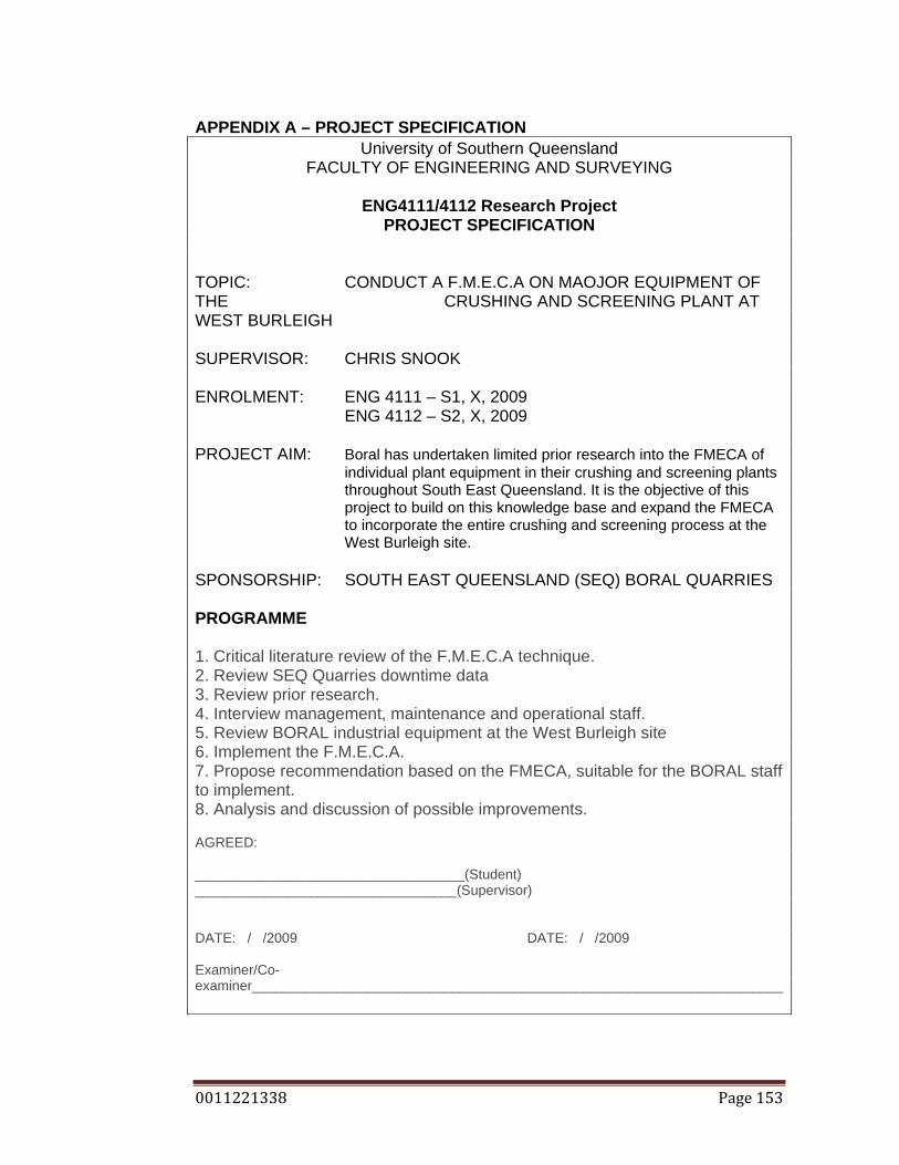
0011221338 Page 153
APPENDIX A – PROJECT SPECIFICATION University of Southern Queensland
FACULTY OF ENGINEERING AND SURVEYING
ENG4111/4112 Research Project PROJECT SPECIFICATION
TOPIC: CONDUCT A F.M.E.C.A ON MAOJOR EQUIPMENT OF THE CRUSHING AND SCREENING PLANT AT WEST BURLEIGH SUPERVISOR: CHRIS SNOOK ENROLMENT: ENG 4111 – S1, X, 2009 ENG 4112 – S2, X, 2009 PROJECT AIM: Boral has undertaken limited prior research into the FMECA of
individual plant equipment in their crushing and screening plants throughout South East Queensland. It is the objective of this project to build on this knowledge base and expand the FMECA to incorporate the entire crushing and screening process at the West Burleigh site.
SPONSORSHIP: SOUTH EAST QUEENSLAND (SEQ) BORAL QUARRIES PROGRAMME 1. Critical literature review of the F.M.E.C.A technique. 2. Review SEQ Quarries downtime data 3. Review prior research. 4. Interview management, maintenance and operational staff. 5. Review BORAL industrial equipment at the West Burleigh site 6. Implement the F.M.E.C.A. 7. Propose recommendation based on the FMECA, suitable for the BORAL staff to implement. 8. Analysis and discussion of possible improvements. AGREED: ___________________________________(Student) __________________________________(Supervisor) DATE: / /2009 DATE: / /2009 Examiner/Co-examiner_____________________________________________________________________

0011221338 Page 154
APPENDIX B – PROJECT PROGRAMME

0011221338 Page 155
APPENDIX C – PROJECT RISK REGISTER

0011221338 Page 156
APPENDIX D – DAILY CRUSHING DATA SHEET