UNIVERSITY OF NAIROBImechanical.uonbi.ac.ke/sites/default/files/cae/engineering... · UNIVERSITY OF...
60
1 UNIVERSITY OF NAIROBI SCHOOL OF ENGINEERING DEPARTMENT OF MECHANICAL AND MANUFACTURING ENGINEERING FINAL YEAR PROJECT REPORT [FME 561 &562] PROJECT TITLE: DESIGN OF A SOLAR POULTRY EGG INCUBATOR PROJECT CODE: RMK 01/2012 SUPERVISOR: MR. R.M. KIVINDU COMPILED BY: KITHEKA GEORGE MBOKA F18/20355/2007 KING’OO GEORGE MAUNDU F18/1885/2007 This project report is submitted in partial fulfillment of the requirement for the award of the degree of Bachelor of Science in Mechanical Engineering.
Transcript of UNIVERSITY OF NAIROBImechanical.uonbi.ac.ke/sites/default/files/cae/engineering... · UNIVERSITY OF...

1
UNIVERSITY OF NAIROBI
SCHOOL OF ENGINEERING
DEPARTMENT OF MECHANICAL AND MANUFACTURING
ENGINEERING
FINAL YEAR PROJECT REPORT
[FME 561 &562]
PROJECT TITLE:
DESIGN OF A SOLAR POULTRY EGG INCUBATOR
PROJECT CODE: RMK 01/2012
SUPERVISOR: MR. R.M. KIVINDU
COMPILED BY:
KITHEKA GEORGE MBOKA F18/20355/2007
KING’OO GEORGE MAUNDU F18/1885/2007
This project report is submitted in partial fulfillment of the requirement for the award of the
degree of Bachelor of Science in Mechanical Engineering.

2
DECLARATION
We, the undersigned, declare that this project is of our original work and has not been
submitted for a degree award in any other institution of higher learning or published
anywhere else.
KITHEKA GEORGE MBOKA F18/20355/2007
Signed…………………………………. Date: ……………………………
KING’OO GEORGE MAUNDU F18/1885/2007
Signed…………………………………... Date: ………………………………
This project has been submitted for examination with the approval of our project
supervisor
Project supervisor:
MR. R.M. KIVINDU
Signed …………………………………. Date: ……………………………….

3
ACKNOWLEDGEMENTS
First, we thank the Almighty God for guiding and giving us strength, peace of mind and grace
that has brought us this far.
During the preparation of this project, we came across many people who have been instrumental
in helping us complete this project. We would like to extend our sincere gratitude to them and
truly appreciate them for their untiring support.
However, in an elite category that demands mentioning are the following persons:
Our project supervisor, Mr. R.M. Kivindu- we are very grateful for the encouragement,
guidance, criticism, concerned assistance, patience and friendship that you gave us from the
beginning of the project to its successful completion.
We would like to thank The Chairman’s office (Dept. of Mechanical &Manufacturing
Engineering) for the earnest help you granted us including access to previous projects and
research materials on Solar Energy.
Our special thanks to our dear friends and classmates, Alex Kanyonga Njoroge and Solomon
Wairagu King’ori, for their tireless support and encouragement throughout the project.
We are grateful to all our family members and friends who supported us all the time to the
completion of this project.
To all, we say thank you and God bless you.
4
LIST OF SYMBOLS USED
a Solar altitude angle (°)
Ac Area of transparent cover (m2)
As Surface area of the incubator walls (m2)
B Atmospheric extinction coefficient
C Diffuse radiation factor
Ca Specific heat capacity of air (kJ/kgK-1
)
Ce Specific heat capacity of egg (kJ/kgK-1
)
Cpa Specific heat capacity of air (kJ/kgK-1
)
Specific heat capacity of the ballast pebbles (J/kgK-1
)
d Solar declination (°)
FR The collector heat removal factor
Fss Angle factor between the surface and the sky
G Apparent solar radiation at air mass zero (W/m2)
h The hour angle
I Intensity of direct solar radiation (W/m2)
Id The diffuse radiation (W/m2)
Ih The direct radiation incident on a horizontal surface (W/m2)
It Total solar radiation on a horizontal surface (W/m2)
Iδ Total incident radiation on the collector surface (W/m2)
kins Thermal conductivity of insulating materials (W/mK-1
)
kw Thermal conductivity of incubator walls (W/mK-1
)
5
L The latitude of a place on the surface of the earth (°)
Lins Insulation thickness (m)
Lwi Thickness of the incubator inner walls (m)
Lwo Thickness of the incubator outside walls (m)
ma Mass of air (kg)
a Mass of air leaving the collector per unit time (kg/s)
Mass of the ballast pebbles (kg)
me Mass of eggs (kg)
N The day of the year
n Wall azimuth in degrees ( )
Qu The energy gained by the solar collector (W)
Qa The heat energy required to raise the temperature of air (W)
Qb The heat that can be stored by the ballast pebbles (W)
Qe The heat energy required to raise the temperature of an egg (W)
Heat gained by air (W)
Qs Heat loss through the wall of the structure (W)
QT The total heat requirement of the incubator (W)
Qv The heat loss by ventilation (W)
T The sun time before or after noon (hr)
ΔT Temperature difference (K)
Ta Ambient air temperature (K)
Tc Collector temperature (K)

6
UL Overall heat loss for the collector (W/m2K
-1)
V Ventilation rate (m3/s)
Solar absorptance
𝜹 Angle of tilt of the collector surface to the horizontal (°)
ρa Density of air (kg/m3)
ηc Thermal efficiency of the collector
Transmittance
7
TABLE OF CONTENTS 1 CHAPTER 1: INTRODUCTION .......................................................................................... 13
1.1 Types of New Alternative Sources of Energy ................................................................ 14
1.1.1 Geothermal energy .................................................................................................. 14
1.1.2 Ocean tidal and ocean thermal energies.................................................................. 14
1.1.3 Wind power ............................................................................................................. 14
1.1.4 Biomass energy ....................................................................................................... 14
1.1.5 Solar energy ............................................................................................................ 14
2 CHAPTER 2: LITERATURE REVIEW AND THEORY .................................................... 18
2.1 Literature Review ........................................................................................................... 18
2.2 Theory ............................................................................................................................ 18
2.2.1 The Sun ................................................................................................................... 18
2.2.2 Flat-Plate Solar Air Heaters [Collectors] ................................................................ 24
2.2.3 Incubation ............................................................................................................... 32
3 CHAPTER 3: DATA ANALYSIS ........................................................................................ 36
3.1 Introduction .................................................................................................................... 36
3.2 Assumptions ................................................................................................................... 36
3.3 Preliminary Design ......................................................................................................... 36
3.3.1 Capacity of the Incubator ........................................................................................ 36
3.3.2 Metrological Data ................................................................................................... 37
3.4 Design of the Collector .................................................................................................. 39
3.4.1 Description of the solar poultry egg Incubator ....................................................... 39
3.4.2 Solar collector ......................................................................................................... 40
3.4.3 The orientation of the solar collector ...................................................................... 40
3.4.4 Solar incidence radiation on collector surface ........................................................ 41
3.4.5 Energy Gained by the Solar Collector .................................................................... 43
3.4.6 Total heat requirement ............................................................................................ 46
3.5 Design of Incubator ........................................................................................................ 49
3.5.1 Thermal storage unit ............................................................................................... 49
3.5.2 Thermal storage unit capacity ................................................................................. 51
3.5.3 Air ducts .................................................................................................................. 52
8
3.5.4 Incubating unit ........................................................................................................ 52
3.5.5 The chimney............................................................................................................ 53
3.5.6 Air circulation ......................................................................................................... 53
3.6 Instrumentation and Controls ......................................................................................... 53
3.6.1 Thermostat .............................................................................................................. 53
3.6.2 Hygrometer ............................................................................................................. 54
4 CHAPTER 4: DISCUSSION AND CONCLUSION ............................................................ 56
4.1 Discussion ...................................................................................................................... 56
4.2 Cost Analysis.................................................................................................................. 57
4.3 Conclusion ...................................................................................................................... 58
4.4 Recommendations .......................................................................................................... 59
5 LIST OF REFERENCES....................................................................................................... 60

9
TABLE OF FIGURES
Figure 2.1: Fusion cycle of the Sun .............................................................................................. 19
Figure 2.2: Standard spectral irradiance at the mean sun-earth distance ...................................... 21
Figure 2.3: Earth’s Energy Budget ............................................................................................... 23
Figure 2.4: Single pass mode ........................................................................................................ 26
Figure 2.5:Double (Top first) pass mode ...................................................................................... 26
Figure 2.6:Double (middle first) pass mode ................................................................................. 27
Figure 2.7:Triple pass mode ......................................................................................................... 27
Figure 2.8: wet bulb thermometer ................................................................................................. 35
Figure 3.1: The Solar Poultry Egg Incubator ................................................................................ 39
Figure 3.2: A Cross-sectional View of the Thermal Storage Unit ................................................ 50
Figure 3.3: A Sample Thermostat ................................................................................................. 54
Figure 3.4: A Sample Hygrometer ................................................................................................ 55

10
TABLE OF TABLES
Table 2.1: Sun Statistics ................................................................................................................ 20
Table 2.2: Principal chemistry ...................................................................................................... 20
Table 3.1:Climatological Information .......................................................................................... 38
Table 3.2: Thermo physical properties of thermal storage materials ............................................ 49
Table 4.1:Bill of Quantities........................................................................................................... 57

11
ABSTRACT
As the part of change in energy policies many countries have expanded their development efforts
in renewable energy. Solar energy is one of the renewable energies that has found many areas of
application both domestically and in the industry. Its advantages are:
It’s in plenty and free of charge.
Its non pollutant and clean.
Its available everywhere even in North Pole where solar voltaic can be used.
Kenya is lucky in that it lies in the tropics where solar energy is greatest. The objective of the
project was to design a solar poultry egg incubator using locally available materials which would
help solve the problem facing poultry farmers in Kenya which include:
i) Travelling for long distances to get chicks from established firms which are very few
in Kenya
ii) Importation of eggs e.g. from south Africa
iii) Low hatchability due to uncontrolled environmental factors like temperature, relative
humidity, and air supply
The incubator will consists of a solar collector made from a thin aluminum sheet painted black, a
thermal storage unit which has ballast pebbles, air ducts to facilitate air supply and a conditional
incubating unit where hatching is to take place.
Lastly the costing of the proposed solar egg incubator with a capacity of 100 eggs was found to
be Ksh. 17,000.

12
PROJECT OBJECTIVE
To design a solar poultry egg incubator using locally available materials and ensuring it’s
economically viable.

13
CHAPTER 1
1 INTRODUCTION
Energy is vital in all our endeavors and indeed the sustainance of life itself. It’s of great
importance in heating, doing work, transportation and running machines in industry. It therefore
follows that any technology depends on the use of large amounts of it. Having this in mind, it can
be seen that industrialized nations depend heavily on energy for their industrial processes. On the
other hand, the developing nations also desire to increase their technological capabilities and thus
increase in their use of energy in its various forms. Energy being an input in many processes of
production which result into a final product relates the amount of energy consumed in the
economic development. In fact, energy’s annual consumption per capita is taken as a good
measure of the standard of living of the citizen of a country.
Crude oil and natural gas currently contribute to two thirds of the world’s consumption of energy
and in spite of rapidly escalating costs, are expected to increase their share further. This on rush
in demand has created much concern for the safety of long range energy supplies in areas which
depend to a major extend on oil and gas. Apart from the enormous out flow of funds from the oil
consuming countries, a more basic concern is the capability of the major exporters of crude oil to
achieve a continuing production target of roughly doubling output every ten years to meet the
required demand if present trends continue.
Since the major oil crisis in 1973 when there was a sharp increase in the oil price, most countries
started looking for new alternative sources of energy. The best alternative was one which was in
exhaustible and clean to use [1].
The oil embargo opened our eyes. We were warned for years that domestic fossil fuels were
dwindling and would someday run out, but some said we shouldn’t worry because we had
unlimited oil coming from the middle east and elsewhere. That was before 1973. We now have
high cost energy, dwindling supplies and no assurance of backup stock; hardly a solid base on
which to build a future [2].

14
1.1 Types of New Alternative Sources of Energy
1.1.1 Geothermal energy
Heat stored in the earth is of no practical value in most locations. However, highly localized
thermally active areas do exist. These areas are widely distributed over the globe. These sites
contain superheated steam which can be fed directly from the wellhead to steam turbines for
generating electricity. Costs are comparable to those for other steam generation plants.
1.1.2 Ocean tidal and ocean thermal energies
Electric power can be produced by using the rise and fall of ocean tides to turn electric
generating turbines. Electrical generation from ocean tidal sources is a very feasible source of a
limited amount of energy. Although the energy of the tides is enormous, few of the experts
specializing in new power sources have devoted serious attention to harnessing it. A
disadvantage of this is that not all countries have access to the sea i.e. some are landlocked.
1.1.3 Wind power
Wind power is feasible for generation of electrical energy at the point of use. The major problem
is the reasonably priced storage and transmission of power.
1.1.4 Biomass energy
Biomass refers to a large and varied number of waste products, paper and paper board, plastics
and other organic solid refuse. It also refers to agricultural residues from crops, waste sludge and
animal wastes. Biomass represents a very large source of available energy which can be recycled
through the economy again and again. This recycling can help solve two problems:
The energy shortage.
The pollution of the environment.
1.1.5 Solar energy
Solar powered electrical generation relies on heat engines and photovoltaic. Solar energy's uses
are limited only by human ingenuity. A partial list of solar applications includes space heating
and cooling, solar powered irrigation pumps and huge sea-water distillation plants. To harvest
the solar energy, the most common way is to use solar panels.
From the above sources, solar energy from the sun is proving to be the best. Governments and oil
companies started investing money in the research of the solar energy.

15
Solar energy currently represents the in exhaustible energy resource that could be used
economically to supply man’s increasing energy demands – demands increasingly more difficult
to meet by means and sources used previously. Although comparatively dilute, the energy
reaching the earth from the sun far exceeds the energy requirements of the entire world’s
population. The first economical, large scale thermal application of solar energy was heating and
cooling of residential and commercial buildings [3].
The sun is considered the best alternative source of energy because:
It is there in plenty and free of charge.
It is non-pollutant and clean.
It is available everywhere even in the North Pole where solar voltaic can be used.
The available solar energy depends on:
Position of the sun in the sky.
Weather conditions especially the clouds.
The location.
On the other hand the solar energy that is made use of depends on:
Available solar energy.
Technology used to harness it.
Prevailing weather conditions.
One of Kenya’s key interest as a developing country is her energy security. All of us are affected
in one way or another by the currently limited power sources. If not on the high cost of fuel or
the ever rising monthly electricity bill, it is on the high cost of commodities or worse still, on the
heavy losses incurred when power is cut off for some time during power rationing. The shortage
of power not only affects our productivity hence economy but also our social life. The recent rise
in fuel prices coupled by negative effects of climate changes has forced energy stakeholders and
policy makers worldwide to go back to the drawing board. The high fuel prices, partly caused by
global energy demand and political reasons, have pushed the unit cost of energy to
unprecedented high.

16
In developing countries, Kenya included, the high cost of energy and poor infrastructure are the
two main impending forces straining economic growth. In order to break the energy barrier,
these nations must eschew the path followed by western nations of depending on fossil fuels as
the main energy source and embark on establishing renewable energy as the energy back bone.
As far as Kenya targets to become a middle income country, through the elaborate plan as
stipulated in vision 2030, one of the key areas that cannot afford to be ignored is the
development of energy sources that can ran the country.
Kenya is lucky in that it lies in the tropics, a region where solar incidence is greatest. Nairobi
located, 1° 16' S 36° 48' E, has an average Insolation of 5.62 kWh/m2day
-1 [4]. Solar energy
therefore offers an attractive alternative energy source for Kenya. The most suitable places for
solar energy are the rural areas e.g. the North Eastern province, some parts of Eastern province
and Coast province. Most of the population comes from these places and they are not connected
with the national electricity supply.
Although solar energy is available in plentiful and free of charge, it's very discouraging to note
that the initial capital cost of installing a solar powered system is very inhibiting. Such a capital
cost can only make sense if the running cost of the solar energy system is so low as to lead to a
high savings to repay the high initial capital cost in a reasonable period of time. This can only be
achieved by having a good knowledge of the amount of radiation hence the amount of energy
being tapped. This would help in deciding the location where the system should be installed to
operate with the highest possible efficiency and lowest possible fabrication, installation and
operation costs.
Even though solar appliances have been getting cheaper and cheaper in defiance to the high
rising inflation, a lot still remains to be done to bring solar energy to a stage where it can
compete effectively with other forms of energy. Solar energy has been used for centuries by man
for drying animal skins and clothes, preserving meat and fish, drying agricultural crops,
evaporating sea water in order to extract salts and poultry egg incubation. Several investigators
have recently studied various applications of solar drying. Bolaji B.O studied a solar tunnel dryer
for natural convection drying of vegetables. He also investigated a box-type absorber solar air
collector for crop drying [5].
17
However, the application of solar energy in poultry production has not received comparable
attention especially in the developing countries, including Kenya. In Kenya, the poultry products
requirements are not sufficiently met. Some of the problems facing poultry farmers in Kenya
include:
Travelling for long distances to get chicks from large established firms which are very
few in Kenya e.g.: Muguku, Kenbrid, Kenchick and Kenya Farmers Association.
Importation of eggs e.g. from South Africa, due to shortage in the Kenyan market.
Low hatchability due to environmental factors such as: temperature, relative humidity, air
supply and egg turning.
The above shortcomings can be overcome through active research in all areas of poultry
production including the development of efficient and energy saving but cheap equipment for
poultry production such as incubators. It should be pointed out that the design of a solar energy
system is concerned with obtaining minimum energy cost. Hence, why the project was intended
to design a solar poultry egg incubator, using materials that are readily available in the local
market with the aim to increase the rate of chicks’ production among small scale farmers in the
developing countries.

18
CHAPTER 2
2 LITERATURE REVIEW AND THEORY
2.1 Literature Review
Prior to this project, several studies on solar poultry egg incubation had already been conducted.
Bolaji B.O. [6], studied the design and performance evaluation of a solar poultry egg incubator.
In the study, a solar poultry egg incubator was designed, fabricated and tested to evaluate its
performance. The incubator consisted of a solar collector with a built-in thermal storage and
incubating chamber of 100 eggs capacity. From the results, an average outlet collector
temperature of 72.4˚C was obtained on the lowest solar radiation day and 51.8˚C was obtained
on the lowest solar radiation day. The incubating chamber was maintained throughout the
incubating period within a temperature range of 37˚C to 39.5˚C and relative humidity ranged
from 58% to 71.5%. The percentage fertility and hatchability of the eggs was found to be 85%
and 78.5% respectively.
R.A. Renema, J.J.R. Feddes and A.R. Kolk [7], studied Internal Egg Temperature in Response to
Pre-incubation warming in Broiler, Breeder and Turkey Eggs. From the study, warming rate
potentials for small broiler breeder eggs (52 to 57g), large broiler breeder eggs (64 to 69g) and
turkey eggs (74 to 107g) were found to be 0.0506, 0.0488 and 0.0471 kJ/min. It was also found
that an increased in egg size decreased the warming rate. The hypothesis was true for small
broiler and large broiler breeder eggs.
Dr. Okonkwo W.I.[8], researched on passive solar heating for poultry chick brooding in Nigeria.
From the research, it was found out that solar energy application was the most attractive option
for a sustainable energy supply in poultry production. It was also found that in comparison with
conventional poultry brooders, solar energy brooding systems were pollution free,
environmentally friendly and had low maintenance cost and energy.
2.2 Theory
2.2.1 The Sun
The Sun is a sphere of intensely hot gaseous matter with a diameter of 1.39×10⁶
km, and is, on
average 1.5×10⁸
km from the earth. As from the earth, the sun rotates on its axis about once
every 4 weeks. However, it doesn’t rotate as solid body, the equator taking about 27 days and the
Polar Regions taking about 30 days for each rotation [1].

19
The surface of the sun is at an effective temperature of about 5762K. The temperature in the
central interior region is variously estimated at 8×10⁶ to 40×10
6 K, and the density about 80 to
100 times that of water. The sun is, in effect, a continuous fusion reactor with its constituent
gasses as the “containing vessel” retained by gravitational forces. The fusion reaction which have
been suggested to supply the energy radiated by the sun have been several; the one considered
most important is a process which hydrogen (i.e. four protons) combines to form helium (i.e. one
helium nucleus); the mass of the helium nucleus is less than that of the four protons, mass having
been lost in the reaction and converted to energy [1].
2.2.1.1 Thermonuclear Fusion in the Sun and other Stars
The sun radiates energy at the rate of 3.9 X 1026
W and has been doing so for several billion
years. The sun burns hydrogen in a "nuclear furnace." The fusion reaction in the sun is a
multistep process in which hydrogen is burned into helium, hydrogen being the "fuel" and
helium the "ashes" [9].
Figure 2.1 shows the Fusion cycle of the Sun [9].
Figure 2.1: Fusion cycle of the Sun
The cycle starts with the thermal collision of two protons (1H +
1H) to form a deuteron (
2H), with
the simultaneous creation of a positron (e+) and a neutrino (v). The positron very quickly
encounters a free electron (e-) in the sun and both particles annihilate, their mass energy
appearing as two gamma-ray photons. Once the deuteron has been produced, it quickly collides

20
with another proton and forms a 3He nucleus and a gamma ray. Two such
3He nuclei may
eventually (within ten thousand years) find each other, as the bottom row shows [9].
Overall, this amounts to the combination of four protons and two electrons to form an alpha
particle (4He), two neutrinos, and six gamma rays. Thus, the overall equation (2.1) [9] is
(2.1)
Table 2.1 provides crucial information about the sun [10]:
Table 2.1: Sun Statistics (Courtesy of [10])
* The Sun's period of rotation at the surface varies from approximately 25 days at the equator to
36 days at the poles.
Table 2.2 gives the composition of the sun in terms of their percentages [10]:
Table 2.2: Principal chemistry (Courtesy of [10])
Equatorial radius (km) 695,000
Mean density (gm/cm3) 1.410
Escape velocity
(km/sec)
618.02
Mean surface
temperature
6,000°C
Rotational period (days)25-36*
Hydrogen 92.1%
Helium 7.8%
Oxygen 0.061%
Carbon 0.030%
Nitrogen 0.0084%
Neon 0.0076%

21
2.2.1.2 Solar Radiation
Radiation is emitted from the sun with an energy distribution fairly similar to that of a “black
body” or a perfect radiator at a temperature of 5762K. Radiation which is an electromagnetic
wave in nature, travels with a velocity of 3×10⁸ m/s and it takes approximately 8 minutes to
reach the earth. The radiation reaching the earth is limited to between a wavelength of 0.3µm and
2.5µm. This is because the radiation with the wavelength less than 0.3 µm and greater than 2.5
µm are absorbed in the atmosphere before reaching the earth [1].
The normal solar radiation incident on the earth’s atmosphere has a spectral distribution as
shown in Figure 2.2 [1]:
Figure 2.2: Standard spectral irradiance at the mean sun-earth distance (Courtesy of [1])
Iron 0.0037%
Silicon 0.0031%
Magnesium 0.0024%
Sulfur 0.0015%
All others 0.0015%

22
2.2.1.3 Solar Radiation reaching the Earth
Radiation at normal incidence received at the surface of the earth from the sun is subjected to
variations due to:
Variations in distances from the sun to the earth. This is due to the fact the sun's position
relative to the earth is different at different times of the day and seasons. The maximum
incident normal radiation occurs when the sun is directly overhead. As the sun sets lower
on the sky, the rays pass through a greater atmospheric distance hence radiation intensely
reduces.
Variations in the atmospheric scattering by air molecules, water vapour and dust, that is
the radiation is reflected in the sky.
Variations in the atmospheric absorption by oxygen, the ozone, water vapour and carbon
dioxide.
Radiations with wavelengths shorter than 0.3µm are absorbed. Nitrogen, Oxygen etc and most of
the Ultra Violet wavelength is absorbed by the Ozone layer. Radiations with wavelengths longer
than 2.5µm are absorbed by Carbon dioxide and Water vapour. This solar radiation as it is
transmitted through the atmosphere undergoes variations due to scattering and absorption.
From the forgoing information, it is noted that the radiations from the sun reaching the earth
surface in the full form after variations in the atmosphere are;
Direct Solar Radiation- the solar radiation flux associated with the direct solar beam.
Diffuse Radiation- radiation which reaches the ground from the rest of the whole sky
hemisphere from which it has been scattered in passing through the atmosphere.
23
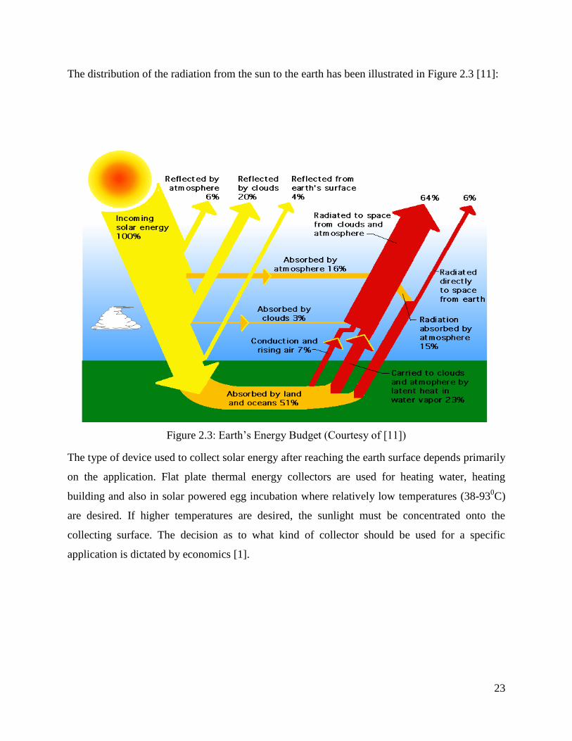
The distribution of the radiation from the sun to the earth has been illustrated in Figure 2.3 [11]:
Figure 2.3: Earth’s Energy Budget (Courtesy of [11])
The type of device used to collect solar energy after reaching the earth surface depends primarily
on the application. Flat plate thermal energy collectors are used for heating water, heating
building and also in solar powered egg incubation where relatively low temperatures (38-930C)
are desired. If higher temperatures are desired, the sunlight must be concentrated onto the
collecting surface. The decision as to what kind of collector should be used for a specific
application is dictated by economics [1].
24
2.2.2 Flat-Plate Solar Air Heaters [Collectors]
The solar collector is the essential item of equipment which transforms solar radiant energy to
some other useful energy form. A solar collector differs in several respects from more
convectional heat exchangers. The latter usually accomplish a fluid-fluid exchange with high
heat transfer rates and with radiation as an unimportant factor. In the solar collector, energy
transfer is from a distant source of radiant energy to a fluid. Without optical concentration, the
flux of incident radiation is, at best about 1100 W/m2 and is variable [1].
Solar energy is converted into thermal energy by use of solar collectors, which make use of the
greenhouse effect .The solar collection systems fall into two broad categories:
a) Concentrating collectors
b) Flat-plate collectors
Concentrating collectors collect the sun’s rays from a relatively large area and focus them on a
point. The collector makes use of parabolic (bowl-shaped) mirrors that can create extremely high
temperatures (over 10000C). But these temperatures are too high for egg incubation.
The concentrating collectors require precisely constructed surfaces and a tracking device to
follow the sun across the sky during the day. Due to this, they are relatively expensive and need
much maintenance.
The flat plate collector requires non tracking device to capture the sun’s energy and, absorbs
energy directly from the sun as well as indirect or diffuse radiation. They are capable of
providing temperatures of up to 65-930C, hence suitable for egg incubation and are relatively
simple to build [1].
There are many different designs for flat plate collectors, but they have two common features;
a) A flat plate to absorb energy from the sun.
b) A circulating medium to pick heat from the plate and transport to the storage or point of
use. The two media commonly used for absorbing and transferring the heat are air and
water but the latter has the disadvantage that it requires a pumping mechanism.
The use of a solar air heater is advantageous since, most parts of Kenya have plenty of sunshine.

25
The flat plate solar collector for heating air is simply a box insulated at the bottom and sides,
with one or more transparent covers made of glass or plastic in order to minimize heat loss to the
surroundings, but more than two covers are discouraged to eliminate shading effects. It also has
an absorber plate below the covers which in most cases is painted black and a plate below the
absorber plate. Between the glass covers, the absorber plate, and the black plate are insulation air
gaps or flow channels depending on the nature of the collector design and the purposed
application of the heated air.
For a two cover- plate collector, when solar irradiation strikes the outer cover, most irradiation
will be transmitted, reflected or absorbed. For a transparent cover, most of irradiation will be
transmitted. The transmitted energy is incident on the second cover where, it is mostly
transmitted to the absorber plate. The absorber plate heats up, there by transferring heat to the air
flowing over it.
2.2.2.1 Basic Components of a Flat Plate Collector
The important parts of a typical flat plate solar collector are:
A black flat plate which is covered by one or more transparent cover plate of glass or
plastic, and the sides and the bottom of the box are insulated.
A transparent cover where sunlight is transmitted through and absorbed by the black
surface beneath. The cover tends to reduce convection and radiation losses to the
atmosphere.
Thus, the black plate heats up and in turn heats a fluid flowing under, through, or over the plate.
The fluid can be either air or water. In this project, air was chosen.
26
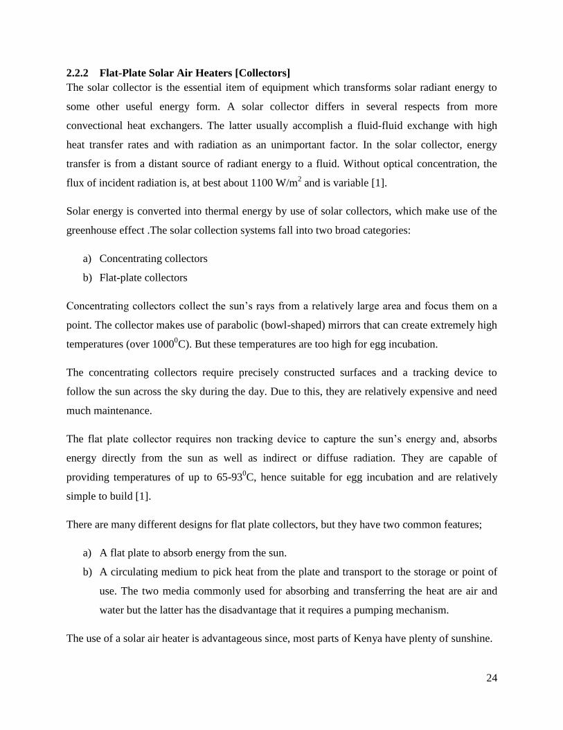
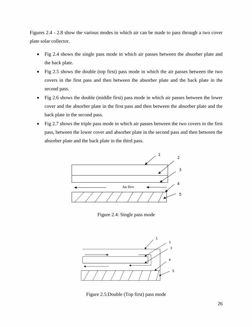
Figures 2.4 - 2.8 show the various modes in which air can be made to pass through a two cover
plate solar collector.
Fig 2.4 shows the single pass mode in which air passes between the absorber plate and
the back plate.
Fig 2.5 shows the double (top first) pass mode in which the air passes between the two
covers in the first pass and then between the absorber plate and the back plate in the
second pass.
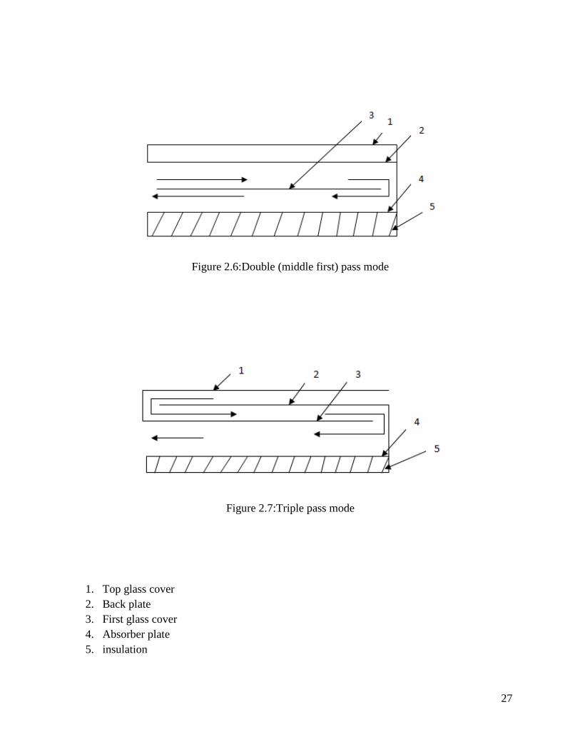
Fig 2.6 shows the double (middle first) pass mode in which air passes between the lower
cover and the absorber plate in the first pass and then between the absorber plate and the
back plate in the second pass.
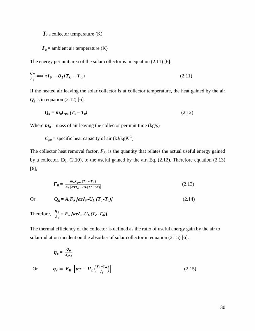
Fig 2.7 shows the triple pass mode in which air passes between the two covers in the first
pass, between the lower cover and absorber plate in the second pass and then between the
absorber plate and the back plate in the third pass.
Figure 2.4: Single pass mode
Figure 2.5:Double (Top first) pass mode
27
Figure 2.6:Double (middle first) pass mode
Figure 2.7:Triple pass mode
1. Top glass cover
2. Back plate
3. First glass cover
4. Absorber plate
5. insulation

28
2.2.2.2 Flat plate collector analysis
2.2.2.2.1 Solar incidence radiation on collector surface
The solar declination (d) is the angular distance of the sun’s rays north or south of the equator,
north declination being designated as positive. The declination of the sun for any day of the year
can be calculated using equation (2.2) [6].
d=23.47 *
( )+ (2.2)
Where angle is in degrees and N is the day of the year, numbering from January 1
The intensity of direct solar radiation (I) on a plane normal to the sun is calculated using
equation (2.3) [6].
I = G
(2.3)
Where G = apparent solar radiation at air mass zero (W/m2)
B = atmospheric extinction coefficient
a = solar altitude angle (degrees)
The solar altitude angle (a) is the angle between the sun’s rays and the horizontal surface
expressed as in equation (2.4) [6].
= 𝜹 + 𝜹 (2.4)
Where l is the latitude of a place on the surface of the earth
𝜹 is the angle of tilt of the flat plate collector.
h is the hour angle and is expressed as in equation (2.5) [6].
h =
T = 15 T (2.5)
Where T is the sun time before or after noon.

29
The direct radiation incident on a horizontal surface (Ih) is in equation (2.6) [6].
Ih = I (2.6)
The diffuse radiation (Id) is expressed by the following equation (2.7) [6].
Id = CIFss (2.7)
Where C = diffuse radiation factor
Fss = angle factor between the surface and the sky
The total solar radiation on a horizontal surface (It) is the sum of the direct radiation incident on
a horizontal surface (Ih) and the diffuse radiation (Id) in equation (2.8) [6].
It = Ih + Id (2.8)
The solar radiation at normal incidence on the plane of the collector surface tilted at an angle 𝜹
to the horizontal (Iδ) is in equation (2.9) [6]
Iδ =It 𝜹 ± It 𝜹 (2.9)
Where n is wall azimuth in degrees. A positive sign is used when the tilted surface faces the sun
and a negative sign is used when the collector is tilted away from the sun.
2.2.2.2.2 Energy gained by the solar collector
The energy gained by the solar collector can be expressed by the following equation (2.10) [6].
Qu = Iδ Ac – UL Ac (Tc-Ta) (2.10)
Where Ac = area of transparent cover (m2)
Iδ = total incident radiation on the collector surface (W/m2)
UL = overall heat loss for the collector (W/m2K
-1)
= solar absorptance
= transmittance
30
Tc = collector temperature (K)
Ta = ambient air temperature (K)
The energy per unit area of the solar collector is in equation (2.11) [6].
𝜹 ( ) (2.11)
If the heated air leaving the solar collector is at collector temperature, the heat gained by the air
Qg is in equation (2.12) [6].
Qg = aCpa (Tc – Ta) (2.12)
Where a = mass of air leaving the collector per unit time (kg/s)
Cpa = specific heat capacity of air (kJ/kgK-1
)
The collector heat removal factor, FR, is the quantity that relates the actual useful energy gained
by a collector, Eq. (2.10), to the useful gained by the air, Eq. (2.12). Therefore equation (2.13)
[6],
FR = ( – )
𝜹 ( – ) (2.13)
Or Qg = AcFR [ατIδ -UL (Tc -Ta)] (2.14)
Therefore,
= FR [ατIδ -UL (Tc -Ta)]
The thermal efficiency of the collector is defined as the ratio of useful energy gain by the air to
solar radiation incident on the absorber of solar collector in equation (2.15) [6]:
=
𝜹
Or * (
𝜹)+ (2.15)
31
2.2.2.2.3 Total heat requirement
The total heat requirement of the incubator (QT) is the summation of the heat energy required to
raise the temperature of air (Qa) and egg (Qe) from 30°C to 38.5°C; the heat loss through the wall
of the structure (Qs) and the heat loss by ventilation (Qv). Hence equation (2.16) [6],
QT= Qa + Qe + Qs + Qv (2.16)
The following relations were used to determine the heat requirements, equation (2.17), (2.18),
(2.19) and (2.20) [6]:
Qe = meCeΔT (2.17)
Qa = maCaΔT (2.18)
Qs =
(2.19)
Qv = ρVΔT (2.20)
Where, me = mass of eggs (kg)
ma = mass of air (kg)
Ce = specific heat capacity of egg (kJ/kgK-1
)
Ca = specific heat capacity of air (kJ/kgK-1
)
ΔT = temperature difference (K)
As = surface area of the incubator walls (m2)
Lwi = thickness of the incubator inner walls (m)
Lwo = thickness of the incubator outside walls (m)
Lins = insulation thickness (m)
kw = thermal conductivity of incubator walls (W/mK-1
)
32
kins= thermal conductivity of insulating materials (W/mK-1
)
ρa = density of air (kg/m3)
V= ventilation rate (m3/s)
2.2.3 Incubation
Incubation is the art of managing fertilized eggs to ensure the satisfactory development of
embryos into normal chicks either by natural or artificial methods. The egg is an extremely
specialized structure which contains sufficient food and water to develop a fertilized cell into a
chick if subjected to adequate environmental conditions.
2.2.3.1 Hatchability
This is the percentage of eggs set to hatch that in fact hatch. Several factors are known to affect
hatchability of eggs in the incubator. These include temperature and humidity control, conditions
of the egg, turning frequency and air supply and ventilation.
%Hatchability =
2.2.3.2 Care of hatching eggs
Before setting eggs in an incubator, quality fertile eggs should be obtained from a well-managed,
healthy flock fed on properly balanced diet. The following should be observed to ensure
hatchability of the eggs;
Collect the eggs early in the morning and frequently during the day to prevent excessive
chilling or heating of the eggs.
Do not wash eggs unless when necessary. If it is necessary to wash eggs, always use a
damp cloth with water warmer than the egg. This causes the egg to sweat the dirt out of
the pores. Never use water cooler than the egg. Also, do not soak the eggs in water. If the
egg is allowed to soak in water for a period of time, the temperature difference can
equalize and bacteria have a greater chance of entering through the pores. Be sure eggs
are dry before storing. Never place damp or wet eggs in a Styrofoam carton for storage.
Store the clean fertile eggs in an area which is kept at 130C – 19
0C and 70 – 75 %
humidity. Never store eggs at temperatures above 240C and at humidity lower than 40%.
33
These conditions can decrease hatchability dramatically in a very short period of time.
Slant or turn the fertile eggs daily while they are being stored. Do not store eggs for more
than 10-14 days. After 14 days of storage, hatchability begins to decline significantly.
Just before setting the eggs, allow them to warm to room temperature (21-27°C) and
remove any cracked eggs [12].
The environmental factors of major importance for an artificial incubator include:
a) Temperature.
The control of temperature is probably the most critical single factor required for the
successful hatching of chicks because developing embryos are extremely sensitive to
temperature of the environment. During the warm-up period, the temperature should be
adjusted to hold a constant 38°C for still air, 37-38°C for forced air [12].
Incubator temperature should be maintained between 37°C and 38°C. The acceptable
range is 36°C to 39°C. Mortality is seen if the temperature drops below 36°C or rises
above 39°C for a number of hours. If the temperature stays at either extreme for several
days, the eggs may not hatch. Overheating is more critical than under heating. Running
the incubator at 41°C for 15 minutes will seriously affect the embryos, while running it at
35°C for 3 or 4 hours will only slow the chick’s metabolic rate [12].
An incubator should be operated in a location free from drafts and direct sunlight. An
incubator should also be operated for several hours with water placed in a pan to stabilize
its internal atmosphere before fertile eggs are set. Do not adjust the heat upward during
the first 48 hours after eggs are set. This practice cooks many eggs. The eggs will take
time to warm to incubator temperature and many times in small incubators the incubator
temperature will drop below 37°C for the first 6-8 hours or until the egg warms to 37-
38°C [12].
34
b) Relative Humidity
The relative humidity of the air within an incubator should be about 60%. During the last
3 days (the hatching period) the relative humidity should be nearer 65-70 %.(Too much
moisture in the incubator prevents normal evaporation and results in a decreased hatch,
but excessive moisture is seldom a problem in small incubators.) Too little moisture
results in excessive evaporation, causing chicks to stick to the shell, remain in the pipped
shells, and sometimes hatch crippled [12].
During the hatching period, the humidity in the incubator may be increased by using an
atomizer to spray a small amount of water into the ventilating holes. (This is especially
helpful when duck or goose eggs are hatching.)
Whenever water is added to an incubator, it should be about the same temperature as the
incubator so that the eggs or the incubator are not stressed. A good test is to add water
just warm to the touch.
Using a wet-bulb thermometer is also a good way for determining relative humidity. The
wet-bulb thermometer measures the evaporative cooling effect. If the wet and dry bulb
read the same temperature, humidity is 100%. The greater the evaporation taking place,
the lower the temperature reading on the wet-bulb thermometer and the larger the spread
will be between the wet and dry-bulb readings. The range of wet bulb temperature
required is 26.5 - 32˚C [12].
To make a wet-bulb thermometer, add a cotton wick to the end of a thermometer. Then
place the tail of the wick to the end of a thermometer. Then place the tail of the wick in
water. The cotton then absorbs the water. As the water evaporates from the cotton it
causes a cooling effect on the thermometer.

35
Figure 2.8 shows an illustration of the wet bulb thermometer [13]:
Figure 2.8: wet bulb thermometer (Courtesy of [13])
c) Air Supply (Ventilation)
The best hatching results are obtained with normal atmospheric air, which usually
contains 20-21% oxygen. It is difficult to provide too much oxygen, but a deficiency is
possible. The ventilation holes are adjusted to allow a normal exchange of air.
This is critical on home-made incubators. It is possible to suffocate the eggs and chicks in
an air-tight container. However, excessive ventilation removes humidity and makes it
difficult to heat incubators properly.
36
CHAPTER 3
3 DATA ANALYSIS
3.1 Introduction
In this project, a solar poultry egg incubator was designed. The incubator consists of a solar
collector with built-in thermal storage and incubating chamber of 100 eggs capacity. It also has
air ducts for regulating heat flow from the solar collector to the incubating unit. A chimney was
located to the top centre of the incubating unit to ensure gases flow smoothly.
3.2 Assumptions
The design analysis of the solar collector in this project was based on the following assumptions
Collector performance is based on steady state conditions.
The temperature drop between the top and bottom of the absorber plate and glazing is
negligible.
Heat flow is one dimensional through the cover as well as through the back insulation.
Thermo physical properties of the materials are independent of temperature.
Heat losses from the top and bottom of the collector are to the same ambient temperature.
3.3 Preliminary Design
3.3.1 Capacity of the Incubator
This is needed to calculate the total power consumption needed by the system composed by the
incubator and any other element added to the system like fans, temperature and humidity meters.
Hence this incubator will have a capacity of 100 eggs.

37
3.3.2 Metrological Data
For a solar powered egg incubator, the positioning of the incubator has to be considered to get
the most energy from the sun. Ideally, with a 12-hour day and a 12-hour night, this is the
metrological data for Nairobi where the egg incubator will be located:
3.3.2.1 Solar Insolation of Nairobi
Average Insolation (10 year average): 5.62 kWh/m2/day [4].
3.3.2.2 Geographical Location of Nairobi [4]
Latitude: -1.29 (1°17'24"S)
Longitude: +36.82 (36°49'12"E)
Country: Kenya
Region : East Africa
Continent: Africa
Altitude: ~1700 m

38
Table 3.1 gives some Climatological information for Nairobi [4].
Table 3.1:Climatological Information (Courtesy of [4])
Month Mean Temperature (oC) Mean Total
Rainfall (mm)
Mean Number of Rain
Days Daily Minimum Daily Maximum
Jan 11.5 24.5 64.1 4
Feb 11.6 25.6 56.5 5
Mar 13.1 25.6 92.8 9
Apr 14.0 24.1 219.4 16
May 13.2 22.6 176.6 13
Jun 11.0 21.5 35.0 5
Jul 10.1 20.6 17.5 3
Aug 10.2 21.4 23.5 4
Sep 10.5 23.7 28.3 4
Oct 12.5 24.7 55.3 7
Nov 13.1 23.1 154.2 15
Dec 12.6 23.4 101.0 8

39
3.4 Design of the Collector
3.4.1 Description of the solar poultry egg Incubator
The solar poultry egg incubator designed is as in figure 3.1:
Figure 3.1: The Solar Poultry Egg Incubator
All dimensions in mm
1. Chimney, 2. Incubating cabinet, 3. Air outlet duct, 4. Transparent glass cover, 5. Air
inlet duct, 6. Cabinet door, 7. Stands, 8. Air flow regulator and 9. Solar collector
40
The equipment consists of a solar collector with built-in thermal storage unit, air ducts,
incubating unit and chimney.
3.4.2 Solar collector
The absorber plate of the solar collector is constructed using 2mm thick aluminium plate, painted
black with an absorptance, and is mounted in an outer box built from well-seasoned
soft wood (white pine) of thermal conductivity, k = 0.12 ⁄ .The 2mm thickness was
chosen so that the temperature drop between the top and the bottom of the absorber plate is
negligible. [14]
The space between the inner box and the outer box is filled with insulation material (fibre glass)
of thermal conductivity, ⁄ [14].
The inner box has two compartments; one is the air flow channel (the upper compartments) in
between the absorber plate and transparent top cover, and the other is the thermal storage unit
(lower compartment) in between the absorber plate and back plate. The overall length width and
height of the solar collector are [6].
The collector top glazing is a single layer transparent glass sheet of 4mm in thickness. The 4mm
was chosen since making it thinner will make it difficult to handle (fragile) and making it thicker
according to the law of radiation which states that the radiation going through will reduce as the
thickness increases. The glass sheet has a surface area of and a
transmittance of 0.7 for wavelengths in the range of 0.3 to 3µm [6].
3.4.3 The orientation of the solar collector
The solar collector is always fitted and oriented in such a way that it receives maximum solar
radiation during the desired season of use. In the analysis, an angle of orientation of solar
collector of 17˚C tilted horizontal was chosen. This is because with a flat plate collector, no
tracking of the sun is required. 17˚ is almost flat and creates a rather convenient gradient to
facilitate natural convection. It will also ensure that incase of moisture droplets forming on the
surface of the collector, they don’t flow into the incubation unit [6].
41
3.4.4 Solar incidence radiation on collector surface
The declination of the sun for any day of the year was calculated using equation (2.2):
A sample analysis was done for 27th
February 2012 which was the 58th
day of the year and the
mean temperature on this day was recorded as 23.1˚C, the annual mean temperature being
23.25˚C [4].
[
( )]
The hour angle was calculated using equation (2.5):
From the day used for analysis (27th
February 2012) T was found to be 46 minutes which was
hours = 0.77 [4].
Solar altitude angle (degrees) was calculated using equation (2.4):
For Nairobi, l was (117΄ 24"S)
This was equal to 1.29˚ [4].
- was the angle of tilt of the flat plane collector and for analysis was taken to be 17˚. This was
because with flat plane collector, there is no need to keep on tracking the sun and 17˚ is almost
flat and also created a gradient which facilitated free natural convection
( )
= ( ) ( ) ( ) ( ) ( )

42
The intensity of direct solar radiation I on a plane normal to the sun was calculated using
equation (2.3):
Typical values of B range from 0.20 to 0.27 and for analysis B was taken to be 0.235 for areas
near the equator [10].
G was taken to be ⁄ for regions that lie between equatorial and tropical regions [10].
⁄
=807.8 ⁄
The direct radiation ( ) incident on a horizontal surface was calculated using equation (2.6):
⁄
The diffuse radiation ( ) was calculated using equation (2.7):
C = diffuse radiation factor and is that portion of solar radiation that is scattered downwards by
the molecules in the atmosphere. During clear days, the magnitude of diffuse radiation factor is
about 10-14% of the total solar radiation received on the day. Since the collector is to operate
mostly when it’s a clear, C can be taken to be 12% = 0.12(the average of 10 to 14%) [10].
was calculated using;
⁄
The total solar radiation was calculated using equation (2.8);
⁄
43
The solar radiation at normal incidence on the plane of the collector surface tilted at an angle
to the horizontal was calculated using equation (2.9):
n = solar wall azimuth in degrees (a positive sign is used when the tilted surface faces the sun
and a negative sign is use when the collector is tilted away from the sun). It is often defined as
the angle from due north in a clockwise direction.
Since in the project, the collector was tilted at 17˚ towards the sun, a positive sign was used.
But
( ) ( )
( )
= ( ) ( )
⁄ . This is the radiation that reaches the collector.
3.4.5 Energy Gained by the Solar Collector
To obtain the energy gained by the solar collector, the overall heat loss coefficient for the
collector was determined using the analysis below:
The overall heat transfer coefficient was the result of convection and radiation between the
absorber plate and the glass cover. Hence [1]:
Where,
Furthermore: ( )(
)
[
]
Where; ( ⁄ )
= ⁄
44
[14]
( )( )
*
+
⁄
For the natural convection between parallel flat plate, the heat transfer coefficient, , was found
using an adaptation of Tabor’s graph as shown in Appendix 1. Air property convections
are plotted in Appendix 2. Mean
temperature of the collector plate =
C
Using were found to be 0.6 and 0.89 respectively.
Therefore;
But
= 9621.15
From the Tabor’s graph (appendix 1), using the value of and the curve marked H (the
collector plate was horizontal), was found to be 7.8 [1].
⁄
Finally,
⁄
45
The energy gained by the solar collector was calculated using equation (2.10):
For the design, the values were taken as [12]:
0.95
⁄
Hence
( )
= 258.25 W
⁄
Where
The heated air leaving the solar collector was at collector temperature, the heat gained by the air,
was calculated using equation (2.12):
Taking ⁄ then,
Cross-sectional area of air outlet duct was taken to be
The various properties of dry air at low pressure were determined using thermodynamic and
transport properties of fluids arranged by G.F.C Rogers and Y.R Mayhew.

46
At 23.25
= 1.0047kJ/kgK-1
= ⁄
= ⁄
( )
The collector heat removal factor was calculated using equation (2.13);
The thermal efficiency at the collector was defined as the ratio of useful energy gained by the air
to solar radiation on the absorber of the collector was calculated using equation (2.15);
=
The reason the thermal efficiency was low was due to;
The fact that the collector was using still air.
A thermal storage that was also absorbing heat.
3.4.6 Total heat requirement
The heat requirement of the incubator ( ) was calculated using equation (2.16):
The average mass of one egg was weighed and found to be 60g and the specific heat capacity of
the egg was taken to be 3.18 ⁄ [14].
Qe was calculated using equation (2.17):
( )
= 1621.8 J

47
The heat energy required for 100 eggs will be:
This is the total heat required to raise the temperature of the eggs from 30 to 38.5 . But this
heat was provided for gradually to avoid cooking the eggs. Usually a warming rate for incubation
is taken to be ⁄ [7].
So the time taken to raise the temperature of the eggs from 30 to 38.5 was found to be:
⁄ ⁄
Time taken = 3323.36 minutes
= 55.39 hours
= 2.3 days
was calculated using equation (2.18):
Taking ⁄
Using the steam tables, specific heat capacity air at 30˚C was found to be ⁄
( )
= 9.98W
was calculated using equation (2.19):
There is an outer and inner box built from galvanized sheet metal of In between
the wooden boxes is an insulation material (fibre glass) of [14].

48
Where:
Hence,
( )
Since there are 4 similar sides, the total was
6.98
was calculated using equation (2.20):
Where V = ventilation rate =
A suitable value of 4 air changes per hour was chosen [15].
The dimensions of the incubating unit are 584 × 784 × 784mm.
Therefore the volume of the incubating unit = 784
Therefore the ventilation rate =
V = 2.971
at 38.5˚C was found to be 1.135 ⁄ from steam tables
( )
= 9.98+0.8133+27.93+5.14
49
= 38.725W
According to the design, Qg was to provide energy during the day for the incubation unit. From
the analysis, was 54.89W while was 38.725W hence the design was viable.
3.5 Design of Incubator
3.5.1 Thermal storage unit
The thermal storage unit is a unit compartment that is located directly below the heat absorber
plate (figure 3.2). The following thermal storage materials which could be used in the thermal
storage unit were compared in terms of their thermo physical properties in table 3.2 [14]:
Table 3.2: Thermo physical properties of thermal storage materials (Courtesy of [14])
Material Brick Concrete Lime Sand Ballast
Thermal
Conductivity,
k(W/mK-1
)
0.731 0.721 0.731 0.721 0.725
Specific Heat
Capacity,
Cp(J/kgK-1
)
837 655.2 837 924 680-880
Density,
ρ(kg/m3)
1922 1858 1446 1601 2760-2770
From table 3.2, ballast was chosen as it was cheap and locally available. The thermal storage unit
contains ballast of 29mm average diameter.
The heat absorbed by the absorber plate is partially transmitted to the air flowing through the
conductor in the upper compartment and partially transmitted to the heat absorbing pebbles that
are loosely packed inside the lower compartment (storage unit). The ballast pebbles are loosely
packed to allow for thermal expansion.
Since the absorber plate is the source of heat for the rock pebbles, it is always at a higher
temperature than the pebbles during the sunshine hours. The ballast pebbles are being charged at
this period. During off sunshine hours when the absorber collector is collecting little or no
energy, the energy stored by the ballast pebbles is released and transmitted through the absorber

50
plate to the air flowing through the conductor. The length, width and height of the storage unit
are [6].
Figure 3.2 shows a cross sectional view of the thermal storage unit.
Figure 3.2: A Cross-sectional View of the Thermal Storage Unit
All dimensions are in mm
1. Heat absorber plate, 2. Transparent glass, 3. Air flow channel, 4. Inner Box, 5. Ballast
Pebbles, 6. Fibre glass, 7. Back plate, 8. Outer box
51
3.5.2 Thermal storage unit capacity
The amount of heat that can be stored by the ballast pebbles (Qb) was calculated as shown below:
= ( - )
Where = mass of the ballast pebbles (kg)
= specific heat capacity of the ballast pebbles (J/kgK-1
)
= ambient temperature (K)
= Temperature of the ballast directly beneath the absorber plate (K)
But
Where density of the ballast pebbles (kg/m3)
= volume occupied by the ballast pebbles (m3)
0.75 = Void factor to correct for calculation of [15]
Using the properties of ballast pebbles in table 4,
J/kgK
-1
kg/m
3
From the design, the length, width and height of the thermal storage unit were 1100mm, 600mm
and 200mm respectively.
= 0.132 m3
The ambient temperature (T1) was at 23.25 ˚C and the mean temperature (Tm) of the absorber
plate was at 46.625˚C. Assuming no heat loss between the absorber plate and the ballast pebbles
directly below then, T1 = Tm.
( )
52
On an average day, the sunshine hours are between 6 to 8 hours.
Time =
=7 hours
= 25200 seconds.
Therefore it will take 7 hours for the ballast pebbles to gain 4990.87 kJ. Hence the rate of heat
gained by the ballast pebbles is
= 198.05W
According to the design, the heat available for storage in the thermal storage unit is
258.25 – 38.725 = 219.525W
The difference between the two values can be accounted by the heat loss through the walls of the
thermal storage unit.
3.5.3 Air ducts
The lower end of the solar collector has an air inlet duct of in cross-
section, which is covered by a wire net to prevent entrance of rodents and insects. The upper end
of the solar collector also has a well lagged air outlet duct of in cross
section, which serves as a hot air passage from the solar collector to the incubating chamber.
Both ducts are located at the upper compartment of the solar collector.
A thermostatic air flow regulator is incorporated into the air outlet duct for the regulation of heat
flow from the solar collector to the incubating chamber.
3.5.4 Incubating unit
The incubating cabinet is made up of inner and outer boxes constructed from 2mm thick
galvanized sheet metal of thermal conductivity [14]. The 2mm thickness 30
gauge plate was chosen to make the structure lighter and also save on cost.
The external length and height of the outer box are while the
interior dimensions of the inner box are in the length, width and
height respectively [6].
The space between the inner and outer box is filled with fibre glass of about 40mm thick and
thermal conductivity of to reduce heat losses [14].
53
The inside of cabinet is painted silver white to minimize heat losses through absorption and
transmission through the walls to the atmosphere.
The door of the cabinet is made from similar materials. The interior part (incubating chamber) is
equipped with egg trays and an evaporative moisture pan to control relative humidity.
3.5.5 The chimney
It is located to the top center of the incubating unit. It has a square cross section of and a
height of It is constructed from thick galvanized iron sheets. It is covered by a
wire net to prevent entrance of rodents and insects [6].
3.5.6 Air circulation
The air circulation through the incubator is by natural convection. The cold (fresh) air that enters
through the collector inlet duct is heated by the solar radiation that falls on the collector, which
brings a temperature difference between the air at the lower and upper ends of the collector. The
temperature difference causes a density variation giving rise to buoyancy forces which in turn
causes the heated air to flow through the incubating chamber and pass through the chimney
without any pump. This type of fluid flow due to density gradient is usually termed natural flow.
3.6 Instrumentation and Controls
3.6.1 Thermostat
The control of temperature is probably the most critical single factor required for the successful
hatching of chicks because developing embryos are extremely sensitive to temperature of the
environment. Overheating speeds up the rate of development and causes abnormal embryos in
the early hatches and consequently lowers the percentage hatchability. During the warm-up
period, the temperature should be adjusted to hold a constant 38°C for still air, 37-38°C for
forced air [12].
In this project a thermostat was used to regulate the temperature in the incubating unit. The
thermostat was located in the upper end air duct between the solar collector and the incubating
unit. When the temperature in the incubating chamber increases to about 38.50c, the thermostat is
to switch off and shut the air duct so as to stop the hot air from the thermal storage unit from
flowing into the incubating chamber so that the temperature does not go past 38.5oc to avoid
cooking of the eggs. Similarly when the temperature falls below 35oc, the thermostat is to switch

54
on and start allowing hot air to pass to the incubating chamber since a lower temperature than
this will slow the chick’s metabolic rate [12].
A sample thermostat for use in incubation is shown in figure 3.3[13]:
Figure 3.3: A Sample Thermostat (Courtesy of [13])
3.6.2 Hygrometer
The relative humidity of the air within an incubator should be about 60%. During the last 3 days
(the hatching period) the relative humidity should be nearer 65-70 %. (Too much moisture in the
incubator prevents normal evaporation and results in a decreased hatch, but excessive moisture
are seldom a problem in small incubators.) Too little moisture results in excessive evaporation,
causing chicks to stick to the shell, remain in the pipped shells, and sometimes hatch crippled
[12].
The hygrometer is an easy to use tool for measuring the amount of humidity in the incubator.
The evaporative moisture pan in the incubating unit is used to provide the required humidity.
When the hygrometer readings exceeds 60% (except during the 3 days of the hatching period
when the relative humidity should be 65-70%), the evaporative moisture pan is removed from
the incubating unit. Similarly, when the hygrometer readings falls below 60%, the evaporative
moisture pan is returned [12].

55
A sample hygrometer for use in incubation is shown in figure 3.4 [13]:
Figure 3.4: A Sample Hygrometer (Courtesy of [13])
56
CHAPTER 4
4 DISCUSSION AND CONCLUSION
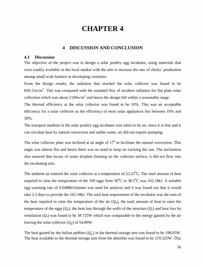
4.1 Discussion
The objective of the project was to design a solar poultry egg incubator, using materials that
were readily available in the local market with the aim to increase the rate of chicks’ production
among small scale farmers in developing countries.
From the design results, the radiation that reached the solar collector was found to be
830.15w/m2. This was compared with the standard flux of incident radiation for flat plate solar
collection which was about 1100w/m2 and hence the design fell within a reasonable range.
The thermal efficiency at the solar collector was found to be 10%. This was an acceptable
efficiency for a solar collector as the efficiency of most solar appliances lies between 10% and
30%.
The transport medium in the solar poultry egg incubator was taken to be air, since it is free and it
can circulate heat by natural convection and unlike water, air did not require pumping.
The solar collector plate was inclined at an angle of 170 to facilitate the natural convection. This
angle was almost flat and hence there was no need to keep on tracking the sun. The inclination
also ensured that incase of water droplets forming on the collector surface, it did not flow into
the incubating unit.
The ambient air entered the solar collector at a temperature of 23.250C. The total amount of heat
required to raise the temperature of the 100 eggs from 300C to 38.5
0C was 162.18kJ. A suitable
egg warming rate of 0.0488kJ/minute was used for analysis and it was found out that it would
take 2.3 days to provide the 162.18kJ. The total heat requirement of the incubator was the sum of
the heat required to raise the temperature of the air (Qa), the total amount of heat to raise the
temperature of the eggs (Qe), the heat loss through the walls of the structure (Qs) and heat loss by
ventilation (Qv) was found to be 38.725W which was comparable to the energy gained by the air
leaving the solar collector (Qg) of 54.89W.
The heat gained by the ballast pebbles ( ) in the thermal storage unit was found to be 198.05W.
The heat available to the thermal storage unit from the absorber was found to be 219.525W. This

57
meant that the thermal storage unit could supply the required energy to the incubating unit and
hence the ballast pebbles were a right choice for use as a thermal storage material.
The design results revealed a few facts that would form a good guideline in rating the
performance of a solar poultry egg incubator. From the results, further designs and
improvements could be made to arrive at a solar poultry egg incubator, that is not only very
efficient but can be made locally using locally available materials and be economically viable.
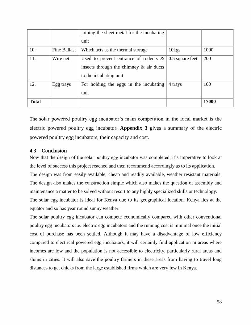
4.2 Cost Analysis
Table 4.1 shows the materials/instruments, its brief description, its size/capacity and its cost and
the total price to access the economic feasibility of the solar powered poultry egg incubator.
Table 4.1:Bill of Quantities
Number Item Description Size/Capacity Price(Ksh.)
1. Hygrometer Instrument to monitor humidity levels in
the incubating unit
1 2500
2. Thermostat Instrument to detect & control
temperature in the incubating unit
1 3000
3. Paint Black & Silver-white oil based paint for
the solar plate collector & incubator
inner-walls respectively
1 litre each 1200
4. Turpentine For thinning the paint 3 litres 1000
5. Galvanized
sheet metal
For constructing the incubator walls &
chimney
5 metre (30
gauge)
1500
6. Aluminium
sheet metal
For constructing the solar collector plate 2 mm thick
and 1.2 metre
length
700
7. Transparent
Glass
For the solar collector top glazing 4 mm and 10
square feet
700
8. Fibre Glass For insulation in the incubating unit &
storage unit
14 square feet 5000
9. Nails &
Rivets
For joining the soft pine to make the
wooden boxes of the storage unit &
2" ¼ kg each 100
58
joining the sheet metal for the incubating
unit
10. Fine Ballast Which acts as the thermal storage 10kgs 1000
11. Wire net Used to prevent entrance of rodents &
insects through the chimney & air ducts
to the incubating unit
0.5 square feet 200
12. Egg trays For holding the eggs in the incubating
unit
4 trays 100
Total 17000
The solar powered poultry egg incubator’s main competition in the local market is the
electric powered poultry egg incubator. Appendix 3 gives a summary of the electric
powered poultry egg incubators, their capacity and cost.
4.3 Conclusion
Now that the design of the solar poultry egg incubator was completed, it’s imperative to look at
the level of success this project reached and then recommend accordingly as to its application.
The design was from easily available, cheap and readily available, weather resistant materials.
The design also makes the construction simple which also makes the question of assembly and
maintenance a matter to be solved without resort to any highly specialized skills or technology.
The solar egg incubator is ideal for Kenya due to its geographical location. Kenya lies at the
equator and so has year round sunny weather.
The solar poultry egg incubator can compete economically compared with other conventional
poultry egg incubators i.e. electric egg incubators and the running cost is minimal once the initial
cost of purchase has been settled. Although it may have a disadvantage of low efficiency
compared to electrical powered egg incubators, it will certainly find application in areas where
incomes are low and the population is not accessible to electricity, particularly rural areas and
slums in cities. It will also save the poultry farmers in these areas from having to travel long
distances to get chicks from the large established firms which are very few in Kenya.

59
4.4 Recommendations
Raising the thermal efficiency of the solar collector from 10%.
Fabrication and testing of the design.
A turning mechanism for the eggs which can run on solar power without interfering with
the prevailing conditions in the incubating unit.
A more suitable means of raising the humidity in the incubating unit rather than the
evaporative moisture pan.
The effect of the black paint layer on the solar collector plate when calculating the overall
heat transfer coefficient (Ul).
60
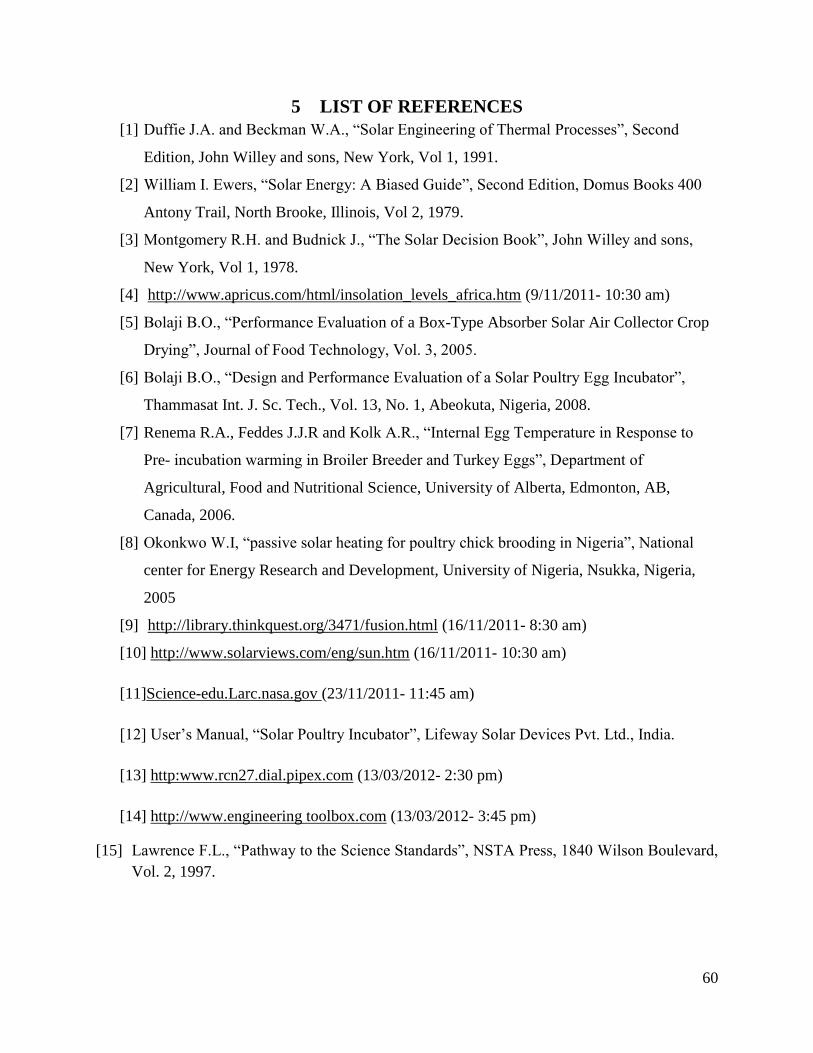
5 LIST OF REFERENCES
[1] Duffie J.A. and Beckman W.A., “Solar Engineering of Thermal Processes”, Second
Edition, John Willey and sons, New York, Vol 1, 1991.
[2] William I. Ewers, “Solar Energy: A Biased Guide”, Second Edition, Domus Books 400
Antony Trail, North Brooke, Illinois, Vol 2, 1979.
[3] Montgomery R.H. and Budnick J., “The Solar Decision Book”, John Willey and sons,
New York, Vol 1, 1978.
[4] http://www.apricus.com/html/insolation_levels_africa.htm (9/11/2011- 10:30 am)
[5] Bolaji B.O., “Performance Evaluation of a Box-Type Absorber Solar Air Collector Crop
Drying”, Journal of Food Technology, Vol. 3, 2005.
[6] Bolaji B.O., “Design and Performance Evaluation of a Solar Poultry Egg Incubator”,
Thammasat Int. J. Sc. Tech., Vol. 13, No. 1, Abeokuta, Nigeria, 2008.
[7] Renema R.A., Feddes J.J.R and Kolk A.R., “Internal Egg Temperature in Response to
Pre- incubation warming in Broiler Breeder and Turkey Eggs”, Department of
Agricultural, Food and Nutritional Science, University of Alberta, Edmonton, AB,
Canada, 2006.
[8] Okonkwo W.I, “passive solar heating for poultry chick brooding in Nigeria”, National
center for Energy Research and Development, University of Nigeria, Nsukka, Nigeria,
2005
[9] http://library.thinkquest.org/3471/fusion.html (16/11/2011- 8:30 am)
[10] http://www.solarviews.com/eng/sun.htm (16/11/2011- 10:30 am)
[11]Science-edu.Larc.nasa.gov (23/11/2011- 11:45 am)
[12] User’s Manual, “Solar Poultry Incubator”, Lifeway Solar Devices Pvt. Ltd., India.
[13] http:www.rcn27.dial.pipex.com (13/03/2012- 2:30 pm)
[14] http://www.engineering toolbox.com (13/03/2012- 3:45 pm)
[15] Lawrence F.L., “Pathway to the Science Standards”, NSTA Press, 1840 Wilson Boulevard,
Vol. 2, 1997.