University of Jordan Faculty of Engineering & Technology...
101
Prepared By: Eng.Alaa Arabiyat, Eng.Balqees Al-Shagoor Page 1 of 13 University of Jordan Faculty of Engineering & Technology Computer Engineering Department Advance Networks Laboratory 0907529 Exp.1 Access Control Lists (ACLs) Objectives 1. Explain how ACLs are used to filter traffic. 2. Compare standard and extended IPv4 ACLs. 3. Explain the guidelines for creating and placement of ACLs. 4. Modify ACLs. 5. Explain how a router processes packets when an ACL is applied. 6. Troubleshoot common ACL errors. 1. Purpose of ACLs: Network security is a huge subject, and one of the most important skills a network administrator needs is mastery of access control lists (ACLs). Network designers use firewalls to protect networks from unauthorized use. Firewalls are hardware or software solutions that enforce network security policies. Consider a lock on a door to a room inside a building. The lock allows only authorized users with a key or access card to pass through the door. Similarly, a firewall filters unauthorized or potentially dangerous packets from entering the network. On a Cisco router, you can configure a simple firewall that provides basic traffic filtering capabilities using ACLs. Administrators use ACLs to stop traffic or permit only specified traffic on their networks. An ACL is a sequential list of permit or deny statements that apply to addresses or upper-layer protocols based on information found in the packet header. ACLs provide a powerful way to control traffic into and out of a network. ACLs can be configured for all routed network protocols. When configured, ACLs perform the following tasks as shown in the figure below: Limit network traffic to increase network performance. For example, if corporate policy does not allow video traffic on the network, ACLs that block video traffic could be configured and applied. This would greatly reduce the network load and increase network performance. Provide traffic flow control. ACLs can restrict the delivery of routing updates. If updates are not required because of network conditions, bandwidth is preserved. Provide a basic level of security for network access. ACLs can allow one host to access a part of the network and prevent another host from accessing the same area. For example, access to the Human Resources network can be restricted to authorized users. Filter traffic based on traffic type. For example, an ACL can permit email traffic, but block all Telnet traffic. Screen hosts to permit or deny access to network services. ACLs can permit or deny a user to access file types, such as FTP or HTTP.
Transcript of University of Jordan Faculty of Engineering & Technology...

Prepared By: Eng.Alaa Arabiyat, Eng.Balqees Al-Shagoor Page 1 of 13
University of Jordan
Faculty of Engineering & Technology
Computer Engineering Department
Advance Networks Laboratory 0907529
Exp.1 Access Control Lists (ACLs)
Objectives 1. Explain how ACLs are used to filter traffic.
2. Compare standard and extended IPv4 ACLs.
3. Explain the guidelines for creating and placement of ACLs.
4. Modify ACLs.
5. Explain how a router processes packets when an ACL is applied.
6. Troubleshoot common ACL errors.
1. Purpose of ACLs:
Network security is a huge subject, and one of the most important skills a network administrator
needs is mastery of access control lists (ACLs).
Network designers use firewalls to protect networks from unauthorized use. Firewalls are
hardware or software solutions that enforce network security policies. Consider a lock on a door
to a room inside a building. The lock allows only authorized users with a key or access card to
pass through the door. Similarly, a firewall filters unauthorized or potentially dangerous packets
from entering the network. On a Cisco router, you can configure a simple firewall that provides
basic traffic filtering capabilities using ACLs. Administrators use ACLs to stop traffic or permit
only specified traffic on their networks.
An ACL is a sequential list of permit or deny statements that apply to addresses or upper-layer
protocols based on information found in the packet header. ACLs provide a powerful way to
control traffic into and out of a network. ACLs can be configured for all routed network
protocols.
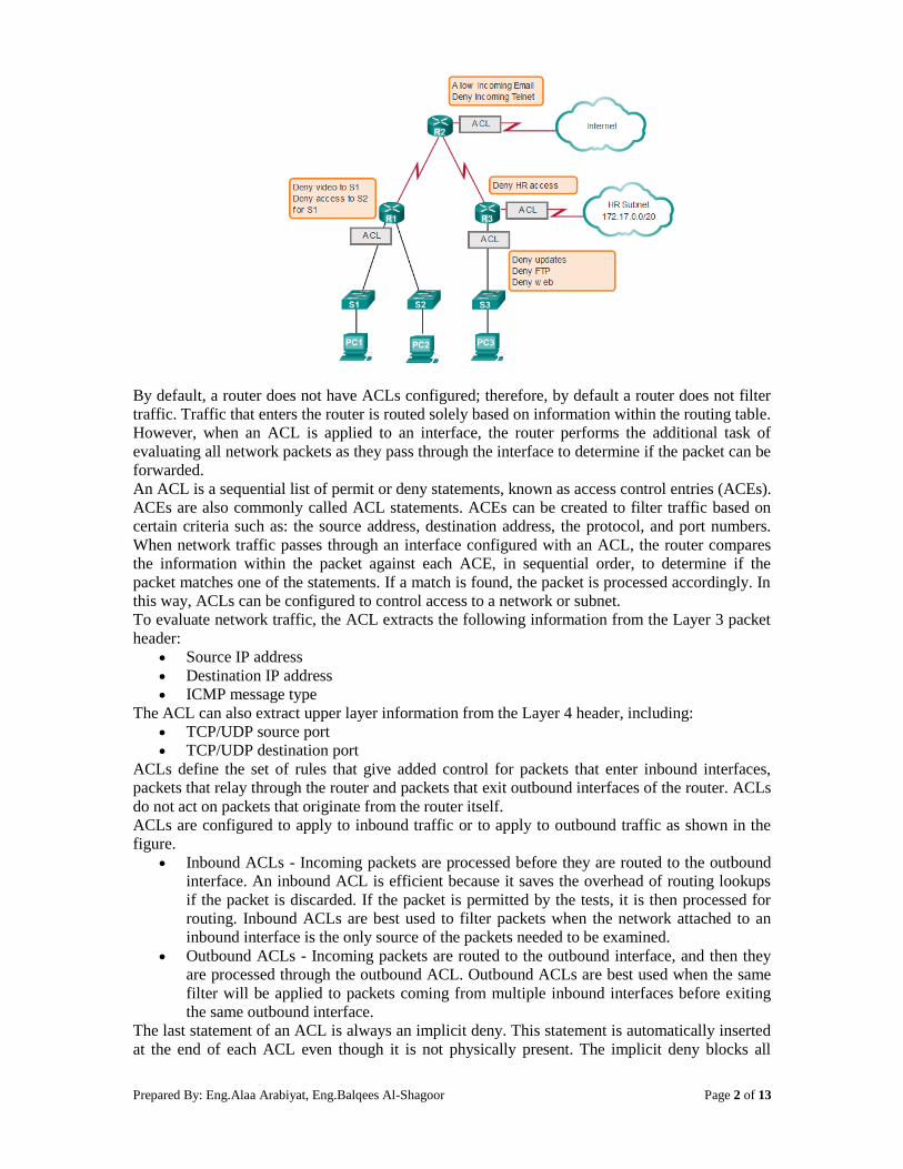
When configured, ACLs perform the following tasks as shown in the figure below:
Limit network traffic to increase network performance. For example, if corporate policy
does not allow video traffic on the network, ACLs that block video traffic could be
configured and applied. This would greatly reduce the network load and increase network
performance.
Provide traffic flow control. ACLs can restrict the delivery of routing updates. If updates
are not required because of network conditions, bandwidth is preserved.
Provide a basic level of security for network access. ACLs can allow one host to access a
part of the network and prevent another host from accessing the same area. For example,
access to the Human Resources network can be restricted to authorized users.
Filter traffic based on traffic type. For example, an ACL can permit email traffic, but
block all Telnet traffic.
Screen hosts to permit or deny access to network services. ACLs can permit or deny a
user to access file types, such as FTP or HTTP.

Prepared By: Eng.Alaa Arabiyat, Eng.Balqees Al-Shagoor Page 2 of 13
By default, a router does not have ACLs configured; therefore, by default a router does not filter
traffic. Traffic that enters the router is routed solely based on information within the routing table.
However, when an ACL is applied to an interface, the router performs the additional task of
evaluating all network packets as they pass through the interface to determine if the packet can be
forwarded.
An ACL is a sequential list of permit or deny statements, known as access control entries (ACEs).
ACEs are also commonly called ACL statements. ACEs can be created to filter traffic based on
certain criteria such as: the source address, destination address, the protocol, and port numbers.
When network traffic passes through an interface configured with an ACL, the router compares
the information within the packet against each ACE, in sequential order, to determine if the
packet matches one of the statements. If a match is found, the packet is processed accordingly. In
this way, ACLs can be configured to control access to a network or subnet.
To evaluate network traffic, the ACL extracts the following information from the Layer 3 packet
header:
Source IP address
Destination IP address
ICMP message type
The ACL can also extract upper layer information from the Layer 4 header, including:
TCP/UDP source port
TCP/UDP destination port
ACLs define the set of rules that give added control for packets that enter inbound interfaces,
packets that relay through the router and packets that exit outbound interfaces of the router. ACLs
do not act on packets that originate from the router itself.
ACLs are configured to apply to inbound traffic or to apply to outbound traffic as shown in the
figure.
Inbound ACLs - Incoming packets are processed before they are routed to the outbound
interface. An inbound ACL is efficient because it saves the overhead of routing lookups
if the packet is discarded. If the packet is permitted by the tests, it is then processed for
routing. Inbound ACLs are best used to filter packets when the network attached to an
inbound interface is the only source of the packets needed to be examined.
Outbound ACLs - Incoming packets are routed to the outbound interface, and then they
are processed through the outbound ACL. Outbound ACLs are best used when the same
filter will be applied to packets coming from multiple inbound interfaces before exiting
the same outbound interface.
The last statement of an ACL is always an implicit deny. This statement is automatically inserted
at the end of each ACL even though it is not physically present. The implicit deny blocks all

Prepared By: Eng.Alaa Arabiyat, Eng.Balqees Al-Shagoor Page 3 of 13
traffic. Because of this implicit deny, an ACL that does not have at least one permit statement
will block all traffic.
2. Standard versus Extended IPv4 ACLs:
The two types of Cisco IPv4 ACLs are standard and extended. Standard ACLs can be used to
permit or deny traffic only from source IPv4 addresses. The destination of the packet and the
ports involved are not evaluated. The example below allows all traffic from the 192.168.30.0/24
network. Because of the implied "deny any" at the end, all other traffic is blocked with this ACL.
Standard ACLs are created in global configuration mode.
R1(config)# access-list 10 permit 192.168.30.0 0.0.0.255
Extended ACLs filter IPv4 packets based on several attributes:
Protocol type
Source IPv4 address
Destination IPv4 address
Source TCP or UDP ports
Destination TCP or UDP ports
In the example below, ACL 103 permits traffic originating from any address on the
192.168.30.0/24 network to any IPv4 network if the destination host port is 80 (HTTP). Extended
ACLs are created in global configuration mode.
R1(config)# access-list 103 permit tcp 192.168.30.0 0.0.0.255 any eq80
The commands for standard and extended ACLs are explained in more details later in this
experiment.
Standard and extended ACLs can be created using either a number or a name to identify the ACL
and its list of statements. Using numbered ACLs is an effective method for determining the ACL
type on smaller networks with more homogeneously defined traffic. However, a number does not
provide information about the purpose of the ACL.
Numbered ACL: Assign a number based on protocol to be filtered.
(1 to 99) and (1300 to 1999): Standard IP ACL
(100 to 199) and (2000 to 2699): Extended IP ACL
Named ACL: Assign a name to identify the ACL.
Names can contain alphanumeric characters.
It is suggested that the name be written in CAPITAL LETTERS.
Names cannot contain spaces or punctuation.
Entries can be added or deleted within the ACL.
Writing ACLs can be a complex task. For every interface there may be multiple policies needed
to manage the type of traffic allowed to enter or exit that interface. The router in the figure has
two interfaces configured for IPv4 and IPv6. If we needed ACLs for both protocols, on both
interfaces and in both directions, this would require eight separate ACLs. Each interface would
have four ACLs; two ACLs for IPv4 and two ACLs for IPv6. For each protocol, one ACL is for
inbound traffic and one for outbound traffic.
The Three Ps:
A general rule for applying ACLs on a router can be recalled by remembering the three Ps. You
can configure one ACL per protocol, per direction, per interface:
One ACL per protocol - To control traffic flow on an interface, an ACL must be defined
for each protocol enabled on the interface.
One ACL per direction - ACLs control traffic in one direction at a time on an interface.
Two separate ACLs must be created to control inbound and outbound traffic.

Prepared By: Eng.Alaa Arabiyat, Eng.Balqees Al-Shagoor Page 4 of 13
One ACL per interface - ACLs control traffic for an interface, for example,
GigabitEthernet 0/0.
The proper placement of an ACL can make the network operate more efficiently. An ACL can be
placed to reduce unnecessary traffic. For example, traffic that will be denied at a remote
destination should not be forwarded using network resources along the route to that destination.
Every ACL should be placed where it has the greatest impact on efficiency. As shown in the
figure below, the basic rules are:
Extended ACLs - Locate extended ACLs as close as possible to the source of the traffic
to be filtered. This way, undesirable traffic is denied close to the source network without
crossing the network infrastructure.
Standard ACLs - Because standard ACLs do not specify destination addresses, place
them as close to the destination as possible. Placing a standard ACL at the source of the
traffic will effectively prevent that traffic from reaching any other networks through the
interface where the ACL is applied.
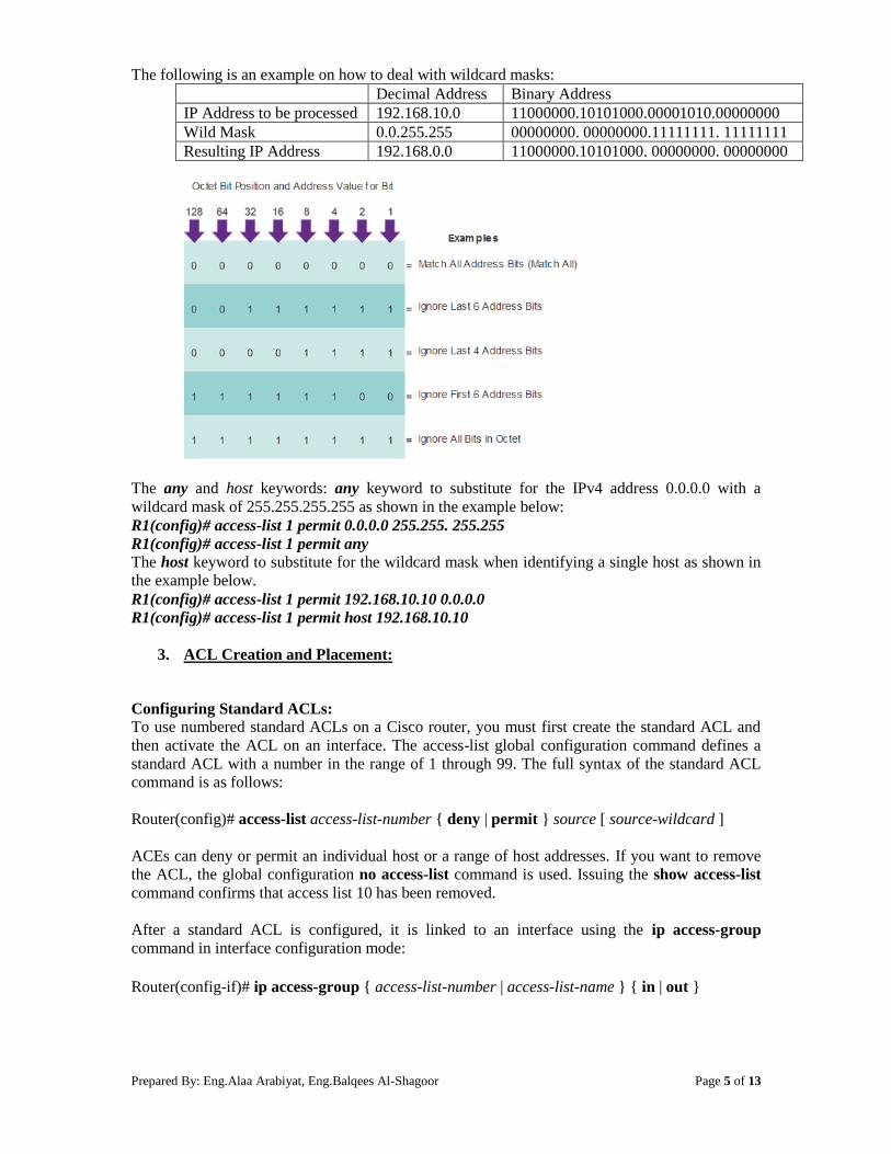
Wildcard Masks in ACLs
IPv4 ACEs include the use of wildcard masks. A wildcard mask is a string of 32 binary digits
used by the router to determine which bits of the address to examine for a match.
Subnet masks use binary 1s and 0s to identify the network, subnet, and host portion of an IP
address. Wildcard masks use binary 1s and 0s to filter individual IP addresses or groups of IP
addresses to permit or deny access to resources.
Wildcard masks and subnet masks differ in the way they match binary 1s and 0s. Wildcard masks
use the following rules to match binary 1s and 0s:
Wildcard mask bit 0 - Match the corresponding bit value in the address.
Wildcard mask bit 1 - Ignore the corresponding bit value in the address.
Prepared By: Eng.Alaa Arabiyat, Eng.Balqees Al-Shagoor Page 5 of 13
The following is an example on how to deal with wildcard masks:
Decimal Address Binary Address
IP Address to be processed 192.168.10.0 11000000.10101000.00001010.00000000
Wild Mask 0.0.255.255 00000000. 00000000.11111111. 11111111
Resulting IP Address 192.168.0.0 11000000.10101000. 00000000. 00000000
The any and host keywords: any keyword to substitute for the IPv4 address 0.0.0.0 with a
wildcard mask of 255.255.255.255 as shown in the example below:
R1(config)# access-list 1 permit 0.0.0.0 255.255. 255.255
R1(config)# access-list 1 permit any
The host keyword to substitute for the wildcard mask when identifying a single host as shown in
the example below.
R1(config)# access-list 1 permit 192.168.10.10 0.0.0.0
R1(config)# access-list 1 permit host 192.168.10.10
3. ACL Creation and Placement:
Configuring Standard ACLs:
To use numbered standard ACLs on a Cisco router, you must first create the standard ACL and
then activate the ACL on an interface. The access-list global configuration command defines a
standard ACL with a number in the range of 1 through 99. The full syntax of the standard ACL
command is as follows:
Router(config)# access-list access-list-number { deny | permit } source [ source-wildcard ]
ACEs can deny or permit an individual host or a range of host addresses. If you want to remove
the ACL, the global configuration no access-list command is used. Issuing the show access-list
command confirms that access list 10 has been removed.
After a standard ACL is configured, it is linked to an interface using the ip access-group
command in interface configuration mode:
Router(config-if)# ip access-group { access-list-number | access-list-name } { in | out }

Prepared By: Eng.Alaa Arabiyat, Eng.Balqees Al-Shagoor Page 6 of 13
To remove an ACL from an interface, first enter the no ip access-group command on the
interface, and then enter the global no access-list command to remove the entire ACL.
To create a statement that will permit a range of IPv4 addresses in a numbered ACL 10 that
permits all IPv4 addresses in the network 192.168.10.0/24, you would enter:
R1(config)# access-list 10 permit 192.168.10.10 0.0.0.255
To apply a numbered standard ACL 10 on a router, you would enter:
R1(config)#interface serial 0/0/0
R1(config-if)# ip access-group 10 out
This ACL allows only traffic from source network 192.168.10.0 to be forwarded out of interface
S0/0/0. Traffic from networks other than 192.168.10.0 is blocked.
Naming an ACL makes it easier to understand its function. For example, the above ACL could be
called VLAN10_ALLOW. When you identify your ACL with a name instead of with a number,
the configuration mode and command syntax are slightly different as shown below.
R1(config)# ip access-list standard VLAN10_ALLOW
R1(config-std-nacl)# permit 192.168.10.10 0.0.0.255
R1(config-std-nacl)#exit
R1(config)#interface serial 0/0/0
R1(config-if)# ip access-group VLAN10_ALLOW out
Using an ACL to Control VTY Access:
Restricting VTY access is a technique that allows you to define which IP addresses are allowed
Telnet access to the router EXEC process. You can control which administrative workstation or
network manages your router with an ACL and an access-class statement configured on your
VTY lines.
An example allowing a range of addresses to access VTY lines 0 - 4 is shown below.
Configure the vty lines to accept incoming telnet connections using access list 21.
R1(config)# line vty 0 4
R1(config-line)# access-class 21 in
Create access list 21 to permit the 192.168.10.0/24 network to access VTY lines 0 - 4 and
explicitly deny all others.
R1(config)# access-list 21 permit 192.168.10.0 0.0.0.255
R1(config)# access-list 21 deny any
Prepared By: Eng.Alaa Arabiyat, Eng.Balqees Al-Shagoor Page 7 of 13
Configuring Extended ACLs:
The procedural steps for configuring extended ACLs are the same as for standard ACLs. The
extended ACL is first configured, and then it is activated on an interface. However, the command
syntax and parameters are more complex to support the additional features provided by extended
ACLs. The common command syntax for extended IPv4 ACLs is shown below. Note that there
are many keywords and parameters for extended ACLs. It is not necessary to use all of the
keywords and parameters when configuring an extended ACL.
Router(config)# access-list access-list-number { deny | permit } protocol source [ source-
wildcard ] [port port-number or name] destination [destination-wildcard] [port port-number or
name] [established]
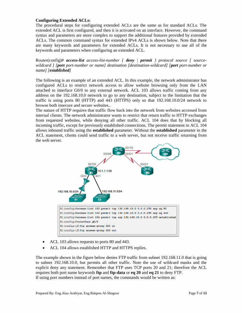
The following is an example of an extended ACL. In this example, the network administrator has
configured ACLs to restrict network access to allow website browsing only from the LAN
attached to interface G0/0 to any external network. ACL 103 allows traffic coming from any
address on the 192.168.10.0 network to go to any destination, subject to the limitation that the
traffic is using ports 80 (HTTP) and 443 (HTTPS) only so that 192.168.10.0/24 network to
browse both insecure and secure websites..
The nature of HTTP requires that traffic flow back into the network from websites accessed from
internal clients. The network administrator wants to restrict that return traffic to HTTP exchanges
from requested websites, while denying all other traffic. ACL 104 does that by blocking all
incoming traffic, except for previously established connections. The permit statement in ACL 104
allows inbound traffic using the established parameter. Without the established parameter in the
ACL statement, clients could send traffic to a web server, but not receive traffic returning from
the web server.
ACL 103 allows requests to ports 80 and 443.
ACL 104 allows established HTTP and HTTPS replies.
The example shown in the figure below denies FTP traffic from subnet 192.168.11.0 that is going
to subnet 192.168.10.0, but permits all other traffic. Note the use of wildcard masks and the
explicit deny any statement. Remember that FTP uses TCP ports 20 and 21; therefore the ACL
requires both port name keywords ftp and ftp-data or eq 20 and eq 21 to deny FTP.
If using port numbers instead of port names, the commands would be written as:

Prepared By: Eng.Alaa Arabiyat, Eng.Balqees Al-Shagoor Page 8 of 13
access-list 114 permit tcp 192.168.20.0 0.0.0.255 any eq 20
access-list 114 permit tcp 192.168.20.0 0.0.0.255 any eq 21 To prevent the implied deny any statement at the end of the ACL from blocking all traffic, the
permit ip any any statement is added. Without at least one permit statement in an ACL, all
traffic on the interface where that ACL was applied would be dropped. The ACL should be
applied inbound on the G0/1 interface so that traffic from the 192.168.11.0/24 LAN is filtered as
it enters the router interface.
Named extended ACLs are created in essentially the same way that named standard ACLs are
created. The figure below shows the named versions of the ACLs created in a previous example.
4. Modify ACLs.
Editing an extended ACL can be accomplished using the same process as editing a standard ACL.
An ACL can be modified using:
Prepared By: Eng.Alaa Arabiyat, Eng.Balqees Al-Shagoor Page 9 of 13
Method 1 Text editor - Using this method, the ACL is copied and pasted into the text
editor where the changes are made. The current access list is removed using the no
access-list command. The modified ACL is then pasted back into the configuration.
Method 2 Sequence numbers - Sequence numbers can be used to delete or insert an
ACL statement. The ip access-list {standard | extended} name command is used to
enter named-ACL configuration mode. If the ACL is numbered instead of named, the
ACL number is used in the name parameter. ACEs can be inserted or removed.
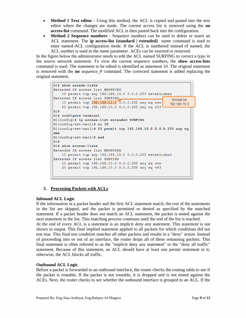
In the figure below the administrator needs to edit the ACL named SURFING to correct a typo in
the source network statement. To view the current sequence numbers, the show access-lists
command is used. The statement to be edited is identified as statement 10. The original statement
is removed with the no sequence_# command. The corrected statement is added replacing the
original statement.
5. Processing Packets with ACLs
Inbound ACL Logic If the information in a packet header and the first ACL statement match, the rest of the statements
in the list are skipped, and the packet is permitted or denied as specified by the matched
statement. If a packet header does not match an ACL statement, the packet is tested against the
next statement in the list. This matching process continues until the end of the list is reached.
At the end of every ACL is a statement is an implicit deny any statement. This statement is not
shown in output. This final implied statement applied to all packets for which conditions did not
test true. This final test condition matches all other packets and results in a "deny" action. Instead
of proceeding into or out of an interface, the router drops all of these remaining packets. This
final statement is often referred to as the "implicit deny any statement" or the "deny all traffic"
statement. Because of this statement, an ACL should have at least one permit statement in it;
otherwise, the ACL blocks all traffic.
Outbound ACL Logic Before a packet is forwarded to an outbound interface, the router checks the routing table to see if
the packet is routable. If the packet is not routable, it is dropped and is not tested against the
ACEs. Next, the router checks to see whether the outbound interface is grouped to an ACL. If the

Prepared By: Eng.Alaa Arabiyat, Eng.Balqees Al-Shagoor Page 10 of 13
outbound interface is not grouped to an ACL, the packet can be sent to the output buffer.
Examples of outbound ACL operation are as follows:
No ACL applied to the interface: If the outbound interface is not grouped to an
outbound ACL, the packet is sent directly to the outbound interface.
ACL applied to the interface: If the outbound interface is grouped to an outbound ACL,
the packet is not sent out on the outbound interface until it is tested by the combination of
ACEs that are associated with that interface. Based on the ACL tests, the packet is
permitted or denied.
For outbound lists, "permit" means to send the packet to the output buffer, and "deny" means to
discard the packet.
6. Troubleshoot ACLs
Using the show commands reveals most of the more common ACL errors. The most common
errors are entering ACEs in the wrong order and not applying adequate criteria to the ACL rules.
Error Example 1 In the figure below, host 192.168.10.10 has no connectivity with 192.168.30.12. When viewing
the output of the show access-lists command, matches are shown for the first deny statement.
This is an indicator that this statement has been matched by traffic.
Solution - Look at the order of the ACEs (ACL Entries). Host 192.168.10.10 has no connectivity
with 192.168.30.12 because of the order of rule 10 in the access list. Because the router processes
ACLs from the top down, statement 10 denies host 192.168.10.10, so statement 20 can never be
matched. Statements 10 and 20 should be reversed. The last line allows all other non-TCP traffic
that falls under IP (ICMP, UDP, etc.).

Prepared By: Eng.Alaa Arabiyat, Eng.Balqees Al-Shagoor Page 11 of 13
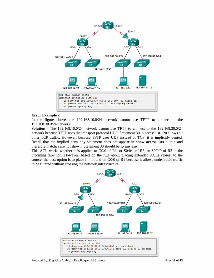
Error Example 2 In the figure above, the 192.168.10.0/24 network cannot use TFTP to connect to the
192.168.30.0/24 network.
Solution - The 192.168.10.0/24 network cannot use TFTP to connect to the 192.168.30.0/24
network because TFTP uses the transport protocol UDP. Statement 30 in access list 120 allows all
other TCP traffic. However, because TFTP uses UDP instead of TCP, it is implicitly denied.
Recall that the implied deny any statement does not appear in show access-lists output and
therefore matches are not shown. Statement 30 should be ip any any.
This ACL works whether it is applied to G0/0 of R1, or S0/0/1 of R3, or S0/0/0 of R2 in the
incoming direction. However, based on the rule about placing extended ACLs closest to the
source, the best option is to place it inbound on G0/0 of R1 because it allows undesirable traffic
to be filtered without crossing the network infrastructure.
Prepared By: Eng.Alaa Arabiyat, Eng.Balqees Al-Shagoor Page 12 of 13
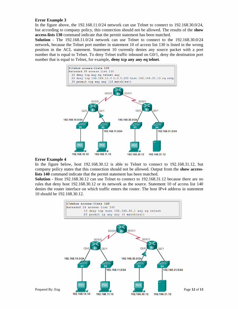
Error Example 3 In the figure above, the 192.168.11.0/24 network can use Telnet to connect to 192.168.30.0/24,
but according to company policy, this connection should not be allowed. The results of the show
access-lists 130 command indicate that the permit statement has been matched.
Solution - The 192.168.11.0/24 network can use Telnet to connect to the 192.168.30.0/24
network, because the Telnet port number in statement 10 of access list 130 is listed in the wrong
position in the ACL statement. Statement 10 currently denies any source packet with a port
number that is equal to Telnet. To deny Telnet traffic inbound on G0/1, deny the destination port
number that is equal to Telnet, for example, deny tcp any any eq telnet.
Error Example 4 In the figure below, host 192.168.30.12 is able to Telnet to connect to 192.168.31.12, but
company policy states that this connection should not be allowed. Output from the show access-
lists 140 command indicate that the permit statement has been matched.
Solution - Host 192.168.30.12 can use Telnet to connect to 192.168.31.12 because there are no
rules that deny host 192.168.30.12 or its network as the source. Statement 10 of access list 140
denies the router interface on which traffic enters the router. The host IPv4 address in statement
10 should be 192.168.30.12.
Prepared By: Eng.Alaa Arabiyat, Eng.Balqees Al-Shagoor Page 13 of 13
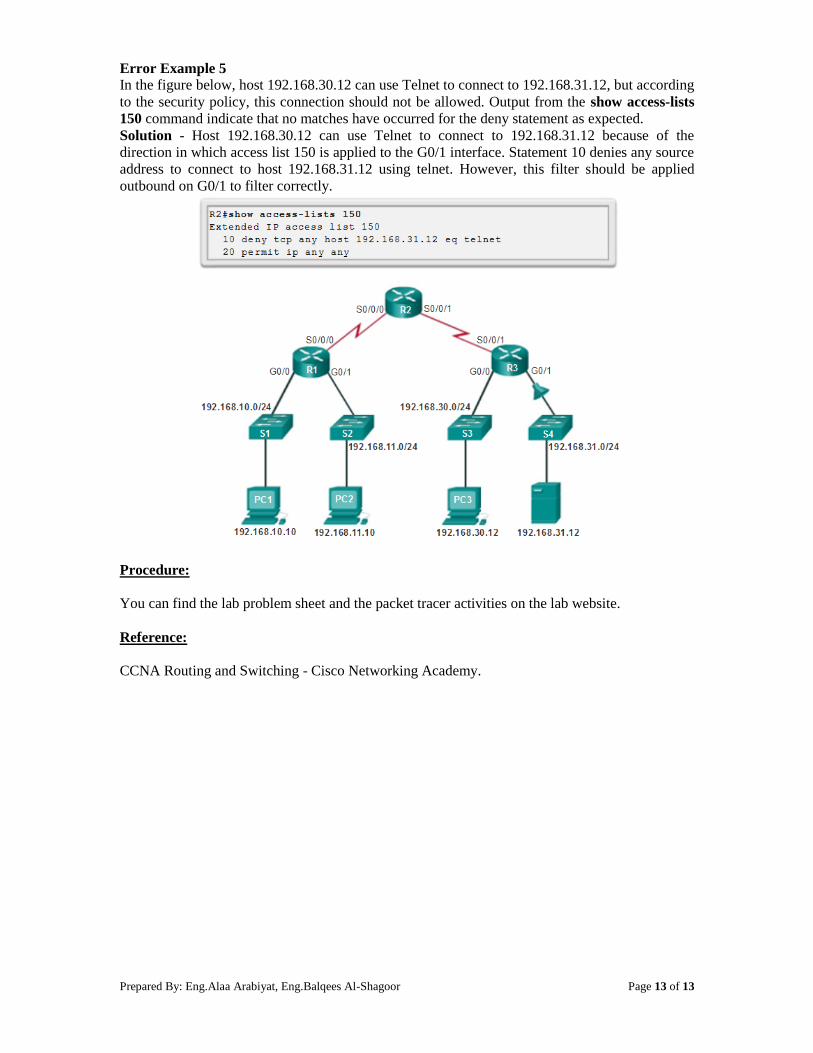
Error Example 5 In the figure below, host 192.168.30.12 can use Telnet to connect to 192.168.31.12, but according
to the security policy, this connection should not be allowed. Output from the show access-lists
150 command indicate that no matches have occurred for the deny statement as expected.
Solution - Host 192.168.30.12 can use Telnet to connect to 192.168.31.12 because of the
direction in which access list 150 is applied to the G0/1 interface. Statement 10 denies any source
address to connect to host 192.168.31.12 using telnet. However, this filter should be applied
outbound on G0/1 to filter correctly.
Procedure:
You can find the lab problem sheet and the packet tracer activities on the lab website.
Reference:
CCNA Routing and Switching - Cisco Networking Academy.
Prepared By: Eng.Alaa Arabiyat, Eng.Balqees Al-Shagoor Page 1 of 13
University of Jordan
Faculty of Engineering & Technology
Computer Engineering Department
Advance Networks Laboratory 0907529
Exp.1 Access Control Lists (ACLs)
Objectives 1. Explain how ACLs are used to filter traffic.
2. Compare standard and extended IPv4 ACLs.
3. Explain the guidelines for creating and placement of ACLs.
4. Modify ACLs.
5. Explain how a router processes packets when an ACL is applied.
6. Troubleshoot common ACL errors.
1. Purpose of ACLs:
Network security is a huge subject, and one of the most important skills a network administrator
needs is mastery of access control lists (ACLs).
Network designers use firewalls to protect networks from unauthorized use. Firewalls are
hardware or software solutions that enforce network security policies. Consider a lock on a door
to a room inside a building. The lock allows only authorized users with a key or access card to
pass through the door. Similarly, a firewall filters unauthorized or potentially dangerous packets
from entering the network. On a Cisco router, you can configure a simple firewall that provides
basic traffic filtering capabilities using ACLs. Administrators use ACLs to stop traffic or permit
only specified traffic on their networks.
An ACL is a sequential list of permit or deny statements that apply to addresses or upper-layer
protocols based on information found in the packet header. ACLs provide a powerful way to
control traffic into and out of a network. ACLs can be configured for all routed network
protocols.
When configured, ACLs perform the following tasks as shown in the figure below:
Limit network traffic to increase network performance. For example, if corporate policy
does not allow video traffic on the network, ACLs that block video traffic could be
configured and applied. This would greatly reduce the network load and increase network
performance.
Provide traffic flow control. ACLs can restrict the delivery of routing updates. If updates
are not required because of network conditions, bandwidth is preserved.
Provide a basic level of security for network access. ACLs can allow one host to access a
part of the network and prevent another host from accessing the same area. For example,
access to the Human Resources network can be restricted to authorized users.
Filter traffic based on traffic type. For example, an ACL can permit email traffic, but
block all Telnet traffic.
Screen hosts to permit or deny access to network services. ACLs can permit or deny a
user to access file types, such as FTP or HTTP.
Prepared By: Eng.Alaa Arabiyat, Eng.Balqees Al-Shagoor Page 2 of 13
By default, a router does not have ACLs configured; therefore, by default a router does not filter
traffic. Traffic that enters the router is routed solely based on information within the routing table.
However, when an ACL is applied to an interface, the router performs the additional task of
evaluating all network packets as they pass through the interface to determine if the packet can be
forwarded.
An ACL is a sequential list of permit or deny statements, known as access control entries (ACEs).
ACEs are also commonly called ACL statements. ACEs can be created to filter traffic based on
certain criteria such as: the source address, destination address, the protocol, and port numbers.
When network traffic passes through an interface configured with an ACL, the router compares
the information within the packet against each ACE, in sequential order, to determine if the
packet matches one of the statements. If a match is found, the packet is processed accordingly. In
this way, ACLs can be configured to control access to a network or subnet.
To evaluate network traffic, the ACL extracts the following information from the Layer 3 packet
header:
Source IP address
Destination IP address
ICMP message type
The ACL can also extract upper layer information from the Layer 4 header, including:
TCP/UDP source port
TCP/UDP destination port
ACLs define the set of rules that give added control for packets that enter inbound interfaces,
packets that relay through the router and packets that exit outbound interfaces of the router. ACLs
do not act on packets that originate from the router itself.
ACLs are configured to apply to inbound traffic or to apply to outbound traffic as shown in the
figure.
Inbound ACLs - Incoming packets are processed before they are routed to the outbound
interface. An inbound ACL is efficient because it saves the overhead of routing lookups
if the packet is discarded. If the packet is permitted by the tests, it is then processed for
routing. Inbound ACLs are best used to filter packets when the network attached to an
inbound interface is the only source of the packets needed to be examined.
Outbound ACLs - Incoming packets are routed to the outbound interface, and then they
are processed through the outbound ACL. Outbound ACLs are best used when the same
filter will be applied to packets coming from multiple inbound interfaces before exiting
the same outbound interface.
The last statement of an ACL is always an implicit deny. This statement is automatically inserted
at the end of each ACL even though it is not physically present. The implicit deny blocks all
Prepared By: Eng.Alaa Arabiyat, Eng.Balqees Al-Shagoor Page 3 of 13
traffic. Because of this implicit deny, an ACL that does not have at least one permit statement
will block all traffic.
2. Standard versus Extended IPv4 ACLs:
The two types of Cisco IPv4 ACLs are standard and extended. Standard ACLs can be used to
permit or deny traffic only from source IPv4 addresses. The destination of the packet and the
ports involved are not evaluated. The example below allows all traffic from the 192.168.30.0/24
network. Because of the implied "deny any" at the end, all other traffic is blocked with this ACL.
Standard ACLs are created in global configuration mode.
R1(config)# access-list 10 permit 192.168.30.0 0.0.0.255
Extended ACLs filter IPv4 packets based on several attributes:
Protocol type
Source IPv4 address
Destination IPv4 address
Source TCP or UDP ports
Destination TCP or UDP ports
In the example below, ACL 103 permits traffic originating from any address on the
192.168.30.0/24 network to any IPv4 network if the destination host port is 80 (HTTP). Extended
ACLs are created in global configuration mode.
R1(config)# access-list 103 permit tcp 192.168.30.0 0.0.0.255 any eq80
The commands for standard and extended ACLs are explained in more details later in this
experiment.
Standard and extended ACLs can be created using either a number or a name to identify the ACL
and its list of statements. Using numbered ACLs is an effective method for determining the ACL
type on smaller networks with more homogeneously defined traffic. However, a number does not
provide information about the purpose of the ACL.
Numbered ACL: Assign a number based on protocol to be filtered.
(1 to 99) and (1300 to 1999): Standard IP ACL
(100 to 199) and (2000 to 2699): Extended IP ACL
Named ACL: Assign a name to identify the ACL.
Names can contain alphanumeric characters.
It is suggested that the name be written in CAPITAL LETTERS.
Names cannot contain spaces or punctuation.
Entries can be added or deleted within the ACL.
Writing ACLs can be a complex task. For every interface there may be multiple policies needed
to manage the type of traffic allowed to enter or exit that interface. The router in the figure has
two interfaces configured for IPv4 and IPv6. If we needed ACLs for both protocols, on both
interfaces and in both directions, this would require eight separate ACLs. Each interface would
have four ACLs; two ACLs for IPv4 and two ACLs for IPv6. For each protocol, one ACL is for
inbound traffic and one for outbound traffic.
The Three Ps:
A general rule for applying ACLs on a router can be recalled by remembering the three Ps. You
can configure one ACL per protocol, per direction, per interface:
One ACL per protocol - To control traffic flow on an interface, an ACL must be defined
for each protocol enabled on the interface.
One ACL per direction - ACLs control traffic in one direction at a time on an interface.
Two separate ACLs must be created to control inbound and outbound traffic.
Prepared By: Eng.Alaa Arabiyat, Eng.Balqees Al-Shagoor Page 4 of 13
One ACL per interface - ACLs control traffic for an interface, for example,
GigabitEthernet 0/0.
The proper placement of an ACL can make the network operate more efficiently. An ACL can be
placed to reduce unnecessary traffic. For example, traffic that will be denied at a remote
destination should not be forwarded using network resources along the route to that destination.
Every ACL should be placed where it has the greatest impact on efficiency. As shown in the
figure below, the basic rules are:
Extended ACLs - Locate extended ACLs as close as possible to the source of the traffic
to be filtered. This way, undesirable traffic is denied close to the source network without
crossing the network infrastructure.
Standard ACLs - Because standard ACLs do not specify destination addresses, place
them as close to the destination as possible. Placing a standard ACL at the source of the
traffic will effectively prevent that traffic from reaching any other networks through the
interface where the ACL is applied.
Wildcard Masks in ACLs
IPv4 ACEs include the use of wildcard masks. A wildcard mask is a string of 32 binary digits
used by the router to determine which bits of the address to examine for a match.
Subnet masks use binary 1s and 0s to identify the network, subnet, and host portion of an IP
address. Wildcard masks use binary 1s and 0s to filter individual IP addresses or groups of IP
addresses to permit or deny access to resources.
Wildcard masks and subnet masks differ in the way they match binary 1s and 0s. Wildcard masks
use the following rules to match binary 1s and 0s:
Wildcard mask bit 0 - Match the corresponding bit value in the address.
Wildcard mask bit 1 - Ignore the corresponding bit value in the address.

Prepared By: Eng.Alaa Arabiyat, Eng.Balqees Al-Shagoor Page 5 of 13
The following is an example on how to deal with wildcard masks:
Decimal Address Binary Address
IP Address to be processed 192.168.10.0 11000000.10101000.00001010.00000000
Wild Mask 0.0.255.255 00000000. 00000000.11111111. 11111111
Resulting IP Address 192.168.0.0 11000000.10101000. 00000000. 00000000
The any and host keywords: any keyword to substitute for the IPv4 address 0.0.0.0 with a
wildcard mask of 255.255.255.255 as shown in the example below:
R1(config)# access-list 1 permit 0.0.0.0 255.255. 255.255
R1(config)# access-list 1 permit any
The host keyword to substitute for the wildcard mask when identifying a single host as shown in
the example below.
R1(config)# access-list 1 permit 192.168.10.10 0.0.0.0
R1(config)# access-list 1 permit host 192.168.10.10
3. ACL Creation and Placement:
Configuring Standard ACLs:
To use numbered standard ACLs on a Cisco router, you must first create the standard ACL and
then activate the ACL on an interface. The access-list global configuration command defines a
standard ACL with a number in the range of 1 through 99. The full syntax of the standard ACL
command is as follows:
Router(config)# access-list access-list-number { deny | permit } source [ source-wildcard ]
ACEs can deny or permit an individual host or a range of host addresses. If you want to remove
the ACL, the global configuration no access-list command is used. Issuing the show access-list
command confirms that access list 10 has been removed.
After a standard ACL is configured, it is linked to an interface using the ip access-group
command in interface configuration mode:
Router(config-if)# ip access-group { access-list-number | access-list-name } { in | out }
Prepared By: Eng.Alaa Arabiyat, Eng.Balqees Al-Shagoor Page 6 of 13
To remove an ACL from an interface, first enter the no ip access-group command on the
interface, and then enter the global no access-list command to remove the entire ACL.
To create a statement that will permit a range of IPv4 addresses in a numbered ACL 10 that
permits all IPv4 addresses in the network 192.168.10.0/24, you would enter:
R1(config)# access-list 10 permit 192.168.10.10 0.0.0.255
To apply a numbered standard ACL 10 on a router, you would enter:
R1(config)#interface serial 0/0/0
R1(config-if)# ip access-group 10 out
This ACL allows only traffic from source network 192.168.10.0 to be forwarded out of interface
S0/0/0. Traffic from networks other than 192.168.10.0 is blocked.
Naming an ACL makes it easier to understand its function. For example, the above ACL could be
called VLAN10_ALLOW. When you identify your ACL with a name instead of with a number,
the configuration mode and command syntax are slightly different as shown below.
R1(config)# ip access-list standard VLAN10_ALLOW
R1(config-std-nacl)# permit 192.168.10.10 0.0.0.255
R1(config-std-nacl)#exit
R1(config)#interface serial 0/0/0
R1(config-if)# ip access-group VLAN10_ALLOW out
Using an ACL to Control VTY Access:
Restricting VTY access is a technique that allows you to define which IP addresses are allowed
Telnet access to the router EXEC process. You can control which administrative workstation or
network manages your router with an ACL and an access-class statement configured on your
VTY lines.
An example allowing a range of addresses to access VTY lines 0 - 4 is shown below.
Configure the vty lines to accept incoming telnet connections using access list 21.
R1(config)# line vty 0 4
R1(config-line)# access-class 21 in
Create access list 21 to permit the 192.168.10.0/24 network to access VTY lines 0 - 4 and
explicitly deny all others.
R1(config)# access-list 21 permit 192.168.10.0 0.0.0.255
R1(config)# access-list 21 deny any

Prepared By: Eng.Alaa Arabiyat, Eng.Balqees Al-Shagoor Page 7 of 13
Configuring Extended ACLs:
The procedural steps for configuring extended ACLs are the same as for standard ACLs. The
extended ACL is first configured, and then it is activated on an interface. However, the command
syntax and parameters are more complex to support the additional features provided by extended
ACLs. The common command syntax for extended IPv4 ACLs is shown below. Note that there
are many keywords and parameters for extended ACLs. It is not necessary to use all of the
keywords and parameters when configuring an extended ACL.
Router(config)# access-list access-list-number { deny | permit } protocol source [ source-
wildcard ] [port port-number or name] destination [destination-wildcard] [port port-number or
name] [established]
The following is an example of an extended ACL. In this example, the network administrator has
configured ACLs to restrict network access to allow website browsing only from the LAN
attached to interface G0/0 to any external network. ACL 103 allows traffic coming from any
address on the 192.168.10.0 network to go to any destination, subject to the limitation that the
traffic is using ports 80 (HTTP) and 443 (HTTPS) only so that 192.168.10.0/24 network to
browse both insecure and secure websites..
The nature of HTTP requires that traffic flow back into the network from websites accessed from
internal clients. The network administrator wants to restrict that return traffic to HTTP exchanges
from requested websites, while denying all other traffic. ACL 104 does that by blocking all
incoming traffic, except for previously established connections. The permit statement in ACL 104
allows inbound traffic using the established parameter. Without the established parameter in the
ACL statement, clients could send traffic to a web server, but not receive traffic returning from
the web server.
ACL 103 allows requests to ports 80 and 443.
ACL 104 allows established HTTP and HTTPS replies.
The example shown in the figure below denies FTP traffic from subnet 192.168.11.0 that is going
to subnet 192.168.10.0, but permits all other traffic. Note the use of wildcard masks and the
explicit deny any statement. Remember that FTP uses TCP ports 20 and 21; therefore the ACL
requires both port name keywords ftp and ftp-data or eq 20 and eq 21 to deny FTP.
If using port numbers instead of port names, the commands would be written as:
Prepared By: Eng.Alaa Arabiyat, Eng.Balqees Al-Shagoor Page 8 of 13
access-list 114 permit tcp 192.168.20.0 0.0.0.255 any eq 20
access-list 114 permit tcp 192.168.20.0 0.0.0.255 any eq 21 To prevent the implied deny any statement at the end of the ACL from blocking all traffic, the
permit ip any any statement is added. Without at least one permit statement in an ACL, all
traffic on the interface where that ACL was applied would be dropped. The ACL should be
applied inbound on the G0/1 interface so that traffic from the 192.168.11.0/24 LAN is filtered as
it enters the router interface.
Named extended ACLs are created in essentially the same way that named standard ACLs are
created. The figure below shows the named versions of the ACLs created in a previous example.
4. Modify ACLs.
Editing an extended ACL can be accomplished using the same process as editing a standard ACL.
An ACL can be modified using:

Prepared By: Eng.Alaa Arabiyat, Eng.Balqees Al-Shagoor Page 9 of 13
Method 1 Text editor - Using this method, the ACL is copied and pasted into the text
editor where the changes are made. The current access list is removed using the no
access-list command. The modified ACL is then pasted back into the configuration.
Method 2 Sequence numbers - Sequence numbers can be used to delete or insert an
ACL statement. The ip access-list {standard | extended} name command is used to
enter named-ACL configuration mode. If the ACL is numbered instead of named, the
ACL number is used in the name parameter. ACEs can be inserted or removed.
In the figure below the administrator needs to edit the ACL named SURFING to correct a typo in
the source network statement. To view the current sequence numbers, the show access-lists
command is used. The statement to be edited is identified as statement 10. The original statement
is removed with the no sequence_# command. The corrected statement is added replacing the
original statement.
5. Processing Packets with ACLs
Inbound ACL Logic If the information in a packet header and the first ACL statement match, the rest of the statements
in the list are skipped, and the packet is permitted or denied as specified by the matched
statement. If a packet header does not match an ACL statement, the packet is tested against the
next statement in the list. This matching process continues until the end of the list is reached.
At the end of every ACL is a statement is an implicit deny any statement. This statement is not
shown in output. This final implied statement applied to all packets for which conditions did not
test true. This final test condition matches all other packets and results in a "deny" action. Instead
of proceeding into or out of an interface, the router drops all of these remaining packets. This
final statement is often referred to as the "implicit deny any statement" or the "deny all traffic"
statement. Because of this statement, an ACL should have at least one permit statement in it;
otherwise, the ACL blocks all traffic.
Outbound ACL Logic Before a packet is forwarded to an outbound interface, the router checks the routing table to see if
the packet is routable. If the packet is not routable, it is dropped and is not tested against the
ACEs. Next, the router checks to see whether the outbound interface is grouped to an ACL. If the
Prepared By: Eng.Alaa Arabiyat, Eng.Balqees Al-Shagoor Page 10 of 13
outbound interface is not grouped to an ACL, the packet can be sent to the output buffer.
Examples of outbound ACL operation are as follows:
No ACL applied to the interface: If the outbound interface is not grouped to an
outbound ACL, the packet is sent directly to the outbound interface.
ACL applied to the interface: If the outbound interface is grouped to an outbound ACL,
the packet is not sent out on the outbound interface until it is tested by the combination of
ACEs that are associated with that interface. Based on the ACL tests, the packet is
permitted or denied.
For outbound lists, "permit" means to send the packet to the output buffer, and "deny" means to
discard the packet.
6. Troubleshoot ACLs
Using the show commands reveals most of the more common ACL errors. The most common
errors are entering ACEs in the wrong order and not applying adequate criteria to the ACL rules.
Error Example 1 In the figure below, host 192.168.10.10 has no connectivity with 192.168.30.12. When viewing
the output of the show access-lists command, matches are shown for the first deny statement.
This is an indicator that this statement has been matched by traffic.
Solution - Look at the order of the ACEs (ACL Entries). Host 192.168.10.10 has no connectivity
with 192.168.30.12 because of the order of rule 10 in the access list. Because the router processes
ACLs from the top down, statement 10 denies host 192.168.10.10, so statement 20 can never be
matched. Statements 10 and 20 should be reversed. The last line allows all other non-TCP traffic
that falls under IP (ICMP, UDP, etc.).
Prepared By: Eng.Alaa Arabiyat, Eng.Balqees Al-Shagoor Page 11 of 13
Error Example 2 In the figure above, the 192.168.10.0/24 network cannot use TFTP to connect to the
192.168.30.0/24 network.
Solution - The 192.168.10.0/24 network cannot use TFTP to connect to the 192.168.30.0/24
network because TFTP uses the transport protocol UDP. Statement 30 in access list 120 allows all
other TCP traffic. However, because TFTP uses UDP instead of TCP, it is implicitly denied.
Recall that the implied deny any statement does not appear in show access-lists output and
therefore matches are not shown. Statement 30 should be ip any any.
This ACL works whether it is applied to G0/0 of R1, or S0/0/1 of R3, or S0/0/0 of R2 in the
incoming direction. However, based on the rule about placing extended ACLs closest to the
source, the best option is to place it inbound on G0/0 of R1 because it allows undesirable traffic
to be filtered without crossing the network infrastructure.

Prepared By: Eng.Alaa Arabiyat, Eng.Balqees Al-Shagoor Page 12 of 13
Error Example 3 In the figure above, the 192.168.11.0/24 network can use Telnet to connect to 192.168.30.0/24,
but according to company policy, this connection should not be allowed. The results of the show
access-lists 130 command indicate that the permit statement has been matched.
Solution - The 192.168.11.0/24 network can use Telnet to connect to the 192.168.30.0/24
network, because the Telnet port number in statement 10 of access list 130 is listed in the wrong
position in the ACL statement. Statement 10 currently denies any source packet with a port
number that is equal to Telnet. To deny Telnet traffic inbound on G0/1, deny the destination port
number that is equal to Telnet, for example, deny tcp any any eq telnet.
Error Example 4 In the figure below, host 192.168.30.12 is able to Telnet to connect to 192.168.31.12, but
company policy states that this connection should not be allowed. Output from the show access-
lists 140 command indicate that the permit statement has been matched.
Solution - Host 192.168.30.12 can use Telnet to connect to 192.168.31.12 because there are no
rules that deny host 192.168.30.12 or its network as the source. Statement 10 of access list 140
denies the router interface on which traffic enters the router. The host IPv4 address in statement
10 should be 192.168.30.12.

Prepared By: Eng.Alaa Arabiyat, Eng.Balqees Al-Shagoor Page 13 of 13
Error Example 5 In the figure below, host 192.168.30.12 can use Telnet to connect to 192.168.31.12, but according
to the security policy, this connection should not be allowed. Output from the show access-lists
150 command indicate that no matches have occurred for the deny statement as expected.
Solution - Host 192.168.30.12 can use Telnet to connect to 192.168.31.12 because of the
direction in which access list 150 is applied to the G0/1 interface. Statement 10 denies any source
address to connect to host 192.168.31.12 using telnet. However, this filter should be applied
outbound on G0/1 to filter correctly.
Procedure:
You can find the lab problem sheet and the packet tracer activities on the lab website.
Reference:
CCNA Routing and Switching - Cisco Networking Academy.
Prepared By: Dr.Ali Elmosa, Eng.Alaa Arabiyat Page 1 of 12
University of Jordan
Faculty of Engineering & Technology
Computer Engineering Department
Advance Networks Laboratory 0907529
Exp.2 Network Address Translation for IPv4 (NAT)
Objectives 1. Describe NAT operation.
2. Describe the benefits and drawbacks of NAT.
3. Configure static NAT using the CLI.
4. Configure dynamic NAT using the CLI.
5. Configure PAT using the CLI.
6. Use show commands to verify NAT operation.
1. NAT Operation:
All public IPv4 addresses that transverse the Internet must be registered with a Regional Internet
Registry (RIR). Organizations can lease public addresses from a service provider (SP), but only
the registered holder of a public Internet address can assign that address to a network device.
However, with a theoretical maximum of 4.3 billion addresses (232
), IPv4 address space is
severely limited. When Bob Kahn and Vint Cerf first developed the suite of TCP/IP protocols
including IPv4 in 1981, they never envisioned what the Internet would become. At the time, the
personal computer was mostly a curiosity for hobbyists and the World Wide Web was still more
than a decade away.
With the proliferation of personal computing and the advent of the World Wide Web, it soon
became obvious that 4.3 billion IPv4 addresses would not be enough. The long term solution was
IPv6, but more immediate solutions to address exhaustion were required. For the short term,
several solutions were implemented by the IETF including Network Address Translation (NAT)
and RFC 1918 private IPv4 addresses. This experiment discusses how NAT, combined with the
use of private address space, is used to both conserve and more efficiently use IPv4 addresses to
provide networks of all sizes access to the Internet.
Networks are commonly implemented using private IPv4 addresses, as defined in RFC 1918. The
figure below shows the range of addresses included in RFC 1918.
These private addresses are used within an organization or site to allow devices to communicate
locally. However, because these addresses do not identify any single company or organization,
private IPv4 addresses cannot be routed over the Internet. To allow a device with a private IPv4
address to access devices and resources outside of the local network, the private address must first
be translated to a public address.
NAT provides the translation of private addresses to public addresses. This allows a device with a
private IPv4 address to access resources outside of their private network, such as those found on
the Internet. NAT combined with private IPv4 addresses, has proven to be a useful method of
preserving public IPv4 addresses. A single, public IPv4 address can be shared by hundreds, even
thousands of devices, each configured with a unique private IPv4 address.
Prepared By: Dr.Ali Elmosa, Eng.Alaa Arabiyat Page 2 of 12
Without NAT, the exhaustion of the IPv4 address space would have occurred well before the year
2000. However, NAT has certain limitations, which will be explored later. The solution to the
exhaustion of IPv4 address space and the limitations of NAT is the eventual transition to IPv6.
NAT has many uses, but its primary use is to conserve public IPv4 addresses. NAT has an added
benefit of adding a degree of privacy and security to a network, because it hides internal IPv4
addresses from outside networks.
NAT-enabled routers can be configured with one or more valid public IPv4 addresses. These
public addresses are known as the NAT pool. When an internal device sends traffic out of the
network, the NAT-enabled router translates the internal IPv4 address of the device to a public
address from the NAT pool. To outside devices, all traffic entering and exiting the network
appears to have a public IPv4 address from the provided pool of addresses.
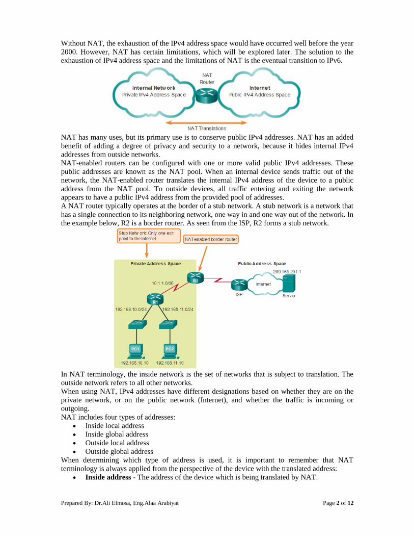
A NAT router typically operates at the border of a stub network. A stub network is a network that
has a single connection to its neighboring network, one way in and one way out of the network. In
the example below, R2 is a border router. As seen from the ISP, R2 forms a stub network.
In NAT terminology, the inside network is the set of networks that is subject to translation. The
outside network refers to all other networks.
When using NAT, IPv4 addresses have different designations based on whether they are on the
private network, or on the public network (Internet), and whether the traffic is incoming or
outgoing.
NAT includes four types of addresses:
Inside local address
Inside global address
Outside local address
Outside global address
When determining which type of address is used, it is important to remember that NAT
terminology is always applied from the perspective of the device with the translated address:
Inside address - The address of the device which is being translated by NAT.
Prepared By: Dr.Ali Elmosa, Eng.Alaa Arabiyat Page 3 of 12
Outside address - The address of the destination device.
NAT also uses the concept of local or global with respect to addresses:
Local address - A local address is any address that appears on the inside portion of the
network.
Global address - A global address is any address that appears on the outside portion of
the network.
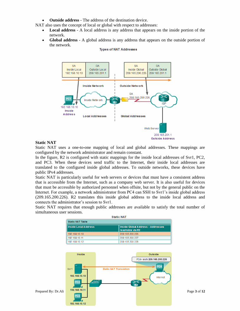
Static NAT Static NAT uses a one-to-one mapping of local and global addresses. These mappings are
configured by the network administrator and remain constant.
In the figure, R2 is configured with static mappings for the inside local addresses of Svr1, PC2,
and PC3. When these devices send traffic to the Internet, their inside local addresses are
translated to the configured inside global addresses. To outside networks, these devices have
public IPv4 addresses.
Static NAT is particularly useful for web servers or devices that must have a consistent address
that is accessible from the Internet, such as a company web server. It is also useful for devices
that must be accessible by authorized personnel when offsite, but not by the general public on the
Internet. For example, a network administrator from PC4 can SSH to Svr1’s inside global address
(209.165.200.226). R2 translates this inside global address to the inside local address and
connects the administrator’s session to Svr1.
Static NAT requires that enough public addresses are available to satisfy the total number of
simultaneous user sessions.
Prepared By: Dr.Ali Elmosa, Eng.Alaa Arabiyat Page 4 of 12
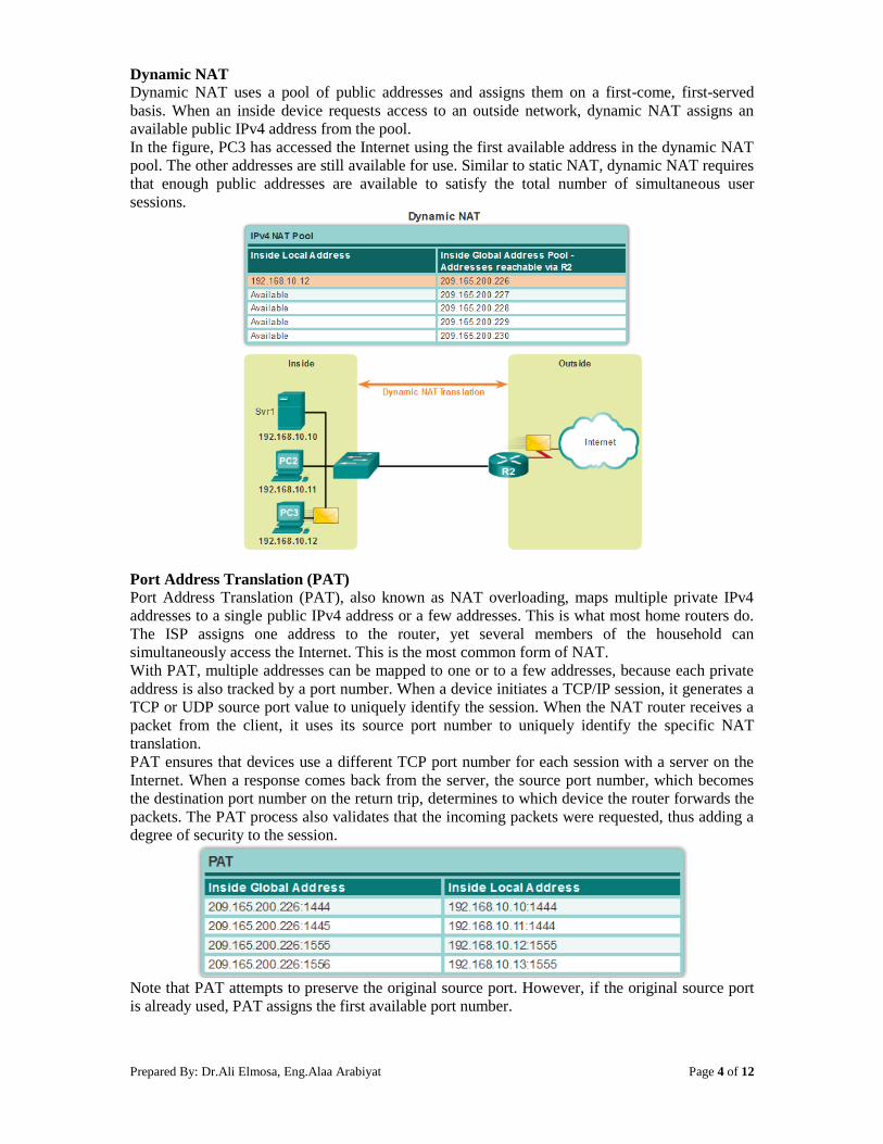
Dynamic NAT
Dynamic NAT uses a pool of public addresses and assigns them on a first-come, first-served
basis. When an inside device requests access to an outside network, dynamic NAT assigns an
available public IPv4 address from the pool.
In the figure, PC3 has accessed the Internet using the first available address in the dynamic NAT
pool. The other addresses are still available for use. Similar to static NAT, dynamic NAT requires
that enough public addresses are available to satisfy the total number of simultaneous user
sessions.
Port Address Translation (PAT)
Port Address Translation (PAT), also known as NAT overloading, maps multiple private IPv4
addresses to a single public IPv4 address or a few addresses. This is what most home routers do.
The ISP assigns one address to the router, yet several members of the household can
simultaneously access the Internet. This is the most common form of NAT.
With PAT, multiple addresses can be mapped to one or to a few addresses, because each private
address is also tracked by a port number. When a device initiates a TCP/IP session, it generates a
TCP or UDP source port value to uniquely identify the session. When the NAT router receives a
packet from the client, it uses its source port number to uniquely identify the specific NAT
translation.
PAT ensures that devices use a different TCP port number for each session with a server on the
Internet. When a response comes back from the server, the source port number, which becomes
the destination port number on the return trip, determines to which device the router forwards the
packets. The PAT process also validates that the incoming packets were requested, thus adding a
degree of security to the session.
Note that PAT attempts to preserve the original source port. However, if the original source port
is already used, PAT assigns the first available port number.
Prepared By: Dr.Ali Elmosa, Eng.Alaa Arabiyat Page 5 of 12
2. Benefits of NAT
NAT provides many benefits, including:
NAT conserves the legally registered addressing scheme by allowing the privatization of
intranets. NAT conserves addresses through application port-level multiplexing. With
NAT overload, internal hosts can share a single public IPv4 address for all external
communications. In this type of configuration, very few external addresses are required to
support many internal hosts.
NAT increases the flexibility of connections to the public network. Multiple pools,
backup pools, and load-balancing pools can be implemented to ensure reliable public
network connections.
NAT provides consistency for internal network addressing schemes. On a network not
using private IPv4 addresses and NAT, changing the public IPv4 address scheme requires
the readdressing of all hosts on the existing network. The costs of readdressing hosts can
be significant. NAT allows the existing private IPv4 address scheme to remain while
allowing for easy change to a new public addressing scheme. This means an organization
could change ISPs and not need to change any of its inside clients.
NAT provides network security. Because private networks do not advertise their
addresses or internal topology, they remain reasonably secure when used in conjunction
with NAT to gain controlled external access. However, NAT does not replace firewalls.
NAT does have some drawbacks. The fact that hosts on the Internet appear to communicate
directly with the NAT-enabled device, rather than with the actual host inside the private
network, creates a number of issues.
One disadvantage of using NAT is related to network performance, particularly for real time
protocols such as VoIP. NAT increases switching delays because the translation of each IPv4
address within the packet headers takes time. The first packet is process-switched; it always
goes through the slower path. The router must look at every packet to decide whether it needs
translation. The router must alter the IPv4 header, and possibly alter the TCP or UDP header.
The IPv4 header checksum, along with the TCP or UDP checksum must be recalculated each
time a translation is made. Remaining packets go through the fast-switched path if a cache
entry exists; otherwise, they too are delayed.
Another disadvantage of using NAT is that end-to-end addressing is lost. Many Internet
protocols and applications depend on end-to-end addressing from the source to the
destination. Some applications do not work with NAT. For example, some security
applications, such as digital signatures, fail because the source IPv4 address changes before
reaching the destination. Applications that use physical addresses, instead of a qualified
domain name, do not reach destinations that are translated across the NAT router. Sometimes,
this problem can be avoided by implementing static NAT mappings.
End-to-end IPv4 traceability is also lost. It becomes much more difficult to trace packets that
undergo numerous packet address changes over multiple NAT hops, making troubleshooting
challenging.
3. Configuring Static NAT
Static NAT is a one-to-one mapping between an inside address and an outside address. There are
two basic tasks when configuring static NAT translations.
Step 1. The first task is to create a mapping between the inside local address and the inside global
addresses. For example, the 192.168.10.254 inside local address and the 209.165.201.5 inside
global address in the figure below are configured as a static NAT translation.
Router(config)# ip nat inside source static local-ip global-ip
Step 2. After the mapping is configured, the interfaces participating in the translation are
configured as inside or outside relative to NAT. In the example, the Serial 0/0/0 interface of R2 is
an inside interface and Serial 0/1/0 is an outside interface.
Router(config)# interface type number
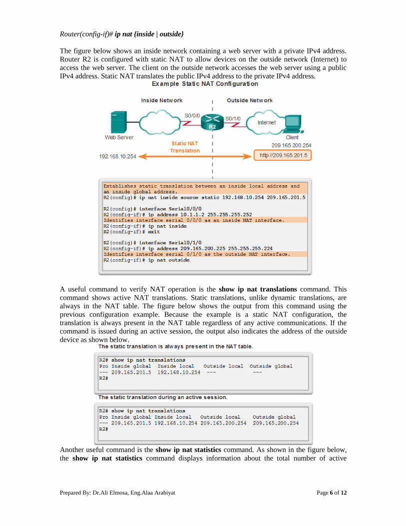
Prepared By: Dr.Ali Elmosa, Eng.Alaa Arabiyat Page 6 of 12
Router(config-if)# ip nat {inside | outside}
The figure below shows an inside network containing a web server with a private IPv4 address.
Router R2 is configured with static NAT to allow devices on the outside network (Internet) to
access the web server. The client on the outside network accesses the web server using a public
IPv4 address. Static NAT translates the public IPv4 address to the private IPv4 address.
A useful command to verify NAT operation is the show ip nat translations command. This
command shows active NAT translations. Static translations, unlike dynamic translations, are
always in the NAT table. The figure below shows the output from this command using the
previous configuration example. Because the example is a static NAT configuration, the
translation is always present in the NAT table regardless of any active communications. If the
command is issued during an active session, the output also indicates the address of the outside
device as shown below.
Another useful command is the show ip nat statistics command. As shown in the figure below,
the show ip nat statistics command displays information about the total number of active

Prepared By: Dr.Ali Elmosa, Eng.Alaa Arabiyat Page 7 of 12
translations, NAT configuration parameters, the number of addresses in the pool, and the number
of addresses that have been allocated.
To verify that the NAT translation is working, it is best to clear statistics from any past
translations using the clear ip nat statistics command before testing.
Prior to any communications with the web server, the show ip nat statistics command shows no
current hits. After the client establishes a session with the web server, the show ip nat statistics
command has been incremented to five hits. This verifies that the static NAT translation is taking
place on R2.
4. Configuring Dynamic NAT
While static NAT provides a permanent mapping between an inside local address and an inside
global address, dynamic NAT allows the automatic mapping of inside local addresses to inside
global addresses. These inside global addresses are typically public IPv4 addresses. Dynamic
NAT uses a group, or pool of public IPv4 addresses for translation.
Dynamic NAT, like static NAT, requires the configuration of the inside and outside interfaces
participating in NAT.
The example topology shown below has an inside network using addresses from the RFC 1918
private address space. Attached to router R1 are two LANs, 192.168.10.0/24 and
192.168.11.0/24. Router R2, the border router, is configured for dynamic NAT using a pool of
public IPv4 addresses 209.165.200.226 through 209.165.200.240.
The pool of public IPv4 addresses (inside global address pool) is available to any device on the
inside network on a first-come first-served basis. With dynamic NAT, a single inside address is
translated to a single outside address. With this type of translation there must be enough addresses
in the pool to accommodate all the inside devices needing access to the outside network at the
same time. If all of the addresses in the pool have been used, a device must wait for an available
address before it can access the outside network.

Prepared By: Dr.Ali Elmosa, Eng.Alaa Arabiyat Page 8 of 12
The steps and the commands used to configure dynamic NAT are as follows:
Step 1. Define the pool of addresses that will be used for translation using the ip nat pool
command. This pool of addresses is typically a group of public addresses. The addresses are
defined by indicating the starting IP address and the ending IP address of the pool. The netmask
or prefix-length keyword indicates which address bits belong to the network and which bits
belong to the host for the range of addresses.
Step 2. Configure a standard ACL to identify (permit) only those addresses that are to be
translated. An ACL that is too permissive can lead to unpredictable results. Remember there is an
implicit deny all statement at the end of each ACL.
Step 3. Bind the ACL to the pool. The ip nat inside source list access-list-number number pool
pool name command is used to bind the ACL to the pool. This configuration is used by the router
to identify which devices (list) receive which addresses (pool).
Step 4. Identify which interfaces are inside, in relation to NAT; that is, any interface that
connects to the inside network.
Step 5. Identify which interfaces are outside, in relation to NAT; that is, any interface that
connects to the outside network.
Prepared By: Dr.Ali Elmosa, Eng.Alaa Arabiyat Page 9 of 12
Define a pool of public IPv4 addresses 209.165.200.241 to 209.165.200.250 with pool name
PUBLIC-POOL.
R2(config)# ip nat pool PUBLIC-POOL 209.165.200.241 209.165.200.250 netmask
255.255.255.224
Configure ACL 2 to permit devices from 192.168.10.0/24 network to be translated by NAT.
R2(config)# access-list 2 permit 192.168.10.0 0.0.0.255
Bind PUBLIC-POOL with ACL 2.
R2(config)# ip nat inside source list 2 pool PUBLIC-POOL
Configure the proper inside NAT interface.
R2(config)# interface Serial0/0/0
R2(config-if)# ip nat inside
Configure the proper outside NAT interface.
R2(config)# interface Serial0/1/0
R2(config-if)# ip nat outside
You successfully configured dynamic NAT.
The output of the show ip nat translations command shown below displays the details of the
two previous NAT assignments. The command displays all static translations that have been
configured and any dynamic translations that have been created by traffic.
By default, translation entries time out after 24 hours, unless the timers have been reconfigured
with the ip nat translation timeout timeout-seconds command in global configuration mode.
To clear dynamic entries before the timeout has expired, use the clear ip nat translation global
configuration mode command. It is useful to clear the dynamic entries when testing the NAT
configuration.
Note:Only the dynamic translations are cleared from the table. Static translations cannot be
cleared from the translation table.
the show ip nat statistics command displays information about the total number of active
translations, NAT configuration parameters, the number of addresses in the pool, and how many
of the addresses have been allocated.
Alternatively, use the show running-config command and look for NAT, ACL, interface, or pool
commands with the required values. Examine these carefully and correct any errors discovered.

Prepared By: Dr.Ali Elmosa, Eng.Alaa Arabiyat Page 10 of 12
5. Configuring Port Address Translation (PAT)
PAT (also called NAT overload) conserves addresses in the inside global address pool by
allowing the router to use one inside global address for many inside local addresses. In other
words, a single public IPv4 address can be used for hundreds, even thousands of internal private
IPv4 addresses. When this type of translation is configured, the router maintains enough
information from higher-level protocols, TCP or UDP port numbers, for example, to translate the
inside global address back into the correct inside local address. When multiple inside local
addresses map to one inside global address, the TCP or UDP port numbers of each inside host
distinguish between the local addresses.
Note: The total number of internal addresses that can be translated to one external address could
theoretically be as high as 65,536 per IP address. However, the number of internal addresses that
can be assigned a single IP address is around 4,000.
There are two ways to configure PAT, depending on how the ISP allocates public IPv4 addresses.
In the first instance, the ISP allocates more than one public IPv4 address to the organization, and
in the other, it allocates a single public IPv4 address that is required for the organization to
connect to the ISP.
Configuring PAT for a Pool of Public IP Addresses If a site has been issued more than one public IPv4 address, these addresses can be part of a pool
that is used by PAT. This is similar to dynamic NAT, except that there are not enough public
addresses for a one-to-one mapping of inside to outside addresses. The small pool of addresses is
shared among a larger number of devices. The primary difference between this configuration and
the configuration for dynamic, one-to-one NAT is that the overload keyword is used. The
overload keyword enables PAT.
The example configuration shown below establishes overload translation for the NAT pool
named NAT-POOL2. NAT-POOL2 contains addresses 209.165.200.226 to 209.165.200.240.
Hosts in the 192.168.0.0/16 network are subject to translation. The S0/0/0 interface is identified
as an inside interface and the S0/1/0 interface is identified as an outside interface.
Prepared By: Dr.Ali Elmosa, Eng.Alaa Arabiyat Page 11 of 12
R2(config)# ip nat pool NAT-POOL2 209.165.200.226 209.165.200.240 netmask
255.255.255.224
R2(config)# access-list 1permit 192.168.0.0 0.0.255.255
R2(config)# ip nat inside source list 2 pool NAT-POOL2 overload
R2(config)# interface Serial0/0/0
R2(config-if)# ip nat inside
R2(config)# interface Serial0/1/0
R2(config-if)# ip nat outside
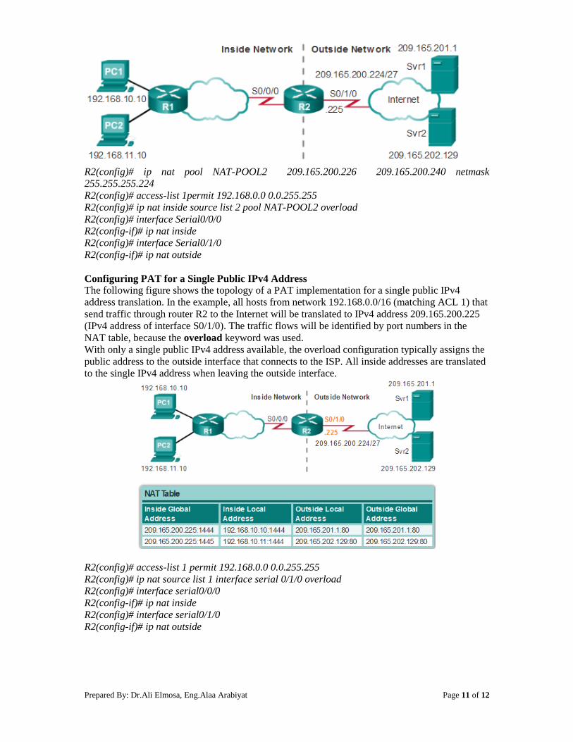
Configuring PAT for a Single Public IPv4 Address The following figure shows the topology of a PAT implementation for a single public IPv4
address translation. In the example, all hosts from network 192.168.0.0/16 (matching ACL 1) that
send traffic through router R2 to the Internet will be translated to IPv4 address 209.165.200.225
(IPv4 address of interface S0/1/0). The traffic flows will be identified by port numbers in the
NAT table, because the overload keyword was used.
With only a single public IPv4 address available, the overload configuration typically assigns the
public address to the outside interface that connects to the ISP. All inside addresses are translated
to the single IPv4 address when leaving the outside interface.
R2(config)# access-list 1 permit 192.168.0.0 0.0.255.255
R2(config)# ip nat source list 1 interface serial 0/1/0 overload
R2(config)# interface serial0/0/0
R2(config-if)# ip nat inside
R2(config)# interface serial0/1/0
R2(config-if)# ip nat outside
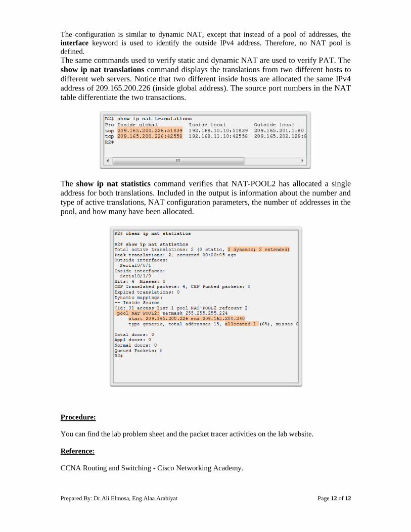
Prepared By: Dr.Ali Elmosa, Eng.Alaa Arabiyat Page 12 of 12
The configuration is similar to dynamic NAT, except that instead of a pool of addresses, the
interface keyword is used to identify the outside IPv4 address. Therefore, no NAT pool is
defined.
The same commands used to verify static and dynamic NAT are used to verify PAT. The
show ip nat translations command displays the translations from two different hosts to
different web servers. Notice that two different inside hosts are allocated the same IPv4
address of 209.165.200.226 (inside global address). The source port numbers in the NAT
table differentiate the two transactions.
The show ip nat statistics command verifies that NAT-POOL2 has allocated a single
address for both translations. Included in the output is information about the number and
type of active translations, NAT configuration parameters, the number of addresses in the
pool, and how many have been allocated.
Procedure:
You can find the lab problem sheet and the packet tracer activities on the lab website.
Reference:
CCNA Routing and Switching - Cisco Networking Academy.

Prepared By: Eng.Alaa Arabiyat, Eng.Rawan Aljamal
Revised By: Dr. Ramzi Saifan Page 1 of 13
University of Jordan
Faculty of Engineering & Technology
Computer Engineering Department
Advance Networks Laboratory 0907529
Exp.3 Virtual Local Area Networks (VLANs).
Objectives
1. Explain the role of VLANs in a network.
2. Explain the role of trunking VLANs in a network.
3. Configure VLANs on the switches in a network topology.
4. Troubleshoot the common software or hardware configuration problems associated with
VLANs.
1. Introducing VLANs:
To appreciate why VLANs are being widely used today, consider a small community college
with student dorms and the faculty offices all in one building (Building 1). The figure below
shows the student computers in one LAN and the faculty computers in another LAN. This works
fine because each department is physically together, so it is easy to provide them with their
network resources.
A year later, the college has grown and now has three buildings. In the figure, the original
network is the same, but student and faculty computers are spread out across three buildings. The
student dorms remain on the fifth floor and the faculty offices remain on the third floor. However,
now the IT department wants to ensure that student computers all share the same security features
and bandwidth controls. How can the network accommodate the shared needs of the
geographically separated departments? Do you create a large LAN and wire each department
together? How easy would it be to make changes to that network? It would be great to group the
people with the resources they use regardless of their geographic location, and it would make it
easier to manage their specific security and bandwidth needs.
The solution for the community college is to use a networking technology called a virtual LAN
(VLAN). A VLAN allows a network administrator to create groups of logically networked
devices that act as if they are on their own independent network, even if they share a common
infrastructure with other VLANs. When you configure a VLAN, you can name it to describe the
primary role of the users for that VLAN. As another example, all of the student computers in a
school can be configured in the "Student" VLAN. Using VLANs, you can logically segment
switched networks based on functions, departments, or project teams. You can also use a VLAN
to geographically structure your network to support the growing reliance of companies on home-

Prepared By: Eng.Alaa Arabiyat, Eng.Rawan Aljamal
Revised By: Dr. Ramzi Saifan Page 2 of 13
based workers. In the figure below, one VLAN is created for students and another for faculty.
These VLANs allow the network administrator to implement access and security policies to
particular groups of users. For example, the faculty staff, but not the students, can be allowed
access to e-learning management servers for developing online course materials.
A VLAN is a logically separate IP subnetwork. VLANs allow multiple IP networks and subnets
to exist on the same switched network. The figure below shows a network with three computers.
For computers to communicate on the same VLAN, each must have an IP address and a subnet
mask that is consistent for that VLAN. The switch has to be configured with the VLAN and each
port in the VLAN must be assigned to the VLAN. A switch port with a singular VLAN
configured on it is called an access port. Remember, just because two computers are physically
connected to the same switch does not mean that they can communicate. Devices on two separate
networks and subnets must communicate via a router (Layer 3), whether or not VLANs are used.
You do not need VLANs to have multiple networks and subnets on a switched network, but there
are definite advantages to using VLANs.
Benefits of a VLAN
User productivity and network adaptability are key drivers for business growth and success.
Implementing VLAN technology enables a network to more flexibly support business goals. The
primary benefits of using VLANs are as follows:
Security - Groups that have sensitive data are separated from the rest of the network,
decreasing the chances of confidential information breaches. Faculty computers are on
VLAN 10 and completely separated from student and guest data traffic.

Prepared By: Eng.Alaa Arabiyat, Eng.Rawan Aljamal
Revised By: Dr. Ramzi Saifan Page 3 of 13
Cost reduction - Cost savings result from less need for expensive network upgrades and
more efficient use of existing bandwidth and uplinks.
Higher performance - Dividing flat Layer 2 networks into multiple logical workgroups
(broadcast domains) reduces unnecessary traffic on the network and boosts performance.
Broadcast storm mitigation - Dividing a network into VLANs reduces the number of
devices that may participate in a broadcast storm since LAN segmentation prevents a
broadcast storm from propagating to the whole network. In the figure you can see that
although there are six computers on this network, there are only three broadcast domains:
Faculty, Student, and Guest.
Improved IT staff efficiency - VLANs make it easier to manage the network because
users with similar network requirements share the same VLAN. When you provision a
new switch, all the policies and procedures already configured for the particular VLAN
are implemented when the ports are assigned. It is also easy for the IT staff to identify the
function of a VLAN by giving it an appropriate name. In the figure, for easy
identification VLAN 20 has been named "Student", VLAN 10 could be named "Faculty",
and VLAN 30 "Guest."
Simpler project or application management - VLANs aggregate users and network
devices to support business or geographic requirements. Having separate functions makes
managing a project or working with a specialized application easier, for example, an e-
learning development platform for faculty. It is also easier to determine the scope of the
effects of upgrading network services.
VLAN ID Ranges
Access VLANs are divided into either a normal range or an extended range.
1. Normal Range VLANs
Used in small- and medium-sized business and enterprise networks.
Identified by a VLAN ID between 1 and 1005.
IDs 1002 through 1005 are reserved for Token Ring and FDDI VLANs.
IDs 1 and 1002 to 1005 are automatically created and cannot be removed.

Prepared By: Eng.Alaa Arabiyat, Eng.Rawan Aljamal
Revised By: Dr. Ramzi Saifan Page 4 of 13
Configurations are stored within a VLAN database file, called vlan.dat. The vlan.dat
file is located in the flash memory of the switch.
The VLAN trunking protocol (VTP), which helps manage VLAN configurations
between switches, can only learn normal range VLANs and stores them in the VLAN
database file.
2. Extended Range VLANs
Enable service providers to extend their infrastructure to a greater number of
customers. Some global enterprises could be large enough to need extended range
VLAN IDs.
Are identified by a VLAN ID between 1006 and 4094.
Support fewer VLAN features than normal range VLANs.
Are saved in the running configuration file.
VTP does not learn extended range VLANs.
Types of VLANs
Today there is essentially one way of implementing VLANs - port-based VLANs. A port-based
VLAN is associated with a port called an access VLAN.
However in the network there are a number of terms for VLANs. Some terms define the type of
network traffic they carry and others define a specific function a VLAN performs. The following
describes common VLAN terminology:
1. Data VLAN: A data VLAN is a VLAN that is configured to carry only user-generated
traffic. A VLAN could carry voice-based traffic or traffic used to manage the switch, but
this traffic would not be part of a data VLAN. It is common practice to separate voice and
management traffic from data traffic. The importance of separating user data from switch
management control data and voice traffic is highlighted by the use of a special term used
to identify VLANs that only carry user data - a "data VLAN". A data VLAN is
sometimes referred to as a user VLAN.
2. Default VLAN: All switch ports become a member of the default VLAN after the initial
boot up of the switch. Having all the switch ports participate in the default VLAN makes
them all part of the same broadcast domain. This allows any device connected to any
switch port to communicate with other devices on other switch ports. The default VLAN
for Cisco switches is VLAN 1. VLAN 1 has all the features of any VLAN, except that
you cannot rename it and you cannot delete it.
3. Native VLAN: A native VLAN is assigned to an 802.1Q trunk port. An 802.1Q trunk
port supports traffic coming from many VLANs (tagged traffic) as well as traffic that
does not come from a VLAN (untagged traffic). The 802.1Q trunk port places untagged
traffic on the native VLAN. Untagged traffic is generated by a computer attached to a
switch port that is configured with the native VLAN. Native VLANs are set out in the
IEEE 802.1Q specification to maintain backward compatibility with untagged traffic
common to legacy LAN scenarios. For our purposes, a native VLAN serves as a common
identifier on opposing ends of a trunk link. It is a best practice to use a VLAN other than
VLAN 1 as the native VLAN.
4. Management VLAN: A management VLAN is any VLAN you configure to access the
management capabilities of a switch. VLAN 1 would serve as the management VLAN if
you did not proactively define a unique VLAN to serve as the management VLAN. You

Prepared By: Eng.Alaa Arabiyat, Eng.Rawan Aljamal
Revised By: Dr. Ramzi Saifan Page 5 of 13
assign the management VLAN an IP address and subnet mask. A switch can be managed
via HTTP, Telnet, SSH, or SNMP. Since the out-of-the-box configuration of a Cisco
switch has VLAN 1 as the default VLAN, you see that VLAN 1 would be a bad choice as
the management VLAN; you wouldn't want an arbitrary user connecting to a switch to
default to the management VLAN.
5. Voice VLANs: It is easy to appreciate why a separate VLAN is needed to support Voice
over IP (VoIP). Imagine you are receiving an emergency call and suddenly the quality of
the transmission degrades so much you cannot understand what the caller is saying. VoIP
traffic requires:
Assured bandwidth to ensure voice quality
Transmission priority over other types of network traffic
Ability to be routed around congested areas on the network
Delay of less than 150 milliseconds (ms) across the network
To meet these requirements, the entire network has to be designed to support VoIP. The
details of how to configure a network to support VoIP are beyond the scope of this
experiment.
Switch Ports Switch ports are Layer 2-only interfaces associated with a physical port. Switch ports are used for
managing the physical interface and associated Layer 2 protocols. They do not handle routing or
bridging. When you configure a VLAN, you must assign it a number ID, and you can optionally
give it a name. The purpose of VLAN implementations is to judiciously associate ports with
particular VLANs. You configure the port to forward a frame to a specific VLAN. You can
configure a port to belong to a VLAN by assigning a membership mode that specifies the kind of
traffic the port carries and the VLANs to which it can belong as shown below.
Controlling broadcast domains using VLANs
1. Network without VLANS: In normal operation, when a switch receives a broadcast
frame on one of its ports, it forwards the frame out all other ports on the switch. In the
figure below, the entire network is configured in the same subnet, 172.17.40.0/24. As a
result, when the faculty computer, PC1, sends out a broadcast frame, switch S2 sends that
broadcast frame out all of its ports. Eventually the entire network receives it; the network
is one broadcast domain.
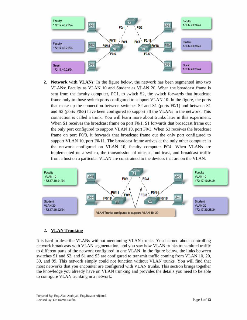
Prepared By: Eng.Alaa Arabiyat, Eng.Rawan Aljamal
Revised By: Dr. Ramzi Saifan Page 6 of 13
2. Network with VLANs: In the figure below, the network has been segmented into two
VLANs: Faculty as VLAN 10 and Student as VLAN 20. When the broadcast frame is
sent from the faculty computer, PC1, to switch S2, the switch forwards that broadcast
frame only to those switch ports configured to support VLAN 10. In the figure, the ports
that make up the connection between switches S2 and S1 (ports F0/1) and between S1
and S3 (ports F0/3) have been configured to support all the VLANs in the network. This
connection is called a trunk. You will learn more about trunks later in this experiment.
When S1 receives the broadcast frame on port F0/1, S1 forwards that broadcast frame out
the only port configured to support VLAN 10, port F0/3. When S3 receives the broadcast
frame on port F0/3, it forwards that broadcast frame out the only port configured to
support VLAN 10, port F0/11. The broadcast frame arrives at the only other computer in
the network configured on VLAN 10, faculty computer PC4. When VLANs are
implemented on a switch, the transmission of unicast, multicast, and broadcast traffic
from a host on a particular VLAN are constrained to the devices that are on the VLAN.
2. VLAN Trunking
It is hard to describe VLANs without mentioning VLAN trunks. You learned about controlling
network broadcasts with VLAN segmentation, and you saw how VLAN trunks transmitted traffic
to different parts of the network configured in one VLAN. In the figure below, the links between
switches S1 and S2, and S1 and S3 are configured to transmit traffic coming from VLAN 10, 20,
30, and 99. This network simply could not function without VLAN trunks. You will find that
most networks that you encounter are configured with VLAN trunks. This section brings together
the knowledge you already have on VLAN trunking and provides the details you need to be able
to configure VLAN trunking in a network.

Prepared By: Eng.Alaa Arabiyat, Eng.Rawan Aljamal
Revised By: Dr. Ramzi Saifan Page 7 of 13
Definition of a VLAN Trunk
A trunk is a point-to-point link between two network devices that carries more than one VLAN.
A VLAN trunk allows you to extend the VLANs across an entire network. Cisco supports IEEE
802.1Q for coordinating trunks on Fast Ethernet and Gigabit Ethernet interfaces. A VLAN trunk
does not belong to a specific VLAN; rather it is a conduit for VLANs between switches and
routers.
What Problem Does a Trunk Solve?
In the figure on the right, you see the standard topology used between switches S1 and S2, there
is a separate link for each subnet. There are four separate links connecting switches S1 and S2,
leaving three fewer ports to allocate to end-user devices. Each time a new subnetwork is
considered, a new link is needed for each switch in the network. The figure on the left shows a
VLAN trunk connecting switches S1 and S2 with a single physical link. This is the way a
network should be configured.
802.1Q Frame Tagging
Remember that switches are Layer 2 devices. They only use the Ethernet frame header
information to forward packets. The frame header does not contain information about which
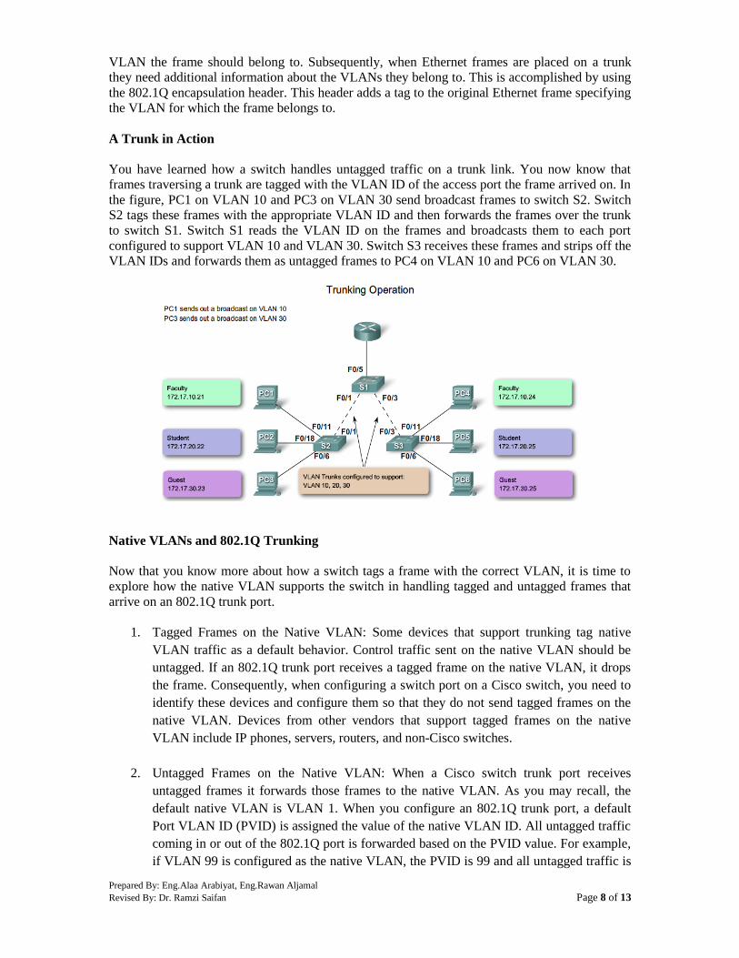
Prepared By: Eng.Alaa Arabiyat, Eng.Rawan Aljamal
Revised By: Dr. Ramzi Saifan Page 8 of 13
VLAN the frame should belong to. Subsequently, when Ethernet frames are placed on a trunk
they need additional information about the VLANs they belong to. This is accomplished by using
the 802.1Q encapsulation header. This header adds a tag to the original Ethernet frame specifying
the VLAN for which the frame belongs to.
A Trunk in Action
You have learned how a switch handles untagged traffic on a trunk link. You now know that
frames traversing a trunk are tagged with the VLAN ID of the access port the frame arrived on. In
the figure, PC1 on VLAN 10 and PC3 on VLAN 30 send broadcast frames to switch S2. Switch
S2 tags these frames with the appropriate VLAN ID and then forwards the frames over the trunk
to switch S1. Switch S1 reads the VLAN ID on the frames and broadcasts them to each port
configured to support VLAN 10 and VLAN 30. Switch S3 receives these frames and strips off the
VLAN IDs and forwards them as untagged frames to PC4 on VLAN 10 and PC6 on VLAN 30.
Native VLANs and 802.1Q Trunking
Now that you know more about how a switch tags a frame with the correct VLAN, it is time to
explore how the native VLAN supports the switch in handling tagged and untagged frames that
arrive on an 802.1Q trunk port.
1. Tagged Frames on the Native VLAN: Some devices that support trunking tag native
VLAN traffic as a default behavior. Control traffic sent on the native VLAN should be
untagged. If an 802.1Q trunk port receives a tagged frame on the native VLAN, it drops
the frame. Consequently, when configuring a switch port on a Cisco switch, you need to
identify these devices and configure them so that they do not send tagged frames on the
native VLAN. Devices from other vendors that support tagged frames on the native
VLAN include IP phones, servers, routers, and non-Cisco switches.
2. Untagged Frames on the Native VLAN: When a Cisco switch trunk port receives
untagged frames it forwards those frames to the native VLAN. As you may recall, the
default native VLAN is VLAN 1. When you configure an 802.1Q trunk port, a default
Port VLAN ID (PVID) is assigned the value of the native VLAN ID. All untagged traffic
coming in or out of the 802.1Q port is forwarded based on the PVID value. For example,
if VLAN 99 is configured as the native VLAN, the PVID is 99 and all untagged traffic is

Prepared By: Eng.Alaa Arabiyat, Eng.Rawan Aljamal
Revised By: Dr. Ramzi Saifan Page 9 of 13
forward to VLAN 99. If the native VLAN has not been reconfigured, the PVID value is
set to VLAN 1.
In this example, VLAN 99 will be configured as the native VLAN on port F0/1 on switch S1. Use
the Cisco IOS switchport trunk allowed vlan vlan-list command to specify the list of VLANs to
be allowed on the trunk link.
Using the show interfaces interface-id switchport command, you can quickly verify that you have
correctly reconfigured the native VLAN from VLAN 1 to VLAN 99. The highlighted output in
the screen capture indicates that the configuration was successful.
Note: If you did not specify a list of allowed VLANs on the trunk link, then ALL VLANs will be
allowed as shown in the last line in the figure below
3. Configuring VLANs and Trunks
In this experiment, you have already seen examples of the commands used to configure VLANs
and VLAN trunks. In this section, you will learn the key Cisco IOS commands needed to create,
delete, and verify VLANs and VLAN trunks. In the labs and activities, you will configure both
sides and verify that the link (VLAN or VLAN trunk) is configured correctly.
Use the following steps to configure and verify VLANs and trunks on a switched network:
1. Create the VLANs.
2. Assign switch ports to VLANs statically.
3. Verify VLAN configuration.
4. Enable Trunking on the inter-switch connections.
5. Verify trunk configuration.
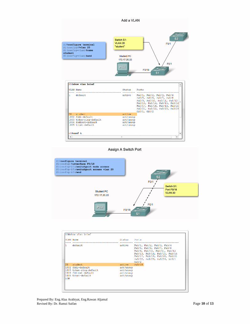
Prepared By: Eng.Alaa Arabiyat, Eng.Rawan Aljamal
Revised By: Dr. Ramzi Saifan Page 10 of 13

Prepared By: Eng.Alaa Arabiyat, Eng.Rawan Aljamal
Revised By: Dr. Ramzi Saifan Page 11 of 13

Prepared By: Eng.Alaa Arabiyat, Eng.Rawan Aljamal
Revised By: Dr. Ramzi Saifan Page 12 of 13
Verify trunk configuration
4. Common Problems with Trunks
In this topic, you learn about common VLAN and trunking issues, which usually are associated
with incorrect configurations. When you are configuring VLANs and trunks on a switched
infrastructure, these types of configuration errors are most common in the following order:
Native VLAN mismatches - Trunk ports are configured with different native VLANs, for
example, if one port has defined VLAN 99 as the native VLAN and the other trunk port has
defined VLAN 100 as the native VLAN. This configuration error generates console notifications,
causes control and management traffic to be misdirected and, as you have learned, poses a
security risk.
Trunk mode mismatches - One trunk port is configured with trunk mode "off" and the other
with trunk mode "on". This configuration error causes the trunk link to stop working.
S1#show interface trunk
Port Mode Encapsulation Status Native vlan
Fa0/1 on 802.1q trunking 99
Port Vlans allowed on trunk
Fa0/1 1-1005
Port Vlans allowed and active in management domain
Fa0/1 1,10,20,30,99,1002,1003,1004,1005
Port Vlans in spanning tree forwarding state and not pruned
Fa0/1 1,10,20,30,99,1002,1003,1004,1005

Prepared By: Eng.Alaa Arabiyat, Eng.Rawan Aljamal
Revised By: Dr. Ramzi Saifan Page 13 of 13
VLANs and IP Subnets - End user devices configured with incorrect IP addresses will not have
network connectivity. Each VLAN is a logically separate IP subnetwork. Devices within the
VLAN must be configured with the correct IP settings.
Allowed VLANs on trunks - The list of allowed VLANs on a trunk has not been updated with
the current VLAN trunking requirements. In this situation, unexpected traffic or no traffic is
being sent over the trunk.
If you have discovered an issue with a VLAN or trunk and do not know what the problem is, start
your troubleshooting by examining the trunks for a native VLAN mismatch and then work down
the list.
Procedure:
You can find the lab problem sheet and the packet tracer activities on the lab website.
Reference:
CCNA Routing and Switching - Cisco Networking Academy.
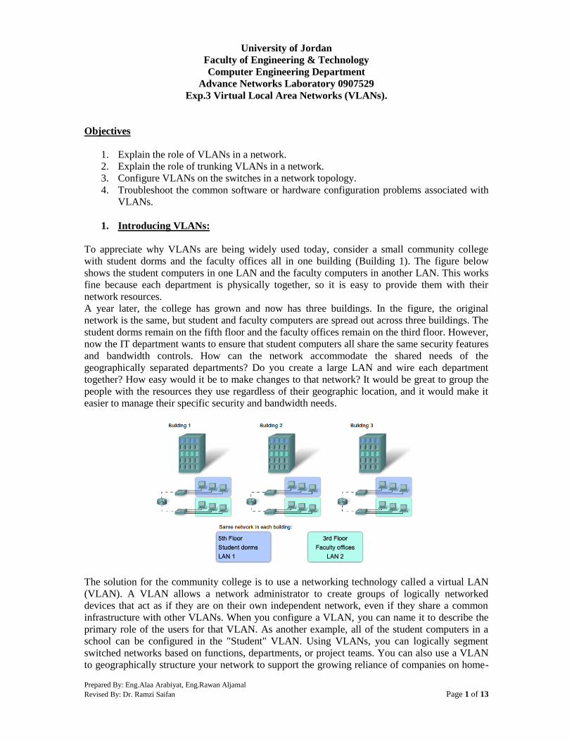
Prepared By: Eng.Alaa Arabiyat, Eng.Rawan Aljamal
Revised By: Dr. Ramzi Saifan Page 1 of 13
University of Jordan
Faculty of Engineering & Technology
Computer Engineering Department
Advance Networks Laboratory 0907529
Exp.3 Virtual Local Area Networks (VLANs).
Objectives
1. Explain the role of VLANs in a network.
2. Explain the role of trunking VLANs in a network.
3. Configure VLANs on the switches in a network topology.
4. Troubleshoot the common software or hardware configuration problems associated with
VLANs.
1. Introducing VLANs:
To appreciate why VLANs are being widely used today, consider a small community college
with student dorms and the faculty offices all in one building (Building 1). The figure below
shows the student computers in one LAN and the faculty computers in another LAN. This works
fine because each department is physically together, so it is easy to provide them with their
network resources.
A year later, the college has grown and now has three buildings. In the figure, the original
network is the same, but student and faculty computers are spread out across three buildings. The
student dorms remain on the fifth floor and the faculty offices remain on the third floor. However,
now the IT department wants to ensure that student computers all share the same security features
and bandwidth controls. How can the network accommodate the shared needs of the
geographically separated departments? Do you create a large LAN and wire each department
together? How easy would it be to make changes to that network? It would be great to group the
people with the resources they use regardless of their geographic location, and it would make it
easier to manage their specific security and bandwidth needs.
The solution for the community college is to use a networking technology called a virtual LAN
(VLAN). A VLAN allows a network administrator to create groups of logically networked
devices that act as if they are on their own independent network, even if they share a common
infrastructure with other VLANs. When you configure a VLAN, you can name it to describe the
primary role of the users for that VLAN. As another example, all of the student computers in a
school can be configured in the "Student" VLAN. Using VLANs, you can logically segment
switched networks based on functions, departments, or project teams. You can also use a VLAN
to geographically structure your network to support the growing reliance of companies on home-
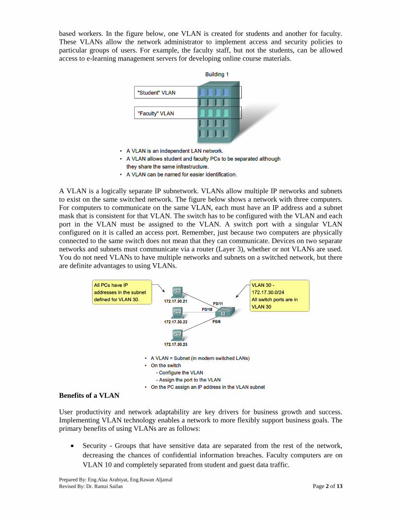
Prepared By: Eng.Alaa Arabiyat, Eng.Rawan Aljamal
Revised By: Dr. Ramzi Saifan Page 2 of 13
based workers. In the figure below, one VLAN is created for students and another for faculty.
These VLANs allow the network administrator to implement access and security policies to
particular groups of users. For example, the faculty staff, but not the students, can be allowed
access to e-learning management servers for developing online course materials.
A VLAN is a logically separate IP subnetwork. VLANs allow multiple IP networks and subnets
to exist on the same switched network. The figure below shows a network with three computers.
For computers to communicate on the same VLAN, each must have an IP address and a subnet
mask that is consistent for that VLAN. The switch has to be configured with the VLAN and each
port in the VLAN must be assigned to the VLAN. A switch port with a singular VLAN
configured on it is called an access port. Remember, just because two computers are physically
connected to the same switch does not mean that they can communicate. Devices on two separate
networks and subnets must communicate via a router (Layer 3), whether or not VLANs are used.
You do not need VLANs to have multiple networks and subnets on a switched network, but there
are definite advantages to using VLANs.
Benefits of a VLAN
User productivity and network adaptability are key drivers for business growth and success.
Implementing VLAN technology enables a network to more flexibly support business goals. The
primary benefits of using VLANs are as follows:
Security - Groups that have sensitive data are separated from the rest of the network,
decreasing the chances of confidential information breaches. Faculty computers are on
VLAN 10 and completely separated from student and guest data traffic.
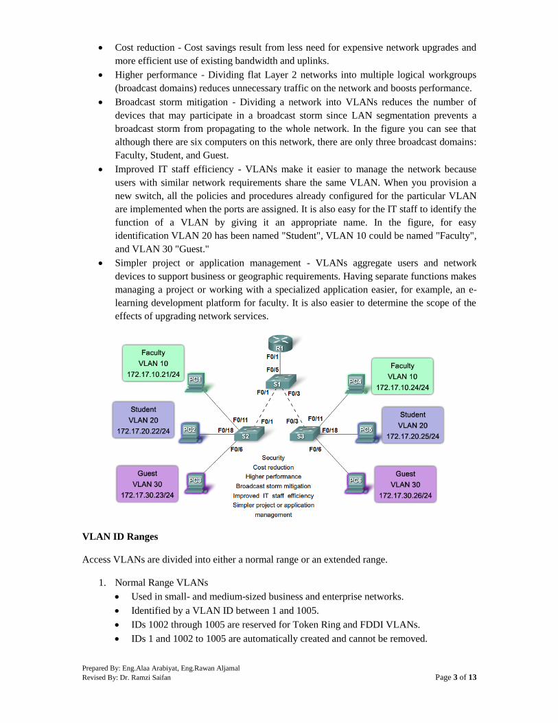
Prepared By: Eng.Alaa Arabiyat, Eng.Rawan Aljamal
Revised By: Dr. Ramzi Saifan Page 3 of 13
Cost reduction - Cost savings result from less need for expensive network upgrades and
more efficient use of existing bandwidth and uplinks.
Higher performance - Dividing flat Layer 2 networks into multiple logical workgroups
(broadcast domains) reduces unnecessary traffic on the network and boosts performance.
Broadcast storm mitigation - Dividing a network into VLANs reduces the number of
devices that may participate in a broadcast storm since LAN segmentation prevents a
broadcast storm from propagating to the whole network. In the figure you can see that
although there are six computers on this network, there are only three broadcast domains:
Faculty, Student, and Guest.
Improved IT staff efficiency - VLANs make it easier to manage the network because
users with similar network requirements share the same VLAN. When you provision a
new switch, all the policies and procedures already configured for the particular VLAN
are implemented when the ports are assigned. It is also easy for the IT staff to identify the
function of a VLAN by giving it an appropriate name. In the figure, for easy
identification VLAN 20 has been named "Student", VLAN 10 could be named "Faculty",
and VLAN 30 "Guest."
Simpler project or application management - VLANs aggregate users and network
devices to support business or geographic requirements. Having separate functions makes
managing a project or working with a specialized application easier, for example, an e-
learning development platform for faculty. It is also easier to determine the scope of the
effects of upgrading network services.
VLAN ID Ranges
Access VLANs are divided into either a normal range or an extended range.
1. Normal Range VLANs
Used in small- and medium-sized business and enterprise networks.
Identified by a VLAN ID between 1 and 1005.
IDs 1002 through 1005 are reserved for Token Ring and FDDI VLANs.
IDs 1 and 1002 to 1005 are automatically created and cannot be removed.
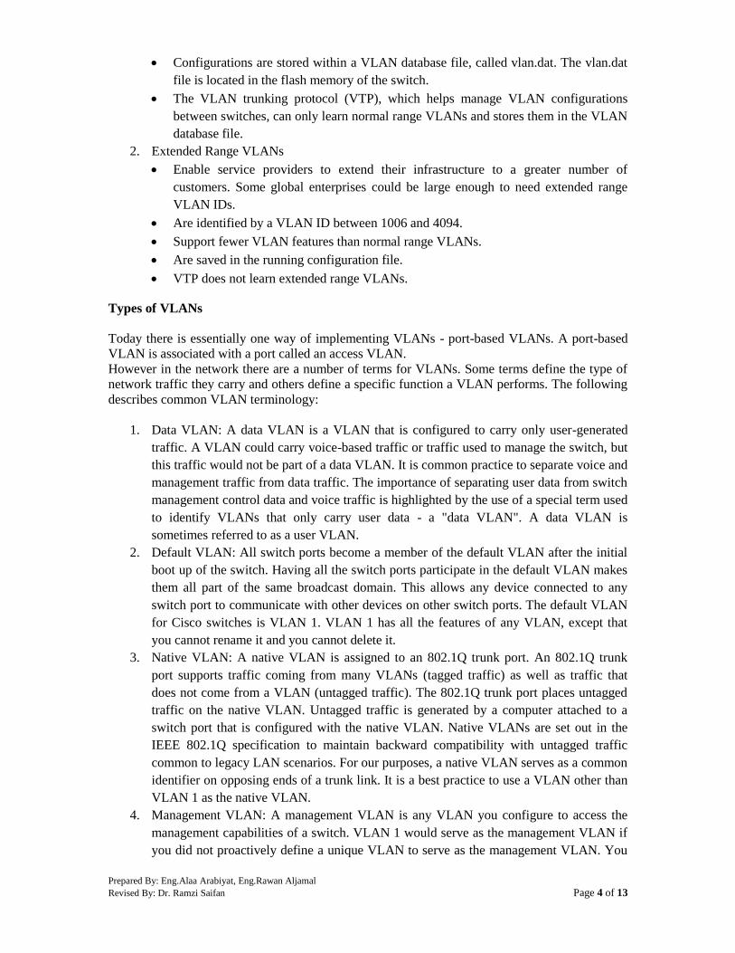
Prepared By: Eng.Alaa Arabiyat, Eng.Rawan Aljamal
Revised By: Dr. Ramzi Saifan Page 4 of 13
Configurations are stored within a VLAN database file, called vlan.dat. The vlan.dat
file is located in the flash memory of the switch.
The VLAN trunking protocol (VTP), which helps manage VLAN configurations
between switches, can only learn normal range VLANs and stores them in the VLAN
database file.
2. Extended Range VLANs
Enable service providers to extend their infrastructure to a greater number of
customers. Some global enterprises could be large enough to need extended range
VLAN IDs.
Are identified by a VLAN ID between 1006 and 4094.
Support fewer VLAN features than normal range VLANs.
Are saved in the running configuration file.
VTP does not learn extended range VLANs.
Types of VLANs
Today there is essentially one way of implementing VLANs - port-based VLANs. A port-based
VLAN is associated with a port called an access VLAN.
However in the network there are a number of terms for VLANs. Some terms define the type of
network traffic they carry and others define a specific function a VLAN performs. The following
describes common VLAN terminology:
1. Data VLAN: A data VLAN is a VLAN that is configured to carry only user-generated
traffic. A VLAN could carry voice-based traffic or traffic used to manage the switch, but
this traffic would not be part of a data VLAN. It is common practice to separate voice and
management traffic from data traffic. The importance of separating user data from switch
management control data and voice traffic is highlighted by the use of a special term used
to identify VLANs that only carry user data - a "data VLAN". A data VLAN is
sometimes referred to as a user VLAN.
2. Default VLAN: All switch ports become a member of the default VLAN after the initial
boot up of the switch. Having all the switch ports participate in the default VLAN makes
them all part of the same broadcast domain. This allows any device connected to any
switch port to communicate with other devices on other switch ports. The default VLAN
for Cisco switches is VLAN 1. VLAN 1 has all the features of any VLAN, except that
you cannot rename it and you cannot delete it.
3. Native VLAN: A native VLAN is assigned to an 802.1Q trunk port. An 802.1Q trunk
port supports traffic coming from many VLANs (tagged traffic) as well as traffic that
does not come from a VLAN (untagged traffic). The 802.1Q trunk port places untagged
traffic on the native VLAN. Untagged traffic is generated by a computer attached to a
switch port that is configured with the native VLAN. Native VLANs are set out in the
IEEE 802.1Q specification to maintain backward compatibility with untagged traffic
common to legacy LAN scenarios. For our purposes, a native VLAN serves as a common
identifier on opposing ends of a trunk link. It is a best practice to use a VLAN other than
VLAN 1 as the native VLAN.
4. Management VLAN: A management VLAN is any VLAN you configure to access the
management capabilities of a switch. VLAN 1 would serve as the management VLAN if
you did not proactively define a unique VLAN to serve as the management VLAN. You
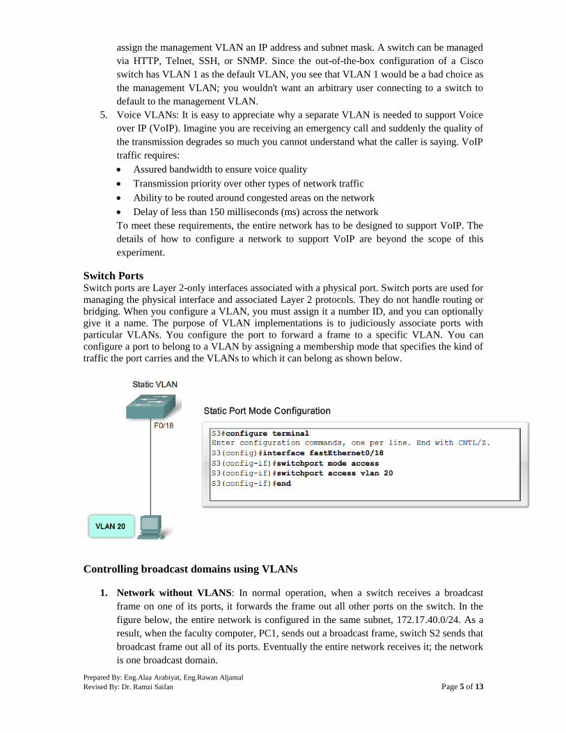
Prepared By: Eng.Alaa Arabiyat, Eng.Rawan Aljamal
Revised By: Dr. Ramzi Saifan Page 5 of 13
assign the management VLAN an IP address and subnet mask. A switch can be managed
via HTTP, Telnet, SSH, or SNMP. Since the out-of-the-box configuration of a Cisco
switch has VLAN 1 as the default VLAN, you see that VLAN 1 would be a bad choice as
the management VLAN; you wouldn't want an arbitrary user connecting to a switch to
default to the management VLAN.
5. Voice VLANs: It is easy to appreciate why a separate VLAN is needed to support Voice
over IP (VoIP). Imagine you are receiving an emergency call and suddenly the quality of
the transmission degrades so much you cannot understand what the caller is saying. VoIP
traffic requires:
Assured bandwidth to ensure voice quality
Transmission priority over other types of network traffic
Ability to be routed around congested areas on the network
Delay of less than 150 milliseconds (ms) across the network
To meet these requirements, the entire network has to be designed to support VoIP. The
details of how to configure a network to support VoIP are beyond the scope of this
experiment.
Switch Ports Switch ports are Layer 2-only interfaces associated with a physical port. Switch ports are used for
managing the physical interface and associated Layer 2 protocols. They do not handle routing or
bridging. When you configure a VLAN, you must assign it a number ID, and you can optionally
give it a name. The purpose of VLAN implementations is to judiciously associate ports with
particular VLANs. You configure the port to forward a frame to a specific VLAN. You can
configure a port to belong to a VLAN by assigning a membership mode that specifies the kind of
traffic the port carries and the VLANs to which it can belong as shown below.
Controlling broadcast domains using VLANs
1. Network without VLANS: In normal operation, when a switch receives a broadcast
frame on one of its ports, it forwards the frame out all other ports on the switch. In the
figure below, the entire network is configured in the same subnet, 172.17.40.0/24. As a
result, when the faculty computer, PC1, sends out a broadcast frame, switch S2 sends that
broadcast frame out all of its ports. Eventually the entire network receives it; the network
is one broadcast domain.

Prepared By: Eng.Alaa Arabiyat, Eng.Rawan Aljamal
Revised By: Dr. Ramzi Saifan Page 6 of 13
2. Network with VLANs: In the figure below, the network has been segmented into two
VLANs: Faculty as VLAN 10 and Student as VLAN 20. When the broadcast frame is
sent from the faculty computer, PC1, to switch S2, the switch forwards that broadcast
frame only to those switch ports configured to support VLAN 10. In the figure, the ports
that make up the connection between switches S2 and S1 (ports F0/1) and between S1
and S3 (ports F0/3) have been configured to support all the VLANs in the network. This
connection is called a trunk. You will learn more about trunks later in this experiment.
When S1 receives the broadcast frame on port F0/1, S1 forwards that broadcast frame out
the only port configured to support VLAN 10, port F0/3. When S3 receives the broadcast
frame on port F0/3, it forwards that broadcast frame out the only port configured to
support VLAN 10, port F0/11. The broadcast frame arrives at the only other computer in
the network configured on VLAN 10, faculty computer PC4. When VLANs are
implemented on a switch, the transmission of unicast, multicast, and broadcast traffic
from a host on a particular VLAN are constrained to the devices that are on the VLAN.
2. VLAN Trunking
It is hard to describe VLANs without mentioning VLAN trunks. You learned about controlling
network broadcasts with VLAN segmentation, and you saw how VLAN trunks transmitted traffic
to different parts of the network configured in one VLAN. In the figure below, the links between
switches S1 and S2, and S1 and S3 are configured to transmit traffic coming from VLAN 10, 20,
30, and 99. This network simply could not function without VLAN trunks. You will find that
most networks that you encounter are configured with VLAN trunks. This section brings together
the knowledge you already have on VLAN trunking and provides the details you need to be able
to configure VLAN trunking in a network.
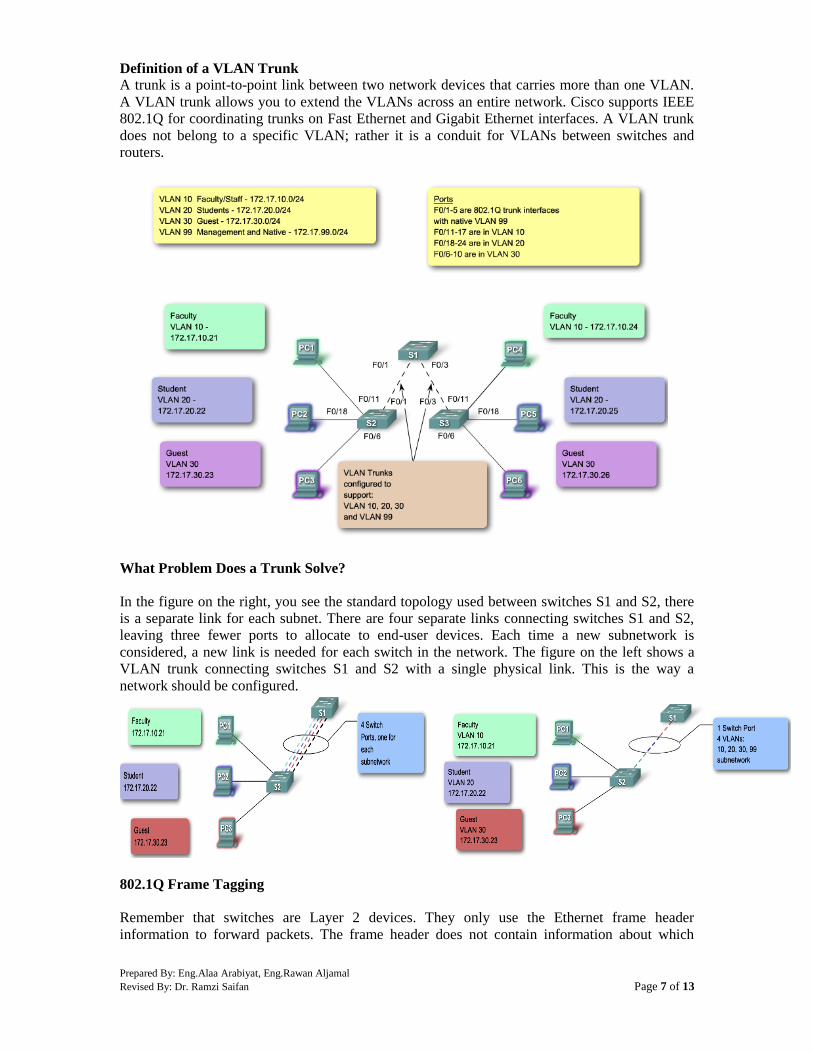
Prepared By: Eng.Alaa Arabiyat, Eng.Rawan Aljamal
Revised By: Dr. Ramzi Saifan Page 7 of 13
Definition of a VLAN Trunk
A trunk is a point-to-point link between two network devices that carries more than one VLAN.
A VLAN trunk allows you to extend the VLANs across an entire network. Cisco supports IEEE
802.1Q for coordinating trunks on Fast Ethernet and Gigabit Ethernet interfaces. A VLAN trunk
does not belong to a specific VLAN; rather it is a conduit for VLANs between switches and
routers.
What Problem Does a Trunk Solve?
In the figure on the right, you see the standard topology used between switches S1 and S2, there
is a separate link for each subnet. There are four separate links connecting switches S1 and S2,
leaving three fewer ports to allocate to end-user devices. Each time a new subnetwork is
considered, a new link is needed for each switch in the network. The figure on the left shows a
VLAN trunk connecting switches S1 and S2 with a single physical link. This is the way a
network should be configured.
802.1Q Frame Tagging
Remember that switches are Layer 2 devices. They only use the Ethernet frame header
information to forward packets. The frame header does not contain information about which

Prepared By: Eng.Alaa Arabiyat, Eng.Rawan Aljamal
Revised By: Dr. Ramzi Saifan Page 8 of 13
VLAN the frame should belong to. Subsequently, when Ethernet frames are placed on a trunk
they need additional information about the VLANs they belong to. This is accomplished by using
the 802.1Q encapsulation header. This header adds a tag to the original Ethernet frame specifying
the VLAN for which the frame belongs to.
A Trunk in Action
You have learned how a switch handles untagged traffic on a trunk link. You now know that
frames traversing a trunk are tagged with the VLAN ID of the access port the frame arrived on. In
the figure, PC1 on VLAN 10 and PC3 on VLAN 30 send broadcast frames to switch S2. Switch
S2 tags these frames with the appropriate VLAN ID and then forwards the frames over the trunk
to switch S1. Switch S1 reads the VLAN ID on the frames and broadcasts them to each port
configured to support VLAN 10 and VLAN 30. Switch S3 receives these frames and strips off the
VLAN IDs and forwards them as untagged frames to PC4 on VLAN 10 and PC6 on VLAN 30.
Native VLANs and 802.1Q Trunking
Now that you know more about how a switch tags a frame with the correct VLAN, it is time to
explore how the native VLAN supports the switch in handling tagged and untagged frames that
arrive on an 802.1Q trunk port.
1. Tagged Frames on the Native VLAN: Some devices that support trunking tag native
VLAN traffic as a default behavior. Control traffic sent on the native VLAN should be
untagged. If an 802.1Q trunk port receives a tagged frame on the native VLAN, it drops
the frame. Consequently, when configuring a switch port on a Cisco switch, you need to
identify these devices and configure them so that they do not send tagged frames on the
native VLAN. Devices from other vendors that support tagged frames on the native
VLAN include IP phones, servers, routers, and non-Cisco switches.
2. Untagged Frames on the Native VLAN: When a Cisco switch trunk port receives
untagged frames it forwards those frames to the native VLAN. As you may recall, the
default native VLAN is VLAN 1. When you configure an 802.1Q trunk port, a default
Port VLAN ID (PVID) is assigned the value of the native VLAN ID. All untagged traffic
coming in or out of the 802.1Q port is forwarded based on the PVID value. For example,
if VLAN 99 is configured as the native VLAN, the PVID is 99 and all untagged traffic is
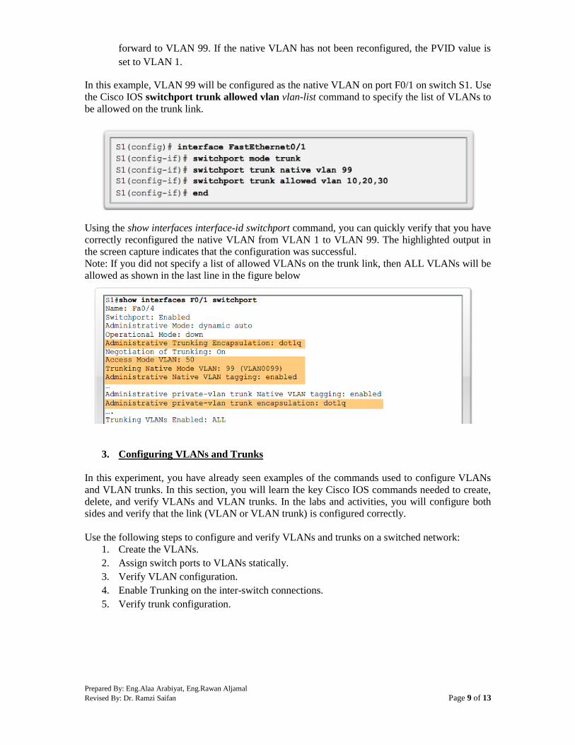
Prepared By: Eng.Alaa Arabiyat, Eng.Rawan Aljamal
Revised By: Dr. Ramzi Saifan Page 9 of 13
forward to VLAN 99. If the native VLAN has not been reconfigured, the PVID value is
set to VLAN 1.
In this example, VLAN 99 will be configured as the native VLAN on port F0/1 on switch S1. Use
the Cisco IOS switchport trunk allowed vlan vlan-list command to specify the list of VLANs to
be allowed on the trunk link.
Using the show interfaces interface-id switchport command, you can quickly verify that you have
correctly reconfigured the native VLAN from VLAN 1 to VLAN 99. The highlighted output in
the screen capture indicates that the configuration was successful.
Note: If you did not specify a list of allowed VLANs on the trunk link, then ALL VLANs will be
allowed as shown in the last line in the figure below
3. Configuring VLANs and Trunks
In this experiment, you have already seen examples of the commands used to configure VLANs
and VLAN trunks. In this section, you will learn the key Cisco IOS commands needed to create,
delete, and verify VLANs and VLAN trunks. In the labs and activities, you will configure both
sides and verify that the link (VLAN or VLAN trunk) is configured correctly.
Use the following steps to configure and verify VLANs and trunks on a switched network:
1. Create the VLANs.
2. Assign switch ports to VLANs statically.
3. Verify VLAN configuration.
4. Enable Trunking on the inter-switch connections.
5. Verify trunk configuration.

Prepared By: Eng.Alaa Arabiyat, Eng.Rawan Aljamal
Revised By: Dr. Ramzi Saifan Page 10 of 13
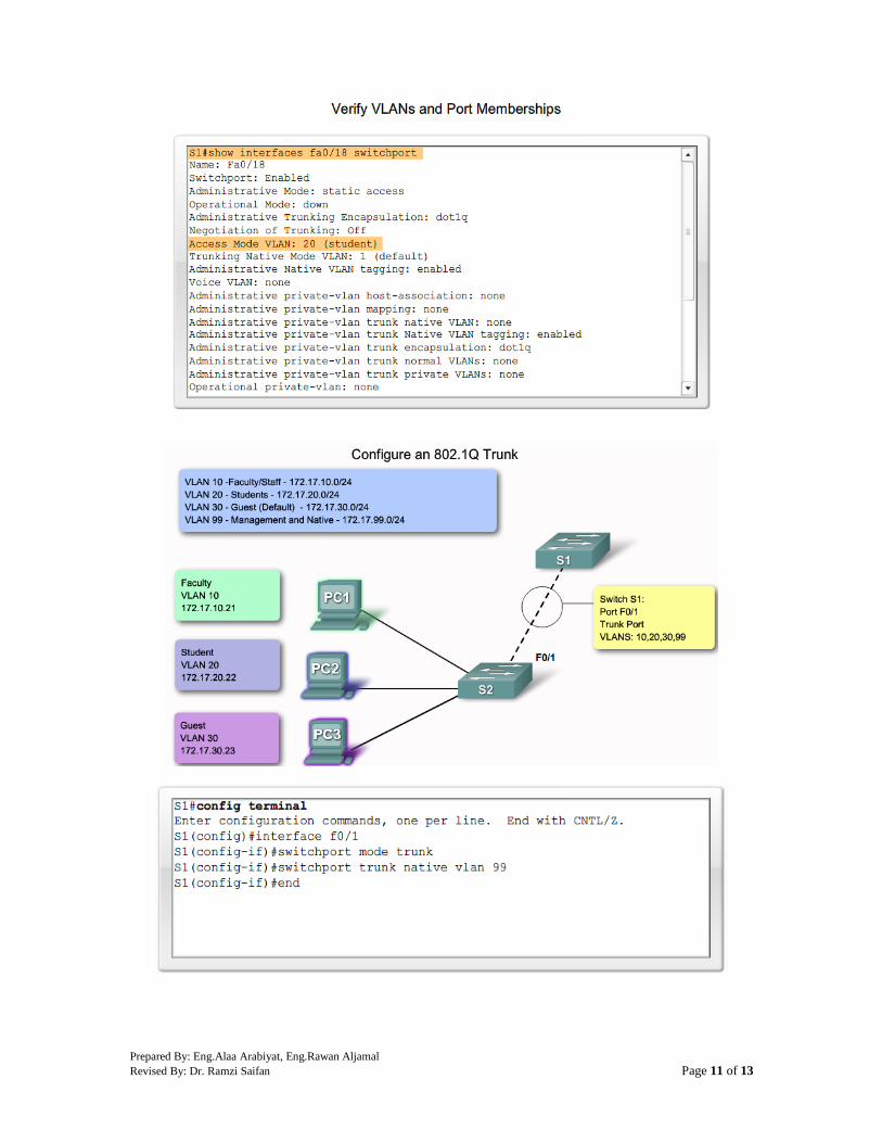
Prepared By: Eng.Alaa Arabiyat, Eng.Rawan Aljamal
Revised By: Dr. Ramzi Saifan Page 11 of 13
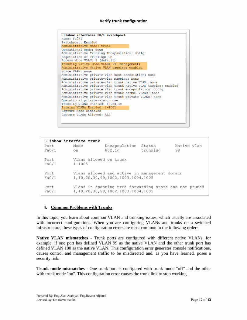
Prepared By: Eng.Alaa Arabiyat, Eng.Rawan Aljamal
Revised By: Dr. Ramzi Saifan Page 12 of 13
Verify trunk configuration
4. Common Problems with Trunks
In this topic, you learn about common VLAN and trunking issues, which usually are associated
with incorrect configurations. When you are configuring VLANs and trunks on a switched
infrastructure, these types of configuration errors are most common in the following order:
Native VLAN mismatches - Trunk ports are configured with different native VLANs, for
example, if one port has defined VLAN 99 as the native VLAN and the other trunk port has
defined VLAN 100 as the native VLAN. This configuration error generates console notifications,
causes control and management traffic to be misdirected and, as you have learned, poses a
security risk.
Trunk mode mismatches - One trunk port is configured with trunk mode "off" and the other
with trunk mode "on". This configuration error causes the trunk link to stop working.
S1#show interface trunk
Port Mode Encapsulation Status Native vlan
Fa0/1 on 802.1q trunking 99
Port Vlans allowed on trunk
Fa0/1 1-1005
Port Vlans allowed and active in management domain
Fa0/1 1,10,20,30,99,1002,1003,1004,1005
Port Vlans in spanning tree forwarding state and not pruned
Fa0/1 1,10,20,30,99,1002,1003,1004,1005
Prepared By: Eng.Alaa Arabiyat, Eng.Rawan Aljamal
Revised By: Dr. Ramzi Saifan Page 13 of 13
VLANs and IP Subnets - End user devices configured with incorrect IP addresses will not have
network connectivity. Each VLAN is a logically separate IP subnetwork. Devices within the
VLAN must be configured with the correct IP settings.
Allowed VLANs on trunks - The list of allowed VLANs on a trunk has not been updated with
the current VLAN trunking requirements. In this situation, unexpected traffic or no traffic is
being sent over the trunk.
If you have discovered an issue with a VLAN or trunk and do not know what the problem is, start
your troubleshooting by examining the trunks for a native VLAN mismatch and then work down
the list.
Procedure:
You can find the lab problem sheet and the packet tracer activities on the lab website.
Reference:
CCNA Routing and Switching - Cisco Networking Academy.
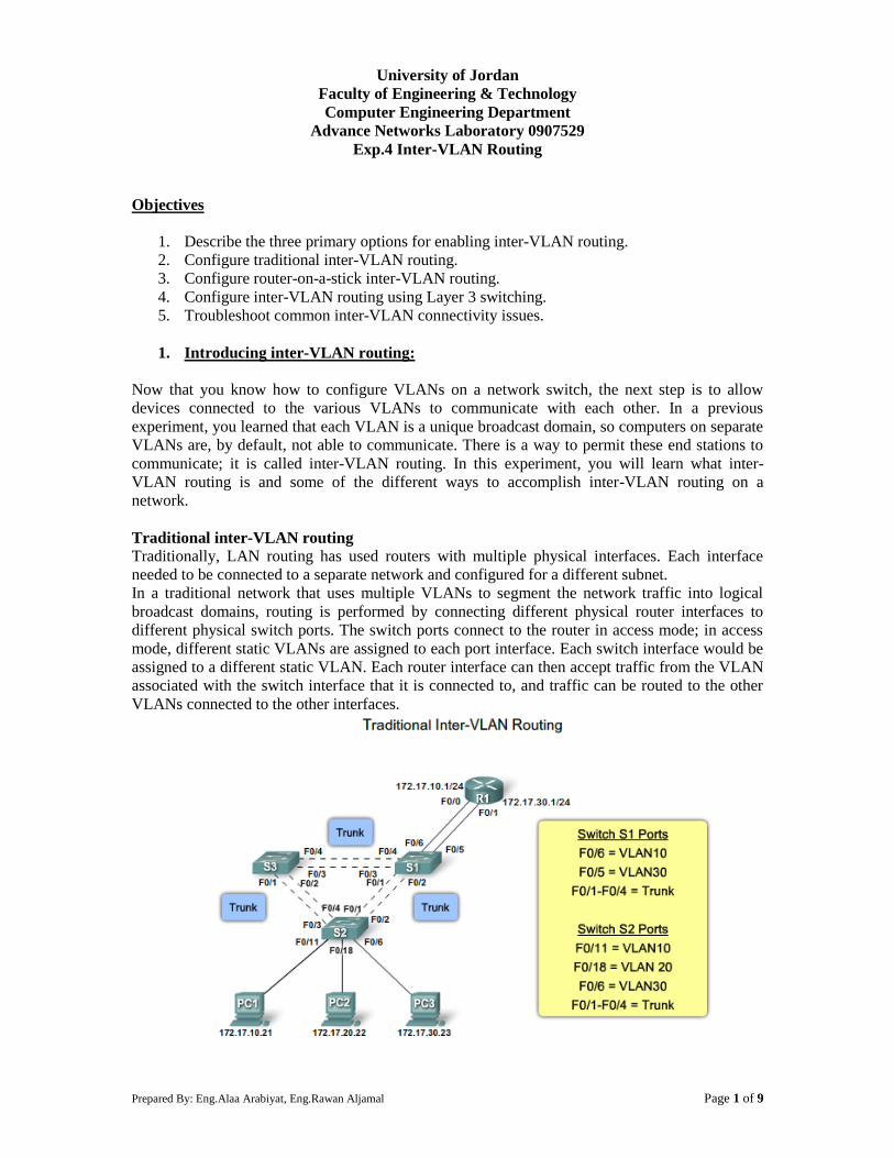
Prepared By: Eng.Alaa Arabiyat, Eng.Rawan Aljamal Page 1 of 9
University of Jordan
Faculty of Engineering & Technology
Computer Engineering Department
Advance Networks Laboratory 0907529
Exp.4 Inter-VLAN Routing
Objectives
1. Describe the three primary options for enabling inter-VLAN routing.
2. Configure traditional inter-VLAN routing.
3. Configure router-on-a-stick inter-VLAN routing.
4. Configure inter-VLAN routing using Layer 3 switching.
5. Troubleshoot common inter-VLAN connectivity issues.
1. Introducing inter-VLAN routing:
Now that you know how to configure VLANs on a network switch, the next step is to allow
devices connected to the various VLANs to communicate with each other. In a previous
experiment, you learned that each VLAN is a unique broadcast domain, so computers on separate
VLANs are, by default, not able to communicate. There is a way to permit these end stations to
communicate; it is called inter-VLAN routing. In this experiment, you will learn what inter-
VLAN routing is and some of the different ways to accomplish inter-VLAN routing on a
network.
Traditional inter-VLAN routing
Traditionally, LAN routing has used routers with multiple physical interfaces. Each interface
needed to be connected to a separate network and configured for a different subnet.
In a traditional network that uses multiple VLANs to segment the network traffic into logical
broadcast domains, routing is performed by connecting different physical router interfaces to
different physical switch ports. The switch ports connect to the router in access mode; in access
mode, different static VLANs are assigned to each port interface. Each switch interface would be
assigned to a different static VLAN. Each router interface can then accept traffic from the VLAN
associated with the switch interface that it is connected to, and traffic can be routed to the other
VLANs connected to the other interfaces.
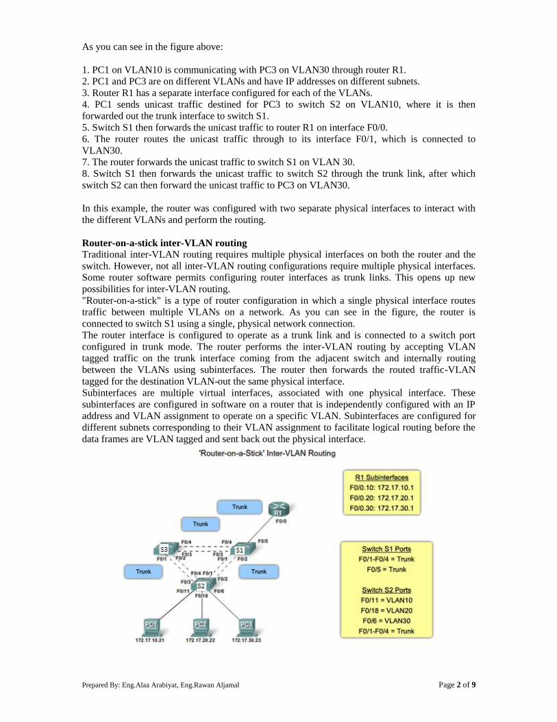
Prepared By: Eng.Alaa Arabiyat, Eng.Rawan Aljamal Page 2 of 9
As you can see in the figure above:
1. PC1 on VLAN10 is communicating with PC3 on VLAN30 through router R1.
2. PC1 and PC3 are on different VLANs and have IP addresses on different subnets.
3. Router R1 has a separate interface configured for each of the VLANs.
4. PC1 sends unicast traffic destined for PC3 to switch S2 on VLAN10, where it is then
forwarded out the trunk interface to switch S1.
5. Switch S1 then forwards the unicast traffic to router R1 on interface F0/0.
6. The router routes the unicast traffic through to its interface F0/1, which is connected to
VLAN30.
7. The router forwards the unicast traffic to switch S1 on VLAN 30.
8. Switch S1 then forwards the unicast traffic to switch S2 through the trunk link, after which
switch S2 can then forward the unicast traffic to PC3 on VLAN30.
In this example, the router was configured with two separate physical interfaces to interact with
the different VLANs and perform the routing.
Router-on-a-stick inter-VLAN routing
Traditional inter-VLAN routing requires multiple physical interfaces on both the router and the
switch. However, not all inter-VLAN routing configurations require multiple physical interfaces.
Some router software permits configuring router interfaces as trunk links. This opens up new
possibilities for inter-VLAN routing.
"Router-on-a-stick" is a type of router configuration in which a single physical interface routes
traffic between multiple VLANs on a network. As you can see in the figure, the router is
connected to switch S1 using a single, physical network connection.
The router interface is configured to operate as a trunk link and is connected to a switch port
configured in trunk mode. The router performs the inter-VLAN routing by accepting VLAN
tagged traffic on the trunk interface coming from the adjacent switch and internally routing
between the VLANs using subinterfaces. The router then forwards the routed traffic-VLAN
tagged for the destination VLAN-out the same physical interface.
Subinterfaces are multiple virtual interfaces, associated with one physical interface. These
subinterfaces are configured in software on a router that is independently configured with an IP
address and VLAN assignment to operate on a specific VLAN. Subinterfaces are configured for
different subnets corresponding to their VLAN assignment to facilitate logical routing before the
data frames are VLAN tagged and sent back out the physical interface.
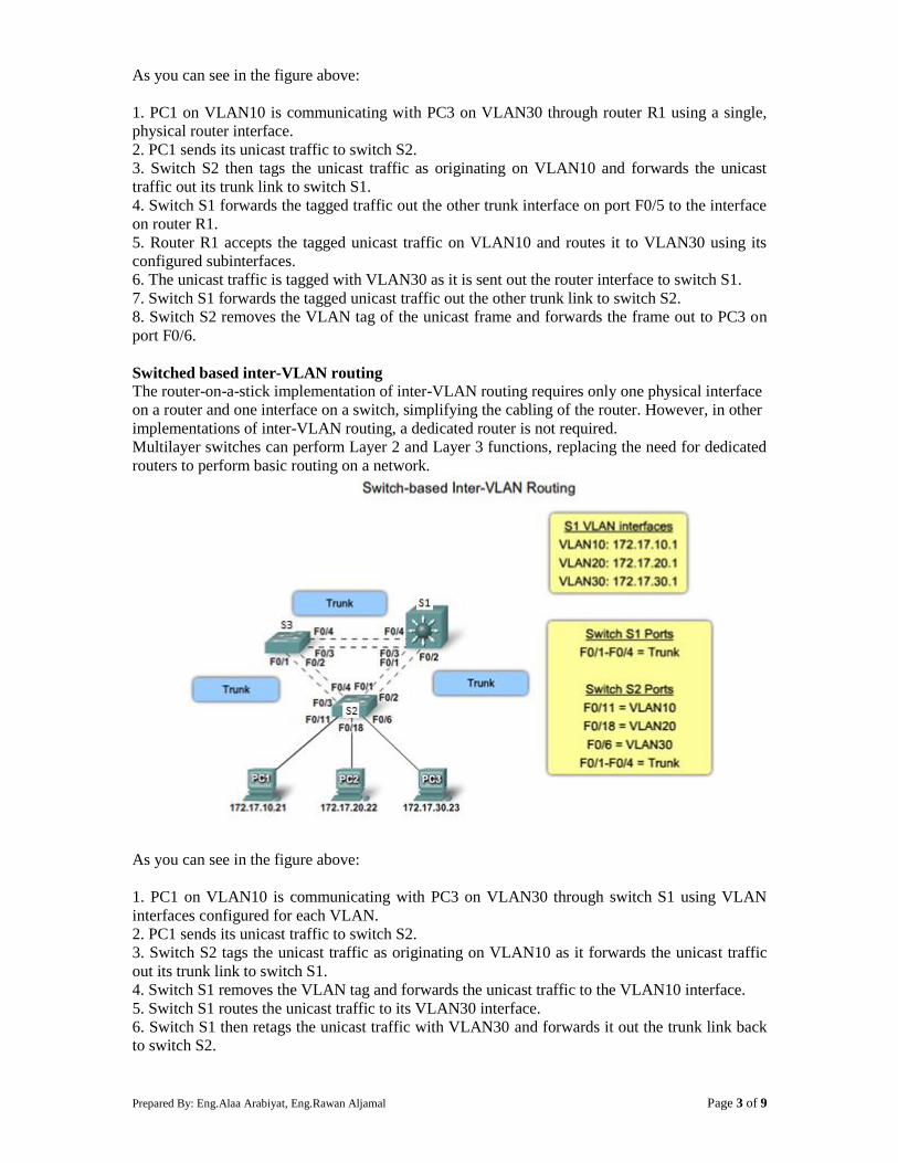
Prepared By: Eng.Alaa Arabiyat, Eng.Rawan Aljamal Page 3 of 9
As you can see in the figure above:
1. PC1 on VLAN10 is communicating with PC3 on VLAN30 through router R1 using a single,
physical router interface.
2. PC1 sends its unicast traffic to switch S2.
3. Switch S2 then tags the unicast traffic as originating on VLAN10 and forwards the unicast
traffic out its trunk link to switch S1.
4. Switch S1 forwards the tagged traffic out the other trunk interface on port F0/5 to the interface
on router R1.
5. Router R1 accepts the tagged unicast traffic on VLAN10 and routes it to VLAN30 using its
configured subinterfaces.
6. The unicast traffic is tagged with VLAN30 as it is sent out the router interface to switch S1.
7. Switch S1 forwards the tagged unicast traffic out the other trunk link to switch S2.
8. Switch S2 removes the VLAN tag of the unicast frame and forwards the frame out to PC3 on
port F0/6.
Switched based inter-VLAN routing
The router-on-a-stick implementation of inter-VLAN routing requires only one physical interface
on a router and one interface on a switch, simplifying the cabling of the router. However, in other
implementations of inter-VLAN routing, a dedicated router is not required.
Multilayer switches can perform Layer 2 and Layer 3 functions, replacing the need for dedicated
routers to perform basic routing on a network.
As you can see in the figure above:
1. PC1 on VLAN10 is communicating with PC3 on VLAN30 through switch S1 using VLAN
interfaces configured for each VLAN.
2. PC1 sends its unicast traffic to switch S2.
3. Switch S2 tags the unicast traffic as originating on VLAN10 as it forwards the unicast traffic
out its trunk link to switch S1.
4. Switch S1 removes the VLAN tag and forwards the unicast traffic to the VLAN10 interface.
5. Switch S1 routes the unicast traffic to its VLAN30 interface.
6. Switch S1 then retags the unicast traffic with VLAN30 and forwards it out the trunk link back
to switch S2.
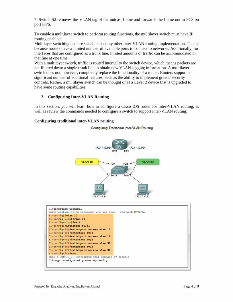
Prepared By: Eng.Alaa Arabiyat, Eng.Rawan Aljamal Page 4 of 9
7. Switch S2 removes the VLAN tag of the unicast frame and forwards the frame out to PC3 on
port F0/6.
To enable a multilayer switch to perform routing functions, the multilayer switch must have IP
routing enabled.
Multilayer switching is more scalable than any other inter-VLAN routing implementation. This is
because routers have a limited number of available ports to connect to networks. Additionally, for
interfaces that are configured as a trunk line, limited amounts of traffic can be accommodated on
that line at one time.
With a multilayer switch, traffic is routed internal to the switch device, which means packets are
not filtered down a single trunk line to obtain new VLAN-tagging information. A multilayer
switch does not, however, completely replace the functionality of a router. Routers support a
significant number of additional features, such as the ability to implement greater security
controls. Rather, a multilayer switch can be thought of as a Layer 2 device that is upgraded to
have some routing capabilities.
2. Configuring Inter-VLAN Routing
In this section, you will learn how to configure a Cisco IOS router for inter-VLAN routing, as
well as review the commands needed to configure a switch to support inter-VLAN routing.
Configuring traditional inter-VLAN routing

Prepared By: Eng.Alaa Arabiyat, Eng.Rawan Aljamal Page 5 of 9
Routing Table and verification:
Configuring router-on-a-stick inter-VLAN routing
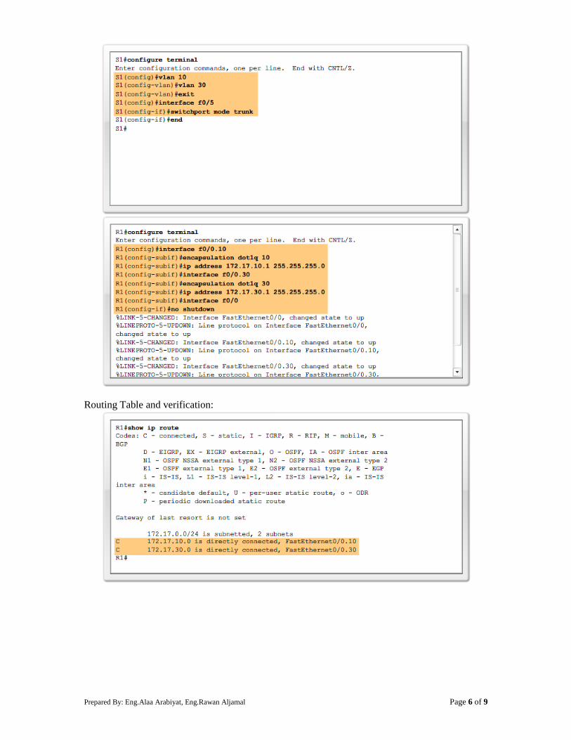
Prepared By: Eng.Alaa Arabiyat, Eng.Rawan Aljamal Page 6 of 9
Routing Table and verification:
Prepared By: Eng.Alaa Arabiyat, Eng.Rawan Aljamal Page 7 of 9
Configure inter-VLAN routing using Layer 3 switching
Configure the VLAN interfaces with the IP address
Switch#configure terminal
Enter configuration commands, one per line. End with CNTL/Z.
Switch(config)#interface Vlan10
Switch(config-if)#ip address 192.168.10.1 255.255.255.0
Switch(config-if)#no shutdown
Repeat this process for all VLANs
Configure the access interfaces with the associated VLAN
Switch(config)#interface fastEthernet 0/10
Switch(config-if)#switchport mode access
Switch(config-if)#switchport access vlan 10
Switch(config-if)#exit
Repeat this process for all switch ports
3. Inter-VLAN Configuration Issues
There are several common switch misconfigurations that can arise when configuring routing
between multiple VLANs.
When using the traditional routing model for inter-VLAN routing, ensure that the switch ports
that connect to the router interfaces are configured with the correct VLANs. If a switch port is not
configured for the correct VLAN, devices configured on that VLAN cannot connect to the router
interface; therefore, those devices are unable to send data to the other VLANs.
As shown in the Figure topology below, PC1 and router R1 interface G0/0 are configured to be
on the same logical subnet, as indicated by their IP address assignment. However, the switch port
F0/4 that connects to router R1 interface G0/0 has not been configured and remains in the default
VLAN. Because router R1 is on a different VLAN than PC1, they are unable to communicate. To
correct this problem, execute the switchport access vlan 10 interface configuration mode
command on switch port F0/4 on switch S1. When the switch port is configured for the correct
VLAN, PC1 can communicate with router R1 interface G0/0, which allows it to access the other
VLANs connected to router R1.
Prepared By: Eng.Alaa Arabiyat, Eng.Rawan Aljamal Page 8 of 9
The following Figure topology shows the router-on-a-stick routing model. However,
interface F0/5 on switch S1 is not configured as a trunk and is left in the default VLAN for the
port. As a result, the router is unable to route between VLANs because each of its configured
subinterfaces is unable to send or receive VLAN-tagged traffic.
To correct this problem, issue the switchport mode trunk interface configuration mode
command on switch port F0/5 on S1. This converts the interface to a trunk port, allowing a trunk
to be established between R1 and S1. When the trunk is successfully established, devices
connected to each of the VLANs are able to communicate with the subinterface assigned to their
VLAN, thus enabling inter-VLAN routing.
The Figure topology below shows the trunk link between S1 and S2 is down. Because there is no
redundant connection or path between the devices, all devices connected to S2 are unable to reach
router R1. As a result, all devices connected to S2 are unable to route to other VLANs through
R1. To reduce the risk of a failed inter-switch link disrupting inter-VLAN routing, redundant
links and alternate paths should be accounted for within the network design.
Prepared By: Eng.Alaa Arabiyat, Eng.Rawan Aljamal Page 9 of 9
With router-on-a-stick configurations, a common problem is assigning the wrong VLAN ID to
the subinterface as shown in the Figure below. Router R1 has been configured with the
wrong VLAN on subinterface G0/0.10, preventing devices configured on VLAN 10 from
communicating with subinterface G0/0.10. This subsequently prevents those devices
from being able to send data to other VLANs on the network. Using the show interface
and the show running-config commands can be useful in troubleshooting this issue.
To correct this problem, configure subinterface G0/0.10 to be on the correct VLAN using the
encapsulation dot1q 10 subinterface configuration mode command. When the subinterface has
been assigned to the correct VLAN, it is accessible by devices on that VLAN and the router can
perform inter-VLAN routing. With proper verification, router configuration problems are quickly
addressed, allowing inter-VLAN routing to function properly.
Procedure:
You can find the lab problem sheet and the packet tracer activities on the lab website.
Reference:
CCNA Routing and Switching - Cisco Networking Academy.
Prepared By: Eng.Alaa Arabiyat, Eng.Rawan Aljamal Page 1 of 10
University of Jordan
Faculty of Engineering & Technology
Computer Engineering Department
Advance Networks Laboratory 0907529
Exp.5 Spanning-Tree Protocol (STP)
Objectives
1. Explain the role of redundancy in a converged network.
2. Summarize how STP works to eliminate Layer 2 loops in a converged network.
3. Explain how the STP algorithm uses three steps to converge on a loop-free topology.
1. Introduction:
It is clear that computer networks are critical components of most small- and medium-sized
businesses. Consequently IT administrators have to implement redundancy in their hierarchical
networks. However adding extra links to switches and routers in the network introduces traffic
loops that need to be managed in a dynamic way; when a switch connection is lost, another link
needs to quickly take its place without introducing new traffic loops. In this experiment you will
learn how spanning-tree protocol (STP) prevents loop issues in the network and how STP has
evolved into a protocol that rapidly calculates which ports should be blocked so that a VLAN-
based network is kept free of traffic loops.
Redundancy in a hierarchical network
The hierarchical design model addresses issues found in the flat model network topologies. One
of the issues is redundancy. Layer 2 redundancy improves the availability of the network by
implementing alternate network paths by adding equipment and cabling. Having multiple paths
for data to traverse the network allows for a single path to be disrupted without impacting the
connectivity of devices on the network. As you can see in the figure below:
1. PC1 is communicating with PC4 over a redundantly configured network topology.
2. When the network link between switch S1 and switch S2 is disrupted, the path between PC1
and PC4 is automatically adjusted to compensate for the disruption.
3. When the network connection between S1 and S2 is restored, the path is then readjusted to
route traffic directly from S2 through S1 to get to PC4.
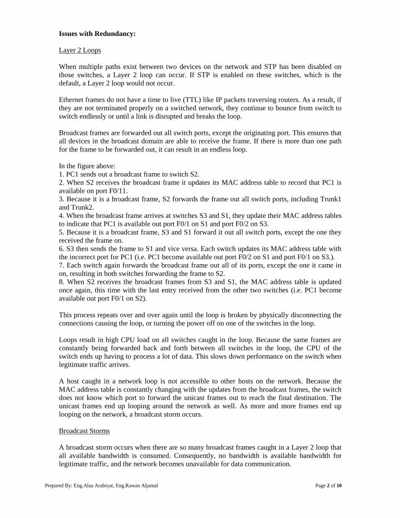
Prepared By: Eng.Alaa Arabiyat, Eng.Rawan Aljamal Page 2 of 10
Issues with Redundancy:
Layer 2 Loops
When multiple paths exist between two devices on the network and STP has been disabled on
those switches, a Layer 2 loop can occur. If STP is enabled on these switches, which is the
default, a Layer 2 loop would not occur.
Ethernet frames do not have a time to live (TTL) like IP packets traversing routers. As a result, if
they are not terminated properly on a switched network, they continue to bounce from switch to
switch endlessly or until a link is disrupted and breaks the loop.
Broadcast frames are forwarded out all switch ports, except the originating port. This ensures that
all devices in the broadcast domain are able to receive the frame. If there is more than one path
for the frame to be forwarded out, it can result in an endless loop.
In the figure above:
1. PC1 sends out a broadcast frame to switch S2.
2. When S2 receives the broadcast frame it updates its MAC address table to record that PC1 is
available on port F0/11.
3. Because it is a broadcast frame, S2 forwards the frame out all switch ports, including Trunk1
and Trunk2.
4. When the broadcast frame arrives at switches S3 and S1, they update their MAC address tables
to indicate that PC1 is available out port F0/1 on S1 and port F0/2 on S3.
5. Because it is a broadcast frame, S3 and S1 forward it out all switch ports, except the one they
received the frame on.
6. S3 then sends the frame to S1 and vice versa. Each switch updates its MAC address table with
the incorrect port for PC1 (i.e. PC1 become available out port F0/2 on S1 and port F0/1 on S3.).
7. Each switch again forwards the broadcast frame out all of its ports, except the one it came in
on, resulting in both switches forwarding the frame to S2.
8. When S2 receives the broadcast frames from S3 and S1, the MAC address table is updated
once again, this time with the last entry received from the other two switches (i.e. PC1 become
available out port F0/1 on S2).
This process repeats over and over again until the loop is broken by physically disconnecting the
connections causing the loop, or turning the power off on one of the switches in the loop.
Loops result in high CPU load on all switches caught in the loop. Because the same frames are
constantly being forwarded back and forth between all switches in the loop, the CPU of the
switch ends up having to process a lot of data. This slows down performance on the switch when
legitimate traffic arrives.
A host caught in a network loop is not accessible to other hosts on the network. Because the
MAC address table is constantly changing with the updates from the broadcast frames, the switch
does not know which port to forward the unicast frames out to reach the final destination. The
unicast frames end up looping around the network as well. As more and more frames end up
looping on the network, a broadcast storm occurs.
Broadcast Storms
A broadcast storm occurs when there are so many broadcast frames caught in a Layer 2 loop that
all available bandwidth is consumed. Consequently, no bandwidth is available bandwidth for
legitimate traffic, and the network becomes unavailable for data communication.
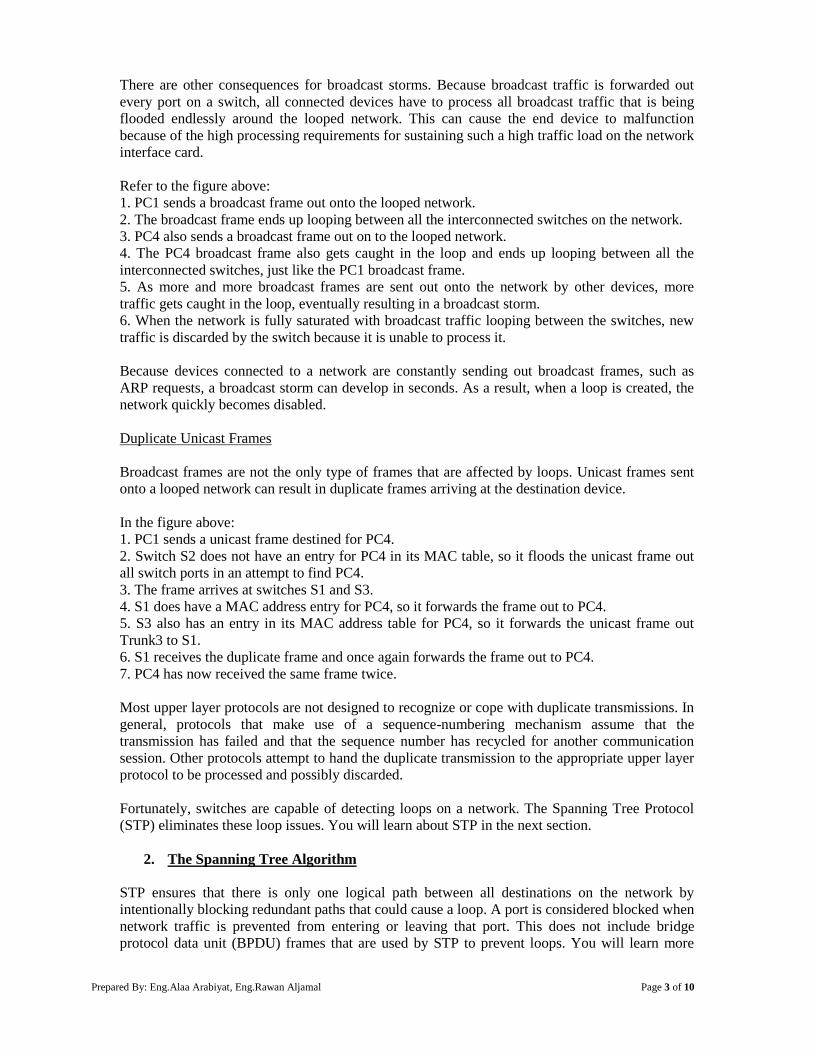
Prepared By: Eng.Alaa Arabiyat, Eng.Rawan Aljamal Page 3 of 10
There are other consequences for broadcast storms. Because broadcast traffic is forwarded out
every port on a switch, all connected devices have to process all broadcast traffic that is being
flooded endlessly around the looped network. This can cause the end device to malfunction
because of the high processing requirements for sustaining such a high traffic load on the network
interface card.
Refer to the figure above:
1. PC1 sends a broadcast frame out onto the looped network.
2. The broadcast frame ends up looping between all the interconnected switches on the network.
3. PC4 also sends a broadcast frame out on to the looped network.
4. The PC4 broadcast frame also gets caught in the loop and ends up looping between all the
interconnected switches, just like the PC1 broadcast frame.
5. As more and more broadcast frames are sent out onto the network by other devices, more
traffic gets caught in the loop, eventually resulting in a broadcast storm.
6. When the network is fully saturated with broadcast traffic looping between the switches, new
traffic is discarded by the switch because it is unable to process it.
Because devices connected to a network are constantly sending out broadcast frames, such as
ARP requests, a broadcast storm can develop in seconds. As a result, when a loop is created, the
network quickly becomes disabled.
Duplicate Unicast Frames
Broadcast frames are not the only type of frames that are affected by loops. Unicast frames sent
onto a looped network can result in duplicate frames arriving at the destination device.
In the figure above:
1. PC1 sends a unicast frame destined for PC4.
2. Switch S2 does not have an entry for PC4 in its MAC table, so it floods the unicast frame out
all switch ports in an attempt to find PC4.
3. The frame arrives at switches S1 and S3.
4. S1 does have a MAC address entry for PC4, so it forwards the frame out to PC4.
5. S3 also has an entry in its MAC address table for PC4, so it forwards the unicast frame out
Trunk3 to S1.
6. S1 receives the duplicate frame and once again forwards the frame out to PC4.
7. PC4 has now received the same frame twice.
Most upper layer protocols are not designed to recognize or cope with duplicate transmissions. In
general, protocols that make use of a sequence-numbering mechanism assume that the
transmission has failed and that the sequence number has recycled for another communication
session. Other protocols attempt to hand the duplicate transmission to the appropriate upper layer
protocol to be processed and possibly discarded.
Fortunately, switches are capable of detecting loops on a network. The Spanning Tree Protocol
(STP) eliminates these loop issues. You will learn about STP in the next section.
2. The Spanning Tree Algorithm
STP ensures that there is only one logical path between all destinations on the network by
intentionally blocking redundant paths that could cause a loop. A port is considered blocked when
network traffic is prevented from entering or leaving that port. This does not include bridge
protocol data unit (BPDU) frames that are used by STP to prevent loops. You will learn more
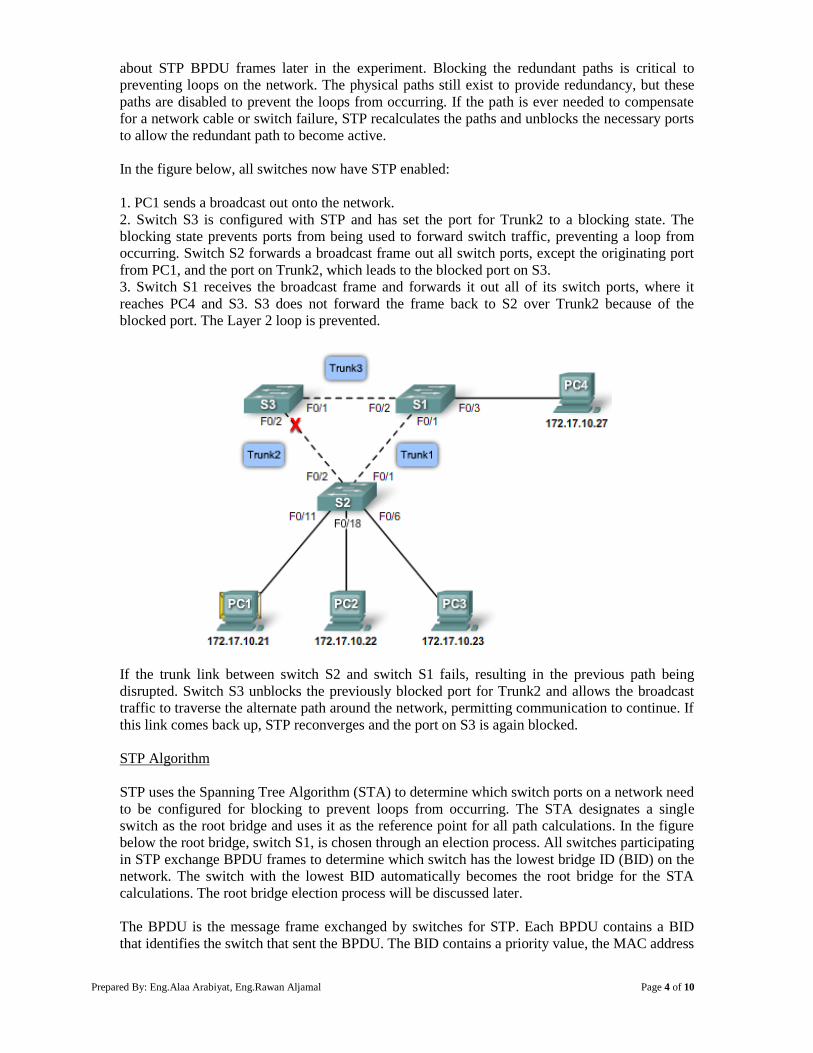
Prepared By: Eng.Alaa Arabiyat, Eng.Rawan Aljamal Page 4 of 10
about STP BPDU frames later in the experiment. Blocking the redundant paths is critical to
preventing loops on the network. The physical paths still exist to provide redundancy, but these
paths are disabled to prevent the loops from occurring. If the path is ever needed to compensate
for a network cable or switch failure, STP recalculates the paths and unblocks the necessary ports
to allow the redundant path to become active.
In the figure below, all switches now have STP enabled:
1. PC1 sends a broadcast out onto the network.
2. Switch S3 is configured with STP and has set the port for Trunk2 to a blocking state. The
blocking state prevents ports from being used to forward switch traffic, preventing a loop from
occurring. Switch S2 forwards a broadcast frame out all switch ports, except the originating port
from PC1, and the port on Trunk2, which leads to the blocked port on S3.
3. Switch S1 receives the broadcast frame and forwards it out all of its switch ports, where it
reaches PC4 and S3. S3 does not forward the frame back to S2 over Trunk2 because of the
blocked port. The Layer 2 loop is prevented.
If the trunk link between switch S2 and switch S1 fails, resulting in the previous path being
disrupted. Switch S3 unblocks the previously blocked port for Trunk2 and allows the broadcast
traffic to traverse the alternate path around the network, permitting communication to continue. If
this link comes back up, STP reconverges and the port on S3 is again blocked.
STP Algorithm
STP uses the Spanning Tree Algorithm (STA) to determine which switch ports on a network need
to be configured for blocking to prevent loops from occurring. The STA designates a single
switch as the root bridge and uses it as the reference point for all path calculations. In the figure
below the root bridge, switch S1, is chosen through an election process. All switches participating
in STP exchange BPDU frames to determine which switch has the lowest bridge ID (BID) on the
network. The switch with the lowest BID automatically becomes the root bridge for the STA
calculations. The root bridge election process will be discussed later.
The BPDU is the message frame exchanged by switches for STP. Each BPDU contains a BID
that identifies the switch that sent the BPDU. The BID contains a priority value, the MAC address
Prepared By: Eng.Alaa Arabiyat, Eng.Rawan Aljamal Page 5 of 10
of the sending switch, and an optional extended system ID. The lowest BID value is determined
by the combination of these three fields.
After the root bridge has been determined, the STA calculates the shortest path to the root bridge.
Each switch uses the STA to determine which ports to block. While the STA determines the best
paths to the root bridge for all destinations in the broadcast domain, all traffic is prevented from
forwarding through the network. The STA considers both path and port costs when determining
which path to leave unblocked. The path costs are calculated using port cost values associated
with port speeds for each switch port along a given path. The sum of the port cost values
determines the overall path cost to the root bridge. If there is more than one path to choose from,
STA chooses the path with the lowest path cost.
When the STA has determined which paths are to be left available, it configures the switch ports
into distinct port roles. The port roles describe their relation in the network to the root bridge and
whether they are allowed to forward traffic.
Port Roles
The root bridge is elected for the spanning-tree instance. The location of the root bridge in the
network topology determines how port roles are calculated. This topic describes how the switch
ports are configured for specific roles to prevent the possibility of loops on the network.
There are four distinct port roles that switch ports are automatically configured for during the
spanning-tree process.
Root Port
The root port exists on non-root bridges and is the switch port with the best path to the root
bridge. Root ports forward traffic toward the root bridge. One root port is allowed per bridge.
In the example below, switch S1 is the root bridge and switches S2 and S3 have root ports
defined on the trunk links connecting back to S1.
Designated Port
The designated port exists on root and non-root bridges. For root bridges, all switch ports are
designated ports. For non-root bridges, a designated port is the switch port that receives and
forwards frames toward the root bridge as needed. Only one designated port is allowed per
segment. If multiple switches exist on the same segment, an election process determines the
designated switch, and the corresponding switch port begins forwarding frames for the segment.
Designated ports are capable of populating the MAC table.
In the example below, switch S1 has both sets of ports for its two trunk links configured as
designated ports. Switch S2 also has a designated port configured on the trunk link going toward
switch S3.
Non-designated Port
The non-designated port is a switch port that is blocked, so it is not forwarding data frames and
not populating the MAC address table with source addresses. A non-designated port is not a root
port or a designated port. For some variants of STP, the non-designated port is called an alternate
port.
In the example below, switch S3 has the only non-designated ports in the topology. The non-
designated ports prevent the loop from occurring.
Disabled Port
The disabled port is a switch port that is administratively shut down. A disabled port does not
function in the spanning-tree process. There are no disabled ports in the example.
Prepared By: Eng.Alaa Arabiyat, Eng.Rawan Aljamal Page 6 of 10
The Root Bridge
Every spanning-tree instance (switched LAN or broadcast domain) has a switch designated as the
root bridge. The root bridge serves as a reference point for all spanning-tree calculations to
determine which redundant paths to block.
An election process determines which switch becomes the root bridge. The figure below shows
the BID fields. The BID is made up of a priority value, an extended system ID, and the MAC
address of the switch.
All switches in the broadcast domain participate in the election process. After a switch boots, it
sends out BPDU frames containing the switch BID and the root ID every 2 seconds. By default,
the root ID matches the local BID for all switches on the network. The root ID identifies the root
bridge on the network. Initially, each switch identifies itself as the root bridge after bootup.
As the switches forward their BPDU frames, adjacent switches in the broadcast domain read the
root ID information from the BPDU frame. If the root ID from the BPDU received is lower than
the root ID on the receiving switch, the receiving switch updates its root ID identifying the
adjacent switch as the root bridge. Note: It may not be an adjacent switch, but any other switch in
the broadcast domain. The switch then forwards new BPDU frames with the lower root ID to the
other adjacent switches. Eventually, the switch with the lowest BID ends up being identified as
the root bridge for the spanning-tree instance.
Prepared By: Eng.Alaa Arabiyat, Eng.Rawan Aljamal Page 7 of 10
Best Paths to the Root Bridge
When the root bridge has been designated for the spanning-tree instance, the STA starts the
process of determining the best paths to the root bridge from all destinations in the broadcast
domain. The path information is determined by summing up the individual port costs along the
path from the destination to the root bridge.
The default port costs are defined by the speed at which the port operates, 10-Gb/s Ethernet ports
have a port cost of 2, 1-Gb/s Ethernet ports have a port cost of 4, 100-Mb/s Fast Ethernet ports
have a port cost of 19, and 10-Mb/s Ethernet ports have a port cost of 100.
Although switch ports have a default port cost associated with them, the port cost is configurable
as shown in the figure below. The ability to configure individual port costs gives the
administrator the flexibility to control the spanning-tree paths to the root bridge.
Path cost is the sum of all the port costs along the path to the root bridge. The paths with the
lowest path cost become the preferred path, and all other redundant paths are blocked. In the
example, the path cost from switch S2 to the root bridge switch S1, over path 1 is 19 (based on
the IEEE-specified individual port cost), while the path cost over path 2 is 38. Because path 1 has
a lower overall path cost to the root bridge, it is the preferred path. STP then configures the
redundant path to be blocked, preventing a loop from occurring.
To verify the port and path cost to the root bridge, enter the show spanning-tree privileged EXEC
mode command. The Cost field in the output is the total path cost to the root bridge. This value
changes depending on how many switch ports need to be traversed to get to the root bridge. In the
output, each interface is also identified with an individual port cost of 19.
Prepared By: Eng.Alaa Arabiyat, Eng.Rawan Aljamal Page 8 of 10
Configure and Verify the BID
When a specific switch is to become a root bridge, the bridge priority value needs to be adjusted
to ensure it is lower than the bridge priority values of all the other switches on the network. There
are two different configuration methods that you can use to configure the bridge priority value on
a Cisco Catalyst switch.
Method 1 - To ensure that the switch has the lowest bridge priority value, use the spanning-tree
vlan vlan-id root primary command in global configuration mode. The priority for the switch is
set to the predefined value of 24576 or to the next 4096 increment value below the lowest bridge
priority detected on the network.
If an alternate root bridge is desired, use the spanning-tree vlan vlan-id root secondary global
configuration mode command. This command sets the priority for the switch to the predefined
value of 28672. This ensures that this switch becomes the root bridge if the primary root bridge
fails and a new root bridge election occurs and assuming that the rest of the switches in the
network have the default 32768 priority value defined.
In the example below, switch S1 has been assigned as the primary root bridge using the spanning-
tree vlan 1 root primary global configuration mode command, and switch S2 has been configured
as the secondary root bridge using the spanning-tree vlan 1 root secondary global configuration
mode command.
Method 2 - Another method for configuring the bridge priority value is using the spanning-tree
vlan vlan-id priority value global configuration mode command. This command gives you more
granular control over the bridge priority value. The priority value is configured in increments of
4096 between 0 and 65536.
In the example below, switch S3 has been assigned a bridge priority value of 24576 using the
spanning-tree vlan 1 priority 24576 global configuration mode command.
To verify the bridge priority of a switch, use the show spanning-tree privileged EXEC mode
command. In the example, the priority of the switch has been set to 24576. Also notice that the
switch is designated as the root bridge for the spanning-tree instance.
Prepared By: Eng.Alaa Arabiyat, Eng.Rawan Aljamal Page 9 of 10
Port States
STP determines the logical loop-free path throughout the broadcast domain. The spanning tree is
determined through the information learned by the exchange of the BPDU frames between the
interconnected switches. To facilitate the learning of the logical spanning tree, each switch port
transitions through five possible port states and three BPDU timers.
The spanning tree is determined immediately after a switch is finished booting up. If a switch port
were to transition directly from the blocking to the forwarding state, the port could temporarily
create a data loop if the switch was not aware of all topology information at the time. For this
reason, STP introduces five port states. The table below summarizes what each port state does.
The following provides some additional information on how the port states ensure that no loops
are created during the creation of the logical spanning tree.
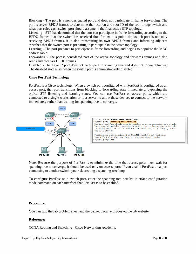
Prepared By: Eng.Alaa Arabiyat, Eng.Rawan Aljamal Page 10 of 10
Blocking - The port is a non-designated port and does not participate in frame forwarding. The
port receives BPDU frames to determine the location and root ID of the root bridge switch and
what port roles each switch port should assume in the final active STP topology.
Listening - STP has determined that the port can participate in frame forwarding according to the
BPDU frames that the switch has received thus far. At this point, the switch port is not only
receiving BPDU frames, it is also transmitting its own BPDU frames and informing adjacent
switches that the switch port is preparing to participate in the active topology.
Learning - The port prepares to participate in frame forwarding and begins to populate the MAC
address table.
Forwarding - The port is considered part of the active topology and forwards frames and also
sends and receives BPDU frames.
Disabled - The Layer 2 port does not participate in spanning tree and does not forward frames.
The disabled state is set when the switch port is administratively disabled.
Cisco PortFast Technology
PortFast is a Cisco technology. When a switch port configured with PortFast is configured as an
access port, that port transitions from blocking to forwarding state immediately, bypassing the
typical STP listening and learning states. You can use PortFast on access ports, which are
connected to a single workstation or to a server, to allow those devices to connect to the network
immediately rather than waiting for spanning tree to converge.
Note: Because the purpose of PortFast is to minimize the time that access ports must wait for
spanning tree to converge, it should be used only on access ports. If you enable PortFast on a port
connecting to another switch, you risk creating a spanning-tree loop.
To configure PortFast on a switch port, enter the spanning-tree portfast interface configuration
mode command on each interface that PortFast is to be enabled.
Procedure:
You can find the lab problem sheet and the packet tracer activities on the lab website.
Reference:
CCNA Routing and Switching - Cisco Networking Academy.
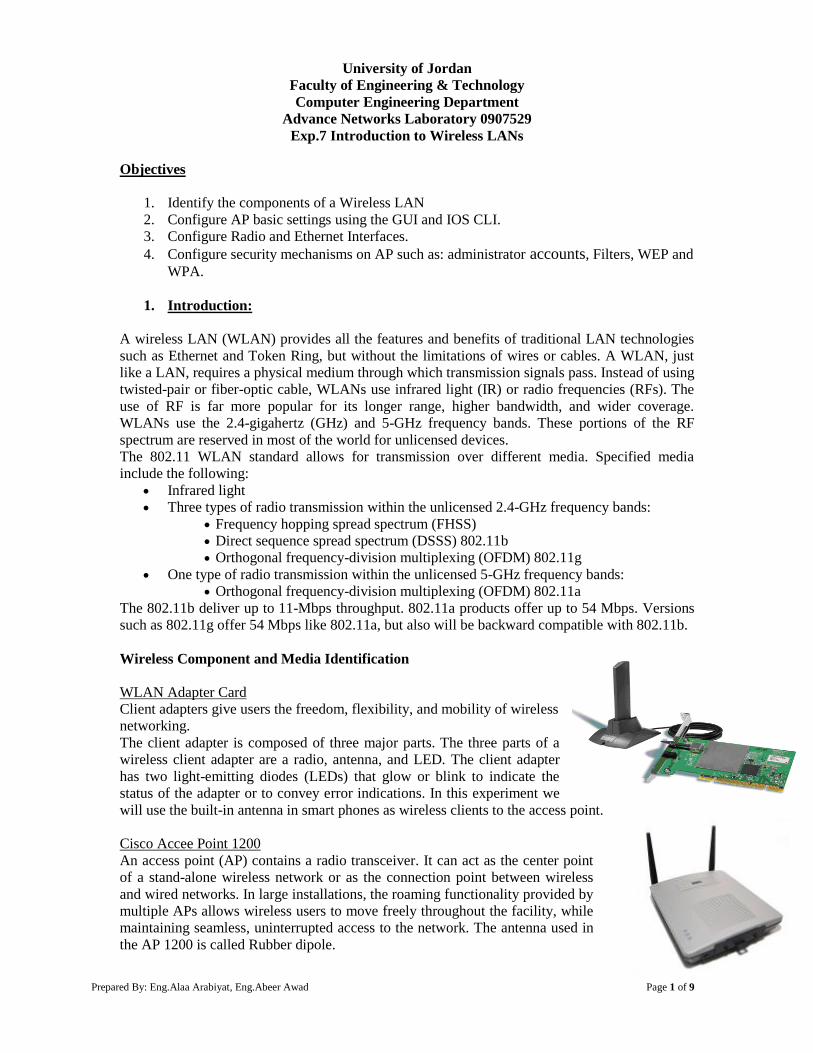
Prepared By: Eng.Alaa Arabiyat, Eng.Abeer Awad Page 1 of 9
University of Jordan
Faculty of Engineering & Technology
Computer Engineering Department
Advance Networks Laboratory 0907529
Exp.7 Introduction to Wireless LANs
Objectives
1. Identify the components of a Wireless LAN
2. Configure AP basic settings using the GUI and IOS CLI.
3. Configure Radio and Ethernet Interfaces.
4. Configure security mechanisms on AP such as: administrator accounts, Filters, WEP and
WPA.
1. Introduction:
A wireless LAN (WLAN) provides all the features and benefits of traditional LAN technologies
such as Ethernet and Token Ring, but without the limitations of wires or cables. A WLAN, just
like a LAN, requires a physical medium through which transmission signals pass. Instead of using
twisted-pair or fiber-optic cable, WLANs use infrared light (IR) or radio frequencies (RFs). The
use of RF is far more popular for its longer range, higher bandwidth, and wider coverage.
WLANs use the 2.4-gigahertz (GHz) and 5-GHz frequency bands. These portions of the RF
spectrum are reserved in most of the world for unlicensed devices.
The 802.11 WLAN standard allows for transmission over different media. Specified media
include the following:
Infrared light
Three types of radio transmission within the unlicensed 2.4-GHz frequency bands:
Frequency hopping spread spectrum (FHSS)
Direct sequence spread spectrum (DSSS) 802.11b
Orthogonal frequency-division multiplexing (OFDM) 802.11g
One type of radio transmission within the unlicensed 5-GHz frequency bands:
Orthogonal frequency-division multiplexing (OFDM) 802.11a
The 802.11b deliver up to 11-Mbps throughput. 802.11a products offer up to 54 Mbps. Versions
such as 802.11g offer 54 Mbps like 802.11a, but also will be backward compatible with 802.11b.
Wireless Component and Media Identification
WLAN Adapter Card
Client adapters give users the freedom, flexibility, and mobility of wireless
networking.
The client adapter is composed of three major parts. The three parts of a
wireless client adapter are a radio, antenna, and LED. The client adapter
has two light-emitting diodes (LEDs) that glow or blink to indicate the
status of the adapter or to convey error indications. In this experiment we
will use the built-in antenna in smart phones as wireless clients to the access point.
Cisco Accee Point 1200
An access point (AP) contains a radio transceiver. It can act as the center point
of a stand-alone wireless network or as the connection point between wireless
and wired networks. In large installations, the roaming functionality provided by
multiple APs allows wireless users to move freely throughout the facility, while
maintaining seamless, uninterrupted access to the network. The antenna used in
the AP 1200 is called Rubber dipole.
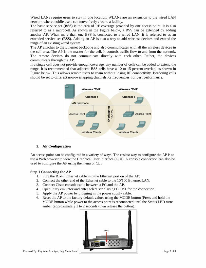
Prepared By: Eng.Alaa Arabiyat, Eng.Abeer Awad Page 2 of 9
Wired LANs require users to stay in one location. WLANs are an extension to the wired LAN
network where mobile users can move freely around a facility.
The basic service set (BSS) is the area of RF coverage provided by one access point. It is also
referred to as a microcell. As shown in the Figure below, a BSS can be extended by adding
another AP. When more than one BSS is connected to a wired LAN, it is referred to as an
extended service set (ESS). Adding an AP is also a way to add wireless devices and extend the
range of an existing wired system.
The AP attaches to the Ethernet backbone and also communicates with all the wireless devices in
the cell area. The AP is the master for the cell. It controls traffic flow to and from the network.
The remote devices do not communicate directly with each other. Rather, the devices
communicate through the AP.
If a single cell does not provide enough coverage, any number of cells can be added to extend the
range. It is recommended that adjacent BSS cells have a 10 to 15 percent overlap, as shown in
Figure below. This allows remote users to roam without losing RF connectivity. Bordering cells
should be set to different non-overlapping channels, or frequencies, for best performance.
2. AP Configuration
An access point can be configured in a variety of ways. The easiest way to configure the AP is to
use a Web browser to view the Graphical User Interface (GUI). A console connection can also be
used to configure the AP using the menu or CLI.
Step 1 Connecting the AP 1. Plug the RJ-45 Ethernet cable into the Ethernet port on of the AP.
2. Connect the other end of the Ethernet cable to the 10/100 Ethernet LAN.
3. Connect Cisco console cable between a PC and the AP.
4. Open Putty emulator and enter select serial using COM1 for the connection.
5. Apply the AP power by plugging in the power supply cable.
6. Reset the AP to the factory default values using the MODE button (Press and hold the
MODE button while power to the access point is reconnected until the Status LED turns
amber (approximately 1 to 2 seconds) then release the button).
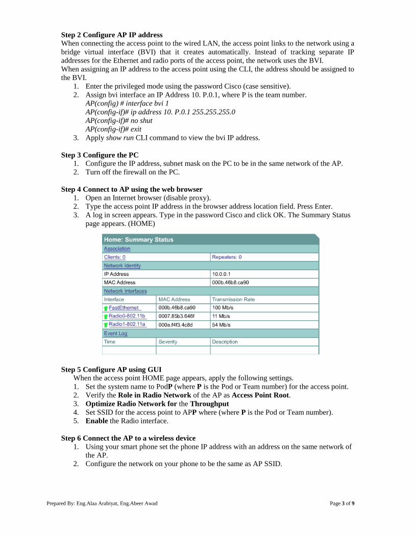
Prepared By: Eng.Alaa Arabiyat, Eng.Abeer Awad Page 3 of 9
Step 2 Configure AP IP address
When connecting the access point to the wired LAN, the access point links to the network using a
bridge virtual interface (BVI) that it creates automatically. Instead of tracking separate IP
addresses for the Ethernet and radio ports of the access point, the network uses the BVI.
When assigning an IP address to the access point using the CLI, the address should be assigned to
the BVI.
1. Enter the privileged mode using the password Cisco (case sensitive).
2. Assign bvi interface an IP Address 10. P.0.1, where P is the team number.
AP(config) # interface bvi 1
AP(config-if)# ip address 10. P.0.1 255.255.255.0
AP(config-if)# no shut
AP(config-if)# exit
3. Apply show run CLI command to view the bvi IP address.
Step 3 Configure the PC
1. Configure the IP address, subnet mask on the PC to be in the same network of the AP.
2. Turn off the firewall on the PC.
Step 4 Connect to AP using the web browser
1. Open an Internet browser (disable proxy).
2. Type the access point IP address in the browser address location field. Press Enter.
3. A log in screen appears. Type in the password Cisco and click OK. The Summary Status
page appears. (HOME)
Step 5 Configure AP using GUI
When the access point HOME page appears, apply the following settings.
1. Set the system name to PodP (where P is the Pod or Team number) for the access point.
2. Verify the Role in Radio Network of the AP as Access Point Root.
3. Optimize Radio Network for the Throughput
4. Set SSID for the access point to APP where (where P is the Pod or Team number).
5. Enable the Radio interface.
Step 6 Connect the AP to a wireless device
1. Using your smart phone set the phone IP address with an address on the same network of
the AP.
2. Configure the network on your phone to be the same as AP SSID.
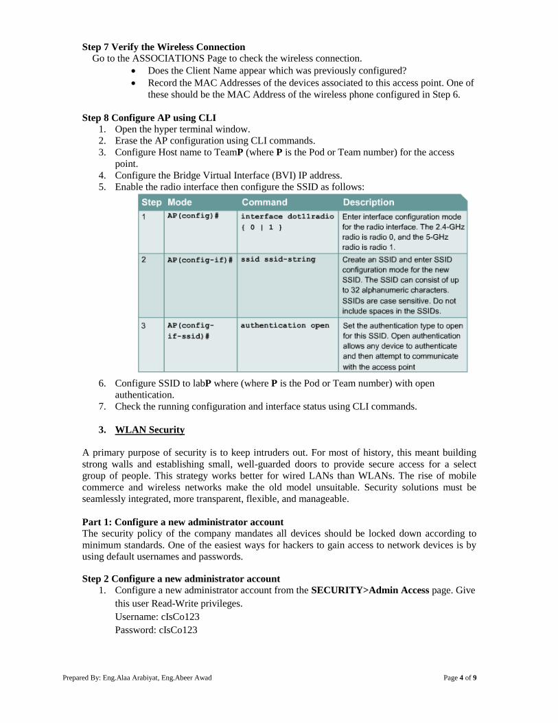
Prepared By: Eng.Alaa Arabiyat, Eng.Abeer Awad Page 4 of 9
Step 7 Verify the Wireless Connection
Go to the ASSOCIATIONS Page to check the wireless connection.
Does the Client Name appear which was previously configured?
Record the MAC Addresses of the devices associated to this access point. One of
these should be the MAC Address of the wireless phone configured in Step 6.
Step 8 Configure AP using CLI
1. Open the hyper terminal window.
2. Erase the AP configuration using CLI commands.
3. Configure Host name to TeamP (where P is the Pod or Team number) for the access
point.
4. Configure the Bridge Virtual Interface (BVI) IP address.
5. Enable the radio interface then configure the SSID as follows:
6. Configure SSID to labP where (where P is the Pod or Team number) with open
authentication.
7. Check the running configuration and interface status using CLI commands.
3. WLAN Security
A primary purpose of security is to keep intruders out. For most of history, this meant building
strong walls and establishing small, well-guarded doors to provide secure access for a select
group of people. This strategy works better for wired LANs than WLANs. The rise of mobile
commerce and wireless networks make the old model unsuitable. Security solutions must be
seamlessly integrated, more transparent, flexible, and manageable.
Part 1: Configure a new administrator account
The security policy of the company mandates all devices should be locked down according to
minimum standards. One of the easiest ways for hackers to gain access to network devices is by
using default usernames and passwords.
Step 2 Configure a new administrator account
1. Configure a new administrator account from the SECURITY>Admin Access page. Give
this user Read-Write privileges.
Username: cIsCo123
Password: cIsCo123
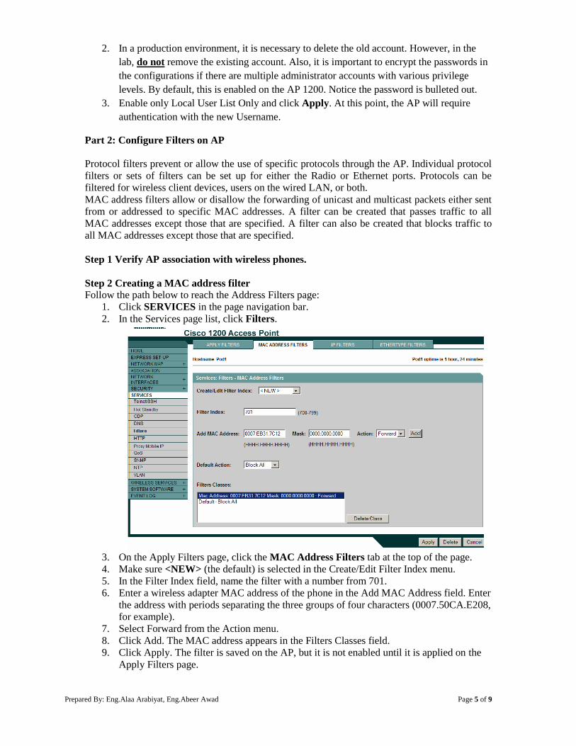
Prepared By: Eng.Alaa Arabiyat, Eng.Abeer Awad Page 5 of 9
2. In a production environment, it is necessary to delete the old account. However, in the
lab, do not remove the existing account. Also, it is important to encrypt the passwords in
the configurations if there are multiple administrator accounts with various privilege
levels. By default, this is enabled on the AP 1200. Notice the password is bulleted out.
3. Enable only Local User List Only and click Apply. At this point, the AP will require
authentication with the new Username.
Part 2: Configure Filters on AP
Protocol filters prevent or allow the use of specific protocols through the AP. Individual protocol
filters or sets of filters can be set up for either the Radio or Ethernet ports. Protocols can be
filtered for wireless client devices, users on the wired LAN, or both.
MAC address filters allow or disallow the forwarding of unicast and multicast packets either sent
from or addressed to specific MAC addresses. A filter can be created that passes traffic to all
MAC addresses except those that are specified. A filter can also be created that blocks traffic to
all MAC addresses except those that are specified.
Step 1 Verify AP association with wireless phones.
Step 2 Creating a MAC address filter
Follow the path below to reach the Address Filters page:
1. Click SERVICES in the page navigation bar.
2. In the Services page list, click Filters.
3. On the Apply Filters page, click the MAC Address Filters tab at the top of the page.
4. Make sure <NEW> (the default) is selected in the Create/Edit Filter Index menu.
5. In the Filter Index field, name the filter with a number from 701.
6. Enter a wireless adapter MAC address of the phone in the Add MAC Address field. Enter
the address with periods separating the three groups of four characters (0007.50CA.E208,
for example).
7. Select Forward from the Action menu.
8. Click Add. The MAC address appears in the Filters Classes field.
9. Click Apply. The filter is saved on the AP, but it is not enabled until it is applied on the
Apply Filters page.
Prepared By: Eng.Alaa Arabiyat, Eng.Abeer Awad Page 6 of 9
Step 3 Apply the MAC address filter
1. From the SERVICES>Filters Page, go to the APPLY FILTERS tab.
2. Select the filter number 701 from the Radio0-802.11B MAC drop-down menus. Apply
the filter to incoming and outgoing packets.
3. Click Apply. The filter is enabled on the selected ports.
Note Client devices with blocked MAC addresses cannot send or receive data through the
AP, but they might remain in the Association Table as unauthenticated client devices.
Client devices with blocked MAC addresses disappear from the Association Table when
the AP stops monitoring them, when the AP reboots, or when the clients associate with
another AP.
Step 5 Remove the MAC address filter
Before configuring any IP Filters, delete the existing MAC filter.
1. From the SERVICES>Filters Page change the 701 to <NONE> on both Incoming and
outgoing. Then click Apply.
Step 6 Creating an IP filter
Follow this link path to reach the IP Filters page:
1. Click Services in the page navigation bar.
2. In the Services page list, click Filters.
3. On the Apply Filters page, click the IP Filters tab at the top of the page.
4. Make sure <NEW> (the default) is selected in the Create/Edit Filter Index menu, and
then click the Add button.
5. Enter a descriptive name of MYFILTER for the new filter in the Filter Name field.
6. Select Block all as the filter's default action from the Default Action menu.
7. Configure the Destination Address: of 0.0.0.0 and a Mask: of 255.255.255.255.
8. Add the IP address of PC2 as the Source Address: with a Mask: of 0.0.0.0 to permit
PC2 traffic.
9. Make sure Forward is selected for the Action:
10. Click the Add button. The ACL will now appear in the Filters Classes Box at the bottom
of the Filters page.
11. Verify the configuration in the Filters Classes box.
12. If the configuration is correct, click Apply
Step 7 Apply the IP filter
1. Select MYFILTER from the radio ports incoming and outgoing IP fields.
2. Click Apply. The filter is now enabled on the selected interface(s).
Part 3: Configure WEP on AP and Client
Wired Equivalent Privacy (WEP) is a security protocol for wireless networks that encrypts
transmitted data. It's easy to configure. Without any security your data can be intercepted without
difficulty. However, WEP was an early attempt to secure wireless networks, and better security is
now available such as DES, 3DES, and WPA.
WEP has three settings: Off (no security), 40-bit (weak security), 128-bit (a bit better security).
WEP is not difficult to crack, and using it reduces performance slightly.
If you run a network with only the default security, where WEP is turned off, any of your
neighbors can immediately log on to your network and use your Internet connection.
For wireless devices to communicate, all of them must use the same WEP setting. 128-bit
security is not much more difficult than 40-bit to crack, so if you are concerned about
performance, consider using 40-bit. If you're very concerned about security, use WPA, which
replaces WEP with a protocol that is — given current technology — impossible to crack.
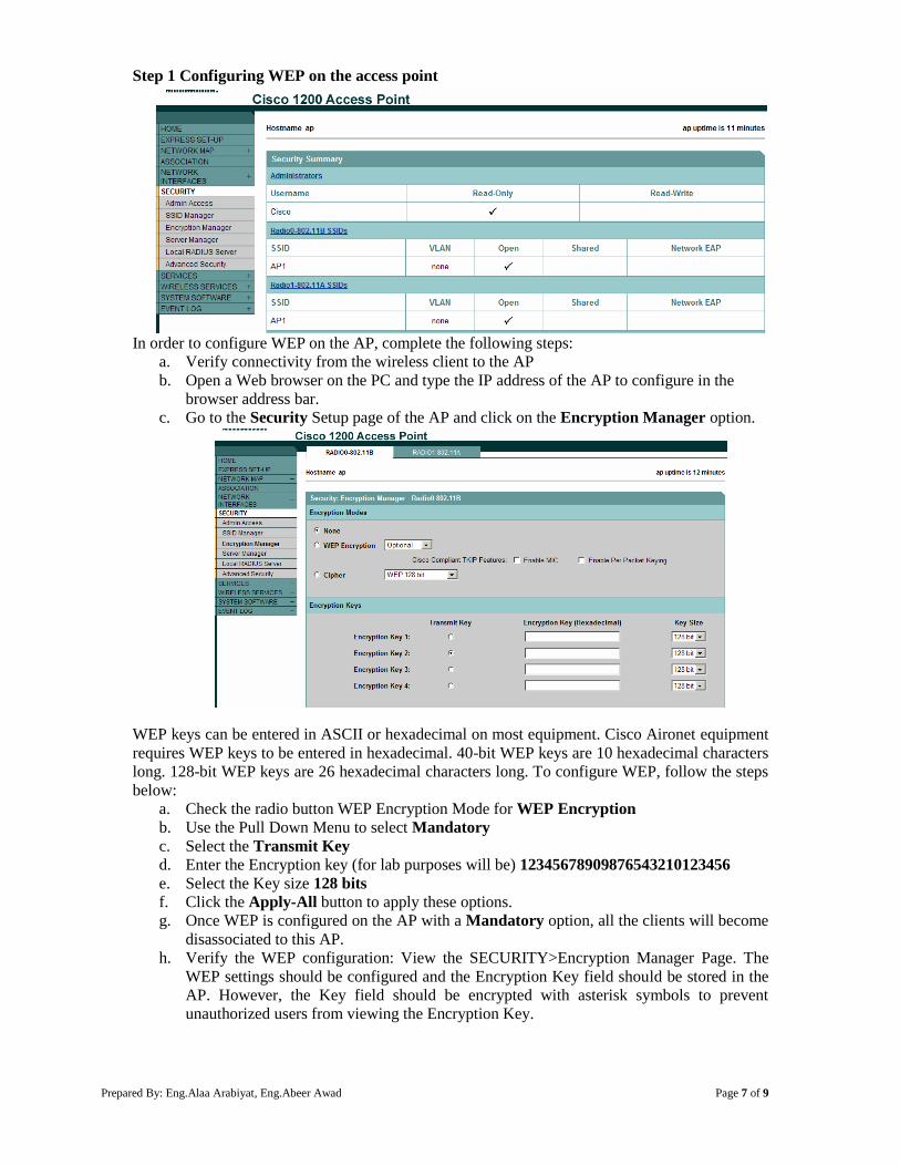
Prepared By: Eng.Alaa Arabiyat, Eng.Abeer Awad Page 7 of 9
Step 1 Configuring WEP on the access point
In order to configure WEP on the AP, complete the following steps:
a. Verify connectivity from the wireless client to the AP
b. Open a Web browser on the PC and type the IP address of the AP to configure in the
browser address bar.
c. Go to the Security Setup page of the AP and click on the Encryption Manager option.
WEP keys can be entered in ASCII or hexadecimal on most equipment. Cisco Aironet equipment
requires WEP keys to be entered in hexadecimal. 40-bit WEP keys are 10 hexadecimal characters
long. 128-bit WEP keys are 26 hexadecimal characters long. To configure WEP, follow the steps
below:
a. Check the radio button WEP Encryption Mode for WEP Encryption
b. Use the Pull Down Menu to select Mandatory
c. Select the Transmit Key
d. Enter the Encryption key (for lab purposes will be) 12345678909876543210123456
e. Select the Key size 128 bits
f. Click the Apply-All button to apply these options.
g. Once WEP is configured on the AP with a Mandatory option, all the clients will become
disassociated to this AP.
h. Verify the WEP configuration: View the SECURITY>Encryption Manager Page. The
WEP settings should be configured and the Encryption Key field should be stored in the
AP. However, the Key field should be encrypted with asterisk symbols to prevent
unauthorized users from viewing the Encryption Key.
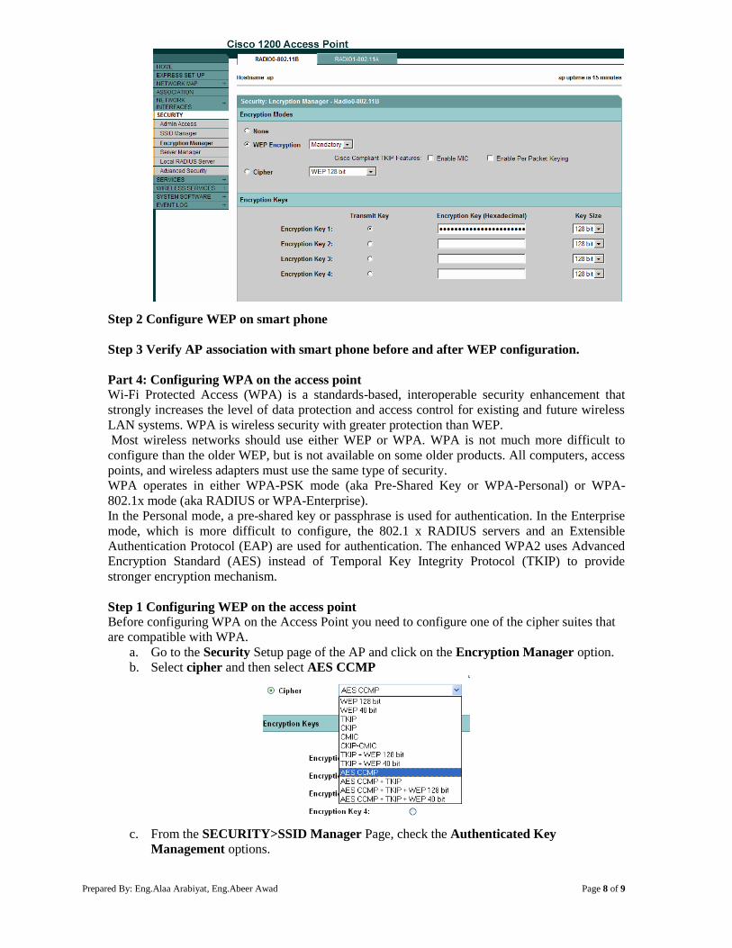
Prepared By: Eng.Alaa Arabiyat, Eng.Abeer Awad Page 8 of 9
Step 2 Configure WEP on smart phone
Step 3 Verify AP association with smart phone before and after WEP configuration.
Part 4: Configuring WPA on the access point
Wi-Fi Protected Access (WPA) is a standards-based, interoperable security enhancement that
strongly increases the level of data protection and access control for existing and future wireless
LAN systems. WPA is wireless security with greater protection than WEP.
Most wireless networks should use either WEP or WPA. WPA is not much more difficult to
configure than the older WEP, but is not available on some older products. All computers, access
points, and wireless adapters must use the same type of security.
WPA operates in either WPA-PSK mode (aka Pre-Shared Key or WPA-Personal) or WPA-
802.1x mode (aka RADIUS or WPA-Enterprise).
In the Personal mode, a pre-shared key or passphrase is used for authentication. In the Enterprise
mode, which is more difficult to configure, the 802.1 x RADIUS servers and an Extensible
Authentication Protocol (EAP) are used for authentication. The enhanced WPA2 uses Advanced
Encryption Standard (AES) instead of Temporal Key Integrity Protocol (TKIP) to provide
stronger encryption mechanism.
Step 1 Configuring WEP on the access point
Before configuring WPA on the Access Point you need to configure one of the cipher suites that
are compatible with WPA.
a. Go to the Security Setup page of the AP and click on the Encryption Manager option.
b. Select cipher and then select AES CCMP
c. From the SECURITY>SSID Manager Page, check the Authenticated Key
Management options.
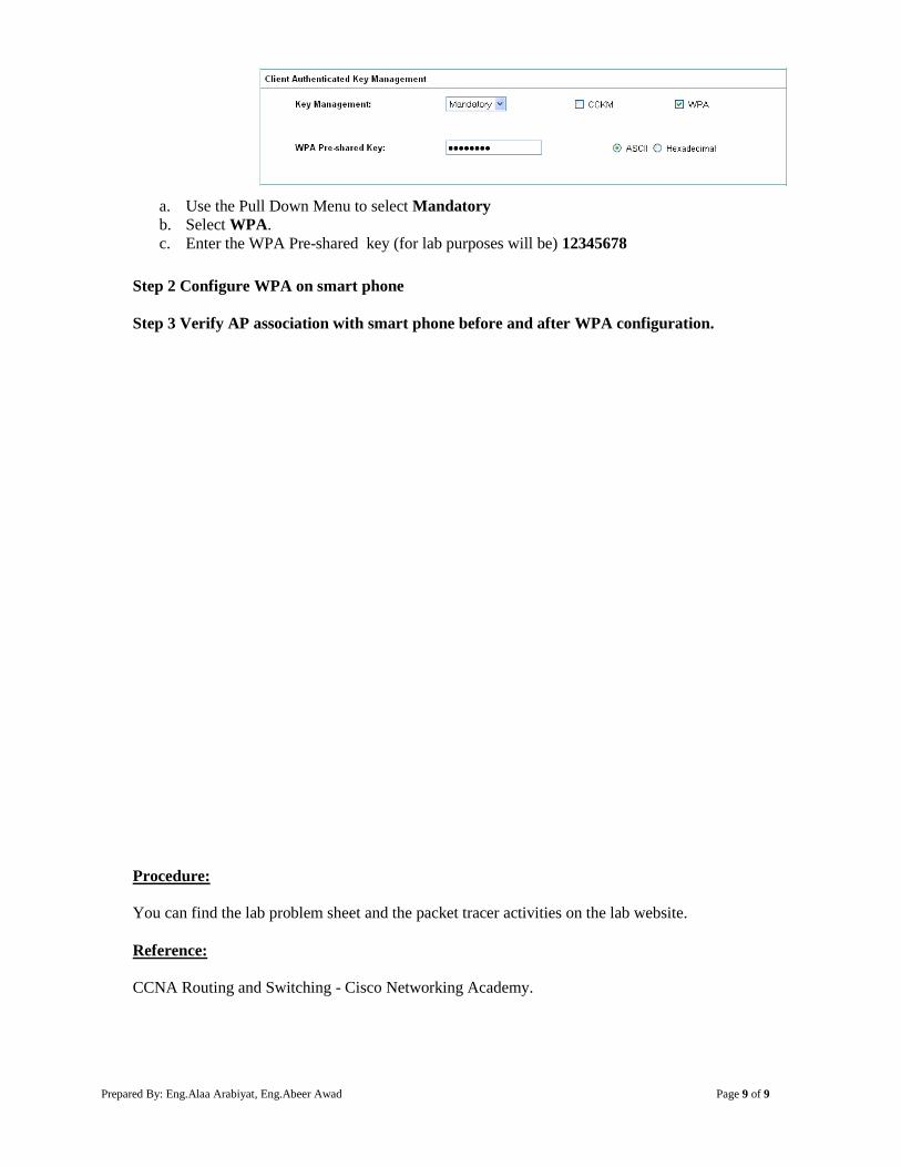
Prepared By: Eng.Alaa Arabiyat, Eng.Abeer Awad Page 9 of 9
a. Use the Pull Down Menu to select Mandatory
b. Select WPA.
c. Enter the WPA Pre-shared key (for lab purposes will be) 12345678
Step 2 Configure WPA on smart phone
Step 3 Verify AP association with smart phone before and after WPA configuration.
Procedure:
You can find the lab problem sheet and the packet tracer activities on the lab website.
Reference:
CCNA Routing and Switching - Cisco Networking Academy.
Prepared By: Eng.Alaa Arabiyat Page 1 of 9
University of Jordan
Faculty of Engineering & Technology
Computer Engineering Department
Advance Networks Laboratory 0907529
Exp.9 Dynamic Host Configuration Protocol (DHCP)
Objectives
1. Describe the operation of DHCP in a small-to-medium-sized business network.
2. Configure a router as a DHCP server.
3. Configure a router as a DHCP client.
4. Troubleshoot a DHCP configuration in a switched network.
1. Introduction
Every device that connects to a network needs a unique IP address. Network administrators
assign static IP addresses to routers, servers, printers, and other network devices whose locations
(physical and logical) are not likely to change. These are usually devices that provide services to
users and devices on the network; therefore, the addresses assigned to them should remain
constant. Additionally, static addresses enable administrators to manage these devices remotely. It
is easier for network administrators to access a device when they can easily determine its IP
address.
However, computers and users in an organization often change locations, physically and
logically. It can be difficult and time consuming for administrators to assign new IP addresses
every time an employee moves. Additionally, for mobile employees working from remote
locations, manually setting the correct network parameters can be challenging. Even for desktop
clients, the manual assignment of IP addresses and other addressing information presents an
administrative burden, especially as the network grows.
Introducing a Dynamic Host Configuration Protocol (DHCP) server to the local network
simplifies IP address assignment to both desktop and mobile devices. Using a centralized DHCP
server enables organizations to administer all dynamic IP address assignments from a single
server. This practice makes IP address management more effective and ensures consistency
across the organization, including branch offices.
2. DHCPv4 Operation
DHCPv4 assigns IPv4 addresses and other network configuration information dynamically.
Because desktop clients typically make up the bulk of network nodes, DHCPv4 is an extremely
useful and timesaving tool for network administrators.
A dedicated DHCPv4 server is scalable and relatively easy to manage. However, in a small
branch or SOHO location, a Cisco router can be configured to provide DHCPv4 services without
the need for a dedicated server. A Cisco IOS feature set (called ”Easy IP)” offers an optional,
full-featured DHCPv4 server.
DHCPv4 includes three different address allocation mechanisms to provide flexibility when
assigning IP addresses:
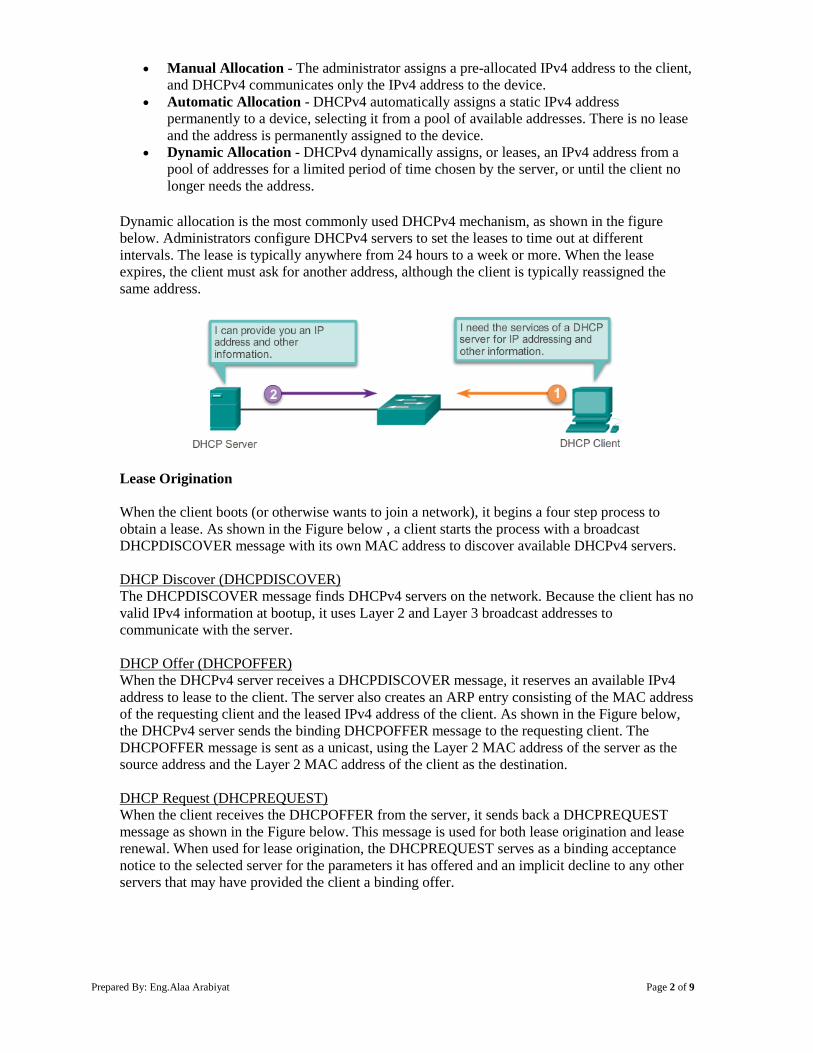
Prepared By: Eng.Alaa Arabiyat Page 2 of 9
Manual Allocation - The administrator assigns a pre-allocated IPv4 address to the client,
and DHCPv4 communicates only the IPv4 address to the device.
Automatic Allocation - DHCPv4 automatically assigns a static IPv4 address
permanently to a device, selecting it from a pool of available addresses. There is no lease
and the address is permanently assigned to the device.
Dynamic Allocation - DHCPv4 dynamically assigns, or leases, an IPv4 address from a
pool of addresses for a limited period of time chosen by the server, or until the client no
longer needs the address.
Dynamic allocation is the most commonly used DHCPv4 mechanism, as shown in the figure
below. Administrators configure DHCPv4 servers to set the leases to time out at different
intervals. The lease is typically anywhere from 24 hours to a week or more. When the lease
expires, the client must ask for another address, although the client is typically reassigned the
same address.
Lease Origination
When the client boots (or otherwise wants to join a network), it begins a four step process to
obtain a lease. As shown in the Figure below , a client starts the process with a broadcast
DHCPDISCOVER message with its own MAC address to discover available DHCPv4 servers.
DHCP Discover (DHCPDISCOVER)
The DHCPDISCOVER message finds DHCPv4 servers on the network. Because the client has no
valid IPv4 information at bootup, it uses Layer 2 and Layer 3 broadcast addresses to
communicate with the server.
DHCP Offer (DHCPOFFER)
When the DHCPv4 server receives a DHCPDISCOVER message, it reserves an available IPv4
address to lease to the client. The server also creates an ARP entry consisting of the MAC address
of the requesting client and the leased IPv4 address of the client. As shown in the Figure below,
the DHCPv4 server sends the binding DHCPOFFER message to the requesting client. The
DHCPOFFER message is sent as a unicast, using the Layer 2 MAC address of the server as the
source address and the Layer 2 MAC address of the client as the destination.
DHCP Request (DHCPREQUEST)
When the client receives the DHCPOFFER from the server, it sends back a DHCPREQUEST
message as shown in the Figure below. This message is used for both lease origination and lease
renewal. When used for lease origination, the DHCPREQUEST serves as a binding acceptance
notice to the selected server for the parameters it has offered and an implicit decline to any other
servers that may have provided the client a binding offer.
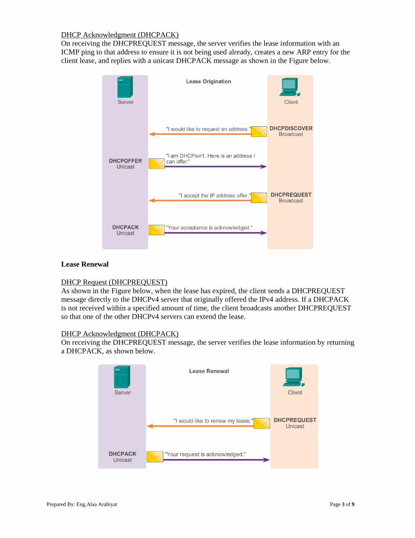
Prepared By: Eng.Alaa Arabiyat Page 3 of 9
DHCP Acknowledgment (DHCPACK)
On receiving the DHCPREQUEST message, the server verifies the lease information with an
ICMP ping to that address to ensure it is not being used already, creates a new ARP entry for the
client lease, and replies with a unicast DHCPACK message as shown in the Figure below.
Lease Renewal
DHCP Request (DHCPREQUEST)
As shown in the Figure below, when the lease has expired, the client sends a DHCPREQUEST
message directly to the DHCPv4 server that originally offered the IPv4 address. If a DHCPACK
is not received within a specified amount of time, the client broadcasts another DHCPREQUEST
so that one of the other DHCPv4 servers can extend the lease.
DHCP Acknowledgment (DHCPACK)
On receiving the DHCPREQUEST message, the server verifies the lease information by returning
a DHCPACK, as shown below.
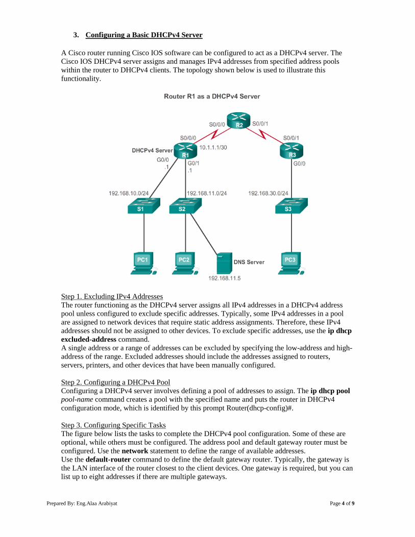
Prepared By: Eng.Alaa Arabiyat Page 4 of 9
3. Configuring a Basic DHCPv4 Server
A Cisco router running Cisco IOS software can be configured to act as a DHCPv4 server. The
Cisco IOS DHCPv4 server assigns and manages IPv4 addresses from specified address pools
within the router to DHCPv4 clients. The topology shown below is used to illustrate this
functionality.
Step 1. Excluding IPv4 Addresses
The router functioning as the DHCPv4 server assigns all IPv4 addresses in a DHCPv4 address
pool unless configured to exclude specific addresses. Typically, some IPv4 addresses in a pool
are assigned to network devices that require static address assignments. Therefore, these IPv4
addresses should not be assigned to other devices. To exclude specific addresses, use the ip dhcp
excluded-address command.
A single address or a range of addresses can be excluded by specifying the low-address and high-
address of the range. Excluded addresses should include the addresses assigned to routers,
servers, printers, and other devices that have been manually configured.
Step 2. Configuring a DHCPv4 Pool
Configuring a DHCPv4 server involves defining a pool of addresses to assign. The ip dhcp pool
pool-name command creates a pool with the specified name and puts the router in DHCPv4
configuration mode, which is identified by this prompt Router(dhcp-config)#.
Step 3. Configuring Specific Tasks
The figure below lists the tasks to complete the DHCPv4 pool configuration. Some of these are
optional, while others must be configured. The address pool and default gateway router must be
configured. Use the network statement to define the range of available addresses.
Use the default-router command to define the default gateway router. Typically, the gateway is
the LAN interface of the router closest to the client devices. One gateway is required, but you can
list up to eight addresses if there are multiple gateways.
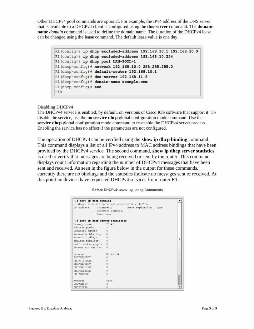
Prepared By: Eng.Alaa Arabiyat Page 5 of 9
Other DHCPv4 pool commands are optional. For example, the IPv4 address of the DNS server
that is available to a DHCPv4 client is configured using the dns-server command. The domain-
name domain command is used to define the domain name. The duration of the DHCPv4 lease
can be changed using the lease command. The default lease value is one day.
Disabling DHCPv4
The DHCPv4 service is enabled, by default, on versions of Cisco IOS software that support it. To
disable the service, use the no service dhcp global configuration mode command. Use the
service dhcp global configuration mode command to re-enable the DHCPv4 server process.
Enabling the service has no effect if the parameters are not configured.
The operation of DHCPv4 can be verified using the show ip dhcp binding command.
This command displays a list of all IPv4 address to MAC address bindings that have been
provided by the DHCPv4 service. The second command, show ip dhcp server statistics,
is used to verify that messages are being received or sent by the router. This command
displays count information regarding the number of DHCPv4 messages that have been
sent and received. As seen in the figure below in the output for these commands,
currently there are no bindings and the statistics indicate no messages sent or received. At
this point no devices have requested DHCPv4 services from router R1.
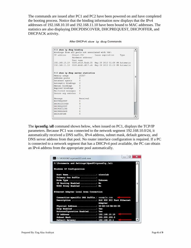
Prepared By: Eng.Alaa Arabiyat Page 6 of 9
The commands are issued after PC1 and PC2 have been powered on and have completed
the booting process. Notice that the binding information now displays that the IPv4
addresses of 192.168.10.10 and 192.168.11.10 have been bound to MAC addresses. The
statistics are also displaying DHCPDISCOVER, DHCPREQUEST, DHCPOFFER, and
DHCPACK activity.
The ipconfig /all command shown below, when issued on PC1, displays the TCP/IP
parameters. Because PC1 was connected to the network segment 192.168.10.0/24, it
automatically received a DNS suffix, IPv4 address, subnet mask, default gateway, and
DNS server address from that pool. No router interface configuration is required. If a PC
is connected to a network segment that has a DHCPv4 pool available, the PC can obtain
an IPv4 address from the appropriate pool automatically.
Prepared By: Eng.Alaa Arabiyat Page 7 of 9
What is DHCP Relay?
In a complex hierarchical network, enterprise servers are usually located in a server farm. These
servers may provide DHCP, DNS, TFTP, and FTP services for the network. Network clients are
not typically on the same subnet as those servers. In order to locate the servers and receive
services, clients often use broadcast messages.
In the figure below, PC1 is attempting to acquire an IPv4 address from a DHCP server using a
broadcast message. In this scenario, router R1 is not configured as a DHCPv4 server and does not
forward the broadcast. Because the DHCPv4 server is located on a different network, PC1 cannot
receive an IP address using DHCP.
In the figure below, PC1 is attempting to renew its IPv4 address. To do so, the ipconfig /release
command is issued. Notice that the IPv4 address is released and the address is shown to be
0.0.0.0. Next, the ipconfig /renew command is issued. This command causes PC1 to broadcast a
DHCPDISCOVER message. The output shows that PC1 is unable to locate the DHCPv4 server.
Because routers do not forward broadcasts, the request is not successful.
Prepared By: Eng.Alaa Arabiyat Page 8 of 9
As a solution to this problem, an administrator can add DHCPv4 servers on all the subnets.
However, running these services on several computers creates additional cost and administrative
overhead.
A better solution is to configure a Cisco IOS helper address. This solution enables a router to
forward DHCPv4 broadcasts to the DHCPv4 server. When a router forwards address
assignment/parameter requests, it is acting as a DHCPv4 relay agent. In the example topology,
PC1 would broadcast a request to locate a DHCPv4 server. If R1 was configured as a DHCPv4
relay agent, it would forward the request to the DHCPv4 server located on subnet 192.168.11.0.
As shown below, the interface on R1 receiving the broadcast is configured with the ip helper-
address interface configuration mode command. The address of the DHCPv4 server is
configured as the only parameter.
When R1 has been configured as a DHCPv4 relay agent, it accepts broadcast requests for the
DHCPv4 service and then forwards those requests as a unicast to the IPv4 address 192.168.11.6.
The show ip interface command is used to verify the configuration.
As shown below, PC1 is now able to acquire an IPv4 address from the DHCPv4 server.
Prepared By: Eng.Alaa Arabiyat Page 9 of 9
4. Configure DHCPv4 Client
Sometimes, Cisco routers in small office/home office (SOHO) and branch sites have to be
configured as DHCPv4 clients in a similar manner to client computers. The method used depends
on the ISP. However, in its simplest configuration, the Ethernet interface is used to connect to a
cable or DSL modem. To configure an Ethernet interface as a DHCP client, use the ip address
dhcp interface configuration mode command.
In the figure below, assume that an ISP has been configured to provide select customers with IP
addresses from the 209.165.201.0/27 network range. After the G0/1 interface is configured with
the ip address dhcp command, the show ip interface g0/1 command confirms that the interface
is up and that the address was allocated by a DHCPv4 server.
Procedure:
You can find the lab problem sheet and the packet tracer activities on the lab website.
Reference:
CCNA Routing and Switching - Cisco Networking Academy.