University of Groningen Microstructure of reaction zone in ... · Cast duplex stainless steel ......
9
University of Groningen Microstructure of reaction zone in WCp/duplex stainless steels matrix composites processing by laser melt injection Do Nascimento, A. M.; Ocelik, Vaclav; Ierardi, M. C. F.; De Hosson, J.T.M. Published in: Surface & Coatings Technology DOI: 10.1016/j.surfcoat.2007.08.065 IMPORTANT NOTE: You are advised to consult the publisher's version (publisher's PDF) if you wish to cite from it. Please check the document version below. Document Version Publisher's PDF, also known as Version of record Publication date: 2008 Link to publication in University of Groningen/UMCG research database Citation for published version (APA): Do Nascimento, A. M., Ocelik, V., Ierardi, M. C. F., & De Hosson, J. T. M. (2008). Microstructure of reaction zone in WCp/duplex stainless steels matrix composites processing by laser melt injection. Surface & Coatings Technology, 202(10), 2113-2120. DOI: 10.1016/j.surfcoat.2007.08.065 Copyright Other than for strictly personal use, it is not permitted to download or to forward/distribute the text or part of it without the consent of the author(s) and/or copyright holder(s), unless the work is under an open content license (like Creative Commons). Take-down policy If you believe that this document breaches copyright please contact us providing details, and we will remove access to the work immediately and investigate your claim. Downloaded from the University of Groningen/UMCG research database (Pure): http://www.rug.nl/research/portal. For technical reasons the number of authors shown on this cover page is limited to 10 maximum. Download date: 10-02-2018
Transcript of University of Groningen Microstructure of reaction zone in ... · Cast duplex stainless steel ......

University of Groningen
Microstructure of reaction zone in WCp/duplex stainless steels matrix composites processingby laser melt injectionDo Nascimento, A. M.; Ocelik, Vaclav; Ierardi, M. C. F.; De Hosson, J.T.M.
Published in:Surface & Coatings Technology
DOI:10.1016/j.surfcoat.2007.08.065
IMPORTANT NOTE: You are advised to consult the publisher's version (publisher's PDF) if you wish to cite fromit. Please check the document version below.
Document VersionPublisher's PDF, also known as Version of record
Publication date:2008
Link to publication in University of Groningen/UMCG research database
Citation for published version (APA):Do Nascimento, A. M., Ocelik, V., Ierardi, M. C. F., & De Hosson, J. T. M. (2008). Microstructure of reactionzone in WCp/duplex stainless steels matrix composites processing by laser melt injection. Surface &Coatings Technology, 202(10), 2113-2120. DOI: 10.1016/j.surfcoat.2007.08.065
CopyrightOther than for strictly personal use, it is not permitted to download or to forward/distribute the text or part of it without the consent of theauthor(s) and/or copyright holder(s), unless the work is under an open content license (like Creative Commons).
Take-down policyIf you believe that this document breaches copyright please contact us providing details, and we will remove access to the work immediatelyand investigate your claim.
Downloaded from the University of Groningen/UMCG research database (Pure): http://www.rug.nl/research/portal. For technical reasons thenumber of authors shown on this cover page is limited to 10 maximum.
Download date: 10-02-2018

Microstructure of reaction zone in WCp/duplex stainless steels matrixcomposites processing by laser melt injection
A.M. Do Nascimento a, V. Ocelík b,⁎, M.C.F. Ierardi a, J.Th.M. De Hosson b
a Department of Materials Science, Faculty of Mechanical Engineering, State University of Campinas,UNICAMP, P.O. Box 6122, 13083-970 Campinas — SP, Brazil
b Department of Applied Physics, Zernike Institute for Advanced Materials and Netherlands Institute for Metals Research,University of Groningen, Nijenborgh 4, 9747 AG Groningen, The Netherlands
Received 13 June 2007; accepted in revised form 28 August 2007Available online 7 September 2007
Abstract
The laser melt injection (LMI) process has been used to create a metal matrix composite consisting of 80μm sized multi-grain WC particlesembedded in three cast duplex stainless steels. The microstruture was investigated by scanning electron microscopy with integrated EDS andelectron back-scatter diffraction/orientation imaging microscopy. In particular the search of the processing parameters, e.g. laser power density,laser beam scanning speed and powder flow rate, to obtain crack free and WCp containing surface layer, has been examined. Before the injectionof ceramic particles into remelted surface layer, the influence of processing parameters of laser surface remelting on the microstructure andproperties of selected duplex steels was also investigated. Although after simple laser surface remelting the austenitic phase is almost not presentinside remelted layer, in the case of LMI the austenite was observed in vicinity of WC particles, due to increase of carbon content acting asaustenite stabilizer. The diffusion of carbon in the reaction zone results also in a formation of W2C phase in the neighborhood of WC particles witha strong orientation relationship between them. The maximum volume fraction of the particles achieved in the metal matrix composite layer wasabout 10% and a substantial increase in hardness was observed, i.e. 575 HV0.2 for the matrix with embedded particles in comparison to 290HV0.2 for untreated cast duplex stainless steels.© 2007 Elsevier B.V. All rights reserved.
Keywords: Laser treatment; Metal matrix composite; Electron back-scatter diffraction; Duplex stainless steel
1. Introduction
The injection of ceramic particles into a melt pool, which iscreated in the top of a metal substrate by a high power laserbeam [1–4] may form metal matrix-ceramic composite (MMC)layers on metal surfaces. The main goal of this laser meltinjection (LMI) process is to improve mechanical and chemicalproperties of metal surfaces such as steels, Al or Ti alloys.Surface layers prepared by the LMI process exhibit strongbonding and no large discontinuity of properties at the layer/substrate interface [5].
The overall properties of the MMC layer depend on thespecific properties and amount of injected ceramic particles, on
the microstructure of the laser beam remelted substrates and onthe presence and properties of new phases formed by chemicalreactions between matrix and particles. These phases are mainlypresent at the particle/matrix interface in the so-called reactionzone.
Cast duplex stainless steel (CDSS) have been used in manyindustrial processes for special purposes in the chemical,petrochemical, fertilizer and cellulose industries [6–8]. They aregenerally used as compressor cylinders, digester valves, feedscrews, impellers, liners, pump casings, runway light fixtures(aircraft carriers, airports), safety valves, sprocket wheels,pistons, seal rings (centrifugal pumps) and valve parts due toexcellent corrosion resistance. However, their mechanicalproperties, mainly hardness and wear resistance, may beinsufficient in some applications and therefore decreasing thelife time of the component [9]. In the literature there are several
Available online at www.sciencedirect.com
Surface & Coatings Technology 202 (2008) 2113–2120www.elsevier.com/locate/surfcoat
⁎ Corresponding author. Tel.: +31 50 363 3407; fax: +31 50 363 4881.E-mail address: [email protected] (V. Ocelík).
0257-8972/$ - see front matter © 2007 Elsevier B.V. All rights reserved.doi:10.1016/j.surfcoat.2007.08.065
attempts to improve the surface properties of different steels viaformation of coatings by laser surface modification techniquesmainly by laser cladding and alloying, using WC particlesmixed with Co or Ni alloys as clad powders [10–17].
This work is aimed at examining the microstructural changesin the three types of CDSSs representing different groups ofthese materials after laser surface remelting and LMI of WCparticles. The final objective of the project is to improve themechanical properties and the wear resistance of differentduplex steels.
2. Experimental details
Laser experiments have been carried out with a continuouswave 2kW Rofin Sinar Nd-YAG laser. The detailed sketch forlaser melt injection set-up can be found elsewhere [3,5]. Thelaser beam is used to create melt pool at the surface of movingmetallic substrate and simultaneously ceramic particles areinjected into the melt pool just behind the laser beam using glassnozzle and Argon as carrier gas. The laser beam is positioned atan 11° angle with respect to the substrate surface normal to
avoid harmful reflections from the specimen back into theoptical fiber. Argon was used as a shielding gas to protect thelens as well as to reduce oxidation of the specimen. The spotsize of the laser beam on the work piece was 2.8mm with anapproximately Gaussian distribution of laser beam power. Fouraxes CNC table was employed for specimen movement.
The CDSSs used in our experiments with their chemicalcompositions, Creq/Nieq ratios and estimated pitting resistanceequivalents [18,33] are shown in Table 1. Circular plates withdimensions ϕ50mm × 10mm were used as a substrate material.Before laser treatment, the surface has been sandblasted topromote the absorption of the laser light. A powder feedingsystem Sulzer Metco Twin 10C supplied WC multi-grainparticles with an average size of about 80μm, using Ar as acarrier gas with flow rate of 67ml/s. The particles were injectedinto the melt pool at an angle of 37° with respect to the surfacenormal.
Standard light microscopy (Olympus Vanox-AHTM), scan-ning electron microscopy (SEM Philips XL30 FEG), Orienta-tion Imaging Microscopy (TSL attachment to Philips XL30FEG) and XRD diffraction (Philips PW-1830, CuKα radiation)
Table 1The chemical composition (in wt.%) of the three types of CDSSs: ASTMA890 grade 1A (free of nitrogen), ASTMA890 grade 3A (with nitrogen and without Cu) andASTM A890 grade 6A (Super Duplex)
Alloy C Cr Ni Mn Si Mo S P Cu N W Cr/Ni PRE
1A 0.04 25.01 5.53 0.78 0.99 2.11 0.006 0.026 3.10 3.52 31.973A 0.03 25.33 5.38 0.84 0.90 2.13 0.005 0.025 0.19 2.70 35.966A 0.02 25.96 7.93 0.83 0.97 3.63 0.008 0.024 0.82 0.24 0.78 2.17 43.07
All compositions are balanced to 100% by iron. In last two columns the ratio of Cr and Ni equivalents, and pitting resistant equivalent are shown, respectively. Creq=%Cr+%Mo+0.7x%Nb [18]; Nieq=%Ni+35x%C+20x%N+0.25x%Cu [18]; PRE=%Cr+3.3(%Mo+0.5%W)+16%N [33].
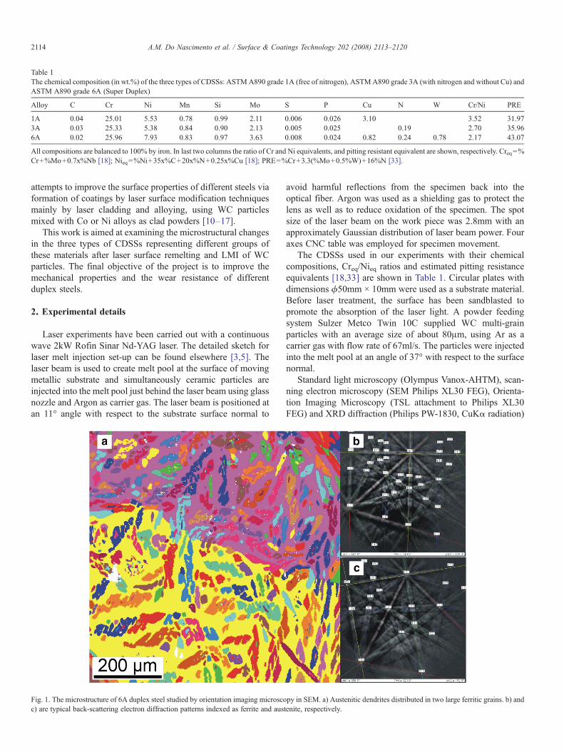
Fig. 1. The microstructure of 6A duplex steel studied by orientation imaging microscopy in SEM. a) Austenitic dendrites distributed in two large ferritic grains. b) andc) are typical back-scattering electron diffraction patterns indexed as ferrite and austenite, respectively.
2114 A.M. Do Nascimento et al. / Surface & Coatings Technology 202 (2008) 2113–2120

were used to study particle distribution, microstructure andmicrostructural orientation relationships (OR) in WCp/CDSSlayers prepared by injection of multi-grain WC particles intoCDSS substrates.
Vickers hardness measurement is used to obtain informationof the mechanical properties of transformed zone and substrate.The measurements were performed on cross-sections of thesamples that have been ground and polished to eliminate themacro-roughness.
3. Results
During solidification the CDSS first solidifies as ferrite andwhen temperature decreases, austenite is developed [19]. Thecharacteristic microstructure for CDSSs is the microstructure ofaustenitic islands in the ferritic matrix. Fig. 1a shows this typicalmicrostructure for 6A alloy.
The grains of ferrite are coarse with a size ranging from 0.5 to1mm and the mean size of austenite dendrites is about 30μmarranged in a few hundreds of micrometers long lines. As resultsof X-ray diffraction confirmed (see Fig. 4), austenite and ferriteare the main constituent phases for all three substrate alloys. Thecontent of austenitic phasemeasured byOIMwas almost the same(about 50%) for alloys 1A and 3A, but slightly lower (43%) foralloy 6A. A more detailed study of the orientation relationshipbetween ferritic and austenitic grains in these three alloys showedthat some differences in intensity of OR exist [20].
Fig. 2a shows a typical transversal cross-section of a singlelaser track produced by laser surface remelting. The aim ofremelting experiments was to study the behavior of these alloysin the interaction with high power laser beam and to find aprocessing window of laser parameters for the further laser meltinjection treatment. A characteristic shape of remelted zone forGaussian type of beam energy distribution inside laser beamwas observed. A substantial number of single remelting trackswere realized varying laser beam energy between 620 and1750W and laser beam scanning speed between 8.33 and50mm/s. The width of the remelted zone was close to the widthof laser beam spot and did change only slightly with laser beamenergy and scanning speed. The dependence of the maximaldepth of remelted zone on laser beam power and scanning speedis summarized in Fig. 2b. As the final thickness of thetransformed zone created by a partial overlapping of subsequentlaser tracks should not be less than 300μm, we limited ourprocessing window, as marked in Fig. 2b by the dashed line. It isimportant to note, that for all combinations of processingparameters the remelted single tracks were free of cracks orpores.
Fig. 3 shows the microstructure of the remelted surface andsubstrate in the area of overlapping of two laser tracks studied byOIM on transversal cross-section, using the overlap ratio of 33%.Fig. 3a highlights the present phases, whereas Fig. 3b shows
Fig. 2. a) Optical micrograph of characteristic shape of laser beam remeltedsurface area in a perpendicular cross-section made on 1A alloy at laser power1750 W and scanning speed of 20 mm/s. b) Maximal depth of remelted singlelaser track as a function of laser power and laser beam scanning speed.
Fig. 3. OIM of remelted microstructure in the area of two overlapped laser tracksin 1A alloy. a) Phase mapping shows a predominant presence of ferrite (darkphase) in the remelted zone while in the substrate the both phases are almostequally present. b) Inverse pole figure from the same area shows the orientationof detected ferritic grains.
2115A.M. Do Nascimento et al. / Surface & Coatings Technology 202 (2008) 2113–2120

ferritic grains with different orientations. It is clear that afterresolidification the microstructure is substantially changed.Fig. 3a demonstrates that the ferritic phase is dominant inremelted zone.Austenite nuclei are present at the grain boundariesof ferritic grains, but due to relatively high cooling rates duringlaser remelting, austenite is not further developed. Fig. 3b showsthat the ferrite grains in remelted zone close to the interface withsubstrate follow the crystallographic orientation of grains fromsubstrate but more close to the surface a new system of equiaxialferritic grains with size between 50 and 200μm is formed.
The predominance of ferritic phase after laser remelting wasconfirmed by X-ray diffraction phase analysis for all threeduplex steels. Fig. 4 presents XRD diffraction spectra of allthree CDSSs for untreated and remelted state. It is possible tosee that the austenite peaks decrease their relative intensities ordisappear completely after laser remelting. The XRD spectraafter remelting do not reveal any new peaks.
Fig. 5 shows the microhardness profiles of 3A alloy samplestreated with different laser remelting parameters. An increasebetween 30 and 50% in hardness was observed in the remeltedregion for low and high scanning speeds, respectively. Theincrease of the hardness may be explained by microstructuralchanges, which are usually considered as important factor indriving the increase of hardness in the laser surface remeltedalloys [21]. The laser beam scanning speed is one of the mostimportant parameters because it mainly determines the solidifi-cation rate and the final microstructure. Between remelted zoneand substrate material a heat affected zone is present with athickness of about 200μm for all scanning speeds. The hardnessinside this zone after a sharp change gradually decreases to thevalue of about 270HV0.2, which is a typical value for non-treatedmaterial.
WC particles with a mean diameter of 80μm were injected inCDSSs round substrates (ϕ = 50mm) 10mm thick. Threesubsequent laser tracks were created during rotation of thesubstrate under treated Nd:YAG laser beam using a synchro-nized lateral movement in such a way, that after one rotation thedisplacement between laser tracks of 1.5mm is achieved. Wefound that the processing window for successful laser melt
injection is quite small. A special attention has been paid to set-up the regime, when particles have sufficient velocity topenetrate into the melt and they are not overheated or melted bythe laser beam when they reach the melt substrate surface. Thisconstraint requires an existence of melt pool ‘tail’ after the laserilluminated area [5] which shifts the processing windowstowards higher scanning speeds and laser power densities. Onthe other side the higher laser power density can easily overheator melt that part of injected particles which are even in a shortcontact with laser beam. These two rather opposite constraintssqueeze the processing window for laser melt injection as it was
Fig. 4. Comparison of XRD spectra measured before (S) and after (R) lasersurface remelting for all three CDSSs from Table 1. Positions of main XRDspectra lines for austenite and ferrite phase from JCPDS database are indicated.
Fig. 5. Microhardness depth profiles measured on transversal cross-sections oflaser tracks made with different processing parameters on 3A alloy. Each pointshows the average value from three indents performed at the same depth. Thefirst measurement starts at depth of 50 μm from the surface. Vertical line marksthe position of boundary between the remelted and the substrate material.
Fig. 6. a) SEM micrograph of WC particles. b) Light microscopy micrographfrom perpendicular cross-section of three subsequent laser tracks with injectedWC particles. Contrast for WC is enhanced via image manipulation software toestimate the volume fraction of injected particles.
2116 A.M. Do Nascimento et al. / Surface & Coatings Technology 202 (2008) 2113–2120

observed earlier in case of Al, Ti and their alloys [1–5]. Due tothe small size of processing window; it is quite difficult tomanipulate the amount of injected particles, especially when ahigher volume fraction of injected particles is required. Anincrease of powder feeding rate over some critical value alwaysresults in the substantial cracking of solidified laser track withcracks oriented mainly perpendicular to the cladding direction.Fig. 6a shows the shape and size of WC particles beforeinjection and Fig. 6b is the optical micrograph of a transversalcross-section showing the distribution of injected particles inthree partially overlapping laser tracks made with laser power of1000W, laser beam scanning speed of 13.3mm/s and powderfeeding rate of 73mg/s. This combination of processingparameters leads to the highest volume density of injectedparticles (8–10vol.%) without forming cracks inside the pro-cessed volume.
Fig. 7 shows the result of microhardness measurementsperformed on perpendicular cross-sections of LMI tracks tocharacterize hardness of the material between injected particles.After comparison with Fig. 5 it is clear that laser melt injectionof WC particles increases the hardness more than simple lasersurface remelting. The hardness is now almost doubled incomparison with non-treated substrates. This suggests that asubstantial amount of W and C must be dissolved in the matrix.This was confirmed by EDS measurements, when an averagevalue of 2.1at.% of W was measured in matrix areas betweenindividual particles. One may conclude from it, that althoughduring the LMI process a direct contact between injectedparticle and laser beam is minimized, some of the particles mustbe in a short contact with laser beam and therefore their surfacehas been melted. This melt was during injection mixed with themelt of substrate and formed a new matrix composition. Resultsin Fig. 7 also confirm that hardness value of the matrix afterinjection does not depend on duplex steel composition, whilethe initial hardness of 6a duplex steel substrate is a little bithigher than hardness for two others.
Fig. 8 demonstrates the XRD diffraction spectra taken fromthe surfaces of all three duplex steels treated by LMI process.No other phases than ferrite, austenite and WC were detected.However, from the higher relative intensity of austenite peaks incomparison with the remelting material (Fig. 4) one may expectthat the matrix contains more austenite than just remelted lasertrack. The presence of the austenitic phase near injected WCparticles was confirmed later by the phase contrast observationin OIM (see Fig. 10b). More detailed microstructural analysisconfirms the presence of other phases, especially in the vicinityof WC particles, but probably due to their small quantities theyhave not been identified by XRD.
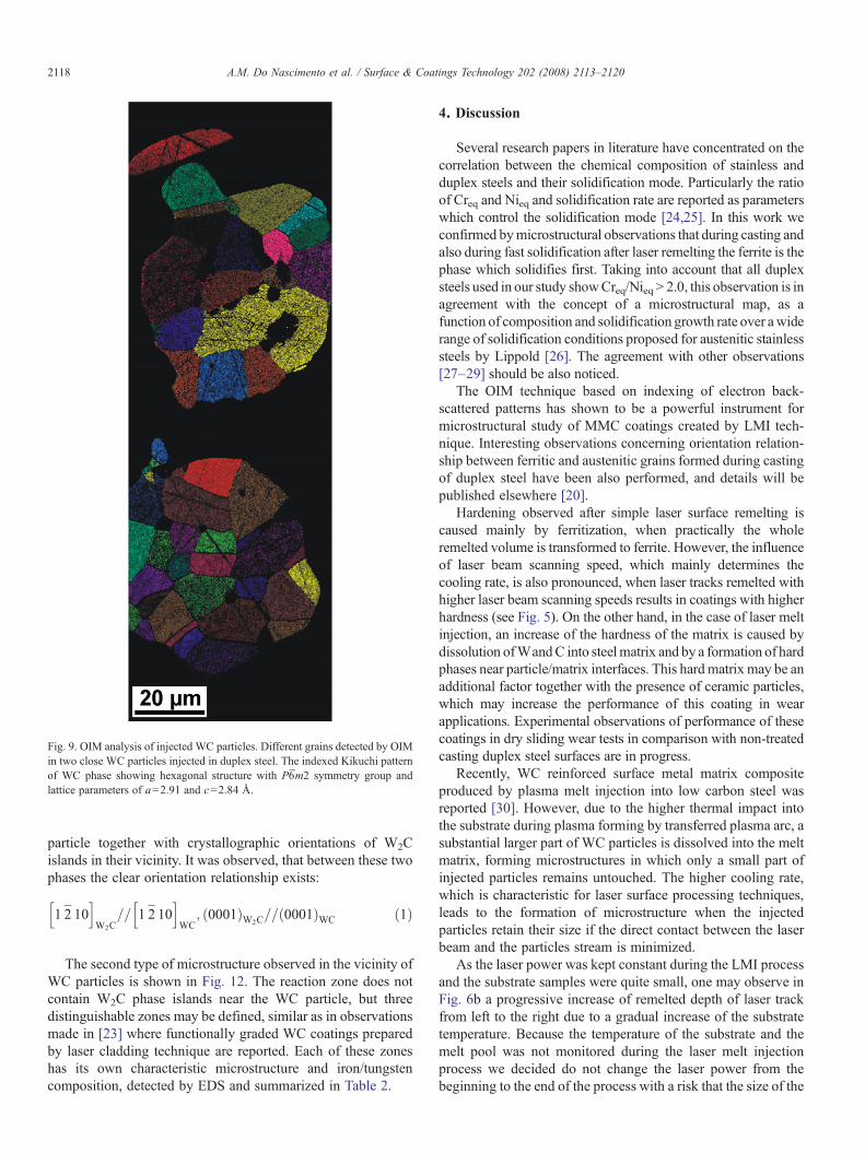
OIM mapping [22] was also used to study the details of themicrostructure formed during laser melt injection. Fig. 9demonstrates OIM mapping of two close particles injected induplex steel matrix. It is seen that each WC particle containsmany individual grains with an average size of about 10–20μm.
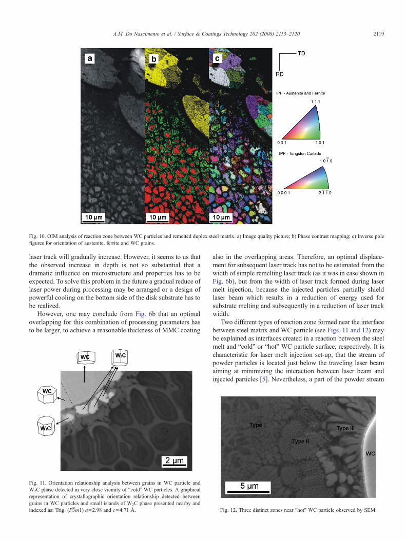
Fig. 10 summarizes oriented image microscopy analysismade in the vicinity of WC particles injected into duplex steelmatrix. The image quality map shown in Fig. 10a demonstratesthat a relatively narrow dark area (∼ 10μm) around each particleexists. Inside this area the quality of the back-scattereddiffraction patterns is too low making indexing impossible.The phase contrast mapping (Fig. 10b) clearly identifies the WCphase (yellow) inside the particles, the austenite (green) indistances between 10 and 50μm from particles graduallydecreases with this distance and finally the ferrite (red) whichgradually increases its presents in the same area.
Basically two different types of microstructures inside thereaction zone between WC particles and steel surrounding wereobserved. Fig. 11 shows one of them, when W2C phase islandsare detected nearby WC particles. More far from the WCparticle the individual cells with ferritic cores and austeniticshells around are present, as Fig. 10 demonstrates. The W2Cislands provide sometimes relatively very good EBSD pattern,which can be indexed and crystallographic orientation of thisphase may be compared with crystallographic orientation ofgrains in WC particle. Fig. 11 also shows graphically thecrystallographic orientation of two neighborhood grains in WC
Fig. 7. Microhardness depth profiles measured on perpendicular cross-sectionsof laser tracks with injectedWC particles for all three duplex steel alloys. Duringthe measurements a direct indentation of WC particles was avoided tocharacterize only the hardness of matrix material between particles. Eachpoint shows the average value from three indents performed at the same depth.The first measurement starts at depth of 50 μm from surface. Vertical line marksthe position of boundary between remelted and substrate material.
Fig. 8. Comparison of XRD spectra measured after LMI for all three duplexsteels from Table 1. For comparison the spectrum measured on pure WCparticles is also shown.
2117A.M. Do Nascimento et al. / Surface & Coatings Technology 202 (2008) 2113–2120
particle together with crystallographic orientations of W2Cislands in their vicinity. It was observed, that between these twophases the clear orientation relationship exists:
1 2P
10h i
W2C== 1 2
P
10h i
WC; 0001ð ÞW2C
== 0001ð ÞWC ð1Þ
The second type of microstructure observed in the vicinity ofWC particles is shown in Fig. 12. The reaction zone does notcontain W2C phase islands near the WC particle, but threedistinguishable zones may be defined, similar as in observationsmade in [23] where functionally graded WC coatings preparedby laser cladding technique are reported. Each of these zoneshas its own characteristic microstructure and iron/tungstencomposition, detected by EDS and summarized in Table 2.
4. Discussion
Several research papers in literature have concentrated on thecorrelation between the chemical composition of stainless andduplex steels and their solidification mode. Particularly the ratioof Creq and Nieq and solidification rate are reported as parameterswhich control the solidification mode [24,25]. In this work weconfirmed bymicrostructural observations that during casting andalso during fast solidification after laser remelting the ferrite is thephase which solidifies first. Taking into account that all duplexsteels used in our study showCreq/NieqN 2.0, this observation is inagreement with the concept of a microstructural map, as afunction of composition and solidification growth rate over awiderange of solidification conditions proposed for austenitic stainlesssteels by Lippold [26]. The agreement with other observations[27–29] should be also noticed.
The OIM technique based on indexing of electron back-scattered patterns has shown to be a powerful instrument formicrostructural study of MMC coatings created by LMI tech-nique. Interesting observations concerning orientation relation-ship between ferritic and austenitic grains formed during castingof duplex steel have been also performed, and details will bepublished elsewhere [20].
Hardening observed after simple laser surface remelting iscaused mainly by ferritization, when practically the wholeremelted volume is transformed to ferrite. However, the influenceof laser beam scanning speed, which mainly determines thecooling rate, is also pronounced, when laser tracks remelted withhigher laser beam scanning speeds results in coatings with higherhardness (see Fig. 5). On the other hand, in the case of laser meltinjection, an increase of the hardness of the matrix is caused bydissolution ofWandC into steelmatrix and by a formation of hardphases near particle/matrix interfaces. This hardmatrix may be anadditional factor together with the presence of ceramic particles,which may increase the performance of this coating in wearapplications. Experimental observations of performance of thesecoatings in dry sliding wear tests in comparison with non-treatedcasting duplex steel surfaces are in progress.
Recently, WC reinforced surface metal matrix compositeproduced by plasma melt injection into low carbon steel wasreported [30]. However, due to the higher thermal impact intothe substrate during plasma forming by transferred plasma arc, asubstantial larger part of WC particles is dissolved into the meltmatrix, forming microstructures in which only a small part ofinjected particles remains untouched. The higher cooling rate,which is characteristic for laser surface processing techniques,leads to the formation of microstructure when the injectedparticles retain their size if the direct contact between the laserbeam and the particles stream is minimized.
As the laser power was kept constant during the LMI processand the substrate samples were quite small, one may observe inFig. 6b a progressive increase of remelted depth of laser trackfrom left to the right due to a gradual increase of the substratetemperature. Because the temperature of the substrate and themelt pool was not monitored during the laser melt injectionprocess we decided do not change the laser power from thebeginning to the end of the process with a risk that the size of the
Fig. 9. OIM analysis of injected WC particles. Different grains detected by OIMin two close WC particles injected in duplex steel. The indexed Kikuchi patternof WC phase showing hexagonal structure with P6̄m2 symmetry group andlattice parameters of a=2.91 and c=2.84 Å.
2118 A.M. Do Nascimento et al. / Surface & Coatings Technology 202 (2008) 2113–2120
laser track will gradually increase. However, it seems to us thatthe observed increase in depth is not so substantial that adramatic influence on microstructure and properties has to beexpected. To solve this problem in the future a gradual reduce oflaser power during processing may be arranged or a design ofpowerful cooling on the bottom side of the disk substrate has tobe realized.
However, one may conclude from Fig. 6b that an optimaloverlapping for this combination of processing parameters hasto be larger, to achieve a reasonable thickness of MMC coating
also in the overlapping areas. Therefore, an optimal displace-ment for subsequent laser track has not to be estimated from thewidth of simple remelting laser track (as it was in case shown inFig. 6b), but from the width of laser track formed during lasermelt injection, because the injected particles partially shieldlaser beam which results in a reduction of energy used forsubstrate melting and subsequently in a reduction of laser trackwidth.
Two different types of reaction zone formed near the interfacebetween steel matrix and WC particle (see Figs. 11 and 12) maybe explained as interfaces created in a reaction between the steelmelt and “cold” or “hot” WC particle surface, respectively. It ischaracteristic for laser melt injection set-up, that the stream ofpowder particles is located just below the traveling laser beamaiming at minimizing the interaction between laser beam andinjected particles [5]. Nevertheless, a part of the powder stream
Fig. 10. OIM analysis of reaction zone between WC particles and remelted duplex steel matrix. a) Image quality picture; b) Phase contrast mapping; c) Inverse polefigures for orientation of austenite, ferrite and WC grains.
Fig. 11. Orientation relationship analysis between grains in WC particle andW2C phase detected in very close vicinity of “cold” WC particles. A graphicalrepresentation of crystallographic orientation relationship detected betweengrains in WC particles and small islands of W2C phase presented nearby andindexed as: Trig. (P3̄m1) a=2.98 and c=4.71 Å. Fig. 12. Three distinct zones near “hot” WC particle observed by SEM.
2119A.M. Do Nascimento et al. / Surface & Coatings Technology 202 (2008) 2113–2120

intersects with the laser beam and these particles reach the meltpool as “hot” particles. Their surface may be overheated to veryhigh temperatures close to the melting point of WC (2870°C) orare evenmelted. This reduces the final particle size and creates theeutectic phases localized close to particle that are rich inWand C.These particles can be generally recognized in the coating asparticles with smaller size. For these particles the characteristicreaction zone shown in Fig. 12 is formed. On the other side the“cold” particles create a reaction zone mainly via dissolution of Cand W into surrounding melt, as a formation of W2C islands withstrong OR to original WC grains from particle indicates.However, the fact that a reaction zone between matrix andinjected WC particles is formed may result in a strong bondingand a good performance in wear applications, as it was observedin the case of Al and Ti alloys [31,32].
5. Conclusions
The laser surface remelting of duplex steel results inepitaxial/columnar grains grown in the melt pool and in asmall increase of microhardness due to ferritization andmicrostructure formed by high cooling rates. The largeprocessing window offers coatings free of cracks and pores.
The laser melt injection of WC particles into duplex steelsresults in a metal matrix composite coating with a substantialincrease of the matrix hardness due to C and W presence in thereaction zone. Two types of reaction zone between WC particlesand steel matrix were identified. Reaction zone with eutecticphases rich in Wand C; and reaction zone characterized byW2Cislands with the strong orientation relationship to the originalgrains of WC particle.
The processing window of laser melt injection process islimited mainly due to cracking when a higher amount of WCparticles is injected.
Acknowledgment
The work reported was carried at University of Groningenduring a leave of absence from University of Campinas by A.M.Do Nascimento. The authors acknowledge the financial supportprovided by The Scientific Research Foundation of the State ofSão Paulo, Brazil, FAEPEX-Unicamp, CNPq (The BrazilianResearch Council), Capes and The Netherlands Institute forMetals Research. Dr. Marcelo Martins from Sulzer Brazil S/A—
Fundinox Division is acknowledged for providing with duplexsteel experimental materials.
References
[1] A.B. Kloosterman, B.J. Kooi, J.Th.M. De Hosson, Acta Mater. 46 (1998)6205.
[2] J.A. Vreeling, V. Ocelík, Y.T. Pei, J.Th.M. De Hosson, in: C.A. Brebbia,J.M. Kenny (Eds.), In Surface treatment IV, Computer Methodsand Experimental Measurements, WitPress, Southampton, Boston,1999, pp. 269–278.
[3] J.A. Vreeling, V. Ocelík, Y.T. Pei, D.T.L. van Agterveld, J.Th.M. DeHosson, Acta Mater. 48 (2000) 4225.
[4] J.A. Vreeling, V. Ocelík, J.Th.M. De Hosson, Acta Mater. 50 (2002) 4913.[5] Y.T. Pei, V. Ocelík, J.Th.M. De Hosson, Acta Mater. 50 (2002) 2035.[6] P. Krull, H. Pries, H. Wohlfahrt, J. Tosch, Weld. Res. Abroad 44 (1998) 2.[7] J. Olsson, B. Leffler, C. Jorgensen, Proceedings of the 9th International
Symposium on Corrosion in the Pulp and Paper Industry, Montreal,Canada, 1996, p. 161.
[8] K. Tersmeden, Proc. Saf. Prog. 16 (1997) 110.[9] R.N. Gunn, Duplex Stainless Steels—Microstructure, Properties and
Applications, Abington Publishing, Cambridge, 1997, p. 6.[10] W. Cerri, R. Martinella, G.P. Mor, P. Bianchi, D.D. Angelo, Surf. Coat.
Technol. 49 (1991) 40.[11] B.D. Zhu, X.Y. Zeng, Z.Y. Tao, S.G. Yang, K. Cui, Wear 170 (1993) 161.[12] Z.D. Chen, L.C. Lim, M. Qian, J. Mater. Process. Technol. 62 (1996) 321.[13] M. Cadenas, R. Vijande, H.J. Montes, J.M. Sierra, Wear 212 (1997) 244.[14] A. Hidouci, J.M. Pelletier, F. Ducoin, D. Dezert, R. El Guerjouma, Surf.
Coat. Technol. 123 (2000) 17.[15] M. Brandt, S.W. Huang, M. Samandi, J. Laser Appl. 15 (2003) 31.[16] K. van Acker, D. Vanhoyweghen, R. Persoons, J. Vangrunderbeek, Wear
258 (2005) 194.[17] C. Navas, R. Colaco, J. de Damborenea, R. Vilar, Surf. Coat. Technol. 200
(2006) 6854.[18] D.J. Kotecki, T.A. Siewert, Weld. J. 71 (1992) S171.[19] J. Charles, Super Duplex Stainless Steel: Structure and Properties, 2nd.
Duplex Stainless Steels, 1991.[20] A.M. Do Nascimento, V. Ocelík, M.C.F. Ierardi, J.Th.M. De Hosson,
Crystallographic orientation relationships between ferrite and austenite incasting duplex steels, to be published.
[21] U.O.B. de Oliveira, Laser treatment of alloys: processing, microstructureand structural properties, PhD Thesis, 128 pp. 2007. Groningen,Rijksuniversiteit Groningen.
[22] A.J. Schwartz, M. Kumar, B.L. Adams (Eds.), Electron BackscatterDiffraction in Materials Science, Kluwer, New York, 2000, 339pp.
[23] M. Riabkina-Fishman, E. Rabkin, P. Levin, N. Frage, M.P. Dariel, A.Weisheit, R. Galun, B.L. Mordike, Mater. Sci. Eng. A302 (2001) 106.
[24] N. Suutala, Metall Trans., A 14A (1983) 191.[25] J.M. Vitek, S.A. David, C.R. Hinman, Weld. J. 82 (2003) S10.[26] J.C. Lippold, Weld. J. 73 (1994) S129.[27] T. Takalo, N. Suutala, T. Moisio, Mettal. Trans. A 10A (1979) 1173.[28] J.A. Brooks, J.C. Williams, A.W. Thompson, Mettal. Trans. A 14A (1983)
1271.[29] K. Rajasekhar, C.S. Harendranath, R. Raman, S.D. Kulkarni, Mater.
Charact. 38 (1997) 53.[30] M.H. Zhao, A.G. Liu, M.H. Guo, D.J. Liu, Z.J. Wang, C.B. Wang, Surf.
Coat. Technol. 201 (2006) 1655.[31] V. Ocelík, D. Matthews, J.Th.M. De Hosson, Surf. Coat. Technol. 197
(2005) 303.[32] R. Anandkumar, A. Almeida, R. Colaço, R. Vilar, V. Ocelik, J. Th. M.
De Hosson, Surf. Coat. Technol. 201 (2007) 9497.[33] J.O. Nilsson, Mater. Sci. Technol. 8 (1992) 685.
Table 2Iron and tungsten content (in wt%) detected by EDS inside WC particle andthree zones defined in Fig. 12.
Fe wt.% W wt.%
WC particle 0.8 94.0Type I 47.5 16.0Type II 44.7 27.4Type III 28.6 47.0
2120 A.M. Do Nascimento et al. / Surface & Coatings Technology 202 (2008) 2113–2120