University of California - Riverside Planar Titanium Stent ... · Planar Titanium Stent Design...
41
A Modern CAE Environment: Enabling Smarter Decisions Planar Titanium Stent Design Andrew Jabola, Application Engineer, Saratech Inc. Shannon Gott (Ph. D. Candidate) & Masaru Rao (Assistant Professor), University of California - Riverside NX CAE Symposium 2013
-
Upload
hoangkhuong -
Category
Documents
-
view
219 -
download
2
Transcript of University of California - Riverside Planar Titanium Stent ... · Planar Titanium Stent Design...
A Modern CAE Environment: Enabling Smarter Decisions
Planar Titanium Stent Design
Andrew Jabola, Application Engineer, Saratech Inc.
Shannon Gott (Ph. D. Candidate) & Masaru Rao (Assistant Professor), University of California - Riverside
NX CAE
Symposium
2013
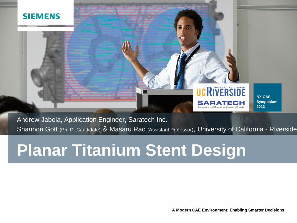
Agenda
Objective
Background: Motivation for Stenting
Planar Stent Challenges
FEA: The Key to Redesign
Post-processing
Comparison Against Physical Test Data
Lessons Learned
2
Objective
Develop and refine titanium micromachining
techniques to create nanopatterned titanium
stents
Solve current stent limitations with physical means
Hypothesis: rationally-designed surface
nanopatterning will enhance desired vascular
cell responses relative to uncontrolled surfaces
3
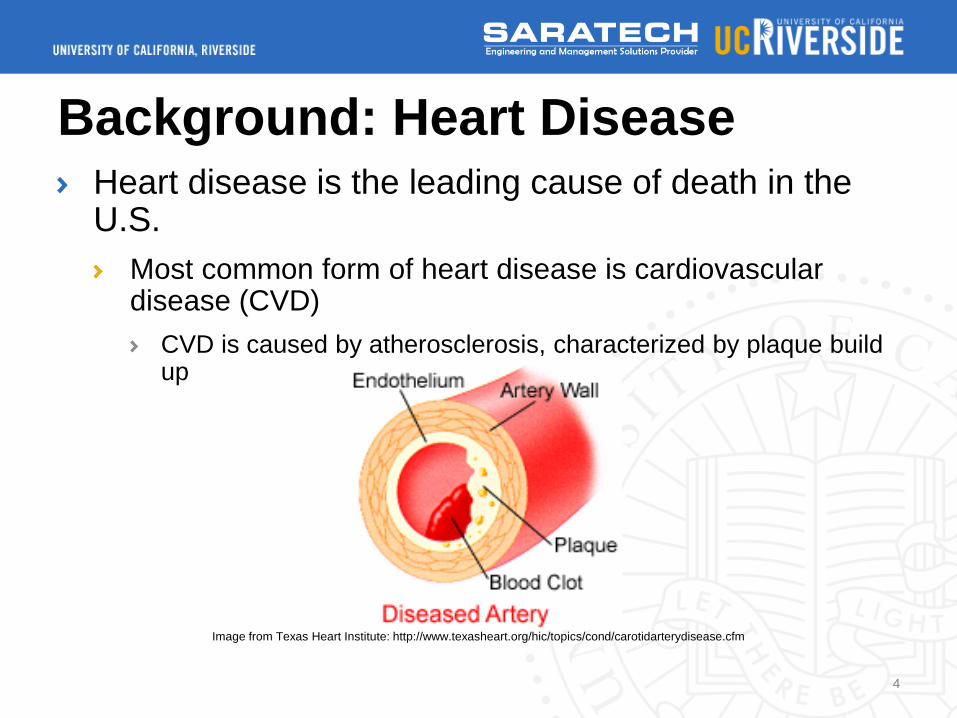
Background: Heart Disease Heart disease is the leading cause of death in the U.S.
Most common form of heart disease is cardiovascular disease (CVD)
CVD is caused by atherosclerosis, characterized by plaque build up
Image from Texas Heart Institute: http://www.texasheart.org/hic/topics/cond/carotidarterydisease.cfm
4
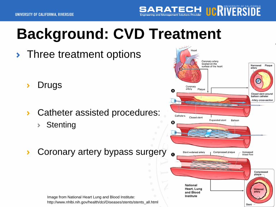
Background: CVD Treatment
Three treatment options
Drugs
Catheter assisted procedures:
Stenting
Coronary artery bypass surgery
Image from National Heart Lung and Blood Institute:
http://www.nhlbi.nih.gov/health/dci/Diseases/stents/stents_all.html
5
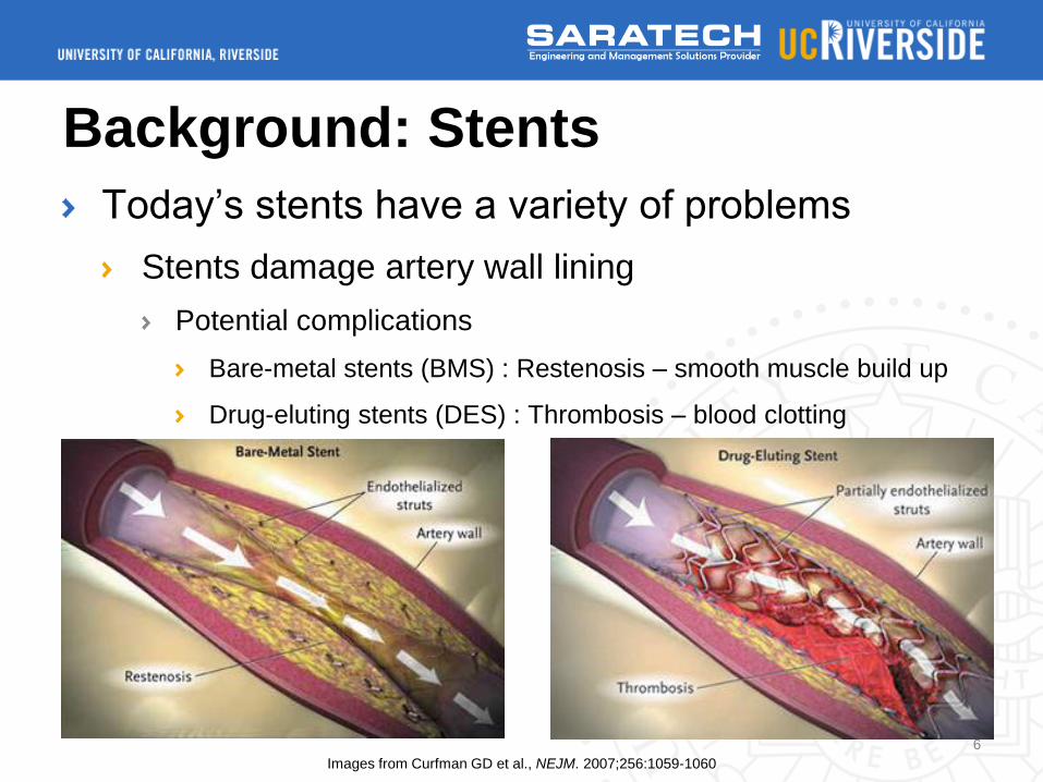
Background: Stents
Today’s stents have a variety of problems
Stents damage artery wall lining
Potential complications
Bare-metal stents (BMS) : Restenosis – smooth muscle build up
Drug-eluting stents (DES) : Thrombosis – blood clotting
Images from Curfman GD et al., NEJM. 2007;256:1059-1060
6
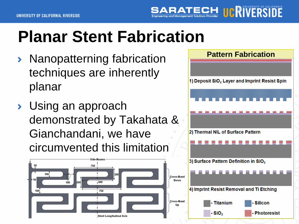
Planar Stent Fabrication
Nanopatterning fabrication
techniques are inherently
planar
Using an approach
demonstrated by Takahata &
Gianchandani, we have
circumvented this limitation
7
Pattern Fabrication
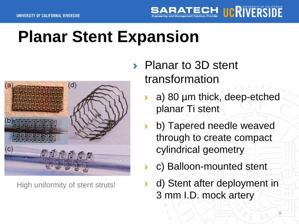
Planar Stent Expansion
Planar to 3D stent
transformation
a) 80 µm thick, deep-etched
planar Ti stent
b) Tapered needle weaved
through to create compact
cylindrical geometry
c) Balloon-mounted stent
d) Stent after deployment in
3 mm I.D. mock artery
8
High uniformity of stent struts!
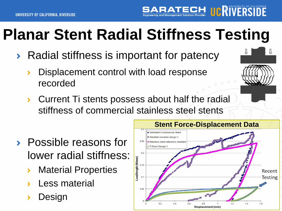
Planar Stent Radial Stiffness Testing
Radial stiffness is important for patency
Displacement control with load response
recorded
Current Ti stents possess about half the radial
stiffness of commercial stainless steel stents
Possible reasons for
lower radial stiffness:
Material Properties
Less material
Design 9
Stent Force-Displacement Data
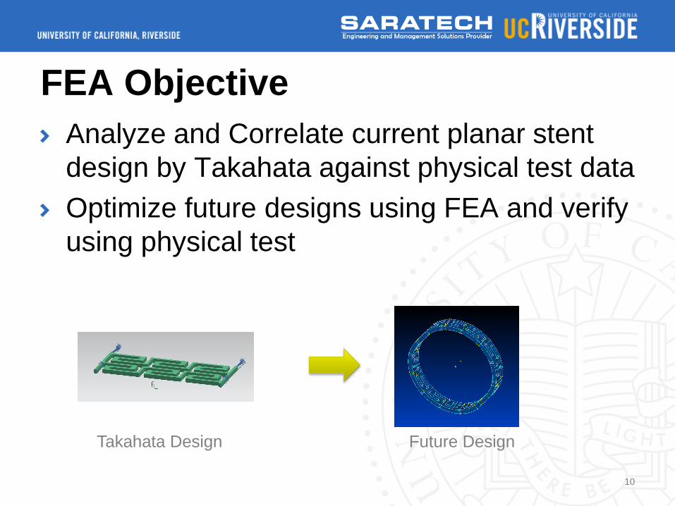
FEA Objective
Analyze and Correlate current planar stent
design by Takahata against physical test data
Optimize future designs using FEA and verify
using physical test
10
Takahata Design Future Design
Analysis Challenges
Highly Nonlinear Analysis
Large Displacement/Large Strain
Difficult Contact Analysis both in Expansion and
Crushing
Nonlinear Material Properties
11

Analysis Objective
Expand Stent to match deployed
configuration
Stent is expanded to 3 mm in diameter
Crush Stent to correlate against physical test
data
Stent is crushed back to 1.5 mm for correlation
12
Analysis Setup
Pre/Post – NX 8.5 – Advanced Simulation
Solver – NX NASTRAN 8.5 Advanced
Nonlinear (ADINA) 601/129 NL Transient
Solution
Solution Timesteps (time/time steps)
Expansion (100 s/410 time steps)
Expander Relax (25 s/50 time steps)
Crush (75 s/200 time steps)
13
Analysis Setup
Material – Grade 1 Commercial Pure
Titanium
Isotropic, Plastic, Setup with a NL Stress-Strain
Curve
Stress-Strain Curve determined through tensile testing
by UC Riverside
Isotropic Hardening
14

Analysis Setup
Stress-Strain Curve
Data points were reduced from actual test data
15
0
50
100
150
200
250
300
0 0.02 0.04 0.06 0.08 0.1 0.12 0.14
Str
ess (
MP
a)
Strain (mm/mm)
Titanium Stress-Strain Curve
Analysis Setup
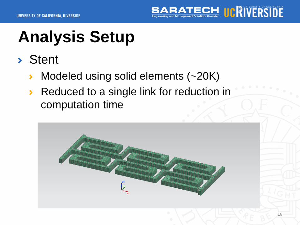
Stent
Modeled using solid elements (~20K)
Reduced to a single link for reduction in
computation time
16
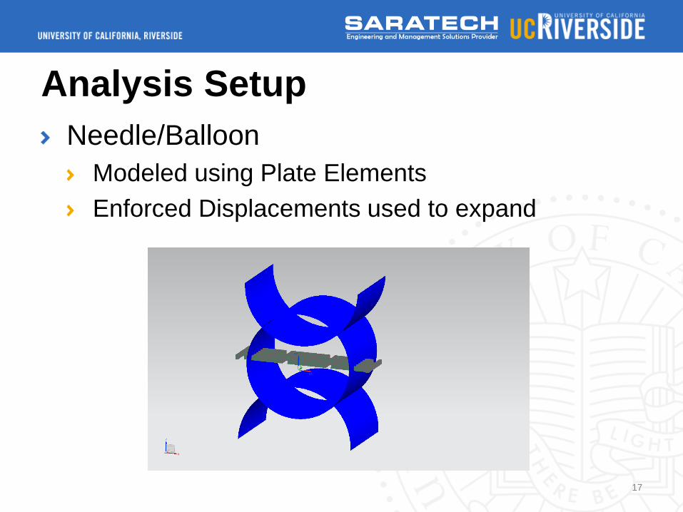
Analysis Setup
Needle/Balloon
Modeled using Plate Elements
Enforced Displacements used to expand
17
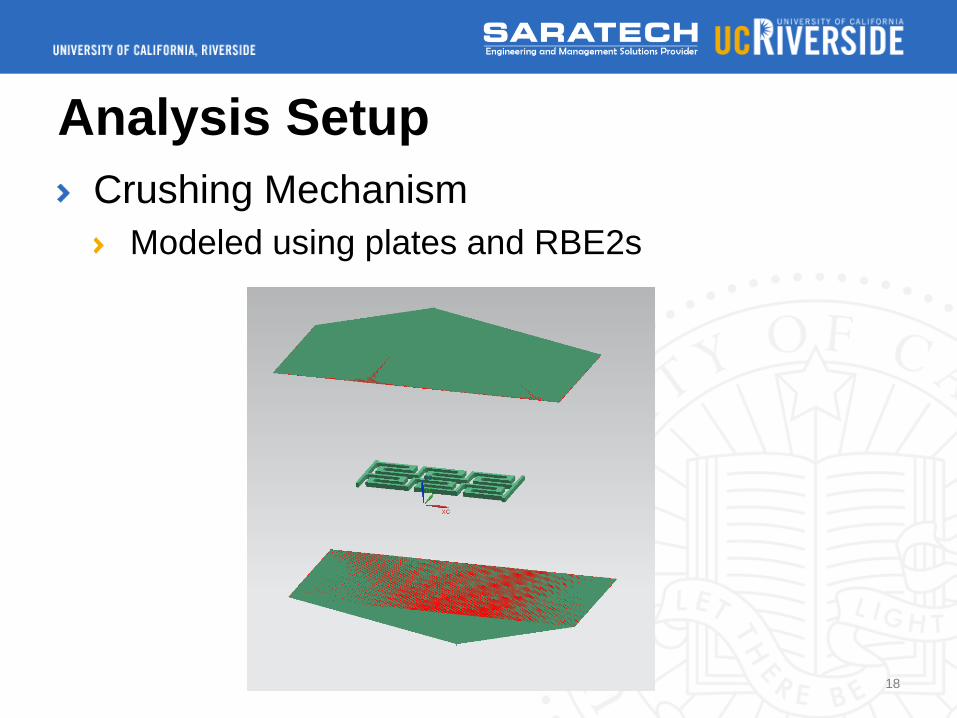
Analysis Setup
Crushing Mechanism
Modeled using plates and RBE2s
18
Analysis Setup
Elements
Overall Element size is 0.015 mm
Linear Solid (HEX/WEDGE) and Plate Elements
used
Plate Region is also the same resolution for
contact considerations
Element Count: 216732 elements
19
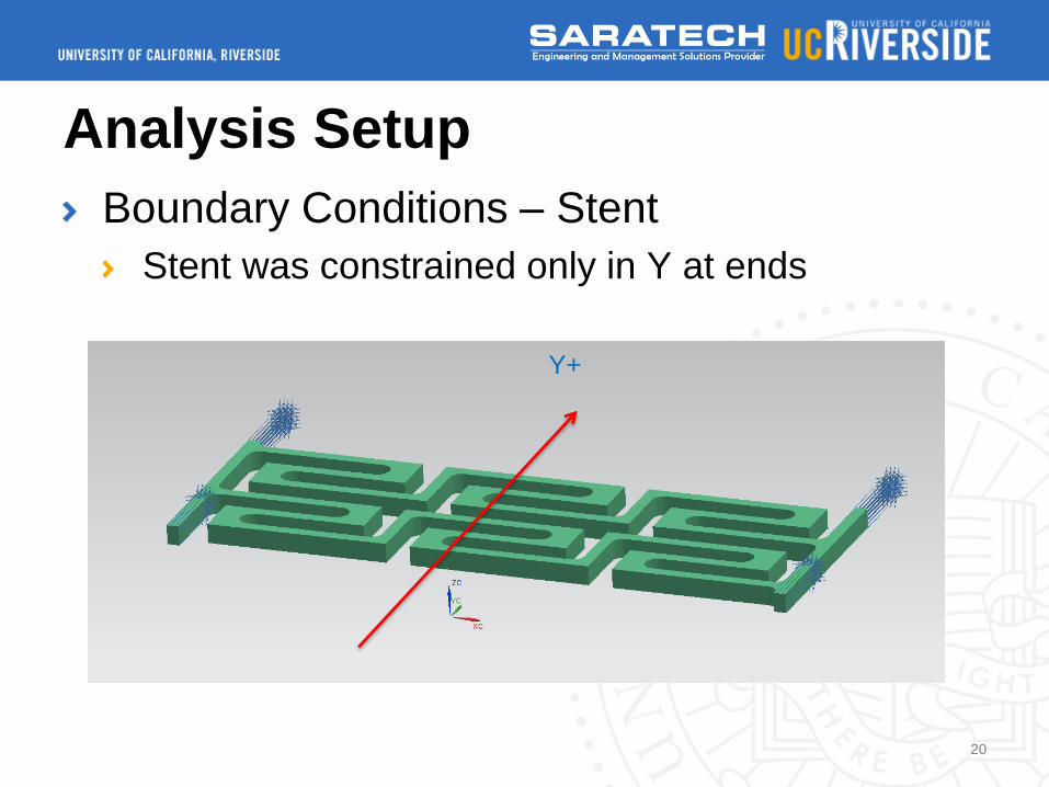
Analysis Setup
Boundary Conditions – Stent
Stent was constrained only in Y at ends
20
Y+
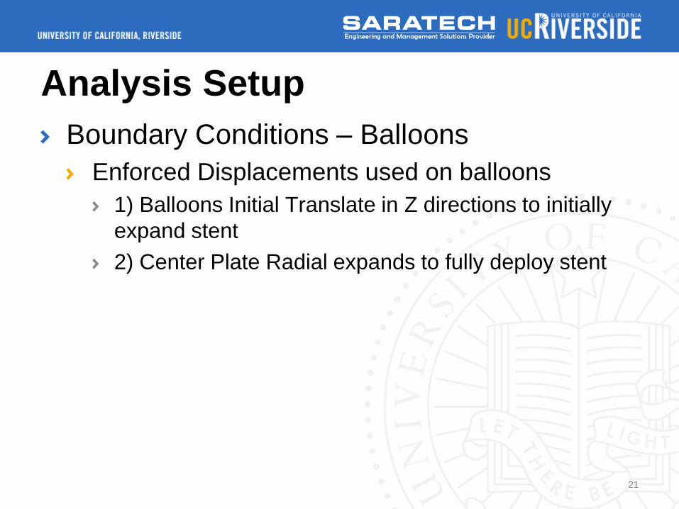
Analysis Setup
Boundary Conditions – Balloons
Enforced Displacements used on balloons
1) Balloons Initial Translate in Z directions to initially
expand stent
2) Center Plate Radial expands to fully deploy stent
21
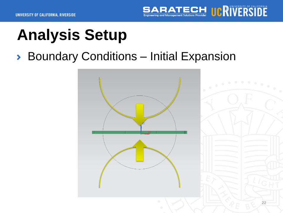
Analysis Setup
Boundary Conditions – Initial Expansion
22

Analysis Setup
Boundary Conditions – Full Deploy (3 mm)
23
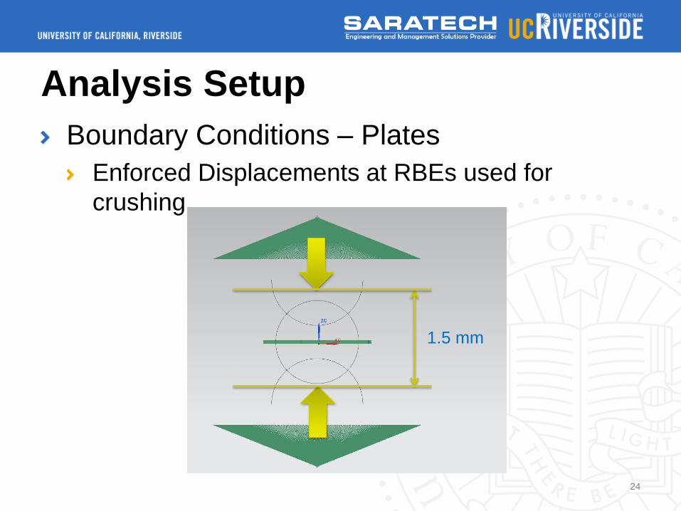
Analysis Setup
Boundary Conditions – Plates
Enforced Displacements at RBEs used for
crushing
24
1.5 mm
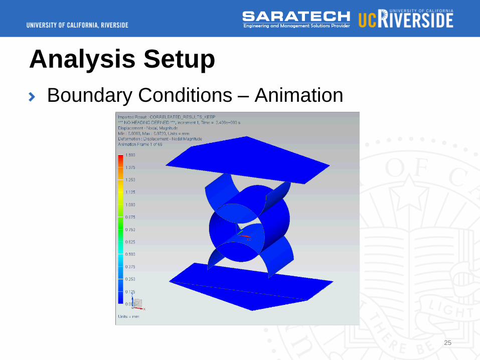
Analysis Setup
Boundary Conditions – Animation
25
Analysis Setup
Contact Conditions
Frictionless Contact
Contact Birth/Death Used for expansion and
crushing
26
Analysis
NX NASTRAN Adv. NL (ADINA) – 601/129
Transient Analysis
Solution Memory: 5.4 GB
27
Post-processing
Test Correlation Indicators
Visual Deformation
Crushing Reaction Force
28
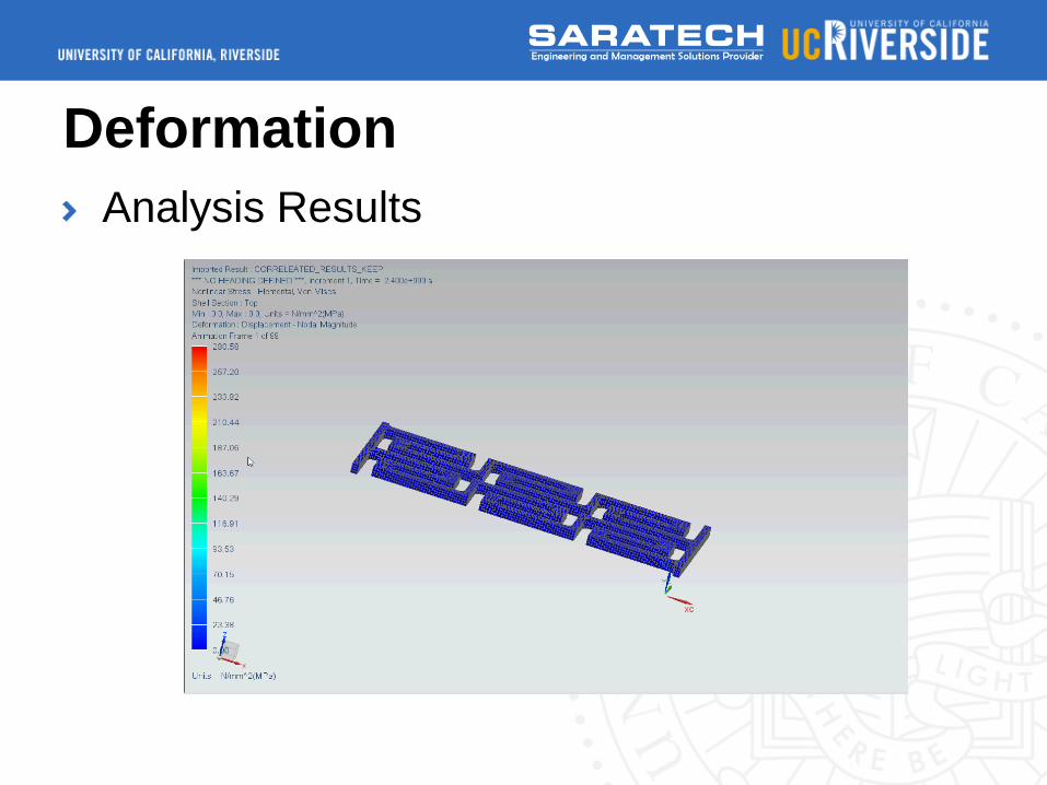
Deformation
Analysis Results
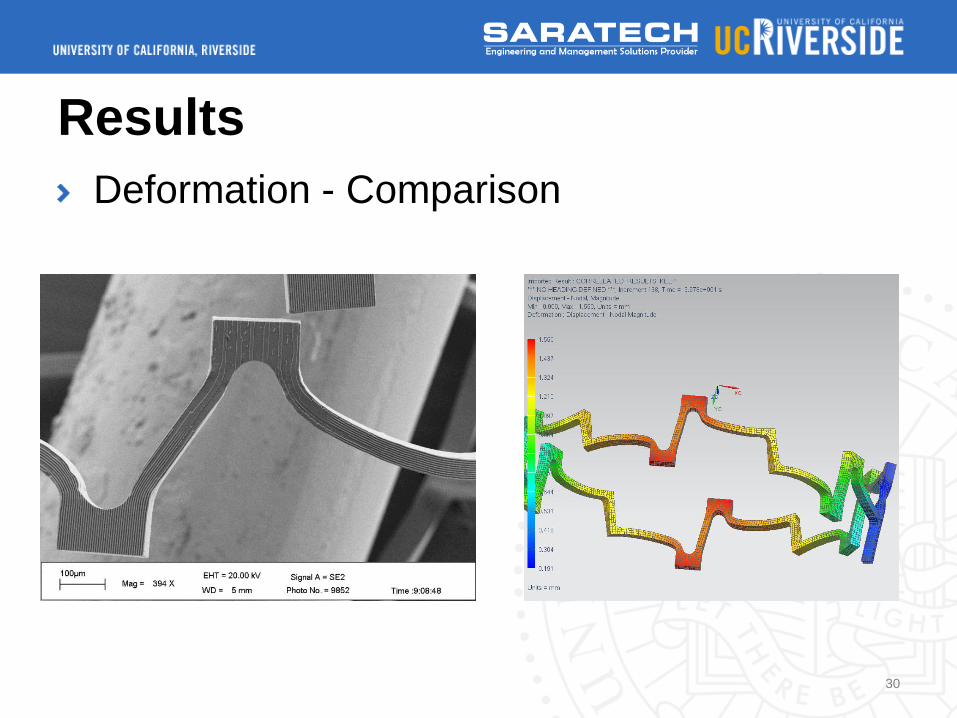
Results
Deformation - Comparison
30
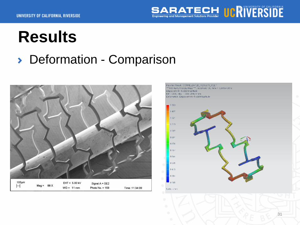
Results
Deformation - Comparison
31
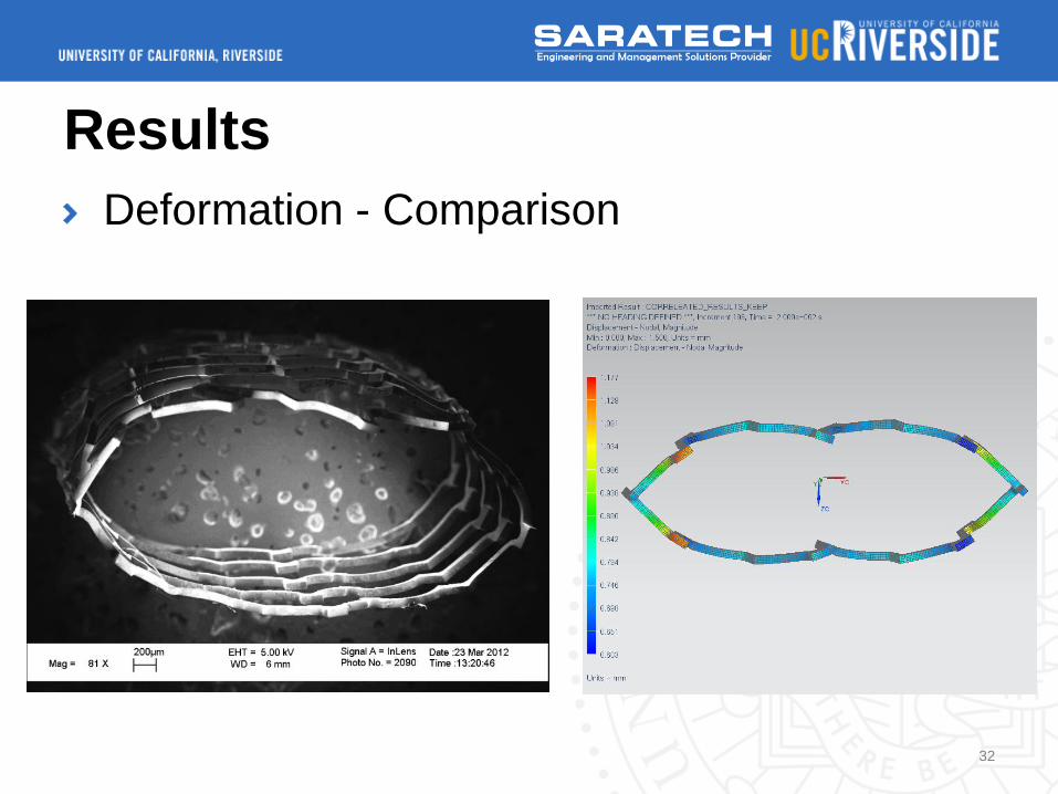
Results
Deformation - Comparison
32
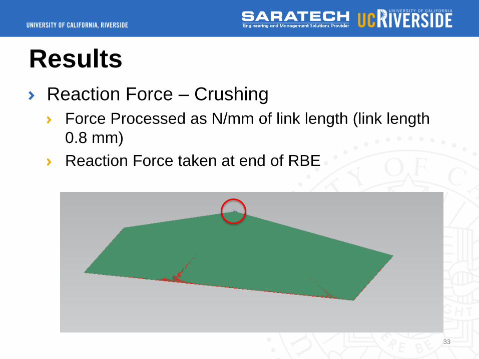
Results
Reaction Force – Crushing
Force Processed as N/mm of link length (link length
0.8 mm)
Reaction Force taken at end of RBE
33

Results
Reaction Force – FEA vs. Physical Test
34
Lessons Learned
Analysis was product of many runs
Following is list of important parameters and
lessons learned while running SOL 601/129
These can be applied to many other NL
analyses
35
Lessons Learned
General Tips
Step-by-Step – Analyze in pieces, don’t try and
setup entire analysis in one shot
Time Step Optimization – Place Time Steps only
where you need them
Automatic Time Stepping is a must (should be a
default)
36
Lessons Learned
Contact Parameters and Mesh Resolution
Line Search – Turn this on to help with contact
problems
Mesh Resolution – Meshes must match between
contact to get most accurate force results
Contact Damping is required, but needs to be
tuned, otherwise results can be odd
37
Future Work
Future Work is being carried on by Shannon
Gott of UC Riverside
Optimization of design to increase stiffness
Fatigue Life Analysis
38
Conclusion
Correlation between physical test data and
FEA was achieved using NX NASTRAN and
NX CAE
Many lessons learned that are applicable to
many nonlinear situations
Provides Basis for future work
39

Q/A
40

References 1. J. Lu, M. P. Rao, N. C. MacDonald, D. Khang and T. J. Webster,
Acta Biomaterialia, 2008, 4, 192-201.
2. P. Vandrangi, S. C. Gott, V. G. J. Rodgers and M. P. Rao,
presented in part at the 7th International Conference on
Microtechnologies in Medicine and Biology, Marina Del Rey, CA,
April 10 – 12, 2013, 2013.
3. A. W. Martinez and E. L. Chaikof, Wiley Interdiscip. Rev.-Nanomed.
Nanobiotechnol., 2011, 3, 256-268.
4. M. F. Aimi, M. P. Rao, N. C. Macdonald, A. S. Zuruzi and D. P.
Bothman, Nat. Mater., 2004, 3, 103-105.
5. E. R. Parker, B. J. Thibeault, M. F. Aimi, M. P. Rao and N. C.
MacDonald, J. Electrochem. Soc., 2005, 152, C675-C683.
6. K. Takahata and Y. B. Gianchandani, J. Microelectromech. Syst.,
2004, 13, 933-939.
41