UNIVERSITY OF CALIFORNIA, IRVINE · University of California, Irvine, 2009 Professor Lorenzo...
46
UNIVERSITY OF CALIFORNIA, IRVINE Mechanical Investigation of a Novel Bio-Mimetic Morphing Structure THESIS submitted in partial satisfaction of the requirements for the degree of MASTER OF SCIENCE In Materials Science and Engineering by Eva Maria Carreira Ramos Thesis Committee: Professor Lorenzo Valdevit, Chair Professor Daniel R. Mumm Professor Farghalli A. Mohamed 2009
Transcript of UNIVERSITY OF CALIFORNIA, IRVINE · University of California, Irvine, 2009 Professor Lorenzo...
UNIVERSITY OF CALIFORNIA,
IRVINE
Mechanical Investigation of a Novel Bio-Mimetic Morphing Structure
THESIS
submitted in partial satisfaction of the requirements
for the degree of
MASTER OF SCIENCE
In Materials Science and Engineering
by
Eva Maria Carreira Ramos
Thesis Committee:
Professor Lorenzo Valdevit, Chair
Professor Daniel R. Mumm
Professor Farghalli A. Mohamed
2009

© 2009 Eva Maria Carreira Ramos
ii
The thesis of Eva Maria Carreira Ramos is approved:
______________________________
______________________________
______________________________
Committee Chair
University of California, Irvine
2009
iii
TABLE OF CONTENTS
LIST OF FIGURES ........................................................................................................... iv
ACKNOWLEDGMENTS .................................................................................................. v
ABSTRACT OF THE THESIS ......................................................................................... vi
1. INTRODUCTION ....................................................................................................... 1
2. MORPHOLOGICAL FEATURES OF BATOID FISH ............................................. 3
3. SYNTHETIC MORPHING STRUCTURES .............................................................. 8
3.1 Corrugated-core Sandwich Beam ......................................................................... 8
3.2 Kagome-based Sandwich Plate .......................................................................... 12
3.3 Tensegrity-based Morphing Concepts ............................................................... 13
4. A novel biomimetic morphing concept: numerical study and prototype
demonstration .................................................................................................................... 15
4.1 The Finite Element Model .................................................................................. 18
5. CONCLUSIONS AND FUTURE WORK ................................................................ 35
6. BIBLIOGRAPHY ..................................................................................................... 36
iv
LIST OF FIGURES Figure 1. Batoid fish ........................................................................................................... 4
Figure 2. Schematic of cross-bracing. ................................................................................. 6
Figure 3. Cross bracing in oscillatory swimmers. ............................................................... 7
Figure 4. An optimal SMA actuator ................................................................................... 9
Figure 5. Cantilever sandwich beam with different core designs ..................................... 11
Figure 6. Hinging and twisting modes. ............................................................................. 13
Figure 7. Cross bracing and actual structure. .................................................................... 16
Figure 8. Mechanism ........................................................................................................ 16
Figure 9. Swimming-like motion ...................................................................................... 17
Figure 10. Boundary conditions ........................................................................................ 20
Figure 11. Motion of the model. ....................................................................................... 21
Figure 12. Plot 1 ................................................................................................................ 22
Figure 13. Plot 2 ................................................................................................................ 23
Figure 14. Plot 3. ............................................................................................................... 24
Figure 15. Maximum twisting produced in the motion of the wing. ................................ 25
Figure 16. Final of the bending phase. .............................................................................. 26
Figure 17. Final step of the simulation. ............................................................................ 27
Figure 18. Plot 4 ................................................................................................................ 28
Figure 19. Failure point for the called ‘J’ calculation. ...................................................... 29
Figure 20. Boundary conditions for the rotational simulation .......................................... 30
Figure 21. Failure step. ..................................................................................................... 31
Figure 22. Boundary conditions for the simulation actuated in three nodes. ................... 32
Figure 23. Plot 5 ................................................................................................................ 33
Figure 24. Plot 6 ................................................................................................................ 34
v
ACKNOWLEDGMENTS
I would like to express the deepest gratitude and appreciation to my committee chair,
Professor Lorenzo Valdevit for his guidance and persistent support.
I acknowledge the members of my committee: Professor Daniel Mumm and Professor
Farghalli A. Mohamed.
In addition, I would like to thank all the members in my group and Professor Roger
Rangel’s group for the good work environment created and especially, to Anna Torrents
who has always supported me.Gràcies Anna!
Finally, I would like to acknowledge the financial support from Balsells-Generalitat de
Catalunya fellowship 2007-2008.
vi
ABSTRACT OF THE THESIS
Mechanical Investigation of a Novel Bio-Mimetic Morphing Structure
By
Eva Maria Carreira Ramos
Master of Science in Materials Science and Engineering
University of California, Irvine, 2009
Professor Lorenzo Valdevit, Chair
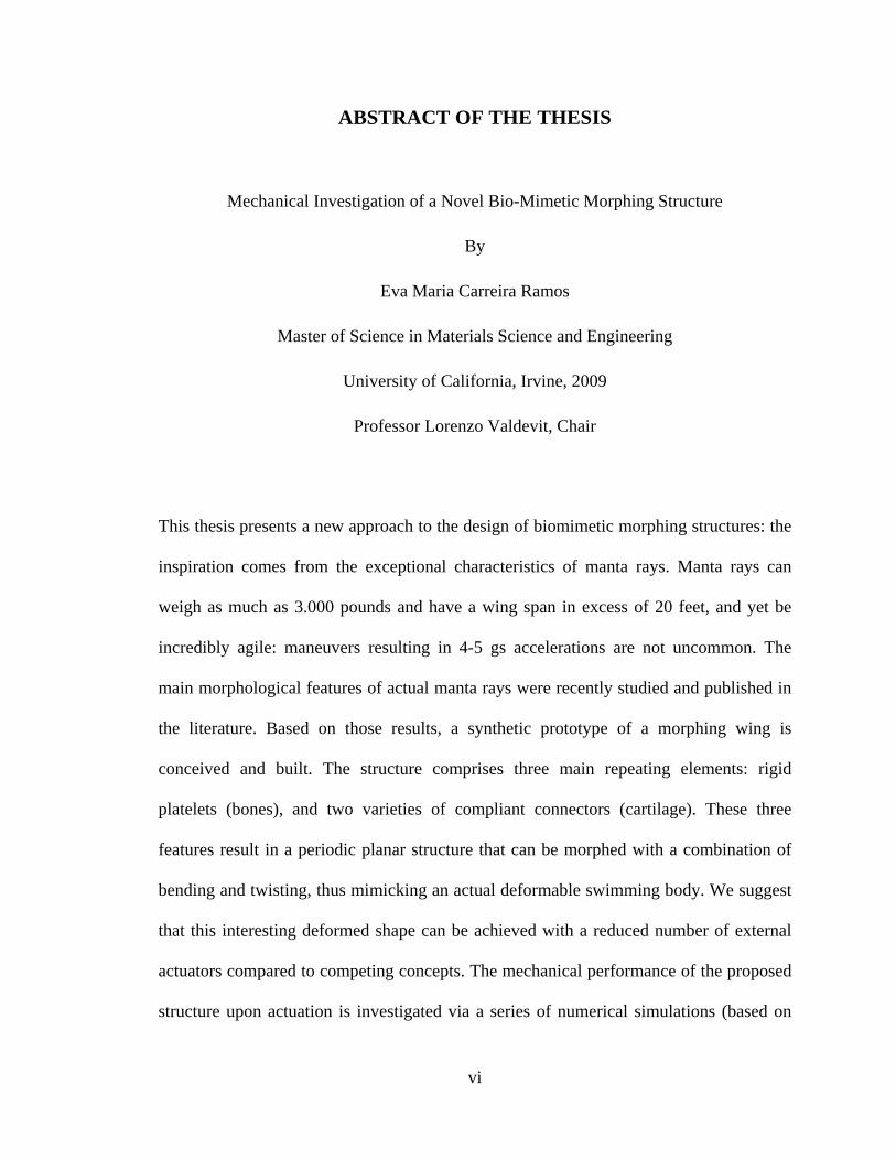
This thesis presents a new approach to the design of biomimetic morphing structures: the
inspiration comes from the exceptional characteristics of manta rays. Manta rays can
weigh as much as 3.000 pounds and have a wing span in excess of 20 feet, and yet be
incredibly agile: maneuvers resulting in 4-5 gs accelerations are not uncommon. The
main morphological features of actual manta rays were recently studied and published in
the literature. Based on those results, a synthetic prototype of a morphing wing is
conceived and built. The structure comprises three main repeating elements: rigid
platelets (bones), and two varieties of compliant connectors (cartilage). These three
features result in a periodic planar structure that can be morphed with a combination of
bending and twisting, thus mimicking an actual deformable swimming body. We suggest
that this interesting deformed shape can be achieved with a reduced number of external
actuators compared to competing concepts. The mechanical performance of the proposed
structure upon actuation is investigated via a series of numerical simulations (based on
vii
the commercial Finite Element package ABAQUS). Although extensive amount of work
in this project is still underway (mostly regarding manufacturability, actuation schemes
and durability), this work supports a novel approach for the design of high-authority
morphing structures.
1
1. INTRODUCTION
Nowadays, maneuverable underwater vehicles are affected by deficiencies due to the use
of traditional propulsive techniques, i.e. rotary motors and their related difficulty and
expensive repairs. Attempts to build faster and more efficient vehicles have been made in
the biomimetic morphing structures field.
The manta ray and other batoid fishes are an excellent inspiration for autonomous
underwater vehicles due to being extremely efficient swimmers, propulsing in some cases
as much as 5.000 lb of weight and 25 ft across length body. Moreover, they can cruise at
high speeds and can perform 4-5 gs acceleration when maneuvering. Due to all these
properties, the efforts have been focused in the design of a morphing plate with these
characteristics: low actuation energy, high authority, ability to morph into complex
shapes, and large stroke. Two different approaches have excelled in achieving many of
these characteristics: corrugated core sandwich beams and kagome based sandwich plates
[9-18]. One last approach is the use of tensegrity structures to mimic the locomotion of
these fishes [19-21].
In this paper, a different approach to the structural foundation of the bio-inspired
morphing wing is used, based on the last studies of the morphology of the actual manta
ray [1-8]. Radials are the basis of locomotion of batoid fish; a unit cell based on
interradial joints (cross-bracing) is detected in oscillatory swimmers [1]. A synthetic
prototype is conceived and built based on three main repeating elements: rigid platelets
(bones), and two varieties of compliant connectors (cartilage). These three features result
in a periodic planar structure that can be morphed with a combination of bending and
2
twisting so, mimicking an actual deformable swimming body. The mechanical
performance of such structure upon actuation is investigated through numerical
simulations (based on the commercial Finite Element package ABAQUS). Additionaly,
different types of connectors are studied to gain a better understanding of the kinematic
behavior of the morphing plate built and the deflections achieved are compared with
those found in the references.
3
2. MORPHOLOGICAL FEATURES OF BATOID FISH
The exceptional swimming performance of several families of fish (in particular batoid
fish) has motivated intense investigation into optimal design principles for bio-mimetic
morphing structures [9-21]. Mimicking the undulation of fish tails and wings has been the
focus of most of the activity in this area. Although some performance metrics of batoid
fish were demonstrated with synthetic structures [19, 21], the synthetic structure design is
based on standard mechanical engineering concepts (trusses, frames, tensegrity
structures). To the best of our knowledge, very few attempts have been made to identify
the morphological features that enable batoid fish’s phenomenal performance metrics and
reproduce them in a synthetic structure. This was partly due to the lack of information
about the morphology of these animals. A series of very careful biological and
biomechanical studies of various families of manta rays have been published [1-8]. Based
on these findings, our work focuses on mimicking the morphological features of the
propulsion mechanism used by the manta ray uses to swim long distances at high speeds.
The main morphological features of batoid fish are presented in [1].
The pectoral fins of batoid fishes (stingrays, skates, sawfishes and guitarfishes) are long
and fused to the cranium, forming in many cases large wing-like structures. These
pectoral fins are usually used as the primary locomotion propulsors [3-4].
The skeleton of these “wings” for skates and rays is formed by a series of radially
oriented cartilaginous fin rays whose origin is a modified pectoral girdle (the set of bones
that connect the axial skeleton on each side) shown in Figure 1. Those fin rays are a
4
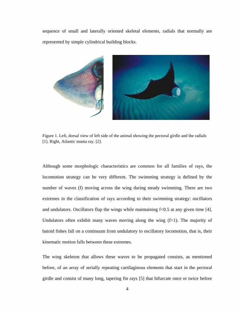
sequence of small and laterally oriented skeletal elements, radials that normally are
represented by simple cylindrical building blocks.
Figure 1. Left, dorsal view of left side of the animal showing the pectoral girdle and the radials [1]. Right, Atlantic manta ray. [2].
Although some morphologic characteristics are common for all families of rays, the
locomotion strategy can be very different. The swimming strategy is defined by the
number of waves (f) moving across the wing during steady swimming. There are two
extremes in the classification of rays according to their swimming strategy: oscillators
and undulators. Oscillators flap the wings while maintaining f<0.5 at any given time [4].
Undulators often exhibit many waves moving along the wing (f>1). The majority of
batoid fishes fall on a continuum from undulatory to oscillatory locomotion, that is, their
kinematic motion falls between these extremes.
The wing skeleton that allows these waves to be propagated consists, as mentioned
before, of an array of serially repeating cartilaginous elements that start in the pectoral
girdle and consist of many long, tapering fin rays [5] that bifurcate once or twice before
5
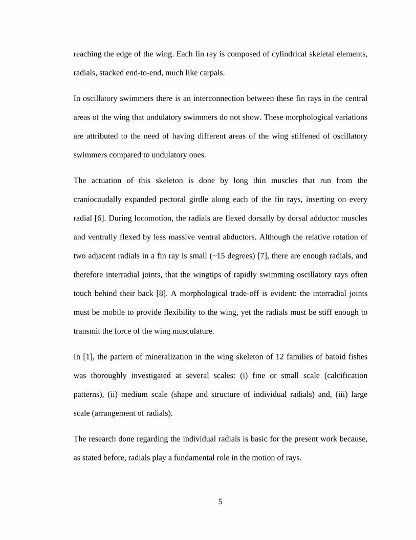
reaching the edge of the wing. Each fin ray is composed of cylindrical skeletal elements,
radials, stacked end-to-end, much like carpals.
In oscillatory swimmers there is an interconnection between these fin rays in the central
areas of the wing that undulatory swimmers do not show. These morphological variations
are attributed to the need of having different areas of the wing stiffened of oscillatory
swimmers compared to undulatory ones.
The actuation of this skeleton is done by long thin muscles that run from the
craniocaudally expanded pectoral girdle along each of the fin rays, inserting on every
radial [6]. During locomotion, the radials are flexed dorsally by dorsal adductor muscles
and ventrally flexed by less massive ventral abductors. Although the relative rotation of
two adjacent radials in a fin ray is small (~15 degrees) [7], there are enough radials, and
therefore interradial joints, that the wingtips of rapidly swimming oscillatory rays often
touch behind their back [8]. A morphological trade-off is evident: the interradial joints
must be mobile to provide flexibility to the wing, yet the radials must be stiff enough to
transmit the force of the wing musculature.
In [1], the pattern of mineralization in the wing skeleton of 12 families of batoid fishes
was thoroughly investigated at several scales: (i) fine or small scale (calcification
patterns), (ii) medium scale (shape and structure of individual radials) and, (iii) large
scale (arrangement of radials).
The research done regarding the individual radials is basic for the present work because,
as stated before, radials play a fundamental role in the motion of rays.

6
For all the families studied, the cross-section of radials varies within and among the
species and this cross-sectional shape changes with position on the wing depending on
the individuals. In addition, some species exhibit interradial connections –cross-braces;
each cross brace connects two radials in adjacent fin rays in some areas of the wing
(Figure 2). Cross-bracing is observed in medial areas of the wing of semi-oscillatory and
oscillatory swimmers (Figure 3) occupying, in some cases, the major part of the wing.
Figure 2. Schematic of cross-bracing. Fin ray “A” is joined to fin ray “B” by a cartilaginous extension (CB). This inhibits the bending of normal radial joints j1 and j2. Radial A1 will bend when the joint between radials B1 and B2 tries to bend. J2 loses the ability to bend in this motion. These cross-braces are arranged in diagonal patterns such that the entire area is reinforced and stiffened. [1]
7
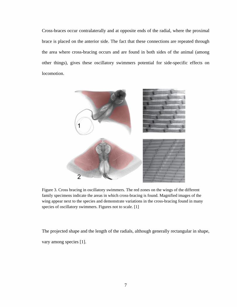
Cross-braces occur contralaterally and at opposite ends of the radial, where the proximal
brace is placed on the anterior side. The fact that these connections are repeated through
the area where cross-bracing occurs and are found in both sides of the animal (among
other things), gives these oscillatory swimmers potential for side-specific effects on
locomotion.
Figure 3. Cross bracing in oscillatory swimmers. The red zones on the wings of the different family specimens indicate the areas in which cross-bracing is found. Magnified images of the wing appear next to the species and demonstrate variations in the cross-bracing found in many species of oscillatory swimmers. Figures not to scale. [1]
The projected shape and the length of the radials, although generally rectangular in shape,
vary among species [1].
8
Mimicking locomotion of oscillatory swimmers following the cross-bracing pattern
(Figure 2) in a synthetic planar structure, could present advantages compared to
competing concepts presented in the next chapter.
3. SYNTHETIC MORPHING STRUCTURES
The approaches to build fast, efficient, and maneuverable underwater vehicles have
looked to nature for inspiration.
Traditional propulsive techniques have been based on rotary motors. The disadvantages
of these methods are the imperfect sealing, low efficiency, low engine life and difficult
repairs when needed.
Several attempts have been made to overcome the limitations of the traditional propulsion
methods [9-21].
The unifying theme has been the quest to design a morphing plate (or shell) with the
following characteristics: (i) low actuation energy; (ii) high-authority (i.e. the ability to
actuate against restraining loads); (iii) ability to morph into complex shapes; (iv) large
stroke. Two structures that excel in (i-iii) are the corrugated-core sandwich beam (in 1D)
[9-17] and the kagome-based sandwich plate (in 3D) [18].
3.1 Corrugated-core Sandwich Beam
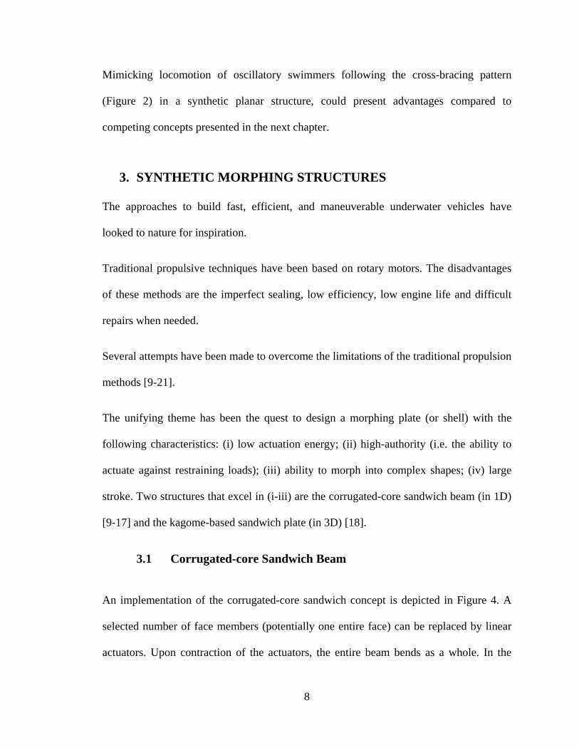
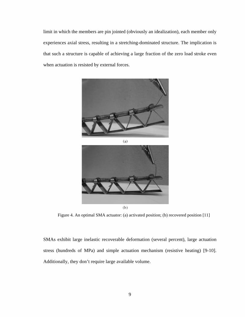
An implementation of the corrugated-core sandwich concept is depicted in Figure 4. A
selected number of face members (potentially one entire face) can be replaced by linear
actuators. Upon contraction of the actuators, the entire beam bends as a whole. In the
9
limit in which the members are pin jointed (obviously an idealization), each member only
experiences axial stress, resulting in a stretching-dominated structure. The implication is
that such a structure is capable of achieving a large fraction of the zero load stroke even
when actuation is resisted by external forces.
Figure 4. An optimal SMA actuator: (a) activated position; (b) recovered position [11]
SMAs exhibit large inelastic recoverable deformation (several percent), large actuation
stress (hundreds of MPa) and simple actuation mechanism (resistive heating) [9-10].
Additionally, they don’t require large available volume.
10
Pre-stretched, one-way SMA linear actuators contract upon heating above a critical
(austenite start) temperature. However, in the absence of an applied tensile load, these
actuators do not ‘re-stretch’ upon cooling [10]. The design of a two-way morphing
structure with a one-way SMA actuator requires some ingenuity. One solution envisions
the insertion of elastic springs in parallel with the morphing elements (Figure 4). Upon
cooling, the SMA transforms back to its martensitic phase (characterized by a low yield
strength) and is permanently stretched to its initial configuration by the action of the
springs. An alternative solution combines two corrugated core sandwiches, joined by a
passive (shear resistant) face sheet and each with the active face on the outside [13-16].
When one active face is heated up, it will contract yielding the opposite face (martensitic)
in tension. Upon cooling of the first face (and its transformation to martensitic phase),
and heating of the second active face, this latter face will contract and stretch the first
face in tension. This cyclic behavior results in two-way operation. The design was later
improved modifying the core topology and the shape memory pre-strain [14]. Lastly, the
core has been replaced with a structure that used freely rotating, revolute joints between
the unit cells [15], which reduced the elastic energy stored in the core. Each of these
devices consisted of a series of linearly repeating antagonistic flexural unit cells (AFC)
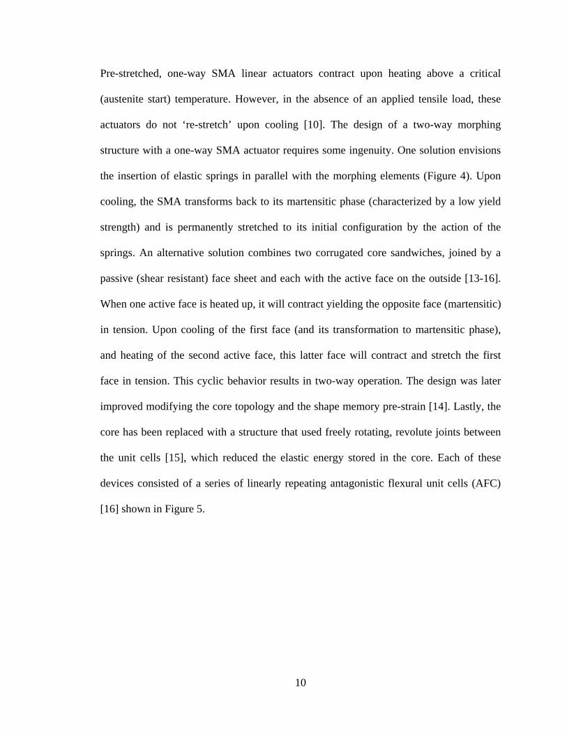
[16] shown in Figure 5.
11
Figure 5. (a) A cantilever sandwich beam constructed from a triangular corrugated core and pre-strained shape memory alloy face sheets. Heating one side causes contraction of that face sheet, and consequent tensile elongation of the non-heated face sheet, and an overall flexural deformation of the beam and (b) alternative design in which the core facilitates bending between the adjacent unit cells via rotation joints (vertebra) [16].
It should be briefly mentioned that two-way SMAs do exist, but they require extensive
training and their performance (particularly in fatigue) is not nearly as desirable relative
to one-way SMAs.
The corrugated-core structure enables actuation in one direction only. If more complex
shapes are desired (e.g. combined twisting and bending), 3D concepts need to be
explored.
12
3.2 Kagome-based Sandwich Plate
Guest and Hutchinson showed that no infinite truss can be simultaneously statically
determinate and stiff [17]. An exception exists for finite structures: it consists of two truss
face sheets with a kagome pattern (a combination of hexagons and triangles) sandwiched
by a tetrahedral truss core. One truss face can be replaced by a thin stiffness-matched
continuous face without excessive detriment in the properties. Such a structure was built
and bending and twisting motion with high-authority performance successfully
demonstrated [18].
The design consisted of an active back-plane comprising a Kagome truss, capable of
changing the shape of a solid face, connected to the back plane by means of a tetrahedral
truss core shown in Figure 6 [19]. A version of the structure was manufactured using
stainless steel active face and core, with a polycarbonate passive face, and commercially
available linear stepper actuators. Simple stepping motors were used as actuators
(replacing some back-face truss members). It was shown that, while the structure is
capable of sustaining large passive loads at low weight, the system is actuator-limited.
13
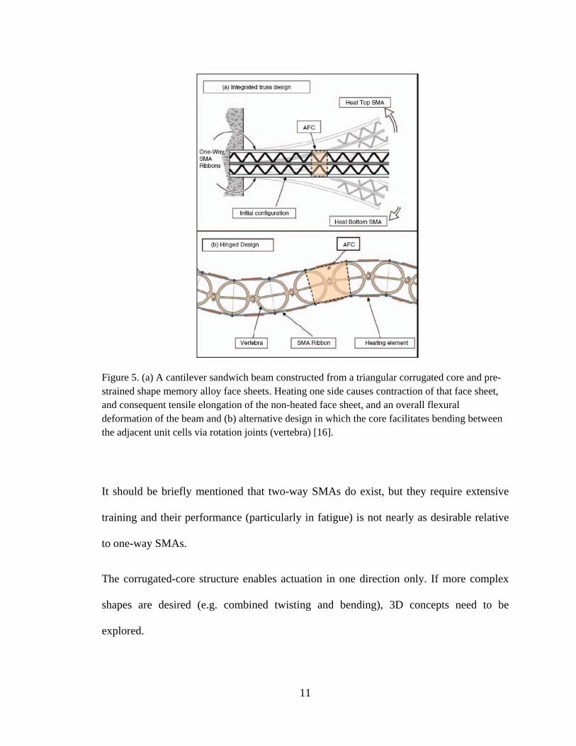
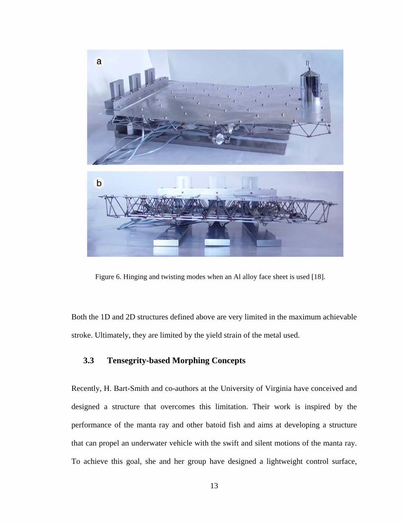
Figure 6. Hinging and twisting modes when an Al alloy face sheet is used [18].
Both the 1D and 2D structures defined above are very limited in the maximum achievable
stroke. Ultimately, they are limited by the yield strain of the metal used.
3.3 Tensegrity-based Morphing Concepts
Recently, H. Bart-Smith and co-authors at the University of Virginia have conceived and
designed a structure that overcomes this limitation. Their work is inspired by the
performance of the manta ray and other batoid fish and aims at developing a structure
that can propel an underwater vehicle with the swift and silent motions of the manta ray.
To achieve this goal, she and her group have designed a lightweight control surface,
14
manipulated by an active tensegrity structure, with high out-of plane stiffness and a large
range of motion under large restraining moments [20, 22].
Tensegrity structures are comprised of a set of discontinuous compressed struts held
together with a continuous web of tensioned cables [21]. They offer high strength to mass
ratios, low mechanical wear in dynamical applications, and high deformability with
minimal input energy, which makes these systems excellent candidates for the structural
layout of a morphing wing. In [20], the wing is actuated by replacing passive cables and
struts with actuators.
The location and selected motion of each actuator was optimized with the goal of
achieving a displacement field as close as possible to that of a cownose ray (no data were
available for the manta ray).
Such a structure enables complex actuation shapes and previously unattainable
displacements and rotations. On the other hand, robustness is a concern (breakage of one
link in the structure can be disastrous). We also notice that tensegrity structures are
substantially different from the morphology of a ray. Although they meet a bio-mimetic
objective, they do not constitute a bio-mimetic design.
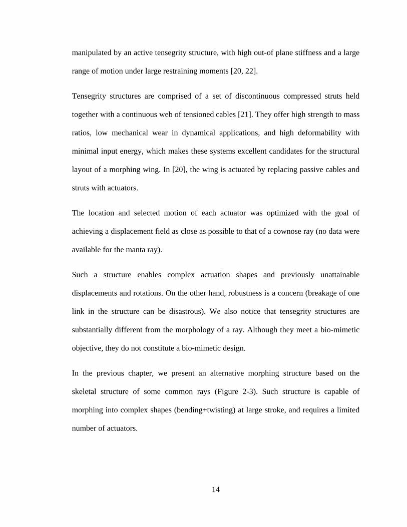
In the previous chapter, we present an alternative morphing structure based on the
skeletal structure of some common rays (Figure 2-3). Such structure is capable of
morphing into complex shapes (bending+twisting) at large stroke, and requires a limited
number of actuators.
15
4. A novel biomimetic morphing concept: numerical study and
prototype demonstration
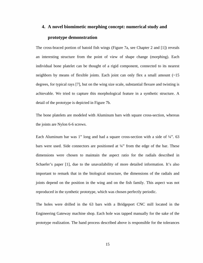
The cross-braced portion of batoid fish wings (Figure 7a, see Chapter 2 and [1]) reveals
an interesting structure from the point of view of shape change (morphing). Each
individual bone platelet can be thought of a rigid component, connected to its nearest
neighbors by means of flexible joints. Each joint can only flex a small amount (~15
degrees, for typical rays [7], but on the wing size scale, substantial flexure and twisting is
achievable. We tried to capture this morphological feature in a synthetic structure. A
detail of the prototype is depicted in Figure 7b.
The bone platelets are modeled with Aluminum bars with square cross-section, whereas
the joints are Nylon 6-6 screws.
Each Aluminum bar was 1” long and had a square cross-section with a side of ¼”. 63
bars were used. Side connectors are positioned at ¼” from the edge of the bar. These
dimensions were chosen to maintain the aspect ratio for the radials described in
Schaefer’s paper [1], due to the unavailability of more detailed information. It’s also
important to remark that in the biological structure, the dimensions of the radials and
joints depend on the position in the wing and on the fish family. This aspect was not
reproduced in the synthetic prototype, which was chosen perfectly periodic.
The holes were drilled in the 63 bars with a Bridgeport CNC mill located in the
Engineering Gateway machine shop. Each hole was tapped manually for the sake of the
prototype realization. The hand process described above is responsible for the tolerances
16
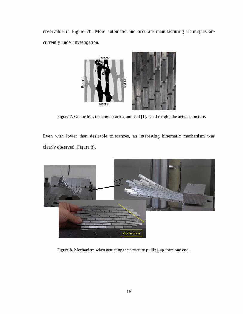
observable in Figure 7b. More automatic and accurate manufacturing techniques are
currently under investigation.
Figure 7. On the left, the cross bracing unit cell [1]. On the right, the actual structure.
Even with lower than desirable tolerances, an interesting kinematic mechanism was
clearly observed (Figure 8).
Figure 8. Mechanism when actuating the structure pulling up from one end.
17
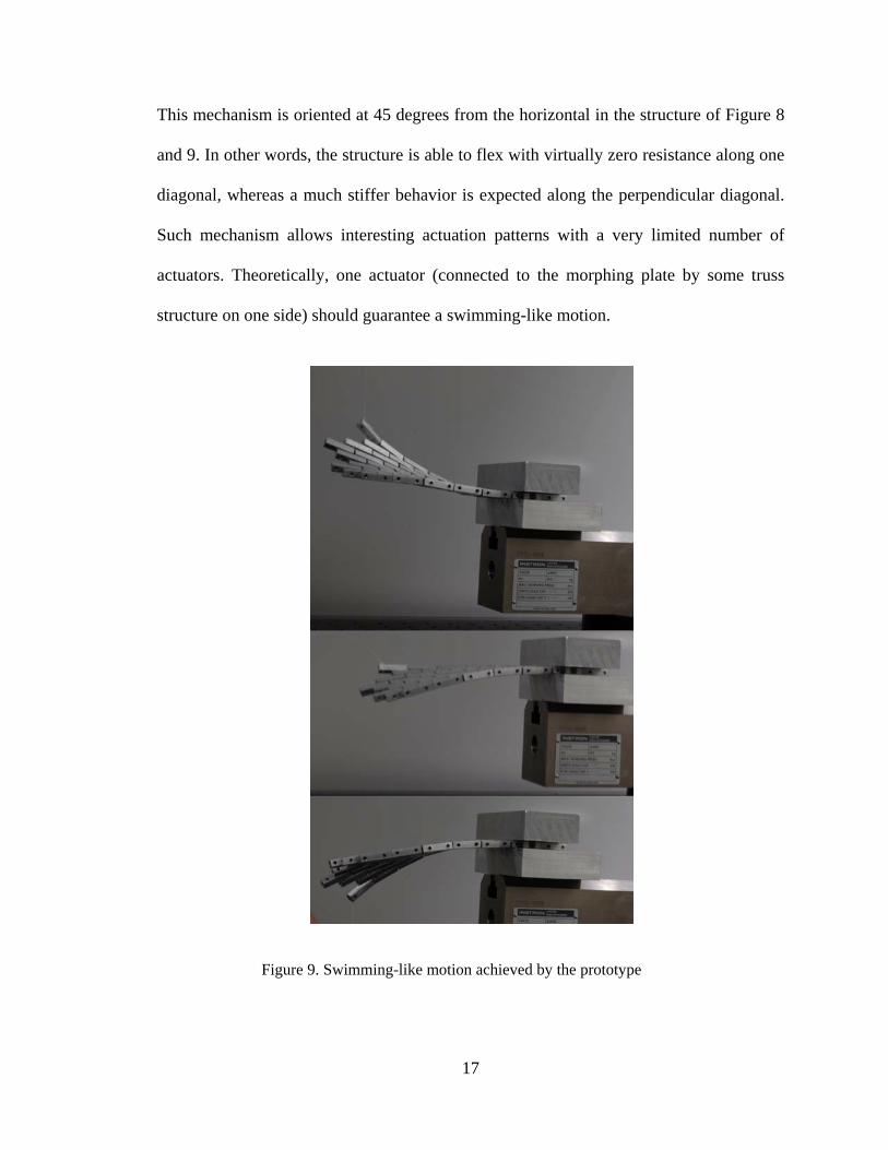
This mechanism is oriented at 45 degrees from the horizontal in the structure of Figure 8
and 9. In other words, the structure is able to flex with virtually zero resistance along one
diagonal, whereas a much stiffer behavior is expected along the perpendicular diagonal.
Such mechanism allows interesting actuation patterns with a very limited number of
actuators. Theoretically, one actuator (connected to the morphing plate by some truss
structure on one side) should guarantee a swimming-like motion.
Figure 9. Swimming-like motion achieved by the prototype
18
This contrasts with the competing concepts presented in Chapter 3, for which several
actuators are typically necessary to achieve interesting combinations of bending and
twisting [18-20, 22].
In order to demonstrate the mechanical behavior of this morphing structure, a Finite
Element model was built and simulated with the commercial code ABAQUS ©.
4.1 The Finite Element Model
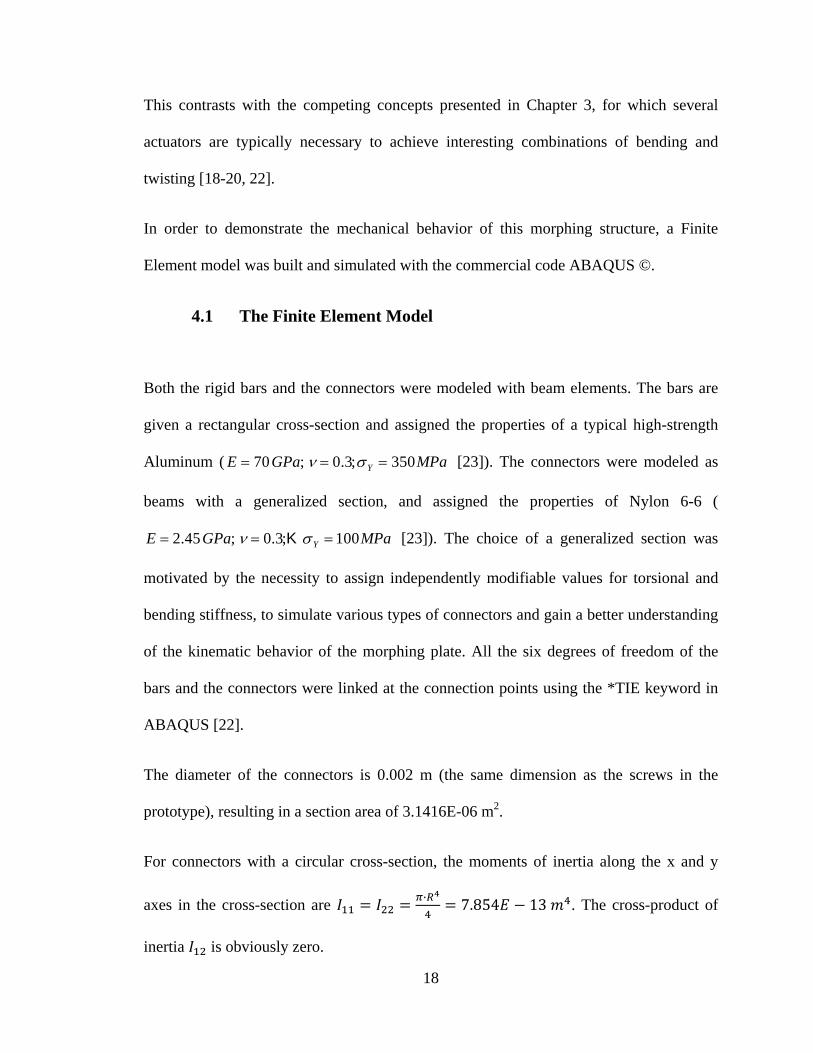
Both the rigid bars and the connectors were modeled with beam elements. The bars are
given a rectangular cross-section and assigned the properties of a typical high-strength
Aluminum ( E = 70GPa; ν = 0.3;σ Y = 350MPa [23]). The connectors were modeled as
beams with a generalized section, and assigned the properties of Nylon 6-6 (
E = 2.45GPa; ν = 0.3;K σ Y = 100MPa [23]). The choice of a generalized section was
motivated by the necessity to assign independently modifiable values for torsional and
bending stiffness, to simulate various types of connectors and gain a better understanding
of the kinematic behavior of the morphing plate. All the six degrees of freedom of the
bars and the connectors were linked at the connection points using the *TIE keyword in
ABAQUS [22].
The diameter of the connectors is 0.002 m (the same dimension as the screws in the
prototype), resulting in a section area of 3.1416E-06 m2.
For connectors with a circular cross-section, the moments of inertia along the x and y
axes in the cross-section are · 7.854 13 . The cross-product of
inertia is obviously zero.
19
For a solid circular beam, the torsional modulus J is given by: · ·
In the prototype (or in a real system), the degree of torsional constraint at the node is not
necessarily well represented by that corresponding to two welded beams. For example, in
the case of the prototype (where screws are used to secure mechanical joining of bars and
connectors), the screws offer substantial bending stiffness but virtually no torsional
stiffness at the connections (if friction on the threads is neglected). To study the effect of
the ratio of bending to torsional stiffness of the connectors –on the results, we ran two
sets of simulations: (i) one in which the connectors are simply circular section beams
welded to the bars (resulting in a torsional modulus of J (i ) =1.5708 ⋅10-12 m4 , and (ii)
one in which the torsional modulus is decreased by a factor 100 relative to case (i)
(resulting in J (ii ) = J (i ) 100 =1.5708 ⋅10-14 m4 ).
Sectorial moment of the section (Gamma O) and warping constants are assumed to be
equal to zero.
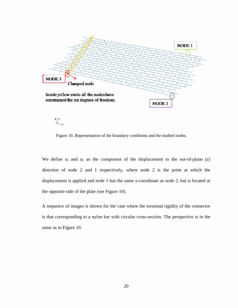
All six degrees of freedom were constrained for the nodes shown in Figure 10. A
displacement of 0.4 m was applied to the node marked in purple (Node 2).
20
Figure 10. Representation of the boundary conditions and the studied nodes.
We define u2 and u1 as the component of the displacement in the out-of-plane (z)
direction of node 2 and 1 respectively, where node 2 is the point at which the
displacement is applied and node 1 has the same x-coordinate as node 2, but is located at
the opposite side of the plate (see Figure 10).
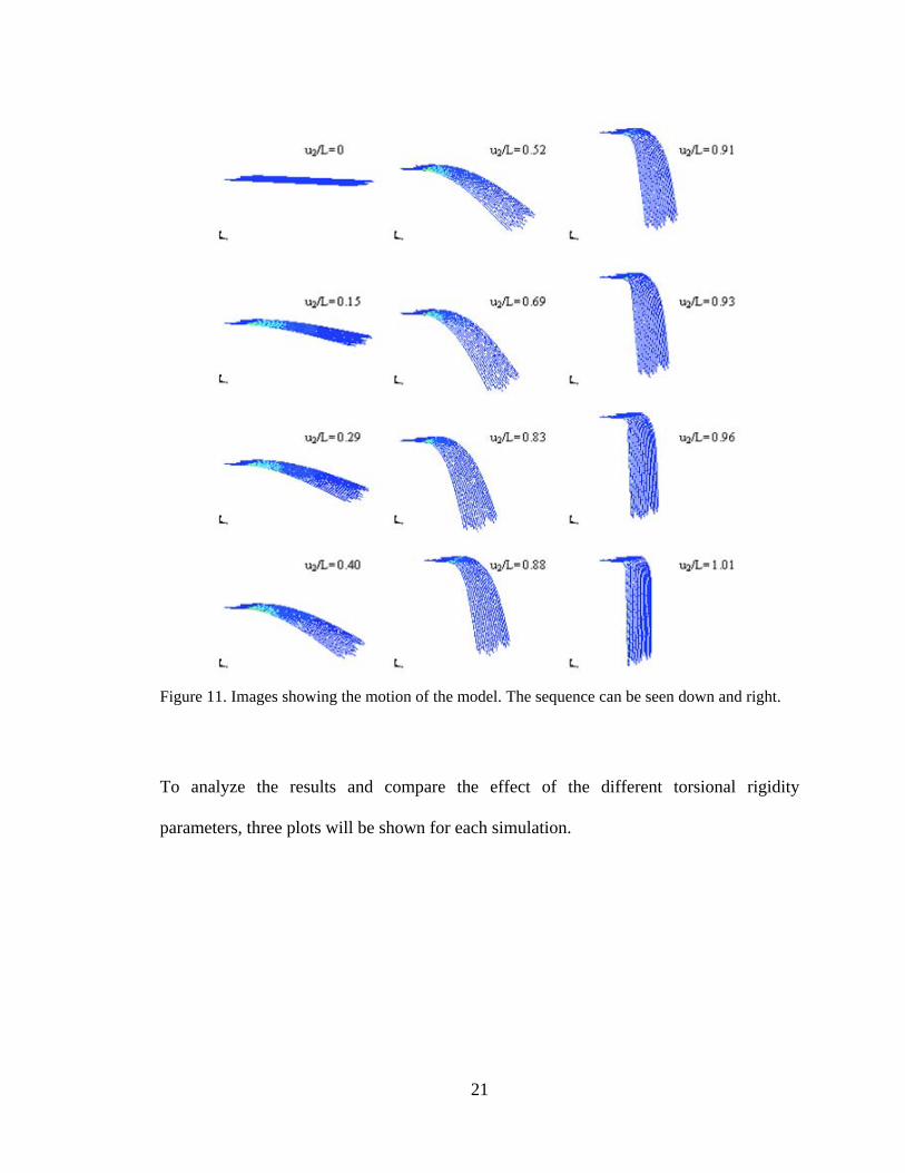
A sequence of images is shown for the case where the torsional rigidity of the connector
is that corresponding to a nylon bar with circular cross-section. The perspective is in the
same as in Figure 10.
21
Figure 11. Images showing the motion of the model. The sequence can be seen down and right.
To analyze the results and compare the effect of the different torsional rigidity
parameters, three plots will be shown for each simulation.
22
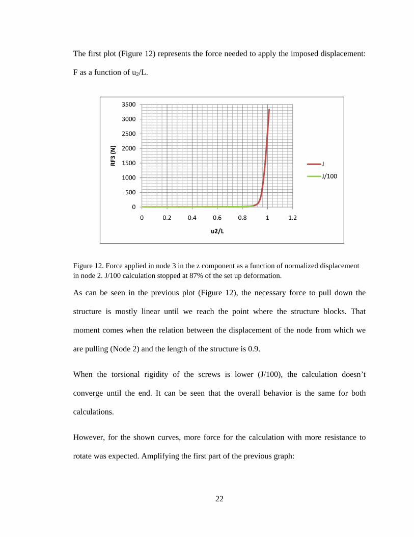
The first plot (Figure 12) represents the force needed to apply the imposed displacement:
F as a function of u2/L.
Figure 12. Force applied in node 3 in the z component as a function of normalized displacement in node 2. J/100 calculation stopped at 87% of the set up deformation.
As can be seen in the previous plot (Figure 12), the necessary force to pull down the
structure is mostly linear until we reach the point where the structure blocks. That
moment comes when the relation between the displacement of the node from which we
are pulling (Node 2) and the length of the structure is 0.9.
When the torsional rigidity of the screws is lower (J/100), the calculation doesn’t
converge until the end. It can be seen that the overall behavior is the same for both
calculations.
However, for the shown curves, more force for the calculation with more resistance to
rotate was expected. Amplifying the first part of the previous graph:
0
500
1000
1500
2000
2500
3000
3500
0 0.2 0.4 0.6 0.8 1 1.2
RF3 (N)
u2/L
J
J/100
23
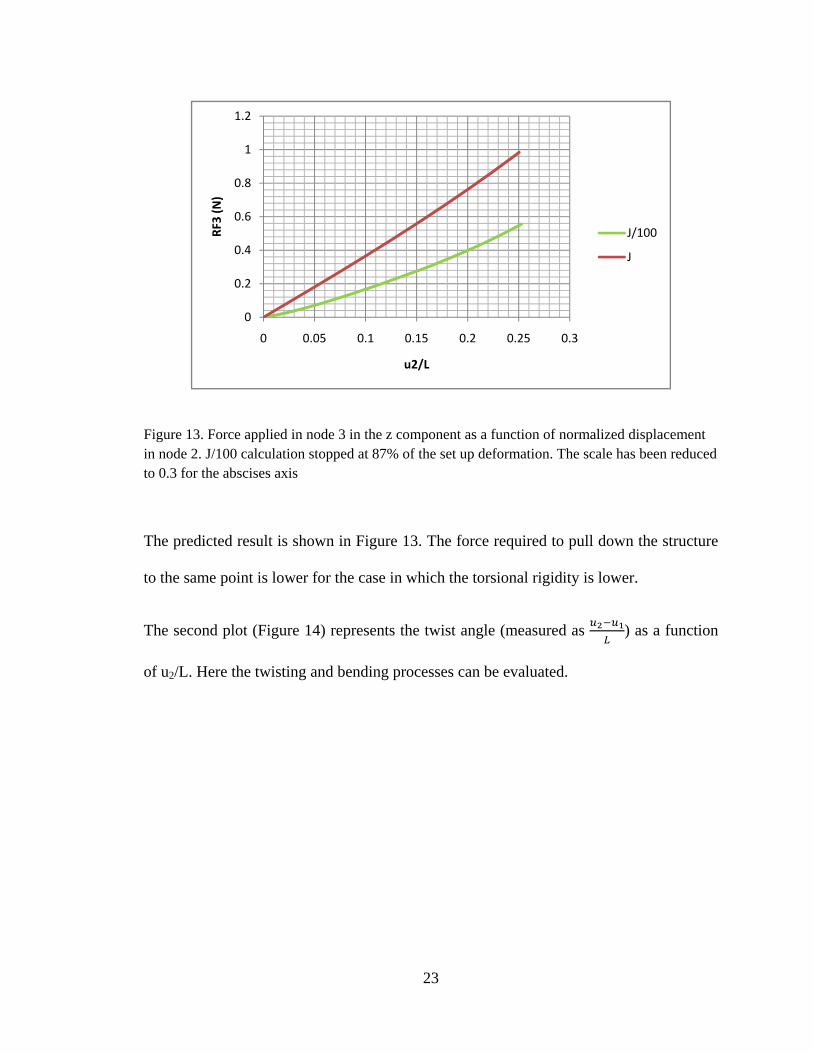
Figure 13. Force applied in node 3 in the z component as a function of normalized displacement in node 2. J/100 calculation stopped at 87% of the set up deformation. The scale has been reduced to 0.3 for the abscises axis
The predicted result is shown in Figure 13. The force required to pull down the structure
to the same point is lower for the case in which the torsional rigidity is lower.
The second plot (Figure 14) represents the twist angle (measured as ) as a function
of u2/L. Here the twisting and bending processes can be evaluated.
0
0.2
0.4
0.6
0.8
1
1.2
0 0.05 0.1 0.15 0.2 0.25 0.3
RF3 (N)
u2/L
J/100
J
24
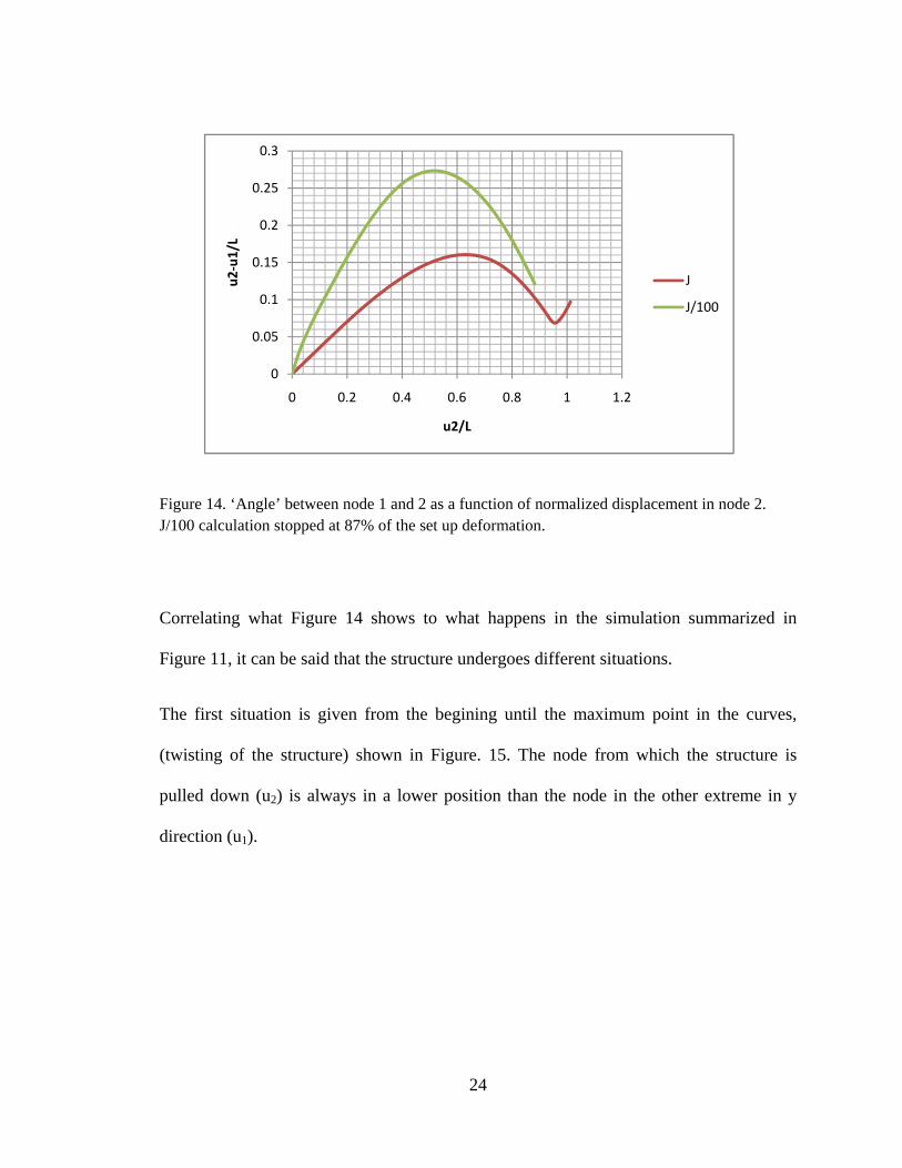
Figure 14. ‘Angle’ between node 1 and 2 as a function of normalized displacement in node 2. J/100 calculation stopped at 87% of the set up deformation.
Correlating what Figure 14 shows to what happens in the simulation summarized in
Figure 11, it can be said that the structure undergoes different situations.
The first situation is given from the begining until the maximum point in the curves,
(twisting of the structure) shown in Figure. 15. The node from which the structure is
pulled down (u2) is always in a lower position than the node in the other extreme in y
direction (u1).
0
0.05
0.1
0.15
0.2
0.25
0.3
0 0.2 0.4 0.6 0.8 1 1.2
u2‐u1/L
u2/L
J
J/100
25
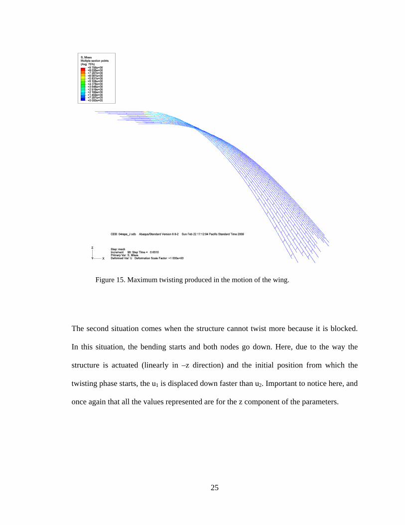
Figure 15. Maximum twisting produced in the motion of the wing.
The second situation comes when the structure cannot twist more because it is blocked.
In this situation, the bending starts and both nodes go down. Here, due to the way the
structure is actuated (linearly in –z direction) and the initial position from which the
twisting phase starts, the u1 is displaced down faster than u2. Important to notice here, and
once again that all the values represented are for the z component of the parameters.
26
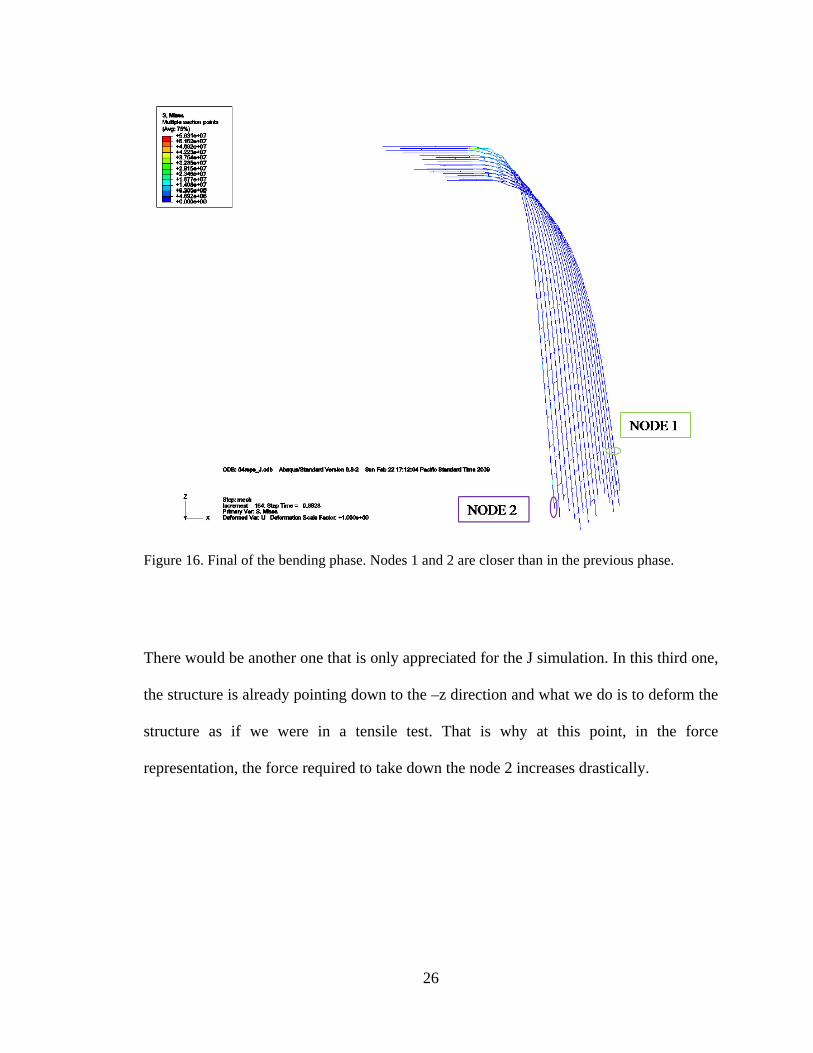
Figure 16. Final of the bending phase. Nodes 1 and 2 are closer than in the previous phase.
There would be another one that is only appreciated for the J simulation. In this third one,
the structure is already pointing down to the –z direction and what we do is to deform the
structure as if we were in a tensile test. That is why at this point, in the force
representation, the force required to take down the node 2 increases drastically.
27
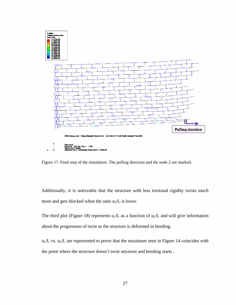
Figure 17. Final step of the simulation. The pulling direction and the node 2 are marked.
Additionally, it is noticeable that the structure with less torsional rigidity twists much
more and gets blocked when the ratio u2/L is lower.
The third plot (Figure 18) represents u1/L as a function of u2/L and will give information
about the progression of twist as the structure is deformed in bending.
u1/L vs. u2/L are represented to prove that the maximum seen in Figure 14 coincides with
the point where the structure doesn’t twist anymore and bending starts .
28
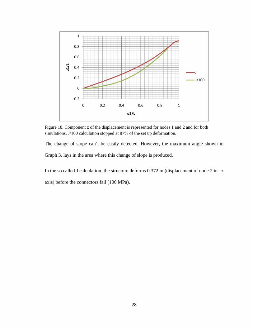
Figure 18. Component z of the displacement is represented for nodes 1 and 2 and for both simulations. J/100 calculation stopped at 87% of the set up deformation.
The change of slope can’t be easily detected. However, the maximum angle shown in
Graph 3. lays in the area where this change of slope is produced.
In the so called J calculation, the structure deforms 0.372 m (displacement of node 2 in –z
axis) before the connectors fail (100 MPa).
‐0.2
0
0.2
0.4
0.6
0.8
1
0 0.2 0.4 0.6 0.8 1
u1/L
u2/L
J
J/100
29
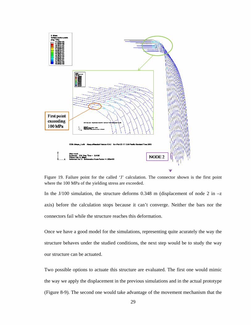
Figure 19. Failure point for the called ‘J’ calculation. The connector shown is the first point where the 100 MPa of the yielding stress are exceeded.
In the J/100 simulation, the structure deforms 0.348 m (displacement of node 2 in –z
axis) before the calculation stops because it can’t converge. Neither the bars nor the
connectors fail while the structure reaches this deformation.
Once we have a good model for the simulations, representing quite acurately the way the
structure behaves under the studied conditions, the next step would be to study the way
our structure can be actuated.
Two possible options to actuate this structure are evaluated. The first one would mimic
the way we apply the displacement in the previous simulations and in the actual prototype
(Figure 8-9). The second one would take advantage of the movement mechanism that the
30
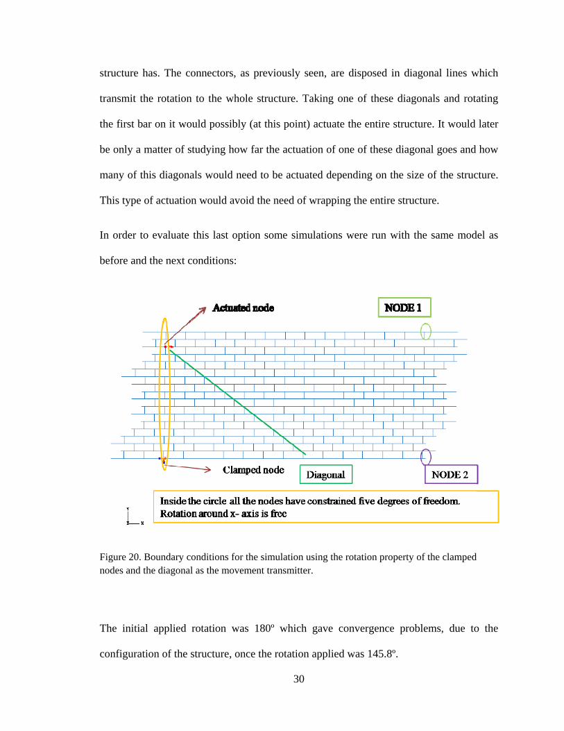
structure has. The connectors, as previously seen, are disposed in diagonal lines which
transmit the rotation to the whole structure. Taking one of these diagonals and rotating
the first bar on it would possibly (at this point) actuate the entire structure. It would later
be only a matter of studying how far the actuation of one of these diagonal goes and how
many of this diagonals would need to be actuated depending on the size of the structure.
This type of actuation would avoid the need of wrapping the entire structure.
In order to evaluate this last option some simulations were run with the same model as
before and the next conditions:
Figure 20. Boundary conditions for the simulation using the rotation property of the clamped nodes and the diagonal as the movement transmitter.
The initial applied rotation was 180º which gave convergence problems, due to the
configuration of the structure, once the rotation applied was 145.8º.
31
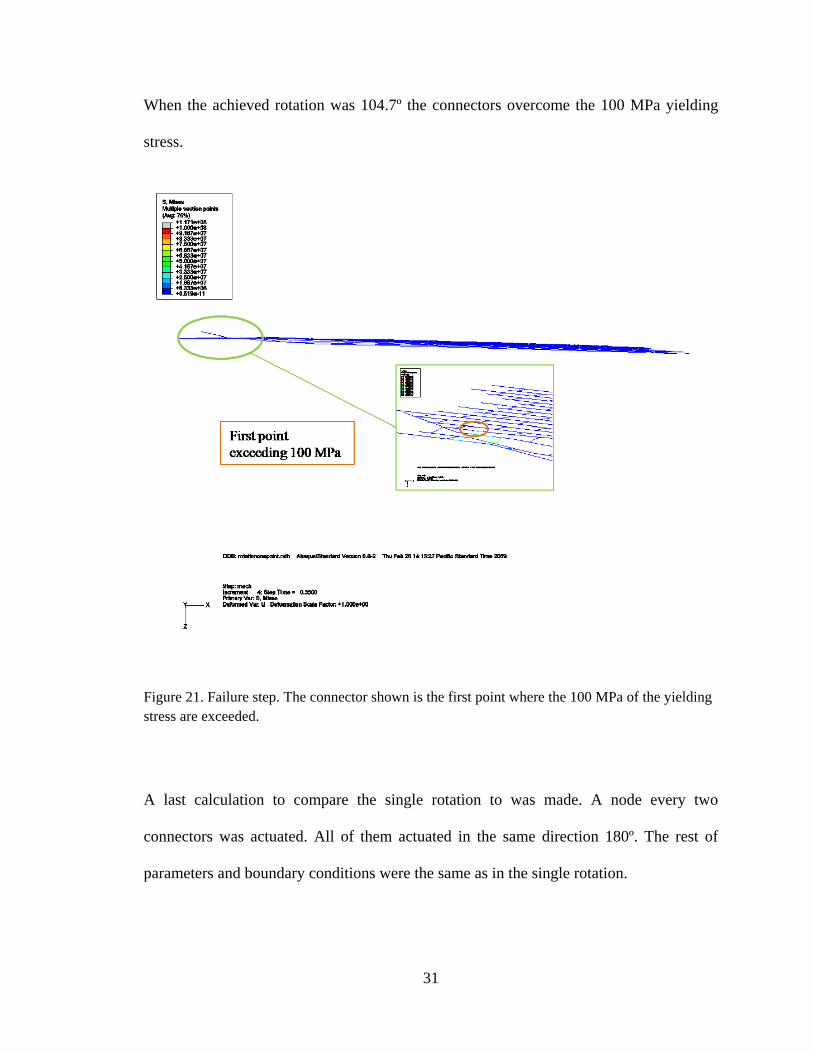
When the achieved rotation was 104.7º the connectors overcome the 100 MPa yielding
stress.
Figure 21. Failure step. The connector shown is the first point where the 100 MPa of the yielding stress are exceeded.
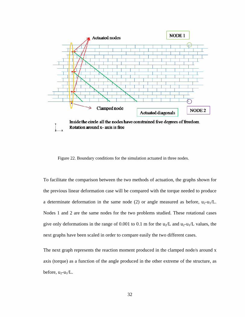
A last calculation to compare the single rotation to was made. A node every two
connectors was actuated. All of them actuated in the same direction 180º. The rest of
parameters and boundary conditions were the same as in the single rotation.
32
Figure 22. Boundary conditions for the simulation actuated in three nodes.
To facilitate the comparison between the two methods of actuation, the graphs shown for
the previous linear deformation case will be compared with the torque needed to produce
a determinate deformation in the same node (2) or angle measured as before, u2-u1/L.
Nodes 1 and 2 are the same nodes for the two problems studied. These rotational cases
give only deformations in the range of 0.001 to 0.1 m for the u2/L and u2-u1/L values, the
next graphs have been scaled in order to compare easily the two different cases.
The next graph represents the reaction moment produced in the clamped node/s around x
axis (torque) as a function of the angle produced in the other extreme of the structure, as
before, u2-u1/L.
33
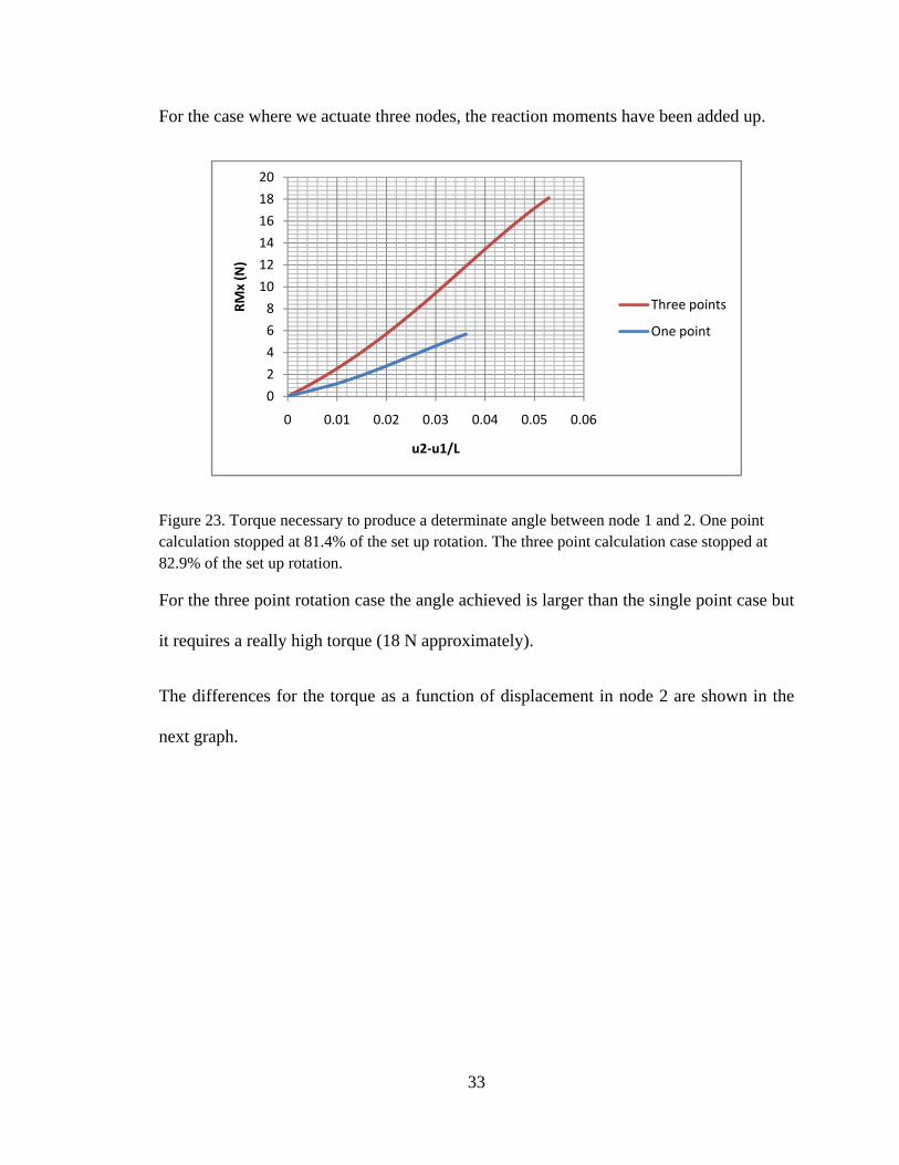
For the case where we actuate three nodes, the reaction moments have been added up.
Figure 23. Torque necessary to produce a determinate angle between node 1 and 2. One point calculation stopped at 81.4% of the set up rotation. The three point calculation case stopped at 82.9% of the set up rotation.
For the three point rotation case the angle achieved is larger than the single point case but
it requires a really high torque (18 N approximately).
The differences for the torque as a function of displacement in node 2 are shown in the
next graph.
0
2
4
6
8
10
12
14
16
18
20
0 0.01 0.02 0.03 0.04 0.05 0.06
RMx (N)
u2‐u1/L
Three points
One point
34
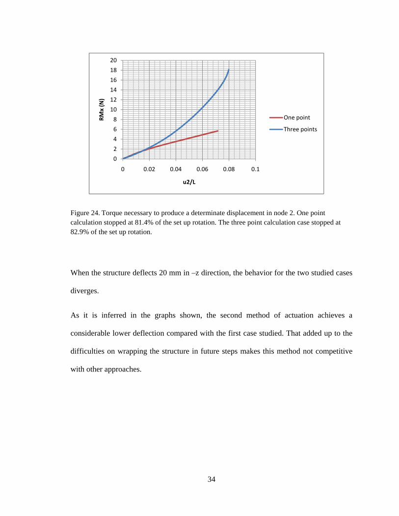
Figure 24. Torque necessary to produce a determinate displacement in node 2. One point calculation stopped at 81.4% of the set up rotation. The three point calculation case stopped at 82.9% of the set up rotation.
When the structure deflects 20 mm in –z direction, the behavior for the two studied cases
diverges.
As it is inferred in the graphs shown, the second method of actuation achieves a
considerable lower deflection compared with the first case studied. That added up to the
difficulties on wrapping the structure in future steps makes this method not competitive
with other approaches.
0
2
4
6
8
10
12
14
16
18
20
0 0.02 0.04 0.06 0.08 0.1
RMx (N)
u2/L
One point
Three points
35
5. CONCLUSIONS AND FUTURE WORK
A new synthetic structure that mimics an actual deformable swimming body has been
built, based on the actual morphology of oscillatory swimmers. A mechanism hidden in
the structure has been shown. Such mechanism allows interesting actuation patterns with
a very limited number of actuators contrasting with the presented competing concepts. A
model that represents the structure has been tested through different numerical
simulations based on the commercial Finite Element package ABAQUS. Different types
of connectors have been studied to gain a better understanding of the kinematic behavior
of the morphing plate built.
Finally, the deflections achieved are in good agreement with those achieved through
different approaches (ie. Tensegrity structures) presented in this work.
Therefore, it is concluded that this work supports a novel approach for the design of a
high-authority morphing structure although an extensive amount of work needs to be
done in the future to study its full capabilities. Further research is suggested regarding to
scaling of the structure, the actuation of the structure, actuation schemes and durability
and manufacturability.
36
6. BIBLIOGRAPHY
[1] Schaefer J.T., Summers A.P., “Batoid Wing Skeletal Structure: Novel
Morphologies, Mechanical Implications, and Phylogenetic Patterns”, Journal of
Morphology 264:298-313 (2005)
[2] http://www.junglewalk.com/shop/Products/Atlantic-Manta-Ray-Poster-4636.htm
[3] Klausewitz W., “Der lokomotionsmodus der Flugelrochen (Myliobatoidei)”. Zool
Anz 173:111-120 (1964)
[4] Heine C., “Mechanics of flapping fin locomotion in the cownose ray, Rhinoptera
bonasus (Elasmobranchii: Myliobatidae)”. Durham, NC: Duke University (1992)
[5] Compagno L.J.V., “Endoskeleton”. In: Hamlett WC, editor. Sharks, skates, and
rays: the biology of elasmobranch fishes. Baltimore: Johns Hopkins University
Press. p 69-92 (1999)
[6] Liem K.F., Summers A.P., “Muscular system: gross anatomy and functional
morphology of muscles”. In: Hamlett WC, editor. Sharks, skates, and rays: the
biology of elasmobranch fishes. Baltimore: Johns Hopkins University Press. p 93-
114 (1999)
[7] Schaefer J.T., “Modeling physical properties of joint arrays in batoid wings”.
Journal of morphology, Vol. 268, issue:12, pp. 1129-1129 (2007)
[8] Rosenberger L.J., “Pectoral fin locomotion in batoid fishes: undulation versus
oscillation”. J Exp Biol 204:379-394
37
[9] Han H.L., Lu T.J., Evans A.G., “Optimal Design of a Novel High Authority SMA
Actuator”. Mechanics of Advanced Materials and Structures, 12:217-227 (2005)
[10] Sofla A.Y.N., Elzey D.M., Wadley H.N.G., “Two-way Antagonistic Shape
Actuation Based on the One-way Shape Memory Effect”. Journal of Intelligent
Material Systems and Structures, Vol. 19, pp. 1017-1027 (September 2008)
[11] Duerig T.W., Melton K.N., Stockel D. and Wayman, Engineering Aspects of
Shape Memory Alloys, Butterworth-Heinemann Ltd, UK (1990)
[12] Lu T.J., Hutchinson J.W. Evans A.G., “Optimal Design of a Flexural Actuator”, J.
Mech. Physics of Solids, vol.49, pp. 2071-2093 (2001)
[13] Elzey D.M., Sofla, A.Y. N. and Wadley H.N.G., “Shape Memory-based
Structural Actuator Panel”, In: Proceedings of the SPIE –The International
Society for Optical Engineering, Vol. 4698, pp. 192-200 (2002)
[14] Elzey D.M., Sofla, A.Y. N. and Wadley H.N.G., “A Shape Memory-based
Multifunctional Structural Actuator Panel”, International Journal of Solid and
Structures, 42:1943-1955 (2005)
[15] Elzey D.M., Sofla, A.Y. N. and Wadley H.N.G., “A Bioinspired, High Authority
Actuator for Shape Morphing Structures”, In: Lagoudas, D. (ed.), Proceedings of
SPIE: Smart Structures and Materials: Active Materials Behavior and Mechanics,
Vol. 5053, pp. 92-100 (2003)
[16] Sofla A.Y.N., Elzey D.M., and Wadley H.N.G., “An antagonistic Flexural Unit
Cell for Design of Shape Morphing Structures”, In: Proceedings of the ASME
38
Aerospace Division: Adaptive Materials and Systems, Aerospace Materials and
Structures, pp. 261-269, Anaheim, CA.
[17] Guest S.D., Hutchinson J.W., “On the determinacy of repetitive structures”,
Journal of the Mechanics and Physics of Solids 51, 393-391 (2003)
[18] Dos Santos e Lucato S. L., Wang J., Maxwell P., McMeeking R.M., Evans A.G.,
“Design and demonstration of a high authority shape morphing structure”,
International Journal of Solids and Structures 41, 3521-3543 (2004)
[19] Hutchinson R.G., Wicks N., Evans A.G., Fleck N.A., Hutchinson J.W., “Kagome
plate structures for actuation”, Int. J. Solids Struct. 40, 6969-6980 (2003)
[20] Moored K.W., Bart-Smith H., “The Analysis of Tensegrity Structures for the
Design of a Morphing Wing”. Transactions of the ASME, vol.74, pp.668-676
(July, 2007)
[21] Hernandez Juan S., Mirats Tur J.M., “Tensegrity frameworks: Static analysis
review”, Mechanism and Machine Theory, 43, 859-881 (2008)
[22] Moored K.W., and Bart-Smith H., “The Analysis of Tensegrity Structures for the
Design of a Morphing Wing”, Proceedings of IMECE’05, Orlando, FL,
November 8-12, ASME, New York
[23] Abaqus/CAE User’s Manual
[24] http://www.matweb.com/