University of Birmingham Combustion characteristics and ...
34
University of Birmingham Combustion characteristics and emissions of 2- methylfuran compared to 2,5-dimethylfuran, gasoline and ethanol in a DISI engine Wang, Chongming; Xu, Hongming; Daniel, Ritchie; Ghafourian, Akbar; Herreros, Jose; Shuai, Shijin; Ma, Xiao DOI: 10.1016/j.fuel.2012.05.043 License: Creative Commons: Attribution-NonCommercial-NoDerivs (CC BY-NC-ND) Citation for published version (Harvard): Wang, C, Xu, H, Daniel, R, Ghafourian, A, Herreros, J, Shuai, S & Ma, X 2013, 'Combustion characteristics and emissions of 2-methylfuran compared to 2,5-dimethylfuran, gasoline and ethanol in a DISI engine', Fuel, vol. 103, pp. 200-211. https://doi.org/10.1016/j.fuel.2012.05.043 Link to publication on Research at Birmingham portal General rights Unless a licence is specified above, all rights (including copyright and moral rights) in this document are retained by the authors and/or the copyright holders. The express permission of the copyright holder must be obtained for any use of this material other than for purposes permitted by law. • Users may freely distribute the URL that is used to identify this publication. • Users may download and/or print one copy of the publication from the University of Birmingham research portal for the purpose of private study or non-commercial research. • User may use extracts from the document in line with the concept of ‘fair dealing’ under the Copyright, Designs and Patents Act 1988 (?) • Users may not further distribute the material nor use it for the purposes of commercial gain. Where a licence is displayed above, please note the terms and conditions of the licence govern your use of this document. When citing, please reference the published version. Take down policy While the University of Birmingham exercises care and attention in making items available there are rare occasions when an item has been uploaded in error or has been deemed to be commercially or otherwise sensitive. If you believe that this is the case for this document, please contact [email protected] providing details and we will remove access to the work immediately and investigate. Download date: 10. Dec. 2021
Transcript of University of Birmingham Combustion characteristics and ...
University of Birmingham
Combustion characteristics and emissions of 2-methylfuran compared to 2,5-dimethylfuran,gasoline and ethanol in a DISI engineWang, Chongming; Xu, Hongming; Daniel, Ritchie; Ghafourian, Akbar; Herreros, Jose; Shuai,Shijin; Ma, XiaoDOI:10.1016/j.fuel.2012.05.043
License:Creative Commons: Attribution-NonCommercial-NoDerivs (CC BY-NC-ND)
Citation for published version (Harvard):Wang, C, Xu, H, Daniel, R, Ghafourian, A, Herreros, J, Shuai, S & Ma, X 2013, 'Combustion characteristics andemissions of 2-methylfuran compared to 2,5-dimethylfuran, gasoline and ethanol in a DISI engine', Fuel, vol.103, pp. 200-211. https://doi.org/10.1016/j.fuel.2012.05.043
Link to publication on Research at Birmingham portal
General rightsUnless a licence is specified above, all rights (including copyright and moral rights) in this document are retained by the authors and/or thecopyright holders. The express permission of the copyright holder must be obtained for any use of this material other than for purposespermitted by law.
•Users may freely distribute the URL that is used to identify this publication.•Users may download and/or print one copy of the publication from the University of Birmingham research portal for the purpose of privatestudy or non-commercial research.•User may use extracts from the document in line with the concept of ‘fair dealing’ under the Copyright, Designs and Patents Act 1988 (?)•Users may not further distribute the material nor use it for the purposes of commercial gain.
Where a licence is displayed above, please note the terms and conditions of the licence govern your use of this document.
When citing, please reference the published version.
Take down policyWhile the University of Birmingham exercises care and attention in making items available there are rare occasions when an item has beenuploaded in error or has been deemed to be commercially or otherwise sensitive.
If you believe that this is the case for this document, please contact [email protected] providing details and we will remove access tothe work immediately and investigate.
Download date: 10. Dec. 2021

1
Characteristics of Combustion and Emissions of 2-Methylfuran
Compared to 2,5-Dimethylfuran, Gasoline and Ethanol in a DISI
Engine
Chongming Wang a, Hongming Xua,b, Ritchie Daniela, Akbar Ghafouriana,
Jose Martin Herrerosc, Shijin Shuaib, Xiao Maa
a. University of Birmingham, Birmingham, B15 2TT, UK
b. State Key Laboratory of Automotive Safety and Energy, Tsinghua University, Beijing
c. E.T.S. Ingenieros Industriales, University of Castilla-La Mancha, Ciudad Real, Spain.
Abstract: Although 2,5-dimethylfuran (DMF) has been considered as a new bio-fuel candidate for
spark ignition (SI) engines, since the discovery of improved methods of its production, 2-Methylfuran
(MF) which is another main product of the process of dehydration and hydrogenolysis of fructose, has
also been brought into the sight of fuel researchers. The energy density of MF is comparable to DMF
and gasoline however very little is known about its combustion behaviors especially in automotive
applications. This paper examines the results of a single cylinder spray guided direct-injection spark-
ignition (DISI) engine fuelled with MF, compared to gasoline, ethanol and DMF. The regulated
emissions (CO, NOx and HC) and particulate matter (PM) as well as the unregulated emissions
(formaldehyde and acetaldehyde) were measured and studied. The experiments were conducted at
stoichiometric air-fuel ratio with the engine speed of 1500 rpm and loads between 3.5 and 8.5 bar
IMEP using the fuel-specific optimum spark timings (MBT). The test results show that the knock
suppression ability of MF is similar to DMF and superior to gasoline. Although MF has a similar
chemical structure to DMF, its combustion characteristics are significantly different. Within the tested
load range, MF gives rise to consistent higher indicated thermal efficiency by some 3% compared to
gasoline and DMF. This increase is attributed to the fast burning rate and notable better knock
To whom correspondence should be addressed. Email: [email protected]
2
suppression ability. MF has resulted in approximately 30% lower volumetric indicated specific fuel
consumption compared with ethanol. The overall regulated emissions from MF are comparable to the
other tested fuels, whereas the aldehyde emission is much lower than gasoline and bio-ethanol.
Keywords: DISI Engine; Bio-fuel; 2-Methylfuran; 2,5-Dimethylfuran; Formaldehyde; Acetaldehyde;
Emissions
1. INTRODUCTION
In recent decades, greater emphasis has been made to improve the fuel economy and reduce the
tailpipe emissions from vehicles due to the concerns of energy supply and global warming. Sustained
research and development have been performed with bio-fuels, such as bio-ethanol [1-4] which is the
most commonly used bio-fuel in SI engines due to its renewable nature and high octane number. Apart
from SI engines, bio-ethanol is also used in diesel engines. Researchers from University of Minnesota
have reported the application of hydrogen assisted combustion of ethanol in diesel engines [5].
Investigations on the use of diesel-ethanol in diesel engines are also available [6, 7]. However, bio-
ethanol has several limitations: low energy density, high volatility and high energy consumption in
production phase. Therefore, the search for superior alternatives to bio-ethanol is an important area of
energy development.
Improved MF production methods were discovered in 2009. Dumesic and Román, and Zhao et al.
have independently discovered and further developed a highly efficient approach of converting fructose
into MF, shown in Fig.1 [8-10] as reported by Nature and Science respectively. Selective oxygen
removal can be accomplished in two steps: first, by removing three oxygen atoms through dehydration
to produce 5-hydroxymethylfurfural (HMF); and second, by removing two oxygen atoms through
hydrogenolysis to produce MF [11, 12]. Fructose is abundant and renewable. Therefore, MF produced
by this method is considered as a renewable fuel. In this process, DMF is also produced.

3
The author’s group was the first group that has researched DMF as an engine fuel [13, 14]. They also
studied the dual-injection strategy using DMF and gasoline [15] and a chapter in a book on DMF as a
new bio-fuel candidate has been published [12]. The results indicate that DMF has similar combustion
characteristics and emissions to gasoline, which makes it easily to adoptable to current DISI
technologies. Researches on this chemical by other groups are reported in other publications [16-20].
The properties of MF are similar to DMF, as shown in Table 1; some properties are more attractive
as an engine fuel. The initial boiling point of MF (63ºC) is much closer to gasoline (32.8ºC) than DMF
(92ºC). Its density (913.2 kg/m^3at 20ºC) is higher than DMF (889.72 kg/m^3at 20ºC) and its flash
point (-22ºC) is lower than DMF (16ºC), which would also overcome the cold engine start problems
usually associated with bio-ethanol. Finally, its latent heat of vaporization (358.4kJ/kg) is higher than
DMF (330.5kJ/kg), which would result in a higher power output in DI engines at wide open throttle in
a DISI engine.
Currently, little is known about the combustion and emissions of MF. The first report [21] found that
MF is more robust to cold engine starts than ethanol due to higher rates of vaporization and higher
combustion stabilities. The knock suppression ability of MF was shown to be superior to gasoline,
which would support the use of higher compression ratio SI engines in the drive for greater efficiencies
through engine ‘downsizing’. The HC emissions from MF are at least 61% lower than gasoline.
However, due to the high adiabatic flame temperature of MF, the NOx emission level is a concern.
In the present study, the combustion and emissions of MF in a single cylinder spray guided DISI
engine are examined. The experiments were conducted at stoichiometric air-fuel ratio with the engine
speed of 1500 rpm and loads between 3.5 and 8.5 bar IMEP using the fuel-specific optimum spark
timings (MBT). The results are compared with using gasoline, ethanol and DMF. Not only the
regulated emissions (CO, NOx and HC) but also particulate matter (PM) size and number distributions
and the unregulated emissions of formaldehyde and acetaldehyde were measured and studied. Fuel-
specific MBT timings are use to investigate the maximized combustion performance for each fuel.
4
2. EXPERIMENTAL SYSTEMS AND METHODS
2.1. ENGINE AND INSTRUMENTATION
The experiments were performed on a single cylinder, spray guided, 4-stroke DISI research engine
shown in Figure 2 and the engine specification is given in Table 2. The engine was coupled to a direct
current (DC) dynamometer to maintain a constant speed of 1500rpm (±1rpm) regardless of the engine
torque output. The in-cylinder pressure was measured using a Kistler 6041A water-cooled pressure
transducer. All temperatures were measured with K-type thermocouples. Coolant and oil temperatures
were precisely maintained at 358 K and 368 K (±3 K) respectively, using a Proportional Integral
Differential (PID) controller and heat exchangers. A 100L intake buffer tank (approximately 200 times
the engine’s swept volume) was used to stabilize the intake air flow.
The engine was controlled using in-house control software written in LabVIEW. The gaseous
emissions were measured using a Horiba MEXA-7100DEGR gas analyzer. The accuracy for HC, NOx
and CO measurements is 1 ppm. Particulate matter (PM) emissions were measured using a Scanning
Mobility Particle Sizer Spectrometer (SMPS3936) manufactured by TSI. Exhaust samples were taken
0.3 m downstream of the exhaust valve and pumped via a heated line (maintained at 464 K) to the
analyzer.
2.2. TEST FUELS
The properties of the four studied fuels are listed in Table 1. Both gasoline and ethanol were supplied
by Shell Global Solutions, UK. A high octane gasoline was chosen as it represents the most
competitive characteristics offered by the market. The DMF was supplied by Beijing LYS Chemicals
Co. Ltd. from China at 99% purity. MF was provided by Fisher Scientific, UK, with 99% purity.
2.3. EXPERIMENTAL PROCEDURE
2.3.1. ENGINE SETUP
5
The engine was firstly warmed up with the coolant and lubricating temperatures stabilized. All the
tests were carried out at ambient air intake conditions (298±1K), at the engine speed of 1500 rpm and
stoichiometric air-fuel ratio (AFR). For each test, the pressure data from 300 consecutive cycles were
recorded and then averaged.
All the tests for each fuel carried out in this work were done under the fuel-specific optimum spark
timings, known as the maximum brake torque (MBT) timings. Spark sweeps were performed for each
fuel at various loads (3.5-8.5 bar IMEP at 1 bar IMEP intervals). The definition used for the MBT
timing was the spark timing which provides the maximum IMEP for a fixed throttle position. In the
event of spark knock or combustion instability (COV of IMEP > 5%), the MBT timing was retarded by
2 CAD. In such cases, the optimum ignition timing is referred as the knock-limited spark advance
(KLSA).
2.3.2. QUANTIFICATION OF FORMALDEHYDE AND ACETALDEHYDE
In this investigation, the emissions of formaldehyde and acetaldehyde were investigated through the
wet chemistry analysis of acidified 2,4-dinitrophenylhydrazine (DNPH) solution using HPLC. There
are 13 different carbonyls being measured in CARB Method 1004 [22], however only formaldehyde
and acetaldehyde are presented in this work because formaldehyde and acetaldehyde dominate
carbonyls emissions in exhaust gas, the concentration of rest individual carbonyl (C>3) is below 5ppm.
The exhaust gas is bubbled at a constant flow rate (1 L/min) for a fixed time period (20 mins) in
acidified DNPH reagent (20 ml) as supplied by Sigma Aldrich. The interaction of the carbonyls with
the DNPH reagent produces DNPH-carbonyl derivatives, which can then be analyzed through reverse
phase HPLC. Each test was repeated three times in order to quantify the magnitude of repeatability.
A standard solution containing formaldehyde and acetaldehyde in acetonitrile (supplied by Sigma
Aldrich) was used in the calibration. The peak area of each compound in the sample was then
compared to that of the calibration in order to determine its concentration.

6
3. RESULTS AND DISCUSSION
3.1. SPARK TIMING
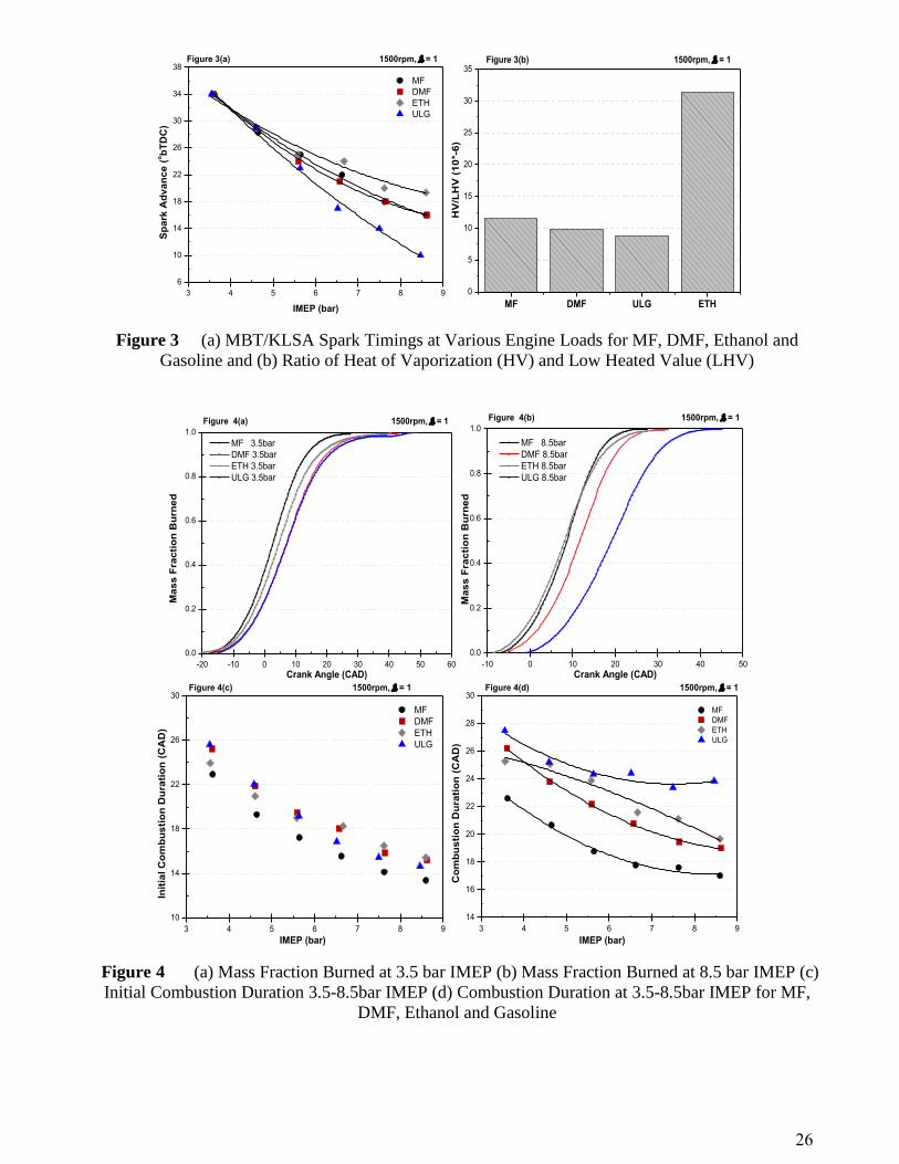
The fuel-specific optimized spark timings or MBT/KLSA timings at the various loads are shown in
Fig.3 (a). At 3.5 bar IMEP, there is no difference in the MBT/KLSA locations for all fuels. However,
as the load increases from 4.5 bar IMEP, the MBT/KLSA locations for all the fuels start to differ. MF
has similar MBT/KLSA locations with DMF within the entire load range. Ethanol allows the most
advanced spark timing while the MBT/KLSA for gasoline is the most retarded. At the highest load (8.5
bar IMEP), the MBT/KLSA timing for MF is 6 CAD more advanced than gasoline. The maximum
difference between MF and ethanol is 5 CAD at the highest load. Within the entire load range, the
knock phenomenon can be observed when using MF, as well as DMF and gasoline. For MF and DMF
knock starts to occur at 6.5 bar IMEP whereas for gasoline this is limited to 5.5 bar IMEP. No knock is
observed when using ethanol.
The knock suppression ability of each fuel is related to their octane number which partially depends
on the chemical structure. MF (C5H6O) is similar to DMF (C6H8O) in terms of chemical structure; the
only exception is MF has one less methyl on its cyclobenzene ring. The molecule of MF is relatively
simple and compact whilst gasoline is a mixture of C2-C14 hydrocarbons. Overall, the chain of
gasoline is the longest and the most complicated among the four studied fuels. Ethanol has the simplest
and the most compact structure, of which its carbon atom number is only two. As the hydrocarbon
chain length increases, the fuel becomes easier to break down when exposed to high temperatures,
which increases the tendency to knock when used in a SI engine. This can be one of the reasons why
MF (compact structure), unlike gasoline (long chain), has greater knock resistance.
The combustion temperature history is another important factor affecting the knock suppression
ability of the fuel. This can also be influenced by the evaporative cooling effect following DI fuel
supply. During the vaporization process, liquid fuel absorbs heat from ambient air, which lowers the in-
cylinder air temperature. The ratios of heat of vaporization (HV) and lower heating value (LHV) used
7
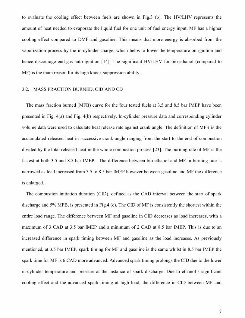
to evaluate the cooling effect between fuels are shown in Fig.3 (b). The HV/LHV represents the
amount of heat needed to evaporate the liquid fuel for one unit of fuel energy input. MF has a higher
cooling effect compared to DMF and gasoline. This means that more energy is absorbed from the
vaporization process by the in-cylinder charge, which helps to lower the temperature on ignition and
hence discourage end-gas auto-ignition [14]. The significant HV/LHV for bio-ethanol (compared to
MF) is the main reason for its high knock suppression ability.
3.2. MASS FRACTION BURNED, CID AND CD
The mass fraction burned (MFB) curve for the four tested fuels at 3.5 and 8.5 bar IMEP have been
presented in Fig. 4(a) and Fig. 4(b) respectively. In-cylinder pressure data and corresponding cylinder
volume data were used to calculate heat release rate against crank angle. The definition of MFB is the
accumulated released heat in successive crank angle ranging from the start to the end of combustion
divided by the total released heat in the whole combustion process [23]. The burning rate of MF is the
fastest at both 3.5 and 8.5 bar IMEP. The difference between bio-ethanol and MF in burning rate is
narrowed as load increased from 3.5 to 8.5 bar IMEP however between gasoline and MF the difference
is enlarged.
The combustion initiation duration (CID), defined as the CAD interval between the start of spark
discharge and 5% MFB, is presented in Fig.4 (c). The CID of MF is consistently the shortest within the
entire load range. The difference between MF and gasoline in CID decreases as load increases, with a
maximum of 3 CAD at 3.5 bar IMEP and a minimum of 2 CAD at 8.5 bar IMEP. This is due to an
increased difference in spark timing between MF and gasoline as the load increases. As previously
mentioned, at 3.5 bar IMEP, spark timing for MF and gasoline is the same whilst in 8.5 bar IMEP the
spark time for MF is 6 CAD more advanced. Advanced spark timing prolongs the CID due to the lower
in-cylinder temperature and pressure at the instance of spark discharge. Due to ethanol’s significant
cooling effect and the advanced spark timing at high load, the difference in CID between MF and

8
ethanol is increased from 1 CAD at 3.5 bar IMEP to 2 CAD at 8.5 bar IMEP. Between MF and DMF,
their difference in CID maintains the same (2 CAD) throughout the entire load range.
The combustion duration (defined by 10%-90% MFB interval in CAD) at various loads for each fuel
is shown in Fig.4 (d). As presented, MF consistently has the shortest CD within the entire load range,
whilst gasoline the longest. Unlike the difference in CID, the difference in CD between MF and
gasoline increases with load. The maximum difference between MF and gasoline (7 CAD) can be seen
at 8.5 bar IMEP and the minimum difference (4 CAD) is at 3.5 bar IMEP. The CD for MF at 8.5 bar
IMEP is about 3 and 2 CAD shorter than ethanol and DMF, respectively.
The faster burning rate of oxygenized hydrocarbon has already reported by many publications [24-
26]. This can also be used to explain why MF, like DMF and ethanol, has a shorter CD compared with
gasoline (no oxygen element in its molecule). The benefit of shorter CID and CD for MF is higher
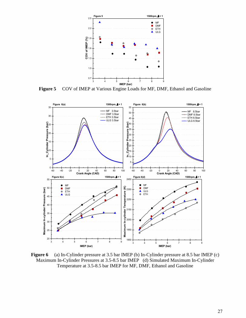
combustion stability as shown in Fig.5. The coefficient of variations (COV) of IMEP for MF is
consistently lower than other three studied fuels. Higher combustion stability indicates that MF has an
advantage when used in lean burn or deep stratified combustion modes. The chance of misfire is
minimized and unburned HCs dramatically lowered.
3.3. IN-CYLINDER PRESSURE AND TEMPERATURE
The in-cylinder pressure for four tested fuels at 3.5 and 8.5 bar IMEP have been presented in Fig. 6(a)
and Fig. 6(b) respectively. At 3.5 bar IMEP, MF has much highest in-cylinder pressure between 10-20
CAD. At 8.5 bar IMEP, the in-cylinder pressure for MF and bio-ethanol almost matches and both are
higher than DMF and gasoline.
The maximum in-cylinder pressure at various loads for each fuel is shown in Fig.6 (c). MF
consistently produces the highest in-cylinder peak pressure within the entire load range. Its maximum
in-cylinder pressure does not peak at 8.5 bar IMEP. As expected, gasoline has the lowest peak pressure
among the four fuels, which peaks near 7.5 bar IMEP. The difference between MF and gasoline in peak

9
pressure increases as load increases, with 4 and 15bar difference at 3.5 and 8.5 bar IMEP, respectively.
Even though MF has higher peak pressure than ethanol, their differences decrease as load increases. At
3.5 bar IMEP, the peak pressure for MF is 2.8 bar higher than ethanol. However, at 8.5 bar IMEP, their
peak pressures are nearly the same. As to MF and DMF, their peak pressure differences keep almost
constant within the entire load range, which is consistent with their constant differences in combustion
duration.
There are two major factors that attribute to the significant high peak pressure for MF: advanced
spark timing and short combustion duration. Shorter combustion duration for MF leads to more
accumulated energy released around top dead centre (TDC), which has significantly positive effect on
its peak in-cylinder pressure. MF has the same spark timing with DMF within the entire load range.
However due to its shorter combustion duration, its peak pressure is consistently higher than DMF. The
combination of advanced spark timing and shorter combustion duration makes MF to generate much
higher peak pressure than gasoline.
The theoretical maximum in-cylinder temperature shown in Fig.6 (d) is calculated using a detailed
engine gas-dynamics and thermodynamics model firstly described in [13], where the match of
experimental and simulated IMEP and maximum pressure is remarkably good. Some fundamental
assumptions are made according to the book by Heywood [23]. The model does not include detailed
chemical kinetics because the reaction mechanisms are very complex. Instead, the ideal gas law is used
and combined with the prediction of trapped residuals and fuel vaporization behavior to estimate the
in-cylinder gas temperature. The results represent the global averaged gas temperatures for MF, DMF,
bio-ethanol and gasoline. When simulating the combustion of gasoline, the fluid properties of indolene
were used. The known fuel properties of MF and DMF were inputted but some unknown properties,
such as the viscosity-temperature behavior, were taken from indolene. The SI Wiebe combustion sub-
model was also used and this required the input of CA50 and CAD10-90, in order to match in-cylinder

10
peak temperature and IMEP to within 99.5%. The model was validated using known combustion
performance data to maintain the volumetric efficiencies (VE) to within 5% at all tested engine loads.
As load increases peak temperature increases for each fuel. MF generates the highest peak
temperature whilst ethanol the lowest. Peak temperature, like peak pressure, is highly dependent on
spark timing and combustion duration. The trend of peak temperature and peak pressure in MF as well
as DMF and gasoline is consistent. Although MF case has the same spark timing with DMF, the shorter
combustion duration of MF makes its peak temperature higher than DMF. As burning rate increases,
heat release rate during combustion process increases, which contributes to generate higher peak
temperature. The MF case has significant higher peak temperature than ethanol. This is due to not only
shorter combustion duration of MF, but also the ethanol’s significant cooling effect which lowers its
initial combustion temperature as well as combustion temperature.
3.4. INDICATED THERMAL EFFICIENCY
The indicated thermal efficiencies (including pumping loss) at various loads for each fuel are shown
in Fig.7. The performance of MF is better than gasoline and DMF during the entire load range. At
8.5bar IMEP, the indicated thermal efficiency for MF is 1.4% and 2.7% higher compared to DMF and
gasoline, respectively. The indicated thermal efficiency for MF peaks around 7.5-8.5bar IMEP whilst
gasoline peaks around 6.5-7.5bar IMEP.
Heat transfer loss is one important negative factor on indicated thermal efficiency. Higher
combustion temperature encourages more heat transfer loss to the cylinder wall. The significant high
combustion temperature (indicated by peak in-cylinder pressure) of MF is one main reason that its net
indicated thermal efficiency is lower than that of ethanol.
11
3.5. COMBUSTION EFFICIENCY
The combustion efficiency is presented in Fig.8 to describe the completeness of combustion. In spark
ignition engine running under stroichiometric air-fuel ratio, the combustion efficiency is between 92-
98% [23]. The incomplete combustion is due to the unreleased chemical energy contained in
incompletely combusted products, such as CO, H2, and unburned hydrocarbons. In this paper, the
expression used to calculate the combustion efficiency is as follows [23]:
Combustion Efficiency: 𝜂𝑐 = 1 −∑ 𝑥𝑖∗𝑄𝐿𝐻𝑉𝑖
[��𝑓𝑢𝑒𝑙/(��𝑎𝑖𝑟+��𝑓𝑢𝑒𝑙)]∗𝑄𝐿𝐻𝑉𝑓𝑢𝑒𝑙
(1)
where xi and QLHVirepresent the mass fractions and lower heating values (LHV) of HC, CO, nitric
oxide (NO) and hydrogen (H2), respectively.
It is clear that MF has higher combustion efficiency (96%) than DMF (95.7%) and gasoline (95.3%)
whilst ethanol (96.7%-97.5%) the highest. Combustion efficiency is closely related with combustion
temperature, which can be referenced by peak in-cylinder temperature (Fig.6 (b)). Higher combustion
temperature contributes to more complete combustion and HC post-oxidization during exhaust stroke.
This principle works with MF, gasoline, and DMF. Relative oxygen content in each fuel also another
important factor affects the level of combustion completeness. Higher oxygen element in fuel molecule
encourages the availability of oxygen during combustion, which helps to increase combustion
efficiency. Amongst the four fuels, the oxygen content in MF (O/C=0.2) is lower than ethanol
(O/C=0.5), which can explain that ethanol has advantages over MF in terms of combustion efficiency.
3.6. INDICATED SPECIFIC FUEL CONSUMPTION
The gravimetric indicated specific fuel consumptions (GisFC) for each fuel are shown in Fig.9 (a).
Within the entire load range, MF has about 12%-13% lower GisFC than ethanol due to its higher
energy density. Even though MF has 5.4% lower energy density (LHV in mass) than DMF, its
relatively higher indicated thermal efficiency makes its GisFC much closer (2.6%-3.7% higher) to

12
DMF. Due to the relatively higher energy density of gasoline, MF has disadvantage compared with
gasoline on GisFC. The dash line in Fig.9 (a) shows the gasoline GisFC for MF which is converted
from the measurement of MF fueling rate to corresponding gasoline fueling rate for the same energy
content [11]. It can be seen that MF is superior to gasoline in this sense as indicated by its higher
indicated thermal efficiency. The volumetric indicated specific fuel consumption (VisFC) is illustrated
in Fig.9 (b). MF is close to gasoline and DMF, and much less (30% less at 3.5 bar IMEP) than ethanol
in terms of VisFC.
3.7. GASEOUS EMISSIONS
The regulated emissions (NOx, HC, and CO) are presented in Fig.10. The formation of NOx is
exponentially dependant on the combustion flame temperature [23]. This trend is observed in Fig.10 (a)
and Fig.6 (b) (in-cylinder peak temperature). MF produces the highest NOx emissions due to its
significant in-cylinder peak temperature. The maximum difference in NOx emissions between MF and
other three fuels is at the lower load end 3.5 bar IMEP, where MF generates 82%, 281% and 40% more
NOx emissions than gasoline, ethanol and DMF, respectively. For each fuel, the NOx increases with
load, and a similar peak in-cylinder temperature trend with the load can also be seen in Fig.6 (b). It has
been reported that the relative NOx emissions can be related to fuel property, the H/C ratio [14, 27].
Fuel with higher H/C ratio indicates lower NOx emissions. For the present data, this principle applies.
The indicated specific hydrocarbon (HC) emissions for each fuel are shown in Fig. 10 (b). It is
distinct that MF has significant advantage on HC emissions over gasoline and DMF. The HC emissions
for MF have inverse relationship with load, which also can be seen for gasoline and DMF. This is
mainly due to the increased in-cylinder temperature with load. Higher temperature makes HC post-
oxidization much easier to take place. This trend is verified by the inverse relationship between the in-
cylinder peak temperature and HC emission for MF, DMF and gasoline.
Additionally, one more principle applies that the fuel with more oxygen element in their molecule
tends to produce lower HC emissions. Higher oxygen element in MF leads to lower HC emissions for
13
gasoline and DMF. However, the advantage of MF over gasoline and DMF in terms of HC emission
(measured by Horiba using FID detector) could be subjected to reduced sensitivity of FID to
oxygenated hydrocarbon, reported by Wallner [28] and Price et al [29].
The indicated specific carbon monoxide emissions (isCO) for each fuel at various loads are shown in
Fig.10(c). Generally, MF has higher CO emissions than gasoline and ethanol. CO emissions are highly
dependent on the fuel/air equivalence ratio, which dramatically increases as air fuel mixture becomes
rich. Even though all the tests are carried out with stoichiometric air fuel ratio, the homogenous level
for each fuel in the DI combustion chamber differs due to their spay characteristics and volatility
property; shorter spray penetration leads to lower chance of piston and cylinder wall wetting. Liquid
fuel firm on cylinder wall or piston top has difficulty to be fully evaporated. Lower volatility can also
deteriorate the homogenous level. Gasoline has advantages over MF in CO emissions. This is because
gasoline is relatively easier to form combustible mixture due to its significant volatility property.
Additionally, its high energy density leads to shorter injection time and shorter the fuel spray
penetration. All these tend to reduce spay impingement on the piston crown. This fact can be used to
explain why gasoline has the lowest CO emission level in most conditions. On the other hand, ethanol
fuel molecule is highly oxygenated; hence more oxygen is available for completed combustion [30],
which contributes to offsetting the disadvantage caused by the piston wetting. The overall effect is that
ethanol has lower CO emissions compared with DMF and MF.
The acetaldehyde (CH3CHO) and formaldehyde (CH2O) emissions for MF at a selected engine
upper-medium load condition (6.5bar IMEP) are presented in Fig. 11. The formaldehyde emission from
MF is 32.7ppm, which is much lower than gasoline (179.4ppm), ethanol (155.7ppm), and DMF
(68.4ppm). The acetaldehyde emission from MF at the same load is 32.3ppm, which is comparable to
DMF (26.1ppm) and methanol (26.3ppm), lower than gasoline (53.9ppm), and significantly lower than
ethanol (303.1ppm).
3.8. PM EMISSIONS

14
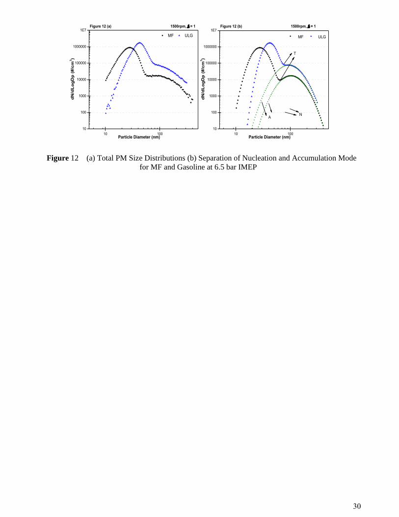
Typically, the PM size distribution consists of two modes [31]: the nucleation mode which usually
has more influence in number of particles and the accumulation mode which determines the particle
mass distribution due to its higher size. Fig.12 (a) shows the raw PM size distributions for MF and
gasoline at 6.5bar IMEP. For both MF and gasoline, there are overlaps between nucleation mode and
accumulation mode. Many researchers have used diameter range to separate nucleation and
accumulation mode. Kittelson suggested: nucleation mode (<50 nm), accumulation mode (50-1000 nm)
[32]. Eastwood suggested: nucleation mode (<100 nm), accumulation mode (100-900 nm) [31]. In this
study, two modes are separated using a Matlab script developed by University of Castilla-La Mancha
[33], which is shown in Fig.12 (b). The notations N, A and T mean nucleation mode, accumulation
mode and total PM emission distribution, respectively. A summary of PM emissions is listed in Table
3. MF has much smaller mean diameter (21.6nm) in nucleation mode than that of gasoline (41.7nm).
As to the mean diameter of accumulation mode, there is no apparent difference between those two
fuels. MF has 57.9% less number in nucleation mode and 238.3% less mass in accumulation mode
compared with gasoline. For MF, nucleation mode accounts for 97.1% and 19.5% in total number and
total mass respectively. For gasoline, those two figures are 92.2% and 25.5% respectively. The fuel
properties have direct impact on the PM emissions. High oxygenated fuels, like MF (O/C=0.2), tend to
produce less soot.
The soot level can dramatically affect the shape of the particle size distribution. Higher soot
emissions increase the chance of gaseous HC adsorption and condensation on its surface forming wet
coating, reducing the available hydrocarbons for nucleation. Hydrocarbons are adsorbed or condensed
on soot particles, which increase the size and increase the chance for wet soot to collide with each other
and form even bigger soot particles. Higher gaseous HC emissions tend to increase the total number of
particles and increase the mean diameter for both nucleation and accumulation mode. From Fig.10 (b),
it is clear that at 6.5bar IMEP, MF has the much lower HC emissions (3.63g/kWh) than that of gasoline
(5.98g/kWh). The higher oxygen content in MF molecule and lower HC emissions compared with that

15
of gasoline can be used to explain why MF has smaller mean diameter and lower number in nucleation
mode of PM emissions.
4. CONCLUSIONS
This paper examines the combustion performance and emissions of MF used in a single cylinder spray
guided DISI engine for the load condition of 3.5 to 8.5 bar IMEP at the engine speed of 1500 rpm and
stoichiometric air/fuel ratio. The results are compared with gasoline, ethanol and another promising
bio-fuel candidate, DMF. Based on the experimental results and analysis, the following conclusions
can be drawn:
1. Although MF has a similar chemical structure to DMF, its combustion characteristics are
notably different. MF has a much faster burning rate, which makes its CID and combustion
duration the shortest among the four studied fuels at equivalent engine conditions. At the
higher load end tested 8.5 bar IMEP, the combustion duration for MF is about 7, 3 and 2
CAD shorter than gasoline, ethanol and DMF, respectively. Its fast burning rate also makes
MF generate the highest in-cylinder peak pressure, which is even higher than for ethanol.
2. Similar to DMF, MF has better knock suppression ability than gasoline. This is due to its
simpler and more compact molecule structure and also faster burning rate. This makes MF a
competitive fuel to be used in higher compression ratio SI engines.
3. Due to the combined effect of significant knock suppression abilities, fast burning rate and
high in-cylinder peak pressure, MF consistently produces higher indicated thermal
efficiency than gasoline and DMF within the entire tested load range. At 8.5 bar IMEP, the
indicated thermal efficiency for MF is increased by 1.4% and 2.7% as compared with DMF
and gasoline respectively.
4. MF has the volumetric fuel consumption rate comparable with gasoline and DMF. MF has
significant advantage over ethanol with a lower VisFC (as typical, by 30% at 3.5 bar IMEP)

16
due to its relatively high energy density and mass density, despite of its lower indicated
thermal efficiency than the former.
5. At 8.5 bar IMEP, MF produces 73% and 40% less HC emissions than gasoline and DMF
respectively. This is mainly because of its high combustion temperature and high oxygen
content in its molecule. However, due to the high in-cylinder temperature, MF produces
higher NOx emissions. The maximum difference in NOx emissions between MF and the
other three fuels is at the lower load end tested 3.5 bar IMEP, where MF generates 82%,
281% and 40% more NOx emissions than gasoline, ethanol and DMF, respectively.
6. The formaldehyde emission from MF at the upper-medium load 6.5bar IMEP is 32.7 ppm,
which is the lowest among the four studied fuels. The acetaldehyde emission from MF at
6.5bar IMEP is 32.3 ppm, which is comparable to DMF and lower than gasoline and ethanol.
7. At 6.5bar IMEP, MF has 57.9% less PM number in nucleation mode and 238% less PM
mass in accumulation mode compared with gasoline. The mean diameter in nucleation
mode for MF (27.6 nm) is much smaller than that of gasoline (41.7 nm). The advantage for
MF over gasoline on PM emissions is linked to its lower HC emissions and higher oxygen
content in its molecule.
ACKNOWLEDGMENTS
This work was conducted in the Future Engines and Fuels Lab at the University of Birmingham and
financially supported by the Engineering and Physical Sciences Research Council (EPSRC) through
the Research Grant EP/F061692/1. The authors thank Peter Thornton and Carl Hingley for their
technical support of the engine testing facility and Farshad Eslami for his contribution to the
measurement of the calorific values of the tested fuels. The authors thank Dr Lixia Wei (Royal Society
sponsored Sino-British Research Fellow) for the contribution in helping with unregulated emission
results analysis.

17
REFERENCES
1. Kintisch E., ''Energy Research: BP Bets Big on UC Berkeley for Novel Biofuels Center,''
Science, 315(5813): 747, 2007.
2. Atsumi S., Hanai T., Liao J.C., '''Non-fermentative Pathways for Synthesis of Branched-Chain
Higher Alcohols as Biofuels,'' Nature, 451(7174): 86—89, 2008.
3. Demirbas A., ''Progress and Recent Trends in Biofuels,'' Pro. Energy and Combus Sci 33: p.1-
18, 2007.
4. Agarwal, A.K., ''Biofuels (Alcohols and Biodiesel) Applications as Fuels for Internal
Combustion Engines,'' Pro. Energy and Combust. Sci., 33 (3), p. 233–271, 2007.
5. Rakopoulos, D.C., Papagiannakis, R.G., Kyritsis, D.C., ''Combustion heat release analysis of
ethanol or n-butanol diesel fuel blends in heavy-duty DI diesel engine,'' Fuel, 90:1855-67, 2011.
6. Bika, A.S., Franklin, L., David, B.K., Hydrogen assisted combustion of ethanol in Diesel
engines, Department of Mechanical Engineering, University of Minnesota, Minneapolis MN
7. Scania, New highly efficient diesel-ethanol engine- ready to cut fossil CO2 emissions by 90%,
PRESS info, 2007 8. Zhao, H., Holladay, J.E., Brown, H. and Zhang, Z.C., "Metal Chlorides in Ionic Liquid
Solvents Convert Sugars to 5-Hydroxymethylfurfural," Science 316: p.1597–600, 2007.
9. Roman-Leshkov, R., Barrett, C.J., Liu, Z.Y. and Dumesic, J.A., "Production of Dimethylfuran
for Liquid Fuels from Biomass-Derived Carbohydrates," Nature 447: p. 982–986, 2010.
10. Dumesic, J.A., Roman-Leshkov, Y., and Chheda, J.N., "Catalytic Process for Producing Furan
Derivatives from Carbohydrates in a Biphasic Reactor," US: World Intellectual Property,
2007.
11. Yuriy Román-Leshkov, Biomass-Derived Furanic Compounds for the Production of Fuels and
Chemical Intermediates, Presentation, 2009.
12. Tian, G., Xu, H., Daniel, R., Biofuel Production-Recent Developments and Prospects, chapter
"DMF-A New Biofuel Candidate," 2011.
13. Zhong, S., Daniel, R., Xu, H., Wyszynski, M. L., "Combustion and Emissions of 2,5-
Dimethylfuran in a Direct-Injection Spark-Ignition Engine," Energy & Fuels, 24(5), p. 2891-
2899, 2010.
14. Daniel, R., Tian, G., Xu, H., Wyszynski, M.L., Wu, X. and Huang, Z., "Effect of Spark Timing
and Load on a DISI Engine Fuelled with 2,5-Dimethylfuran," Fuel 90: p. 449-458, 2011.
15. Wu, X., Daniel, R., Tian, G., Xu, H., Huang, Z. and Richardson, D., “Dual-Injection: the
Flexible, Bi-fuel Concept for Spark-Ignition Engines fuelled with Various Gasoline and Biofuel
Blends,'' Applied Energy 88: p. 2305-2314 , 2011.
18
16. Wu, X., Huang, Z., Jin, C., Wang, X., Zheng, B., Zhang, Y. and Wei, L., "Measurements of
Laminar Burning Velocities and Markstein Lengths of 2,5-Dimethylfuran Air Diluent Premixed
Flames," Energy Fuels 23: p. 4355–62, 2009.
17. Wu, X., Huang, Z., Yuan, T., Zhang, K. and Wei, L., ''Identification of the Combustion
Intermediates in a Low-Pressure Premixed Laminar DMF/Oxygen/argon Flame with Tunable
Synchrotron Photo Ionization,'' Combustion Flame 156: p. 1365-1376, 2009.
18. Tian, G., Xu, H., Daniel, R., Li, H., Shuai, S. and Richards, P., ''Laminar Burning Velocities of
DMF Compared with Ethanol and Gasoline,'' Energy & Fuels 7: p. 3898-3905, 2010.
19. Wu, X., Li, Q., Fu, J., Huang, Z., Daniel, R., Tian, G., Xu, H., ''Laminar burning
characteristics of 2-5-dimethylfuran and iso-octane blend at elevated temperatures and
pressures,'' Fuel, 95:234-240, 2012,
20. Li, Q., Fu, J., Wu, X., Tang, C., Huang, Z., ''Laminar flame speeds of DMF-iso-octane-air-
N2/CO2 mixtures,'' Energy and Fuels, 26(2): 917-9925, 2012,
21. Thewes, M., Muether, M., Pischinger, S., Budde, M., Brunn, A., Seher, A., Adomeit,. P.,
klankermayer, J., "Analysis of the Impact of 2-Methylfuran on Mixture Formation and
Combustion in a Direct-Injection Spark-Ignition Engine," Energy & Fuels, 25 (12), p. 5549–
5561, 2011.
22. California Environmental Protection Agency, Determination of Hazardous Air Pollutants from
Vapor Recovery Processors, 2001.
23. Heywood, J.B., Internal Combustion Engine Fundamental, McGraw-Hill Book Company, 1989.
24. Aleiferis, P., Malcolm, J., Todd, A., and Cairns, A., "An Optical Study of Spray Development
and Combustion of Ethanol, Iso-Octane and Gasoline Blends in a DISI Engine," SAE Technical
Paper 2008-01-0073, 2008.
25. Cairns, A., Stansfield, P., Fraser, N., and Blaxill, H., "A Study of Gasoline-Alcohol Blended
Fuels in an Advanced Turbocharged DISI Engine," SAE Int. J. Fuels Lubr. 2(1):41-57, 2009.
26. Yeliana, Cooney, C., Worm, J., and Naber, J., "The Calculation of Mass Fraction Burn of
Ethanol-Gasoline Blended Fuels Using Single and Two-Zone Models," SAE Technical Paper
2008-01-0320, 2008.
27. Harrington, J.A., and Shishu R.C., ''A Single-Cylinder Engine Study of the Effects of Fuel Type,
Fuel Stoichiometry, and Hydrogen-to-Carbon Ratio and CO, NO, and HC Exhaust Emissions,''
SAE 730476, 1973.
28. Wallner, T. and Miers, S., ''Combustion Behavior of Gasoline and Gasoline/Ethanol Blends in a
Modern Direct-Injection 4-Cylinder Engine,'' SAE Paper 2008-01-0077, 2008.
29. Price, P., Twiney, B., Stone, R., Kar, K.,Walmsley, H., ''Particulate and Hydrocarbon
Emissions from a Spray Guided Direct Injection Spark Ignition Engine with Oxygenate Fuel
Blends,'' SAE Paper 2007-01-0472, 2007.
30. Turnera, D., Xu, H., '''The Effect of Bio-Ethanol on Direct Injection Spark Ignition (DISI)
Engine Performance,'' Fuel 90: p. 1999–2006, 2011.

19
31. Eastwood P., Particulate Emissions from Vehicles. John Wiley & Sons. Inc., 2007.
32. Kittelson, D.B., "Engines and Nanoparticles: A RevieW," Journal of Aerosol Science 29 (5/6):
575-588, 1997.
33. Armas, O., G omez, A., and Mata, C., ''Methodology for Measurement of Diesel Particle Size
Distributions from A City Bus Working in Real Traffic Conditions,'' Measurement Science and
Technology 22, 105404 (11pp), 2011.
34. Janet, Y., Earl. C., and McCormick, R., ''Utilization of Renewable Oxygenates as Gasoline
Blending Components,'' National Renewable Energy Laboratory, 2011.

20
List of Tables
Table 1 Properties of the Fuels Studied
Table 2 Experimental Single Cylinder Engine Specification
Table 3 Summary of PM Emissions for MF and Gasoline at 6.5 bar IMEP
21
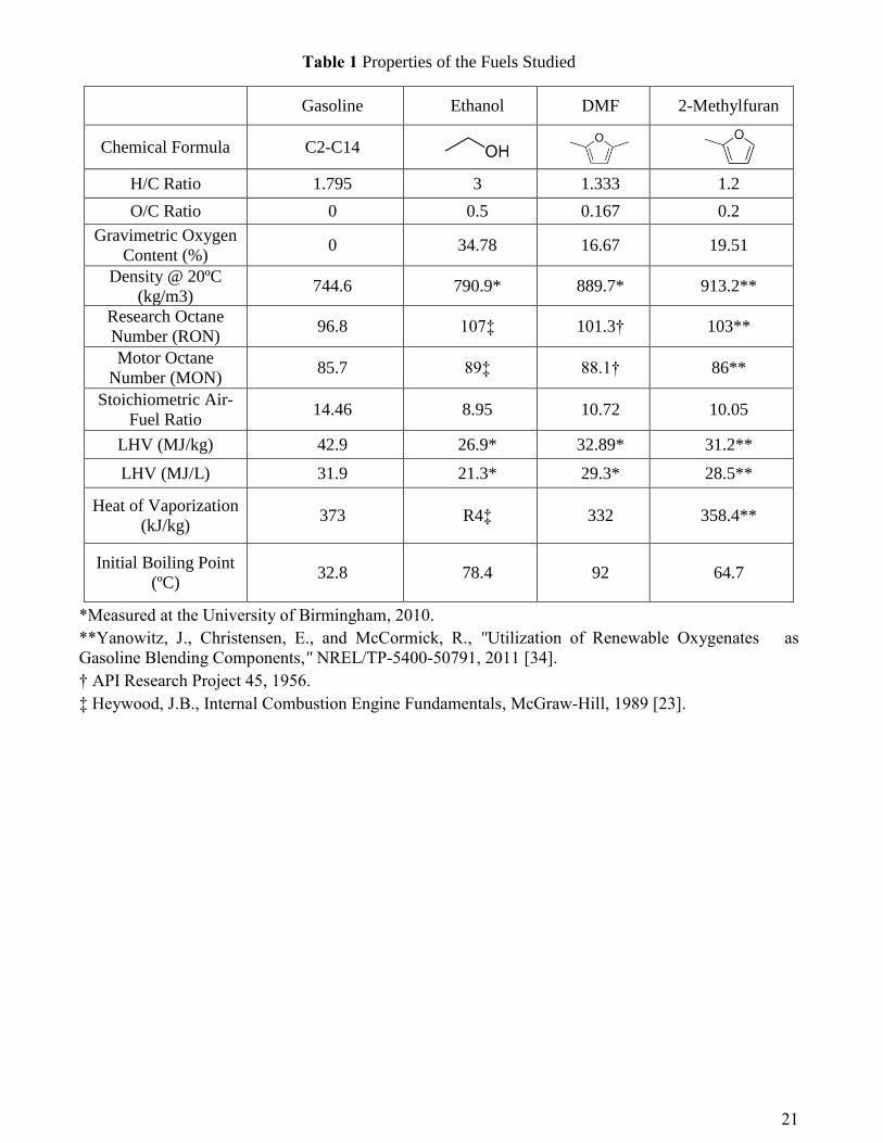
Table 1 Properties of the Fuels Studied
Gasoline Ethanol DMF 2-Methylfuran
Chemical Formula C2-C14
H/C Ratio 1.795 3 1.333 1.2
O/C Ratio 0 0.5 0.167 0.2
Gravimetric Oxygen
Content (%) 0 34.78 16.67 19.51
Density @ 20ºC
(kg/m3) 744.6 790.9* 889.7* 913.2**
Research Octane
Number (RON) 96.8 107‡ 101.3† 103**
Motor Octane
Number (MON) 85.7 89‡ 88.1† 86**
Stoichiometric Air-
Fuel Ratio 14.46 8.95 10.72 10.05
LHV (MJ/kg) 42.9 26.9* 32.89* 31.2**
LHV (MJ/L) 31.9 21.3* 29.3* 28.5**
Heat of Vaporization
(kJ/kg) 373 R4‡ 332 358.4**
Initial Boiling Point
(ºC) 32.8 78.4 92 64.7
*Measured at the University of Birmingham, 2010.
**Yanowitz, J., Christensen, E., and McCormick, R., "Utilization of Renewable Oxygenates as
Gasoline Blending Components," NREL/TP-5400-50791, 2011 [34].
† API Research Project 45, 1956.
‡ Heywood, J.B., Internal Combustion Engine Fundamentals, McGraw-Hill, 1989 [23].

22
Table 2 Experimental Single Cylinder Engine Specification
Engine Type 4-Stroke, 4-Valve
Combustion System Dual-Injection: Spray Guided DISI
Swept Volume 565.6 cc
Bore x Stroke 90 x 88.9 mm
Compression Ratio 11.5:1
Engine Speed 1500 rpm
DI Pressure and Injection Timing* 15MPa, 280º bTDC
Intake Valve Opening* 16.5º bTDC
Exhaust Valve Closing* 36.7º aTDC
*0º bTDC refers to TDC during 'valve overlap'
Table 3 Summary of PM Emissions for MF and Gasoline at 6.5 bar IMEP
Nucleation Mode Accumulation Mode
ULG MF ULG MF
Mean Diameter (nm) 41.7 27.6 94.7 102.8
Number (#/cm3) 3.71E+05 2.35E+05 31192 6903
Mass( g/cm3) 18.51 3.86 53.99 15.96

23
List of Figures
Figure 1 Paths for Converting Carbohydrates to MF (Roman-Leshkov et al, 2007)
Figure 2 (a) Schematic of Engine and Instrumentation Setup (b) 3D Cylinder Head Diagram
Figure 3 (a) MBT/KLSA Spark Timings at Various Engine Loads for MF, DMF, Ethanol and
Gasoline and (b) Ratio of Heat of Vaporization (HV) and Low Heated Value (LHV)
Figure 4 (a) Mass Fraction Burned at 3.5 bar IMEP (b) Mass Fraction Burned at 8.5 bar IMEP (c)
Initial Combustion Duration 3.5-8.5bar IMEP (d) Combustion Duration at 3.5-8.5bar IMEP for MF,
DMF, Ethanol and Gasoline
Figure 5 COV of IMEP at Various Engine Loads for MF, DMF, Ethanol and Gasoline
Figure 6 (a) In-Cylinder pressure at 3.5 bar IMEP (b) In-Cylinder pressure at 8.5 bar IMEP (c)
Maximum In-Cylinder Pressures at 3.5-8.5 bar IMEP (d) Simulated Maximum In-Cylinder
Temperature at 3.5-8.5 bar IMEP for MF, DMF, Ethanol and Gasoline
Figure 7 Indicated Thermal Efficiency at Various Engine Loads for MF, DMF, Ethanol and
Gasoline
Figure 8 Combustion Efficiency for MF, DMF, Ethanol and Gasoline at Various Engine Loads
Figure 9 Indicated Specific Fuel Consumption at Various Engine Loads for MF, DMF, Ethanol
and Gasoline
Figure 10 Indicated Specific Gaseous Emissions at Various Engine Loads for MF, DMF, Ethanol
and Gasoline
Figure 11 (a) Acetaldehyde and (b) Formaldehyde Emissions for MF, DMF, Ethanol and Gasoline
at 6.5bar IMEP

24
Figure 12 (a) Total PM Size Distributions (b) Separation of Nucleation and Accumulation Mode
for MF and Gasoline at 6.5 bar IMEP

25
Figure 1 Paths of Converting Carbohydrates to MF (Roman-Leshkov et al, 2007)
Figure 2 (a) Schematic of Engine and Instrumentation Setup (b) 3D Cylinder Head Diagram
Exhaust
VVT
Intake
VVT
Exhaust
Plenum
Chamber
Intake
Plenum
Chamber
Intake
Filter
Horiba
MEXA-
7100DEGR
Emissions
Analyser
(HC, CO, CO2,
O2, NOx)
TSI_SMPS
Lambda
Meter
Air In
Exhaust Oil/Water
Cooler
Crank Angle Encoder
VAF
MeterThrottle
Fuel
Accumulator
Compressed Nitrogen
Cylinder
Pressure Gauge
(150bar)
to DI
Injector
Kistler Pressure Sensor
High/Low Speed
Data AcquisitionControl Tower
100 Litre
Intake
Damper
T MAX.emf
Flow meter Pump
Ice waterHPLC
Heated
line
(a)
26
Figure 3 (a) MBT/KLSA Spark Timings at Various Engine Loads for MF, DMF, Ethanol and
Gasoline and (b) Ratio of Heat of Vaporization (HV) and Low Heated Value (LHV)
Figure 4 (a) Mass Fraction Burned at 3.5 bar IMEP (b) Mass Fraction Burned at 8.5 bar IMEP (c)
Initial Combustion Duration 3.5-8.5bar IMEP (d) Combustion Duration at 3.5-8.5bar IMEP for MF,
DMF, Ethanol and Gasoline
3 4 5 6 7 8 9
6
10
14
18
22
26
30
34
38Figure 3(a) 1500rpm, = 1
Sp
ark
Ad
va
nc
e (
ob
TD
C)
IMEP (bar)
MF
DMF
ETH
ULG
MF DMF ULG ETH
0
5
10
15
20
25
30
35Figure 3(b) 1500rpm, = 1
HV
/LH
V (
10
*-6
)
-20 -10 0 10 20 30 40 50 60
0.0
0.2
0.4
0.6
0.8
1.0
Ma
ss
Fra
cti
on
Bu
rne
d
MF 3.5bar
DMF 3.5bar
ETH 3.5bar
ULG 3.5bar
Figure 4(a) 1500rpm, = 1
Crank Angle (CAD)-10 0 10 20 30 40 50
0.0
0.2
0.4
0.6
0.8
1.0
MF 8.5bar
DMF 8.5bar
ETH 8.5bar
ULG 8.5bar
Figure 4(b) 1500rpm, = 1
Ma
ss
Fra
cti
on
Bu
rne
d
Crank Angle (CAD)
3 4 5 6 7 8 9
10
14
18
22
26
30Figure 4(c) 1500rpm, = 1
Init
ial C
om
bu
sti
on
Du
rati
on
(C
AD
)
IMEP (bar)
MF
DMF
ETH
ULG
3 4 5 6 7 8 9
14
16
18
20
22
24
26
28
30Figure 4(d) 1500rpm, = 1
Co
mb
us
tio
n D
ura
tio
n (
CA
D)
IMEP (bar)
MF
DMF
ETH
ULG
27
Figure 5 COV of IMEP at Various Engine Loads for MF, DMF, Ethanol and Gasoline
Figure 6 (a) In-Cylinder pressure at 3.5 bar IMEP (b) In-Cylinder pressure at 8.5 bar IMEP (c)
Maximum In-Cylinder Pressures at 3.5-8.5 bar IMEP (d) Simulated Maximum In-Cylinder
Temperature at 3.5-8.5 bar IMEP for MF, DMF, Ethanol and Gasoline
3 4 5 6 7 8 9
0.7
1.0
1.3
1.6
1.9
2.2
2.5Figure 5 1500rpm, = 1
CO
V o
f IM
EP
(%
)IMEP (bar)
MF
DMF
ETH
ULG
-60 -40 -20 0 20 40 60 80 100
0
5
10
15
20
25
30
35
MF 3.5bar
DMF 3.5bar
ETH 3.5bar
ULG 3.5bar
Figure 6(a) 1500rpm, = 1
In_
Cy
lin
de
r P
res
su
re (
ba
r)
Crank Angle (CAD)-60 -40 -20 0 20 40 60 80 100
0
5
10
15
20
25
30
35
40
45
50
55
MF 8.5bar
DMF 8.5bar
ETH 8.5bar
ULG 8.5bar
Figure 6(b) 1500rpm, = 1
In_
Cy
lin
de
r P
res
su
re (
ba
r)
Crank Angle (CAD)
3 4 5 6 7 8 9
20
25
30
35
40
45
50
55
MF
DMF
ETH
ULG
Figure 6(c) 1500rpm, = 1
Ma
xim
um
In
-cy
lin
de
r P
res
su
re (
ba
r)
IMEP (bar)
3 4 5 6 7 8 9
1850
1950
2050
2150
2250
2350
2450Figure 6(d) 1500rpm, = 1
Ma
xim
um
In
-cy
lin
de
r T
em
pe
ratu
re (
K)
IMEP (bar)
MF
DMF
ULG
ETH

28
Figure 7 Indicated Thermal Efficiency at Various Engine Loads for MF, DMF, Ethanol and
Gasoline
Figure 8 Combustion Efficiency for MF, DMF, Ethanol and Gasoline at Various Engine Loads
Figure 9 Indicated Specific Fuel Consumption at Various Engine Loads for MF, DMF, Ethanol
and Gasoline
3 4 5 6 7 8 9
0.32
0.34
0.36
0.38
0.40Figure 7 1500rpm, = 1
Ind
ica
ted
Th
erm
al E
ffic
ien
cy
IMEP (bar)
MF
DMF
ETH
ULG
3 4 5 6 7 8 9
0.950
0.955
0.960
0.965
0.970
0.975
0.980Figure 8 1500rpm, = 1
Co
mb
us
tio
n E
ffic
ien
cy
IMEP (bar)
MF DMF ETH ULG
3 4 5 6 7 8 9
200
250
300
350
400
450Figure 9(a) 1500rpm, = 1
iSF
C (
g/k
Wh
)
IMEP (bar)
MF
DMF
ETH
ULG
MF(ULG Equivalent)
3 4 5 6 7 8 9
0.25
0.30
0.35
0.40
0.45
0.50
0.55Figure 9(b) 1500rpm, = 1
iSF
C (
L/k
Wh
)
IMEP (bar)
MF
DMF
ETH
ULG

29
Figure 10 Indicated Specific Gaseous Emissions at Various Engine Loads for MF, DMF, Ethanol
and Gasoline
Figure 11 (a) Acetaldehyde and (b) Formaldehyde Emissions for MF, DMF, Ethanol and
Gasoline at 6.5bar IMEP
3 4 5 6 7 8 9
0
2
4
6
8
10
12Figure 10(a) 1500rpm, = 1
iSN
OX (
g/k
Wh
)
IMEP (bar)
MF
DMF
ETH
ULG
3 4 5 6 7 8 9
0
1
2
3
4
5
6
7Figure 10(b) 1500rpm, = 1
iSH
C (
g/k
Wh
)
IMEP (bar)
MF
DMF
ETH
ULG
3 4 5 6 7 8 9
15
20
25
30
35
40
MF
DMF
ETH
ULG
Figure 10(c) 1500rpm, = 1
iS
CO
(g
/kW
h)
IMEP (bar)
ETH DMF MF ULG
0
100
200
Figure 12 (a) 6.5bar IMEP 1500rpm, = 1
Fo
rma
lde
hy
de C
on
cen
traio
n (
pp
m)
ETH DMF MF ULG
0
100
200
300
400Figure 12 (b) 6.5bar IMEP 1500rpm, = 1
Aceta
ldeh
yd
e C
on
cen
traio
n (
pp
m)
30
Figure 12 (a) Total PM Size Distributions (b) Separation of Nucleation and Accumulation Mode
for MF and Gasoline at 6.5 bar IMEP
10 100
10
100
1000
10000
100000
1000000
1E7Figure 12 (a) 1500rpm, = 1
dN
/dL
og
Dp
(#
/cm
3)
Particle Diameter (nm)
MF ULG
10 100
10
100
1000
10000
100000
1000000
1E7
MF ULG
Figure 12 (b) 1500rpm, = 1
dN
/dL
og
Dp
(#
/cm
3)
Particle Diameter (nm)
T
NA

31
DEFINITIONS, ACRONYMS, ABBREVIATIONS
AFR Air-Fuel Ratio
aTDC After Top Dead Centre
bTDC Before Top Dead Centre
CAD Crank Angle Degree
CD Combustion Duration n Duration
CO Carbon Monoxide
CID Initial Combustion
COV Coefficient of Variations
CO2 Carbon Dioxide
DC Direct Current
DISI Direct Injection Spark Ignition
DMF 2,5-Dimethylfuran
FID Flame Ionization Detector
ETH Ethanol
GisFC Gravimetric Indicated Specific Fuel Consumption
HC Hydrocarbon
HMF 5-hydroxymethylfurfural
HV Heat of Vaporization
IMEP Indicated Mean Effective Pressure
isCO Indicated specific Carbon Monoxide
isHC indicated specific Hydrocarbon
KLSA Knock-limited Spark Advance
VisFC Volumetric Indicated Specific Fuel Consumption
LHV Lower Heating Value
MBT/KLSA Maximum Brake Torque/ Knock-Limited Spark Advance

32
MF 2-Methylfuran
MFB Mass Fraction Burned
NOx Nitrogen Oxides
PID Proportional Integral Differential
PM Particulate Matter
RPM Revolutions per Minute
SI Spark-ignition
TDC Top Dead Center
ULG Gasoline
VVT Variable Valve Timing
1. Kintisch, E., Energy research. BP bets big on UC Berkeley for novel biofuels center. Science,
2007. 315(5813): p. 747.
2. Atsumi, S., T. Hanai, and J.C. Liao, Non-fermentative pathways for synthesis of branched-chain
higher alcohols as biofuels. Nature, 2008. 451(7174): p. 86–89.
3. A. Demirbas and Prog, Energy Combust. Sci. 33 (1) (2007) 1–18.
4. Agarwal, A.K., Bio-fuels (Alcohols and Biodiesel) Applications as fuels for Internal
Combustion Engines. Progress in Energy and Combustion Science, 2007. 33(3): p. 233-271.
5. Anil Singh Bika, L.F., Prof. David B. Kittelson, Hydrogen assisted combustion of ethanol in
Diesel engines.
6. Rakopoulos, D.C., et al., Combustion heat release analysis of ethanol or n-butanol diesel fuel
blends in heavy-duty DI diesel engine. Fuel, 2011. 90(5): p. 1855-1867.
7. Scania, New highly efficient diesel-ethanol engine– ready to cut fossil CO2 emissions by
90%2007: PRESS info.
8. Zhao, H., et al., Metal chlorides in ionic liquid solvents convert sugars to 5-
hydroxymethylfurfural. Science, 2007. 316(5831): p. 1597-600.
9. Roman-Leshkov, Y., et al., Production of dimethylfuran for liquid fuels from biomass-derived
carbohydrates. Nature, 2007. 447(7147): p. 982-5.
10. Dumesic, J.A., Y. Roman-Leshkov, and J.N. Chheda, Catalytic process for producing furan
derivatives from carbohydrates in a biphasic reactor, in US: World Intellectual Property2007.

33
11. Yuriy Román-Leshkov, Biomass-derived furanic compounds for the production of fuels and
chemical intermediates. 2009.
12. Tian, G., R. Daniel, and H. Xu, DMF-A New Biofuel Candidate2011.
13. Zhong, S.H., et al., Combustion and Emissions of 2,5-Dimethylfuran in a Direct-Injection
Spark-Ignition Engine. Energy & Fuels, 2010. 24(5): p. 2891-2899.
14. Daniel, R., et al., Effect of spark timing and load on a DISI engine fuelled with 2,5-
dimethylfuran. Fuel, 2011. 90(2): p. 449-458.
15. Wu, X.S., et al., Dual-injection: The flexible, bi-fuel concept for spark-ignition engines fuelled
with various gasoline and biofuel blends. Applied Energy, 2011. 88(7): p. 2305-2314.
16. Wu, X.S., et al., Measurements of Laminar Burning Velocities and Markstein Lengths of 2,5-
Dimethylfuran-Air-Diluent Premixed Flames. Energy & Fuels, 2009. 23: p. 4355-4362.
17. Tian, G.H., et al., Laminar Burning Velocities of 2,5-Dimethylfuran Compared with Ethanol
and Gasoline. Energy & Fuels, 2010. 24(7): p. 3898-3905.
18. Wu, X.S., et al., Laminar burning characteristics of 2,5-dimethylfuran and iso-octane blend at
elevated temperatures and pressures. Fuel, 2012. 95(1): p. 234-240.
19. Li, Q., et al., Laminar flame speeds of DMF-iso-octane-air-N2/CO2 mixtures. . Energy & Fuels,
2012. 25(2): p. 917-925.
20. Wu, X., et al., Identification of combustion intermediates in a low-pressure premixed laminar
2,5-dimethylfuran/oxygen/argon flame with tunable synchrotron photoionization. Combustion
and Flame, 2009. 156(7): p. 1365-76.
21. Thewes, M., et al., Analysis of the Impact of 2-Methylfuran on Mixture Formation and
Combustion in a Direct-Injection Spark-Ignition Engine. Energy & Fuels, 2011. 25(12): p.
5549-5561.
22. Agency, C.E.P., Determination of Hazardous Air Pollutants from Vapor Recovery Processors,
2001.
23. Heywood, J.B., Internal combustion engine fundamentals. McGraw-Hill Book Company1989.
24. Aleiferis, P.G., et al., An optical study of spray development and combustion of ethanol, iso-
octane and gasoline blends in a DISI engine, 2008, SAE International.
25. Cairns, A., et al., A study of gasoline–alcohol blended fuels in an advanced turbocharged DISI
engine, in SAE International2009.
26. Yeliana, et al., The calculation of mass fraction burn of ethanol–gasoline blended fuels using
single and two-zone models. , 2008, SAE International.
27. Harrington, J.A. and R.C. Shishu, A single-cylinder engine study of the effects of fuel type, fuel
stoichiometry, and hydrogen-to-carbon ratio and CO, NO, and HC exhaust emissions, 1973,
SAE International.
28. Wallner, T. and S.A. Miers, Combustion Behavior of Gasoline and Gasoline/Ethanol Blends in
a Modern Direct-Injection 4-Cylinder Engine, 2008, SAE International.
29. P., P., et al., Particulate and Hydrocarbon Emissions from a Spray Guided Direct Injection
Spark Ignition Engine with Oxygenate Fuel Blends, 2007, SAE International.
30. Dale Turnera, et al., Combustion Performance of Bio-Ethanol at Various Blend Ratios in a
Gasoline Direct Injection Engine. Fuel, 2011. 90(5): p. 1999-2006.
31. Eastwood, P., Particulate Emissions from Vehicles2007: John Wiley & Sons, Inc.
32. Kittelson, D.B., Engines and nanoparticles: A review. Journal of Aerosol Science, 1998. 29(5-
6): p. 575-588.
33. Armas, O., A. Gomez, and C. Mata, Methodology for measurement of diesel particle size
distributions from a city bus working in real traffic conditions. Measurement Science &
Technology, 2011. 22(10).
34. Yanowitz, J., E. Christensen, and R.L. McCormick, Utilization of Renewable Oxygenates as
Gasoline Blending Components. National Renewable Energy Laboratory2012: BiblioGov.