UNIVERSITI TEKNIKAL MALAYSIA MELAKA -...
24
UNIVERSITI TEKNIKAL MALAYSIA MELAKA DEVELOPMENT OF LED CHARACTERISTIC FOR TRAFFIC LIGHT This report submitted in accordance with requirement of the Universiti Teknikal Malaysia Melaka (UTeM) for the Bachelor Degree of Manufacturing Engineering (Robotic Automation) with Honours. by MOHAMAD NAZZREIN BIN ABD AZIZ FACULTY OF MANUFACTURING ENGINEERING
Transcript of UNIVERSITI TEKNIKAL MALAYSIA MELAKA -...

UNIVERSITI TEKNIKAL MALAYSIA MELAKA
DEVELOPMENT OF LED CHARACTERISTIC FOR
TRAFFIC LIGHT
This report submitted in accordance with requirement of the Universiti Teknikal
Malaysia Melaka (UTeM) for the Bachelor Degree of Manufacturing Engineering
(Robotic Automation) with Honours.
by
MOHAMAD NAZZREIN BIN ABD AZIZ
FACULTY OF MANUFACTURING ENGINEERING

UNIVERSITI TEKNIKAL MALAYSIA MELAKA
BORANG PENGESAHAN STATUS LAPORAN PROJEK SARJANA MUDA
TAJUK:
SESI PENGAJIAN: 2009/10 Semester 2
Saya, MOHAMAD NAZZREIN BIN ABD AZIZ
mengaku membenarkan Laporan PSM ini disimpan di Perpustakaan Universiti Teknikal Malaysia Melaka (UTeM) dengan syarat-syarat kegunaan seperti berikut:
1. Laporan PSM adalah hak milik Universiti Teknikal Malaysia Melaka dan penulis. 2. Perpustakaan Universiti Teknikal Malaysia Melaka dibenarkan membuat salinan
untuk tujuan pengajian sahaja dengan izin penulis. 3. Perpustakaan dibenarkan membuat salinan laporan PSM ini sebagai bahan
pertukaran antara institusi pengajian tinggi.
4. **Sila tandakan (√)
SULIT
TERHAD
TIDAK TERHAD
(Mengandungi maklumat yang berdarjah keselamatan atau kepentingan Malaysia yang termaktub di dalam
AKTA RAHSIA RASMI 1972)
(Mengandungi maklumat TERHAD yang telah ditentukan
oleh organisasi/badan di mana penyelidikan dijalankan)
Alamat Tetap:
Kg Serom 5,
84410 Sg. Mati
Muar,Johor Tarikh: _________________________
Disahkan oleh:
Cop Rasmi: Tarikh: _______________________
** Jika Laporan PSM ini SULIT atau TERHAD, sila lampirkan surat daripada pihak berkuasa/organisasi berkenaan dengan menyatakan sekali sebab dan tempoh laporan PSM ini perlu dikelaskan sebagai
SULIT atau TERHAD.
DEVELOPMENT OF LED CHARACTER FOR TRAFFIC LIGHT

APPROVAL
This report is submitted to the faculty of manufacturing engineering of UTeM as a
partial fulfillment of the requirement for the degree of Bachelor of Manufacturing
Engineering (Robotic and Automation) with honor. The member of the supervisory
committee is as follow:
…………………………..
(PSM Supervisor)
MR. KHAIROL ANUAR BIN RAKIMAN

DECLARATION
I hearby, declared this report entitled” LED CHARACTERISTIC DISPLAY FOR
TRAFFIC LIGHT” is the result of my own research except as cited in the references.
Signature : …………………………………………….
Author’s Name : …………………………………………….
Date : …………………………………………….
ABSTRACT
LED display is the common medium that we can see nowadays. LED display applications
have been used widely in variation human life such as for the score board, for the main
entrance, on the road, for the advertisement and many more. But for there are no once
design and develop to the traffic light. So that, in this paper will design and develop a
new LED display characteristic for traffic light. For the common LED display there have
their own software, on the other hand this project will develop with the software for
fabrication the circuit and the programming the coding. For the circuit fabrication is using
the Proteus software and the programming the coding use the Micro-C software. The
programming is using the C code for overall.

ABSTRAK
Penggunaan paparan LED ( Pemancar Cahaya Diode) merupakan salah satu alat atau
medium yang biasa dihat. Penggunaan paparan LEd telah meluas dalam kehidupan
seharian manusia seperti alat papan markah untuk sukan,paparan pada pintu masuk,pintu
keluar, petunjuk arah diatas jalan dan sebagainya. Pada masa ini belum lagi dicipta
paparan tersebut untuk diaplikasikn pada lampu isyarat di Malaysia sebagai contoh
apabila lampu merah menyala paparan LED tersebut menunjukkan perkataan” berhenti”
atau sebagaimnya. Hal ini secara tidak langsung dapat memberikan nasihat atau amaran
kepada pengguna jalan raya.Selainitu “software” yang terlibat adalah “Proteus” yg
digunakan untuk membuat litar dan “Micro-C” dalam pembinaan kod-kod data untuk
paparan LED dan lampu isyarat.

ACKNOWLEDGEMENTS
First of all, I would like to express my deepest thankful and gratitude to Allah
SWT who gave me spirit and soul throughout the duration of my final year project.
Endless appreciation and gratitude to my supervisor, Mr. Khairol Anuar Bin Rakiman
who tolerated from the beginning of the report until completion. and for the helpful
lecturer Mr. Herman Bin Jamalluddin who conduct me to finish the project. However,
special thanks must first go to my family, who over the duration has been neglected even
ignored, during my deepest concentrations.
Secondly, it is difficult to name all the people who have directly or indirectly
helped me in this effort; an idea here and there may have appeared insignificant at the
time but may have had a significant causal effect. In addition, deeply acknowledge who
involved directly and indirectly for their never ending encouragement, moral support and
patience during the duration of final year project. For all your advice and encouragement,
this thesis is gratefully dedicated to my family and my friends. Thank you very much for
your continuous support towards the publication of this thesis.
Last but not least, I take this opportunity to dedicate this thesis for all
manufacturing engineering students. All suggestions for further improvement of this
thesis are welcome and will be gratefully acknowledged.


LIST OF TABLES
Table 4.1: The component used in this circuit 48
Table 4.2: Periperal support by Proteus 63
Table 5.1: Shows the result for the circuit testing to measure the voltage. 74
Table 5.2: Show the result for the LED characteristic for traffic light 78

TABLE OF CONTENT
Abstract i
Abstrak ii
Acknowledgement iii
Table of Content iv
List of Tables v
List of Figures vi
List of Abbreviation vii
1.0 INTRODUCTION 1
1.1 Overview 1
1.2 The problem statement 3
1.3 Objective 4
1.4 Scope 4
2.0 LITERATURE REVIEW 5
2.1 History 5
2.2 Introduction 6
2.3 Overview on LED Display Characteristic 7
2.4 Larger LED display Have Be Multiplexed 8
2.5 Operation of the System 14
2.6 LED Display Action 15
2.6.1 Indoor LED display 16
2.6.2 Outdoor LED display 16
2.7 Alphabetic display 17
2.8 LED non-colors display 17
2.8.1 Seven- segment scoreboard 18
2.8.2 Fourteen-segment display 19

2.8.3 Nixie tube 20
2.9 Type Of The Led Display 22
2.9.1 Single line led display 22
2.9.2 Double line led display 22
2.9.3 Three or Four line LED display. 23
2.9.4 Multi-line led display 23
2.10 LED with colors display 25
2.10.1 Liquid-Crystal displays 26
2.10.2 Basic LCDs display woks 26
2.11 Components Features Consider In Selection Process 27
2.11.1 Light emitting diode (LED) 27
2.11.2 Peripheral Interface Controller (PIC) 28
2.11.2.1 Data space (RAM) 30
2.11.2.2 Character Map or character generator ROM (CGROM) 31
2.12 Conclusion 33
3.0 METHODOLOGY 34
3.1 Introduction 34
3.2 Scope of methodology 35
3.3 Analyze the existing design 36
3.4 Programming the software 36
3.4.1 Programming environments 37
3.5 Circuit fabrication 39
3.5.1 Layout Database 41
3.5.2 Shape Based Auto routing 41
3.5.3 Power Planes 43
3.5.4 3D Visualization 44
3.6 Assemble 45
3.7 Testing and analyzing 46

4.0 CIRCUIT FABRICATION AND PROGRAMMING 47
4.1 Circuit Fabrication 48
4.2 Bill of material 48
4.2.1 PIC16F877A 49
4.2.2 MAX232 50
4.2.3 Crystal oscillator 51
4.2.4 Voltage regulator 52
4.2.5 Resistor 53
4.2.6 Capacitor 54
4.2.7 Electrolytic 55
4.3 Proteus software 57
4.3.1 Basic drawing 58
4.3.2 3D Visualization 59
4.3.3 Auto routing 60
4.3.4 Power planes 62
4.3.5 Peripheral Support 63
4.3.6 The benefit 64
4.4 Programming the coding 65
4.4.1 Material 65
4.4.2 The Programming for this project 68
4.4.3 Programming the microcontroller 70
5. 0 RESULT AND ANALYSIS 72
5.1 Background 72
5.2 Operation of System 73
5.3 Result 74
5.3.1 Testing Performance 74
5.3.1.1 Circuit Test 74
5.3.1.2 Coding Test 76
5.3.1.3 The finding 79

6..0 CONCLUSION 80
6.1 Conclusion 80
6.2 Recommendations 81

1
CHAPTER 1
INTRODUCTION
1.1 Overview
Traffic light also known as traffic signals, stop lights, stoplight, traffic lamps, stop-and-
go lights, robots or semaphore are signaling devices positioned at road intersections,
pedestrian crossings and other location to control completti9ng flows of traffic. Traffic
light has been installed in most cities around the world to control the flow of traffic.
They assign the right of way to road users by the use of light in standard color (Red-
Amber-green), using a universal color code (and a precise sequence, for those who are
color blind.). They are used at the intersection to more evenly apportion delay to the
various users. The most common traffic lights consist of a set of three lights: red yellow
(officially amber), and green. When illuminated, the light indicates for vehicles facing
the light to stop: the amber indicates caution, either because lights are about to turn
green or because lights are about to turn red; and the green light to proceed, if it is safe
to do so.
There are many variations in the use and legislation of traffic lights, depending on the
customs of a country and the special needs of a particular intersection. There may, For
examples, be special lights for pedestrians, bicycles, busses, tram, etc; light sequences
may differ; and there may be special rules, or sets of lights, for traffic running in
particular direction. Complex intersection may use any combination of these. Traffic

2
Light technology is constantly evolving with the aims of improving reliability, visibility
and efficiency of traffic flow.
In many regions, traffic light function differently or have different displays depending
on available technology, traffic patens ,or other vehicles such as trolleys that also use the
intersection .For examples, some fixtures are flashing green light found in Canada, to
notify drivers that they have the right of way and that the opposing lanes will not be
moving.
ED sign is the new technology that is used in many sectors such as in the school, in the
industry on the road and many more. This massage sign is very useful to the consumer
because on the road, this massage sign will shows about the condition of the road, about
the speed that car must follow and many more. Besides that, this LED sign help the
people to give information anywhere.
LED display is a video display which use light emitting-diodes (LED). There are two
types of LED panels: conventional using discrete LED surface mounted devices (SMD)
panels. Most outdoor screens and some indoor screen are built around discreet LED, also
known as individually mounted LED. A cluster of red, green, blue diodes are driven
together to form a full-color pixel, usually square in shape. These pixels are spaced
evenly apart and measured from center to center for absolute resolution. The largest
LED display in the world is over 1,500 foot (457.2 m) long and is located in Las Vegas,
Nevada covering the Fremont Street Experience.
This LED sign consist with many LED and give many type of variation output. The
major output are alphabet and numerical. For the numerical, usually using such as in the
digital clock, score board for the game, time for ticketing in the air port and many more.
But for the alphabet sign, there have many type of line such as one line massage, two
line massage and many more. Besides that, this Led massage sign is divided into two
types. There is outdoor appearance and indoor appearance. For indoor appearance,
usually using in the office, industry and many more. For the outdoor using on the road,
using as an advertisement and many more.

3
Perhaps the first recorded flat panel LED television screen developed was by J>P.
Mitchell in 1977. The modular, scalable display array was initially enabled by hundreds
of MV50 LED and a newly available TTL (transistor transistor logic) memory
addressing circuit from National Semiconductor. The ¼ inch thin flat panel prototype
ant the scientific paper were each displayed at the 29th
Engineering Exposition in
Anaheim May 1978, organized by the Sciences Service in Washington D.C. The LED
TV display received awards and recognition from NASA, General Motor Corporation,
and faculty from area Universities. The event was open to technology and business
representatives from the U.s and overseas. The monochromatic prototype remains
operational. A LCD (liquid crystal display) matrix design was also cited as a future flat
panel TV possibility in the accompanying scientific paper as a future alternate television
display method using a similar array scanning design. Additionally, Mitchell presents his
paper at the 90th
Session of The Iowa Academy of Sciences April 21-22, 1978, at the
University of Northern Iowa, Cedar Falls, Iowa. In order to develop a color display,
triads of red, green and blue LED are needed. Efficient blue LED did not emerge until
the early 1990s. High-brightness colors gradually emerged in the 1990s enabling new
design for outdoor signage and huge video display for billboards stadiums.
1.2 The problem statement
Many accidents occur at the traffic light. From the observation and the analysis, there
are many accidents occur at the traffic light. This is because the consumer did not pay
attention and they take easy at the traffic light. The people also always speeding when
the count is go down. In this project is focus about the LED display for the traffic light.
The analysis is to construct this LED display for the traffic light to give more efficiency
to the traffic light and avoid the accident occurs.
Besides that blind color people cannot use the road because of the blind color people
cannot differentiate the red and green color. So with this project will help the blind color
people to use the highway such as and help them to get the license.

4
1.3 Objective
To develop a circuit for the LED display and traffic light.
To create the programming for the Peripheral Integrated Control (PIC) to
control the LED display and traffic light.
To develop the connection between LED display and traffic light.
1.4 Scope
This project is focus all about the circuit, the design of the circuit, connection and the
software that will use. Also cover about fabricating and assembling process of the circuit
and the connection besides for the programming also. The aiming is all about LED
characteristic output after traffic light appear the signal. This project is focus all about
the circuit, the design of the circuit, connection and the software that will use. Also
cover about fabricating and assembling process. The aiming is all about LED
characteristic output after traffic light appear the signal.
For the Led characteristic display we have to build it for the traffic light. Such as when
the traffic light appears the red, automatically the display will appear such as “stop,
danger or something else. Its mean that with this display characteristic we will give
some advice to the consumer to be more be careful on the road. Besides that, with this
display characteristic for the traffic light, we also have to develop the traffic light system
in Malaysia to be more helpful.

5
CHAPTER 2
LITERATURE REVIEW
2.1 History
Helen Gardner said LED, light emitting diodes; have been around for more than 30
years. This simple junction semiconductor emits continuous light when current flows
through its junction at a low voltage. The LED has proved quite useful as a power-
saving indicator lamp. It is bright, has a fairly wide viewing angle, and can be arranged
into matrices to display text, numerals, and even crude pictures. LED also come in a
variety of colors, including red, green, and blue which are the building blocks of any
color imaging system. Although capable of displaying many colors, the applications of
LED displays are not intended to replace small-screen imaging. They are aimed at
larger-than-life electronic displays, particularly those that must work under unforgiving
ambient lighting. Typical applications would be at tradeshows, along highways, and in
stadiums and arenas under full daylight or artificial lighting at nighttime.
To our knowledge, there are only a few companies in the world that manufacture LED
displays. Each company has its own strictly guarded secret technology. Our research
project was designed to find both hardware and software solutions for creating our own
LED display technology. Several decades had passed from the first Light emitting diode
(LED) application for the imaging. The latest traced paper was dated before 1974 .
Nowadays LED displays are used in road and railway signage facilities, banks, stock
exchanges, airports, advertising, etc. This device presents the superlative source of

6
information and video image display with a wide viewing angle and a bright and clear
image. Similar to other semiconductor devices which consist of a PN junction, an LED
needs to be driven by a DC voltage source in order to generate color illumination.
2.2 Introduction
In 21st century, high data rate transmission will pervasively play an important role in our
life. LED is more advantageous than the existing incandescent in terms of long life
expectancy, high tolerance to humidity, low power consumption, and minimal heat
generation. LED is used in full color displays, traffic signals, and many other means of
illumination. By mixing three primary colors (red, green and blue), white color can be
produced. This white LED is considered as a strong candidate for the future lighting
technology .Compared with conventional lighting methods, white LED has lower power
consumption, lower voltage, longer lifetime, smaller size, and cooler operation. The
Ministry of Economy, Trade and Industry of Japan estimates, if LED replaces half of all
incandescent and fluorescent lamps currently in use, Japan could save equivalent output
of six midsize power plants, and reduce the production of greenhouse gases. A national
program underway in Japan has already suggested that white LED deserves to be
considered as a general lighting technology of the 21st century owing to electric power
energy consumption.

7
2.3 Overview on LED Display Characteristic
LED characteristic display is a device or one of the medium for the advertisement. It can
give the advice, indication, for advertisement and etc. For this project it will be attach to
the traffic light to give the information such as when the indicator shows red it ‘stop’ for
the green “go’ and for the orange indicator will appear ‘ready’. LED’s are made of a
semiconductor material in which light is produced when an electron within the
semiconductor material travels from a high-energy state to a low-energy state. This
process will release a photon at the appropriate frequency to produce visible light. This
process of light production produces relatively low amounts of heat and the majority of
that energy goes into producing visible light. As a result the energy will save.
Bela G. Liptak said that there has been some military program requiring the construction
of such display. A few year ago, while still a member of the military –industrial
complex, he worked on a bit to build a 10 by 10 foot LED display comprised of 792,00
discrete LED. The calculation at the time predicted that it would take about 3 kW of
power to run. Light Emitting Diode display is a little red thing that glow when the
current is passed through them. In general, transistor-transistor logic (TTL) to drive
LED. The TTL gate can be used together sink or source current to the LED without
external transistors, In general, TTL devices will sink 16 thru 20mA, while some go as
high as 50 mA. In the figure show the circuit is completed and the LED is lit when logic
1 is applied to the inverter input. The low level output of the gate also provides as path
to ground for the LED. Figure b is a shunt circuit and exhibits an opposite logic.
Normally current flow is through the LED and it is lit. When logic 1 is applied to the
inverter, the resultant low output shunts the current to ground, shutting off the LED.
There are advantages to both methods.
8
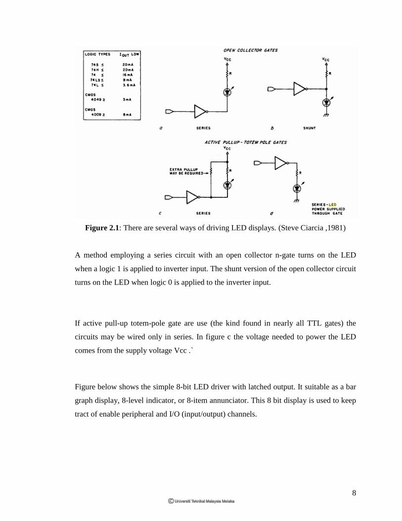
Figure 2.1: There are several ways of driving LED displays. (Steve Ciarcia ,1981)
A method employing a series circuit with an open collector n-gate turns on the LED
when a logic 1 is applied to inverter input. The shunt version of the open collector circuit
turns on the LED when logic 0 is applied to the inverter input.
If active pull-up totem-pole gate are use (the kind found in nearly all TTL gates) the
circuits may be wired only in series. In figure c the voltage needed to power the LED
comes from the supply voltage Vcc .`
Figure below shows the simple 8-bit LED driver with latched output. It suitable as a bar
graph display, 8-level indicator, or 8-item annunciator. This 8 bit display is used to keep
tract of enable peripheral and I/O (input/output) channels.

9
Figure 2.2: A simple 8-bit latched-output LED display, suitable for use in computer
controlled bar graph or 8-level indicator. (Steve Ciarcia ,1981)
2.4 Larger LED display Have Be Multiplexed
The 8 Led of course can be expanded to 64 by multiplying this same circuit 8-fold.
When an average current of 15 mA for each LED and 100 mA for each 74100 dual 4-bit
latch, the grand total to run it is slightly under 2A at 5V.This fact, and the necessary of
having 64 resistors as well, leads us to consider some other means of driving the LED.
The logical alternative to continuous operation is time-multiplexed operation. For an
LED with a 20 mA continuous current rating, this means should raise the peak current
(lpk) and reduce the duty cycle. If the duty cycle were 25%,the 4 Led could be
multiplexed through the same driver, and all would appear to operate continuously.
The more LED in the loop, the lower duty cycle. To maintain the same brightness, the
current is reused again to produce a reasonable average current. It reaches a point of
diminishing returns when the duty cycles becomes so low that the peak current required
to maintain a sufficient average current burns out the LED due to excessive power
dissipation. For pulse application, a curve of maximum peak current, pulse width, and
repetition rate can be used to determine the maximum recommended operating
condition. Figure illustrates a typical curve for a T-1(3/4) LED. It is determined by

10
comparing peak and average junction temperatures during strobes operation, and
maintaining a limit equivalent to the maximum allowable DC condition. At any
specified repetition rate, the relation ship between maximum current and pulse width is
shown. For example 5 LEDS were to be multiplexed and brightness maintained
equivalent to a 10mA continuous current each would have to be pulsed for 1 ms 100
times a second with a peak current of 100mA.
Figure 2.3 : A typical curve for a T-1(3/4) LED showing the relationship between
maximum current and pulse width for special pulse rates.( Steve Ciarcia ,1981)
Figure shows a simple 4 by 4 LED matrix which demonstrates this concept. It also
serves to point out some of the limitations of the bare-bones approach. A latched 8-bit
parallel output port is all that is necessary to run this display. Four bit defines the column
and 4 bits define the row. Multiplexing is done in software.

11
Figure 2.4: A simple 4 by 4 LED matrix which is software driven.( Steve Ciarcia ,1981)
A 4 by 4 display was too low in resolution, and while a 5 by 7 display allowed ASC11
alpha numeric displays, it was also a bit limited. Considering the hardware techniques
employed and relative indifference to refresh considerations on 8 by 16 displays.