Universal Side-of-Pole Mount UNI-SP/02 · UNI-SP/02 UNI-SP/02 April 2008 ... Solar Mounting...
13
Installation Manual Universal Side-of-Pole Mount UNI-SP/02 UNI-SP/02 April 2008 www.IronRidge.com © 2008 IronRidge, Inc. All Rights Reserved Solar Mounting Solutions Version 2.0
Transcript of Universal Side-of-Pole Mount UNI-SP/02 · UNI-SP/02 UNI-SP/02 April 2008 ... Solar Mounting...

Installation Manual Universal Side-of-Pole Mount
UNI-SP/02
UNI-SP/02 April 2008 www.IronRidge.com © 2008 IronRidge, Inc. All Rights Reserved
S o l a r M o u n t i n g S o l u t i o n s
Version 2.0

IronRidge ☀ 2 9 1 S h e l l L n . ☀ Wi l l i t s , C A 9 5 4 9 0 ☀ ( 7 0 7 ) 4 5 9 - 9 5 2 3 ☀ Fa x ( 7 0 7 ) 4 5 9 - 1 8 3 3 ☀ w w w. I r o n R i d g e . c o m
2 | Universal Side-of-Pole Mount UNI-SP/02 Installation Guide
IntroductionThe Universal Side-of-Pole Mount UNI-SP/02 is a very sturdy and straightforward pole mounting solution for small area solar photo voltaic (PV) needs. With its user-adjustable angle settings, it can support installations in a wide range of locations.
In addition, the UNI-SP/02 supports:
Up to two PV panels with a combined width of up to 45 inches. ♦
Pole diameters from 2.0 inches to 4.5-inches. ♦
1. Installer ResponsibilityThe installer is solely responsible for:
Complying with all applicable local or national building codes, including any that may supersede this ♦manual
Ensuring that IronRidge and other products are appropriate for the particular installation and the installa- ♦tion environment
Ensuring that the selected mount can support the array under live load conditions ♦
Using only IronRidge parts and installer-supplied parts as specified by IronRidge. Substitution parts may ♦void the warranty
Ensuring safe installation of all electrical aspects of the PV array. ♦
2. Customer SupportIronRidge makes every effort to ensure your mounting kit is easy to install. If you need assistance at any point with your installation or have suggestions on how we can improve your experience, call IronRidge customer support: (800) 227-9523
3. Tools Required For AssemblyThe following tools are required to assemble the Universal Side-of-Pole Mount:
Tool Use for
Wrenches
Open-end wrench, Box-end wrench, or 3/8” or greater socket drive with sockets to sup-port the following size hex heads:
5/16” ♦
1/4” ♦
5/16-18 cap-end screws ♦
5/16-18 bolts ♦
1/4-20 cap-end screws ♦
1/4-20 bolts ♦
Cap-end screws on hose clamps ♦
Screwdriver
Slotted, 1/4” Cap-end screws on hose clamps ♦

IronRidge ☀ 2 9 1 S h e l l L n . ☀ Wi l l i t s , C A 9 5 4 9 0 ☀ ( 7 0 7 ) 4 5 9 - 9 5 2 3 ☀ Fa x ( 7 0 7 ) 4 5 9 - 1 8 3 3 ☀ w w w. I r o n R i d g e . c o m
3 | Universal Side-of-Pole Mount UNI-SP/02 Installation Guide
4. Component ListThe Universal Side-of-Pole Mount UNI-SP/02 kit contains the following parts:
Bucket (51-3517-200) x2
Attaches to the pole with the hose clamps, providing the link between the pole and the module/rail sup-port assembly
Hose Clamps (27-5000-010) x4Attach to the pole, holding the Bucket. These hose clamps are compatible with poles ranging from 2.0 inches to 4.5 inches
Rails (51-0545-002) x2
Attach directly to the back of the module
Clips left (51-3517-243) x2 and right (51-3517-244) x2Hold the panel rails, allowing adjustment of the panel angle
Support Rails inner (51-0519-000) x2 and outer (51-0519-001) x2Attach to the lower bucket, supporting the lower edge of the panel

IronRidge ☀ 2 9 1 S h e l l L n . ☀ Wi l l i t s , C A 9 5 4 9 0 ☀ ( 7 0 7 ) 4 5 9 - 9 5 2 3 ☀ Fa x ( 7 0 7 ) 4 5 9 - 1 8 3 3 ☀ w w w. I r o n R i d g e . c o m
4 | Universal Side-of-Pole Mount UNI-SP/02 Installation Guide
Part Qty Part Number
1/4 x 3/4” Kit 2 29-5001-000
1/4-20 x 3/4” SS hex-cap bolt 8 23-2520-050
1/4 flat washer, SS 8 25-2502-000
1/4 split lock washer, SS 8 24-2501-000
1/4-20 fin hex nut, SS 8 24-2520-440
5/16 x 3/4” Kit 1 29-5004-010
5/16-18 x 3/4” SS hex-cap bolt 16 23-3118-021
5/16 flat washer, SS 32 25-3102-000
5/16 split lock washer, SS 16 25-3101-000
5/16 hex nut, SS 16 25-3118-440
5/16 x 3/4” Kit 1 29-5006-001
5/16-18 x 3/4” SS hex-cap bolt 6 23-3118-021
5/16 flat washer, SS 12 25-3102-000
5/16 split lock washer, SS 6 25-3101-000
5/16 hex nut, SS 6 25-3118-440
5/16 and 1/4 x 3/4” spare hardware kit 1 29-5002-000
5. Assembly
Step 1 - measuring the distance between mounting holes on the PV module
Parts Required Qty Part Number
PV Module 1 or 2 User-supplied
Lay the modules face down 1. on a protected surface in the appropriate orientation. Leave an inch or two between the panels.

IronRidge ☀ 2 9 1 S h e l l L n . ☀ Wi l l i t s , C A 9 5 4 9 0 ☀ ( 7 0 7 ) 4 5 9 - 9 5 2 3 ☀ Fa x ( 7 0 7 ) 4 5 9 - 1 8 3 3 ☀ w w w. I r o n R i d g e . c o m
5 | Universal Side-of-Pole Mount UNI-SP/02 Installation Guide
Measure the distance be-2. tween the inside mounting holes on the back of the PV module as shown and make a note of it.
Step 2 - mounting the rail supports on the PV module
Parts Required Qty Part Number
Rails 2 51-0545-002
1/4-20 x 3/4” SS hex-cap bolt 8 23-2520-050
1/4 flat washer, SS 8 25-2502-000
1/4 split lock washer, SS 8 24-2501-000
1/4 hex nut, SS 8 24-2520-440

IronRidge ☀ 2 9 1 S h e l l L n . ☀ Wi l l i t s , C A 9 5 4 9 0 ☀ ( 7 0 7 ) 4 5 9 - 9 5 2 3 ☀ Fa x ( 7 0 7 ) 4 5 9 - 1 8 3 3 ☀ w w w. I r o n R i d g e . c o m
6 | Universal Side-of-Pole Mount UNI-SP/02 Installation Guide
Do one of the following:1.
If the distance between the ♦PV module mounting holes is less than 26.9”, place the rails on the back of the panel so the lip of the rail containing the module mounting holes is facing towards the center of the module.
If the distance between ♦the PV module mounting holes is 26.9” or more, place the rails on the back of the panel so the lip of the rail containing the module mounting holes is facing toward the outside edges of the module.
Secure the rails with a bolt, 2. lock washer and hex nut in each of the PV mounting holes (4 on each panel). Tighten the bolts to 7 ft-lbs.
Step 3 - attaching the clips to the rails
Parts Required Qty Part Number
Clip, left end 1 51-3517-243
Clip, right end 1 51-3517-244
5/16-18 x 3/4” SS hex-cap bolt 4 23-3118-021
5/16 flat washer, SS 8 25-3102-000
5/16 split lock washer, SS 4 25-3101-000
5/16 hex nut, SS 4 25-3118-440
IronRidge ☀ 2 9 1 S h e l l L n . ☀ Wi l l i t s , C A 9 5 4 9 0 ☀ ( 7 0 7 ) 4 5 9 - 9 5 2 3 ☀ Fa x ( 7 0 7 ) 4 5 9 - 1 8 3 3 ☀ w w w. I r o n R i d g e . c o m
7 | Universal Side-of-Pole Mount UNI-SP/02 Installation Guide
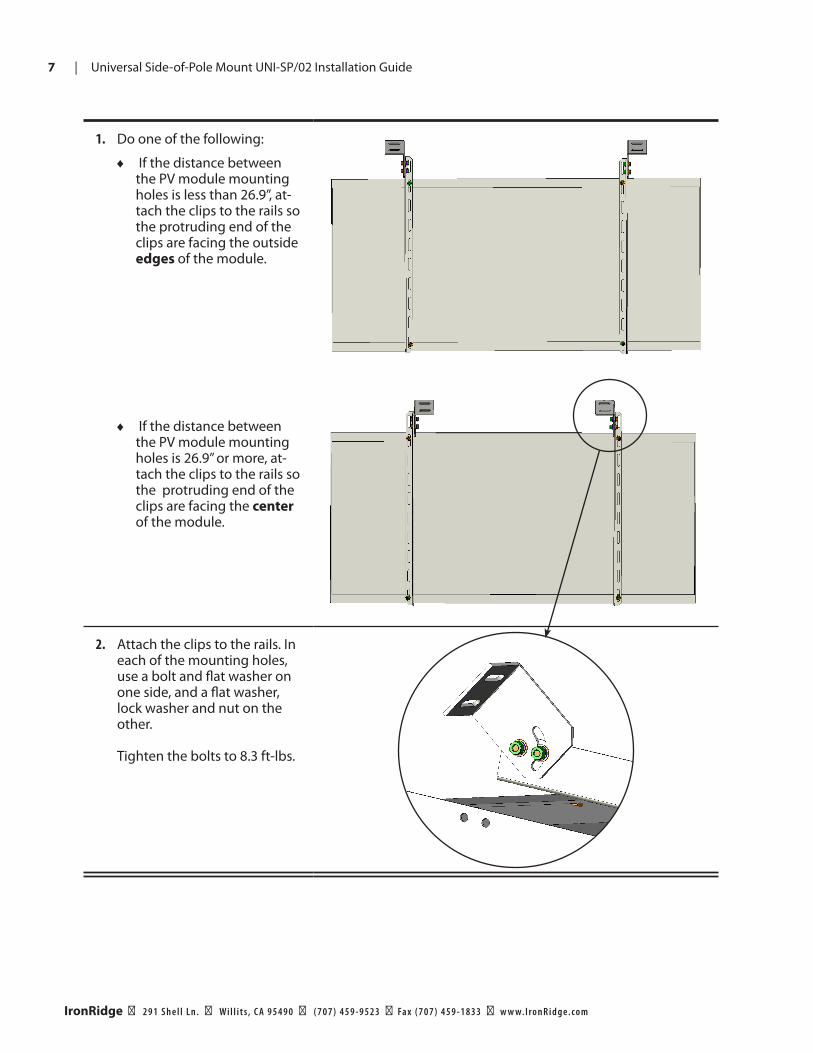
Do one of the following:1.
If the distance between ♦the PV module mounting holes is less than 26.9”, at-tach the clips to the rails so the protruding end of the clips are facing the outside edges of the module.
If the distance between ♦the PV module mounting holes is 26.9” or more, at-tach the clips to the rails so the protruding end of the clips are facing the center of the module.
Attach the clips to the rails. In 2. each of the mounting holes, use a bolt and flat washer on one side, and a flat washer, lock washer and nut on the other. Tighten the bolts to 8.3 ft-lbs.

IronRidge ☀ 2 9 1 S h e l l L n . ☀ Wi l l i t s , C A 9 5 4 9 0 ☀ ( 7 0 7 ) 4 5 9 - 9 5 2 3 ☀ Fa x ( 7 0 7 ) 4 5 9 - 1 8 3 3 ☀ w w w. I r o n R i d g e . c o m
8 | Universal Side-of-Pole Mount UNI-SP/02 Installation Guide
Step 4 - assembling the support rails
Parts Required Qty Part Number
Support Rail, inner 2 51-0519-000
Support Rail, outer 2 51-0519-001
5/16-18 x 3/4” SS hex-cap bolt 4 23-3118-021
5/16 flat washer, SS 8 25-3102-000
5/16 split lock washer, SS 4 25-3101-000
5/16 hex nut, SS 4 25-3118-440
Line up an inner an outer support rail as 1. shown so that two of the holes in the rails line up.
Bolt the rails together using a flat washer 2. on both sides, with a lock washer under the nut. Tighten the bolts to 8.3 ft-lbs.
Repeat with the second set of support 3. rails.

IronRidge ☀ 2 9 1 S h e l l L n . ☀ Wi l l i t s , C A 9 5 4 9 0 ☀ ( 7 0 7 ) 4 5 9 - 9 5 2 3 ☀ Fa x ( 7 0 7 ) 4 5 9 - 1 8 3 3 ☀ w w w. I r o n R i d g e . c o m
9 | Universal Side-of-Pole Mount UNI-SP/02 Installation Guide
Step 5 - attaching the buckets to the pole
Parts Required Qty Part Number
Hose Clamp 4 27-5000-010
Bucket 2 51-3517-200
Thread a hose clamp through each of the 1. sets of narrow center holes in the buckets.
Place the bucket assemblies at the de-2. sired location on the pole. Start with the buckets about 36 inches apart. The spac-ing can be adjusted later. I These hose clamps are only compat-ible with poles ranging from 2.0” to 4.5”
Once the hose clamps are in the desired 3. position, tighten the hose clamp screws to 70 inch-lbs.

IronRidge ☀ 2 9 1 S h e l l L n . ☀ Wi l l i t s , C A 9 5 4 9 0 ☀ ( 7 0 7 ) 4 5 9 - 9 5 2 3 ☀ Fa x ( 7 0 7 ) 4 5 9 - 1 8 3 3 ☀ w w w. I r o n R i d g e . c o m
10 | Universal Side-of-Pole Mount UNI-SP/02 Installation Guide
Step 6 - mounting the PV assembly on the pole
Parts Required Qty Part Number
1/4-20 x 3/4” SS hex-cap bolt 4 23-2520-050
1/4 flat washer, SS 8 25-2502-000
1/4 split lock washer, SS 4 24-2501-000
1/4 hex nut, SS 4 24-2520-440
Place the PV module assembly 1. so the holes on the clips line up with holes in the inside of the bucket. Note: depending on the size of the panels you started with, your assembly may look dif-ferent than this picture, with the clips and rails facing in the opposite direction.
Bolt the clips to the bucket 2. using flat washers with a lock washer under the nut. Tighten the bolts to 8.3 ft-lbs.

IronRidge ☀ 2 9 1 S h e l l L n . ☀ Wi l l i t s , C A 9 5 4 9 0 ☀ ( 7 0 7 ) 4 5 9 - 9 5 2 3 ☀ Fa x ( 7 0 7 ) 4 5 9 - 1 8 3 3 ☀ w w w. I r o n R i d g e . c o m
11 | Universal Side-of-Pole Mount UNI-SP/02 Installation Guide
Step 7 - attaching the support rails
Parts Required Qty Part Number
Clip, left end 1 51-3517-243
Clip, right end 1 51-3517-244
1/4-20 x 3/4” SS hex-cap bolt 8 23-2520-050
1/4 flat washer, SS 16 25-2502-000
1/4 split lock washer, SS 8 24-2501-000
1/4 hex nut, SS 8 24-2520-440
Bolt the remaining two clips 1. to the lower bucket using flat washers with a lock washer under the nut.
Tighten the bolts to 8.3 ft-lbs.2.

IronRidge ☀ 2 9 1 S h e l l L n . ☀ Wi l l i t s , C A 9 5 4 9 0 ☀ ( 7 0 7 ) 4 5 9 - 9 5 2 3 ☀ Fa x ( 7 0 7 ) 4 5 9 - 1 8 3 3 ☀ w w w. I r o n R i d g e . c o m
12 | Universal Side-of-Pole Mount UNI-SP/02 Installation Guide
For each of the two support 3. rails, bolt one end of the rail to the corresponding bucket, using flat washers with a lock washer under the nut.
Bolt the other end of each 4. support rail to the end of the corresponding panel mount-ing rail, using flat washers with a lock washer under the nut.
Adjust the panel angle as 5. desired, by:
Moving the lower bucket ♦up or down
Lengthening or shorten- ♦ing the panel support rails by lining up two alternate holes
Changing the hole where ♦the support rail connects to the panel rail
Once the adjustments are 6. complete, tighten all 1/4” hardware to 8.3 ft-lbs.

IronRidge ☀ 2 9 1 S h e l l L n . ☀ Wi l l i t s , C A 9 5 4 9 0 ☀ ( 7 0 7 ) 4 5 9 - 9 5 2 3 ☀ Fa x ( 7 0 7 ) 4 5 9 - 1 8 3 3 ☀ w w w. I r o n R i d g e . c o m
13 | Universal Side-of-Pole Mount UNI-SP/02 Installation Guide13 | Universal Side-of-Pole Mount UNI-SP/02 Installation Guide
IronRidge 10-Year WarrantyTerms and Conditions
IronRidge warrants each Mounting Structure to be free from defects in materials and workmanship for ten (10) years from the date of first purchase (“Warranty Period”), when installed properly and used for the purpose for which it is designed, except for the finish, which shall be free from visible peeling, or cracking or chalking under normal atmospheric conditions for a period of three (3) years, from the earlier of 1) the date the installation of the Product is completed, or 2) 30 days after the purchase of the Product by the original Purchaser (“Finish Warranty”). The Finish Warranty does not apply to any foreign residue deposited on the finish. All installations in corrosive atmospheric conditions are excluded. The Finish Warranty is VOID if the practices specified by AAMA 609 & 610-02 – “Cleaning and Maintenance for Architecturally Finished Aluminum” (www.aamanet.org) are not followed by Purchaser for IronRidge’s aluminum based products.
The warranty covers the replacement cost of parts to repair the product to proper working condition. Transportation and incidental costs associated with warranty items are not reimbursable. The warranty does not cover normal wear, or damage resulting from misuse, abuse, improper installation, negligence, or accident. The warranty does not cover any defect that has not been reported in writing to IronRidge within ten (10) days after discovery of such defect. Furthermore, it does not cover units that have been altered, modified or repaired without written authorization from the manufacturer or its authorized representative, or units used in a manner or for a purpose other than that specified by the manufacturer. IronRidge’s entire liability and Purchaser exclusive remedy, whether in contract, tort or otherwise, for any claim related to or arising out of breach of the warranty covering the Mounting Structures shall be correction of defects by repair, replacement, or credit, at IronRidge’s discretion. Refurbished Mounting Structures may be used to repair or replace the Mounting Structures.
IronRidge shall have no liability for any injuries or damages to persons or property resulting from any cause, whatsoever, or any claims or demands brought against IronRidge by Purchaser, any employee of Purchaser, client of Purchaser, end-user of the Product or other party, even if IronRidge has been advised of the possibility of such claims or demands (collectively, “Third Party Claims”). This limitation applies to all materials provided by IronRidge during and after the Warranty Period.