
Universal Serial Bus Specification Revision 1.1esd.cs.ucr.edu/webres/usb11.pdf · Universal Serial...
327
Universal Serial Bus Specification Compaq Intel Microsoft NEC Revision 1.1 September 23, 1998
Transcript of Universal Serial Bus Specification Revision 1.1esd.cs.ucr.edu/webres/usb11.pdf · Universal Serial...

Universal Serial BusSpecification
Compaq
Intel
Microsoft
NEC
Revision 1.1September 23, 1998

Universal Serial Bus Specification Revision 1.1
ii
Scope of this RevisionThe 1.1 revision of the specification is intended for product design. Every attempt has been made to ensure aconsistent and implementable specification. Implementations should ensure compliance with this revision.
Revision History
Revision Issue Date Comments
0.7 November 11, 1994 Supersedes 0.6e.
0.8 December 30, 1994 Revisions to Chapters 3-8, 10, and 11. Addedappendixes.
0.9 April 13, 1995 Revisions to all the chapters.
0.99 August 25, 1995 Revisions to all the chapters.
1.0 FDR November 13, 1995 Revisions to Chapters 1, 2, 5-11.
1.0 January 15, 1996 Edits to Chapters 5, 6, 7, 8, 9, 10, and 11 forconsistency.
1.1 September 23, 1998 Updates to all chapters to fix problems identified.
Universal Serial Bus SpecificationCopyright © 1998, Compaq Computer Corporation,
Intel Corporation, Microsoft Corporation, NEC Corporation.All rights reserved.
INTELLECTUAL PROPERTY DISCLAIMERTHIS SPECIFICATION IS PROVIDED “AS IS” WITH NO WARRANTIES WHATSOEVER INCLUDINGANY WARRANTY OF MERCHANTABILITY, FITNESS FOR ANY PARTICULAR PURPOSE, OR ANYWARRANTY OTHERWISE ARISING OUT OF ANY PROPOSAL, SPECIFICATION, OR SAMPLE.A LICENSE IS HEREBY GRANTED TO REPRODUCE AND DISTRIBUTE THIS SPECIFICATION FORINTERNAL USE ONLY. NO OTHER LICENSE, EXPRESS OR IMPLIED, BY ESTOPPEL OROTHERWISE, TO ANY OTHER INTELLECTUAL PROPERTY RIGHTS IS GRANTED OR INTENDEDHEREBY.AUTHORS OF THIS SPECIFICATION DISCLAIM ALL LIABILITY, INCLUDING LIABILITY FORINFRINGEMENT OF PROPRIETARY RIGHTS, RELATING TO IMPLEMENTATION OFINFORMATION IN THIS SPECIFICATION. AUTHORS OF THIS SPECIFICATION ALSO DO NOTWARRANT OR REPRESENT THAT SUCH IMPLEMENTATION(S) WILL NOT INFRINGE SUCHRIGHTS.
GeoPort and Apple Desktop Bus are trademarks of Apple Computer, Inc.Windows and Windows NT are trademarks and Microsoft and Win32 are registered trademarks of Microsoft Corporation.IBM, PS/2, and Micro Channel are registered trademarks of International Business Machines Corporation.AT&T is a registered trademark of American Telephone and Telegraph Company.Compaq is a registered trademark of Compaq Computer Corporation.UNIX is a registered trademark of UNIX System Laboratories.I2C is a trademark of Phillips Semiconductors.DEC is a trademark of Digital Equipment Corporation.All other product names are trademarks, registered trademarks, or servicemarks of their respective owners.
Please send comments via electronic mail to [email protected] industry information, refer to the USB Implementers Forum web page at http://www.usb.org

Universal Serial Bus Specification Revision 1.1
iii
Contents
CHAPTER 1 INTRODUCTION ................................................................................. 1
1.1 Motivation ...............................................................................................................................................1
1.2 Objective of the Specification ................................................................................................................1
1.3 Scope of the Document ...........................................................................................................................2
1.4 Document Organization.........................................................................................................................2
CHAPTER 2 TERMS AND ABBREVIATIONS.......................................................... 3
CHAPTER 3 BACKGROUND.................................................................................. 11
3.1 Goals for the Universal Serial Bus ......................................................................................................11
3.2 Taxonomy of Application Space..........................................................................................................12
3.3 Feature List ...........................................................................................................................................12
CHAPTER 4 ARCHITECTURAL OVERVIEW........................................................ 15
4.1 USB System Description ......................................................................................................................154.1.1 Bus Topology ..................................................................................................................................16
4.2 Physical Interface .................................................................................................................................174.2.1 Electrical .........................................................................................................................................174.2.2 Mechanical ......................................................................................................................................17
4.3 Power.....................................................................................................................................................184.3.1 Power Distribution ..........................................................................................................................184.3.2 Power Management.........................................................................................................................18
4.4 Bus Protocol ..........................................................................................................................................18
4.5 Robustness.............................................................................................................................................194.5.1 Error Detection................................................................................................................................194.5.2 Error Handling.................................................................................................................................19
4.6 System Configuration...........................................................................................................................194.6.1 Attachment of USB Devices ...........................................................................................................194.6.2 Removal of USB Devices................................................................................................................204.6.3 Bus Enumeration .............................................................................................................................20
4.7 Data Flow Types ...................................................................................................................................204.7.1 Control Transfers.............................................................................................................................20

Universal Serial Bus Specification Revision 1.1
iv
4.7.2 Bulk Transfers.................................................................................................................................204.7.3 Interrupt Transfers...........................................................................................................................214.7.4 Isochronous Transfers .....................................................................................................................214.7.5 Allocating USB Bandwidth.............................................................................................................21
4.8 USB Devices ..........................................................................................................................................214.8.1 Device Characterizations.................................................................................................................214.8.2 Device Descriptions ........................................................................................................................22
4.9 USB Host: Hardware and Software...................................................................................................24
4.10 Architectural Extensions .....................................................................................................................24
CHAPTER 5 USB DATA FLOW MODEL................................................................ 25
5.1 Implementer Viewpoints......................................................................................................................25
5.2 Bus Topology ........................................................................................................................................275.2.1 USB Host ........................................................................................................................................275.2.2 USB Devices ...................................................................................................................................285.2.3 Physical Bus Topology....................................................................................................................295.2.4 Logical Bus Topology.....................................................................................................................305.2.5 Client Software-to-function Relationship........................................................................................30
5.3 USB Communication Flow ..................................................................................................................315.3.1 Device Endpoints ............................................................................................................................325.3.2 Pipes................................................................................................................................................33
5.4 Transfer Types......................................................................................................................................35
5.5 Control Transfers.................................................................................................................................365.5.1 Control Transfer Data Format .........................................................................................................365.5.2 Control Transfer Direction ..............................................................................................................375.5.3 Control Transfer Packet Size Constraints........................................................................................375.5.4 Control Transfer Bus Access Constraints........................................................................................385.5.5 Control Transfer Data Sequences....................................................................................................40
5.6 Isochronous Transfers .........................................................................................................................415.6.1 Isochronous Transfer Data Format..................................................................................................415.6.2 Isochronous Transfer Direction.......................................................................................................415.6.3 Isochronous Transfer Packet Size Constraints ................................................................................415.6.4 Isochronous Transfer Bus Access Constraints ................................................................................425.6.5 Isochronous Transfer Data Sequences.............................................................................................43
5.7 Interrupt Transfers ..............................................................................................................................435.7.1 Interrupt Transfer Data Format .......................................................................................................435.7.2 Interrupt Transfer Direction ............................................................................................................435.7.3 Interrupt Transfer Packet Size Constraints......................................................................................435.7.4 Interrupt Transfer Bus Access Constraints......................................................................................445.7.5 Interrupt Transfer Data Sequences ..................................................................................................46
5.8 Bulk Transfers ......................................................................................................................................465.8.1 Bulk Transfer Data Format .............................................................................................................475.8.2 Bulk Transfer Direction ..................................................................................................................475.8.3 Bulk Transfer Packet Size Constraints............................................................................................47

Universal Serial Bus Specification Revision 1.1
v
5.8.4 Bulk Transfer Bus Access Constraints ............................................................................................475.8.5 Bulk Transfer Data Sequences ........................................................................................................48
5.9 Bus Access for Transfers......................................................................................................................495.9.1 Transfer Management......................................................................................................................495.9.2 Transaction Tracking.......................................................................................................................525.9.3 Calculating Bus Transaction Times.................................................................................................545.9.4 Calculating Buffer Sizes in Functions and Software.......................................................................555.9.5 Bus Bandwidth Reclamation ...........................................................................................................55
5.10 Special Considerations for Isochronous Transfers............................................................................555.10.1 Example Non-USB Isochronous Application..................................................................................565.10.2 USB Clock Model ...........................................................................................................................595.10.3 Clock Synchronization ....................................................................................................................615.10.4 Isochronous Devices........................................................................................................................615.10.5 Data Prebuffering ............................................................................................................................695.10.6 SOF Tracking ..................................................................................................................................705.10.7 Error Handling.................................................................................................................................705.10.8 Buffering for Rate Matching ...........................................................................................................71
CHAPTER 6 MECHANICAL.................................................................................... 73
6.1 Architectural Overview........................................................................................................................73
6.2 Keyed Connector Protocol...................................................................................................................73
6.3 Cable......................................................................................................................................................74
6.4 Cable Assembly.....................................................................................................................................746.4.1 Detachable Cable Assemblies .........................................................................................................746.4.2 Full-speed Captive Cable Assemblies .............................................................................................766.4.3 Low-speed Captive Cable Assemblies ............................................................................................786.4.4 Prohibited Cable Assemblies...........................................................................................................80
6.5 Connector Mechanical Configuration and Material Requirements ................................................806.5.1 USB Icon Location..........................................................................................................................816.5.2 USB Connector Termination Data ..................................................................................................826.5.3 Series “A” and Series “B” Receptacles ...........................................................................................826.5.4 Series “A” and Series “B” Plugs .....................................................................................................86
6.6 Cable Mechanical Configuration and Material Requirements ........................................................906.6.1 Description ......................................................................................................................................906.6.2 Construction ....................................................................................................................................916.6.3 Electrical Characteristics.................................................................................................................936.6.4 Cable Environmental Characteristics ..............................................................................................936.6.5 Listing .............................................................................................................................................94
6.7 Electrical, Mechanical and Environmental Compliance Standards ................................................946.7.1 Applicable Documents ..................................................................................................................102
6.8 USB Grounding ..................................................................................................................................102
6.9 PCB Reference Drawings...................................................................................................................102

Universal Serial Bus Specification Revision 1.1
vi
CHAPTER 7 ELECTRICAL................................................................................... 107
7.1 Signaling..............................................................................................................................................1077.1.1 USB Driver Characteristics...........................................................................................................1077.1.2 Data Signal Rise and Fall ..............................................................................................................1107.1.3 Cable Skew....................................................................................................................................1127.1.4 Receiver Characteristics................................................................................................................1127.1.5 Device Speed Identification ..........................................................................................................1137.1.6 Input Characteristics......................................................................................................................1147.1.7 Signaling Levels............................................................................................................................1157.1.8 Data Encoding/Decoding ..............................................................................................................1237.1.9 Bit Stuffing....................................................................................................................................1247.1.10 Sync Pattern ..................................................................................................................................1267.1.11 Data Signaling Rate.......................................................................................................................1267.1.12 Frame Interval and Frame Interval Adjustment ............................................................................1267.1.13 Data Source Signaling...................................................................................................................1277.1.14 Hub Signaling Timings .................................................................................................................1287.1.15 Receiver Data Jitter .......................................................................................................................1307.1.16 Cable Delay...................................................................................................................................1327.1.17 Cable Attenuation..........................................................................................................................1337.1.18 Bus Turn-around Time and Inter-packet Delay.............................................................................1337.1.19 Maximum End-to-end Signal Delay..............................................................................................133
7.2 Power Distribution .............................................................................................................................1347.2.1 Classes of Devices.........................................................................................................................1347.2.2 Voltage Drop Budget ....................................................................................................................1387.2.3 Power Control During Suspend/Resume.......................................................................................1397.2.4 Dynamic Attach and Detach..........................................................................................................140
7.3 Physical Layer ....................................................................................................................................1417.3.1 Regulatory Requirements..............................................................................................................1427.3.2 Bus Timing/Electrical Characteristics...........................................................................................1427.3.3 Timing Waveforms .......................................................................................................................151
CHAPTER 8 PROTOCOL LAYER ........................................................................ 155
8.1 Bit Ordering........................................................................................................................................155
8.2 SYNC Field .........................................................................................................................................155
8.3 Packet Field Formats .........................................................................................................................1558.3.1 Packet Identifier Field ...................................................................................................................1558.3.2 Address Fields...............................................................................................................................1568.3.3 Frame Number Field .....................................................................................................................1578.3.4 Data Field......................................................................................................................................1578.3.5 Cyclic Redundancy Checks...........................................................................................................158
8.4 Packet Formats...................................................................................................................................1588.4.1 Token Packets ...............................................................................................................................1598.4.2 Start-of-Frame Packets..................................................................................................................1598.4.3 Data Packets..................................................................................................................................1608.4.4 Handshake Packets........................................................................................................................1608.4.5 Handshake Responses ...................................................................................................................161

Universal Serial Bus Specification Revision 1.1
vii
8.5 Transaction Formats ..........................................................................................................................1628.5.1 Bulk Transactions..........................................................................................................................1638.5.2 Control Transfers...........................................................................................................................1648.5.3 Interrupt Transactions....................................................................................................................1678.5.4 Isochronous Transactions ..............................................................................................................168
8.6 Data Toggle Synchronization and Retry ..........................................................................................1688.6.1 Initialization via SETUP Token ....................................................................................................1698.6.2 Successful Data Transactions ........................................................................................................1698.6.3 Data Corrupted or Not Accepted...................................................................................................1708.6.4 Corrupted ACK Handshake...........................................................................................................1708.6.5 Low-speed Transactions................................................................................................................171
8.7 Error Detection and Recovery...........................................................................................................1728.7.1 Packet Error Categories.................................................................................................................1728.7.2 Bus Turn-around Timing...............................................................................................................1728.7.3 False EOPs ....................................................................................................................................1738.7.4 Babble and Loss of Activity Recovery..........................................................................................174
CHAPTER 9 USB DEVICE FRAMEWORK........................................................... 175
9.1 USB Device States...............................................................................................................................1759.1.1 Visible Device States.....................................................................................................................1759.1.2 Bus Enumeration ...........................................................................................................................179
9.2 Generic USB Device Operations .......................................................................................................1809.2.1 Dynamic Attachment and Removal...............................................................................................1809.2.2 Address Assignment......................................................................................................................1809.2.3 Configuration ................................................................................................................................1809.2.4 Data Transfer.................................................................................................................................1819.2.5 Power Management.......................................................................................................................1819.2.6 Request Processing........................................................................................................................1819.2.7 Request Error.................................................................................................................................182
9.3 USB Device Requests..........................................................................................................................1839.3.1 bmRequestType.............................................................................................................................1839.3.2 bRequest ........................................................................................................................................1849.3.3 wValue ..........................................................................................................................................1849.3.4 wIndex...........................................................................................................................................1849.3.5 wLength.........................................................................................................................................184
9.4 Standard Device Requests..................................................................................................................1859.4.1 Clear Feature .................................................................................................................................1889.4.2 Get Configuration..........................................................................................................................1899.4.3 Get Descriptor ...............................................................................................................................1899.4.4 Get Interface..................................................................................................................................1909.4.5 Get Status ......................................................................................................................................1909.4.6 Set Address....................................................................................................................................1929.4.7 Set Configuration ..........................................................................................................................1939.4.8 Set Descriptor................................................................................................................................1939.4.9 Set Feature.....................................................................................................................................1949.4.10 Set Interface...................................................................................................................................1959.4.11 Synch Frame..................................................................................................................................195
9.5 Descriptors ..........................................................................................................................................196

Universal Serial Bus Specification Revision 1.1
viii
9.6 Standard USB Descriptor Definitions...............................................................................................1969.6.1 Device ...........................................................................................................................................1969.6.2 Configuration ................................................................................................................................1999.6.3 Interface ........................................................................................................................................2019.6.4 Endpoint ........................................................................................................................................2039.6.5 String.............................................................................................................................................204
9.7 Device Class Definitions.....................................................................................................................2059.7.1 Descriptors ....................................................................................................................................2059.7.2 Interface(s) and Endpoint Usage ...................................................................................................2059.7.3 Requests ........................................................................................................................................206
CHAPTER 10 USB HOST: HARDWARE AND SOFTWARE .............................. 207
10.1 Overview of the USB Host .................................................................................................................20710.1.1 Overview.......................................................................................................................................20710.1.2 Control Mechanisms .....................................................................................................................21010.1.3 Data Flow......................................................................................................................................21010.1.4 Collecting Status and Activity Statistics .......................................................................................21110.1.5 Electrical Interface Considerations ...............................................................................................211
10.2 Host Controller Requirements ..........................................................................................................21110.2.1 State Handling...............................................................................................................................21210.2.2 Serializer/Deserializer ...................................................................................................................21210.2.3 Frame Generation..........................................................................................................................21210.2.4 Data Processing.............................................................................................................................21310.2.5 Protocol Engine.............................................................................................................................21310.2.6 Transmission Error Handling ........................................................................................................21310.2.7 Remote Wakeup ............................................................................................................................21410.2.8 Root Hub .......................................................................................................................................21410.2.9 Host System Interface ...................................................................................................................214
10.3 Overview of Software Mechanisms...................................................................................................21410.3.1 Device Configuration ....................................................................................................................21510.3.2 Resource Management ..................................................................................................................21710.3.3 Data Transfers ...............................................................................................................................21710.3.4 Common Data Definitions ............................................................................................................218
10.4 Host Controller Driver.......................................................................................................................218
10.5 Universal Serial Bus Driver...............................................................................................................21910.5.1 USBD Overview ...........................................................................................................................21910.5.2 USBD Command Mechanism Requirements................................................................................22110.5.3 USBD Pipe Mechanisms...............................................................................................................22310.5.4 Managing the USB via the USBD Mechanisms............................................................................22510.5.5 Passing USB Preboot Control to the Operating System................................................................227
10.6 Operating System Environment Guides...........................................................................................227
CHAPTER 11 HUB SPECIFICATION ................................................................... 229
11.1 Overview .............................................................................................................................................22911.1.1 Hub Architecture...........................................................................................................................23011.1.2 Hub Connectivity ..........................................................................................................................230

Universal Serial Bus Specification Revision 1.1
ix
11.2 Hub Frame Timer...............................................................................................................................23211.2.1 Frame Timer Synchronization.......................................................................................................23311.2.2 EOF1 and EOF2 Timing Points ....................................................................................................234
11.3 Host Behavior at End-of-Frame........................................................................................................23511.3.1 Latest Host Packet .........................................................................................................................23511.3.2 Packet Nullification.......................................................................................................................23511.3.3 Transaction Completion Prediction...............................................................................................236
11.4 Internal Port .......................................................................................................................................23711.4.1 Inactive..........................................................................................................................................23711.4.2 Suspend Delay...............................................................................................................................23711.4.3 Full Suspend (Fsus) .......................................................................................................................23711.4.4 Generate Resume (GResume) .......................................................................................................238
11.5 Downstream Ports ..............................................................................................................................23911.5.1 Downstream Port State Descriptions.............................................................................................24011.5.2 Disconnect Detect Timer...............................................................................................................243
11.6 Upstream Port.....................................................................................................................................24411.6.1 Receiver.........................................................................................................................................24411.6.2 Transmitter ....................................................................................................................................246
11.7 Hub Repeater......................................................................................................................................24911.7.1 Wait for Start of Packet from Upstream Port (WFSOPFU) ..........................................................25011.7.2 Wait for End of Packet from Upstream Port (WFEOPFU) ...........................................................25011.7.3 Wait for Start of Packet (WFSOP) ................................................................................................25111.7.4 Wait for End of Packet (WFEOP).................................................................................................251
11.8 Bus State Evaluation ..........................................................................................................................25111.8.1 Port Error.......................................................................................................................................25111.8.2 Speed Detection.............................................................................................................................25111.8.3 Collision ........................................................................................................................................25211.8.4 Full- versus Low-speed Behavior..................................................................................................252
11.9 Suspend and Resume..........................................................................................................................253
11.10 Hub Reset Behavior............................................................................................................................25411.10.1 Hub Receiving Reset on Upstream Port ........................................................................................254
11.11 Hub Port Power Control....................................................................................................................25511.11.1 Multiple Gangs..............................................................................................................................255
11.12 Hub I/O Buffer Requirements...........................................................................................................25611.12.1 Pull-up and Pull-down Resistors ...................................................................................................25611.12.2 Edge Rate Control .........................................................................................................................256
11.13 Hub Controller ...................................................................................................................................25611.13.1 Endpoint Organization ..................................................................................................................25711.13.2 Hub Information Architecture and Operation................................................................................25711.13.3 Port Change Information Processing.............................................................................................25911.13.4 Hub and Port Status Change Bitmap .............................................................................................25911.13.5 Over-current Reporting and Recovery ..........................................................................................260
11.14 Hub Configuration .............................................................................................................................261

Universal Serial Bus Specification Revision 1.1
x
11.15 Descriptors ..........................................................................................................................................26311.15.1 Standard Descriptors .....................................................................................................................26311.15.2 Class-specific Descriptors .............................................................................................................264
11.16 Requests...............................................................................................................................................26611.16.1 Standard Requests .........................................................................................................................26611.16.2 Class-specific Requests .................................................................................................................267
INDEX.................................................................................................................... 281

Universal Serial Bus Specification Revision 1.1
xi
Figures
Figure 3-1. Application Space Taxonomy...........................................................................................................12
Figure 4-1. Bus Topology....................................................................................................................................16
Figure 4-2. USB Cable.........................................................................................................................................17
Figure 4-3. A Typical Hub...................................................................................................................................22
Figure 4-4. Hubs in a Desktop Computer Environment ......................................................................................23
Figure 5-1. Simple USB Host/Device View ........................................................................................................25
Figure 5-2. USB Implementation Areas ..............................................................................................................26
Figure 5-3. Host Composition .............................................................................................................................27
Figure 5-4. Physical Device Composition ...........................................................................................................28
Figure 5-5. USB Physical Bus Topology.............................................................................................................29
Figure 5-6. USB Logical Bus Topology ..............................................................................................................30
Figure 5-7. Client Software-to-function Relationships........................................................................................30
Figure 5-8. USB Host/Device Detailed View......................................................................................................31
Figure 5-9. USB Communication Flow...............................................................................................................32
Figure 5-10. USB Information Conversion From Client Software to Bus...........................................................50
Figure 5-11. Transfers for Communication Flows...............................................................................................52
Figure 5-12. Arrangement of IRPs to Transactions/Frames ................................................................................53
Figure 5-13. Non-USB Isochronous Example .....................................................................................................57
Figure 5-14. USB Isochronous Application.........................................................................................................60
Figure 5-15. Example Source/Sink Connectivity ................................................................................................66
Figure 5-16. Data Prebuffering............................................................................................................................70
Figure 5-17. Packet and Buffer Size Formulas for Rate-Matched Isochronous Transfers...................................72
Figure 6-1. Keyed Connector Protocol ................................................................................................................73
Figure 6-2. USB Detachable Cable Assembly......................................................................................................75
Figure 6-3. USB Full-speed Hardwired Cable Assembly.....................................................................................77
Figure 6-4. USB Low-speed Hardwired Cable Assembly ....................................................................................79
Figure 6-5. USB Icon...........................................................................................................................................81
Figure 6-6. Typical USB Plug Orientation ...........................................................................................................81
Figure 6-7. USB Series "A" Receptacle Interface and Mating Drawing .............................................................83
Figure 6-8. USB Series "B" Recptacle Interface and Mating Drawing ...............................................................84
Figure 6-9. USB Series "A" Plug Interface Drawing...........................................................................................87
Figure 6-10. USB Series “B” Plug Interface Drawing.........................................................................................88
Figure 6-11. Typical Full-speed Cable Construction...........................................................................................90
Figure 6-12. Single Pin-Type Series "A" Receptacle ........................................................................................103

Universal Serial Bus Specification Revision 1.1
xii
Figure 6-13. Dual Pin-Type Series "A" Receptacle...........................................................................................104
Figure 6-14. Single Pin-Type Series "B" Receptacle ........................................................................................105
Figure 7-1. Maximum Input Waveforms for USB Signaling ............................................................................107
Figure 7-2. Example Full-speed CMOS Driver Circuit.....................................................................................108
Figure 7-3. Full-speed Buffer V/I Characteristics .............................................................................................109
Figure 7-4. Full-speed Signal Waveforms.........................................................................................................110
Figure 7-5. Low-speed Driver Signal Waveforms.............................................................................................110
Figure 7-6. Data Signal Rise and Fall Time ......................................................................................................111
Figure 7-7. Full-speed Load ..............................................................................................................................111
Figure 7-8. Low-speed Port Loads ....................................................................................................................112
Figure 7-9. Differential Input Sensitivity Range ...............................................................................................113
Figure 7-10. Full-speed Device Cable and Resistor Connections......................................................................113
Figure 7-11. Low-speed Device Cable and Resistor Connections.....................................................................114
Figure 7-12. Placement of Optional Edge Rate Control Capacitors ..................................................................115
Figure 7-13. Upstream Full-speed Port Transceiver..........................................................................................117
Figure 7-14. Downstream Port Transceiver.......................................................................................................117
Figure 7-15. Disconnect Detection ....................................................................................................................118
Figure 7-16. Full-speed Device Connect Detection...........................................................................................118
Figure 7-17. Low-speed Device Connect Detection..........................................................................................119
Figure 7-18. Bus State Evaluation after reset (optional)....................................................................................119
Figure 7-19. Power-on and Connection Events Timing ....................................................................................120
Figure 7-20. Packet Voltage Levels...................................................................................................................121
Figure 7-21. NRZI Data Encoding ....................................................................................................................124
Figure 7-22. Bit Stuffing ...................................................................................................................................124
Figure 7-23. Illustration of Extra Bit Preceding EOP........................................................................................125
Figure 7-24. Flow Diagram for Bit Stuffing......................................................................................................125
Figure 7-25. Sync Pattern ..................................................................................................................................126
Figure 7-26. Data Jitter Taxonomy....................................................................................................................127
Figure 7-27. SE0 for EOP Width Timing..........................................................................................................128
Figure 7-28. Hub Propagation Delay of Full-speed Differential Signals...........................................................129
Figure 7-29. Full-speed Cable Delay.................................................................................................................132
Figure 7-30. Low-speed Cable Delay ................................................................................................................132
Figure 7-31. Worst-case End to End Signal Delay Model.................................................................................134
Figure 7-32. Compound Bus-powered Hub.......................................................................................................135
Figure 7-33. Compound Self-powered Hub ......................................................................................................136
Figure 7-34. Low-power Bus-powered Function...............................................................................................137
Figure 7-35. High-power Bus-powered Function..............................................................................................137
Figure 7-36. Self-powered Function..................................................................................................................138

Universal Serial Bus Specification Revision 1.1
xiii
Figure 7-37. Worst-case Voltage Drop Topology (Steady State) ......................................................................138
Figure 7-38. Typical Suspend Current Averaging Profile .................................................................................139
Figure 7-39. Differential Data Jitter...................................................................................................................151
Figure 7-40. Differential-to-EOP Transition Skew and EOP Width .................................................................151
Figure 7-41. Receiver Jitter Tolerance...............................................................................................................151
Figure 7-42. Hub Differential Delay, Differential Jitter, and SOP Distortion ...................................................152
Figure 7-43. Hub EOP Delay and EOP Skew....................................................................................................153
Figure 8-1. PID Format......................................................................................................................................155
Figure 8-2. ADDR Field ....................................................................................................................................157
Figure 8-3. Endpoint Field.................................................................................................................................157
Figure 8-4. Data Field Format ...........................................................................................................................157
Figure 8-5. Token Format..................................................................................................................................159
Figure 8-6. SOF Packet......................................................................................................................................159
Figure 8-7. Data Packet Format.........................................................................................................................160
Figure 8-8. Handshake Packet ...........................................................................................................................160
Figure 8-9. Bulk Transaction Format.................................................................................................................163
Figure 8-10. Bulk Reads and Writes..................................................................................................................164
Figure 8-11. Control SETUP Transaction .........................................................................................................164
Figure 8-12. Control Read and Write Sequences...............................................................................................165
Figure 8-13. Interrupt Transaction Format ........................................................................................................167
Figure 8-14. Isochronous Transaction Format...................................................................................................168
Figure 8-15. SETUP Initialization .....................................................................................................................169
Figure 8-16. Consecutive Transactions..............................................................................................................169
Figure 8-17. NAKed Transaction with Retry.....................................................................................................170
Figure 8-18. Corrupted ACK Handshake with Retry ........................................................................................170
Figure 8-19. Low-speed Transaction .................................................................................................................171
Figure 8-20. Bus Turn-around Timer Usage......................................................................................................173
Figure 9-1. Device State Diagram .....................................................................................................................176
Figure 9-2. wIndex Format when Specifying an Endpoint ................................................................................184
Figure 9-3. wIndex Format when Specifying an Interface ................................................................................184
Figure 9-4. Information Returned by a GetStatus() Request to a Device ..........................................................191
Figure 9-5. Information Returned by a GetStatus() Request to a Interface .......................................................191
Figure 9-6. Information Returned by a GetStatus() Request to an Endpoint .....................................................192
Figure 10-1. Interlayer Communications Model................................................................................................207
Figure 10-2. Host Communications...................................................................................................................208
Figure 10-3. Frame Creation..............................................................................................................................212
Figure 10-4. Configuration Interactions ............................................................................................................215
Figure 10-5. Universal Serial Bus Driver Structure...........................................................................................219

Universal Serial Bus Specification Revision 1.1
xiv
Figure 11-1. Hub Architecture...........................................................................................................................230
Figure 11-2. Hub Signaling Connectivity...........................................................................................................231
Figure 11-3. Resume Connectivity .....................................................................................................................232
Figure 11-4. EOF Timing Points .......................................................................................................................234
Figure 11-5. Internal Port State Machine...........................................................................................................237
Figure 11-6. Downstream Hub Port State Machine............................................................................................239
Figure 11-7. Upstream Port Receiver State Machine .........................................................................................244
Figure 11-8. Upstream Hub Port Transmitter State Machine .............................................................................246
Figure 11-9. Hub Repeater State Machine..........................................................................................................249
Figure 11-10. Example Remote-Wakeup Resume Signaling ............................................................................254
Figure 11-11. Example Hub Controller Organization .......................................................................................257
Figure 11-12. Relationship of Status, Status Change, and Control Information to Device States.....................258
Figure 11-13. Port Status Handling Method......................................................................................................259
Figure 11-14. Hub and Port Status Change Bitmap...........................................................................................260
Figure 11-15. Example Hub and Port Change Bit Sampling.............................................................................260

Universal Serial Bus Specification Revision 1.1
xv
Tables
Table 5-1. Full-speed Control Transfer Limits ....................................................................................................39
Table 5-2. Low-speed Control Transfer Limits ...................................................................................................40
Table 5-3. Isochronous Transaction Limits .........................................................................................................42
Table 5-4. Full-speed Interrupt Transaction Limits .............................................................................................45
Table 5-5. Low-speed Interrupt Transaction Limits ............................................................................................46
Table 5-6. Bulk Transaction Limits .....................................................................................................................48
Table 5-7. Synchronization Characteristics .........................................................................................................62
Table 5-8. Connection Requirements ..................................................................................................................68
Table 6-1. USB Connector Termination Assignment ..........................................................................................82
Table 6-2. Power Pair ..........................................................................................................................................91
Table 6-3. Signal Pair ..........................................................................................................................................91
Table 6-4. Drain Wire Signal Pair .......................................................................................................................92
Table 6-5. Nominal Cable Diameter....................................................................................................................93
Table 6-6. Conductor Resistance .........................................................................................................................93
Table 6-7. USB Electrical, Mechnaical and Environmental Compliance Standards ...........................................94
Table 7-1. Signaling Levels ...............................................................................................................................116
Table 7-2. Full-speed Jitter Budget....................................................................................................................131
Table 7-3. Low-speed Jitter Budget...................................................................................................................131
Table 7-4. Signal Attenuation............................................................................................................................133
Table 7-5. DC Electrical Characteristics............................................................................................................142
Table 7-6. Full-speed Source Electrical Characteristics ....................................................................................144
Table 7-7. Low-speed Source Electrical Characteristics ...................................................................................145
Table 7-8. Hub/Repeater Electrical Characteristics ...........................................................................................146
Table 7-9. Cable Characteristics (Note 14)........................................................................................................147
Table 7-10. Hub Event Timings ........................................................................................................................148
Table 7-11. Device Event Timings ....................................................................................................................149
Table 8-1. PID Types.........................................................................................................................................156
Table 8-2. Function Responses to IN Transactions ...........................................................................................161
Table 8-3. Host Responses to IN Transactions ..................................................................................................162
Table 8-4. Function Responses to OUT Transactions in Order of Precedence..................................................162
Table 8-5. Status Stage Responses.....................................................................................................................166
Table 8-6. Packet Error Types ...........................................................................................................................172
Table 9-1. Visible Device States........................................................................................................................177
Table 9-2. Format of Setup Data .......................................................................................................................183

Universal Serial Bus Specification Revision 1.1
xvi
Table 9-3. Standard Device Requests ................................................................................................................186
Table 9-4. Standard Request Codes...................................................................................................................187
Table 9-5. Descriptor Types ..............................................................................................................................187
Table 9-6. Standard Feature Selectors ...............................................................................................................188
Table 9-7. Standard Device Descriptor..............................................................................................................197
Table 9-8. Standard Configuration Descriptor ..................................................................................................199
Table 9-9. Standard Interface Descriptor...........................................................................................................202
Table 9-10. Standard Endpoint Descriptor ........................................................................................................203
Table 9-11. Codes Representing Languages Supported by the Device .............................................................205
Table 9-12. UNICODE String Descriptor .........................................................................................................205
Table 11-1. Hub and Host EOF Timing Points..................................................................................................235
Table 11-2. Internal Port Signal/Event Definitions ...........................................................................................237
Table 11-3. Downstream Hub Port Signal/Event Definitions............................................................................240
Table 11-4. Upstream Hub Port Receiver Signal/Event Definitions .................................................................245
Table 11-5. Upstream Hub Port Transmit Signal/Event Definitions .................................................................247
Table 11-6. Hub Repeater Signal/Event Definitions .........................................................................................250
Table 11-7. Hub Power Operating Mode Summary ..........................................................................................261
Table 11-8. Hub Descriptor ...............................................................................................................................264
Table 11-9. Hub Responses to Standard Device Requests ................................................................................266
Table 11-10. Hub Class Requests ......................................................................................................................267
Table 11-11. Hub Class Request Codes.............................................................................................................268
Table 11-12. Hub Class Feature Selectors.........................................................................................................268
Table 11-13. Hub Status Field, wHubStatus......................................................................................................272
Table 11-14. Hub Change Field, wHubChange.................................................................................................272
Table 11-15. Port Status Field, wPortStatus......................................................................................................274
Table 11-16. Port Change Field, wPortChange.................................................................................................277

Universal Serial Bus Specification Revision 1.1
1
Chapter 1Introduction
1.1 MotivationThe motivation for the Universal Serial Bus (USB) comes from three interrelated considerations:
� Connection of the PC to the telephoneIt is well understood that the merge of computing and communication will be the basis for the nextgeneration of productivity applications. The movement of machine-oriented and human-oriented datatypes from one location or environment to another depends on ubiquitous and cheap connectivity.Unfortunately, the computing and communication industries have evolved independently. The USBprovides a ubiquitous link that can be used across a wide range of PC-to-telephone interconnects.
� Ease-of-useThe lack of flexibility in reconfiguring the PC has been acknowledged as the Achilles’ heel to itsfurther deployment. The combination of user-friendly graphical interfaces and the hardware andsoftware mechanisms associated with new-generation bus architectures have made computers lessconfrontational and easier to reconfigure. However, from the end user’s point of view, the PC’s I/Ointerfaces, such as serial/parallel ports, keyboard/mouse/joystick interfaces, etc., do not have theattributes of plug-and-play.
� Port expansionThe addition of external peripherals continues to be constrained by port availability. The lack of a bi-directional, low-cost, low-to-mid speed peripheral bus has held back the creative proliferation ofperipherals such as telephone/fax/modem adapters, answering machines, scanners, PDA’s, keyboards,mice, etc. Existing interconnects are optimized for one or two point products. As each new functionor capability is added to the PC, a new interface has been defined to address this need.
The USB is the answer to connectivity for the PC architecture. It is a fast, bi-directional, isochronous,low-cost, dynamically attachable serial interface that is consistent with the requirements of the PCplatform of today and tomorrow.
1.2 Objective of the SpecificationThis document defines an industry-standard USB. The specification describes the bus attributes, theprotocol definition, types of transactions, bus management, and the programming interface required todesign and build systems and peripherals that are compliant with this standard.
The goal is to enable such devices from different vendors to interoperate in an open architecture. Thespecification is intended as an enhancement to the PC architecture, spanning portable, business desktop,and home environments. It is intended that the specification allow system OEMs and peripheral developersadequate room for product versatility and market differentiation without the burden of carrying obsoleteinterfaces or losing compatibility.

Universal Serial Bus Specification Revision 1.1
2
1.3 Scope of the Document� Target audience
The specification is primarily targeted to peripheral developers and system OEMs, but providesvaluable information for platform operating system/ BIOS/ device driver, adapter IHVs/ISVs, andplatform/adapter controller vendors.
� BenefitThis version of the USB Specification can be used for planning new products, engineering an earlyprototype, and preliminary software development. All final products are required to be compliant withthe USB Specification 1.1.
1.4 Document OrganizationChapters 1 through 5 provide an overview for all readers, while Chapters 6 through 11 contain detailedtechnical information defining the USB.
� Peripheral implementers should particularly read Chapters 5 through 11.
� USB Host Controller implementers should particularly read Chapters 5 through 8, 10, and 11.
� USB device driver implementers should particularly read Chapters 5, 9, and 10.
This document is complemented and referenced by the Universal Serial Bus Device Class Specifications.Device class specifications exist for a wide variety of devices. Please contact the USB ImplementersForum for further details.
Readers are also requested to contact operating system vendors for operating system bindings specific tothe USB.

Universal Serial Bus Specification Revision 1.1
3
Chapter 2Terms and Abbreviations
This chapter lists and defines terms and abbreviations used throughout this specification.
ACK Handshake packet indicating a positive acknowledgment.
Active Device A device that is powered and is not in the Suspend state.
Asynchronous Data Data transferred at irregular intervals with relaxed latency requirements.
Asynchronous RA The incoming data rate, Fsi, and the outgoing data rate, Fso, of the RA processare independent (i.e., there is no shared master clock). See also RateAdaptation.
Asynchronous SRC The incoming sample rate, Fsi, and outgoing sample rate, Fso, of the SRCprocess are independent (i.e., there is no shared master clock). See alsoSample Rate Conversion.
Audio Device A device that sources or sinks sampled analog data.
AWG# The measurement of a wire’s cross section, as defined by the American WireGauge standard.
Babble Unexpected bus activity that persists beyond a specified point in a frame.
Bandwidth The amount of data transmitted per unit of time, typically bits per second (b/s)or bytes per second (B/s).
Big Endian A method of storing data that places the most significant byte of multiple-bytevalues at a lower storage addresses. For example, a 16-bit integer stored in bigendian format places the least significant byte at the higher address and themost significant byte at the lower address. See also Little Endian.
Bit A unit of information used by digital computers. Represents the smallestpiece of addressable memory within a computer. A bit expresses the choicebetween two possibilities and is typically represented by a logical one (1) orzero (0).
Bit Stuffing Insertion of a “0” bit into a data stream to cause an electrical transition on thedata wires, allowing a PLL to remain locked.
b/s Transmission rate expressed in bits per second.
B/s Transmission rate expressed in bytes per second.
Buffer Storage used to compensate for a difference in data rates or time of occurrenceof events, when transmitting data from one device to another.
Bulk Transfer One of the four USB transfer types. Bulk transfers are non-periodic, largebursty communication typically used for a transfer that can use any availablebandwidth and can also be delayed until bandwidth is available. See alsoTransfer Type.
Bus Enumeration Detecting and identifying USB devices.

Universal Serial Bus Specification Revision 1.1
4
Byte A data element that is eight bits in size.
Capabilities Those attributes of a USB device that are administrated by the host.
Characteristics Those qualities of a USB device that are unchangeable; for example, thedevice class is a device characteristic.
Client Software resident on the host that interacts with the USB System Software toarrange data transfer between a function and the host. The client is often thedata provider and consumer for transferred data.
ConfiguringSoftware
Software resident on the host software that is responsible for configuring aUSB device. This may be a system configurator or software specific to thedevice.
Control Endpoint A pair of device endpoints with the same endpoint number that are used by acontrol pipe. Control endpoints transfer data in both directions and thereforeuse both endpoint directions of a device address and endpoint numbercombination. Thus, each control endpoint consumes two endpoint addresses.
Control Pipe Same as a message pipe.
Control Transfer One of the four USB transfer types. Control transfers supportconfiguration/command/status type communications between client andfunction. See also Transfer Type.
CRC See Cyclic Redundancy Check.
CTI Computer Telephony Integration.
Cyclic RedundancyCheck (CRC)
A check performed on data to see if an error has occurred in transmitting,reading, or writing the data. The result of a CRC is typically stored ortransmitted with the checked data. The stored or transmitted result iscompared to a CRC calculated for the data to determine if an error hasoccurred.
Default Address An address defined by the USB Specification and used by a USB device whenit is first powered or reset. The default address is 00H.
Default Pipe The message pipe created by the USB System Software to pass control andstatus information between the host and a USB device’s endpoint zero.
Device A logical or physical entity that performs a function. The actual entitydescribed depends on the context of the reference. At the lowest level, devicemay refer to a single hardware component, as in a memory device. At ahigher level, it may refer to a collection of hardware components that performa particular function, such as a USB interface device. At an even higher level,device may refer to the function performed by an entity attached to the USB;for example, a data/FAX modem device. Devices may be physical, electrical,addressable, and logical.
When used as a non-specific reference, a USB device is either a hub or afunction.
Device Address A seven-bit value representing the address of a device on the USB. Thedevice address is the default address (00H) when the USB device is firstpowered or the device is reset. Devices are assigned a unique device addressby the USB System Software.

Universal Serial Bus Specification Revision 1.1
5
Device Endpoint A uniquely addressable portion of a USB device that is the source or sink ofinformation in a communication flow between the host and device. See alsoEndpoint Address.
Device Resources Resources provided by UB devices, such as buffer space and endpoints. Seealso Host Resources and Universal Serial Bus Resources.
Device Software Software that is responsible for using a USB device. This software may ormay not also be responsible for configuring the device for use.
Downstream The direction of data flow from the host or away from the host. Adownstream port is the port on a hub electrically farthest from the host thatgenerates downstream data traffic from the hub. Downstream ports receiveupstream data traffic.
Driver When referring to hardware, an I/O pad that drives an external load. Whenreferring to software, a program responsible for interfacing to a hardwaredevice; that is, a device driver.
DWORD Double word. A data element that is two words (i.e., four bytes or 32 bits) insize.
Dynamic Insertionand Removal
The ability to attach and remove devices while the host is in operation.
E2PROM See Electrically Erasable Programmable Read Only Memory.
EEPROM See Electrically Erasable Programmable Read Only Memory.
ElectricallyErasableProgrammableRead Only Memory(EEPROM)
Non-volatile rewritable memory storage technology.
End User The user of a host.
Endpoint See Device Endpoint.
Endpoint Address The combination of an endpoint number and an endpoint direction on a USBdevice. Each endpoint address supports data transfer in one direction.
Endpoint Direction The direction of data transfer on the USB. The direction can be either IN orOUT. IN refers to transfers to the host; OUT refers to transfers from the host.
Endpoint Number A four-bit value between 0H and FH, inclusive, associated with an endpointon a USB device.
EOF End-of-Frame.
EOP End-of-Packet.
External Port See Port.
False EOP A spurious, usually noise-induced event that is interpreted by a packet receiveras an EOP.
Frame The time from the start of one SOF token to the start of the subsequent SOFtoken; consists of a series of transactions.

Universal Serial Bus Specification Revision 1.1
6
Frame Pattern A sequence of frames that exhibit a repeating pattern in the number of samplestransmitted per frame. For a 44.1kHz audio transfer, the frame pattern couldbe nine frames containing 44 samples followed by one frame containing 45samples.
Fs See Sample Rate.
Full-duplex Computer data transmission occurring in both directions simultaneously.
Function A USB device that provides a capability to the host, such as an ISDNconnection, a digital microphone, or speakers.
Handshake Packet A packet that acknowledges or rejects a specific condition. For examples, seeACK and NAK.
Host The host computer system where the USB Host Controller is installed. Thisincludes the host hardware platform (CPU, bus, etc.) and the operating systemin use.
Host Controller The host’s USB interface.
Host ControllerDriver (HCD)
The USB software layer that abstracts the Host Controller hardware. The HostController Driver provides an SPI for interaction with a Host Controller. TheHost Controller Driver hides the specifics of the Host Controller hardwareimplementation.
Host Resources Resources provided by the host, such as buffer space and interrupts. See alsoDevice Resources and Universal Serial Bus Resources.
Hub A USB device that provides additional connections to the USB.
Hub Tier The level of connect within a USB network topology, given as the number ofhubs through which the data has to flow.
Interrupt Request(IRQ)
A hardware signal that allows a device to request attention from a host. Thehost typically invokes an interrupt service routine to handle the condition thatcaused the request.
Interrupt Transfer One of the four USB transfer types. Interrupt transfer characteristics are smalldata, non-periodic, low-frequency, and bounded-latency. Interrupt transfersare typically used to handle service needs. See also Transfer Type.
I/O Request Packet An identifiable request by a software client to move data between itself (on thehost) and an endpoint of a device in an appropriate direction.
IRP See I/O Request Packet.
IRQ See Interrupt Request.
Isochronous Data A stream of data whose timing is implied by its delivery rate.
Isochronous Device An entity with isochronous endpoints, as defined in the USB Specification,that sources or sinks sampled analog streams or synchronous data streams.
Isochronous SinkEndpoint
An endpoint that is capable of consuming an isochronous data stream that issent by the host.
Isochronous SourceEndpoint
An endpoint that is capable of producing an isochronous data stream andsending it to the host.
IsochronousTransfer
One of the four USB transfer types. Isochronous transfers are used whenworking with isochronous data. Isochronous transfers provide periodic,continuous communication between host and device. See also Transfer Type.

Universal Serial Bus Specification Revision 1.1
7
Jitter A tendency toward lack of synchronization caused by mechanical or electricalchanges. More specifically, the phase shift of digital pulses over atransmission medium.
kb/s Transmission rate expressed in kilobits per second.
kB/s Transmission rate expressed in kilobytes per second.
Little Endian Method of storing data that places the least significant byte of multiple-bytevalues at lower storage addresses. For example, a 16-bit integer stored in littleendian format places the least significant byte at the lower address and themost significant byte at the next address. See also Big Endian.
LOA Loss of bus activity characterized by an SOP without a corresponding EOP.
LSb Least significant bit.
LSB Least significant byte.
Mb/s Transmission rate expressed in megabits per second.
MB/s Transmission rate expressed in megabytes per second.
Message Pipe A bi-directional pipe that transfers data using a request/data/status paradigm.The data has an imposed structure that allows requests to be reliably identifiedand communicated.
MSb Most significant bit.
MSB Most significant byte.
NAK Handshake packet indicating a negative acknowledgment.
Non Return to ZeroInvert (NRZI)
A method of encoding serial data in which ones and zeroes are represented byopposite and alternating high and low voltages where there is no return to zero(reference) voltage between encoded bits. Eliminates the need for clockpulses.
NRZI See Non Return to Zero Invert.
Object Host software or data structure representing a USB entity.
Packet A bundle of data organized in a group for transmission. Packets typicallycontain three elements: control information (e.g., source, destination, andlength), the data to be transferred, and error detection and correction bits.
Packet Buffer The logical buffer used by a USB device for sending or receiving a singlepacket. This determines the maximum packet size the device can send orreceive.
Packet ID (PID) A field in a USB packet that indicates the type of packet, and by inference, theformat of the packet and the type of error detection applied to the packet.
Phase A token, data, or handshake packet; a transaction has three phases.
Phase Locked Loop(PLL)
A circuit that acts as a phase detector to keep an oscillator in phase with anincoming frequency.
Physical Device A device that has a physical implementation; e.g., speakers, microphones, andCD players.
PID See Packet ID.

Universal Serial Bus Specification Revision 1.1
8
Pipe A logical abstraction representing the association between an endpoint on adevice and software on the host. A pipe has several attributes; for example, apipe may transfer data as streams (stream pipe) or messages (message pipe).See also Stream Pipe and Message Pipe.
PLL See Phase Locked Loop.
Polling Asking multiple devices, one at a time, if they have any data to transmit.
POR See Power On Reset.
Port Point of access to or from a system or circuit. For the USB, the point where aUSB device is attached.
Power On Reset(POR)
Restoring a storage device, register, or memory to a predetermined state whenpower is applied.
ProgrammableData Rate
Either a fixed data rate (single-frequency endpoints), a limited number of datarates (32kHz, 44.1kHz, 48kHz, …), or a continuously programmable data rate.The exact programming capabilities of an endpoint must be reported in theappropriate class-specific endpoint descriptors.
Protocol A specific set of rules, procedures, or conventions relating to format andtiming of data transmission between two devices.
RA See Rate Adaptation.
Rate Adaptation The process by which an incoming data stream, sampled at Fsi, is converted toan outgoing data stream, sampled at Fso,with a certain loss of quality,determined by the rate adaptation algorithm. Error control mechanisms arerequired for the process. Fsi and Fso can be different and asynchronous. Fsi isthe input data rate of the RA; Fso is the output data rate of the RA.
Request A request made to a USB device contained within the data portion of a SETUPpacket.
Retire The action of completing service for a transfer and notifying the appropriatesoftware client of the completion.
Root Hub A USB hub directly attached to the Host Controller. This hub is attached tothe host (tier 0).
Root Port The downstream port on a Root Hub.
Sample The smallest unit of data on which an endpoint operates; a property of anendpoint.
Sample Rate (Fs) The number of samples per second, expressed in Hertz (Hz).
Sample RateConversion (SRC)
A dedicated implementation of the RA process for use on sampled analog datastreams. The error control mechanism is replaced by interpolating techniques.
Service A procedure provided by a System Programming Interface (SPI).
Service Interval The period between consecutive requests to a USB endpoint to send or receivedata.
Service Jitter The deviation of service delivery from its scheduled delivery time.
Service Rate The number of services to a given endpoint per unit time.
SOF See Start-of-Frame.
SOP Start-of-Packet.

Universal Serial Bus Specification Revision 1.1
9
SPI See System Programming Interface.
SRC See Sample Rate Conversion.
Stage One part of the sequence composing a control transfer; stages include theSetup stage, the Data stage, and the Status stage.
Start-of-Frame(SOF)
The first transaction in each frame. An SOF allows endpoints to identify thestart of the frame and synchronize internal endpoint clocks to the host.
Stream Pipe A pipe that transfers data as a stream of samples with no defined USBstructure.
SynchronizationType
A classification that characterizes an isochronous endpoint’s capability toconnect to other isochronous endpoints.
Synchronous RA The incoming data rate, Fsi, and the outgoing data rate, Fso, of the RA processare derived from the same master clock. There is a fixed relation between Fsi
and Fso.
Synchronous SRC The incoming sample rate, Fsi, and outgoing sample rate, Fso, of the SRCprocess are derived from the same master clock. There is a fixed relationbetween Fsi and Fso.
SystemProgrammingInterface (SPI)
A defined interface to services provided by system software.
TDM See Time Division Multiplexing.
Termination Passive components attached at the end of cables to prevent signals from beingreflected or echoed.
Time DivisionMultiplexing(TDM)
A method of transmitting multiple signals (data, voice, and/or video)simultaneously over one communications medium by interleaving a piece ofeach signal one after another.
Timeout The detection of a lack of bus activity for some predetermined interval.
Token Packet A type of packet that identifies what transaction is to be performed on the bus.
Transaction The delivery of service to an endpoint; consists of a token packet, optionaldata packet, and optional handshake packet. Specific packets areallowed/required based on the transaction type.
Transfer One or more bus transactions to move information between a software clientand its function.
Transfer Type Determines the characteristics of the data flow between a software client andits function. Four transfer types are defined: control, interrupt, bulk, andisochronous.
Turn-around Time The time a device needs to wait to begin transmitting a packet after a packethas been received to prevent collisions on the USB. This time is based on thelength and propagation delay characteristics of the cable and the location ofthe transmitting device in relation to other devices on the USB.
USBD See Universal Serial Bus Driver.
Universal SerialBus Driver (USBD)
The host resident software entity responsible for providing common servicesto clients that are manipulating one or more functions on one or more HostControllers.

Universal Serial Bus Specification Revision 1.1
10
Universal SerialBus Resources
Resources provided by the USB, such as bandwidth and power. See alsoDevice Resources and Host Resources
Upstream The direction of data flow towards the host. An upstream port is the port on adevice electrically closest to the host that generates upstream data traffic fromthe hub. Upstream ports receive downstream data traffic.
Virtual Device A device that is represented by a software interface layer. An example of avirtual device is a hard disk with its associated device driver and clientsoftware that makes it able to reproduce an audio .WAV file.
Word A data element that is two bytes (16 bits) in size.
Universal Serial Bus Specification Revision 1.1
11
Chapter 3Background
This chapter presents a brief description of the background of the Universal Serial Bus (USB), includingdesign goals, features of the bus, and existing technologies.
3.1 Goals for the Universal Serial BusThe USB is specified to be an industry-standard extension to the PC architecture with a focus on ComputerTelephony Integration (CTI), consumer, and productivity applications. The following criteria were appliedin defining the architecture for the USB:
� Ease-of-use for PC peripheral expansion
� Low-cost solution that supports transfer rates up to 12Mb/s
� Full support for real-time data for voice, audio, and compressed video
� Protocol flexibility for mixed-mode isochronous data transfers and asynchronous messaging
� Integration in commodity device technology
� Comprehension of various PC configurations and form factors
� Provision of a standard interface capable of quick diffusion into product
� Enablement of new classes of devices that augment the PC’s capability.

Universal Serial Bus Specification Revision 1.1
12
3.2 Taxonomy of Application SpaceFigure 3-1 describes a taxonomy for the range of data traffic workloads that can be serviced over a USB.As can be seen, a 12Mb/s bus comprehends the mid-speed and low-speed data ranges. Typically, mid-speed data types are isochronous, while low-speed data comes from interactive devices. The USB beingproposed is primarily a desktop bus but can be readily applied to the mobile environment. The softwarearchitecture allows for future extension of the USB by providing support for multiple USB HostControllers.
LOW-SPEED• Interactive Devices
• 10 – 100kb/s
MEDIUM-SPEED• Phone, Audio,
Compressed Video
500Kb/S - 10Mb/s
HIGH-SPEED• Video, Disk
• 25 - 500Mb/s
PERFORMANCE APPLICATIONS ATTRIBUTES
Keyboard, MouseStylusGame PeripheralsVirtual Reality PeripheralsMonitor Configuration
ISDNPBXPOTSAudio
VideoDisk
Dynamic Attach-Detach
Lower CostHot Plug-unplugEase-of-useMultiple Peripherals
Low CostEase-of-useGuaranteed LatencyGuaranteed Bandwidth
Multiple devices
High BandwidthGuaranteed LatencyEase-of-use
Figure 3-1. Application Space Taxonomy
3.3 Feature ListThe USB Specification provides a selection of attributes that can achieve multiple price/performanceintegration pointsi and can enable functions that allow differentiation at the system and component level.Features are categorized by the following benefits:
Easy to use for end user
� Single model for cabling and connectors
� Electrical details isolated from end user (e.g., bus terminations)
� Self-identifying peripherals, automatic mapping of function to driver, and configuration
� Dynamically attachable and reconfigurable peripherals

Universal Serial Bus Specification Revision 1.1
13
Wide range of workloads and applications
� Suitable for device bandwidths ranging from a few kb/s to several Mb/s
� Supports isochronous as well as asynchronous transfer types over the same set of wires
� Supports concurrent operation of many devices (multiple connections)
� Supports up to 127 physical devices
� Supports transfer of multiple data and message streams between the host and devices
� Allows compound devices (i.e., peripherals composed of many functions)
� Lower protocol overhead, resulting in high bus utilization
Isochronous bandwidth
� Guaranteed bandwidth and low latencies appropriate for telephony, audio, etc.
� Isochronous workload may use entire bus bandwidth
Flexibility
� Supports a wide range of packet sizes, which allows a range of device buffering options
� Allows a wide range of device data rates by accommodating packet buffer size and latencies
� Flow control for buffer handling is built into the protocol
Robustness
� Error handling/fault recovery mechanism is built into the protocol
� Dynamic insertion and removal of devices is identified in user-perceived real-time
� Supports identification of faulty devices
Synergy with PC industry
� Protocol is simple to implement and integrate
� Consistent with the PC plug-and-play architecture
� Leverages existing operating system interfaces
Low-cost implementation
� Low-cost subchannel at 1.5Mb/s
� Optimized for integration in peripheral and host hardware
� Suitable for development of low-cost peripherals
� Low-cost cables and connectors
� Uses commodity technologies
Upgrade path
� Architecture upgradeable to support multiple USB Host Controllers in a system

Universal Serial Bus Specification Revision 1.1
14

Universal Serial Bus Specification Revision 1.1
15
Chapter 4Architectural Overview
This chapter presents an overview of the Universal Serial Bus (USB) architecture and key concepts. TheUSB is a cable bus that supports data exchange between a host computer and a wide range ofsimultaneously accessible peripherals. The attached peripherals share USB bandwidth through a host-scheduled, token-based protocol. The bus allows peripherals to be attached, configured, used, anddetached while the host and other peripherals are in operation.
Later chapters describe the various components of the USB in greater detail.
4.1 USB System DescriptionA USB system is described by three definitional areas:
� USB interconnect
� USB devices
� USB host.
The USB interconnect is the manner in which USB devices are connected to and communicate with thehost. This includes the following:
� Bus Topology: Connection model between USB devices and the host.
� Inter-layer Relationships: In terms of a capability stack, the USB tasks that are performed at eachlayer in the system.
� Data Flow Models: The manner in which data moves in the system over the USB between producersand consumers.
� USB Schedule: The USB provides a shared interconnect. Access to the interconnect is scheduled inorder to support isochronous data transfers and to eliminate arbitration overhead.
USB devices and the USB host are described in detail in subsequent sections.

Universal Serial USB Specification Revision 1.1
16
4.1.1 Bus TopologyThe USB connects USB devices with the USB host. The USB physical interconnect is a tiered startopology. A hub is at the center of each star. Each wire segment is a point-to-point connection betweenthe host and a hub or function, or a hub connected to another hub or function. Figure 4-1 illustrates thetopology of the USB.
Host (Root Tier)
Tier 1
Tier 2
Tier 3
Tier 4
Hub 1
Hub 2
HostRootHub
Hub 3 Hub 4 Node
Node
Node
NodeNode Node
Node
Figure 4-1. Bus Topology
4.1.1.1 USB HostThere is only one host in any USB system. The USB interface to the host computer system is referred to asthe Host Controller. The Host Controller may be implemented in a combination of hardware, firmware, orsoftware. A root hub is integrated within the host system to provide one or more attachment points.
Additional information concerning the host may be found in Section 4.9 and in Chapter 10.
4.1.1.2 USB DevicesUSB devices are one of the following:
� Hubs, which provide additional attachment points to the USB
� Functions, which provide capabilities to the system, such as an ISDN connection, a digital joystick, orspeakers.

Universal Serial Bus Specification Revision 1.1
17
USB devices present a standard USB interface in terms of the following:
� Their comprehension of the USB protocol
� Their response to standard USB operations, such as configuration and reset
� Their standard capability descriptive information.
Additional information concerning USB devices may be found in Section 4.8 and in Chapter 9.
4.2 Physical InterfaceThe physical interface of the USB is described in the electrical (Chapter 7) and mechanical (Chapter 6)specifications for the bus.
4.2.1 ElectricalThe USB transfers signal and power over a four-wire cable, shown in Figure 4-2. The signaling occursover two wires on each point-to-point segment.
There are two data rates:
� The USB full-speed signaling bit rate is 12Mb/s.
� A limited capability low-speed signaling mode is also defined at 1.5Mb/s.
The low-speed mode requires less EMI protection. Both modes can be supported in the same USB bus byautomatic dynamic mode switching between transfers. The low-speed mode is defined to support a limitednumber of low-bandwidth devices, such as mice, because more general use would degrade bus utilization.
The clock is transmitted, encoded along with the differential data. The clock encoding scheme is NRZIwith bit stuffing to ensure adequate transitions. A SYNC field precedes each packet to allow thereceiver(s) to synchronize their bit recovery clocks.
...
...
VBUS
GND
D+D-
VBUS
GND
D+D-
Figure 4-2. USB Cable
The cable also carries VBUS and GND wires on each segment to deliver power to devices. VBUS isnominally +5V at the source. The USB allows cable segments of variable lengths, up to several meters, bychoosing the appropriate conductor gauge to match the specified IR drop and other attributes such asdevice power budget and cable flexibility. In order to provide guaranteed input voltage levels and propertermination impedance, biased terminations are used at each end of the cable. The terminations also permitthe detection of attach and detach at each port and differentiate between full-speed and low-speed devices.
4.2.2 MechanicalThe mechanical specifications for cables and connectors are provided in Chapter 6. All devices have anupstream connection. Upstream and downstream connectors are not mechanically interchangeable, thuseliminating illegal loopback connections at hubs. The cable has four conductors: a twisted signal pair ofstandard gauge and a power pair in a range of permitted gauges. The connector is four-position, withshielded housing, specified robustness, and ease of attach-detach characteristics.

Universal Serial USB Specification Revision 1.1
18
4.3 PowerThe specification covers two aspects of power:
� Power distribution over the USB deals with the issues of how USB devices consume power providedby the host over the USB.
� Power management deals with how the USB System Software and devices fit into the host-basedpower management system.
4.3.1 Power DistributionEach USB segment provides a limited amount of power over the cable. The host supplies power for use byUSB devices that are directly connected. In addition, any USB device may have its own power supply.USB devices that rely totally on power from the cable are called bus-powered devices. In contrast, thosethat have an alternate source of power are called self-powered devices. A hub also supplies power for itsconnected USB devices. The architecture permits bus-powered hubs within certain constraints of topologythat are discussed later in Chapter 11. In Figure 4-4 (see Section 4.8.2.1), the keyboard, pen, and mousecan all be bus-powered devices.
4.3.2 Power ManagementA USB host may have a power management system that is independent of the USB. The USB SystemSoftware interacts with the host’s power management system to handle system power events such assuspend or resume. Additionally, USB devices typically implement additional power management featuresthat allow them to be power managed by system software.
The power distribution and power management features of the USB allow it to be designed into power-sensitive systems such as battery-based notebook computers.
4.4 Bus ProtocolThe USB is a polled bus. The Host Controller initiates all data transfers.
All bus transactions involve the transmission of up to three packets. Each transaction begins when the HostController, on a scheduled basis, sends a USB packet describing the type and direction of transaction, theUSB device address, and endpoint number. This packet is referred to as the “token packet.” The USBdevice that is addressed selects itself by decoding the appropriate address fields. In a given transaction,data is transferred either from the host to a device or from a device to the host. The direction of datatransfer is specified in the token packet. The source of the transaction then sends a data packet or indicatesit has no data to transfer. The destination, in general, responds with a handshake packet indicating whetherthe transfer was successful.
The USB data transfer model between a source or destination on the host and an endpoint on a device isreferred to as a pipe. There are two types of pipes: stream and message. Stream data has no USB-definedstructure, while message data does. Additionally, pipes have associations of data bandwidth, transferservice type, and endpoint characteristics like directionality and buffer sizes. Most pipes come intoexistence when a USB device is configured. One message pipe, the Default Control Pipe, always existsonce a device is powered, in order to provide access to the device’s configuration, status, and controlinformation.
The transaction schedule allows flow control for some stream pipes. At the hardware level, this preventsbuffers from underrun or overrun situations by using a NAK handshake to throttle the data rate. WhenNAKed, a transaction is retried when bus time is available. The flow control mechanism permits theconstruction of flexible schedules that accommodate concurrent servicing of a heterogeneous mix of streampipes. Thus, multiple stream pipes can be serviced at different intervals and with packets of different sizes.

Universal Serial Bus Specification Revision 1.1
19
4.5 RobustnessThere are several attributes of the USB that contribute to its robustness:
� Signal integrity using differential drivers, receivers, and shielding
� CRC protection over control and data fields
� Detection of attach and detach and system-level configuration of resources
� Self-recovery in protocol, using timeouts for lost or corrupted packets
� Flow control for streaming data to ensure isochrony and hardware buffer management
� Data and control pipe constructs for ensuring independence from adverse interactions betweenfunctions.
4.5.1 Error DetectionThe core bit error rate of the USB medium is expected to be close to that of a backplane and any glitcheswill very likely be transient in nature. To provide protection against such transients, each packet includeserror protection fields. When data integrity is required, such as with lossless data devices, an errorrecovery procedure may be invoked in hardware or software.
The protocol includes separate CRCs for control and data fields of each packet. A failed CRC isconsidered to indicate a corrupted packet. The CRC gives 100% coverage on single- and double-bit errors.
4.5.2 Error HandlingThe protocol allows for error handling in hardware or software. Hardware error handling includesreporting and retry of failed transfers. A USB Host Controller will try a transmission that encounters errorsup to three times before informing the client software of the failure. The client software can recover in animplementation-specific way.
4.6 System ConfigurationThe USB supports USB devices attaching to and detaching from the USB at any time. Consequently,system software must accommodate dynamic changes in the physical bus topology.
4.6.1 Attachment of USB DevicesAll USB devices attach to the USB through ports on specialized USB devices known as hubs. Hubs havestatus indicators that indicate the attachment or removal of a USB device on one of its ports. The hostqueries the hub to retrieve these indicators In the case of an attachment, the host enables the port andaddresses the USB device through the device’s control pipe at the default address.
The host assigns a unique USB address the to the device and then determines if the newly attached USBdevice is a hub or a function The host establishes its end of the control pipe for the USB device using theassigned USB address and endpoint number zero.
If the attached USB device is a hub and USB devices are attached to its ports, then the above procedure isfollowed for each of the attached USB devices.
If the attached USB device is a function, then attachment notifications will be handled by host software thatis appropriate for the function.

Universal Serial USB Specification Revision 1.1
20
4.6.2 Removal of USB DevicesWhen a USB device has been removed from one of a hub’s ports, the hub disables the port and provides anindication of device removal to the host The removal indication is then handled by appropriate USBSystem Software. If the removed USB device is a hub, the USB System Software must handle the removalof both the hub and of all of the USB devices that were previously attached to the system through the hub.
4.6.3 Bus EnumerationBus enumeration is the activity that identifies and assigns unique addresses to devices attached to a bus.Because the USB allows USB devices to attach to or detach from the USB at any time, bus enumeration isan on-going activity for the USB System Software. Additionally, bus enumeration for the USB alsoincludes the detection and processing of removals.
4.7 Data Flow TypesThe USB supports functional data and control exchange between the USB host and a USB device as a setof either uni-directional or bi-directional pipes. USB data transfers take place between host software and aparticular endpoint on a USB device. Such associations between the host software and a USB deviceendpoint are called pipes. In general, data movement though one pipe is independent from the data flow inany other pipe. A given USB device may have many pipes. As an example, a given USB device couldhave an endpoint that supports a pipe for transporting data to the USB device and another endpoint thatsupports a pipe for transporting data from the USB device.
The USB architecture comprehends four basic types of data transfers:
� Control Transfers: Used to configure a device at attach time and can be used for other device-specificpurposes, including control of other pipes on the device.
� Bulk Data Transfers: Generated or consumed in relatively large and bursty quantities and have widedynamic latitude in transmission constraints.
� Interrupt Data Transfers: Used for characters or coordinates with human-perceptible echo or feedbackresponse characteristics.
� Isochronous Data Transfers: Occupy a prenegotiated amount of USB bandwidth with a prenegotiateddelivery latency. (Also called streaming real time transfers).
A pipe supports only one of the types of transfers described above for any given device configuration. TheUSB data flow model is described in more detail in Chapter 5.
4.7.1 Control TransfersControl data is used by the USB System Software to configure devices when they are first attached. Otherdriver software can choose to use control transfers in implementation-specific ways. Data delivery islossless.
4.7.2 Bulk TransfersBulk data typically consists of larger amounts of data, such as that used for printers or scanners. Bulk datais sequential. Reliable exchange of data is ensured at the hardware level by using error detection inhardware and invoking a limited number of retries in hardware. Also, the bandwidth taken up by bulk datacan vary, depending on other bus activities.

Universal Serial Bus Specification Revision 1.1
21
4.7.3 Interrupt TransfersA small, limited-latency transfer to or from a device is referred to as interrupt data. Such data may bepresented for transfer by a device at any time and is delivered by the USB at a rate no slower than isspecified by the device.
Interrupt data typically consists of event notification, characters, or coordinates that are organized as one ormore bytes. An example of interrupt data is the coordinates from a pointing device. Although an explicittiming rate is not required, interactive data may have response time bounds that the USB must support.
4.7.4 Isochronous TransfersIsochronous data is continuous and real-time in creation, delivery, and consumption. Timing-relatedinformation is implied by the steady rate at which isochronous data is received and transferred.Isochronous data must be delivered at the rate received to maintain its timing. In addition to delivery rate,isochronous data may also be sensitive to delivery delays. For isochronous pipes, the bandwidth requiredis typically based upon the sampling characteristics of the associated function. The latency required isrelated to the buffering available at each endpoint.
A typical example of isochronous data is voice. If the delivery rate of these data streams is not maintained,drop-outs in the data stream will occur due to buffer or frame underruns or overruns. Even if data isdelivered at the appropriate rate by USB hardware, delivery delays introduced by software may degradeapplications requiring real-time turn-around, such as telephony-based audio conferencing.
The timely delivery of isochronous data is ensured at the expense of potential transient losses in the datastream. In other words, any error in electrical transmission is not corrected by hardware mechanisms suchas retries. In practice, the core bit error rate of the USB is expected to be small enough not to be an issue.USB isochronous data streams are allocated a dedicated portion of USB bandwidth to ensure that data canbe delivered at the desired rate. The USB is also designed for minimal delay of isochronous data transfers.
4.7.5 Allocating USB BandwidthUSB bandwidth is allocated among pipes. The USB allocates bandwidth for some pipes when a pipe isestablished. USB devices are required to provide some buffering of data. It is assumed that USB devicesrequiring more bandwidth are capable of providing larger buffers. The goal for the USB architecture is toensure that buffering-induced hardware delay is bounded to within a few milliseconds.
The USB’s bandwidth capacity can be allocated among many different data streams. This allows a widerange of devices to be attached to the USB. For example, telephony devices ranging from 1B+D all theway up to T1 capacity can be accommodated. Further, different device bit rates, with a wide dynamicrange, can be concurrently supported.
The USB Specification defines the rules for how each transfer type is allowed access to the bus.
4.8 USB DevicesUSB devices are divided into device classes such as hub, locator, or text device. The hub device classindicates a specially designated USB device that provides additional USB attachment points (refer toChapter 11). USB devices are required to carry information for self-identification and genericconfiguration. They are also required at all times to display behavior consistent with defined USB devicestates.
4.8.1 Device CharacterizationsAll USB devices are accessed by a USB address that is assigned when the device is attached andenumerated. Each USB device additionally supports one or more pipes through which the host maycommunicate with the device. All USB devices must support a specially designated pipe at endpoint zero

Universal Serial USB Specification Revision 1.1
22
to which the USB device’s USB control pipe will be attached. All USB devices support a commonaccesses mechanism for accessing information through this control pipe.
Associated with the control pipe at endpoint zero is the information required to completely describe theUSB device. This information falls into the following categories:
� Standard: This is information whose definition is common to all USB devices and includes items suchas vendor identification, device class, and power management. Device, configuration, interface, andendpoint descriptions carry configuration-related information about the device. Detailed informationabout these descriptors can be found in Chapter 9.
� Class: The definition of this information varies, depending on the device class of the USB device.
� USB Vendor: The vendor of the USB device is free to put any information desired here. The format,however, is not determined by this specification.
Additionally, each USB device carries USB control and status information.
4.8.2 Device DescriptionsTwo major divisions of device classes exist: hubs and functions. Only hubs have the ability to provideadditional USB attachment points. Functions provide additional capabilities to the host.
4.8.2.1 HubsHubs are a key element in the plug-and-play architecture of the USB. Figure 4-3 shows a typical hub.Hubs serve to simplify USB connectivity from the user’s perspective and provide robustness at low costand complexity.
Hubs are wiring concentrators and enable the multiple attachment characteristics of the USB. Attachmentpoints are referred to as ports. Each hub converts a single attachment point into multiple attachment points.The architecture supports concatenation of multiple hubs.
The upstream port of a hub connects the hub towards the host. Each of the downstream ports of a huballows connection to another hub or function. Hubs can detect attach and detach at each downstream portand enable the distribution of power to downstream devices. Each downstream port can be individuallyenabled and attached to either full- or low-speed devices. The hub isolates low-speed ports from full-speedsignaling.
A hub consists of two portions: the Hub Controller and the Hub Repeater. The Hub Repeater is aprotocol-controlled switch between the upstream port and downstream ports. It also has hardware supportfor reset and suspend/resume signaling. The Host Controller provides the interface registers to allowcommunication to/from the host. Hub-specific status and control commands permit the host to configure ahub and to monitor and control its ports.
HUBUpstreamPort
Port#1
Port#7
Port#6
Port#5
Port#4
Port#2
Port#3
Figure 4-3. A Typical Hub

Universal Serial Bus Specification Revision 1.1
23
Figure 4-4 illustrates how hubs provide connectivity in a typical computer environment.
USB
Host/Hub
MMoonniittoorr
PPeenn MMoouussee
KKBBDD
PPhhoonnee
PC
Hub/FunctionHub/Function
MMiicc
TYPICAL USB ARCHITECTURALCONFIGURATION
HubSSppeeaakkeerr
Function Function Function Function Function Hub
Figure 4-4. Hubs in a Desktop Computer Environment
4.8.2.2 FunctionsA function is a USB device that is able to transmit or receive data or control information over the bus. Afunction is typically implemented as a separate peripheral device with a cable that plugs into a port on ahub. However, a physical package may implement multiple functions and an embedded hub with a singleUSB cable. This is known as a compound device. A compound device appears to the host as a hub withone or more non-removable USB devices.
Each function contains configuration information that describes its capabilities and resource requirements.Before a function can be used, it must be configured by the host. This configuration includes allocatingUSB bandwidth and selecting function-specific configuration options.
Examples of functions include the following:
� A locator device such as a mouse, tablet, or light pen
� An input device such as a keyboard

Universal Serial USB Specification Revision 1.1
24
� An output device such as a printer
� A telephony adapter such as ISDN.
4.9 USB Host: Hardware and SoftwareThe USB host interacts with USB devices through the Host Controller. The host is responsible for thefollowing:
� Detecting the attachment and removal of USB devices
� Managing control flow between the host and USB devices
� Managing data flow between the host and USB devices
� Collecting status and activity statistics
� Providing power to attached USB devices.
The USB System Software on the host manages interactions between USB devices and host-based devicesoftware. There are five areas of interactions between the USB System Software and device software:
� Device enumeration and configuration
� Isochronous data transfers
� Asynchronous data transfers
� Power management
� Device and bus management information.
Whenever possible, the USB System Software uses existing host system interfaces to manage the aboveinteractions.
4.10 Architectural ExtensionsThe USB architecture comprehends extensibility at the interface between the Host Controller Driver andUSB Driver. Implementations with multiple Host Controllers, and associated Host Controller Drivers, arepossible.

Universal Serial Bus Specification Revision 1.1
25
Chapter 5USB Data Flow Model
This chapter presents information about how data is moved across the USB. The information in thischapter affects all implementers. The information presented is at a level above the signaling and protocoldefinitions of the system. Consult Chapter 7 and Chapter 8 for more details about their respective parts ofthe USB system. This chapter provides framework information that is further expanded in Chapters 9through 11. All implementers should read this chapter so they understand the key concepts of the USB.
5.1 Implementer ViewpointsThe USB provides communication services between a host and attached USB devices. However, thesimple view an end user sees of attaching one or more USB devices to a host, as in Figure 5-1, is in fact alittle more complicated to implement than is indicated by the figure. Different views of the system arerequired to explain specific USB requirements from the perspective of different implementers. Severalimportant concepts and features must be supported to provide the end user with the reliable operationdemanded from today’s personal computers. The USB is presented in a layered fashion to ease explanationand allow implementers of particular USB products to focus on the details related to their product.
USB Host USB Device
Figure 5-1. Simple USB Host/Device View
Figure 5-2 shows a deeper overview of the USB, identifying the different layers of the system that will bedescribed in more detail in the remainder of the specification. In particular, there are four focusimplementation areas:
� USB Physical Device: A piece of hardware on the end of a USB cable that performs some useful enduser function.
� Client Software: Software that executes on the host, corresponding to a USB device. This clientsoftware is typically supplied with the operating system or provided along with the USB device.
� USB System Software: Software that supports the USB in a particular operating system. The USBSystem Software is typically supplied with the operating system, independently of particular USBdevices or client software.
� USB Host Controller (Host Side Bus Interface): The hardware and software that allows USB devicesto be attached to a host.
There are shared rights and responsibilities between the four USB system components. The remainder ofthis specification describes the details required to support robust, reliable communication flows between afunction and its client.

Universal Serial Bus Specification Revision 1.1
26
Client SW
USB HostController
USB LogicalDevice
Function
Host Physical DeviceInterconnect
USB BusInterface
USB SystemSW
Actual communications flow
Logical communications flow
Implementation Focus Area
Function Layer
USB DeviceLayer
USB BusInterface Layer
Figure 5-2. USB Implementation Areas
As shown in Figure 5-2, the simple connection of a host to a device requires interaction between a numberof layers and entities. The USB Bus Interface layer provides physical/signaling/packet connectivitybetween the host and a device. The USB Device Layer is the view the USB System Software has forperforming generic USB operations with a device. The Function Layer provides additional capabilities tothe host via an appropriate matched client software layer. The USB Device and Function layers each havea view of logical communication within their layer that actually uses the USB Bus Interface Layer toaccomplish data transfer.
The physical view of USB communication as described in Chapters 6, 7, and 8 is related to the logicalcommunication view presented in Chapters 9 and 10. This chapter describes those key concepts that affectUSB implementers and should be read by all before proceeding to the remainder of the specification to findthose details most relevant to their product.
To describe and manage USB communication, the following concepts are important:
� Bus Topology: Section 5.2 presents the primary physical and logical components of the USB and howthey interrelate.
� Communication Flow Models: Sections 5.3 through 5.8 describe how communication flows betweenthe host and devices through the USB and defines the four USB transfer types.
� Bus Access Management: Section 5.9 describes how bus access is managed within the host to supporta broad range of communication flows by USB devices.
� Special Consideration for Isochronous Transfers: Section 5.10 presents features of the USB specific todevices requiring isochronous data transfers. Device implementers for non-isochronous devices do notneed to read Section 5.10.

Universal Serial Bus Specification Revision 1.1
27
5.2 Bus TopologyThere are four main parts to USB topology:
� Host and Devices: The primary components of a USB system.
� Physical Topology: How USB elements are connected.
� Logical Topology: The roles and responsibilities of the various USB elements and how the USBappears from the perspective of the host and a device.
� Client Software-to-function Relationships: How client software and its related function interfaces on aUSB device view each other.
5.2.1 USB HostThe host’s logical composition is shown in Figure 5-3, and includes the following:
� USB Host Controller
� Aggregate USB System Software (USB Driver, Host Controller Driver, and host software)
� Client.
Client SW
USB HostController
Host
USB System SW
Actual communications flow
Logical communications flow
Figure 5-3. Host Composition
The USB host occupies a unique position as the coordinating entity for the USB. In addition to its specialphysical position, the host has specific responsibilities with regard to the USB and its attached devices.The host controls all access to the USB. A USB device gains access to the bus only by being grantedaccess by the host. The host is also responsible for monitoring the topology of the USB.
For a complete discussion of the host and its duties, refer to Chapter 10.

Universal Serial Bus Specification Revision 1.1
28
5.2.2 USB DevicesA USB physical device’s logical composition is shown in Figure 5-4, and includes the following:
� USB bus interface
� USB logical device
� Function.
USB physical devices provide additional functionality to the host. The types of functionality provided byUSB devices vary widely. However, all USB logical devices present the same basic interface to the host.This allows the host to manage the USB-relevant aspects of different USB devices in the same manner.
To assist the host in identifying and configuring USB devices, each device carries and reportsconfiguration-related information. Some of the information reported is common among all logical devices.Other information is specific to the functionality provided by the device. The detailed format of thisinformation varies, depending on the device class of the device.
For a complete discussion of USB devices, refer to Chapter 9.
USB LogicalDevice
Function
Physical Device
USB BusInterface
Actual communications flow
Logical communications flow
Figure 5-4. Physical Device Composition

Universal Serial Bus Specification Revision 1.1
29
5.2.3 Physical Bus TopologyDevices on the USB are physically connected to the host via a tiered star topology, as illustrated inFigure 5-5. USB attachment points are provided by a special class of USB device known as a hub. Theadditional attachment points provided by a hub are called ports. A host includes an embedded hub calledthe root hub. The host provides one or more attachment points via the root hub. USB devices that provideadditional functionality to the host are known as functions. To prevent circular attachments, a tieredordering is imposed on the star topology of the USB. This results in the tree-like configuration illustratedin Figure 5-5.
Root Hub
HubHub
Device
Compound Device
Host
Device
Device
DeviceDevice
Device
Device
Figure 5-5. USB Physical Bus Topology
Multiple functions may be packaged together in what appears to be a single physical device. For example,a keyboard and a trackball might be combined in a single package. Inside the package, the individualfunctions are permanently attached to a hub and it is the internal hub that is connected to the USB. Whenmultiple functions are combined with a hub in a single package, they are referred to as a compound device.From the host’s perspective, a compound device is the same as a separate hub with multiple functionsattached. Figure 5-5 also illustrates a compound device.

Universal Serial Bus Specification Revision 1.1
30
5.2.4 Logical Bus TopologyWhile devices physically attach to the USB in a tiered, star topology, the host communicates with eachlogical device as if it were directly connected to the root port. This creates the logical view illustrated inFigure 5-6 that corresponds to the physical topology shown in Figure 5-5. Hubs are logical devices also,but are not shown in Figure 5-6 to simplify the picture. Even though most host/logical device activities usethis logical perspective, the host maintains an awareness of the physical topology to support processing theremoval of hubs. When a hub is removed, all of the devices attached to the hub must be removed from thehost’s view of the logical topology. A more complete discussion of hubs can be found in Chapter 11.
Host
LogicalDevice
LogicalDevice
LogicalDevice
LogicalDevice
LogicalDevice
LogicalDevice
LogicalDevice
Figure 5-6. USB Logical Bus Topology
5.2.5 Client Software-to-function RelationshipEven though the physical and logical topology of the USB reflects the shared nature of the bus, clientsoftware (CSw) manipulating a USB function interface is presented with the view that it deals only with itsinterface(s) of interest. Client software for USB functions must use USB software programming interfacesto manipulate their functions as opposed to directly manipulating their functions via memory or I/Oaccesses as with other buses (e.g., PCI, EISA, PCMCIA, etc.). During operation, client software should beindependent of other devices that may be connected to the USB. This allows the designer of the device andclient software to focus on the hardware/software interaction design details. Figure 5-7 illustrates a devicedesigner’s perspective of the relationships of client software and USB functions with respect to the USBlogical topology of Figure 5-6.
ClientSoftware
FuncFunc Func
FuncFunc
Func Func
CSwCSw
CSw
CSw
CSw
CSw
Figure 5-7. Client Software-to-function Relationships

Universal Serial Bus Specification Revision 1.1
31
5.3 USB Communication FlowThe USB provides a communication service between software on the host and its USB function. Functionscan have different communication flow requirements for different client-to-function interactions. The USBprovides better overall bus utilization by allowing the separation of the different communication flows to aUSB function. Each communication flow makes use of some bus access to accomplish communicationbetween client and function. Each communication flow is terminated at an endpoint on a device. Deviceendpoints are used to identify aspects of each communication flow.
Figure 5-8 shows a more detailed view of Figure 5-2. The complete definition of the actualcommunication flows of Figure 5-2 supports the logical device and function layer communication flows.These actual communication flows cross several interface boundaries. Chapters 6 through 8 describe themechanical, electrical, and protocol interface definitions of the USB “wire.” Chapter 9 describes the USBdevice programming interface that allows a USB device to be manipulated from the host side of the wire.Chapter 10 describes two host side software interfaces:
� Host Controller Driver (HCD): The software interface between the USB Host Controller and USBSystem Software. This interface allows a range of Host Controller implementations without requiringall host software to be dependent on any particular implementation. One USB Driver can supportdifferent Host Controllers without requiring specific knowledge of a Host Controller implementation.A Host Controller implementer provides an HCD implementation that supports the Host Controller.
� USB Driver (USBD): The interface between the USB System Software and the client software. Thisinterface provides clients with convenient functions for manipulating USB devices.
SIESIE
HostController
USB BusInterface
USB BusInterface
USB System SW
manages devices
USB LogicalDevice
a collection ofendpoints
Interconnect Physical DeviceHost
USB Wire
Buffers
Transfers
Transactions
Data PerEndpoint
Interface-specific
Function
a collection ofinterfaces
Default Pipe
to Endpoint Zero
Pipe Bundle
to an interface
Pipe: represents connection abstractionbetween two horizontal entities
Data transport mechanism
USB-relevant format of transported data
No USBFormat
USBFramed
Data
USB FramedData
USBFramed
Data
No USBFormat
Interface x
EndpointZero
Client SW
manages an interface
Mechanical,
Electrical,
Protocol
(Chapter 6, 7, 8)
USB Device
(Chapter 9)
USB Host
(Chapter 10)
Figure 5-8. USB Host/Device Detailed View

Universal Serial Bus Specification Revision 1.1
32
A USB logical device appears to the USB system as a collection of endpoints. Endpoints are grouped intoendpoint sets that implement an interface. Interfaces are views to the function. The USB System Softwaremanages the device using the Default Control Pipe. Client software manages an interface using pipebundles (associated with an endpoint set). Client software requests that data be moved across the USBbetween a buffer on the host and an endpoint on the USB device. The Host Controller (or USB device,depending on transfer direction) packetizes the data to move it over the USB. The Host Controller alsocoordinates when bus access is used to move the packet of data over the USB.
Figure 5-9 illustrates how communication flows are carried over pipes between endpoints and host sidememory buffers. The following sections describe endpoints, pipes, and communication flows in moredetail.
ClientSoftware
Interface
Endpoints
CommunicationFlows
Buffers
USB Logical Device
Host
Pipes
Figure 5-9. USB Communication Flow
Software on the host communicates with a logical device via a set of communication flows. The set ofcommunication flows are selected by the device software/hardware designer(s) to efficiently match thecommunication requirements of the device to the transfer characteristics provided by the USB.
5.3.1 Device EndpointsAn endpoint is a uniquely identifiable portion of a USB device that is the terminus of a communicationflow between the host and device. Each USB logical device is composed of a collection of independentendpoints. Each logical device has a unique address assigned by the system at device attachment time.Each endpoint on a device is given at design time a unique device-determined identifier called the endpointnumber. Each endpoint has a device-determined direction of data flow. The combination of the deviceaddress, endpoint number, and direction allows each endpoint to be uniquely referenced. Each endpoint isa simplex connection that supports data flow in one direction: either input (from device to host) or output(from host to device).
An endpoint has characteristics that determine the type of transfer service required between the endpointand the client software. Endpoints describe themselves by:
� Their bus access frequency/latency requirements
� Their bandwidth requirements
� Their endpoint number
� The error handling behavior requirements
� Maximum packet size that the endpoint is capable of sending or receiving

Universal Serial Bus Specification Revision 1.1
33
� The transfer type for the endpoint (refer to Section 5.4 for details)
� The direction data is transferred between the endpoint and the host.
Endpoints other than those with endpoint number zero are in an unknown state before being configuredand may not be accessed by the host before being configured.
5.3.1.1 Endpoint Zero RequirementsAll USB devices are required to implement a default control method that uses both the input and outputendpoints with endpoint number zero. The USB System Software uses this default control method toinitialize and generically manipulate the logical device (e.g., to configure the logical device) as the DefaultControl Pipe (see Section 5.3.2). The Default Control Pipe provides access to the device’s configurationinformation and allows generic USB status and control access. The Default Control Pipe supports controltransfers as defined in Section 5.5. The endpoints with endpoint number zero are always accessible once adevice is attached, powered, and has received a bus reset.
5.3.1.2 Non-endpoint Zero RequirementsFunctions can have additional endpoints as required for their implementation. Low-speed functions arelimited to two optional endpoints beyond the two required to implement the Default Control Pipe. Full-speed devices can have additional endpoints only limited by the protocol definition (i.e., a maximum of 15additional input endpoints and 15 additional output endpoints).
Endpoints other than those for the Default Control Pipe cannot be used until the device is configured as anormal part of the device configuration process (refer to Chapter 9).
5.3.2 PipesA USB pipe is an association between an endpoint on a device and software on the host. Pipes representthe ability to move data between software on the host via a memory buffer and an endpoint on a device.There are two different, mutually exclusive, pipe communication modes:
� Stream: Data moving through a pipe has no USB-defined structure
� Message: Data moving through a pipe has some USB-defined structure.
The USB does not interpret the content of data it delivers through a pipe. Even though a message piperequires that data be structured according to USB definitions, the content of the data is not interpreted bythe USB.
Additionally, pipes have the following associated with them:
� A claim on USB bus access and bandwidth usage.
� A transfer type.
� The associated endpoint’s characteristics, such as directionality and maximum data payload sizes. Thedata payload is the data that is carried in the data field of a data packet within a bus transaction (asdefined in Chapter 8).
The pipe that consists of the two endpoints with endpoint number zero is called the Default Control Pipe.This pipe is always available once a device is powered and has received a bus reset. Other pipes come intoexistence when a USB device is configured. The Default Control Pipe is used by the USB SystemSoftware to determine device identification and configuration requirements, and to configure the device.The Default Control Pipe can also be used by device-specific software after the device is configured. TheUSB System Software retains “ownership” of the Default Control Pipe and mediates use of the pipe byother client software.

Universal Serial Bus Specification Revision 1.1
34
A software client normally requests data transfers via I/O Request Packets (IRPs) to a pipe and then eitherwaits or is notified when they are completed. Details about IRPs are defined in an operating system-specific manner. This specification uses the term to simply refer to an identifiable request by a softwareclient to move data between itself (on the host) and an endpoint of a device in an appropriate direction. Asoftware client can cause a pipe to return all outstanding IRPs if it desires. The software client is notifiedthat an IRP has completed when the bus transactions associated with it have completed either successfullyor due to errors.
If there are no IRPs pending or in progress for a pipe, the pipe is idle and the Host Controller will take noaction with regard to the pipe; i.e., the endpoint for such a pipe will not see any bus transactions directed toit. The only time bus activity is present for a pipe is when IRPs are pending for that pipe.
If a non-isochronous pipe encounters a condition that causes it to send a STALL to the host (refer toChapter 8) or three bus errors are encountered on any packet of an IRP, the IRP is aborted/retired, alloutstanding IRPs are also retired, and no further IRPs are accepted until the software client recovers fromthe condition (in an implementation-dependent way) and acknowledges the halt or error condition via aUSBD call. An appropriate status informs the software client of the specific IRP result for error versus halt(refer to Chapter 10). Isochronous pipe behavior is described in Section 5.6.
An IRP may require multiple data payloads to move the client data over the bus. The data payloads forsuch a multiple data payload IRP are expected to be of the maximum packet size until the last data payloadthat contains the remainder of the overall IRP. See the description of each transfer type for more details.For such an IRP, short packets (i.e., less than maximum-sized data payloads) on input that do notcompletely fill an IRP data buffer can have one of two possible meanings, depending upon the expectationsof a client:
� A client can expect a variable-sized amount of data in an IRP. In this case, a short packet that does notfill an IRP data buffer can be used simply as an in-band delimiter to indicate “end of unit of data.”The IRP should be retired without error and the Host Controller should advance to the next IRP.
� A client can expect a specific-sized amount of data. In this case, a short packet that does not fill anIRP data buffer is an indication of an error. The IRP should be retired, the pipe should be stalled, andany pending IRPs associated with the pipe should also be retired.
Because the Host Controller must behave differently in the two cases and cannot know on its own whichway to behave for a given IRP, it is possible to indicate per IRP which behavior the client desires.
An endpoint can inform the host that it is busy by responding with NAK. NAKs are not used as a retirecondition for returning an IRP to a software client. Any number of NAKs can be encountered during theprocessing of a given IRP. A NAK response to a transaction does not constitute an error and is not countedas one of the three errors described above.
5.3.2.1 Stream PipesStream pipes deliver data in the data packet portion of bus transactions with no USB-required structure onthe data content. Data flows in at one end of a stream pipe and out the other end in the same order. Streampipes are always uni-directional in their communication flow.
Data flowing through a stream pipe is expected to interact with what the USB believes is a single client.The USB System Software is not required to provide synchronization between multiple clients that may beusing the same stream pipe. Data presented to a stream pipe is moved through the pipe in sequential order:first-in, first-out.
A stream pipe to a device is bound to a single device endpoint number in the appropriate direction (i.e.,corresponding to an IN or OUT token as defined by the protocol layer). The device endpoint number forthe opposite direction can be used for some other stream pipe to the device.
Stream pipes support bulk, isochronous, and interrupt transfer types, which are explained in later sections.

Universal Serial Bus Specification Revision 1.1
35
5.3.2.2 Message PipesMessage pipes interact with the endpoint in a different manner than stream pipes. First, a request is sent tothe USB device from the host. This request is followed by data transfer(s) in the appropriate direction.Finally, a Status stage follows at some later time. In order to accommodate the request/data/statusparadigm, message pipes impose a structure on the communication flow that allows commands to bereliably identified and communicated. Message pipes allow communication flow in both directions,although the communication flow may be predominately one-way. The Default Control Pipe is always amessage pipe.
The USB System Software ensures that multiple requests are not sent to a message pipe concurrently. Adevice is required to service only a single message request at a time per message pipe. Multiple softwareclients on the host can make requests via the Default Control Pipe, but they are sent to the device in a first-in, first-out order. A device can control the flow of information during the Data and Status stages based onits ability to respond to the host transactions (refer to Chapter 8 for more details).
A message pipe will not normally be sent the next message from the host until the current message’sprocessing at the device has been completed. However, there are error conditions whereby a messagetransfer can be aborted by the host and the message pipe can be sent a new message transfer prematurely(from the device’s perspective). From the perspective of the software manipulating a message pipe, anerror on some part of an IRP retires the current IRP and all queued IRPs. The software client thatrequested the IRP is notified of the IRP completion with an appropriate error indication.
A message pipe to a device requires a single device endpoint number in both directions (IN and OUTtokens). The USB does not allow a message pipe to be associated with different endpoint numbers for eachdirection.
Message pipes support the control transfer type, which is explained in Section 5.5.
5.4 Transfer TypesThe USB transports data through a pipe between a memory buffer associated with a software client on thehost and an endpoint on the USB device. Data transported by message pipes is carried in a USB-definedstructure, but the USB allows device-specific structured data to be transported within the USB-definedmessage data payload. The USB also defines that data moved over the bus is packetized for any pipe(stream or message), but ultimately the formatting and interpretation of the data transported in the datapayload of a bus transaction is the responsibility of the client software and function using the pipe.However, the USB provides different transfer types that are optimized to more closely match the servicerequirements of the client software and function using the pipe. An IRP uses one or more bus transactionsto move information between a software client and its function.
Each transfer type determines various characteristics of the communication flow including the following:
� Data format imposed by the USB
� Direction of communication flow
� Packet size constraints
� Bus access constraints
� Latency constraints
� Required data sequences
� Error handling.
The designers of a USB device choose the capabilities for the device’s endpoints. When a pipe isestablished for an endpoint, most of the pipe’s transfer characteristics are determined and remain fixed forthe lifetime of the pipe. Transfer characteristics that can be modified are described for each transfer type.

Universal Serial Bus Specification Revision 1.1
36
The USB defines four transfer types:
� Control Transfers: Bursty, non-periodic, host software-initiated request/response communication,typically used for command/status operations.
� Isochronous Transfers: Periodic, continuous communication between host and device, typically usedfor time-relevant information. This transfer type also preserves the concept of time encapsulated in thedata. This does not imply, however, that the delivery needs of such data is always time-critical.
� Interrupt Transfers: Small-data, low-frequency, bounded-latency communication.
� Bulk Transfers: Non-periodic, large-packet bursty communication, typically used for data that can useany available bandwidth and can also be delayed until bandwidth is available.
Each transfer type is described in detail in the following four major sections. The data for any IRP iscarried by the data field of the data packet as described in Section 8.4.3. Chapter 8 also describes details ofthe protocol that are affected by use of each particular transfer type.
5.5 Control TransfersControl transfers allow access to different parts of a device. Control transfers are intended to supportconfiguration/command/status type communication flows between client software and its function. Acontrol transfer is composed of a Setup bus transaction moving request information from host to function,zero or more Data transactions sending data in the direction indicated by the Setup transaction, and a Statustransaction returning status information from function to host. The Status transaction returns “success”when the endpoint has successfully completed processing the requested operation. Section 8.5.2 describesthe details of what packets, bus transactions, and transaction sequences are used to accomplish a controltransfer. Chapter 9 describes the details of the defined USB command codes.
Each USB device is required to implement the Default Control Pipe as a message pipe. This pipe is usedby the USB System Software. The Default Control Pipe provides access to the USB device’sconfiguration, status, and control information. A function can, but is not required to, provide endpoints foradditional control pipes for its own implementation needs.
The USB device framework (refer to Chapter 9) defines standard, device class, or vendor-specific requeststhat can be used to manipulate a device’s state. Descriptors are also defined that can be used to containdifferent information on the device. Control transfers provide the transport mechanism to access devicedescriptors and make requests of a device to manipulate its behavior.
Control transfers are carried only through message pipes. Consequently, data flows using control transfersmust adhere to USB data structure definitions as described in Section 5.5.1.
The USB system will make a “best effort” to support delivery of control transfers between the host anddevices. A function and its client software cannot request specific bus access frequency or bandwidth forcontrol transfers. The USB System Software may restrict the bus access and bandwidth that a device maydesire for control transfers. These restrictions are defined in Section 5.5.3 and Section 5.5.4.
5.5.1 Control Transfer Data FormatThe Setup packet has a USB-defined structure that accommodates the minimum set of commands requiredto enable communication between the host and a device. The structure definition allows vendor-specificextensions for device specific commands. The Data transactions following Setup have a USB-definedstructure except when carrying vendor-specific information. The Status transaction also has a USB-definedstructure. Specific control transfer Setup/Data definitions are described in Section 8.5.2 and Chapter 9.
Universal Serial Bus Specification Revision 1.1
37
5.5.2 Control Transfer DirectionControl transfers are supported via bi-directional communication flow over message pipes. As aconsequence, when a control pipe is configured, it uses both the input and output endpoint with thespecified endpoint number.
5.5.3 Control Transfer Packet Size ConstraintsAn endpoint for control transfers specifies the maximum data payload size that the endpoint can acceptfrom or transmit to the bus. The USB defines the allowable maximum control data payload sizes for full-speed devices to be either 8, 16, 32, or 64 bytes. Low-speed devices are limited to only an eight-bytemaximum data payload size. This maximum applies to the data payloads of the Data packets following aSetup; i.e., the size specified is for the data field of the packet as defined in Chapter 8, not including otherinformation that is required by the protocol. A Setup packet is always eight bytes. A control pipe(including the Default Control Pipe) always uses its wMaxPacketSize value for data payloads.
An endpoint reports in its configuration information the value for its maximum data payload size. TheUSB does not require that data payloads transmitted be exactly the maximum size; i.e., if a data payload isless than the maximum, it does not need to be padded to the maximum size.
All Host Controllers are required to have support for 8-, 16-, 32-, and 64-byte maximum data payload sizesfor full-speed control endpoints and only eight-byte maximum data payload sizes for low-speed controlendpoints. No Host Controller is required to support larger or smaller maximum data payload sizes.
In order to determine the maximum packet size for the Default Control Pipe, the USB System Softwarereads the device descriptor. The host will read the first eight bytes of the device descriptor. The devicealways responds with at least these initial bytes in a single packet. After the host reads the initial part ofthe device descriptor, it is guaranteed to have read this default pipe’s wMaxPacketSize field (byte 7 of thedevice descriptor). It will then allow the correct size for all subsequent transactions. For all other controlendpoints, the maximum data payload size is known after configuration so that the USB System Softwarecan ensure that no data payload will be sent to the endpoint that is larger than the supported size. The hostwill always use a maximum data payload size of at least eight bytes.
An endpoint must always transmit data payloads with a data field less than or equal to the endpoint’swMaxPacketSize (refer to Chapter 9). When a control transfer involves more data than can fit in one datapayload of the currently established maximum size, all data payloads are required to be maximum-sizedexcept for the last data payload, which will contain the remaining data.
The Data stage of a control transfer from an endpoint to the host is complete when the endpoint does one ofthe following:
� Has transferred exactly the amount of data specified during the Setup stage
� Transfers a packet with a payload size less than wMaxPacketSize or transfers a zero-length packet.
When a Data stage is complete, the Host Controller advances to the Status stage instead of continuing onwith another data transaction. If the Host Controller does not advance to the Status stage when the Datastage is complete, the endpoint halts the pipe as was outlined in Section 5.3.2. If a larger-than-expecteddata payload is received from the endpoint, the IRP for the control transfer will be aborted/retired.
The Data stage of a control transfer from the host to an endpoint is complete when all of the data has beentransferred. If the endpoint receives a larger-than-expected data payload from the host, it halts the pipe.
Universal Serial Bus Specification Revision 1.1
38
5.5.4 Control Transfer Bus Access ConstraintsControl transfers can be used by full-speed and low-speed USB devices.
An endpoint has no way to indicate a desired bus access frequency for a control pipe. The USB balancesthe bus access requirements of all control pipes and the specific IRPs that are pending to provide “besteffort” delivery of data between client software and functions.
The USB requires that part of each frame be reserved to be available for use by control transfers as follows:
� If the control transfers that are attempted (in an implementation-dependent fashion) consume less than10% of the frame time, the remaining time can be used to support bulk transfers (refer to Section 5.8).
� A control transfer that has been attempted and needs to be retried can be retried in the current or afuture frame; i.e., it is not required to be retried in the same frame.
� If there are more control transfers than reserved time, but there is additional frame time that is notbeing used for isochronous or interrupt transfers, a Host Controller may move additional controltransfers as they are available.
� If there are too many pending control transfers for the available frame time, control transfers areselected to be moved over the bus as appropriate.
� If there are control transfers pending for multiple endpoints, control transfers for the differentendpoints are selected according to a fair access policy that is Host Controller implementation-dependent.
� A transaction of a control transfer that is frequently being retried should not be expected to consumean unfair share of the bus time.
These requirements allow control transfers between host and devices to be regularly moved over the buswith “best effort.”
The rate of control transfers to a particular endpoint can be varied by the USB System Software at itsdiscretion. An endpoint and its client software cannot assume a specific rate of service for controltransfers. A control endpoint may see zero or more transfers in a single frame. Bus time made available toa software client and its endpoint can be changed as other devices are inserted into and removed from thesystem or also as control transfers are requested for other device endpoints.
The bus frequency and frame timing limit the maximum number of successful control transfers within aframe for any USB system to less than 29 full-speed eight-byte data payloads or less than four low-speedeight-byte data payloads. Table 5-1 lists information about different-sized full-speed control transfers andthe maximum number of transfers possible in a frame. This table was generated assuming that there is oneData stage transaction and that the Data stage has a zero-length status phase. The table illustrates thepossible power of two data payloads less than or equal to the allowable maximum data payload sizes. Thetable does not include the overhead associated with bit stuffing.

Universal Serial Bus Specification Revision 1.1
39
Table 5-1. Full-speed Control Transfer Limits
Protocol Overhead (45 bytes) (9 SYNC bytes, 9 PID bytes, 6 Endpoint + CRC bytes, 6CRC bytes, 8 Setup data bytes, and a 7-byte interpacketdelay (EOP, etc.))
DataPayload
Max Bandwidth(bytes/second)
FrameBandwidth
perTransfer
MaxTransfers
BytesRemaining
Bytes/FrameUseful Data
1 32000 3% 32 23 32
2 62000 3% 31 43 62
4 120000 3% 30 30 120
8 224000 4% 28 16 224
16 384000 4% 24 36 384
32 608000 5% 19 37 608
64 832000 7% 13 83 832
Max 1500000 1500
The 10% frame reservation for non-periodic transfers means that in a system with bus time fully allocated,all full-speed control transfers in the system contend for a nominal three control transfers per frame.Because the USB system uses control transfers for configuration purposes in addition to whatever othercontrol transfers other client software may be requesting, a given software client and its function should notexpect to be able to make use of this full bandwidth for its own control purposes. Host Controllers are alsofree to determine how the individual bus transactions for specific control transfers are moved over the buswithin and across frames. An endpoint could see all bus transactions for a control transfer within the sameframe or spread across several noncontiguous frames. A Host Controller, for various implementationreasons, may not be able to provide the theoretical maximum number of control transfers per frame.
Both full-speed and low-speed control transfers contend for the same available frame time. Low-speedcontrol transfers simply take longer to transfer. Table 5-2 lists information about different-sized low-speedpackets and the maximum number of packets possible in a frame. The table does not include the overheadassociated with bit stuffing. For both speeds, because a control transfer is composed of several packets, thepackets can be spread over several frames to spread the bus time required across several frames.

Universal Serial Bus Specification Revision 1.1
40
Table 5-2. Low-speed Control Transfer Limits
Protocol Overhead (46 bytes)
DataPayload
Max Bandwidth(Approximate)
FrameBandwidth
per Transfer
MaxTransfers
BytesRemaining
Bytes/FrameUseful Data
1 3000 25% 3 46 3
2 6000 26% 3 43 6
4 12000 27% 3 37 12
8 24000 29% 3 25 24
Max 187500 187
5.5.5 Control Transfer Data SequencesControl transfers require that a Setup bus transaction be sent from the host to a device to describe the typeof control access that the device should perform. The Setup transaction is followed by zero or morecontrol Data transactions that carry the specific information for the requested access. Finally, a Statustransaction completes the control transfer and allows the endpoint to return the status of the control transferto the client software. After the Status transaction for a control transfer is completed, the host can advanceto the next control transfer for the endpoint. As described in Section 5.5.4, each control transaction and thenext control transfer will be moved over the bus at some Host Controller implementation-defined time.
The endpoint can be busy for a device-specific time during the Data and Status transactions of the controltransfer. During these times when the endpoint indicates it is busy (refer to Chapter 8 and Chapter 9 fordetails), the host will retry the transaction at a later time.
If a Setup transaction is received by an endpoint before a previously initiated control transfer is completed,the device must abort the current transfer/operation and handle the new control Setup transaction. A Setuptransaction should not normally be sent before the completion of a previous control transfer. However, if atransfer is aborted, for example, due to errors on the bus, the host can send the next Setup transactionprematurely from the endpoint’s perspective.
After a halt condition is encountered or an error is detected by the host, a control endpoint is allowed torecover by accepting the next Setup PID; i.e., recovery actions via some other pipe are not required forcontrol endpoints. For the Default Control Pipe, a device reset will ultimately be required to clear the haltor error condition if the next Setup PID is not accepted.
The USB provides robust error detection and recovery/retransmission for errors that occur during controltransfers. Transmitters and receivers can remain synchronized with regard to where they are in a controltransfer and recover with minimum effort. Retransmission of Data and Status packets can be detected by areceiver via data retry indicators in the packet. A transmitter can reliably determine that its correspondingreceiver has successfully accepted a transmitted packet by information returned in a handshake to thepacket. The protocol allows for distinguishing a retransmitted packet from its original packet except for acontrol Setup packet. Setup packets may be retransmitted due to a transmission error; however, Setuppackets cannot indicate that a packet is an original or a retried transmission.

Universal Serial Bus Specification Revision 1.1
41
5.6 Isochronous TransfersIn non-USB environments, isochronous transfers have the general implication of constant-rate, error-tolerant transfers. In the USB environment, requesting an isochronous transfer type provides the requesterwith the following:
� Guaranteed access to USB bandwidth with bounded latency
� Guaranteed constant data rate through the pipe as long as data is provided to the pipe
� In the case of a delivery failure due to error, no retrying of the attempt to deliver the data.
While the USB isochronous transfer type is designed to support isochronous sources and destinations, it isnot required that software using this transfer type actually be isochronous in order to use the transfer type.Section 5.10 presents more detail on special considerations for handling isochronous data on the USB.
5.6.1 Isochronous Transfer Data FormatThe USB imposes no data content structure on communication flows for isochronous pipes.
5.6.2 Isochronous Transfer DirectionAn isochronous pipe is a stream pipe and is, therefore, always uni-directional. An endpoint descriptionidentifies whether a given isochronous pipe’s communication flow is into or out of the host. If a devicerequires bi-directional isochronous communication flow, two isochronous pipes must be used, one in eachdirection.
5.6.3 Isochronous Transfer Packet Size ConstraintsAn endpoint in a given configuration for an isochronous pipe specifies the maximum size data payload thatit can transmit or receive. The USB System Software uses this information during configuration to ensurethat there is sufficient bus time to accommodate this maximum data payload in each frame. If there issufficient bus time for the maximum data payload, the configuration is established; if not, the configurationis not established. The USB System Software does not adjust the maximum data payload size for anisochronous pipe as is the case for a control pipe. An isochronous pipe can simply either be supported ornot supported in a given USB system configuration.
The USB limits the maximum data payload size to 1,023 bytes for each isochronous pipe. Table 5-3 listsinformation about different-sized isochronous transactions and the maximum number of transactionspossible in a frame. The table does not include the overhead associated with bit stuffing.

Universal Serial Bus Specification Revision 1.1
42
Table 5-3. Isochronous Transaction Limits
Protocol Overhead (9 bytes) (2 SYNC bytes, 2 PID bytes, 2 Endpoint + CRC bytes, 2 CRCbytes, and a 1-byte interpacket delay)
DataPayload
MaxBandwidth
FrameBandwidth
per Transfer
MaxTransfers
BytesRemaining
Bytes/FrameUseful Data
1 150000 1% 150 0 150
2 272000 1% 136 4 272
4 460000 1% 115 5 460
8 704000 1% 88 4 704
16 960000 2% 60 0 960
32 1152000 3% 36 24 1152
64 1280000 5% 20 40 1280
128 1280000 9% 10 130 1280
256 1280000 18% 5 175 1280
512 1024000 35% 2 458 1024
1023 1023000 69% 1 468 1023
Max 1500000 1500
Any given transaction for a isochronous pipe need not be exactly the maximum size specified for theendpoint. The size of a data payload is determined by the transmitter (client software or function) and canvary as required from transaction to transaction. The USB ensures that whatever size is presented to theHost Controller is delivered on the bus. The actual size of a data payload is determined by the datatransmitter and may be less than the prenegotiated maximum size. Bus errors can change the actual packetsize seen by the receiver. However, these errors can be detected by either CRC on the data or byknowledge the receiver has about the expected size for any transaction.
5.6.4 Isochronous Transfer Bus Access ConstraintsIsochronous transfers can be used only by full-speed devices.
The USB requires that no more than 90% of any frame be allocated for periodic (isochronous andinterrupt) transfers.
An endpoint for an isochronous pipe does not include information about bus access frequency. Allisochronous pipes normally move exactly one data packet each frame (i.e., every 1ms). Errors on the busor delays in operating system scheduling of client software can result in no packet being transferred for aframe. An error indication should be returned as status to the client software in such a case. A device canalso detect this situation by tracking SOF tokens and noticing two SOF tokens without an intervening datapacket for an isochronous endpoint.
Universal Serial Bus Specification Revision 1.1
43
The bus frequency and frame timing limit the maximum number of successful isochronous transactionswithin a frame for any USB system to less than 151 full-speed one-byte data payloads. A Host Controller,for various implementation reasons, may not be able to provide the theoretical maximum number ofisochronous transactions per frame.
5.6.5 Isochronous Transfer Data SequencesIsochronous transfers do not support data retransmission in response to errors on the bus. A receiver candetermine that a transmission error occurred. The low-level USB protocol does not allow handshakes to bereturned to the transmitter of an isochronous pipe. Normally, handshakes would be returned to tell thetransmitter whether a packet was successfully received or not. For isochronous transfers, timeliness ismore important than correctness/retransmission, and given the low error rates expected on the bus, theprotocol is optimized by assuming transfers normally succeed. Isochronous receivers can determinewhether they missed data during a frame. Also, a receiver can determine how much data was lost. Section5.10 describes these USB mechanisms in more detail.
An endpoint for isochronous transfers never halts because there is no handshake to report a halt condition.Errors are reported as status associated with the IRP for an isochronous transfer, but the isochronous pipe isnot halted in an error case. If an error is detected, the host continues to process the data associated with thenext frame of the transfer. Limited error detection is possible because the protocol for isochronoustransactions does not allow per-transaction handshakes.
5.7 Interrupt TransfersThe interrupt transfer type is designed to support those devices that need to send or receive small amountsof data infrequently, but with bounded service periods. Requesting a pipe with an interrupt transfer typeprovides the requester with the following:
� Guaranteed maximum service period for the pipe
� Retry of transfer attempts at the next period, in the case of occasional delivery failure due to error onthe bus.
5.7.1 Interrupt Transfer Data FormatThe USB imposes no data content structure on communication flows for interrupt pipes.
5.7.2 Interrupt Transfer DirectionAn interrupt pipe is a stream pipe and is therefore always uni-directional. An endpoint descriptionidentifies whether a given interrupt pipe’s communication flow is into or out of the host.
5.7.3 Interrupt Transfer Packet Size ConstraintsAn endpoint for an interrupt pipe specifies the maximum size data payload that it will transmit or receive.The maximum allowable interrupt data payload size is 64 bytes or less for full-speed. Low-speed devicesare limited to eight bytes or less maximum data payload size. This maximum applies to the data payloadsof the data packets; i.e., the size specified is for the data field of the packet as defined in Chapter 8, notincluding other protocol-required information. The USB does not require that data packets be exactly themaximum size; i.e., if a data packet is less than the maximum, it does not need to be padded to themaximum size.
All Host Controllers are required to have support for up to 64-byte maximum data payload sizes for full-speed interrupt endpoints and eight bytes or less maximum data payload sizes for low-speed interruptendpoints. No Host Controller is required to support larger maximum data payload sizes.

Universal Serial Bus Specification Revision 1.1
44
The USB System Software determines the maximum data payload size that will be used for a interrupt pipeduring device configuration. This size remains constant for the lifetime of a device’s configuration. TheUSB System Software uses the maximum data payload size determined during configuration to ensure thatthere is sufficient bus time to accommodate this maximum data payload in its assigned period. If there issufficient bus time, the pipe is established; if not, the pipe is not established. The USB System Softwaredoes not adjust the bus time made available to an interrupt pipe as is the case for a control pipe. Aninterrupt pipe can simply either be supported or not supported in a given USB system configuration.However, the actual size of a data payload is still determined by the data transmitter and may be less thanthe maximum size.
An endpoint must always transmit data payloads with a data field less than or equal to the endpoint’swMaxPacketSize value. A device can move data via an interrupt pipe that is larger than wMaxPacketSize.A software client can accept this data via an IRP for the interrupt transfer that requires multiple bustransactions without requiring an IRP-complete notification per transaction. This can be achieved byspecifying a buffer that can hold the desired data size. The size of the buffer is a multiple ofwMaxPacketSize with some remainder. The endpoint must transfer each transaction except the last aswMaxPacketSize and the last transaction is the remainder. The multiple data transactions are moved overthe bus at the period established for the pipe.
When an interrupt transfer involves more data than can fit in one data payload of the currently establishedmaximum size, all data payloads are required to be maximum-sized except for the last data payload, whichwill contain the remaining data. An interrupt transfer is complete when the endpoint does one of thefollowing:
� Has transferred exactly the amount of data expected
� Transfers a packet with a payload size less than wMaxPacketSize or transfers a zero-length packet.
When an interrupt transfer is complete, the Host Controller retires the current IRP and advances to the nextIRP. If a data payload is received that is larger than expected, the interrupt IRP will be aborted/retired andthe pipe will stall future IRPs until the condition is corrected and acknowledged.
5.7.4 Interrupt Transfer Bus Access ConstraintsInterrupt transfers can be used by full-speed and low-speed devices.
The USB requires that no more than 90% of any frame be allocated for periodic (isochronous andinterrupt) transfers.
The bus frequency and frame timing limit the maximum number of successful interrupt transactions withina frame for any USB system to less than 108 full-speed one-byte data payloads or 14 low-speed one-bytedata payloads. A Host Controller, for various implementation reasons, may not be able to provide theabove maximum number of interrupt transactions per frame.
Table 5-4 lists information about different sized full-speed interrupt transactions and the maximum numberof transactions possible in a frame. Table 5-5 lists similar information for low-speed interrupt transactions.The tables do not include the overhead associated with bit stuffing.

Universal Serial Bus Specification Revision 1.1
45
Table 5-4. Full-speed Interrupt Transaction Limits
Protocol Overhead (13 bytes) (3 SYNC bytes, 3 PID bytes, 2 Endpoint + CRC bytes, 2CRC bytes, and a 3-byte interpacket delay)
DataPayload
MaxBandwidth
FrameBandwidth
per Transfer
MaxTransfers
BytesRemaining
Bytes/FrameUseful Data
1 107000 1% 107 2 107
2 200000 1% 100 0 200
4 352000 1% 88 4 352
8 568000 1% 71 9 568
16 816000 2% 51 21 816
32 1056000 3% 33 15 1056
64 1216000 5% 19 37 1216
Max 1500000 1500
An endpoint for an interrupt pipe specifies its desired bus access period. A full-speed endpoint can specifya desired period from 1ms to 255ms. Low-speed endpoints are limited to specifying only 10ms to 255ms.The USB System Software will use this information during configuration to determine a period that can besustained. The period provided by the system may be shorter than that desired by the device up to theshortest period defined by the USB (1ms). The client software and device can depend only on the fact thatthe host will ensure that the time duration between two transaction attempts with the endpoint will be nolonger than the desired period. Note that errors on the bus can prevent an interrupt transaction from beingsuccessfully delivered over the bus and consequently exceed the desired period. Also, the endpoint is onlypolled when the software client has an IRP for an interrupt transfer pending. If the bus time for performingan interrupt transfer arrives and there is no IRP pending, the endpoint will not be given an opportunity totransfer data at that time. Once an IRP is available, its data will be transferred at the next allocated period.

Universal Serial Bus Specification Revision 1.1
46
Table 5-5. Low-speed Interrupt Transaction Limits
Protocol Overhead (13 bytes)
DataPayload
Max Bandwidth(Approximate)
FrameBandwidth
per Transfer
MaxTransfers
BytesRemaining
Bytes/FrameUseful Data
1 13000 7% 13 5 13
2 24000 8% 12 7 24
4 44000 9% 11 0 44
8 64000 11% 8 19 64
Max 187500 187
Interrupt transfers are moved over the USB by accessing an interrupt endpoint every period. For inputinterrupt endpoints, the host has no way to determine whether an endpoint will source an interrupt withoutaccessing the endpoint and requesting an interrupt transfer. If the endpoint has no interrupt data to transmitwhen accessed by the host, it responds with NAK. An endpoint should only provide interrupt data when ithas an interrupt pending to avoid having a software client erroneously notified of IRP complete. A zero-length data payload is a valid transfer and may be useful for some implementations.
5.7.5 Interrupt Transfer Data SequencesInterrupt transactions may use either alternating data toggle bits, such that the bits are toggled only uponsuccessful transfer completion, or a continuously toggling of data toggle bits. The host in any case mustassume that the device is obeying full handshake/retry rules as defined in Chapter 8. A device may chooseto always toggle DATA0/DATA1 PIDs so that it can ignore handshakes from the host. However, in thiscase, the client software can miss some data packets when an error occurs, because the Host Controllerinterprets the next packet as a retry of a missed packet.
If a halt condition is detected on an interrupt pipe due to transmission errors or a STALL handshake beingreturned from the endpoint, all pending IRPs are retired. Removal of the halt condition is achieved viasoftware intervention through a separate control pipe. This recovery will reset the data toggle bit toDATA0 for the endpoint on both the host and the device. Interrupt transactions are retried due to errorsdetected on the bus that affect a given transfer.
5.8 Bulk TransfersThe bulk transfer type is designed to support devices that need to communicate relatively large amounts ofdata at highly variable times where the transfer can use any available bandwidth. Requesting a pipe with abulk transfer type provides the requester with the following:
� Access to the USB on a bandwidth-available basis
� Retry of transfers, in the case of occasional delivery failure due to errors on the bus
� Guaranteed delivery of data, but no guarantee of bandwidth or latency.
Bulk transfers occur only on a bandwidth-available basis. For a USB with large amounts of freebandwidth, bulk transfers may happen relatively quickly; for a USB with little bandwidth available, bulktransfers may trickle out over a relatively long period of time.

Universal Serial Bus Specification Revision 1.1
47
5.8.1 Bulk Transfer Data FormatThe USB imposes no data content structure on communication flows for bulk pipes.
5.8.2 Bulk Transfer DirectionA bulk pipe is a stream pipe and, therefore, always has communication flowing either into or out of thehost for a given pipe. If a device requires bi-directional bulk communication flow, two bulk pipes must beused, one in each direction.
5.8.3 Bulk Transfer Packet Size ConstraintsAn endpoint for bulk transfers specifies the maximum data payload size that the endpoint can accept fromor transmit to the bus. The USB defines the allowable maximum bulk data payload sizes to be only 8, 16,32, or 64 bytes. This maximum applies to the data payloads of the data packets; i.e.; the size specified isfor the data field of the packet as defined in Chapter 8, not including other protocol-required information.
A bulk endpoint is designed to support a maximum data payload size. A bulk endpoint reports in itsconfiguration information the value for its maximum data payload size. The USB does not require thatdata payloads transmitted be exactly the maximum size; i.e., if a data payload is less than the maximum, itdoes not need to be padded to the maximum size.
All Host Controllers are required to have support for 8-, 16-, 32-, and 64-byte maximum packet sizes forbulk endpoints. No Host Controller is required to support larger or smaller maximum packet sizes.
During configuration, the USB System Software reads the endpoint’s maximum data payload size andensures that no data payload will be sent to the endpoint that is larger than the supported size.
An endpoint must always transmit data payloads with a data field less than or equal to the endpoint’sreported wMaxPacketSize value. When a bulk IRP involves more data than can fit in one maximum-sizeddata payload, all data payloads are required to be maximum size except for the last data payload, whichwill contain the remaining data. A bulk transfer is complete when the endpoint does one of the following:
� Has transferred exactly the amount of data expected
� Transfers a packet with a payload size less than wMaxPacketSize or transfers a zero-length packet.
When a bulk transfer is complete, the Host Controller retires the current IRP and advances to the next IRP.If a data payload is received that is larger than expected, all pending bulk IRPs for that endpoint will beaborted/retired.
5.8.4 Bulk Transfer Bus Access ConstraintsBulk transfers can be used only by full-speed devices.
An endpoint has no way to indicate a desired bus access frequency for a bulk pipe. The USB balances thebus access requirements of all bulk pipes and the specific IRPs that are pending to provide “good effort”delivery of data between client software and functions. Moving control transfers over the bus has priorityover moving bulk transfers.
There is no time guaranteed to be available for bulk transfers as there is for control transfers. Bulktransfers are moved over the bus only on a bandwidth-available basis. If there is bus time that is not beingused for other purposes, bulk transfers will be moved over the bus. If there are bulk transfers pending formultiple endpoints, bulk transfers for the different endpoints are selected according to a fair access policythat is Host Controller implementation-dependent.
All bulk transfers pending in a system contend for the same available bus time. Because of this, the bustime made available for bulk transfers to a particular endpoint can be varied by the USB System Softwareat its discretion. An endpoint and its client software cannot assume a specific rate of service for bulk

Universal Serial Bus Specification Revision 1.1
48
transfers. Bus time made available to a software client and its endpoint can be changed as other devices areinserted into and removed from the system or also as bulk transfers are requested for other deviceendpoints. Client software cannot assume ordering between bulk and control transfers; i.e., in somesituations, bulk transfers can be delivered ahead of control transfers.
The bus frequency and frame timing limit the maximum number of successful bulk transactions within aframe for any USB system to less than 72 eight-byte data payloads. Table 5-6 lists information aboutdifferent-sized bulk transactions and the maximum number of transactions possible in a frame. The tabledoes not include the overhead associated with bit stuffing.
Table 5-6. Bulk Transaction Limits
Protocol Overhead (13 bytes) (3 SYNC bytes, 3 PID bytes, 2 Endpoint + CRC bytes, 2 CRCbytes, and a 3-byte interpacket delay)
DataPayload
Max Bandwidth(bytes/second)
FrameBandwidth
per Transfer
MaxTransfers
BytesRemaining
Bytes/FrameUseful Data
1 107000 1% 107 2 107
2 200000 1% 100 0 200
4 352000 1% 88 4 352
8 568000 1% 71 9 568
16 816000 2% 51 21 816
32 1056000 3% 33 15 1056
64 1216000 5% 19 37 1216
Max 1500000 1500
Host Controllers are free to determine how the individual bus transactions for specific bulk transfers aremoved over the bus within and across frames. An endpoint could see all bus transactions for a bulktransfer within the same frame or spread across several frames. A Host Controller, for variousimplementation reasons, may not be able to provide the above maximum number of transactions per frame.
5.8.5 Bulk Transfer Data SequencesBulk transactions use data toggle bits that are toggled only upon successful transaction completion topreserve synchronization between transmitter and receiver when transactions are retried due to errors.Bulk transactions are initialized to DATA0 when the endpoint is configured by an appropriate controltransfer. The host will also start the first bulk transaction with DATA0. If a halt condition is detected onan bulk pipe due to transmission errors or a STALL handshake being returned from the endpoint, allpending IRPs are retired. Removal of the halt condition is achieved via software intervention through aseparate control pipe. This recovery will reset the data toggle bit to DATA0 for the endpoint on both thehost and the device.
Bulk transactions are retried due to errors detected on the bus that affect a given transaction.

Universal Serial Bus Specification Revision 1.1
49
5.9 Bus Access for TransfersAccomplishing any data transfer between the host and a USB device requires some use of the USBbandwidth. Supporting a wide variety of isochronous and asynchronous devices requires that eachdevice’s transfer requirements are accommodated. The process of assigning bus bandwidth to devices iscalled transfer management. There are several entities on the host that coordinate the information flowingover the USB: client software, the USB Driver (USBD), and the Host Controller Driver (HCD).Implementers of these entities need to know the key concepts related to bus access:
� Transfer Management: The entities and the objects that support communication flow over the USB.
� Transaction Tracking: The USB mechanisms that are used to track transactions as they move throughthe USB system.
� Bus Time: The time it takes to move a packet of information over the bus.
� Device/Software Buffer Size: The space required to support a bus transaction.
� Bus Bandwidth Reclamation: Conditions where bandwidth that was allocated to other transfers butwas not used and can now be possibly reused by control and bulk transfers.
The previous sections focused on how client software relates to a function and what the logical flows areover a pipe between the two entities. This section focuses on the different parts of the host and how theymust interact to support moving data over the USB. This information may also be of interest to deviceimplementers so they understand aspects of what the host is doing when a client requests a transfer andhow that transfer is presented to the device.
5.9.1 Transfer ManagementTransfer management involves several entities that operate on different objects in order to movetransactions over the bus:
� Client Software: Consumes/generates function-specific data to/from a function endpoint via calls andcallbacks requesting IRPs with the USBD interface.
� USB Driver (USBD): Converts data in client IRPs to/from device endpoint via calls/callbacks with theappropriate HCD. A single client IRP may involve one or more transfers.
� Host Controller Driver (HCD): Converts IRPs to/from transactions (as required by a Host Controllerimplementation) and organizes them for manipulation by the Host Controller. Interactions betweenthe HCD and its hardware is implementation-dependent and is outside the scope of the USBSpecification.
� Host Controller: Takes transactions and generates bus activity via packets to move function-specificdata across the bus for each transaction.
Figure 5-10 shows how the entities are organized as information flows between client software and theUSB. The objects of primary interest to each entity are shown at the interfaces between entities.

Universal Serial Bus Specification Revision 1.1
50
Transfers
U S B D
Host Control ler
Transact ion List
Cl ient Software Data
Transact ions
Packets
U S B
H C DInterface
Transact ion
Transact ion
U S B DInterface
H C D
H W / S WInterface
IRPs
Figure 5-10. USB Information Conversion From Client Software to Bus
5.9.1.1 Client SoftwareClient software determines what transfers need to be made with a function. It uses appropriate operatingsystem-specific interfaces to request IRPs. Client software is aware only of the set of pipes (i.e., theinterface) it needs to manipulate its function. The client is aware of and adheres to all bus access andbandwidth constraints as described previously for each transfer type. The requests made by the clientsoftware are presented via the USBD interface.
Some clients may manipulate USB functions via other device class interfaces defined by the operatingsystem and may themselves not make direct USBD calls. However, there is always some lowest levelclient that makes USBD calls to pass IRPs to the USBD. All IRPs presented are required to adhere to theprenegotiated bandwidth constraints set when the pipe was established. If a function is moved from a non-USB environment to the USB, the driver that would have directly manipulated the function hardware viamemory or I/O accesses is the lowest client software in the USB environment that now interacts with theUSBD to manipulate the driver’s USB function.

Universal Serial Bus Specification Revision 1.1
51
After client software has requested a transfer of its function and the request has been serviced, the clientsoftware receives notification of the completion status of the IRP. If the transfer involved function-to-hostdata transfer, the client software can access the data in the data buffer associated with the completed IRP.
The USBD interface is defined in Chapter 10.
5.9.1.2 USB DriverThe Universal Serial Bus Driver (USBD) is involved in mediating bus access at two general times:
� While a device is attached to the bus during configuration
� During normal transfers.
When a device is attached and configured, the USBD is involved to ensure that the desired deviceconfiguration can be accommodated on the bus. The USBD receives configuration requests from theconfiguring software that describe the desired device configuration: endpoint(s), transfer type(s), transferperiod(s), data size(s), etc. The USBD either accepts or rejects a configuration request based on bandwidthavailability and the ability to accommodate that request type on the bus. If it accepts the request, theUSBD creates a pipe for the requester of the desired type and with appropriate constraints as defined forthe transfer type. Bandwidth allocation for periodic endpoints does not have to be made when the device isconfigured and, once made, an bandwidth allocation can be released without changing the deviceconfiguration.
The configuration aspects of the USBD are typically operating system-specific and heavily leverage theconfiguration features of the operating system to avoid defining additional (redundant) interfaces.
Once a device is configured, the software client can request IRPs to move data between it and its functionendpoints.
5.9.1.3 Host Controller DriverThe Host Controller Driver (HCD) is responsible for tracking the IRPs in progress and ensuring that USBbandwidth and frame time maximums are never exceeded. When IRPs are made for a pipe, the HCD addsthem to the transaction list. When an IRP is complete, the HCD notifies the requesting software client ofthe completion status for the IRP. If the IRP involved data transfer from the function to the software client,the data was placed in the client-indicated data buffer.
IRPs are defined in an operating system-dependent manner.
5.9.1.4 Transaction ListThe transaction list is a Host Controller implementation-dependent description of the current outstandingset of bus transactions that need to be run on the bus. Only the HCD and its Host Controller have access tothe specific representation. Each description contains transaction descriptions in which parameters, such asdata size in bytes, the device address and endpoint number, and the memory area to which data is to be sentor received, are identified.
A transaction list and the interface between the HCD and its Host Controller is typically represented in animplementation-dependent fashion and is not defined explicitly as part of the USB Specification.
5.9.1.5 Host ControllerThe Host Controller has access to the transaction list and translates it into bus activity. In addition, theHost Controller provides a reporting mechanism whereby the status of a transaction (done, pending, halted,etc.) can be obtained. The Host Controller converts transactions into appropriate implementation-dependent activities that result in USB packets moving over the bus topology rooted in the root hub.

Universal Serial Bus Specification Revision 1.1
52
The Host Controller ensures that the bus access rules defined by the protocol are obeyed, such asinter-packet timings, timeouts, babble, etc. The HCD interface provides a way for the Host Controller toparticipate in deciding whether a new pipe is allowed access to the bus. This is done because HostController implementations can have restrictions/constraints on the minimum inter-transaction times theymay support for combinations of bus transactions.
The interface between the transaction list and the Host Controller is hidden within an HCD and HostController implementation.
5.9.2 Transaction TrackingA USB function sees data flowing across the bus in packets as described in Chapter 8. The Host Controlleruses some implementation-dependent representation to track what packets to transfer to/from whatendpoints at what time or in what order. Most client software does not want to deal with packetizedcommunication flows because this involves a degree of complexity and interconnect dependency that limitsthe implementation. The USB System Software (USBD and HCD) provides support for matching datamovement requirements of a client to packets on the bus. The Host Controller hardware and software usesIRPs to track information about one or more transactions that combine to deliver a transfer of informationbetween the client software and the function. Figure 5-11 summarizes how transactions are organized intoIRPs for the four transfer types. Detailed protocol information for each transfer type can be found inChapter 8. More information about client software views of IRPs can be found in Chapter 10 and in theoperating system specific-information for a particular operating system.
Data Flow Types
Control Transfer
Interrupt Transfer
Isochronous Transfer
Bulk Transfer
A control transfer is an OUTSetup transaction followedby multiple IN or OUT Datatransactions followed by one“opposite of data direction”Status transaction.
An interrupt transfer is oneor more IN / OUT Datatransactions.
An isochronous transferis one or more IN / OUTData transactions.
A bulk transfer is oneor more IN / OUT Datatransactions.
IRP
Transaction Transaction Transaction
All transfers arecomposed of one or moretransactions. An IRPcorresponds to one ormore transfers.
IRP
SetupTransaction
DataTransaction
IRPTransaction Transaction
IRPTransaction Transaction Transaction
IRPTransaction Transaction Transaction
StatusTransaction
AdditionalControl Transfers
Figure 5-11. Transfers for Communication Flows

Universal Serial Bus Specification Revision 1.1
53
Even though IRPs track the bus transactions that need to occur to move a specific data flow over the USB,Host Controllers are free to choose how the particular bus transactions are moved over the bus subject tothe USB-defined constraints (e.g., exactly one transaction per frame for isochronous transfers). In anycase, an endpoint will see transactions in the order they appear within an IRP unless errors occur. Forexample, Figure 5-12 shows two IRPs, one each for two pipes where each IRP contains three transactions.For any transfer type, a Host Controller is free to move the first transaction of the first IRP followed by thefirst transaction of the second IRP somewhere in Frame 1, while moving the second transaction of eachIRP in opposite order somewhere in Frame 2. If these are isochronous transfer types, that is the onlydegree of freedom a Host Controller has. If these are control or bulk transfers, a Host Controller couldfurther move more or less transactions from either IRP within either frame. Functions cannot depend onseeing transactions within an IRP back-to-back within a frame nor should they depend on not seeingtransactions back-to-back within a frame.
Pipe Pipe
Frame 1
Token, Data,Handshake
(2-0)
Token Data,Handshake
(1-0)
Frame 2
Token, Data,Handshake
(2-1)
Token, Data,Handshake
(1-1)
IRP 1
Transaction1-0
Transaction1-1
Transaction1-2
IRP 2
Transaction2-0
Transaction2-1
Transaction2-2
Figure 5-12. Arrangement of IRPs to Transactions/Frames

Universal Serial Bus Specification Revision 1.1
54
5.9.3 Calculating Bus Transaction TimesWhen the USB System Software allows a new pipe to be created for the bus, it must calculate how muchbus time is required for a given transaction. That bus time is based on the maximum packet sizeinformation reported for an endpoint, the protocol overhead for the specific transaction type request, theoverhead due to signaling imposed bit stuffing, inter-packet timings required by the protocol,inter-transaction timings, etc. These calculations are required to ensure that the time available in a frame isnot exceeded. The equations used to determine transaction bus time are:
KEY:
Data_bc The byte count of data payload
Host_Delay The time required for the host to prepare for orrecover from the transmission; Host Controllerimplementation-specific
Floor() The integer portion of argument
Hub_LS_Setup The time provided by the Host Controller for hubs toenable low-speed ports; measured as the delay from theend of the PRE PID to the start of the low-speed SYNC;minimum of four full-speed bit times
BitStuffTime Function that calculates theoretical additional timerequired due to bit stuffing in signaling; worst caseis (1.1667*8*Data_bc)
Full-speed (Input)
Non-Isochronous Transfer (Handshake Included)= 9107 + ( 83.54 * Floor(3.167 + BitStuffTime(Data_bc))) + Host_Delay
Isochronous Transfer (No Handshake)= 7268 + ( 83.54 * Floor(3.167 + BitStuffTime(Data_bc))) + Host_Delay
Full-speed (Output)
Non-Isochronous Transfer (Handshake Included)= 9107 + ( 83.54 * Floor(3.167 + BitStuffTime(Data_bc))) + Host_Delay
Isochronous Transfer (No Handshake)= 6265 + ( 83.54 * Floor(3.167 + BitStuffTime(Data_bc))) + Host_Delay
Low-speed (Input)
= 64060 + (2 * Hub_LS_Setup) +(676.67 * Floor(3.167 + BitStuffTime(Data_bc))) + Host_Delay
Low-speed (Output)
= 64107 + (2 * Hub_LS_Setup) +(667.0 * Floor(3.167 + BitStuffTime(Data_bc))) + Host_Delay
The bus times in the above equations are in nanoseconds and take into account propagation delays due tothe distance the device is from the host. These are typical equations that can be used to calculate bus time;however, different implementations may choose to use coarser approximations of these times.
The actual bus time taken for a given transaction will almost always be less than that calculated because bitstuffing overhead is data-dependent. Worst case bit stuffing is calculated as 1.1667 (7/6) times the rawtime (i.e., the BitStuffTime function multiplies the Data_bc by 8*1.1667 in the equations). This means thatthere will almost always be time unused on the bus (subject to data pattern specifics) after all regularly

Universal Serial Bus Specification Revision 1.1
55
scheduled transactions have completed. The bus time made available due to less bit stuffing can be reusedas discussed in Section 5.9.5.
The Host_Delay term in the equations is Host Controller- and system-dependent and allows for additionaltime a Host Controller may require due to delays in gaining access to memory or other implementationdependencies. This term is incorporated into an implementation of these equations by using the transfermanagement functions provided by the HCD interface. These equations are typically implemented by acombination of USBD and HCD software working in cooperation. The results of these calculations areused to determine whether a transfer or pipe creation can be supported in a given USB configuration.
5.9.4 Calculating Buffer Sizes in Functions and SoftwareClient software and functions both need to provide buffer space for pending data transactions awaiting theirturn on the bus. For non-isochronous pipes, this buffer space needs to be just large enough to hold the nextdata packet. If more than one transaction request is pending for a given endpoint, the buffering for eachtransaction must be supplied. Methods to calculate the precise absolute minimum buffering a function mayrequire because of specific interactions defined between its client software and the function are outside thescope of the USB Specification.
The Host Controller is expected to be able to support an unlimited number of transactions pending for thebus subject to available system memory for buffer and descriptor space, etc. Host Controllers are allowedto limit how many frames into the future they allow a transaction to be requested.
For isochronous pipes, Section 5.10.4 describes details affecting host side and device side bufferingrequirements. In general, buffers need to be provided to hold approximately twice the amount of data thatcan be transferred in 1ms.
5.9.5 Bus Bandwidth ReclamationThe USB bandwidth and bus access are granted based on a calculation of worst case bus transmission timeand required latencies. However, due to the constraints placed on different transfer types and the fact thatthe bit stuffing bus time contribution is calculated as a constant but is data-dependent, there will frequentlybe bus time remaining in each frame time versus what the frame transmission time was calculated to be. Inorder to support the most efficient use of the bus bandwidth, control and bulk transfers are candidates to bemoved over the bus as bus time becomes available. Exactly how a Host Controller supports this isimplementation-dependent. A Host Controller can take into account the transfer types of pending IRPs andimplementation-specific knowledge of remaining frame time to reuse reclaimed bandwidth.
5.10 Special Considerations for Isochronous TransfersSupport for isochronous data movement between the host and a device is one of the system capabilitiessupported by the USB. Delivering isochronous data reliably over the USB requires careful attention todetail. The responsibility for reliable delivery is shared by several USB entities:
� The device/function
� The bus
� The Host Controller
� One or more software agents.
Because time is a key part of an isochronous transfer, it is important for USB designers to understand howtime is dealt with within the USB by these different entities.
All isochronous devices must report their capabilities in the form of device-specific descriptors. Thecapabilities should also be provided in a form that the potential customer can use to decide whether the

Universal Serial Bus Specification Revision 1.1
56
device offers a solution to his problem(s). The specific capabilities of a device can justify pricedifferences.
In any communication system, the transmitter and receiver must be synchronized enough to deliver datarobustly. In an asynchronous communication system, data can be delivered robustly by allowing thetransmitter to detect that the receiver has not received a data item correctly and simply retryingtransmission of the data.
In an isochronous communication system, the transmitter and receiver must remain time- and data-synchronized to deliver data robustly. The USB does not support transmission retry of isochronous data sothat minimal bandwidth can be allocated to isochronous transfers and time synchronization is not lost dueto a retry delay. However, it is critical that a USB isochronous transmitter/receiver pair still remainsynchronized both in normal data transmission cases and in cases where errors occur on the bus.
In many systems that deal with isochronous data, a single global clock is used to which all entities in thesystem synchronize. An example of such a system is the PSTN (Public Switched Telephone Network).Given that a broad variety of devices with different natural frequencies may be attached to the USB, nosingle clock can provide all the features required to satisfy the synchronization requirements of all devicesand software while still supporting the cost targets of mass-market PC products. The USB defines a clockmodel that allows a broad range of devices to coexist on the bus and have reasonable cost implementations.
This section presents options or features that can be used by isochronous endpoints to minimize behaviordifferences between a non-USB implemented function and a USB version of the function. An example isincluded to illustrate the similarities and differences between the non-USB and USB versions of a function.
The remainder of the section presents the following key concepts:
� USB Clock Model: What clocks are present in a USB system that have impact on isochronous datatransfers
� USB Frame Clock-to-function Clock Synchronization Options: How the USB frame clock can relateto a function clock
� SOF Tracking: Responsibilities and opportunities of isochronous endpoints with respect to the SOFtoken and USB frames
� Data Prebuffering: Requirements for accumulating data before generation, transmission, andconsumption
� Error Handling: Isochronous-specific details for error handling
� Buffering for Rate Matching: Equations that can be used to calculate buffer space required forisochronous endpoints.
5.10.1 Example Non-USB Isochronous ApplicationThe example used is a reasonably generalized example. Other simpler or more complex cases are possibleand the relevant USB features identified can be used or not as appropriate.
The example consists of an 8kHz mono microphone connected through a mixer driver that sends the inputdata stream to 44kHz stereo speakers. The mixer expects the data to be received and transmitted at somesample rate and encoding. A rate matcher driver on input and output converts the sample rate andencoding from the natural rate and encoding of the device to the rate and encoding expected by the mixer.Figure 5-13 illustrates this example.

Universal Serial Bus Specification Revision 1.1
57
Mono Microphone
8kHz Sample Clock(1 byte/sample)
Each DD hasindependentservice rate
44.1KHz Sample Clock(4 bytes/sample)
2x1 Byte Buffer(2 Samples)
CD Stereo Speakers
2x4 Byte Buffer(2 Samples)
MicrophoneDevice Dr iver
SpeakerDevice Dr iver
Sof twareHardware
2x160 Byte Buffer(2 Services,
160 samples per serv ice)
2x3528 Byte Buf fer(2 Services,
882 samples per serv ice)
Master Clock
TransferComple teInterrupt
TransferComple teInterrupt
Tradit ional Bus(e.g. PCI, ISA, ...)
Single sampletransfers
RateMatcher
RateMatcher
Mixer DeviceDriver
D M Acontrol ler
1 sample at a t ime 1 sample at a t ime
1 speaker DDservice per iod
(n sample)slop buffer
20ms serv iceper iod
20ms serv iceper iod
8MHz Bus C lock
Figure 5-13. Non-USB Isochronous Example

Universal Serial Bus Specification Revision 1.1
58
A master clock (which can be provided by software driven from the real time clock) in the PC is used toawaken the mixer to ask the input source for input data and to provide output data to the output sink. Inthis example, assume it awakens every 20ms. The microphone and speakers each have their own sampleclocks that are unsynchronized with respect to each other or the master mixer clock. The microphoneproduces data at its natural rate (one-byte samples, 8,000 times a second) and the speakers consume data attheir natural rate (four-byte samples, 44,100 times a second). The three clocks in the system can drift andjitter with respect to each other. Each rate matcher may also be running at a different natural rate thaneither the mixer driver, the input source/driver, or output sink/driver.
The rate matchers also monitor the long-term data rate of their device compared to the master mixer clockand interpolate an additional sample or merge two samples to adjust the data rate of their device to the datarate of the mixer. This adjustment may be required every couple of seconds, but typically occursinfrequently. The rate matchers provide some additional buffering to carry through a rate match.
Note: Some other application might not be able to tolerate sample adjustment and would need some othermeans of accommodating master clock-to-device clock drift or else would require some means ofsynchronizing the clocks to ensure that no drift could occur.
The mixer always expects to receive exactly a service period of data (20ms service period) from its inputdevice and produce exactly a service period of data for its output device. The mixer can be delayed up toless than a service period if data or space is not available from its input/output device. The mixer assumesthat such delays do not accumulate.
The input and output devices and their drivers expect to be able to put/get data in response to a hardwareinterrupt from the DMA controller when their transducer has processed one service period of data. Theyexpect to get/put exactly one service period of data. The input device produces 160 bytes (ten samples)every service period of 20ms. The output device consumes 3,528 bytes (882 samples) every 20ms serviceperiod. The DMA controller can move a single sample between the device and the host buffer at a ratemuch faster than the sample rate of either device.
The input and output device drivers provide two service periods of system buffering. One buffer is alwaysbeing processed by the DMA controller. The other buffer is guaranteed to be ready before the currentbuffer is exhausted. When the current buffer is emptied, the hardware interrupt awakens the device driverand it calls the rate matcher to give it the buffer. The device driver requests a new IRP with the bufferbefore the current buffer is exhausted.
The devices can provide two samples of data buffering to ensure that they always have a sample to processfor the next sample period while the system is reacting to the previous/next sample.
The service periods of the drivers are chosen to survive interrupt latency variabilities that may be present inthe operating system environment. Different operating system environments will require different serviceperiods for reliable operation. The service periods are also selected to place a minimum interrupt load onthe system, because there may be other software in the system that requires processing time.

Universal Serial Bus Specification Revision 1.1
59
5.10.2 USB Clock ModelTime is present in the USB system via clocks. In fact, there are multiple clocks in a USB system that mustbe understood:
� Sample Clock: This clock determines the natural data rate of samples moving between client softwareon the host and the function. This clock does not need to be different between non-USB and USBimplementations.
� Bus Clock: This clock runs at a 1.000ms period (1kHz frequency) and is indicated by the rate of SOFpackets on the bus. This clock is somewhat equivalent to the 8MHz clock in the non-USB example.In the USB case, the bus clock is often a lower-frequency clock than the sample clock, whereas the busclock is almost always a higher-frequency clock than the sample clock in a non-USB case.
� Service Clock: This clock is determined by the rate at which client software runs to service IRPs thatmay have accumulated between executions. This clock also can be the same in the USB and non-USBcases.
In most existing operating systems, it is not possible to support a broad range of isochronouscommunication flows if each device driver must be interrupted for each sample for fast sample rates.Therefore, multiple samples, if not multiple packets, will be processed by client software and then given tothe Host Controller to sequence over the bus according to the prenegotiated bus access requirements.Figure 5-14 presents an example for a reasonable USB clock environment equivalent to the non-USBexample in Figure 5-13.

Universal Serial Bus Specification Revision 1.1
60
3 byte packetsFeedback Info
Host
Controller
Mono Microphone
Hub
1KHz Bus Clock
8kHz Sample Clock(1 byte/sample)
44.1KHz Sample Clock(4 bytes/sample)
7-9 Byte Packets7-9 samples per packet
8+9 Byte Buffer(2 Packets)
172-184 Byte Packets43-46 samples per packet
CD Stereo Speakers
(44+45+1+1)x4Byte Buffer(2 Packets)
SoftwareHardware
2x161 Byte Buffer(2 Services,
159-161 samples perservice,
20 packets/service)
2x3532 Byte Buffer(2 Services,
881-883 samples perservice
20 packets/service)
USB SW
TransferCompleteInterrupt
MicrophoneDevice Driver
SpeakerDevice Driver
Master Clock
RateMatcher
RateMatcher
Mixer DeviceDriver
QueueBuffer QueueBuffer
TransferCompleteInterrupt
1x3 Byte Buffer(1 Services,
1 feedback per service1 packets/service)
Each DD hasindependentservice rate
1 sampleslop buffer
1x3 ByteBuffer
(1 Packets)
1 speaker DDservice period
(n sample)slop buffer
20ms serviceperiod
20ms serviceperiod
Figure 5-14. USB Isochronous Application

Universal Serial Bus Specification Revision 1.1
61
Figure 5-14 shows a typical round trip path of information from a microphone as an input device to aspeaker as an output device. The clocks, packets, and buffering involved are also shown. Figure 5-14 willbe explored in more detail in the following sections.
The focus of this example is to identify the differences introduced by the USB compared to the previousnon-USB example. The differences are in the areas of buffering, synchronization given the existence of aUSB bus clock, and delay. The client software above the device drivers can be unaffected in most cases.
5.10.3 Clock SynchronizationIn order for isochronous data to be manipulated reliably, the three clocks identified above must besynchronized in some fashion. If the clocks are not synchronized, several clock-to-clock attributes can bepresent that can be undesirable:
� Clock Drift: Two clocks that are nominally running at the same rate can, in fact, have implementationdifferences that result in one clock running faster or slower than the other over long periods of time. Ifuncorrected, this variation of one clock compared to the other can lead to having too much or too littledata when data is expected to always be present at the time required.
� Clock Jitter: A clock may vary its frequency over time due to changes in temperature, etc. This mayalso alter when data is actually delivered compared to when it is expected to be delivered.
� Clock-to-clock Phase Differences: If two clocks are not phase locked, different amounts of data maybe available at different points in time as the beat frequency of the clocks cycle out over time. Thiscan lead to quantization/sampling related artifacts.
The bus clock provides a central clock with which USB hardware devices and software can synchronize toone degree or another. However, the software will, in general, not be able to phase- or frequency-lockprecisely to the bus clock given the current support for “real time-like” operating system schedulingsupport in most PC operating systems. Software running in the host can, however, know that data movedover the USB is packetized. For isochronous transfer types, a single packet of data is moved exactly onceper frame and the frame clock is reasonably precise. Providing the software with this information allows itto adjust the amount of data it processes to the actual frame time that has passed.
5.10.4 Isochronous DevicesThe USB includes a framework for isochronous devices that defines synchronization types, howisochronous endpoints provide data rate feedback, and how they can be connected together. Isochronousdevices include sampled analog devices (for example, audio and telephony devices) and synchronous datadevices. Synchronization type classifies an endpoint according to its capability to synchronize its data rateto the data rate of the endpoint to which it is connected. Feedback is provided by indicating accuratelywhat the required data rate is, relative to the SOF frequency. The ability to make connections depends onthe quality of connection that is required, the endpoint synchronization type, and the capabilities of the hostapplication that is making the connection. Additional device class-specific information may be required,depending on the application.
Note: the term “data” is used very generally, and may refer to data that represents sampled analoginformation (like audio), or it may be more abstract information. “Data rate” refers to the rate at whichanalog information is sampled, or the rate at which data is clocked.

Universal Serial Bus Specification Revision 1.1
62
The following information is required in order to determine how to connect isochronous endpoints:
� Synchronization type:
� Asynchronous: Unsynchronized, although sinks provide data rate feedback
� Synchronous: Synchronized to the USB’s SOF
� Adaptive: Synchronized using feedback or feedforward data rate information
� Available data rates
� Available data formats.
Synchronization type and data rate information are needed to determine if an exact data rate match existsbetween source and sink, or if an acceptable conversion process exists that would allow the source to beconnected to the sink. It is the responsibility of the application to determine whether the connection can besupported within available processing resources and other constraints (like delay). Specific USB deviceclasses define how to describe synchronization type and data rate information.
Data format matching and conversion is also required for a connection, but it is not a unique requirementfor isochronous connections. Details about format conversion can be found in other documents related tospecific formats.
5.10.4.1 Synchronization TypeThree distinct synchronization types are defined. Table 5-7 presents an overview of endpointsynchronization characteristics for both source and sink endpoints. The types are presented in order ofincreasing capability.
Table 5-7. Synchronization Characteristics
Source Sink
Asynchronous Free running Fs
Provides implicit feedforward (data stream)
Free running Fs
Provides explicit feedback (interrupt pipe)
Synchronous Fs locked to SOF
Uses implicit feedback (SOF)
Fs locked to SOF
Uses implicit feedback (SOF)
Adaptive Fs locked to sink
Uses explicit feedback (control pipe)
Fs locked to data flow
Uses implicit feedforward (data stream)
5.10.4.1.1 AsynchronousAsynchronous endpoints cannot synchronize to SOF or any other clock in the USB domain. They sourceor sink an isochronous data stream at either a fixed data rate (single-frequency endpoints), a limitednumber of data rates (32kHz, 44.1kHz, 48kHz, …), or a continuously programmable data rate. If the datarate is programmable, it is set during initialization of the isochronous endpoint. Asynchronous devicesmust report their programming capabilities in the class-specific endpoint descriptor as described in theirdevice class specification. The data rate is locked to a clock external to the USB or to a free-runninginternal clock. These devices place the burden of data rate matching elsewhere in the USB environment.Asynchronous source endpoints carry their data rate information implicitly in the number of samples theyproduce per frame. Asynchronous sink endpoints must provide explicit feedback information to anadaptive driver (refer to Section 5.10.4.2).

Universal Serial Bus Specification Revision 1.1
63
An example of an asynchronous source is a CD-audio player that provides its data based on an internalclock or resonator. Another example is a Digital Audio Broadcast (DAB) receiver or a Digital SatelliteReceiver (DSR). Here too, the sample rate is fixed at the broadcasting side and is beyond USB control.
Asynchronous sink endpoints could be low-cost speakers, running off of their internal sample clock.
Another case arises when there are two or more devices present on the USB that need to have mastershipcontrol over SOF generation in order to operate as synchronous devices. This could happen if there weretwo telephony devices, each locked to a different external clock. One telephony device could be digitallyconnected to a Private Branch Exchange (PBX) that is not synchronized to the ISDN. The other devicecould be connected directly to the ISDN. Each device will source or sink data to/from the network side atan externally driven rate. Because only one of the devices can take mastership over the SOF, the other willsink or source data at a rate that is asynchronous to the SOF. This example indicates that every devicecapable of SOF mastership may be forced to operate as an asynchronous device.
5.10.4.1.2 SynchronousSynchronous endpoints can have their clock system (their notion of time) controlled externally throughSOF synchronization. These endpoints must be doing one of the following:
� Slaving their sample clock to the 1ms SOF tick (by means of a programmable PLL).
� Controlling the rate of USB SOF generation so that their data rate becomes automatically locked toSOF. In case these endpoints are not granted SOF mastership, they must degenerate to theasynchronous mode of operation (refer to the asynchronous example).
Synchronous endpoints may source or sink isochronous data streams at either a fixed data rate (single-frequency endpoints), a limited number of data rates (32kHz, 44.1kHz, 48kHz, …), or a continuouslyprogrammable data rate. If programmable, the operating data rate is set during initialization of theisochronous endpoint. The number of samples or data units generated in a series of USB frames isdeterministic and periodic. Synchronous devices must report their programming capabilities in the class-specific endpoint descriptor as described in their device class specification.
An example of a synchronous source is a digital microphone that synthesizes its sample clock from SOFand produces a fixed number of audio samples every USB frame. Another possibility is a 64kb/s bit-stream from an ISDN “modem.” If the USB SOF generation is locked to the PSTN clock (perhaps throughthe same ISDN device), the data generation will also be locked to SOF and the endpoint will produce astable 64kb/s data stream, referenced to the SOF time notion.
5.10.4.1.3 AdaptiveAdaptive endpoints are the most capable endpoints possible. They are able to source or sink data at anyrate within their operating range. Adaptive source endpoints produce data at a rate that is controlled by thedata sink. The sink provides feedback (refer to Section 5.10.4.2) to the source, which allows the source toknow the desired data rate of the sink. Adaptive endpoints can communicate with all types of sinkendpoints. For adaptive sink endpoints, the data rate information is embedded in the data stream. Theaverage number of samples received during a certain averaging time determines the instantaneous data rate.If this number changes during operation, the data rate is adjusted accordingly.
The data rate operating range may center around one rate (e.g., 8kHz), select between severalprogrammable or auto-detecting data rates (32kHz, 44.1kHz, 48kHz, …), or may be within one or moreranges (e.g., 5kHz to 12kHz or 44kHz to 49kHz). Adaptive devices must report their programmingcapabilities in the class-specific endpoint descriptor as described in their device class specification
An example of an adaptive source is a CD player that contains a fully adaptive sample rate converter (SRC)so that the output sample frequency no longer needs to be 44.1kHz but can be anything within theoperating range of the SRC. Adaptive sinks include such endpoints as high-end digital speakers, headsets,etc.

Universal Serial Bus Specification Revision 1.1
64
5.10.4.2 FeedbackAn asynchronous sink provides feedback to an adaptive source by indicating accurately what its desireddata rate (Ff) is, relative to the USB SOF frequency. The required data rate is accurate to better than onesample per second (1Hz) in order to allow a high-quality source rate to be created and to tolerate delaysand errors in the feedback loop.
The Ff value consists of a fractional part, in order to get the required resolution with 1kHz frames, and aninteger part, which gives the minimum number of samples per frame. Ten bits are required to resolve onesample within a 1kHz frame frequency (1000 / 2^10 = 0.98). This is a ten-bit fraction, represented inunsigned fixed binary point 0.10 format. The integer part needs ten bits (2^10 = 1024) to encode up to1,023 one-byte samples per frame. The ten-bit integer is represented in unsigned fixed binary point 10.0format. The combined Ff value can be coded in unsigned fixed binary point 10.10 format, which fits intothree bytes (24 bits). Because the maximum integer value is fixed to 1,023, the 10.10 number will be left-justified in the 24 bits, so that it has a 10.14 format. Only the first ten bits behind the binary point arerequired. The lower four bits may be optionally used to extend the precision of Ff , otherwise, they shall bereported as zero. The bit and byte ordering follows the definitions of other multi-byte fields contained inChapter 8.
Each frame, the adaptive source adds Ff to any remaining fractional sample count from the previous frame,sources the number of samples in the integer part of the sum, and retains the fractional sample count for thenext frame. The source can look at the behavior of Ff over many frames to determine an even moreaccurate rate, if it needs to.
The sink can determine Ff by counting cycles of a clock with a frequency of Fs * 2^P for a period of2^(10-P) frames, where P is an integer. P is practically bound to be in the range [0,10] because there is nopoint in using a clock slower than Fs, and no point in trying to update more than once a frame. Thecounter is read into Ff and reset every 2^(10-P) frames. As long as no clock cycles are skipped, the countwill be accurate over the long term. An endpoint needs to implement only the number of counter bits thatit requires for its maximum Ff.
A digital telephony endpoint, for example, will usually derive its 8kHz Fs by dividing down the 64kHzclock (P=3) which it uses to serialize the data stream. The 64kHz clock phase can also give an additionalone bit of accuracy, effectively giving P=4. This would give Ff updates every 2^(10-4) = 64 frames. A 13-bit counter would be required to obtain Ff, with three bits for eight samples per frame, and ten bits for thefractional part. The 13 bits would provide a 3.10 field within the 10.14 Ff value, with the remaining bitsset to zero.
The choice of P is endpoint-specific. Use the following guidelines when choosing P:
� P should be in the range [1,9].
� Larger values of P are preferred, because they reduce the size of the frame counter and increase therate at which Ff is updated. More frequent updates result in a tighter control of the source data rate,which reduces the buffer space required to handle Ff changes.
� P should be less than ten so that Ff is averaged across at least two frames in order to reduce SOF jittereffects.
� P should not be zero in order to keep the deviation in the number of samples sourced to less than 1 inthe event of a lost Ff value.
Isochronous transfers are used to read Ff from the feedback register. The desired reporting rate for thefeedback should be 2^(10-P) frames. Ff will be reported at most once per update period. There is nothingto be gained by reporting the same Ff value more than once per update period. The endpoint may chooseto report Ff only if the updated value has changed from the previous Ff value.
It is possible that the source will deliver one too many or one too few samples over a long period, due toerrors or accumulated inaccuracies in measuring Ff. The sink must have sufficient buffer capability toaccommodate this. When the sink recognizes this condition, it should adjust the reported Ff value to

Universal Serial Bus Specification Revision 1.1
65
correct it. This may also be necessary to compensate for relative clock drifts. The implementation of thiscorrection process is endpoint-specific and is not specified.
An adaptive source may obtain the sink data rate information from an adaptive sink that is locked to thesame clock as the sink, as would be the case for a two-way speech connection. In this case, the feedbackpipe is not needed.
5.10.4.3 ConnectivityIn order to fully describe the source-to-sink connectivity process, an interconnect model is presented. Themodel indicates the different components involved and how they interact to establish the connection.
The model provides for multi-source/multi-sink situations. Figure 5-15 illustrates a typical situation(highly condensed and incomplete). A physical device is connected to the host application softwarethrough different hardware and software layers as described in the USB Specification. At the clientinterface level, a virtual device is presented to the application. From the application standpoint, onlyvirtual devices exist. It is up to the device driver and client software to decide what the exact relation isbetween physical and virtual device.

Universal Serial Bus Specification Revision 1.1
66
CD-ROM
Host Environment
Physical Sources
Source
Source
Isoc. Pipe
Isoc. Pipe
DeviceDriver
DeviceDriver
Client
Client
Client
Virtual Sources
Application
Virtual Sinks
USB Environment
Isoc. Pipe
Isoc. Pipe
DeviceDriver
DeviceDriver
DeviceDriver
Client
Client
DeviceDriver
Client
Hard Disk
Sink
Sink
Physical Sinks
Figure 5-15. Example Source/Sink Connectivity
Device manufacturers (or operating system vendors) must provide the necessary device driver software andclient interface software to convert their device from the physical implementation to a USB-compliantsoftware implementation (the virtual device). As stated before, depending on the capabilities built into thissoftware, the virtual device can exhibit different synchronization behavior from the physical device.However, the synchronization classification applies equally to both physical and virtual devices. Allphysical devices belong to one of the three possible synchronization types. Therefore, the capabilities thathave to be built into the device driver and/or client software are the same as the capabilities of a physicaldevice. The word “application” must be replaced by “device driver/client software.” In the case of aphysical source to virtual source connection, “virtual source device” must be replaced by “physical sourcedevice” and “virtual sink device” must be replaced by “virtual source device.” In the case of a virtual sinkto physical sink connection, “virtual source device” must be replaced by “virtual sink device” and “virtualsink device” must be replaced by “physical sink device.”

Universal Serial Bus Specification Revision 1.1
67
Placing the rate adaptation (RA) functionality into the device driver/client software layer has the distinctadvantage of isolating all applications, relieving the device from the specifics and problems associated withrate adaptation. Applications that would otherwise be multi-rate degenerate to simpler mono-rate systems.
Note: the model is not limited to only USB devices. For example, a CD-ROM drive containing 44.1kHzaudio can appear as either an asynchronous, synchronous, or adaptive source. Asynchronous operationmeans that the CD-ROM fills its buffer at the rate that it reads data from the disk, and the driver emptiesthe buffer according to its USB service interval. Synchronous operation means that the driver uses theUSB service interval (e.g., 10ms) and nominal sample rate of the data (44.1kHz) to determine to put out441 samples every USB service interval. Adaptive operation would build in a sample rate converter tomatch the CD-ROM output rate to different sink sampling rates.
Using this reference model, it is possible to define what operations are necessary to establish connectionsbetween various sources and sinks. Furthermore, the model indicates at what level these operations mustor can take place. First there is the stage where physical devices are mapped onto virtual devices and viceversa. This is accomplished by the driver and/or client software. Depending on the capabilities included inthis software, a physical device can be transformed into a virtual device of an entirely differentsynchronization type. The second stage is the application that uses the virtual devices. Placing ratematching capabilities at the driver/client level of the software stack relieves applications communicatingwith virtual devices from the burden of performing rate matching for every device that is attached to them.Once the virtual device characteristics are decided, the actual device characteristics are not any moreinteresting than the actual physical device characteristics of another driver.
As an example, consider a mixer application that connects at the source side to different sources, eachrunning at their own frequencies and clocks. Before mixing can take place, all streams must be convertedto a common frequency and locked to a common clock reference. This action can be performed in thephysical-to-virtual mapping layer or it can be handled by the application itself for each source deviceindependently. Similar actions must be performed at the sink side. If the application sends the mixed datastream out to different sink devices, it can either do the rate matching for each device itself or it can rely onthe driver/client software to do that, if possible.
Table 5-8 indicates at the intersections what actions the application must perform to connect a sourceendpoint to a sink endpoint.
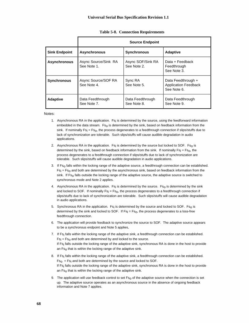
Universal Serial Bus Specification Revision 1.1
68
Table 5-8. Connection Requirements
Source Endpoint
Sink Endpoint Asynchronous Synchronous Adaptive
Asynchronous Async Source/Sink RASee Note 1.
Async SOF/Sink RASee Note 2.
Data + FeedbackFeedthroughSee Note 3.
Synchronous Async Source/SOF RASee Note 4.
Sync RASee Note 5.
Data Feedthrough +Application FeedbackSee Note 6.
Adaptive Data FeedthroughSee Note 7.
Data FeedthroughSee Note 8.
Data FeedthroughSee Note 9.
Notes:
1. Asynchronous RA in the application. Fsi is determined by the source, using the feedforward information
embedded in the data stream. Fso is determined by the sink, based on feedback information from the
sink. If nominally Fsi = Fso, the process degenerates to a feedthrough connection if slips/stuffs due to
lack of synchronization are tolerable. Such slips/stuffs will cause audible degradation in audioapplications.
2. Asynchronous RA in the application. Fsi is determined by the source but locked to SOF. Fso is
determined by the sink, based on feedback information from the sink. If nominally Fsi = Fso, the
process degenerates to a feedthrough connection if slips/stuffs due to lack of synchronization aretolerable. Such slips/stuffs will cause audible degradation in audio applications.
3. If Fso falls within the locking range of the adaptive source, a feedthrough connection can be established.
Fsi = Fso and both are determined by the asynchronous sink, based on feedback information from the
sink. If Fso falls outside the locking range of the adaptive source, the adaptive source is switched to
synchronous mode and Note 2 applies.
4. Asynchronous RA in the application. Fsi is determined by the source. Fso is determined by the sink
and locked to SOF. If nominally Fsi = Fso, the process degenerates to a feedthrough connection if
slips/stuffs due to lack of synchronization are tolerable. Such slips/stuffs will cause audible degradationin audio applications.
5. Synchronous RA in the application. Fsi is determined by the source and locked to SOF. Fso is
determined by the sink and locked to SOF. If Fsi = Fso, the process degenerates to a loss-free
feedthrough connection.
6. The application will provide feedback to synchronize the source to SOF. The adaptive source appears
to be a synchronous endpoint and Note 5 applies.
7. If Fsi falls within the locking range of the adaptive sink, a feedthrough connection can be established.
Fsi = Fso and both are determined by and locked to the source.
If Fsi falls outside the locking range of the adaptive sink, synchronous RA is done in the host to provide
an Fso that is within the locking range of the adaptive sink.
8. If Fsi falls within the locking range of the adaptive sink, a feedthrough connection can be established.
Fso = Fsi and both are determined by the source and locked to SOF.
If Fsi falls outside the locking range of the adaptive sink, synchronous RA is done in the host to provide
an Fso that is within the locking range of the adaptive sink.
9. The application will use feedback control to set Fso of the adaptive source when the connection is set
up. The adaptive source operates as an asynchronous source in the absence of ongoing feedbackinformation and Note 7 applies.

Universal Serial Bus Specification Revision 1.1
69
In cases where RA is needed but not available, the rate adaptation process could be mimicked by sampledropping/stuffing. The connection could then still be made, possibly with a warning about poor quality;otherwise, the connection cannot be made.
5.10.4.3.1 Audio ConnectivityWhen the above is applied to audio data streams, the RA process is replaced by sample rate conversion,which is a specialized form of rate adaptation. Instead of error control, some form of sample interpolationis used to match incoming and outgoing sample rates. Depending on the interpolation techniques used, theaudio quality (distortion, signal to noise ratio, etc.) of the conversion can vary significantly. In general,higher quality requires more processing power.
5.10.4.3.2 Synchronous Data ConnectivityFor the synchronous data case, RA is used. Occasional slips/stuffs may be acceptable to many applicationsthat implement some form of error control. Error control includes error detection and discard, errordetection and retransmit, or forward error correction. The rate of slips/stuffs will depend on the clockmismatch between the source and sink, and may be the dominant error source of the channel. If the errorcontrol is sufficient, then the connection can still be made.
5.10.5 Data PrebufferingThe USB requires that devices prebuffer data before processing/transmission to allow the host moreflexibility in managing when each pipe’s transaction is moved over the bus from frame to frame.
For transfers from function to host, the endpoint must accumulate samples during frame X until it receivesthe SOF token for frame X+1. It “latches” the data from frame X into its packet buffer and is now ready tosend the packet containing those samples during frame X+1. When it will send that data during the frameis determined solely by the Host Controller and can vary from frame to frame.
For transfers from host to function, the endpoint will accept a packet from the host sometime during frameY. When it receives the SOF for frame Y+1, it can then start processing the data received in frame Y.
This approach allows an endpoint to use the SOF token as a stable clock with very little jitter and/or driftwhen the Host Controller moves the packet over the bus. This approach also allows the Host Controller tovary within a frame precisely when the packet is actually moved over the bus. This prebufferingintroduces some additional delay between when a sample is available at an endpoint and when it movesover the bus compared to an environment where the bus access is at exactly the same time offset from SOFfrom frame to frame.
Figure 5-16 shows the time sequence for a function-to-host transfer (IN process). Data D0 is accumulatedduring frame Fi at time Ti, and transmitted to the host during frame Fi+1. Similarly, for a host-to-functiontransfer (OUT process), data D0 is received by the endpoint during frame Fi+1 and processed during frameFi+2.

Universal Serial Bus Specification Revision 1.1
70
Time:
Frame:
Data on Bus:
OUT Process:
IN Process
T i T i+1 T i+2 T i+3 ... T m T m+1 ...
F i F i+1 F i+2 F i+3 ... F m F m+1 ...
D 0 D 1 D 2 ... D 0 D 1 ...
D 0 D 1 ... D 0 ...
D 0 D 1 ... D 0 ...
Figure 5-16. Data Prebuffering
5.10.6 SOF TrackingFunctions supporting isochronous pipes must receive and comprehend the SOF token to supportprebuffering as previously described. Given that SOFs can be corrupted, a device must be prepared torecover from a corrupted SOF. These requirements limit isochronous transfers to full-speed devices only,because low-speed devices do not see SOFs on the bus. Also, because SOF packets can be damaged intransmission, devices that support isochronous transfers need to be able to synthesize the existence of anSOF that they may not see due to a bus error.
Isochronous transfers require the appropriate data to be transmitted in the corresponding frame. The USBrequires that when an isochronous transfer is presented to the Host Controller, it identifies the framenumber for the first frame. The Host Controller must not transmit the first transaction before the indicatedframe number. Each subsequent transaction in the IRP must be transmitted in succeeding frames. If thereare no transactions pending for the current frame, then the Host Controller must not transmit anything foran isochronous pipe. If the indicated frame number has passed, the Host Controller must skip (i.e., nottransmit) all transactions until the one corresponding to the current frame is reached.
5.10.7 Error HandlingIsochronous transfers provide no data packet retries (i.e., no handshakes are returned to a transmitter by areceiver) so that timeliness of data delivery is not perturbed. However, it is still important for the agentsresponsible for data transport to know when an error occurs and how the error affects the communicationflow. In particular, for a sequence of data packets (A, B, C, D), the USB allows sufficient information suchthat a missing packet (A, _, C, D) can be detected and will not unknowingly be turned into an incorrectdata or time sequence (A, C, D or A, _, B, C, D). The protocol provides four mechanisms that support this:exactly one packet per frame, SOF, CRC, and bus transaction timeout.
� Isochronous transfers require exactly one data transaction every frame for normal operation. The USBdoes not dictate what data is transmitted in each frame. The data transmitter/source determinesspecifically what data to provide. This regular data-per-frame provides a framework that isfundamental to detecting missing data errors. Any phase of a transaction can be damaged duringtransmission on the bus. Chapter 8 describes how each error case affects the protocol.
� Because every frame is preceded by an SOF and a receiver can see SOFs on the bus, a receiver candetermine that its expected transaction did not occur between two SOFs. Additionally, because evenan SOF can be damaged, a device must be able to reconstruct the existence of a missed SOF asdescribed in Section 5.10.6.

Universal Serial Bus Specification Revision 1.1
71
� A data packet may be corrupted on the bus; therefore, CRC protection allows a receiver to determinethat the data packet it received was corrupted.
� The protocol defines the details that allow a receiver to determine via bus transaction timeout that it isnot going to receive its data packet after it has successfully seen its token packet.
Once a receiver has determined that a data packet was not received, it may need to know the size of thedata that was missed in order to recover from the error with regard to its functional behavior. If thecommunication flow is always the same data size per frame, then the size is always a known constant.However, in some cases the data size can vary from frame to frame. In this case, the receiver andtransmitter have an implementation-dependent mechanism to determine the size of the lost packet.
In summary, whether a transaction is actually moved successfully over the bus or not, the transmitter andreceiver always advance their data/buffer streams one transaction per frame to keep data-per-timesynchronization. The detailed mechanisms described above allow detection, tracking, and reporting ofdamaged transactions so that a function or its client software can react to the damage in a function-appropriate fashion. The details of that function- or application-specific reaction are outside the scope ofthe USB Specification.
5.10.8 Buffering for Rate MatchingGiven that there are multiple clocks that affect isochronous communication flows in the USB, buffering isrequired to rate match the communication flow across the USB. There must be buffer space available bothin the device per endpoint and on the host side on behalf of the client software. These buffers providespace for data to accumulate until it is time for a transfer to move over the USB. Given the natural datarates of the device, the maximum size of the data packets that move over the bus can also be calculated.Figure 5-17 shows the equations used to determine buffer size on the device and host and maximum packetsize that must be requested to support a desired data rate. These equations allow a device and clientsoftware design time-determined service clock rate (variable X), sample clock rate (variable C), and samplesize (variable S). The USB allows only one transaction per bus clock. These equations should providedesign information for selecting the appropriate packet size that an endpoint will report in its characteristicinformation and the appropriate buffer requirements for the device/endpoint and its client software. Figure5-14 shows actual buffer, packet, and clock values for a typical isochronous example.

Universal Serial Bus Specification Revision 1.1
72
X Service Clock
1KHz Bus Clock
C Sample Clock(S byte/sample)
M = (2 * N * P) Byte Bufferfor 2 Services,
N = (CEIL(1KHz / X)) packetsper service
B = 2 * PByte Buffer(2 Packets)
P = (CEIL(C / 1KHz) * S)Byte Packets
Isochronous Rate (Clock) MatchingBy Buffering
Figure 5-17. Packet and Buffer Size Formulas for Rate-Matched Isochronous Transfers
The USB data model assumes that devices have some natural sample size and rate. The USB supports thetransmission of packets that are multiples of sample size to make error recovery handling easier whenisochronous transactions are damaged on the bus. If a device has no natural sample size or if its samplesare larger than a packet, it should describe its sample size as being one byte. If a sample is split across adata packet, the error recovery can be harder when an arbitrary transaction is lost. In some cases, datasynchronization can be lost unless the receiver knows in what frame number each partial sample istransmitted. Furthermore, if the number of samples can vary due to clock correction (e.g., for anon-derived device clock), it may be difficult or inefficient to know when a partial sample is transmitted.Therefore, the USB does not split samples across packets.

Universal Serial Bus Specification Revision 1.1
73
Chapter 6
Mechanical
This chapter provides the mechanical and electrical specifications for the cables, connectors, and cableassemblies used to interconnect USB devices. The specification includes the dimensions, materials,electrical, and reliability requirements. This chapter documents minimum requirements for the externalUSB interconnect. Substitute material may be used as long as it meets these minimums.
6.1 Architectural OverviewThe USB physical topology consists of connecting the downstream hub port to the upstream port of anotherhub or to a device. The USB can operate at two speeds. Full-speed, 12 Mb/s, requires the use of a shieldedcable with two power conductors and twisted pair signal conductors. Low-speed, 1.5 Mb/s, relaxes thecable requirement. Low-speed cable does not require shielding or twisted pair signal conductors.
The connectors are designed to be hot plugged. The USB Icon on the plugs provides tactile feedbackmaking it easy to obtain proper orientation.
6.2 Keyed Connector ProtocolTo minimize end user termination problems, USB uses a “keyed connector” protocol. The physicaldifference in the Series “A” and “B” connectors insure proper end user connectivity. The “A” connector isthe principle means of connecting USB devices. All USB devices must have an “A” connector. The “B”connector allows device vendors to provide a standard detachable cable. This facilitates end user cablereplacement. Figure 6-1 illustrates the keyed connector protocol.
Series "A" Connectors Series "B" Connectors
� Series "A" plugs arealways oriented upstreamtowards the Host System
� Series "B" plugs arealways orienteddownstream towards theUSB Device
"A" Plugs(From the
USB Device) "B" Plugs(From the
Host System)
"B" Receptacles(Upstream Input to theUSB Device or Hub)
"A" Receptacles(Downstream Outputfrom the USB Host or
Hub)
Figure 6-1. Keyed Connector Protocol
The following list explains how the plugs and receptacles can be mated:

Universal Serial Bus Specification Revision 1.1
74
� Series “A” receptacle mates with a Series “A” plug. Electrically, Series “A” receptacles function asoutputs from host systems and/or hubs.
� Series “A” plug mates with a Series “A” receptacle. The Series “A” plug always is oriented towardsthe host system.
� Series “B” receptacle mates with a Series “B” plug (male). Electrically, Series “B” receptaclesfunction as inputs to hubs or devices.
� Series “B” plug mates with a Series “B” receptacle. The Series “B” plug is always oriented towardsthe USB hub or device.
6.3 CableUSB cable consists of four conductors, two power conductors and two signal conductors.
Full-speed cable consists of a signaling twisted pair, VBUS, GND, and an overall shield. Full-speed cablemust be marked to indicate suitability for USB usage (see Section 6.6.2). Full-speed cable may be usedwith either Low-speed or Full-speed devices. When Full-speed cable is used with Low-speed devices, thecable must meet all Low-speed requirements.
Low-speed cable does not require twisted signaling conductors or the overall shield.
6.4 Cable AssemblyThis specification describes three USB cable assemblies. Detachable cable, Full-speed captive cable, andLow-speed captive cable.
The color used for the cable assembly is vendor specific, recommended colors are White, Grey, or Black.
6.4.1 Detachable Cable AssembliesFull-speed devices can utilize the “B” connector. This allows the device to have a detachable USB cable.This eliminates the need to build the device with a hardwired cable and minimizes end user problems ifcable replacement is necessary.
Devices utilizing the “B” connector must be designed to work with worst case maximum length detachablecable. Detachable cable assemblies may be used only on Full-speed devices. Using a Full-speed detachablecable on a Low-speed device may exceed the maximum Low-speed cable length.
Figure 6-2 illustrates a detachable cable assembly.

Universal Serial Bus Specification Revision 1.1
75
C
Series "A" Plug to Series "B" Plug
USB DetachableCable Assembly
SIZE DRAWING NUMBER REV
A N/ADATE
2/98
SCALE: N/A SHEET 1 of 1
H
G
F
E
D
C
B
A
8 7 6 5 4 3 2 1
H
G
F
E
D
C
B
A
8 7 6 5 4 3 2 1
Detail B - B(Series "B" Plug)
Detail A - A(Series "A" Plug)
2 1
3 4
12.0
32.0
9.0
10.511.5
3 41 2
27.0
12.0
9.0
7.515.7
Opt ional MoldedStrain Relief
Al l d imensions are in mi l l imeters ( m m )unless otherwise noted.
Dimensions are TYPICAL and are forgeneral reference purposes only.
Aluminum Metal l ized Polyester Inner Shield
Black (Ground)
28 AWG STC Dra in Wi re
> 65% Tinned Copper Bra ided Shie ld
Polyvinyl Chlor ide (PVC) Jacket
Green (D +)
White (D -)
Red (VBUS)
Detail C - C(Typical USB Shielded Cable)
IMPORTANT NOTICE: All detachable cable assemblies must be Full Speed .
CC
CC
A
A
B
B
Overmolded Series "B" Plug(Always downstream towards the USB Device.)
Overmolded Series "A" Plug(Always upstream towards the "host" system.)
Figure 6-2. USB Detachable Cable Assembly
Universal Serial Bus Specification Revision 1.1
76
Detachable Cables must meet the following electrical requirements:
� The cable must be terminated on one end with an overmolded Series “A” plug and the opposite end isterminated with an overmolded Series “B” plug.
� The cable must be rated for Full-speed.
� The cable impedance must match the impedance of the Full-speed drivers. The drivers arecharacterized to drive specific cable impedance. Refer to Section 7.1.1 for details.
� The maximum allowable cable length is determined by signal pair attenuation. Refer to Section 7.1.17for details.
� The maximum allowable cable length determined by the cable propagation delay. The USB utilizes anunterminated transmission scheme. Exceeding this limit will cause signaling reflections to interferewith data transmission. Refer to Section 7.1.14 for details.
� Differences in propagation delay between the two signal conductors must be minimized. Refer toChapter 7.1.3 for details.
� The GND lead provides a common ground reference between the upstream and downstream ports. Themaximum cable length is limited by the voltage drop across the GND lead. Refer to Section 7.2.2 fordetails. The minimum acceptable wire gauge is calculated assuming the attached device is high power
� The VBUS lead provides power to the connected device. For detachable cables, the VBUS requirementis the same as the GND lead.
6.4.2 Full-speed Captive Cable AssembliesFull-speed captive cable assemblies may be used with either Full-speed or Low-speed devices. Assembliesare considered captive if they are provided with a vendor-specific disconnect means. When using a Full-speed captive cable on a Low-speed device the cable must meet all Low-speed requirements.
Figure 6-3 illustrates a Full-speed cable assembly.

Universal Serial Bus Specification Revision 1.1
77
C
Series "A" Plug to Cut End
USB Full SpeedHardwired Cable AssemblySIZE DRAWING NUMBER REV
A N/ADATE
2/98
SCALE: N/A SHEET 1 of 1
H
G
F
E
D
C
B
A
8 7 6 5 4 3 2 1
H
G
F
E
D
C
B
A
8 7 6 5 4 3 2 1
Cut End(A lways downstream towards the USB Device.)
Overmolded Series "A" Plug(A lways upst ream towards the "host" system.)
A l l d imens ions a re i n m i l l ime te rs (m m )unless otherwise note.
D i m e n s i o n s a r e T Y P I C A L a n d a r e f o rgeneral reference purposes only.
A
A
B
B
Blunt Cut Terminat ion(Length Dimension Point)
Polyvinyl Chlor ide (PVC)Jacket
Blunt Cut Termination Prepared Termination
Metal l ized Mylar Inner Shield
> 65% Tinned Copper Bra idedShield
Polyvinyl Chlor ide (PVC) Jacket
Red (VBUS)Black (Ground)Green (D +)White (D -)
28 AWG STC Dra in Wi re
User Speci f ied
Length Dimension Point
Detail B - B (Typical Terminations)
Detail A - A(Series "A" Plug)
1 2 3 4
27.0
12.0
9.0
7.515.7
Opt ional MoldedStrain Relief
Figure 6-3. USB Full-speed Hardwired Cable Assembly

Universal Serial Bus Specification Revision 1.1
78
Full-speed Captive Cables must meet the following electrical requirements:
� The cable must be terminated on one end with an overmolded Series “A” plug and the opposite end isvendor specific. If the vendor specific interconnect is to be hot plugged it must meet the sameperformance requirements as the USB “B” connector.
� The cable must be rated for Full-speed.
� The cable impedance must match the impedance of the Full-speed drivers. The drivers arecharacterized to drive specific cable impedance. Refer to Section 7.1.1 for details.
� The maximum cable length is determined by the attenuation of the signal pair. Refer to Section 7.1.17for details.
� The maximum cable length is determined by the propagation delay though the cable. The USB utilizesan unterminated transmission scheme, exceeding this limit will cause signaling reflections to interferewith data transmission. Refer to Section 7.1.14 for details.
� Differences in propagation delay between the two signal conductors must be minimized. Refer toSection 7.1.3 for details.
� The GND lead provides a common reference between the upstream and downstream ports. Themaximum cable length is determined by the voltage drop across the GND lead. Refer to Section 7.2.2for details. The minimum wire gauge is calculated using the worst case current consumption.
� The VBUS lead provides power to the connected device. The minimum wire gauge is vendor specific.
6.4.3 Low-speed Captive Cable AssembliesAssemblies are considered captive if they are provided with a vendor-specific disconnect means. Low-speed cable may only be used on Low-speed devices.
Figure 6-4 illustrates a Low-speed cable assembly.

Universal Serial Bus Specification Revision 1.1
79
C
Series "A" Plug to Cut End
USB Low SpeedHardwired Cable AssemblySIZE DRAWING NUMBER REV
A N/ADATE
2/98
SCALE: N/A SHEET 1 of 1
H
G
F
E
D
C
B
A
8 7 6 5 4 3 2 1
H
G
F
E
D
C
B
A
8 7 6 5 4 3 2 1
Detail A - A(Series "A" Plug)
1 2 3 4
27.0
12.0
9.0
7.515.7
Opt ional MoldedStrain Relief
A l l d imens ions a re i n m i l l ime te rs (m m )unless otherwise noted.
D i m e n s i o n s a r e T Y P I C A L a n d a r e f o rgeneral reference purposes only.
A
A
B
B
Cut End(Always downstream towards the USB Device.)
Overmolded Series "A" Plug(Always upstream towards the "host" system.)
IMPORTANT NOTICE: For use in Low Speed applications only.
Detail B - B (Typical Terminations)
Blunt Cut Terminat ion(Length Dimension Point)
Polyvinyl Chlor ide (PVC)Jacket
Blunt Cut Termination Prepared Termination
Black (Ground)
User Speci f ied
Length Dimension Point
Red (VBUS)
White (D -)
Green (D +)
Polyvinyl Chlor ide (PVC) Jacket
Figure 6-4. USB Low-speed Hardwired Cable Assembly

Universal Serial Bus Specification Revision 1.1
80
Low-speed Captive Cables must meet the following electrical requirements:
� The cable must be terminated on one end with an overmolded Series “A” plug and the opposite end isvendor specific. If the vendor specific interconnect is to be hot plugged it must meet the sameperformance requirements as the USB “B” connector.
� Low-Speed drivers are characterized for operation over a range of capacitive loads. This value includesall sources of capacitance on the D+ and D-lines, not just the cable. Cable selection must insure thattotal load capacitance falls between specified minimum and maximum values. If the desiredimplementation does not meet the minimum requirement, additional capacitance needs to be added tothe device. Refer to section 7.1.1.2 for details.
� The maximum Low-speed cable length determined by the rise and fall times of Low-speed signaling.This forces Low-speed cable to be significantly shorter then Full-speed. Refer to Section 7.1.1.2 fordetails.
� Differences in propagation delay between the two signal conductors must be minimized. Refer toSection 7.1.3 for details.
� The GND lead provides a common reference between the upstream and downstream ports. Themaximum cable length is determined by the voltage drop across the GND lead. Refer to Section 7.2.2for details. The minimum wire gauge is calculated using the worst case current consumption.
� The VBUS lead provides power to the connected device. The minimum wire gauge is vendor specific.
6.4.4 Prohibited Cable AssembliesUSB is optimized for ease of use. The expectation it that if the device can be plugged in it will work.By specification, the only conditions that prevent a USB device from being successfully utilized arelack of power, lack of bandwidth, and excessive topology depth. These conditions are well understoodby the system software.
Non-acceptable cables may work in some situations but they cannot be guaranteed to work in allinstances.
� Extension cableCables that provide a Series “A” plug with a series “A” receptacle or a Series “B” plug with aSeries “B” receptacle. This allows multiple cable segments to be connected together, possiblyexceeding the maximum permissible cable length.
� Cable assembly that violates USB topology rulesA cable with both ends terminated in either Series “A” plugs or Series “B” receptacles. This cableallows two downstream ports to be directly connected.
Note: This prohibition does not prevent using a USB device to provide a bridge between two USBbusses.
� Low-speed detachable cableDetachable cables must be Full-speed. Low-speed devices are prohibited from using detachablecables. Detachable cable is Full-speed rated, using a long Full-speed cable exceeds the capacitiveload of Low-speed.
6.5 Connector Mechanica l Configuration and Material RequirementsThe USB Icon is used to identify USB plugs and the receptacles. Figure 6-5 illustrates the USB Icon

Universal Serial Bus Specification Revision 1.1
81
L0.5 L
L
L
L
0.33 L
0.33 L
0.33 LL
1.50 L
1.50 L
1.67 L
2.33 L
3.75 L5.00 L
5.17 L
6.25 L
8.00 L
Dia:1.67 L
L
Dia:1.33 L
Dia:L
Dia:L
Dia:LDia:L
Dia:1.33 L
All dimensions are ± 5%
Figure 6-5. USB Icon
6.5.1 USB Icon LocationThe USB Icon is embossed, in a recessed area, on the topside of the USB plug. This provides easy userrecognition and facilitates alignment during the mating process. The USB Icon and Manufacture’s logoshould not project beyond the overmold surface. The USB Icon is required, while the Manufacture’s logo isrecommended, for both Series “A” and “B” plug assemblies. The USB Icon is also located adjacent to eachreceptacle. Receptacles should be oriented to allow the Icon on the plug to be visible during the matingprocess. Figure 6-6 illustrates the typical plug orientation.
Manufacturer'sEngraved Logo
A
A
Top View
Optional Top"Locator Detail"
Optional Top"Locator Detail"
LocatorHeight
Approximately0.6mm
(0.024")
Locator WidthApproximately
0.5mm(0.020")
4
3
2
1
Engraved USBIcon
Section A - A(Plug Cross-Section)
Overmolding
0.6mm (0.024") MaxManufacturer's
LogoEngraving Recess
0.6mm (0.024")Max
USB IconEngraving Recess
Figure 6-6. Typical USB Plug Orientation

Universal Serial Bus Specification Revision 1.1
82
6.5.2 USB Connector Termination DataTable 6-1 provides the standardized contact terminating assignments by number and electrical value forSeries “A” and Series “B” connectors.
Table 6-1. USB Connector Termination Assignment
Contact
NumberSignal Name
Typical Wiring
Assignment
1 VBUS Red
2 D- White
3 D+ Green
4 GND Black
Shell Shield Drain Wire
6.5.3 Series “A” and Series “B” ReceptaclesElectrical and mechanical interface configuration data for Series "A" and Series "B" receptacles are shownin Figure 6-7 and Figure 6-8. Also, refer to Figure 6-12, Figure 6-13, and Figure 6-14 at the end of thischapter for typical PCB receptacle layouts.

Universal Serial Bus Specification Revision 1.1
83
Ove
rmol
d B
oot
2 .67 MIN
Ful ly Mated Series "A"Receptacle and Plug
Receptacle F lange
1
USB Series "A" Receptacle and PlugMating Features
1Al low a min imum spacing of 2.67mm betweenthe face of the receptacle and the plugovermold boot .
8 .0 MAX
SCALE: N/A
Interface and Mating Drawing
Series "A" ReceptacleSIZE DRAWING NUMBER REV
A N/ADATE
2/98 CSHEET 1 of 1
H
G
F
E
D
C
B
A
8 7 6 5 4 3 2 1
H
G
F
E
D
C
B
A
8 7 6 5 4 3 2 1
0.38 ± 0.13
8.38 ± 0.08
8.88 ± 0.20
4.98 ± 0.25Contact Point
300 ± 2 0 (2)
0.50 ± 0.10
4.13 REF
Center Line of 5.12
Receptacle Contact
Printed Circui t Board
300 ± 2 0 (2)
0.50 ± 0.10 (2)
B Center Line
C
1 2 3 4
1.84 ± 0.05
12.50 ± 0.10
11.10 ± 0.10
R 0.64 ± 0.13 (Typical)
0.64 ± 0.13 (8)
5.12 ± 0.10
1.00 ± 0.05 (4)
R 0.32 ± 0.13 (Typical)
B
C Center Line
3.50 ± 0.05 (2)
1.00 ± 0.05 (2)
A
USB Series "A" Receptacle Interface
All dimensions are in mil l imeters (mm ) unlessotherwise noted.
Figure 6-7. USB Series "A" Receptacle Interface and Mating Drawing

Universal Serial Bus Specification Revision 1.1
84
SCALE: N/A
Interface and Mating Drawing
USB Series "B" ReceptacleSIZE D R A W I N G N U M B E R R E V
A N/ADATE
2/98 CS H E E T 1 of 1
H
G
F
E
D
C
B
A
8 7 6 5 4 3 2 1
H
G
F
E
D
C
B
A
8 7 6 5 4 3 2 1
C Center Line
300 + 20 (4)
8.38 + 0.08
0.38 + 0.13 (4)
8.45 + 0.10
5.60 + 0.10
1.00 + 0.05 (4) 1.25 + 0.10 (4)
12
43
A
8.88 + 0.20
3.18 + 0.05
B
C
7.78 + 0.10
450 + 0.50 (2)
R 0.38 (6)
3.67 + 0.08 0.80 + 0.08
1.63 + 0.05 (2)
B Center Line
Contact Point4.98 + 0.25
Receptacle Contact
B Center Line
300 + 20 (2)
Receptacle Housing
0.50 + 0.10 (2)
3.67 Center Line
Receptacle Shel l
Receptacle Shel l
Ful ly Mated Plug and Receptacle
2.67 MIN
Ove
rmol
d B
oot
Ove
rmol
d B
oot
USB Series "B" Receptacle and Plug Mating Features
10.5 MAX 11.5 MAX
USB Series "B" Receptacle Interface
1
1Al low a minimum spacing of 2.67mm between theface of the receptacle and the plug overmold boot.
All dimensions are in mil l imeters (m m )unless otherwise noted.
Figure 6-8. USB Series "B" Recptacle Interface and Mating Drawing

Universal Serial Bus Specification Revision 1.1
85
6.5.3.1 Receptacle Injection Molded Thermoplastic Insulator MaterialMinimum UL 94-V0 rated, thirty percent (30%) glass-filled polybutylene terephthalate (PBT) orpolyethylene terephthalate (PET) or better.
Typical Colors: Black, Gray and Natural.
Flammability Characteristics: UL 94-V0 rated.
Flame Retardant Package must meet or exceed the requirements for UL, CSA, VDE, et cetera.
Oxygen Index (LOI): Greater than 21%. ASTM D 2863.
6.5.3.2 Receptacle Shell Mate rialsSubstrate Material: 0.30 + 0.05 mm phosphor bronze, nickel silver or other copper based high strengthmaterials.
Plating:
1. Underplate: Optional. Minimum 1.00 micrometers (40 microinches) Nickel. In addition,manufacturer may use a copper underplate beneath the nickel.
2. Outside: Minimum 2.5 micrometers (100 microinches) Bright Tin or Bright Tin-Lead.
6.5.3.3 Receptacle Contact MaterialsSubstrate Material: 0.30 + 0.05 mm minimum half-hard phosphor bronze or other the high strength copperbased material.
Plating: Contacts are to be selectively plated.
A. Option I
1. Underplate: Minimum 1.25 micrometers (50 microinches) Nickel. Copper over base materialis optional.
2. Mating Area: Minimum 0.05 micrometers (2 microinches) Gold over a minimum of 0.70micrometers (28 microinches) Palladium.
3. Solder Tails: Minimum 3.8 micrometers (150 microinches) Bright Tin-Lead over theunderplate.
B. Option II
1. Underplate: Minimum 1.25 micrometers (50 microinches) Nickel. Copper over base materialis optional.
2. Mating Area: Minimum 0.05 micrometers (2 microinches) Gold over a minimum of 0.75micrometers (30 microinches) Palladium-Nickel.
3. Solder Tails: Minimum 3.8 micrometers (150 microinches) Bright Tin-Lead over theunderplate.
C. Option III
1. Underplate: Minimum 1.25 micrometers (50 microinches) Nickel. Copper over base materialis optional.
2. Mating Area: Minimum 0.75 micrometers (30 microinches) Gold.
3. Solder Tails: Minimum 3.8 micrometers (150 microinches) Bright Tin-Lead over theunderplate.

Universal Serial Bus Specification Revision 1.1
86
6.5.4 Series “A” and Series “B” PlugsElectrical and mechanical interface configuration data for Series "A" and Series "B" plugs are shown inFigure 6-9 and Figure 6-10.

Universal Serial Bus Specification Revision 1.1
87
SCALE: N/A
Interface Drawing
USB Series "A" PlugSIZE DRAWING NUMBER REV
A N/ADATE
2/98 CSHEET 1 of 1
H
G
F
E
D
C
B
A
8 7 6 5 4 3 2 1
H
G
F
E
D
C
B
A
8 7 6 5 4 3 2 1
2.00 ± 0.05 (2)
A
1.00 ± 0.05 (4)
4 3 2 1
B
B
11.75 MIN
300 ± 20
4.50 ± 0.10
0.15 ± 0.10 Typical 300 ± 20 Typical
1.95 ± 0.05
12.00 ± 0.10
0.315 ± 0.03 Typical
8 .0 MAX
16.0 MAX
8.0 MAX
4.0 MAX
AA
0.38 ± 0.13
2.50 ± 0.05 (2)
2.50 ± 0.13 (4)
Plug Contact
B
1 11.75 MIN
2.00 ± 0.13 (4)5.16 ± 0.10B Center Line
B Center Line
UL 94-V0 Plug Housing
R 0.64 + 0.13 Typical
Ove
rmol
d B
oot
1Overal l connector and cable assemblylength is measured f rom Datum 'A ' o fthe Series "A" Plug to Datum 'A' of theS e r i e s " B " P l u g o r t o t h e b l u n t e n dterminat ion.
8.65 ± 0.197.41 ± 0.31
4.2 MINGOLD PLATE AREA
3.5 ± 0.05 (2)
1.0 ± 0.05 (2)
6.41 ± 0.31
9.70 ± 0.13
Section A - A
Overmold Boot
0.13 ± 0.13
0.16 ± 0.15
Section B - B
All dimensions are in mil l imeters (m m )unless otherwise noted.
Figure 6-9. USB Series "A" Plug Interface Drawing
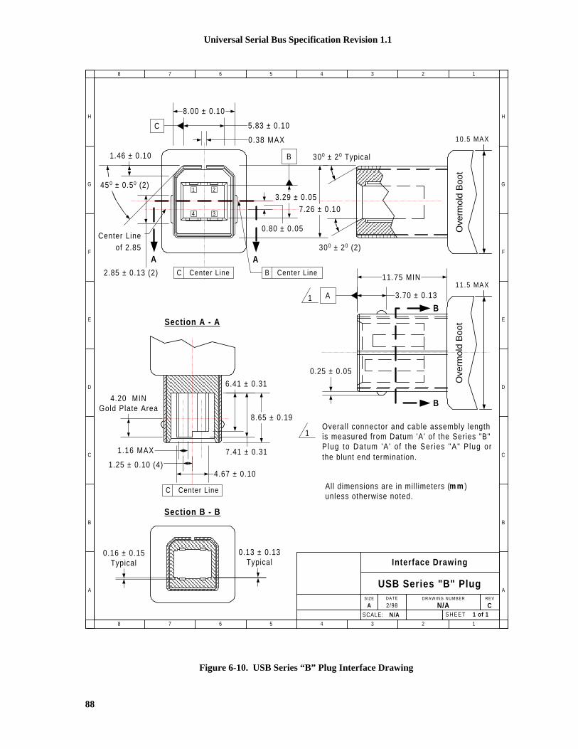
Universal Serial Bus Specification Revision 1.1
88
Section B - B
0.80 ± 0.05
A A
1.46 ± 0.10
SCALE: N/A
Interface Drawing
USB Series "B" PlugSIZE DRAWING NUMBER REV
A N/ADATE
2/98 CSHEET 1 of 1
H
G
F
E
D
C
B
A
8 7 6 5 4 3 2 1
H
G
F
E
D
C
B
A
8 7 6 5 4 3 2 1
8.00 ± 0.10
5.83 ± 0.10
0.38 MAX
C
450 ± 0.50 (2)
2.85 ± 0.13 (2)
7.26 ± 0.10
Center Lineof 2.85
3.29 ± 0.05
B 300 ± 2 0 Typical
300 ± 2 0 (2)
B Center LineC Center Line
1 2
34
3.70 ± 0.13
11.75 MIN
A1
B
B
1Overal l connector and cable assembly lengthis measured from Datum 'A' of the Series "B"P lug to Datum 'A ' o f the Ser ies "A" P lug orthe blunt end termination.
C Center Line
Section A - A
4.67 ± 0.10
8.65 ± 0.19
7.41 ± 0.31
6.41 ± 0.31
1.25 ± 0.10 (4)
4.20 MINGold Plate Area
1.16 MAX
0.13 ± 0.13Typical
0.16 ± 0.15Typical
10.5 MAX
Ove
rmol
d B
oot
Ove
rmol
d B
oot
11 .5 MAX
All dimensions are in mil l imeters (m m )unless otherwise noted.
0.25 ± 0.05
Figure 6-10. USB Series “B” Plug Interface Drawing

Universal Serial Bus Specification Revision 1.1
89
6.5.4.1 Plug Injection Molded Thermoplastic Insulator MaterialMinimum UL 94-V0 rated, thirty percent (30%) glass-filled polybutylene terephthalate (PBT) orpolyethylene terephthalate (PET) or better.
Typical Colors: Black, Gray and Natural.
Flammability Characteristics: UL 94-V0 rated.
Flame Retardant Package must meet or exceed the requirements for UL, CSA and VDE.
Oxygen Index (LOI): 21%. ASTM D 2863.
6.5.4.2 Plug Shell MaterialsSubstrate Material: 0.30 + 0.05 mm phosphor bronze, nickel silver or other suitable material.
Plating:
A. Underplate: Optional. Minimum 1.00 micrometers (40 microinches) nickel. In addition,manufacturer may use a copper underplate beneath the nickel.
B. Outside: Minimum 2.5 micrometers (100 microinches) bright tin or bright tin-lead.
6.5.4.3 Plug (Male) Contact MaterialsSubstrate Material. 0.30 + 0.05 mm half-hard phosphor bronze.
Plating. Contacts are to be selectively plated.
A. Option I
1. Underplate: Minimum 1.25 micrometers (50 microinches) nickel. Copper over base materialis optional.
2. Mating Area: Minimum 0.05 micrometers (2 microinches) gold over a minimum of 0.70micrometers (28 microinches) palladium.
3. Solder Tails: Minimum 3.8 micrometers (150 microinches) bright tin-lead over theunderplate.
B. Option II
1. Underplate: Minimum 1.25 micrometers (50 microinches) nickel. Copper over base materialis optional.
2. Mating Area: Minimum 0.05 micrometers (2 microinches) gold over a minimum of 0.75micrometers (30 microinches) palladium-nickel.
3. Wire Crimp/Solder Tails: Minimum 3.8 micrometers (150 microinches) bright tin-lead overthe underplate.
C. Option III
1. Underplate: Minimum 1.25 micrometers (50 microinches) nickel. Copper over base materialis optional.
2. Mating Area: Minimum 0.75 micrometers (30 microinches) gold.
3. Solder Tails: Minimum 3.8 micrometers (150 microinches) bright tin-lead over theunderplate.

Universal Serial Bus Specification Revision 1.1
90
6.6 Cable Mechanical Con figuration and Material RequirementsFull-speed and Low-speed cables differ in data conductor arrangement and shielding. Low-speed cabledoes not require twisted data conductors or a shield. Figure 6-11 shows the typical Full-speed cableconstruction.
BR
G
W
Polyvinyl Chloride (PVC) Jacket
Outer Shield > 65% InterwovenTinned Copper Braid
Inner Shield AluminumMetallized Polyester
28 AWG TinnedCopper Drain Wire
Twisted Signaling Pair:White: D-Green: D+
Non-Twisted Power Pair:Red: V BUS
Black: Power Ground
Figure 6-11. Typical Full-speed Cable Construction
6.6.1 DescriptionFull-speed cable consists of one 28 to 20 AWG non-twisted power pair and one 28 AWG twisted data pairwith an aluminum metallized polyester inner shield, 28 AWG stranded tinned copper drain wire, > 65%tinned copper wire interwoven (braided) outer shield and PVC outer jacket.
Low-speed cable does not require the data pair be twisted or a shield and drain wire.

Universal Serial Bus Specification Revision 1.1
91
6.6.2 ConstructionRaw materials used in the fabrication of this cable shall be of such quality that the fabricated cable iscapable of meeting or exceeding the mechanical and electrical performance criteria of the most currentUSB Specification Revision, and all applicable domestic and international safety/testing agencyrequirements, e.g., UL, CSA, BSA, NEC, et cetera, for electronic signaling and power distribution cables inits category.
Table 6-2. Power Pair
American WireGauge (AWG)
Nominal ConductorOuter Diameter
Stranded TinnedConductors
280.381 mm (0.015”)
0.406 mm (0.016”)
7 x 36
19 x 40
260.483 mm (0.019”)
0.508 mm (0.020”)
7 x 34
19 x 38
240.610 mm (0.024”)
0.610 mm (0.024”)
7 x 32
19 x 36
220.762 mm (0.030”)
0.787 mm (0.031”)
7 x 30
19 x 34
200.890 mm (0.035”)
0.931 mm (0.037”)
7 x 28
19 x 32
Note: Minimum conductor construction shall be stranded tinned copper.
Non-Twisted Power Pair:
A. Wire Gauge: Minimum 28 AWG or as specified by the user contingent upon the specified cablelength. Refer to Table 6-2.
B. Wire Insulation: Semirigid polyvinyl chloride (PVC).
1. Nominal Insulation Wall Thickness: 0.25 mm (0.010”).
2. Typical Power (VBUS) Conductor: Red Insulation.
3. Typical Ground Conductor: Black Insulation.
Signal Pair:
A. Wire Gauge: 28 AWG minimum. Refer to Table 6-3.
Table 6-3. Signal Pair
American WireGauge (AWG)
Nominal ConductorOuter Diameter
Stranded TinnedConductors
280.381 mm (0.015”)
0.406 mm (0.016”)
7 x 36
19 x 40

Universal Serial Bus Specification Revision 1.1
92
Note: Minimum conductor construction shall be stranded tinned copper
B. Wire Insulation: High-density polyethylene (HDPE), alternately foamed polyethylene or foamedpolypropylene.
1. Nominal Insulation Wall Thickness: 0.31 mm (0.012”).
2. Typical Data Plus (+) Conductor: Green Insulation.
3. Typical Data Minus (-) Conductor: White Insulation.
C. Nominal Twist Ratio (not required for Low-speed): One full twist every 60 mm (2.36”) to 80 mm(3.15”).
Aluminum Metallized Polyester Inner Shield (not required for Low-speed):
A. Substrate Material: Polyethylene terephthalate (PET) or equivalent material.
B. Metallizing: Vacuum deposited aluminum.
C. Assembly:
1. The aluminum metallized side of the inner shield shall be positioned facing out to ensuredirect contact with the drain wire.
2. The aluminum metallized inner shield shall over lap by approximately one-quarter turn.
Drain Wire (not required for Low-speed):
A. Wire Gauge: Minimum 28 AWG stranded tinned copper (STC) non-insulated. Refer to Table6-4.
Table 6-4. Drain Wire Signal Pair
American WireGauge (AWG)
Nominal ConductorOuter Diameter
Stranded Tinned
Conductors
280.381 mm (0.015”)
0.406 mm (0.016”)
7 x 36
19 x 40
Interwoven (Braided) Tinned Copper Wire (ITCW) Outer Shield (not required for Low-speed):
A. Coverage Area: Minimum 65%.
B. Assembly. The interwoven (braided) tinned copper wire outer shield shall encase the aluminummetallized PET shielded power and signal pairs and shall be in direct contact with the drain wire.
Outer Polyvinyl Chloride (PVC) Jacket:
A. Assembly: The outer PVC jacket shall encase the fully shielded power and signal pairs and shallbe in direct contact with the tinned copper outer shield.
B. Nominal Wall Thickness: 0.64 mm (0.025”).
Marking: The cable shall be legibly marked using contrasting color permanent ink.
A. Minimum marking information for Full-speed cable shall include:
USB SHIELDED <Gauge/2C + Gauge/2C> UL CM 75o C — UL Vendor ID
B. Minimum marking information for Low-speed cable shall include:
USB specific marking is not required for Low-speed cable.

Universal Serial Bus Specification Revision 1.1
93
Nominal Fabricated Cable Outer Diameter:
This is a nominal value and may vary slightly from manufacturer to manufacturer as function of theconductor insulating materials and conductor specified. Refer to Table 6-5.
Table 6-5. Nominal Cable Diameter
Shielded USBCable Configuration
Nominal OuterCable Diameter
28/28 4.06 mm (0.160”)
28/26 4.32 mm (0.170”)
28/24 4.57 mm (0.180”)
28/22 4.83 mm (0.190”)
28/20 5.21 mm (0.205”)
6.6.3 Electrical CharacteristicsAll electrical characteristics shall be measured at or referenced to +20o C (68o F).
Voltage Rating: 30 Vrms maximum.
Conductor Resistance: Conductor resistance shall be measured in accordance with ASTM-D-4566 Section13. Refer to Table 6-6.
Conductor Resistance Unbalance (Pairs): Conductor resistance unbalance between two (2) conductors ofany pair shall not exceed five percent (5%) when measured in accordance with ASTM-D-4566 Section 15.
Table 6-6. Conductor Resistance
AmericanWire Gauge (AWG)
Ohms (��) / 100 MetersMaximum
28 23.20 �
26 14.60 �
24 9.09 �
22 5.74 �
20 3.58 �
6.6.4 Cable Environmental CharacteristicsTemperature Range:
A. Operating Temperature Range: 0o C to +50o C.
B. Storage Temperature Range: -20o C to +60o C.
C. Nominal Temperature Rating: +20o C.
Flammability: All plastic materials used in the fabrication of this product shall meet or exceed therequirements of NEC Article 800 for communications cables Type CM (Commercial).

Universal Serial Bus Specification Revision 1.1
94
6.6.5 ListingThe product shall be UL listed per UL Subject 444, Class 2, Type CM for Communications CableRequirements.
6.7 Electrical, Mechanical and Environmental Compliance StandardsTable 6-7 lists the minimum test criteria for all USB cable, cable assemblies and connectors
Table 6-7. USB Electrical, Mechanical and Environmental Compliance Standards
Test Description Test Procedure Performance Requirement
Visual and DimensionalInspection
EIA 364-18
Visual, dimensional and functionalinspection in accordance the USBquality inspection plans.
Must meet or exceed therequirements specified by themost current version of Chapter 6of the USB Specification.
Insulation Resistance
EIA 364-21
The object of this test procedure isto detail a standard method toassess the insulation resistance ofUSB connectors. This testprocedure is used to determine theresistance offered by the insulationmaterials and the various seals of aconnector to a DC potentialtending to produce a leakage ofcurrent through or on the surface ofthese members.
1,000 M� minimum.
DielectricWithstanding Voltage
EIA 364-20
The object of this test procedure isto detail a test method to prove thata USB connector can operatesafely at its rated voltage andwithstand momentary overpotentials due to switching, surgesand/or other similar phenomena.
The dielectric must withstand 500VAC for one minute at sea level.
Low LevelContact Resistance
EIA 364-23
The object of this test is to detail astandard method to measure theelectrical resistance across a pair ofmated contacts such that theinsulating films, if present, will notbe broken or asperity melting willnot occur.
30 m� maximum when measuredat 20 mV maximum open circuitat 100 mA. Mated test contactsmust be in a connector housing.

Universal Serial Bus Specification Revision 1.1
95
Table 6-7. USB Electrical, Mechanical and Environmental Compliance Standards (Continued)
Test Description Test Procedure Performance Requirement
Contact CurrentRating
EIA 364-70 — Method B
The object of this test procedure isto detail a standard method toassess the current carrying capacityof mated USB connector contacts.
1.5 A at 250 VAC minimumwhen measured at an ambienttemperature of 25O C. Withpower applied to the contacts, the� T shall not exceed +30O C atany point in the USB connectorunder test.
Contact Capacitance
EIA 364-30
The object of this test is to detail astandard method to determine thecapacitance between conductiveelements of a USB connector.
2 pF maximum unmated percontact
Insertion Force
EIA 364-13
The object of this test is to detail astandard method for determiningthe mechanical forces required forinserting a USB connector.
35 Newtons maximum at amaximum rate of 12.5 mm(0.492”) per minute
Extraction Force
EIA 364-13
The object of this test is to detail astandard method for determiningthe mechanical forces required forextracting a USB connector.
10 Newtons minimum at amaximum rate of 12.5 mm(0.492”) per minute
Durability
EIA 364-09
The object of this test procedure isto detail a uniform test method fordetermining the effects caused bysubjecting a USB connector to theconditioning action of insertionand extraction, simulating theexpected life of the connectors.Durability cycling with a gauge isintended only to producemechanical stress. Durabilityperformed with matingcomponents is intended to produceboth mechanical and wear stress.
1,500 insertion/extraction cyclesat a maximum rate of 200 cyclesper hour

Universal Serial Bus Specification Revision 1.1
96
Table 6-7. USB Electrical, Mechanical and Environmental Compliance Standards (Continued)
Test Description Test Procedure Performance Requirement
Cable Pull-Out
EIA 364-38
Test Condition A
The object of this test procedure isto detail a standard method fordetermining the holding effect of aUSB plug cable clamp withoutcausing any detrimental effectsupon the cable or connectorcomponents when the cable issubjected to inadvertent axialtensile loads.
After the application of a steadystate axial load of 40 Newtons forone minute
Physical Shock
EIA 364-27
Test Condition H
The object of this test procedure isto detail a standard method toassess the ability of a USBconnector to withstand specifiedseverity of mechanical shock.
No discontinuities of 1 �S orlonger duration when mated USBconnectors are subjected to 11 msduration 30 Gs half-sine shockpulses. Three shocks in eachdirection applied along threemutually perpendicular planes fora total of 18 shocks
Random Vibration
EIA 364-28
Test Condition V Test Letter A
This test procedure is applicable toUSB connectors that may, inservice, be subjected to conditionsinvolving vibration. Whether aUSB connector has to functionduring vibration or merely tosurvive conditions of vibrationshould be clearly stated by thedetailed product specification. Ineither case, the relevantspecification should alwaysprescribe the acceptableperformance tolerances.
No discontinuities of 1 �S orlonger duration when mated USBconnectors are subjected to 5.35Gs RMS. 15 minutes in each ofthree mutually perpendicularplanes
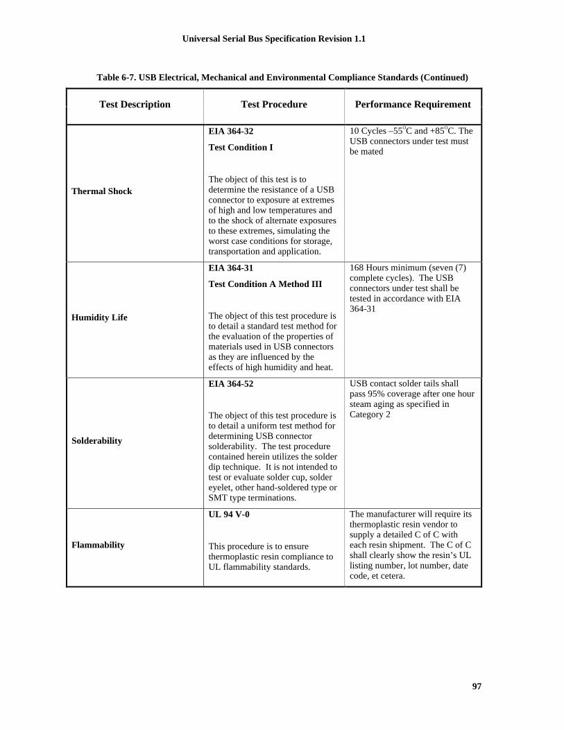
Universal Serial Bus Specification Revision 1.1
97
Table 6-7. USB Electrical, Mechanical and Environmental Compliance Standards (Continued)
Test Description Test Procedure Performance Requirement
Thermal Shock
EIA 364-32
Test Condition I
The object of this test is todetermine the resistance of a USBconnector to exposure at extremesof high and low temperatures andto the shock of alternate exposuresto these extremes, simulating theworst case conditions for storage,transportation and application.
10 Cycles –55OC and +85OC. TheUSB connectors under test mustbe mated
Humidity Life
EIA 364-31
Test Condition A Method III
The object of this test procedure isto detail a standard test method forthe evaluation of the properties ofmaterials used in USB connectorsas they are influenced by theeffects of high humidity and heat.
168 Hours minimum (seven (7)complete cycles). The USBconnectors under test shall betested in accordance with EIA364-31
Solderability
EIA 364-52
The object of this test procedure isto detail a uniform test method fordetermining USB connectorsolderability. The test procedurecontained herein utilizes the solderdip technique. It is not intended totest or evaluate solder cup, soldereyelet, other hand-soldered type orSMT type terminations.
USB contact solder tails shallpass 95% coverage after one hoursteam aging as specified inCategory 2
Flammability
UL 94 V-0
This procedure is to ensurethermoplastic resin compliance toUL flammability standards.
The manufacturer will require itsthermoplastic resin vendor tosupply a detailed C of C witheach resin shipment. The C of Cshall clearly show the resin’s ULlisting number, lot number, datecode, et cetera.

Universal Serial Bus Specification Revision 1.1
98
Table 6-7. USB Electrical, Mechanical and Environmental Compliance Standards (Continued)
Test Description Test Procedure Performance Requirement
Cable ImedanceOnly required for Full-speed
The object of this test is to insurethe signal conductors have theproper impedance.
1. Connect the Time DomainReflectometer (TDR) outputsto the impedance/delay/skewtest fixture (Note 1). Useseparate 50 Ohm cables for theplus (or true) and minus (orcomplement) outputs. Set theTDR head to differential TDRmode.
2. Connect the Series "A" plug ofthe cable to be tested to thetext fixture, leaving the otherend open-circuited.
3. Define a waveform composedof the difference between thetrue and complementwaveforms, to allowmeasurement of differentialimpedance.
4. Measure the minimum andmaximum impedances foundbetween the connector and theopen circuited far end of thecable.
Impedance must be in the rangespecified in Table 7-9 (ZO).

Universal Serial Bus Specification Revision 1.1
99
Table 6-7. USB Electrical, Mechanical and Environmental Compliance Standards (Continued)
Test Description Test Procedure Performance Requirement
Signal Pair Attenuation
Only required for Full-speed
The object of this test is to insurethat adequate signal strength ispresented to the receiver tomaintain a low error rate.
1. Connect the NetworkAnalyzer output port (port 1)to the input connector on theattenuation test fixture (Note2).
2. Connect the Series “A” plugof the cable to be tested to thetest fixture, leaving the otherend open-circuited.
3. Calibrate the network analyzerand fixture using theappropriate calibrationstandards, over the desiredfrequency range.
4. Follow the method listed inHewlett Packard ApplicationNote 380-2 to measure theopen-ended response of thecable.
5. Short circuit the Series “B”end (or bare leads end, if acaptive cable), and measurethe short-circuit response.
6. Using the software in H-PApp. Note 380-2 orequivalent, calculate the cableattenuation, accounting forresonance effects in the cableas needed.
Refer to Section 7.1.17 forfrequency range and allowableattenuation.
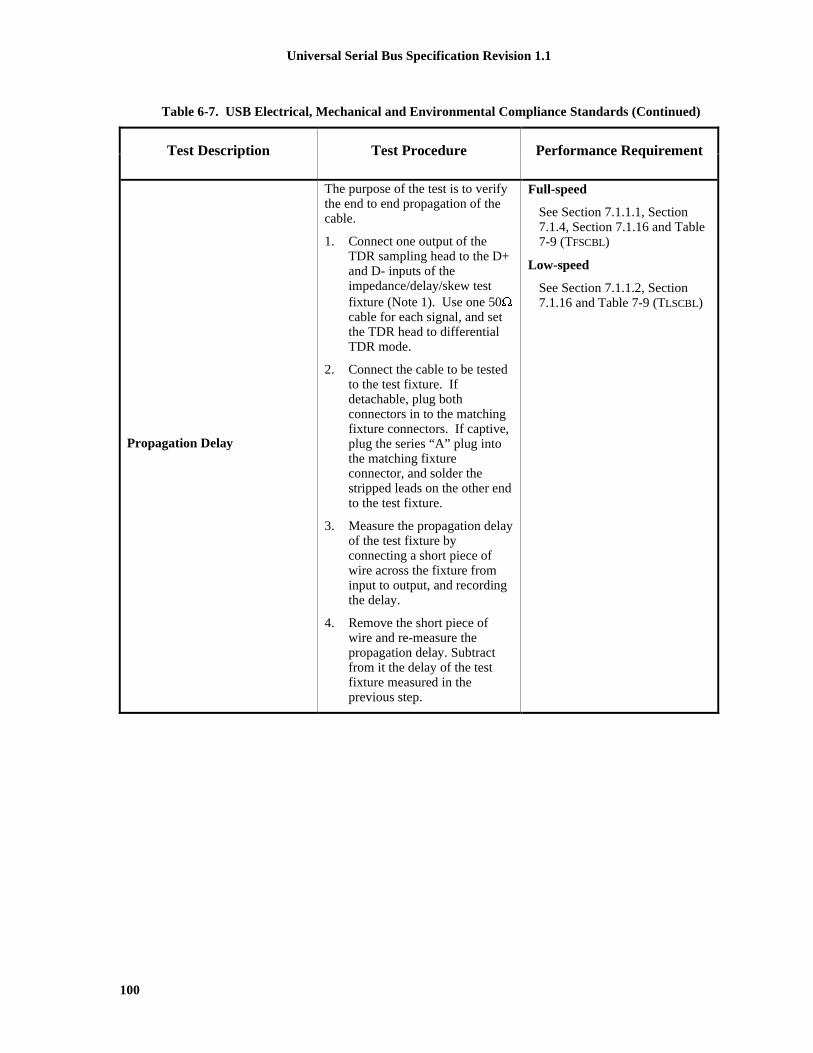
Universal Serial Bus Specification Revision 1.1
100
Table 6-7. USB Electrical, Mechanical and Environmental Compliance Standards (Continued)
Test Description Test Procedure Performance Requirement
Propagation Delay
The purpose of the test is to verifythe end to end propagation of thecable.
1. Connect one output of theTDR sampling head to the D+and D- inputs of theimpedance/delay/skew testfixture (Note 1). Use one 50�cable for each signal, and setthe TDR head to differentialTDR mode.
2. Connect the cable to be testedto the test fixture. Ifdetachable, plug bothconnectors in to the matchingfixture connectors. If captive,plug the series “A” plug intothe matching fixtureconnector, and solder thestripped leads on the other endto the test fixture.
3. Measure the propagation delayof the test fixture byconnecting a short piece ofwire across the fixture frominput to output, and recordingthe delay.
4. Remove the short piece ofwire and re-measure thepropagation delay. Subtractfrom it the delay of the testfixture measured in theprevious step.
Full-speed
See Section 7.1.1.1, Section7.1.4, Section 7.1.16 and Table7-9 (TFSCBL)
Low-speed
See Section 7.1.1.2, Section7.1.16 and Table 7-9 (TLSCBL)

Universal Serial Bus Specification Revision 1.1
101
Table 6-7. USB Electrical, Mechanical and Environmental Compliance Standards (Continued)
Test Description Test Procedure Performance Requirement
Propagation Delay Skew
This test insures that the signal onboth the D+ and D- lines arrive atthe receiver at the same time.
1. Connect the TDR to thefixture with test samplecable, as in the previoussection.
2. Measure the difference indelay for the two conductorsin the test cable. Use theTDR cursors to find theopen-circuited end of eachconductor (where theimpedance goes infinite),and subtract the timedifference between the twovalues.
Propagation skew must meetthe requirements as listed inSection 7.1.3.
Capacitive Load
Only required for Low-speed
The purpose of this test is to insurethe distributed inter-wirecapacitance is less then the lumpedcapacitance specified by the Low-speed transmit driver.
1. Connect the one lead of theImpedance Analyzer to the D+pin on theimpedance/delay/skew fixture(Note 1), and the other lead tothe D- pin.
2. Connect the series "A" plug tothe fixture, with the series “B”end leads open-circuited.
3. Set the Impedance Analyzer toa frequency of 100 kHz, tomeasured the capacitance.
See Section 7.1.1.2 and Table7-7 (CLINUA )
Note1: Impedance, propagation delay and skew test fixture.This fixture will be used with the TDR for measuring the time domain performance of the cable under test.The fixture impedance should be matched to the equipment, typically 50�. Coaxial connectors should beprovided on the fixture for connection from the TDR.
Note 2: Attenuation text fixtureThis fixture provides a means of connection from the network analyzer to the Series "A" plug. Since USBsignals are differential in nature and operate over balanced cable, a transformer or balun (North HillsNH13734 or equivalent) is ideally used. The transformer converts the unbalanced (also known as single-ended) signal from the signal generator which is typically a 50� output, to the balanced (also known asdifferential) and likely different impedance loaded presented by the cable. A second transformer or balun

Universal Serial Bus Specification Revision 1.1
102
should be used on the other end of the cable under test, to convert the signal back to unbalanced from of thecorrect impedance to match the network analyzer.
6.7.1 Applicable DocumentsAmerican National Standard/Electronic Industries Association
ANSI/EIA-364-C (12/94) Electrical Connector/Socket Test ProceduresIncluding Environmental Classifications
American Standard Test Materials
ASTM-D-4565 Physical and Environmental Performance Propertiesof Insulation and Jacket for TelecommunicationWire and Cable, Test Standard Method
ASTM-D-4566 Electrical Performance Properties of Insulation andJacket for Telecommunication Wire and Cable, TestStandard Method
Underwriters’ Laboratory, Inc.
UL STD-94 Test for Flammability of Plastic materials for Partsin Devices and Appliances
UL Subject-444 Communication Cables
6.8 USB GroundingThe shield must be terminated to the connector plug for completed assemblies. The shield and chassisare bonded together. The user selected grounding scheme for USB devices and cables must be consistentwith accepted industry practices and regulatory agency standards for safety and EMI/ESD/RFI.
6.9 PCB Reference DrawingsThe following drawings describe typical receptacle PCB interfaces. This is included for informationpurposes only.

Universal Serial Bus Specification Revision 1.1
103
NOTES:
1. Cri t ical Dimensions are TOLERANCED and should not be deviated.
2. Dimensions that are labeled REF aretypical d imensions and may vary f rommanufacturer to manufacturer .
3. Al l d imens ions a re in m i l l ime te rs (m m ) un lessotherwise noted.
2.80 + 0.10
16.0 REF
13.9 REF
6.5 REF
7.6 REF
3.8 REF
10.3 REF
6.00 + 0.10
2.50 + 0.05
1 2 3 4
10.7 REF9.0 REF
5.12 + 0.10
2.50 + 0.05
2.00 + 0.05
1.84 + 0.05
2.56 + 0.05
12.5 + 0.10
11.1 + 0.10
Thermoplast ic Insulator UL 94-V0
1.0 + 0.05 Wide - Select ively Plated Contact (4)
R 0.64 + 0.13 Typical (2)
2 .0 REF
14.3 REF
13.1 REF
15.0 R E F
SCALE: N/A SHEET 1 of 1
Single Pin-Type
Series "A" ReceptacleSIZE DRAWING NUMBER REV
A N/ADATE
2/98 C
H
G
F
E
D
C
B
A
8 7 6 5 4 3 2 1
H
G
F
E
D
C
B
A
8 7 6 5 4 3 2 1
Printed Circuit Board (PCB) Layout
7.00 + 0.10
2.00 + 0.10
13.14 + 0.10
2.71 + 0.10
Ø 0.92 + 0.10 (4)
Ø 2.30 + 0.10 (2)
���������������� ���
Figure 6-12. Single Pin-Type Series "A" Receptacle
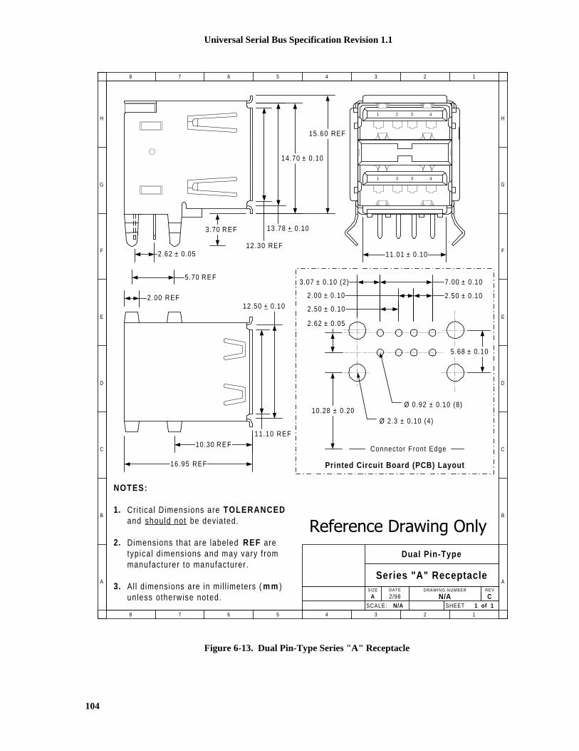
Universal Serial Bus Specification Revision 1.1
104
C
Dual Pin-Type
Series "A" ReceptacleSIZE DRAWING NUMBER REV
A N/ADATE
2/98
SHEET 1 of 1SCALE: N/A
NOTES:
1. Cri t ical Dimensions are TOLERANCED and should not be deviated.
2. Dimensions that are labeled REF aretypical d imensions and may vary f rommanufacturer to manufacturer .
3. All dimensions are in mi l l imeters ( m m )unless otherwise noted.
H
G
F
E
D
C
B
A
8 7 6 5 4 3 2 1
H
G
F
E
D
C
B
A
8 7 6 5 4 3 2 1
16.95 REF
10.30 R E F11.10 REF
12.50 + 0.10
3.70 R E F
15.60 REF
14.70 ± 0.10
12.30 REF
2.00 REF
2.62 ± 0.05
5.70 R E F
13.78 + 0.10
1 2 3 4
1 2 3 4
11.01 ± 0.10
2.62 ± 0.05
3.07 ± 0.10 (2) 7.00 ± 0.10
2.00 ± 0.10 2.50 ± 0.10
5.68 ± 0.10
10.28 ± 0.20Ø 2.3 ± 0.10 (4)
Ø 0.92 ± 0.10 (8)
Connector Front Edge
Printed Circuit Board (PCB) Layout
2.50 ± 0.10
���������������� ���
Figure 6-13. Dual Pin-Type Series "A" Receptacle

Universal Serial Bus Specification Revision 1.1
105
SCALE: N/A
Single Pin-Type
Series "B" ReceptacleSIZE DRAWING NUMBER REV
A N/ADATE
2/98 CSHEET 1 of 1
NOTES:
1. Cri t ical Dimensions are TOLERANCED and should not be deviated.
2. Dimensions that are labeled REF aretypical d imensions and may vary f rommanufacturer to manufacturer .
3. All dimensions are in mi l l imeters ( m m )unless otherwise noted.
H
G
F
E
D
C
B
A
8 7 6 5 4 3 2 1
H
G
F
E
D
C
B
A
8 7 6 5 4 3 2 1
3.50 R E F
1.0 + 0.05 Wide - Select ively Plated Contacts (4) ....
Thermoplast ic Insulator UL 94-V0 ....
12
43
2.50 + 0.108.45 + 0.10
7.78 + 0.10
5.60 + 0.10
11.50 R E F
3.01 + 0.10
16.00 R E F
2.71 + 0.10
4.71 + 0.10
10.30 R E F
2.00 + 0.10
12.00 R E F
2.50 + 0.10
12.04 + 0.10
2.00 + 0.10
Ø 0.92 + 0.1 (4)
Ø 2.30 + 0.1 (2)
2.71 + 0.10
4.77 + 0.10
Printed Circuit Board (PCB) Layout
���������������� ���
Figure 6-14. Single Pin-Type Series "B" Receptacle

Universal Serial Bus Specification Revision 1.1
106

Universal Serial Bus Specification Revision 1.1
107
Chapter 7Electrical
This chapter describes the electrical specification for the USB. It contains signaling, power distribution,and physical layer specifications.
7.1 SignalingThe signaling specification for the USB is described in the following subsections.
7.1.1 USB Driver CharacteristicsThe USB uses a differential output driver to drive the USB data signal onto the USB cable. The staticoutput swing of the driver in its low state must be below VOL (max) of 0.3V with a 1.5k� load to 3.6V andin its high state must be above the VOH (min) of 2.8V with a 15k� load to ground as listed in Table 7-5.Full-speed drivers have more stringent requirements, as described in Section 7.1.1.1. The output swingsbetween the differential high and low state must be well-balanced to minimize signal skew. Slew ratecontrol on the driver is required to minimize the radiated noise and cross talk. The driver’s outputs mustsupport three-state operation to achieve bi-directional half-duplex operation.
USB devices must be capable of withstanding continuous exposure to the waveforms shown in Figure 7-1while in any drive state. These waveforms are applied directly into each USB data pin from a voltagesource with an output impedance of 39�. The open-circuit voltage of the source shown in Figure 7-1 isbased on the expected worst-case overshoot and undershoot.
It is recommended that these DC and AC stresses be used as qualification criteria against which the long-term reliability of each device is evaluated.
60nS(min)
166.7ns(6MHz)
4-20ns
4.6V
-1.0V
D+ or D- pinon USB connector
nearest device
USBDevice
Evaluation Setup
The signal produced by the voltage generator may bedistorted when observed at the data pin due to inputprotection devices possibly incorporated in the USB
device.
RSRC = 39�� ��2%
RSRC
V
Figure 7-1. Maximum Input Waveforms for USB Signaling
A USB device must be able to withstand a continuous short circuit of D+ and D- to VBUS, GND, other dataline, or the cable shield at the connector. The device must not be damaged when presented with a drivingsignal that provides a duty cycle of 50% transmit and 50% receive. The transmit phase consists of asymmetrical signal that toggles between drive high and drive low. This requirement must be met for maxvalue of VBUS.

Universal Serial Bus Specification Revision 1.1
108
7.1.1.1 Full-speed (12Mb/s) Driver CharacteristicsA full-speed USB connection is made through a shielded, twisted pair cable with a characteristicimpedance (Z0) of 90� �15% and a maximum one-way delay of 26ns. The impedance of each of thedrivers (ZDRV) must be between 28� and 44� i.e. within the grey area in Figure 7-3.
For a CMOS implementation, the driver impedance will typically be realized by a CMOS driver with animpedance significantly less than this resistance with a discrete series resistor making up the balance asshown in Figure 7-2. The series resistor RS is included in the buffer impedance requirement shown inFigure 7-3. In the rest of the chapter, references to the buffer assume a buffer with the series impedanceunless stated otherwise.
RS
Buffer Output Imped. (Z BUF)
D+ (28� to 44� Equiv. Imped.)
OE
TxD+
Identical CMOS Buffers
RS
D- (28� to 44� Equiv. Imped.)TxD-
Figure 7-2. Example Full-speed CMOS Driver Circuit
The buffer impedance must be measured for driving high as well as driving low. Figure 7-3 shows thecomposite V/I characteristics for the full-speed drivers with included series damping resistor (RS). Thecharacteristics are normalized to the steady-state, unloaded output swing of the driver. The normalizeddriver characteristics are found by dividing the measured voltages and currents by the actual swing of thedriver under test. The normalized V/I curve for the driver must fall entirely inside the shaded region. TheV/I region is bounded by the minimum driver impedance above and the maximum driver impedancebelow. The minimum drive region is intersected by a constant current region of |6.1VOH|mA when drivinglow and -|6.1VOH|mA when driving high. This is the minimum current drive level necessary to ensure thatthe waveform at the receiver crosses the opposite single-ended switching level on the first reflection.
When testing, the current into or out of the device need not exceed �10.71*VOH mA and the voltageapplied to D+/D- need not exceed 0.3*VOH for the drive low case and need not drop below 0.7*VOH forthe drive high case.

Universal Serial Bus Specification Revision 1.1
109
2.32
6.1 * |VOH|
VOH0.27*VOH0.3V00
Slope = 1/44�
Slope = 1/28�
drive low
VOUT (Volts)
IOUT(mA)
Slope = 1/44�
Slope = 1/28�
drive hi gh
IOUT(mA)
-6.1*|VOH|
VOH0.73*VOH0
0
VOUT (Volts)
10.71 * |VOH|
0.3*VOH
0.7*VOH
-10.71 * |VOH|
Test Limit
Test Limit
Figure 7-3. Full-speed Buffer V/I Characteristics

Universal Serial Bus Specification Revision 1.1
110
Figure 7-4 shows the full-speed driver signal waveforms.
VSS
One BitTime
(12Mb/s)
DriverSignal Pins
One-WayTrip Cable
Delay
VSS
Signal pins passinput spec levelsafter one cable
delay
ReceiverSignal Pins
VIL (max)
VIH (min)
Figure 7-4. Full-speed Signal Waveforms
7.1.1.2 Low-speed (1.5Mb/s) Driver CharacteristicsA low-speed device must have a captive cable with the Series A connector on the plug end. Thecombination of the cable and the device must have a single-ended capacitance of no less than 200pF and nomore than 450pF on the D+ or D- lines.
The propagation delay (TLSCBL) of a low-speed cable must be less than 18ns. This is to ensure that thereflection occurs during the first half of the signal rise/fall, which allows the cable to be approximated by alumped capacitance.
VSS
Signal pinspass outputspec levels
with minimalreflections and
ringing
One BitTime
(1.5Mb/s)
DriverSignal Pins
VIH (min)
VIL (max)
Figure 7-5. Low-speed Driver Signal Waveforms
7.1.2 Data Signal Rise and FallThe output rise time and fall times are measured between 10% and 90% of the signal (Figure 7-6). Riseand fall time requirements apply to differential transitions as well as to transitions between differential andsingle-ended signaling.

Universal Serial Bus Specification Revision 1.1
111
The rise and fall times for full-speed buffers are measured with the load shown in Figure 7-7. The rise andfall times must be between 4ns and 20ns, and matched to within �10% to minimize RFI emissions andsignal skew. The transitions must be monotonic.
The rise and fall times for low-speed buffers are measured with the load shown in Figure 7-8. Thecapacitive load shown in Figure 7-8 is representative of the worst-case load allowed by the specification.A downstream port is allowed 150pF of input/output capacitance (CIND). A low-speed device (includingcable) may have a capacitance of as little as 200pF and as much as 450pF. This gives a range of 200pF to600pF as the capacitive load that a downstream low-speed buffer might encounter. Upstream buffers onlow-speed devices must be designed to drive the capacitance of the attached cable plus an additional150pF. If a low-speed buffer is designed for an application where the load capacitance is known to fall in adifferent range, the test load can be adjusted to match the actual application. Low-speed buffers on hostsand hubs that are attached to USB receptacles must be designed for the 200pF to 600pF range. The riseand fall time must be between 75ns and 300ns for any balanced, capacitive test load. In all cases, the edgesmust be matched to within �20% to minimize RFI emissions and signal skew. The transitions must bemonotonic.
For both full-speed and low-speed signaling, the crossover voltage (VCRS) must be between 1.3V and2.0V.
This specification does not require matching signal swing matching to any greater degree than describedabove. However, when signaling, it is preferred that the average voltage on the D+ and D- lines should beconstant. This means that the amplitude of the signal swing on both D+ and D- should be the same; thelow and high going transition should begin at the same time and change at the same rate; and the crossovervoltage should be the same when switching to a J or K. Deviations from signal matching will result incommon-mode noise that will radiate and affect the ability of devices and systems to pass tests that aremandated by government agencies.
DifferentialData Lines
10%
Rise Time
90%
Fall Time
tR tF
10%
90%VCRS
Figure 7-6. Data Signal Rise and Fall Time
CL = 50pF
TxD-
TxD+
CL
RS
CL
RS
Full-speedBuffer
Figure 7-7. Full-speed Load

Universal Serial Bus Specification Revision 1.1
112
Low-speed Buffer
Low-speed Buffer
CL = 200pF to 600pF
TxD-
TxD+
CL
RS
CL
RS
3.6V
1.5K��
CL = 50pF to 150pF
TxD-
TxD+
CL
RS
CL
RS
15K��
15K��
Low-speed downstream port load Low-speed upstream port load
Figure 7-8. Low-speed Port Loads
Note: the CL for low-speed port load only represents the range of loading that might be added when thelow-speed device is attached to a hub. The low-speed buffer must be designed to drive the load of itsattached cable plus CL. A low-speed buffer design that can drive the downstream port test load would becapable of driving any legitimate upstream load.
7.1.2.1 Driver UsageThe upstream ports (towards the host) of all hubs and full-speed functions must use full-speed drivers.The upstream hub port transmits data at both full- and low-speed data rates. However, the signalingalways uses full-speed signaling conventions and edge rates (refer to Figure 7-13 Upstream Full Speed PortTransceiver and Table 7-1 Signaling Levels). Transmission of low-speed data does not change the driver’scharacteristics. The upstream port of low-speed functions must use a low-speed driver.
External downstream ports of all hubs (including the host), are required to be capable of both drivercharacteristics, such that any type of device can be plugged in to these ports. When the transceiver is infull-speed mode it uses full-speed signaling conventions and edge rates. In low-speed it uses low-speedsignaling conventions and edge rates (refer to Figure 7-14 Downstream Port Transceiver and Table 7-1Signaling Levels).
7.1.3 Cable SkewThe maximum skew introduced by the cable between the differential signaling pair (i.e., D+ and D-(TSKEW)) must be less than 400pS and is measured as described in Section 6.7.
7.1.4 Receiver CharacteristicsA differential input receiver must be used to accept the USB data signal. The receiver must feature aninput sensitivity (VDI) of at least 200mV when both differential data inputs are in the differential commonmode range (VCM) of 0.8V to 2.5V, as shown in Figure 7-9.
In addition to the differential receiver, there must be a single-ended receiver for each of the two data lines.The receivers must have a switching threshold between 0.8V (VIL) and 2.0V (VIH). It is recommended thatthe single-ended receivers incorporate hysteresis to reduce their sensitivity to noise.
Both D+ and D- may temporarily be less than Vih(min) during differential signal transitions. This periodcan be up to 14ns (TFST) for full-speed transitions and up to 210ns (TLST) for low-speed transitions. Logicin the receiver must ensure that that this is not interpreted as an SE0.

Universal Serial Bus Specification Revision 1.1
113
4.6-1.0
Input Voltage Range (volts)
0.0 0.2 0.4 0.6 0.8 1.0 1.2 1.4 1.6 1.8 2.0 2.2 2.4 2.6 2.8 3.0 3.2
Differential OutputCrossover
Voltage Range
Differential Input Voltage Range
Figure 7-9. Differential Input Sensitivity Range
7.1.5 Device Speed IdentificationThe USB is terminated at the hub and function ends as shown in Figure 7-10 and Figure 7-11. Full-speedand low-speed devices are differentiated by the position of the pull-up resistor on the downstream end ofthe cable:
� Full-speed devices are terminated as shown in Figure 7-10 with the pull-up resistor on the D+ line.
� Low-speed devices are terminated as shown in Figure 7-11 with the pull-up resistor on the D- line.
� The pull-down terminators on downstream ports are resistors of 15k� �5% connected to ground.
The design of the pull-up resistor must ensure that the signal levels satisfy the requirements specified inTable 7-1. In order to facilitate bus state evaluation that may be performed at the end of a reset, the designmust be able to pull-up D+ or D- from 0V to VIH (min) within the minimum reset relaxation time of 2.5�s.A device that has a detachable cable must use a 1.5k� �5% resistor tied to a voltage source between 3.0Vand 3.6V (VTERM) to satisfy these requirements. Devices with captive cables may use alternativetermination means. However, the Thevenin resistance of any termination must be no less than 900�.
Note: Thevenin resistance of termination does not include the 15k� �5% resistor on host/hub.
The voltage source on the pull-up resistor must be derived from or controlled by the power supplied on theUSB cable such that when VBUS is removed, the pull-up resistor does not supply current on the data line towhich it is attached.
Full-speed orLow-speed USB
Transceiver
Host orHub Port
Rpd
D+
D-D-
D+
Rpd
Full-speed USBTransceiver
Hub Upstream Portor
Full-speed Function
Z 0=90�� ��15%
Rpd=15K�� ��5%
Rpu=1.5K�� ��5%
Rpu
Figure 7-10. Full-speed Device Cable and Resistor Connections

Universal Serial Bus Specification Revision 1.1
114
Full-speed orLow-speed USB
Transceiver
Host orHub Port
Rpd
D+
D-D-
D+
Rpd
Slow Slew RateBuffers
Low-speed USBTransceiver
Low-speed Function
Rpd=15K�� ��5%
Rpu=1.5K�� ��5% (nominal )
Rpu
Figure 7-11. Low-speed Device Cable and Resistor Connections
7.1.6 Input CharacteristicsThe input impedance of D+ or D- without termination should be � 300 k� (ZINP). The input capacitance ofa port is measured at the connector pins. Upstream and downstream ports are allowed different values ofcapacitance. The maximum capacitance (differential or single-ended) (CIND) allowed on a downstreamport of a hub or host is 150pF on D+ or D-. This is comprised of up to 75pF of lumped capacitance toground on each line at the transceiver and in the connector, and an additional 75pF capacitance on eachconductor in the transmission line between the receptacle and the transceiver. The transmission linebetween the receptacle and RS must be 90� �15%).
The maximum capacitance on an upstream port of a full-speed device with a detachable cable (CINUB) is100pF on D+ or D- . This is comprised of up to 75 pF of lumped capacitance to ground on each line at thetransceiver and in the connector, and an additional 25pF capacitance on each conductor in the transmissionline between the receptacle and the transceiver. The difference in capacitance between D+ and D- must beless than 10%.
For full-speed devices with captive cables, the device itself may have up to 75pF of lumped capacitance toground on on D+ and D-. The cable accounts for the remainder of the input capacitance .
A low-speed device is required to have a captive cable. The input capacitance of the low-speed device willinclude the cable. The maximum single-ended or differential input capacitance of a low-speed device is450pF (CLINUA ).
For devices with captive cables, the single-ended input capacitance must be consistent with the terminationscheme used. The termination must be able to charge the D+ or D- line from 0V to VIH (min) within 2.5�s.The capacitance on D+/D- includes the single-ended input-capacitance of the device (measured from thepins on the connector on the cable) and the 150pF of input capacitance of the host/hub.
An implementation may use small capacitors at the transceiver for purposes of edge rate control. The sumof the capacitance of the added capacitor (CEDGE) , the transceiver, and the trace connecting capacitor andtransceiver to RS must not exceed 75pF (either single-ended or differential) and the capacitance must bebalanced to within 10%. The added capacitor, if present, must be placed between the transceiver pins andRS (see Figure 7-12).
Use of ferrite beads on the D+ or D- lines of full-speed devices is discouraged.

Universal Serial Bus Specification Revision 1.1
115
TxD-
TxD+
RS
RS
CEDGE
CEDGE
Figure 7-12. Placement of Optional Edge Rate Control Capacitors
7.1.7 Signaling LevelsTable 7-1 summarizes the USB signaling levels. The source is required to drive the levels specified in thesecond column and the target is required to identify the correct bus state when it sees the levels in thethird column. (Target receivers can be more sensitive as long as they are within limits specified in thefourth column).

Universal Serial Bus Specification Revision 1.1
116
Table 7-1. Signaling Levels
Bus State Signaling Levels
At final target connectorAt originating sourceconnector (at end of bit time) Required Acceptable
Differential “1” D+ > VOH (min) and D- < VOL (max) (D+) - (D-) � 200mVand D+ � VIH (min)
(D+) - (D-) � 200mV
Differential “0” D- > VOH (min) and D+ < VOL (max) (D-) - (D+) > 200mVand D- � VIH (min)
(D-) - (D+) > 200mV
Single-ended 0 (SE0) D+ and D- < VOL (max) D+ and D- < VIL (max) D+ and D- < VIH (min)
Data J state:
Low-speed
Full-speed
Differential “0”
Differential “1”
Differential “0”
Differential “1”
Data K state:
Low-speed
Full-speed
Differential “1”
Differential “0”
Differential “1”
Differential “0”
Idle state:
Low-speed
Full-speed
N.A.
D- > VIHZ (min) and
D+ < VIL (max)
D+ > VIHZ (min) and
D- < VIL (max)
D- > VIHZ (min) and
D+ < VIH (min)
D+ > VIHZ (min) and
D- < VIH (min)
Resume state Data K state Data K state
Start-of-Packet (SOP) Data lines switch from Idle to K state
End-of-Packet (EOP)4 SE0 for approximately 2 bit times1
followed by a J for 1 bit time3
SE0 for � 1 bit time2
followed by a J statefor 1 bit time
SE0 for � 1 bit time2
followed by a J state
Disconnect(at downstream port)
N.A. SE0 for �2.5�s
Connect(at downstream port)
N.A. Idle for �2ms Idle for �2.5 �s
Reset D+ and D- � VOL (max) for �10ms D+ and D- � VIL (max)for �10ms
D+ and D- � VIL (max)for �2.5 �s
Note 1: The width of EOP is defined in bit times relative to the speed of transmission. (Specification EOP widths aregiven in Table 7-5 and Table 7-6.)
Note 2: The width of EOP is defined in bit times relative to the device type receiving the EOP. The bit time isapproximate.
Note 3: The width of the J state following the EOP is defined in bit times relative to the buffer edge rate. The J state froma low-speed buffer must be a low-speed bit time wide and from a full-speed buffer, a full-speed bit time wide.
Note 4: The keep-alive is a low-speed EOP.

Universal Serial Bus Specification Revision 1.1
117
The J and K data states are the two logical levels used to communicate differential data in the system.Differential signaling is measured from the point where the data line signals cross over. Differential datasignaling is not concerned with the level at which the signals cross, as long as the crossover voltage meetsthe requirements in Section 7.1.2. Note that, at the receiver, the Idle and Resume states are logicallyequivalent to the J and K states respectively.
As shown in Table 7-1, the J and K states for full-speed signaling are inverted from those for low-speedsignaling. The sense of data, idle, and resume signaling is set by the type of device that is being attached toa port. If a full-speed device is attached to a port, that segment of the USB uses full-speed signalingconventions (and fast rise and fall times), even if the data being sent across the data lines is at the low-speed data rate. The low-speed signaling conventions shown in Table 7-1 (plus slow rise and fall times)are used only between a low-speed device and the port to which it is attached.
D+
D-Differential Receiver
Single-ended Receivers
Output Buffers
3.0V��V��3.6V
1.5K�� ��������
or equivalent
RxD
RxD+
RxD-
OE
TxD+
TxD-
Figure 7-13. Upstream Full-speed Port Transceiver
D+
D-Differential Receiver
Single-ended Receivers
Output Buffers
15K�� ��������
RxD
RxD+
RxD-
OE
TxD+
TxD-
Speed
Note: additional logic is requiredto invert signal polarity ondata in/out when low-speeddevices are attached.
Figure 7-14. Downstream Port Transceiver

Universal Serial Bus Specification Revision 1.1
118
7.1.7.1 Connect and Disconnect SignalingWhen no function is attached to the downstream port of the host or hub, the pull-down resistors presentthere will cause both D+ and D- to be pulled below the single-ended low threshold of the host or hub portwhen that port is not being driven by the hub. This creates an SE0 state on the downstream port. Adisconnect condition (TDDIS) is indicated if the host or hub is not driving the data lines and an SE0 persistson a downstream port for more than 2.5�s (see Figure 7-15).
A connect condition (TDCNN) will be detected when the hub detects that one of the data lines is pulledabove its VIH threshold for more than 2.5�s (see Figure 7-16 and Figure 7-17).
Hubs may optionally determine the speed of the attached device by sampling the state of the busimmediately before driving SE0 to indicate a reset condition to the device. Alternatively, the hub may floatthe bus after driving reset and perform bus state evaluation after 2.5�s as shown in Figure 7-18.
All signaling levels given in Table 7-1 are set for this bus segment (and this segment alone) once the speedof the attached device is determined. The mechanics of speed detection are described in Section 11.8.2.
D-/D+
D+/D-
VIHZ (min )
VIL
VSS
DeviceDisconnected
DisconnectDetected
�� 2.5��S
Figure 7-15. Disconnect Detection
VIH
VSS
DeviceConnected
D-
D+
ConnectDetected
�� 2.5��S
Figure 7-16. Full-speed Device Connect Detection

Universal Serial Bus Specification Revision 1.1
119
VIH
VSS
DeviceConnected
D+
D-
ConnectDetected
�� 2.5��s
Figure 7-17. Low-speed Device Connect Detection
VOH(min)
VIH(min)
VIL(max)
VOL(max)
VSS
Reset completedand bus is floated
Bus evaluated after reset:Diff 1 = FS connectedDiff 0 = LS connectedSE0 = Disconnected
�� 2.5��s�� 10ms
Port drivingreset
Diff 1 orDiff 0
SE0
Differentialdata lines
VIL
Figure 7-18. Bus State Evaluation after reset (optional)
Because USB components may be hot plugged, and hubs may implement power switching, it is necessaryto comprehend the delays between power switching and/or device attach and when the device’s internalpower has stabilized. Figure 7-19 shows all the events associated with both turning on port power with adevice connected and hot-plugging a device. There are six delays and a sequence of events that are definedby this specification.

Universal Serial Bus Specification Revision 1.1
120
�t1
100ms�t2
�4.01V
D+orD-
100ms�t3
Hub portpower-on
Hub portpower OK
Attach Detected
�t4 �t5 USB System Softwarereads device speed
VIH(min)
10ms
Reset RecoveryTime
�t6
VBUS
VIH
Figure 7-19. Power-on and Connection Events Timing
��t1 This is the amount of time required for the hub port power switch to operate. This delay is afunction of the type of hub port switch. Hubs report this time in the hub descriptor (see Section11.15.2.1), which can be read via a request to the Hub Controller (see Section 11.16.2.4). If adevice were plugged into a non-switched or already-switched on port, �t1 is equal to zero.
��t2 (TSIGATT)This is the maximum time from when VBUS is up to valid level (4.01V) to when a devicehas to signal attach. �t2 represents the time required for the device’s internal power rail to stabilizeand for D+ or D- to reach VIH (min) at the hub. �t2 must be less than 100ms for all hub and deviceimplementations. (This requirement only applies if the device is drawing power from the bus).
��t3 (TATTDB) This is a debounce interval with a minimum duration of 100ms that is provided by the USBSystem Software. It ensures that the electrical and mechanical connection is stable before softwareattempts to reset the attached device. The interval starts when the USB System Software is notifiedof a connection detection. The interval restarts if there is a disconnect. The debounce intervalensures that power is stable at the device for at least 100ms before any requests will be sent to thedevice.
��t4 (T2SUSP) Anytime a device observes no bus activity, it must obey the rules of going into suspend (seeSection 7.1.7.4).
��t5 (TDRST) This is the period of time hubs drive reset to a device. Refer to Section 11.5.1.5 for details.
��t6 (TRSTRCY) The USB System Software guarantees a minimum of 10ms for reset recovery. Deviceresponse to any bus transactions addressed to the default device address during the reset recoverytime is undefined.

Universal Serial Bus Specification Revision 1.1
121
7.1.7.2 Data SignalingData transmission within a packet is done with differential signals.
The start of a packet (SOP) is signaled by the originating port by driving the D+ and D- lines from the Idlestate to the opposite logic level (K state). This switch in levels represents the first bit of the SYNC field.Hubs must limit the change in the width of the first bit of SOP when it is retransmitted to less than �5ns.Distortion can be minimized by matching the nominal data delay through the hub with the output enabledelay of the hub.
The SE0 state is used to signal an end-of-packet (EOP). EOP will be signaled by driving D+ and D- to theSE0 state for two bit times followed by driving the lines to the J state for one bit time. The transition fromthe SE0 to the J state defines the end of the packet at the receiver. The J state is asserted for one bit timeand then both the D+ and D- output drivers are placed in their high-impedance state. The bus terminationresistors hold the bus in the Idle state. Figure 7-20 shows the signaling for start and end of a packet.
VOH(min )
VIL(max)VOL(max)
VSS
VIH(min )
Bus IdleFirst Bit
of PacketSOP
VOH(min)
VIL(max)VOL(max)
VSS
VIH(min)
Last Bitof Packet
Bus Driven toJ State at end
of EOP
Bus Idle
BusFloats
SE0portionof EOP
Figure 7-20. Packet Voltage Levels

Universal Serial Bus Specification Revision 1.1
122
7.1.7.3 Reset SignalingA hub signals reset to a downstream port by driving an extended SE0 at the port. After the reset isremoved, the device will be in the Default state (refer to Section 9.1).
The reset signaling can be generated on any Hub or Host Controller port by request from the USB SystemSoftware. The reset signaling must be driven for a minimum of 10ms (TDRST). After the reset, the hubport will transition to the Enabled state (refer to Section 11.5). Host Controllers and the USB SystemSoftware must ensure that resets issued to the root ports drive reset long enough to overwhelm anyconcurrent resume attempts by downstream devices. Resets from root ports should be nominally 50ms(TDRSTR). It is not required that this be 50ms of continuous Reset signaling. However, if the reset is notcontinuous, the interval(s) between signaling reset must be less than 3ms (TRHRSI).
A device seeing an SE0 on its upstream port for more than 2.5�s (TDETRST) may treat that signal as areset. The reset must have taken effect before the reset signaling ends.
Hubs will propagate traffic to a newly reset port after the port is in the Enabled state. The device attachedto this port must recognize this bus activity and keep from going into the Suspend state.
Hubs must be able to accept all hub requests and devices must be able to accept a SetAddress() request(refer to Section 11.16.2 and Section 9.4 respectively) after the reset recovery time 10ms (TRSTRCY) afterthe reset is removed. Failure to accept this request may cause the device not to be recognized by the USBsystem software. Hubs and devices must complete commands within the times specified in Chapter 9 andChapter 11.
Reset must wake a device from the Suspend state.
7.1.7.4 SuspendingAll devices must support the Suspend state. Devices can go into the Suspend state from any powered state.They begin the transition to the Suspend state after they see a constant Idle state on their upstream bus linesfor more than 3.0ms. The device must actually be suspended, drawing only suspend current from the busafter no more than 10ms of bus inactivity on all its ports. Any bus activity on the upstream port will keep adevice out of the Suspend state. In the absence of any other bus traffic, the SOF token (refer toSection 8.4.2) will occur once per frame to keep full-speed devices from suspending. In the absence of anylow-speed traffic, low-speed devices will see at least one keep-alive (defined in Table 7-1) in every framein which an SOF occurs, which keeps them from suspending. Hubs generate this keep-alive as described inSection 11.8.4.1.
While in the Suspend state, a device must continue to provide power to its D+ (full-speed) or D- (low-speed) pull-up resistor to maintain an idle so that the upstream hub can maintain the correct connectivitystatus for the device.
7.1.7.4.1 Global SuspendGlobal suspend is used when no communication is desired anywhere on the bus and the entire bus is placedin the Suspend state. The host signals the start of global suspend by ceasing all its transmissions (includingthe SOF token). As each device on the bus recognizes that the bus is in the Idle state for the appropriatelength of time, it goes into the Suspend state.
7.1.7.4.2 Selective SuspendSegments of the bus can be selectively suspended by sending the commandSetPortFeature(PORT_SUSPEND) to the hub port to which that segment is attached. The suspended portwill block activity to the suspended bus segment and devices on that segment will go into the Suspend stateafter the appropriate delay as described above.

Universal Serial Bus Specification Revision 1.1
123
Section 11.5 describes the port Suspend state and its interaction with the port state machine. Suspend isfurther described in Section 11.9.
7.1.7.5 ResumeIf a device is in the Suspend state, its operation is resumed when any non-idle signaling is received on itsupstream port. Additionally, the device can signal the system to resume operation if its remote wakeupcapability has been enabled by the USB System Software. Resume signaling is used by the host or adevice to bring a suspended bus segment back to the active condition. Hubs play an important role in thepropagation and generation of resume signaling. The following description is an outline of a generalglobal resume sequence. A complete description of the resume sequence, the special cases caused byselective suspend, and the role of the hub are given in Section 11.9.
The host may signal resume (TDRSMDN) at any time. It must send the resume signaling for at least 20msand then end the resume signaling with a standard, low-speed EOP (two low-speed bit times of SE0followed by a J). The 20ms of resume signaling ensures that all devices in the network that are enabled tosee the resume are awakened. The EOP tears down the connectivity established by the resume signalingand prepares the hubs for normal operation. After resuming the bus, the host must begin sending bustraffic (at least the SOF token) within 3ms to keep the system from going back into the Suspend state.
A device with remote wakeup capability may not generate resume signaling unless the bus has beencontinuously in the Idle state for 5ms (TWTRSM). This allows the hubs to get into their Suspend state andprepare for propagating resume signaling. The remote wakeup device must hold the resume signaling forat least 1ms but for no more than 15ms (TDRSMUP). At the end of this period, the device stops driving thebus (puts its drivers into the high-impedance state and does not drive the bus to the J state).
If the hub upstream of a remote wakeup device is suspended, it will propagate the resume signaling to itsupstream port and to all of its enabled downstream ports, including the port that originally signaled theresume. The hub must begin this rebroadcast (TURSM) of the resume signaling within 100�s of receivingthe original resume. The resume signal will propagate in this manner upstream until it reaches the host or anon-suspended hub (refer to Section 11.9), which will reflect the resume downstream and take control ofresume timing. This hub is termed the controlling hub. Intermediate hubs (hubs between the resumeinitiator and the controlling hub) drive resume (TDRSMUP) on their upstream port for at least 1ms duringwhich time they also continue to drive resume on enabled downstream ports. An intermediate hub willstop driving resume on the upstream port and reverse the direction of connectivity from upstream todownstream within 15ms after first asserting resume on its upstream port. When all intermediate hubshave reversed connectivity, resume is being driven from the controlling hub through all intermediate hubsand to all enabled ports. The controlling hub must rebroadcast the resume signaling within 100�s(TURSM) and ensures that resume is signaled for at least 20ms (TDRSMDN). The hub may then beginnormal operation by terminating the resume process as described above.
The USB System Software must provide a 10ms resume recovery time (TRSMRCY) during which it will notattempt to access any device connected to the affected (just-activated) bus segment.
Port connects and disconnects can also cause a hub to send a resume signal and awaken the system. Theseevents will cause a hub to send a resume signal only if the hub has been enabled as a remote-wakeupsource. Refer to Section 11.4.4 for more details.
Refer to Section 7.2.3 for a description of power control during suspend and resume.
7.1.8 Data Encoding/DecodingThe USB employs NRZI data encoding when transmitting packets. In NRZI encoding, a “1” is representedby no change in level and a “0” is represented by a change in level. Figure 7-21 shows a data stream andthe NRZI equivalent. The high level represents the J state on the data lines in this and subsequent figuresshowing NRZI encoding. A string of zeros causes the NRZI data to toggle each bit time. A string of onescauses long periods with no transitions in the data.

Universal Serial Bus Specification Revision 1.1
124
� � � � � � � � � � � � � � � �
����
����
����
����
J
K
Figure 7-21. NRZI Data Encoding
7.1.9 Bit StuffingIn order to ensure adequate signal transitions, bit stuffing is employed by the transmitting device whensending a packet on USB (see Figure 7-22 and Figure 7-24). A zero is inserted after every six consecutiveones in the data stream before the data is NRZI encoded, to force a transition in the NRZI data stream.This gives the receiver logic a data transition at least once every seven bit times to guarantee the data andclock lock. Bit stuffing is enabled beginning with the Sync Pattern and throughout the entire transmission.The data “one” that ends the Sync Pattern is counted as the first one in a sequence. Bit stuffing by thetransmitter is always enforced, without exception. If required by the bit stuffing rules, a zero bit will beinserted even if it is the last bit before the end-of-packet (EOP) signal.
The receiver must decode the NRZI data, recognize the stuffed bits, and discard them. If the receiver seesseven consecutive ones anywhere in the packet, then a bit stuffing error has occurred and the packet shouldbe ignored. The time interval just before an EOP is a special case. The last data bit before the EOP canbecome stretched by hub switching skews. This is known as dribble and can lead to the case illustrated inFigure 7-23, which shows where dribble introduces a sixth bit that does not require a bit stuff. Therefore,the receiver must accept a packet for which there are up to six full bit times at the port with no transitionsprior to the EOP.
Data Encoding Sequence:
Bit Stuffed Data
Raw Data
NRZI Encoded Data
Idle
Sync Pattern
Sync Pattern
Sync Pattern
Packet Data
Packet Data
Stuffed Bit
Six Ones
Packet Data
Figure 7-22. Bit Stuffing

Universal Serial Bus Specification Revision 1.1
125
Data fromTransmitter
CRC
Data atReceiver
EOPAcceptableExtra Bit,No Error
Extrabit
EOP
EOPEOP J1111100TransmittedData
CRC
Figure 7-23. Illustration of Extra Bit Preceding EOP
Power Up
Begin Packet Transmission
No PacketTransmission
Idle
Reset BitCounter to 0
No YesIs PacketTransferDone?
Get Next Bit
=0 =1BitValue?
No YesCounter= 6?
Incrementthe Counter
Reset BitCounter to 0
Insert aZero Bit
Figure 7-24. Flow Diagram for Bit Stuffing

Universal Serial Bus Specification Revision 1.1
126
7.1.10 Sync PatternThe NRZI bit pattern shown in Figure 7-25 is used as a synchronization pattern and is prefixed to eachpacket. This pattern is equivalent to a data pattern of seven zeroes followed by a one (80H).
����
���� ��� ��
���� ����
���������� ���
Figure 7-25. Sync Pattern
7.1.11 Data Signaling RateThe full-speed data rate is nominally 12.000Mb/s. The data-rate tolerance for host, hub, and full-speedfunctions is ±0.25% (2,500ppm). The accuracy of the Host Controller’s data rate must be known andcontrolled to better than ±0.05% (500ppm). This tolerance includes inaccuracies from all sources:
� Initial frequency accuracy
� Crystal capacitive loading
� Supply voltage on the oscillator
� Temperature
� Aging.
The low-speed data rate is nominally 1.50Mb/s. The permitted data-rate tolerance for low-speed functionsis �1.5% (15,000ppm). This tolerance includes inaccuracies from all sources:
� Initial frequency accuracy
� Crystal capacitive loading
� Supply voltage on the oscillator
� Temperature
� Aging.
This tolerance allows the use of resonators in low cost, low-speed devices.
7.1.12 Frame Interval and Frame Interval AdjustmentThe USB defines a frame interval to be 1.000ms ±500ns long. The frame interval is measured from anypoint in an SOF token in one frame to the same point in the SOF token of the next frame.
The Host Controller must be able to adjust the frame interval. There are two possible components to theframe interval adjustment. If the host’s data rate clock is not exactly 12.000Mb/s, then the initial ±0.05%frame interval accuracy can be met by changing the default number of bits per frame from the nominal of12,000. A Host Controller component that has a range of possible clock-source values may have to makethis initial frame count a programmable value. An additional adjustment of �15 full-speed bit times isrequired to allow the host to synchronize to an external time reference. During normal bus operation,software may not change the frame interval by more than one full-speed bit time every six frames. If noadjustment is being made, the frame interval repeatability (difference in frame interval between twosuccessive frames) must be less than 0.5 full-speed bit times (TRFI). If an adjustment is being made theframe interval repeatability must be less than 1.5 full-speed bit times (TRFIADJ).

Universal Serial Bus Specification Revision 1.1
127
Hubs and certain full-speed functions need to track the frame interval. They also are required to havesufficient frame timing adjustment to compensate for their own frequency tolerance and track the host’s�15 full-speed bit time variability.
7.1.13 Data Source SignalingThis section covers the timing characteristics of data produced and sent from a port (the data source).Section 7.1.14 covers the timing characteristics of data that is transmitted through the Hub Repeater sectionof a hub. In this section, TPERIOD is defined as the actual period of the data rate that can have a range asdefined in Section 7.1.11.
7.1.13.1 Data Source JitterThe source of data can have some variation (jitter) in the timing of edges of the data transmitted. The timebetween any set of data transitions is N * TPERIOD � jitter time, where ‘N’ is the number of bits betweenthe transitions. The data jitter is measured with the same load used for maximum rise and fall times and ismeasured at the crossover points of the data lines, as shown in Figure 7-26.
DifferentialData Lines
CrossoverPoints
PairedTransitions
ConsecutiveTransitions
Jitter Integer multiples of TPERIOD
Figure 7-26. Data Jitter Taxonomy
� For full-speed transmissions, the jitter time for any consecutive differential data transitions must bewithin �2.0ns and within �1.0ns for any set of paired (JK-to-next JK transition or KJ-to-next KJtransition) differential data transitions.
� For low-speed transmissions, the jitter time for any consecutive differential data transitions must bewithin �25ns and within �10ns for any set of paired differential data transitions.
These jitter numbers include timing variations due to differential buffer delay and rise and fall timemismatches, internal clock source jitter, and noise and other random effects.
7.1.13.2 EOP WidthThe width of the SE0 in the EOP is approximately 2 * TPERIOD. The SE0 width is measured with the sameload used for maximum rise and fall times and is measured at the same level as the differential signalcrossover points of the data lines (see Figure 7-27).
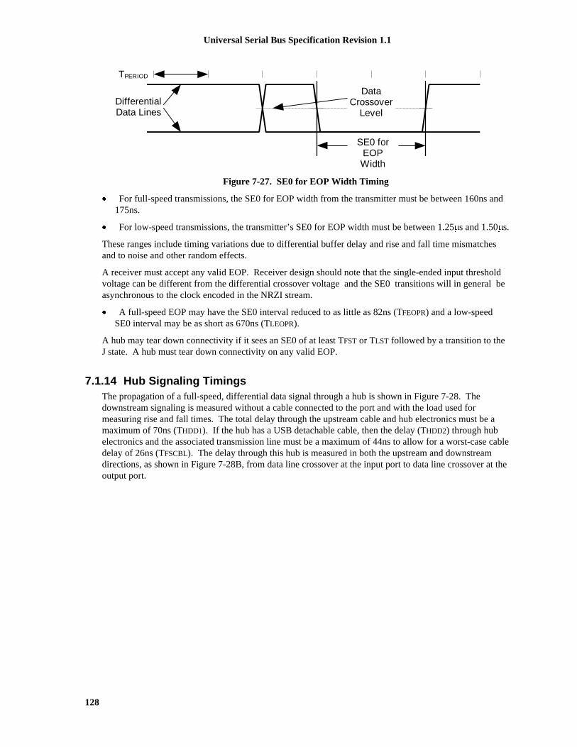
Universal Serial Bus Specification Revision 1.1
128
TPERIOD
DifferentialData Lines
SE0 forEOPWidth
DataCrossover
Level
Figure 7-27. SE0 for EOP Width Timing
� For full-speed transmissions, the SE0 for EOP width from the transmitter must be between 160ns and175ns.
� For low-speed transmissions, the transmitter’s SE0 for EOP width must be between 1.25�s and 1.50�s.
These ranges include timing variations due to differential buffer delay and rise and fall time mismatchesand to noise and other random effects.
A receiver must accept any valid EOP. Receiver design should note that the single-ended input thresholdvoltage can be different from the differential crossover voltage and the SE0 transitions will in general beasynchronous to the clock encoded in the NRZI stream.
� A full-speed EOP may have the SE0 interval reduced to as little as 82ns (TFEOPR) and a low-speedSE0 interval may be as short as 670ns (TLEOPR).
A hub may tear down connectivity if it sees an SE0 of at least TFST or TLST followed by a transition to theJ state. A hub must tear down connectivity on any valid EOP.
7.1.14 Hub Signaling TimingsThe propagation of a full-speed, differential data signal through a hub is shown in Figure 7-28. Thedownstream signaling is measured without a cable connected to the port and with the load used formeasuring rise and fall times. The total delay through the upstream cable and hub electronics must be amaximum of 70ns (THDD1). If the hub has a USB detachable cable, then the delay (THDD2) through hubelectronics and the associated transmission line must be a maximum of 44ns to allow for a worst-case cabledelay of 26ns (TFSCBL). The delay through this hub is measured in both the upstream and downstreamdirections, as shown in Figure 7-28B, from data line crossover at the input port to data line crossover at theoutput port.

Universal Serial Bus Specification Revision 1.1
129
50% Point ofInitial Swing
VSS
Upstream Endof Cable
Upstream Endof Cable
VSS
B. Upstream Hub DelayA. Downstream Hub Delay
DownstreamPort
Data LineCrossover
Point
Hub DelayUpstream70ns (max)
Data LineCrossover
PointDownstream
Port50% Point ofInitial Swing
Hub DelayDownstream
70ns (max)
upstream end of cable
Host orHub
Function
upstream port downstream port
Hub
upstream signaling
downstream signaling
plug receptacle
C. Measurement Points
Figure 7-28. Hub Propagation Delay of Full-speed Differential Signals
Low-speed propagation delay for differential signals is measured in the same fashion as for full-speedsignaling. The maximum low-speed hub delay is 300ns (TLHDD). This allows for the slower low-speedbuffer propagation delay and rise and fall times. It also provides time for the hub to re-clock the low-speeddata in the upstream direction.
When the hub acts as a repeater, it must reproduce the received, full-speed signal accurately on its outputs.This means that for differential signals, the propagation delays of a J-to-K state transition must matchclosely to the delays of a K-to-J state transition. For full-speed propagation, the maximum differenceallowed between these two delays (THDJ1) (see Figure 7-28 and Figure 7-42) for a hub plus cable is �3.0ns.Similarly, the difference in delay between any two J-to-K or K-to-J transitions through a hub (THDJ2) mustbe less than �1.0ns. For low-speed propagation in the downstream direction, the corresponding allowablejitter (TLDHJ1) is �45ns and (TLDHJ2) �15ns, respectively. For low-speed propagation in the upstreamdirection, the allowable jitter is �45ns in both cases (TLUHJ1 and TLUHJ2).
An exception to this case is the skew that can be introduced in the Idle-to-K state transition at SOP (TFSOP
and TLSOP) (refer to Section 7.1.7.2). In this case, the delay to the opposite port includes the time to enablethe output buffer. However, the delays should be closely matched to the normal hub delay and themaximum additional delay difference over a normal J-to-K transition is �5.0ns. This limits the maximumdistortion of the first bit in the packet.
Note: because of this distortion of the SOP transition relative to the next K-to-J state transition, the firstSYNC field bit should not be used to synchronize the receiver to the data stream.
The EOP must be propagated through a hub in the same way as the differential signaling. The propagationdelay for sensing an SE0 must be no less than the greater of the J-to-K, or K-to-J differential data delay (toavoid truncating the last data bit in a packet), but not more than 15ns greater than the larger of thesedifferential delays at full-speed and 200ns at low-speed (to prevent creating a bit stuff error at the end ofthe packet). EOP delays are shown in Figure 7-43.
Because the sense levels for the SE0 state are not at the midpoint of the signal swing, the width of SE0state will be changed as it passes through each hub. A hub may not change the width of the SE0 state in a

Universal Serial Bus Specification Revision 1.1
130
full-speed EOP by more than �15ns (TFHESK), as measured by the difference of the leading edge andtrailing edge delays of the SE0 state (see Figure 7-43). An SE0 from a low-speed device has long rise andfall times and is subject to greater skew, but this conditions exists only on the cable from the low-speeddevice to the port to which it is connected. Thereafter, the signaling uses full-speed buffers and their fasterrise and fall times. The SE0 from the low-speed device cannot be changed by more than �300ns (TLHESK)as it passes through the hub to which the device is connected. This time allows for some signalconditioning in the low-speed port to reduce its sensitivity to noise.
7.1.15 Receiver Data JitterThe data receivers for all types of devices must be able to properly decode the differential data in thepresence of jitter. The more of the bit cell that any data edge can occupy and still be decoded, the morereliable the data transfer will be. Data receivers are required to decode differential data transitions thatoccur in a window plus and minus a nominal quarter bit cell from the nominal (centered) data edgeposition. (A simple 4X over-sampling state machine DPLL can be built that satisfies these requirements.)This requirement is derived in Table 7-2 and Table 7-3. The tables assume a worst-case topology of fivehubs between the host and device and the worst-case number of seven bits between transitions. Thederived numbers are rounded up for ease of specification.
Jitter will be caused by the delay mismatches discussed above and by mismatches in the source anddestination data rates (frequencies). The receive data jitter budgets for full- and low-speed are given inTable 7-2 and Table 7-3. These tables give the value and totals for each source of jitter for bothconsecutive (next) and paired transitions. Note that the jitter component related to the source or destinationfrequency tolerance has been allocated to the appropriate device (i.e., the source jitter includes bit shiftsdue to source frequency inaccuracy over the worst-case data transition interval). The output driver jittercan be traded off against the device clock accuracy in a particular implementation as long as the jitterspecification is met.
The low-speed jitter budget table has an additional line in it because the jitter introduced by the hub towhich the low-speed device is attached is different from all the other devices in the data path. Theremaining devices operate with full-speed signaling conventions (though at low-speed data rate).

Universal Serial Bus Specification Revision 1.1
131
Table 7-2. Full-speed Jitter Budget
Jitter Source Full-speed
Next Transition Paired Transition
Each (ns) Total (ns) Each (ns) Total (ns)
Source Driver Jitter 2.0 2.0 1.0 1.0
Source Frequency Tolerance (worst-case) 0.21/bit 1.5 0.21/bit 3.0
Source Jitter Total 3.5 4.0
Hub Jitter 3.0 15.0 1.0 5.0
Jitter Specification 18.5 9.0
Destination Frequency Tolerance 0.21/bit 1.5 0.21/bit 3.0
Receiver Jitter Budget 20.0 12.0
Table 7-3. Low-speed Jitter Budget
Jitter Source Low-speed Upstream
Next Transition Paired Transition
Each (ns) Total (ns) Each (ns) Total (ns)
Function Driver Jitter 25.0 25.0 10.0 10.0
Function Frequency Tolerance (worst-case) 10.0/bit 70.0 10.0/bit 140.0
Source (Function) Jitter Total 95.0 150.0
Hub with Low-speed Device Jitter 45.0 45.0 45.0 45.0
Remaining (full-speed) Hubs' Jitter 3.0 12.0 1.0 4.0
Jitter Specification 152.0 199.0
Host Frequency Tolerance 1.7/bit 12.0 1.7/bit 24.0
Host Receiver Jitter Budget 164.0 223.0
Low-speed Downstream
Next Transition Paired Transition
Each (ns) Total (ns) Each (ns) Total (ns)
Host Driver Jitter 2.0 2.0 1.0 1.0
Host Frequency Tolerance (worst-case) 1.7/bit 12.0 1.7/bit 24.0
Source (Host) Jitter Total 14.0 25.0
Hub with Low-speed Device Jitter 45.0 45.0 15.0 15.0
Remaining (full-speed) Hubs' Jitter 3.0 12.0 1.0 4.0
Jitter Spec 71.0 44.0
Function Frequency Tolerance 10.0/bit 70.0 10.0/bit 140.0
Function Receiver Jitter Budget 141.0 184.0
Note: this table describes the host transmitting at low-speed data rate using full-speed signaling toa low-speed device through the maximum number of hubs. When the host is directly connected tothe low-speed device, then it uses low-speed data rate and low-speed signaling, and the host has tomeet the source jitter listed in the “Jitter Specification” row.

Universal Serial Bus Specification Revision 1.1
132
7.1.16 Cable DelayExcept (in certain cases) for the SOP, only one data transition is allowed on a USB cable at a time. A full-speed signal edge has to propagate to the far end of the cable, return, and settle within one full-speed bittime. Therefore, the maximum total one-way signal propagation delay allowed is 30ns. The allocation forcable delay is 26ns. A maximum delay of 3ns is allowed from a Host or Hub Controller downstream portto its exterior downstream connector, while a maximum delay of 1ns is allowed from the upstreamconnector to the upstream port of any device. For a standard USB detachable cable, the cable delay ismeasured from the Series A connector pins to the Series B connector pins and is no more than 26ns. Forother cables, the delay is measured from the series A connector to the point where the cable is connected tothe device.
The maximum one-way data delay on a full-speed cable is measured as shown in Figure 7-29.
One-way cable delay for low-speed cables must be less than 18ns. It is measured as shown inFigure 7-30.
A-Connector B-Connector
Total One-WayPropagation Delay
30ns (max)
Data LineCrossover
Point at input ofB-connector
50% Point of Initial SwingVSS
VSS
Driver Endof Cable
ReceiverEnd ofCable
One Way CableDelay 26ns
(max)
Host/Hub Hub/Device
DownstreamPort
UpstreamPort
Traces on Board
3ns (max) 1ns (max)
Figure 7-29. Full-speed Cable Delay
A-Connector + cable
18nS (max)
Host/Hub Low-speedDevice
DownstreamPort
Traces on Board
One-way Propagation Delay
Figure 7-30. Low-speed Cable Delay

Universal Serial Bus Specification Revision 1.1
133
7.1.17 Cable AttenuationThe allowable attenuation of the signal pair (D+, D-) for full speed signaling per cable is listed in Table7-4. The cable attenuation measurement is defined in Section 6.7.
Table 7-4. Signal Attenuation
Frequency (MHz) Attenuation (maximum) dB/cable
0.064 0.08
0.256 0.11
0.512 0.13
0.772 0.15
1.000 0.20
4.000 0.39
8.000 0.57
12.000 0.67
24.000 0.95
48.000 1.35
96.000 1.9
7.1.18 Bus Turn-around Time and Inter-packet DelayInter-packet delays are measured from the SE0-to-J transition at the end of the EOP to the J-to-K transitionthat starts the next packet.
A device is required to allow two bit times of inter-packet delay. The delay is measured at the respondingdevice with a bit time defined in terms of the response. This provides adequate time for the device sendingthe EOP to drive J for one bit time and then turn off its output buffers.
The host must provide at least two bit times of J after the SE0 of an EOP and the start of a new packet(TIPD). If a function is expected to provide a response to a host transmission, the maximum inter-packetdelay for a function or hub with a detachable (TRSPIPD1) cable is 6.5 bit times measured at the Series Breceptacle. If the device has a captive cable, the inter-packet delay (TRSPIPD2) must be less than 7.5 bittimes as measured at the Series-A plug. These timings apply to both full-speed and low-speed devices andthe bit times are referenced to the data rate of the packet.
The maximum inter-packet delay for a host response is 7.5 bit times, measured at the host’s port pins.There is no maximum inter-packet delay between packets in unrelated transactions.
7.1.19 Maximum End-to-end Signal DelayA device expecting a response to a transmission will invalidate the transaction if it does not see the start-of-packet (SOP) transition within the timeout period after the end of the transmission (after the SE0-to-J statetransition in the EOP). This can occur between an IN token and the following data packet or between a

Universal Serial Bus Specification Revision 1.1
134
data packet and the handshake packet (refer to Chapter 8). The device expecting the response will not timeout before 16 bit times but will timeout before 18 bit times (measured at the data pins of the device fromthe SE0-to-J transition at the end of the EOP). The host will wait at least 18 bit times for a response to startbefore it will start a new transaction.
Figure 7-31 depicts the configuration of six signal hops (cables) that results in allowable worst-case signaldelay. The maximum propagation delay from the upstream end of a hub’s cable to any downstream portconnector is 70ns.
HostController
Function
Cable Delay + Hub Delay �� 70ns (each)
Hub 5 Hub 4 Hub 3 Hub 2 Hub 1
Propagation Delay �� 30ns
Figure 7-31. Worst-case End to End Signal Delay Model
7.2 Power DistributionThis section describes the USB power distribution specification.
7.2.1 Classes of DevicesThe power source and sink requirements of different device classes can be simplified with the introductionof the concept of a unit load. A unit load is defined to be 100mA. The number of unit loads a device candraw is an absolute maximum, not an average over time. A device may be either low-power at one unitload or high-power, consuming up to five unit loads. All devices default to low-power. The transition tohigh-power is under software control. It is the responsibility of software to ensure adequate power isavailable before allowing devices to consume high-power.
The USB supports a range of power sourcing and power consuming agents; these include the following:
� Root port hubs: Are directly attached to the USB Host Controller. Hub power is derived from thesame source as the Host Controller. Systems that obtain operating power externally, either AC or DCmust supply at least five unit loads to each port. Such ports are called high-power ports. Battery-powered systems may supply either one or five unit loads. Ports that can supply only one unit load aretermed low-power ports.
� Bus-powered hubs: Draw all of their power for any internal functions and downstream ports fromVBUS on the hub’s upstream port. Bus-powered hubs may only draw up to one unit load upon power-up, and five unit loads after configuration. The configuration power is split between allocations to thehub, any non-removable functions and the external ports. External ports in a bus-powered hub cansupply only one unit load per port regardless of the current draw on the other ports of that hub. Thehub must be able to supply this port current when the hub is in the Active or Suspend state.
� Self-powered hubs: Power for the internal functions and downstream ports does not come fromVBUS. However, the USB interface of the hub may draw up to one unit load from its upstream VBUS
to allow the interface to function when the remainder of the hub is powered down. Hubs that obtainoperating power externally (from the USB) must supply five unit loads to each port. Battery-poweredhubs may supply either one or five unit loads per port.
� Low-power bus-powered functions: All power to these devices comes from VBUS. They may drawno more than one unit load at any time.
� High-power bus-powered functions: All power to these devices comes from VBUS. They must drawno more than one unit load upon power-up and may draw up to five unit loads after being configured.

Universal Serial Bus Specification Revision 1.1
135
� Self-powered functions: May draw up to one unit load from VBUS to allow the USB interface tofunction when the remainder of the function is powered down. All other power comes from anexternal (to the USB) source.
No device shall supply (source) current on VBUS at its upstream port at any time. From VBUS on itsupstream port, a device may only draw (sink) current. They may not provide power to the pull-up resistoron D+/D- unless VBUS is present (see Section 7.1.5). On power-up, a device needs to ensure that itsupstream port is not driving the bus, so that the device is able to receive the reset signaling. Devices mustalso ensure that the maximum operating current drawn by a device is one unit load, until configured. Anydevice that draws power from the bus must be able to detect lack of activity on the bus, enter the Suspendstate and reduce its current consumption from VBUS (refer to Section 7.2.3 and Section 9.2.5.1).
7.2.1.1 Bus-powered HubsBus-powered hub power requirements can be met with a power control circuit such as the one shown inFigure 7-32. Bus-powered hubs often contain at least one non-removable function. Power is alwaysavailable to the hub’s controller, which permits host access to power management and other configurationregisters during the enumeration process. A non-removable function(s) may require that its power beswitched, so that upon power-up the entire device (hub and non-removable functions) draws no more thanone unit load. Power switching on any non-removable function may be implemented either by removingits power or by shutting off the clock. Switching on the non-removable function is not required if theaggregate power drawn by it and the Hub Controller is less than one unit load. However, as long as thehub port associated with the function is in the Power-off state, the function must be logically reset and thedevice must appear to be not connected. The total current drawn by a bus-powered device is the sum of thecurrent to the Hub Controller, any non-removable function(s), and the downstream ports.
Figure 7-32 shows the partitioning of power based upon the maximum upstream current draw of five unitloads: one unit load for the Hub Controller and the non-removable function, and one unit load for each ofthe external downstream ports. If more than four external ports are required, then the hub will need to beself-powered. If the non-removable function(s) and Hub Controller draw more than one unit load, then thenumber of external ports must be appropriately reduced. Power control to a bus-powered hub may requirea regulator. If present, the regulator is always enabled to supply the Hub Controller. The regulator canalso power the non-removable functions(s). Inrush current limiting must also be incorporated into theregulator subsystem.
Non-removableFunction
Hub ControllerDownstreamData Ports
Downstream VBUS
Upstream VBUS
UpstreamData Port
On/OffRegulator
Switch
On/Off
1 unit load/port
Iportctrl
1 unit load -Iportctrl
5 unit loads
Figure 7-32. Compound Bus-powered Hub
Power to external downstream ports of a bus-powered hub must be switched. The Hub Controller suppliesa software controlled on/off signal from the host, which is in the “off” state when the device is powered upor after reset signaling. When switched to the “on” state, the switch implements a soft turn-on function that

Universal Serial Bus Specification Revision 1.1
136
prevents excessive transient current from being drawn from the upstream port. The voltage drop across theupstream cable, connectors, and switch in a bus-powered hub must not exceed 350mV at maximum ratedcurrent.
7.2.1.2 Self-powered HubsSelf-powered hubs have a local power supply that furnishes power to any non-removable functions and toall downstream ports, as shown in Figure 7-33. Power for the Hub Controller, however, may be suppliedfrom the upstream VBUS (a “hybrid” powered hub) or the local power supply. The advantage of supplyingthe Hub Controller from the upstream supply is that communication from the host is possible even if thedevice’s power supply remains off. This makes it possible to differentiate between a disconnected and anunpowered device. If the hub draw power for its upstream port from VBUS, it may not draw more than oneunit load.
Non-removableFunction
Hub Controller
DownstreamData Ports
Downstream V BUS
UpstreamData Port
Regulator
Current Limit
Upstream V BUS1 unit load (max)
Local Power Supply
Regulator
On/Off
Current Limit
.
.
.
.
.
.
.
5 unit loads/port
Figure 7-33. Compound Self-powered Hub
The number of ports that can be supported is limited only by the address capability of the hub and thelocal supply.
Self-powered hubs may experience loss of power. This may be the result of disconnecting the power cordor exhausting the battery. Under these conditions, the hub may force a re-enumeration of itself as a bus-powered hub. This requires the hub to implement port power switching on all external ports. When poweris lost, the hub must ensure that upstream current does not exceed low-power. All the rules of a bus-powered hub then apply.
7.2.1.2.1 Over-current ProtectionThe host and all self-powered hubs must implement over-current protection for safety reasons, and the hubmust have a way to detect the over-current condition and report it to the USB software. Should theaggregate current drawn by a gang of downstream ports exceed a preset value, the over-current protectioncircuit removes or reduces power from all affected downstream ports. The over-current condition isreported through the hub to Host Controller, as described in Section 11.13.5. The preset value cannotexceed 5.0 A and must be sufficiently above the maximum allowable port current such that transientcurrents (e.g. during power up or dynamic attach or reconfiguration) do not trip the over-current protector.

Universal Serial Bus Specification Revision 1.1
137
If an over-current condition occurs on any port, subsequent operation of the USB is not guaranteed, andonce the condition is removed, it may be necessary to reinitialize the bus as would be done upon power-up.The over-current limiting mechanism must be resettable without user mechanical intervention. PolymericPTCs and solid-state switches are examples of methods, which can be used for over-current limiting.
7.2.1.3 Low-power Bus-powered FunctionsA low-power function is one that draws up to one unit load from the USB cable when operational. Figure7-34 shows a typical bus-powered, low-power function, such as a mouse. Low-power regulation can beintegrated into the function silicon. Low-power functions must be capable of operating with input VBUS
voltages as low as 4.40V, measured at the plug end of the cable.
Function
Upstream V BUS
UpstreamData Port
Regulator1 unit load (max)
Figure 7-34. Low-power Bus-powered Function
7.2.1.4 High-power Bus-powered FunctionsA function is defined as being high-power if, when fully powered, it draws over one but less than five unitloads from the USB cable. A high-power function requires staged switching of power. It must first comeup in a reduced power state of less than one unit load. At bus enumeration time, its total powerrequirements are obtained and compared against the available power budget. If sufficient power exists, theremainder of the function may be powered on. A typical high-power function is shown in Figure 7-35.The function’s electronics have been partitioned into two sections. The function controller contains theminimum amount of circuitry necessary to permit enumeration and power budgeting. The remainder of thefunction resides in the function block. High-power functions must be capable of operating in their low-power (one unit load) mode with an input voltage as low as 4.40V, so that it may be detected andenumerated even when plugged into a bus-powered hub. They must also be capable of operating at fullpower (up to five unit loads) with a VBUS voltage of 4.75V, measured at the upstream plug end of thecable.
FunctionFunction Controller
Upstream VBUS
UpstreamData Port
On/Off
Regulator
1 unit load(max)
5 unit loads (max)
Figure 7-35. High-power Bus-powered Function
7.2.1.5 Self-powered FunctionsFigure 7-36 shows a typical self-powered function. The function controller is powered either from theupstream bus via a low-power regulator or from the local power supply. The advantage of the formerscheme is that it permits detection and enumeration of a self-powered function whose local power supply isturned off. The maximum upstream power that the function controller can draw is one unit load, and the

Universal Serial Bus Specification Revision 1.1
138
regulator block must implement inrush current limiting. The amount of power that the function block maydraw is limited only by the local power supply. Because the local power supply is not required to powerany downstream bus ports, it does not need to implement current limiting, soft start, or power switching.
FunctionFunction Controller
Upstream V BUS
UpstreamData Port
Regulator1 unit load (max)
Local Power Supply
Regulator
Figure 7-36. Self-powered Function
7.2.2 Voltage Drop BudgetThe voltage drop budget is determined from the following:
� The voltage supplied by high-powered hub ports is 4.75V to 5.25V.
� The voltage supplied by low-powered hub ports is 4.4V to 5.25V.
� Bus-powered hubs can have a maximum drop of 350mV from their cable plug (where they attach to asource of power) to their output port connectors (where they supply power).
� The maximum voltage drop (for detachable cables) between the A-series plug and B-series plug onVBUS is 125mV (VBUSD).
� The maximum voltage drop for all cables between upstream and downstream on GND is 125mV(VGNDD).
� All hubs and functions must be able to provide configuration information with as little as 4.40V at theconnector end of their upstream cables. Only low-power functions need to be operational with thisminimum voltage.
� Functions drawing more than one unit load must operate with a 4.75V minimum input voltage at theconnector end of their upstream cables.
Figure 7-37 shows the minimum allowable voltages in a worst-case topology consisting of a bus-poweredhub driving a bus-powered function.
Host orPowered Hub
Bus-poweredHub
Low-powerFunction
4.735V
0.015V
4.640V
0.110V
4.397V
0.003V
4.378V
0.022V
Referencedto Source
Referencedto Hub
4.500V 4.350V
*Under transient conditions, supply at hub can drop from 4.400V to 4.070V
4.750V
0.000V
*4.400V
0.125V
4.625V
0.000V
4.375V
0.025V
Figure 7-37. Worst-case Voltage Drop Topology (Steady State)

Universal Serial Bus Specification Revision 1.1
139
7.2.3 Power Control During Suspend/ResumeSuspend current is a function of unit load allocation. All USB devices initially default to low-power. Low-power devices or high-power devices operating at low-power are limited to 500�A of suspend current. Ifthe device is configured for high-power and enabled as a remote wakeup source, it may draw up to 2.5mAduring suspend. When computing suspend current, the current from VBUS through the bus pull-up andpull-down resistors must be included. Configured bus-powered hubs may also consume a maximum of2.5mA, with 500�A allocated to each available external port and the remainder available to the hub and itsinternal functions. If a hub is not configured, it is operating as a low-power device and must limit itssuspend current to 500�A.
While in the Suspend state, a device may briefly draw more than the average current. The amplitude of thecurrent spike cannot exceed the device power allocation 100mA (or 500mA). A maximum of 1.0 second isallowed for an averaging interval. The average current cannot exceed the average suspend current limit(ICCSH or ICCSL, see Table 7-5) during any 1.0s interval (TSUSAVG1). The profile of the current spike isrestricted so the transient response of the power supply (which may be an efficient, low-capacity, tricklepower supply) is not overwhelmed. The rising edge of the current spike must be no more than 100mA/�s.Downstream ports must be able to absorb the 500mA peak current spike and meet the voltage drooprequirements defined for inrush current during dynamic attach (see Section 7.2.4.1). Figure 7-38illustrates a typical example profile for an averaging interval. If the supply to the pull-up resistor on D+/D-is derived from VBUS, then the suspend current will never go to zero because the pull-up and pull-downresistors will always draw power.
ICCS(H|L)
Averaging Interval
Edge rate mustnot exceed100mA/�s
ICONFIGURED(max)
Current Spike
time
I 0 mA
Figure 7-38. Typical Suspend Current Averaging Profile
Devices are responsible for handling the bus voltage reduction due to the inductive and resistive effects ofthe cable. When a hub is in the Suspend state, it must still be able to provide the maximum current per port(one unit load of current per port for bus-powered hubs and five unit loads per port for self-powered hubs).This is necessary to support remote wakeup-capable devices that will power-up while the remainder of thesystem is still suspended. Such devices, when enabled to do remote wakeup, must drive resume signalingupstream within 10ms of starting to draw the higher, non-suspend current. Devices not capable of remotewakeup must draw the higher current only when not suspended.
When devices wakeup, either by themselves (remote wakeup) or by seeing resume signaling, they mustlimit the inrush current on VBUS. The target maximum droop in the hub VBUS is 330mV. The device musthave sufficient on-board bypass capacitance or a controlled power-on sequence such that the current drawnfrom the hub does not exceed the maximum current capability of the port at any time while the device iswaking up.
Universal Serial Bus Specification Revision 1.1
140
7.2.4 Dynamic Attach and DetachThe act of plugging or unplugging a hub or function must not affect the functionality of another device onother segments of the network. Unplugging a function will stop the transaction between that function andthe host. However, the hub to which this function was attached will recover from this condition and willalert the host that the port has been disconnected.
7.2.4.1 Inrush Current LimitingWhen a function or hub is plugged into the network, it has a certain amount of on-board capacitancebetween VBUS and ground. In addition, the regulator on the device may supply current to its output bypasscapacitance and to the function as soon as power is applied. Consequently, if no measures are taken toprevent it, there could be a surge of current into the device which might pull the VBUS on the hub below itsminimum operating level. Inrush currents can also occur when a high-power function is switched into itshigh-power mode. This problem must be solved by limiting the inrush current and by providing sufficientcapacitance in each hub to prevent the power supplied to the other ports from going out of tolerance. Anadditional motivation for limiting inrush current is to minimize contact arcing, thereby prolongingconnector contact life.
The maximum droop in the hub VBUS is 330mV, or about 10% of the nominal signal swing from thefunction. In order to meet this requirement, the following conditions must be met:
� The maximum load (CRPB) that can be placed at the downstream end of a cable is 10�F in parallelwith 44�. The 10�F capacitance represents any bypass capacitor directly connected across the VBUS
lines in the function plus any capacitive effects visible through the regulator in the device. The 44�
resistance represents one unit load of current drawn by the device during connect.
� If more bypass capacitance is required in the device, then the device must incorporate some form ofVBUS surge current limiting, such that it matches the characteristics of the above load.
� The hub downstream port VBUS power lines must be bypassed (CHPB) with no less than 120�F of low-ESR capacitance per hub. Standard bypass methods should be used to minimize inductance andresistance between the bypass capacitors and the connectors to reduce droop. The bypass capacitorsthemselves should have a low dissipation factor to allow decoupling at higher frequencies.
The upstream port of a hub is also required to meet the above requirements. Furthermore, a bus-poweredhub must provide additional surge limiting in the form of a soft-start circuit when it enables power to itsdownstream ports.
A high-power bus-powered device that is switching from a lower power configuration to a higher powerconfiguration must not cause droop > 330 mV on the VBUS at its upstream hub . The device can meet thisby ensuring that changes in the capacitive load it presents do not exceed 10�F.
Signal pins are protected from excessive currents during dynamic attach by being recessed in the connectorsuch that the power pins make contact first. This guarantees that the power rails to the downstream deviceare referenced before the signal pins make contact. In addition, the signal lines are in a high-impedancestate during connect, so that no current flows for standard signal levels.
7.2.4.2 Dynamic DetachWhen a device is detached from the network with power flowing in the cable, the inductance of the cablewill cause a large flyback voltage to occur on the open end of the device cable. This flyback voltage is notdestructive. Proper bypass measures on the hub ports will suppress any coupled noise. The frequencyrange of this noise is inversely dependent on the length of the cable, to a maximum of 60MHz for a one-meter cable. This will require some low capacitance, very low inductance bypass capacitors on each hubport connector. The flyback voltage and the noise it creates is also moderated by the bypass capacitance onthe device end of the cable. Also, there must be some minimum capacitance on the device end of the cable

Universal Serial Bus Specification Revision 1.1
141
to ensure that the inductive flyback on the open end of the cable does not cause the voltage on the deviceend to reverse polarity. A minimum of 1.0�F is recommended for bypass across VBUS.
7.3 Physical LayerThe physical layer specifications are described in the following subsections.

Universal Serial Bus Specification Revision 1.1
142
7.3.1 Regulatory RequirementsAll USB devices should be designed to meet the applicable regulatory requirements.
7.3.2 Bus Timing/Electrical CharacteristicsTable 7-5. DC Electrical Characteristics
Parameter Symbol Conditions Min. Max. Units
Supply Voltage:
High-power Port VBUS Note 2, Section 7.2.1 4.75 5.25 V
Low-power Port VBUS Note 2, Section 7.2.1 4.40 5.25 V
Supply Current:
High-power Hub Port (out) ICCPRT Section 7.2.1 500 mA
Low-power Hub Port (out) ICCUPT Section 7.2.1 100 mA
High-power Function (in) ICCHPF Section 7.2.1 500 mA
Low-power Function (in) ICCLPF Section 7.2.1 100 mA
Unconfigured Function/Hub (in) ICCINIT Section 7.2.1.4 100 mA
Suspended High-power Device ICCSH Section 7.2.3 ; Note 15 2.5 mA
Suspended Low-power Device ICCSL Section 7.2.3 500 �A
Input Levels:
High (driven) VIH Note 4, Section 7.1.4 2.0 V
High (floating) VIHZ Note 4, Section 7.1.4 2.7 3.6 V
Low VIL Note 4, Section 7.1.4 0.8 V
Differential Input Sensitivity VDI |(D+)-(D-)|;Figure 7-9; Note 4
0.2 V
Differential Common ModeRange
VCM Includes VDI range;Figure 7-9; Note 4
0.8 2.5 V
Output Levels:
Low VOL Note 4, 5, Section 7.1.1 0.0 0.3 V
High (Driven) VOH Note 4, 6, Section 7.1.1 2.8 3.6 V
Output Signal CrossoverVoltage
VCRS Measured as in Figure7-6; Note 10
1.3 2.0 V
Decoupling Capacitance:
Downstream Port BypassCapacitance (per hub)
CHPB VBUS to GND, Section7.2.4.1
120 �F
Upstream Port BypassCapacitance
CRPB VBUS to GND; Note 9,Section 7.2.4.1
1.0 10.0 �F

Universal Serial Bus Specification Revision 1.1
143
Table 7-5. DC Electrical Characteristics (Continued)
Parameter Symbol Conditions Min. Max. Units
Input Capacitance:
Downstream Port CIND Note 2; Section 7.1.6 150 pF
Upstream Port (w/o cable) CINUB Note 3; Section 7.1.6 100 pF
Transceiver edge rate controlcapacitance
CEDGE Section 7.1.6 75 pF
Terminations:
Bus Pull-up Resistor onUpstream Port
RPU 1.5k� �5%Section 7.1.5
1.425 1.575 k�
Bus Pull-down Resistor onDownstream Port
RPD 15k� �5%Section 7.1.5
14.25 15.75 k�
Input impedance exclusive ofpullup/pulldown
ZINP Section 7.1.6 300 k�
Termination voltage forupstream port pullup (RPU)
VTERM Section 7.1.5 3.0 3.6 V
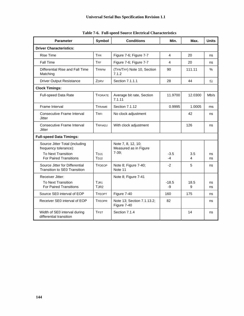
Universal Serial Bus Specification Revision 1.1
144
Table 7-6. Full-speed Source Electrical Characteristics
Parameter Symbol Conditions Min. Max. Units
Driver Characteristics:
Rise Time TFR Figure 7-6; Figure 7-7 4 20 ns
Fall Time TFF Figure 7-6; Figure 7-7 4 20 ns
Differential Rise and Fall TimeMatching
TFRFM (TFR/TFF) Note 10, Section7.1.2
90 111.11 %
Driver Output Resistance ZDRV Section 7.1.1.1 28 44 �
Clock Timings:
Full-speed Data Rate TFDRATE Average bit rate, Section7.1.11
11.9700 12.0300 Mb/s
Frame Interval TFRAME Section 7.1.12 0.9995 1.0005 ms
Consecutive Frame IntervalJitter
TRFI No clock adjustment 42 ns
Consecutive Frame IntervalJitter
TRFIADJ With clock adjustment 126 ns
Full-speed Data Timings:
Source Jitter Total (includingfrequency tolerance):
To Next Transition For Paired Transitions
TDJ1
TDJ2
Note 7, 8, 12, 10;Measured as in Figure7-39; -3.5
-43.54
nsns
Source Jitter for DifferentialTransition to SE0 Transition
TFDEOP Note 8; Figure 7-40;Note 11
-2 5 ns
Receiver Jitter:
To Next Transition For Paired Transitions
TJR1
TJR2
Note 8; Figure 7-41
-18.5-9
18.59
nsns
Source SE0 interval of EOP TFEOPT Figure 7-40 160 175 ns
Receiver SE0 interval of EOP TFEOPR Note 13; Section 7.1.13.2;Figure 7-40
82 ns
Width of SE0 interval duringdifferential transition
TFST Section 7.1.4 14 ns

Universal Serial Bus Specification Revision 1.1
145
Table 7-7. Low-speed Source Electrical Characteristics
Parameter Symbol Conditions Min. Max. Units
Driver Characteristics:
Transition Time:
Rise Time Fall Time
TLR
TLF
Measured as in Figure 7-6 7575
300300
nsns
Rise and Fall Time Matching TLRFM (TLR/TLF) Note 10 80 125 %
Upstream Port(w/cable, low-speed only)
CLINUA Note 1; Section 7.1.6 200 450 pF
Clock Timings:
Low-speed Data Rate TLDRATE Section 7.1.11 1.4775 1.5225 Mb/s
Low-speed Data Timings:
Upstream port source JitterTotal (including frequencytolerance):
To Next Transition For Paired Transitions
TUDJ1
TUDJ2
Note 7, 8; Figure 7-39
-95-150
95150
nsns
Upstream port source Jitter forDifferential Transition to SE0Transition
TLDEOP Note 8; Figure 7-40;Note 11
-40 100 ns
Upstream port differentialReceiver Jitter:
To Next Transition For Paired Transitions
TDJR1
TDJR2
Note 8; Figure 7-41
-75-45
7545
nsns
Downstream port source JitterTotal (including frequencytolerance):
To Next Transition For Paired Transitions
TDDJ1
TDDJ2
Note 7, 8; Figure 7-39
-25-14
2514
nsns
Downstream port source Jitterfor Differential Transition to SE0Transition
Note 8; Figure 7-40;Note 11
ns
Downstream port DifferentialReceiver Jitter:
To Next Transition For Paired Transitions
TUJR1
TUJR2
Note 8; Figure 7-40
-152-200
152200
nsns
Source SE0 interval of EOP TLEOPT Figure 7-40 1.25 1.50 µs
Receiver SE0 interval of EOP TLEOPR Note 13; Section 7.1.13.2;Figure 7-40
670 ns
Width of SE0 interval duringdifferential transition
TLST Section 7.1.4 210 ns

Universal Serial Bus Specification Revision 1.1
146
Table 7-8. Hub/Repeater Electrical Characteristics
Parameter Symbol Conditions Min. Max. Units
Full-speed Hub Characteristics (as measured at connectors):
Driver Characteristics: (Refer to Table 7-6)
Upstream port anddownstream portsconfigured as full-speed
Hub Differential Data Delay:
(with cable) (without cable)
THDD1
THDD2
Note 7, 8
Figure 7-42AFigure 7-42B
7044
nsns
Hub Differential Driver Jitter:(including cable)
To Next Transition For Paired Transitions
THDJ1
THDJ2
Note 7, 8; Figure 7-42,Section 7.1.14
-3-1
31
nsns
Data Bit Width Distortion after SOP TFSOP Note 8; Figure 7-42 -5 5 ns
Hub EOP Delay Relative to THDD TFEOPD Note 8; Figure 7-43 0 15 ns
Hub EOP Output Width Skew TFHESK Note 8; Figure 7-43 -15 15 ns
Low-speed Hub Characteristics (as measured at connectors):
Driver Characteristics: (Refer to Table 7-7)
Downstream portsconfigured as low-speed
Hub Differential Data Delay TLHDD Note 7, 8; Figure 7-42 300 ns
Hub Differential Driver Jitter(including cable):
Downstream port :
To Next Transition For Paired Transitions
Upstream port:
To Next Transition For Paired Transitions
TLDHJ1
TLDHJ2
TLUHJ1
TLUHJ2
Note 7, 8; Figure 7-42
-45-15
-45-45
4515
4545
nsns
nsns
Data Bit Width Distortion after SOP TLSOP Note 8; Figure 7-42 -60 60 ns
Hub EOP Delay Relative to THDD TLEOPD Note 8; Figure 7-43 0 200 ns
Hub EOP Output Width Skew TLHESK Note 8; Figure 7-43 -300 +300 ns

Universal Serial Bus Specification Revision 1.1
147
Table 7-9. Cable Characteristics (Note 14)
Parameter Symbol Conditions Min Max Units
VBUS Voltage drop fordetachable cables
VBUSD Section 7.2.2 125 mV
GND Voltage drop (for allcables)
VGNDD Section 7.2.2 125 mV
Differential Cable Impedance(full-speed)
ZO (90� �15%); 76.5 103.5 �
Cable Delay (one way)
Full-speedLow-speed
TFSCBL
TLSCBL
Section 7.1.16
2618
nsns
Cable Skew TSKEW Section 7.1.3 400 ps
Unmated Contact Capacitance CUC Section 6.7 2 pF
Note 1: Measured at A plug
Note 2: Measured at A receptacle
Note 3: Measured at B receptacle
Note 4: Measured at A or B connector
Note 5: Measured with RL of 1.425k� to 3.6V
Note 6: Measured with RL of 14.25k� to GND
Note 7: Timing difference between the differential data signals
Note 8: Measured at crossover point of differential data signals
Note 9: The maximum load specification is the maximum effective capacitive load allowed that meets the targetVBUS drop of 330mV
Note 10: Excluding the first transition from the Idle state
Note 11: The two transitions should be a (nominal) bit time apart
Note 12: For both transitions of differential signaling
Note 13: Must accept as valid EOP
Note 14: Single-ended capacitance of D+ or D- is the capacitance of D+/D- to all other conductors and, if present,shield in the cable. I.e., to measure the single-ended capacitance of D+, short D-, VBUS, GND and theshield line together and measure the capacitance of D+ to the other conductors.
Note 15: For high power devices (non-hubs) when enabled for remote wakeup
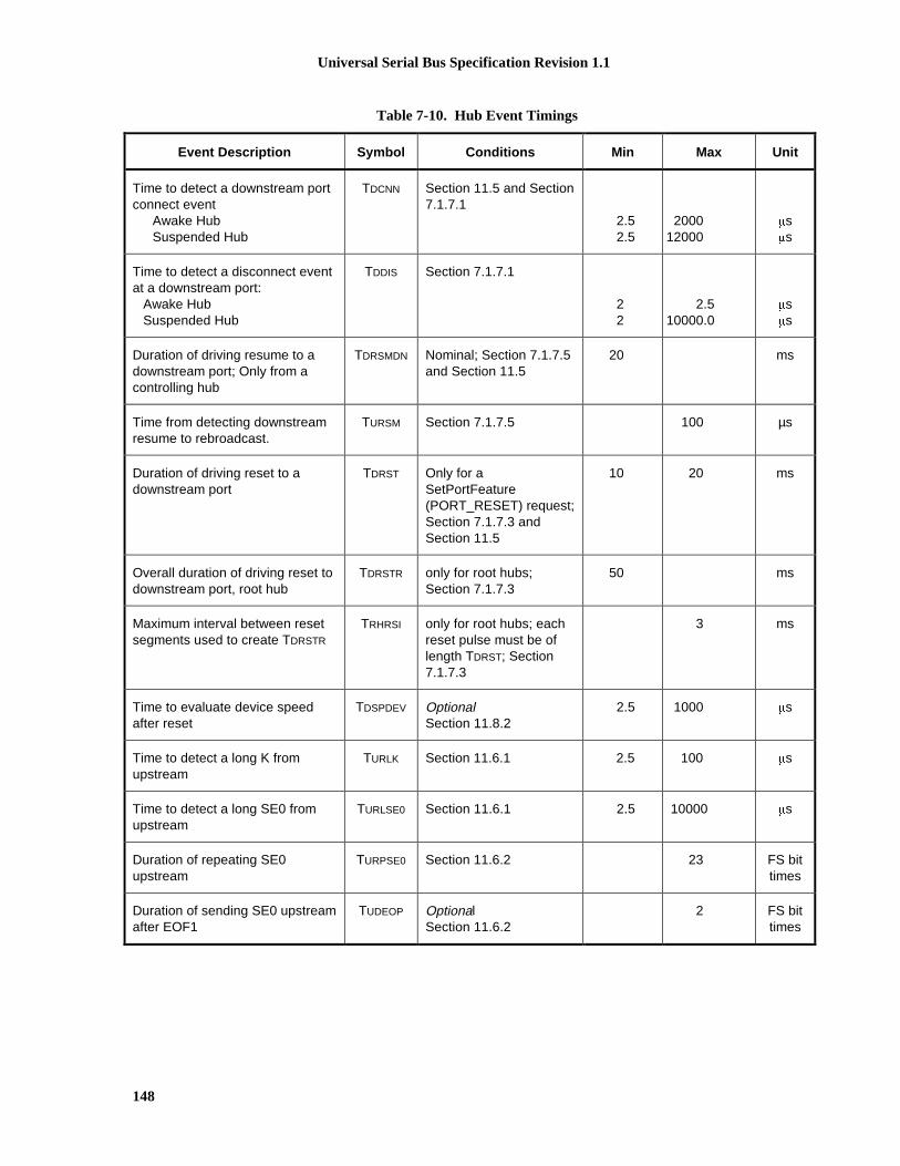
Universal Serial Bus Specification Revision 1.1
148
Table 7-10. Hub Event Timings
Event Description Symbol Conditions Min Max Unit
Time to detect a downstream portconnect event
Awake HubSuspended Hub
TDCNN Section 11.5 and Section7.1.7.1
2.52.5
200012000
�s�s
Time to detect a disconnect eventat a downstream port:
Awake HubSuspended Hub
TDDIS Section 7.1.7.1
22
2.510000.0
�s�s
Duration of driving resume to adownstream port; Only from acontrolling hub
TDRSMDN Nominal; Section 7.1.7.5and Section 11.5
20 ms
Time from detecting downstreamresume to rebroadcast.
TURSM Section 7.1.7.5 100 µs
Duration of driving reset to adownstream port
TDRST Only for aSetPortFeature(PORT_RESET) request;Section 7.1.7.3 andSection 11.5
10 20 ms
Overall duration of driving reset todownstream port, root hub
TDRSTR only for root hubs;Section 7.1.7.3
50 ms
Maximum interval between resetsegments used to create TDRSTR
TRHRSI only for root hubs; eachreset pulse must be oflength TDRST; Section7.1.7.3
3 ms
Time to evaluate device speedafter reset
TDSPDEV OptionalSection 11.8.2
2.5 1000 �s
Time to detect a long K fromupstream
TURLK Section 11.6.1 2.5 100 �s
Time to detect a long SE0 fromupstream
TURLSE0 Section 11.6.1 2.5 10000 �s
Duration of repeating SE0upstream
TURPSE0 Section 11.6.2 23 FS bittimes
Duration of sending SE0 upstreamafter EOF1
TUDEOP OptionalSection 11.6.2
2 FS bittimes

Universal Serial Bus Specification Revision 1.1
149
Table 7-11. Device Event Timings
Parameter Symbol Conditions Min Max Units
Time from internal power good todevice pulling D+/D- beyond VIHZ
(min) (signaling attach)
TSIGATT Figure 7-19 100 ms
Debounce interval provided byUSB system software after attach
TATTDB Figure 7-19 100 ms
Maximum time a device can drawpower >suspend power when busis continuously in idle state
T2SUSP Section 7.1.7.4 10 ms
Maximum duration of suspendaveraging interval
TSUSAVGI Section 7.2.3 1 s
Period of idle bus before devicecan initiate resume
TWTRSM Device must beremote-wakeupenabled. Section7.1.7.5
5 ms
Duration of driving resumeupstream
TDRSMUP Section 7.1.7.5 1 15 ms
Resume Recovery Time TRSMRCY Provided by USBSystem Software;Section 7.1.7.5
10 ms
Time to detect a reset fromupstream
TDETRST Section 7.1.7.3 2.5 10000 �s
Reset Recovery Time TRSTRCY Section 7.1.7.3 10 ms
Inter-packet Delay TIPD Section 7.1.18 2 bittimes
Inter-packet delay for deviceresponse w/detachable cable
TRSPIPD1 Section 7.1.18 6.5 bittimes
Inter-packet delay for deviceresponse w/captive cable
TRSPIPD2 Section 7.1.18 7.5 bittimes
SetAddress() Completion Time TDSETADDR Section 9.2.6.3 50 ms
Time to complete standardrequest with no data
TDRQCMPLTND Section 9.2.6.4 50 ms

Universal Serial Bus Specification Revision 1.1
150
Table 7-11. Device Event Timings (Continued)
Parameter Symbol Conditions Min Max Units
Time to deliver first andsubsequent (except last) data forstandard request
TDRETDATA1 Section 9.2.6.4 500 ms
Time to deliver last data forstandard request
TDRETDATAN Section 9.2.6.4 50 ms

Universal Serial Bus Specification Revision 1.1
151
7.3.3 Timing Waveforms
TPERIOD
DifferentialData Lines
CrossoverPoints
PairedTransitions
N * TPERIOD + TxDJ2
ConsecutiveTransitions
N * TPERIOD + TxDJ1
Figure 7-39. Differential Data Jitter
TPERIOD
DifferentialData Lines
CrossoverPoint
Crossover PointExtended
Source EOP Width: TFEOPT
TLEOPT
Receiver EOP Width: TFEOPR,TLEOPR
Diff. Data-to-SE0 Skew
N * TPERIOD + TxDEOP
Figure 7-40. Differential-to-EOP Transition Skew and EOP Width
DifferentialData Lines
PairedTransitions
N * TPERIOD + TxJR2
TPERIOD
ConsecutiveTransitions
N * TPERIOD + TxJR1
TxJR TxJR1 TxJR2
Figure 7-41. Receiver Jitter Tolerance
TPERIOD is the data rate of the receiver that can have the range as defined in Section 7.1.11

Universal Serial Bus Specification Revision 1.1
152
50% Point ofInitial Swing
VSS
UpstreamEnd ofCable
VSS
Hub Differential Jitter:
THDJ1 = THDDx(J) - THDDx(K) or T HDDx(K) - THDDx(J) Consecutive Transit ions
THDJ2 = THDDx(J) - THDDx(J) or T HDDx(K) - THDDx(K) Paired Transitions
Bit after SOP Width Distortion (s ame as data jitter for SOP and next J transition):
TFSOP = THDDx(next J) - T HDDx(SOP)
Low-speed timings are determined in the s ame way for:
TLHDD, TLDHJ1, TLDJH2, TLUHJ1, TLUJH2, and T LSOP
A. Downstream Hub Delay with Cable
DownstreamPort of hub
Hub DelayDownstream
THDD1
UpstreamPort or End
of Cable
C. Upstream Hub Delay with or without Cable
CrossoverPoint
CrossoverPoint
Hub DelayUpstream
THDD1
THDD2
DownstreamPort of hub
DownstreamPort of hub
B. Downstream Hub Delay without Cable
50% Point ofInitial Swing
CrossoverPoint
Hub DelayDownstream
THDD2
UpstreamPort of hub
VSS
VSS
VSS
VSS
Figure 7-42. Hub Differential Delay, Differential Jitter, and SOP Distortion
Note: Measurement locations referenced in Figure 7-42 and Figure 7-43 are specified in Figure 7-28

Universal Serial Bus Specification Revision 1.1
153
EOP Delay:
TFEOPD = TEOPy - THDDx (TEOPy means that this equation applies to TEOP- and T EOP+)
EOP Skew: TFHESK = TEOP+ - TEOP-
Low-speed timings are determined in the same way for: TLEOPD and T LHESK
50% Point ofInitial Swing
VSS
A. Downstream EOP Delay with Cable
VSS
TEOP+TEOP-
UpstreamEnd ofCable
DownstreamPort of hub
B. Downstream EOP Delay without Cable
TEOP
TEOP-
UpstreamPort of hub
DownstreamPort of hub
CrossoverPoint
Extended
C. Upstream EOP Delay with or Without Cable
CrossoverPoint
Extended
CrossoverPoint
Extended
DownstreamPort
TEOP- TEOP+
UpstreamPort or
End of Cable
VSS
VSS
VSS
VSS
Figure 7-43. Hub EOP Delay and EOP Skew

Universal Serial Bus Specification Revision 1.1
154

Universal Serial Bus Specification Revision 1.1
155
Chapter 8Protocol Layer
This chapter presents a bottom-up view of the USB protocol, starting with field and packet definitions.This is followed by a description of packet transaction formats for different transaction types. Link layerflow control and transaction level fault recovery are then covered. The chapter finishes with a discussionof retry synchronization, babble, and loss of bus activity recovery.
8.1 Bit OrderingBits are sent out onto the bus least-significant bit (LSb) first, followed by the next LSb, through to themost-significant bit (MSb) last. In the following diagrams, packets are displayed such that both individualbits and fields are represented (in a left to right reading order) as they would move across the bus.
8.2 SYNC FieldAll packets begin with a synchronization (SYNC) field, which is a coded sequence that generates amaximum edge transition density. The SYNC field appears on the bus as IDLE followed by the binarystring “KJKJKJKK,” in its NRZI encoding. It is used by the input circuitry to align incoming data with thelocal clock and is defined to be eight bits in length. SYNC serves only as a synchronization mechanismand is not shown in the following packet diagrams (refer to Section 7.1.10). The last two bits in the SYNCfield are a marker that is used to identify the end of the SYNC field and, by inference, the start of the PID.
8.3 Packet Field FormatsField formats for the token, data, and handshake packets are described in the following section. Packet bitdefinitions are displayed in unencoded data format. The effects of NRZI coding and bit stuffing have beenremoved for the sake of clarity. All packets have distinct Start- and End-of-Packet delimiters. The Start-of-Packet (SOP) delimeter is part of the SYNC field, and the End-of-Packet (EOP) delimiter is described inChapter 7.
8.3.1 Packet Identifier FieldA packet identifier (PID) immediately follows the SYNC field of every USB packet. A PID consists of afour-bit packet type field followed by a four-bit check field as shown in Figure 8-1. The PID indicates thetype of packet and, by inference, the format of the packet and the type of error detection applied to thepacket. The four-bit check field of the PID ensures reliable decoding of the PID so that the remainder ofthe packet is interpreted correctly. The PID check field is generated by performing a one’s complement ofthe packet type field. A PID error exists if the four PID check bits are not complements of their respectivepacket identifier bits.
(MSb)(LSb)
PID2
PID3
PID10
PID PID0
PID1
PID2
PID3
Figure 8-1. PID Format

Universal Serial Bus Specification Revision 1.1
156
The host and all functions must perform a complete decoding of all received PID fields. Any PID receivedwith a failed check field or which decodes to a non-defined value is assumed to be corrupted and it, as wellas the remainder of the packet, is ignored by the packet receiver. If a function receives an otherwise validPID for a transaction type or direction that it does not support, the function must not respond. Forexample, an IN-only endpoint must ignore an OUT token. PID types, codings, and descriptions are listedin Table 8-1.
Table 8-1. PID Types
PID Type PID Name PID[3:0]* Description
Token OUT
IN
SOF
SETUP
0001B
1001B
0101B
1101B
Address + endpoint number in host-to-functiontransaction
Address + endpoint number in function-to-hosttransaction
Start-of-Frame marker and frame number
Address + endpoint number in host-to-functiontransaction for SETUP to a control pipe
Data DATA0
DATA1
0011B
1011B
Data packet PID even
Data packet PID odd
Handshake ACK
NAK
STALL
0010B
1010B
1110B
Receiver accepts error-free data packet
Rx device cannot accept data or Tx device cannot senddata
Endpoint is halted or a control pipe request is notsupported.
Special PRE 1100B Host-issued preamble. Enables downstream bus trafficto low-speed devices.
*Note: PID bits are shown in MSb order. When sent on the USB, the rightmost bit (bit 0) will be sent first.
PIDs are divided into four coding groups: token, data, handshake, and special, with the first twotransmitted PID bits (PID<0:1>) indicating which group. This accounts for the distribution of PID codes.
8.3.2 Address FieldsFunction endpoints are addressed using two fields: the function address field and the endpoint field. Afunction needs to fully decode both address and endpoint fields. Address or endpoint aliasing is notpermitted, and a mismatch on either field must cause the token to be ignored. Accesses to non-initializedendpoints will also cause the token to be ignored.

Universal Serial Bus Specification Revision 1.1
157
8.3.2.1 Address FieldThe function address (ADDR) field specifies the function, via its address, that is either the source ordestination of a data packet, depending on the value of the token PID. As shown in Figure 8-2, a total of128 addresses are specified as ADDR<6:0>. The ADDR field is specified for IN, SETUP, and OUTtokens. By definition, each ADDR value defines a single function. Upon reset and power-up, a function’saddress defaults to a value of zero and must be programmed by the host during the enumeration process.Function address zero is reserved as the default address and may not be assigned to any other use.
(LSb) (MSb)
Addr 4 Addr 5 Addr 6Addr 3Addr 2Addr 1Addr 0
Figure 8-2. ADDR Field
8.3.2.2 Endpoint FieldAn additional four-bit endpoint (ENDP) field, shown in Figure 8-3 permits more flexible addressing offunctions in which more than one endpoint is required. Except for endpoint address zero, endpointnumbers are function-specific. The endpoint field is defined for IN, SETUP, and OUT token PIDs only.All functions must support a control pipe at endpoint number zero (the Default Control Pipe). Low-speeddevices support a maximum of three pipes per function: a control pipe at endpoint number zero plus twoadditional pipes (either two control pipes, a control pipe and a interrupt endpoint, or two interruptendpoints). Full-speed functions may support up to the maximum of 16 endpoint numbers of any type.
Endp 2 Endp 3Endp
1Endp
0
(LSb) (MSb)
Figure 8-3. Endpoint Field
8.3.3 Frame Number FieldThe frame number field is an 11-bit field that is incremented by the host on a per-frame basis. The framenumber field rolls over upon reaching its maximum value of 7FFH, and is sent only in SOF tokens at thestart of each frame.
8.3.4 Data FieldThe data field may range from zero to 1,023 bytes and must be an integral number of bytes. Figure 8-4shows the format for multiple bytes. Data bits within each byte are shifted out LSb first.
(MSb) (LSb)(MSb)(LSb)
Byte N Byte N+1
D0 D5D4D3D2D1 D6 D7 D0D7
Byte N-1
Figure 8-4. Data Field Format
Data packet size varies with the transfer type, as described in Chapter 5.

Universal Serial Bus Specification Revision 1.1
158
8.3.5 Cyclic Redundancy ChecksCyclic redundancy checks (CRCs) are used to protect all non-PID fields in token and data packets. In thiscontext, these fields are considered to be protected fields. The PID is not included in the CRC check of apacket containing a CRC. All CRCs are generated over their respective fields in the transmitter before bitstuffing is performed. Similarly, CRCs are decoded in the receiver after stuffed bits have been removed.Token and data packet CRCs provide 100% coverage for all single- and double-bit errors. A failed CRC isconsidered to indicate that one or more of the protected fields is corrupted and causes the receiver to ignorethose fields, and, in most cases, the entire packet.
For CRC generation and checking, the shift registers in the generator and checker are seeded with an all-ones pattern. For each data bit sent or received, the high order bit of the current remainder is XORed withthe data bit and then the remainder is shifted left one bit and the low-order bit set to zero. If the result ofthat XOR is one, then the remainder is XORed with the generator polynomial.
When the last bit of the checked field is sent, the CRC in the generator is inverted and sent to the checkerMSb first. When the last bit of the CRC is received by the checker and no errors have occurred, theremainder will be equal to the polynomial residual.
A CRC error exists if the computed checksum remainder at the end of a packet reception does not matchthe residual.
Bit stuffing requirements must be met for the CRC, and this includes the need to insert a zero at the end ofa CRC if the preceding six bits were all ones.
8.3.5.1 Token CRCsA five-bit CRC field is provided for tokens and covers the ADDR and ENDP fields of IN, SETUP, andOUT tokens or the time stamp field of an SOF token. The generator polynomial is:
G(X) = X5 + X2 + 1
The binary bit pattern that represents this polynomial is 00101B. If all token bits are received withouterror, the five-bit residual at the receiver will be 01100B.
8.3.5.2 Data CRCsThe data CRC is a 16-bit polynomial applied over the data field of a data packet. The generatingpolynomial is:
G(X) = X16 + X15 + X2 + 1
The binary bit pattern that represents this polynomial is 1000000000000101B. If all data and CRC bits arereceived without error, the 16-bit residual will be 1000000000001101B.
8.4 Packet Formats
This section shows packet formats for token, data, and handshake packets. Fields within a packet aredisplayed in these figures in the order in which bits are shifted out onto the bus.

Universal Serial Bus Specification Revision 1.1
159
8.4.1 Token Packets
Figure 8-5 shows the field formats for a token packet. A token consists of a PID, specifying either IN,OUT, or SETUP packet type; and ADDR and ENDP fields. For OUT and SETUP transactions, the addressand endpoint fields uniquely identify the endpoint that will receive the subsequent Data packet. For INtransactions, these fields uniquely identify which endpoint should transmit a Data packet. Only the hostcan issue token packets. IN PIDs define a Data transaction from a function to the host. OUT and SETUPPIDs define Data transactions from the host to a function.
ADDRPID
8 bits 7 bits
ENDP
4 bits
CRC5
5 bits
Figure 8-5. Token Format
Token packets have a five-bit CRC that covers the address and endpoint fields as shown above. The CRCdoes not cover the PID, which has its own check field. Token and SOF packets are delimited by an EOPafter three bytes of packet field data. If a packet decodes as an otherwise valid token or SOF but does notterminate with an EOP after three bytes, it must be considered invalid and ignored by the receiver.
8.4.2 Start-of-Frame PacketsStart-of-Frame (SOF) packets are issued by the host at a nominal rate of once every 1.00ms �0.0005ms.SOF packets consist of a PID indicating packet type followed by an 11-bit frame number field as illustratedin Figure 8-6.
Frame NumberPID
8 bits 11 bits
CRC5
5 bits
Figure 8-6. SOF Packet
The SOF token comprises the token-only transaction that distributes an SOF marker and accompanyingframe number at precisely timed intervals corresponding to the start of each frame. All full-speedfunctions, including hubs, receive the SOF packet. The SOF token does not cause any receiving functionto generate a return packet; therefore, SOF delivery to any given function cannot be guaranteed. The SOFpacket delivers two pieces of timing information. A function is informed that an SOF has occurred when itdetects the SOF PID. Frame timing sensitive functions, which do not need to keep track of frame number(e.g., a hub), need only decode the SOF PID; they can ignore the frame number and its CRC. If a functionneeds to track frame number, it must comprehend both the PID and the time stamp. Full-speed devices thathave no particular need for bus timing information may ignore the SOF packet.

Universal Serial Bus Specification Revision 1.1
160
8.4.3 Data Packets
A data packet consists of a PID, a data field containing zero or more bytes of data, and a CRC as shown inFigure 8-7. There are two types of data packets, identified by differing PIDs: DATA0 and DATA1. Twodata packet PIDs are defined to support data toggle synchronization (refer to Section 8.6).
PID CRC16
16 bits
DATA
0-1023 bytes8 bits
Figure 8-7. Data Packet Format
Data must always be sent in integral numbers of bytes. The data CRC is computed over only the data fieldin the packet and does not include the PID, which has its own check field.
8.4.4 Handshake Packets
Handshake packets, as shown in Figure 8-8, consist of only a PID. Handshake packets are used to reportthe status of a data transaction and can return values indicating successful reception of data, commandacceptance or rejection, flow control, and halt conditions. Only transaction types that support flow controlcan return handshakes. Handshakes are always returned in the handshake phase of a transaction and maybe returned, instead of data, in the data phase. Handshake packets are delimited by an EOP after one byteof packet field. If a packet decodes as an otherwise valid handshake but does not terminate with an EOPafter one byte, it must be considered invalid and ignored by the receiver.
PID
8 bits
Figure 8-8. Handshake Packet
There are three types of handshake packets:
� ACK indicates that the data packet was received without bit stuff or CRC errors over the data field and thatthe data PID was received correctly. ACK may be issued either when sequence bits match and the receivercan accept data or when sequence bits mismatch and the sender and receiver must resynchronize to eachother (refer to Section 8.6 for details). An ACK handshake is applicable only in transactions in which datahas been transmitted and where a handshake is expected. ACK can be returned by the host for INtransactions and by a function for OUT or SETUP transactions.
� NAK indicates that a function was unable to accept data from the host (OUT) or that a function has no datato transmit to the host (IN). NAK can only be returned by functions in the data phase of IN transactions orthe handshake phase of OUT transactions. The host can never issue NAK. NAK is used for flow controlpurposes to indicate that a function is temporarily unable to transmit or receive data, but will eventually beable to do so without need of host intervention.
� STALL is returned by a function in response to an IN token or after the data phase of an OUT transaction(see Figure 8-9 and Figure 8-13). STALL indicates that a function is unable to transmit or receive data, orthat a control pipe request is not supported. The host is not permitted to return a STALL under anycondition.

Universal Serial Bus Specification Revision 1.1
161
The STALL handshake is used by a device in one of two distinct occasions. The first case, known as“functional stall,” is when the Halt feature associated the endpoint is set. (The Halt feature is specified inChapter 9 of this document.) A special case of the functional stall is the “commanded stall.” Commandedstall occurs when the host explicitly sets the endpoint’s Halt feature, as detailed in Chapter 9. Once afunction’s endpoint is halted, the function must continue returning STALL until the condition causing thehalt has been cleared through host intervention.
The second case, known as “protocol stall,” is detailed in Section 8.5.2. Protocol stall is unique to controlpipes. Protocol stall differs from functional stall in meaning and duration. A protocol STALL is returnedduring the Data or Status stage of a control transfer, and the STALL condition terminates at the beginningof the next control transfer (Setup). The remainder of this section refers to the general case of a functionalstall.
8.4.5 Handshake ResponsesTransmitting and receiving functions must return handshakes based upon an order of precedence detailedin Table 8-2 through Table 8-4. Not all handshakes are allowed, depending on the transaction type andwhether the handshake is being issued by a function or the host. Note that if an error occurs during thetransmission of the token to the function, the function will not respond with any packets until the nexttoken is received and successfully decoded.
8.4.5.1 Function Response to IN TransactionsTable 8-2 shows the possible responses a function may make in response to an IN token. If the function isunable to send data, due to a halt or a flow control condition, it issues a STALL or NAK handshake,respectively. If the function is able to issue data, it does so. If the received token is corrupted, the functionreturns no response.
Table 8-2. Function Responses to IN Transactions
Token ReceivedCorrupted
Function TxEndpoint HaltFeature
Function CanTransmit Data
Action Taken
Yes Don’t care Don’t care Return no response
No Set Don’t care Issue STALL handshake
No Not set No Issue NAK handshake
No Not set Yes Issue data packet
8.4.5.2 Host Response to IN TransactionsTable 8-3 shows the host response to an IN transaction. The host is able to return only one type ofhandshake: ACK. If the host receives a corrupted data packet, it discards the data and issues no response.If the host cannot accept data from a function, (due to problems such as internal buffer overrun) thiscondition is considered to be an error and the host returns no response. If the host is able to accept dataand the data packet is received error-free, the host accepts the data and issues an ACK handshake.

Universal Serial Bus Specification Revision 1.1
162
Table 8-3. Host Responses to IN Transactions
Data PacketCorrupted
Host CanAccept Data
Handshake Returned by Host
Yes N/A Discard data, return no response
No No Discard data, return no response
No Yes Accept data, issue ACK
8.4.5.3 Function Response to an OUT Transaction
Handshake responses for an OUT transaction are shown in Table 8-4. Assuming successful token decode,a function, upon receiving a data packet, may return any one of the three handshake types. If the datapacket was corrupted, the function returns no handshake. If the data packet was received error-free and thefunction’s receiving endpoint is halted, the function returns STALL. If the transaction is maintainingsequence bit synchronization and a mismatch is detected (refer to Section 8.6 for details), then the functionreturns ACK and discards the data. If the function can accept the data and has received the data error-free,it returns ACK. If the function cannot accept the data packet due to flow control reasons, it returns NAK.
Table 8-4. Function Responses to OUT Transactions in Order of Precedence
Data PacketCorrupted
ReceiverHaltFeature
Sequence BitsMatch
Function CanAccept Data
Handshake Returnedby Function
Yes N/A N/A N/A None
No Set N/A N/A STALL
No Not set No N/A ACK
No Not set Yes Yes ACK
No Not set Yes No NAK
8.4.5.4 Function Response to a SETUP Transaction
SETUP defines a special type of host-to-function data transaction that permits the host to initialize anendpoint’s synchronization bits to those of the host. Upon receiving a SETUP token, a function mustaccept the data. A function may not respond to a SETUP token with either STALL or NAK and thereceiving function must accept the data packet that follows the SETUP token. If a non-control endpointreceives a SETUP token, it must ignore the transaction and return no response.
8.5 Transaction Formats
Packet transaction format varies depending on the endpoint type. There are four endpoint types: bulk,control, interrupt, and isochronous.
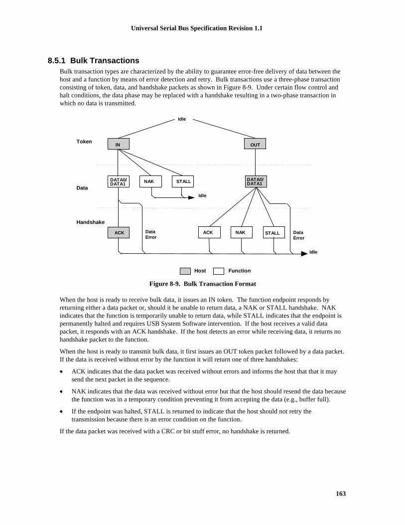
Universal Serial Bus Specification Revision 1.1
163
8.5.1 Bulk TransactionsBulk transaction types are characterized by the ability to guarantee error-free delivery of data between thehost and a function by means of error detection and retry. Bulk transactions use a three-phase transactionconsisting of token, data, and handshake packets as shown in Figure 8-9. Under certain flow control andhalt conditions, the data phase may be replaced with a handshake resulting in a two-phase transaction inwhich no data is transmitted.
Token
Data
FunctionHost
IN OUT
Idle
DATA0/DATA1
ACK
DATA0/DATA1
Idle
ACK
NAK STALL
Idle
STALLNAKDataError
DataError
Handshake
Figure 8-9. Bulk Transaction Format
When the host is ready to receive bulk data, it issues an IN token. The function endpoint responds byreturning either a data packet or, should it be unable to return data, a NAK or STALL handshake. NAKindicates that the function is temporarily unable to return data, while STALL indicates that the endpoint ispermanently halted and requires USB System Software intervention. If the host receives a valid datapacket, it responds with an ACK handshake. If the host detects an error while receiving data, it returns nohandshake packet to the function.
When the host is ready to transmit bulk data, it first issues an OUT token packet followed by a data packet.If the data is received without error by the function it will return one of three handshakes:
� ACK indicates that the data packet was received without errors and informs the host that that it maysend the next packet in the sequence.
� NAK indicates that the data was received without error but that the host should resend the data becausethe function was in a temporary condition preventing it from accepting the data (e.g., buffer full).
� If the endpoint was halted, STALL is returned to indicate that the host should not retry thetransmission because there is an error condition on the function.
If the data packet was received with a CRC or bit stuff error, no handshake is returned.

Universal Serial Bus Specification Revision 1.1
164
Figure 8-10 shows the sequence bit and data PID usage for bulk reads and writes. Data packetsynchronization is achieved via use of the data sequence toggle bits and the DATA0/DATA1 PIDs. A bulkendpoint’s toggle sequence is initialized to DATA0 when the endpoint experiences any configuration event(configuration events are explained in Sections 9.1.1.5 and 9.4.5). Data toggle on an endpoint is NOTinitialized as the direct result of a short packet transfer or the retirement of an IRP.
OUT (0) OUT (0/1)
IN (0) IN (1) IN (0/1)
DATA1
...
...DATA0
DATA0 DATA1
DATA0/1
DATA0/1
OUT (1)BulkWrite
BulkRead
Figure 8-10. Bulk Reads and Writes
The host always initializes the first transaction of a bus transfer to the DATA0 PID with a configurationevent. The second transaction uses a DATA1 PID, and successive data transfers alternate for the remainderof the bulk transfer. The data packet transmitter toggles upon receipt of ACK, and the receiver togglesupon receipt and acceptance of a valid data packet (refer to Section 8.6).
8.5.2 Control TransfersControl transfers minimally have two transaction stages: Setup and Status. A control transfer mayoptionally contain a Data stage between the Setup and Status stages. During the Setup stage, a SETUPtransaction is used to transmit information to the control endpoint of a function. SETUP transactions aresimilar in format to an OUT, but use a SETUP rather than an OUT PID. Figure 8-11 shows the SETUPtransaction format. A SETUP always uses a DATA0 PID for the data field of the SETUP transaction. Thefunction receiving a SETUP must accept the SETUP data and respond with ACK, if the data is corrupted,discard the data and return no handshake.
FunctionHost
Idle
DATA0
ACK
SETUP
Idle
Token
Data
Handshake
Figure 8-11. Control SETUP Transaction
The Data stage, if present, of a control transfer consists of one or more IN or OUT transactions and followsthe same protocol rules as bulk transfers. All the transactions in the Data stage must be in the samedirection (i.e., all INs or all OUTs). The amount of data to be sent during the data phase and its directionare specified during the Setup stage. If the amount of data exceeds the prenegotiated data packet size, the

Universal Serial Bus Specification Revision 1.1
165
data is sent in multiple transactions (INs or OUTs) that carry the maximum packet size. Any remainingdata is sent as a residual in the last transaction.
The Status stage of a control transfer is the last operation in the sequence. A Status stage is delineated by achange in direction of data flow from the previous stage and always uses a DATA1 PID. If, for example,the Data stage consists of OUTs, the status is a single IN transaction. If the control sequence has no Datastage, then it consists of a Setup stage followed by a Status stage consisting of an IN transaction.Figure 8-12 shows the transaction order, the data sequence bit value, and the data PID types for controlread and write sequences. The sequence bits are displayed in parentheses.
SETUP (0) OUT (1) OUT (0/1)
IN (0) IN (0/1)
SetupStage
DataStage
ControlWrite
StatusStage
DATA0 DATA0
...
...DATA1 DATA1
DATA1
IN (1)
OUT (1)
DATA0
DATA0/1
DATA0/1
OUT (0)
IN (1)ControlRead
DATA0 DATA1
SETUP (0)
IN (1)No-dataControl
DATA0 DATA1
SETUP (0)
SetupStage
StatusStage
Figure 8-12. Control Read and Write Sequences
When a STALL handshake is sent by a control endpoint in either the Data or Status stages of a controltransfer, a STALL handshake must be returned on all succeeding accesses to that endpoint until a SETUPPID is received. The endpoint is not required to return a STALL handshake after it receives a subsequentSETUP PID.
8.5.2.1 Reporting Status ResultsThe Status stage reports to the host the outcome of the previous Setup and Data stages of the transfer.Three possible results may be returned:
� The command sequence completed successfully.
� The command sequence failed to complete.
� The function is still busy completing command.
Status reporting is always in the function-to-host direction. The Table 8-5 summarizes the type ofresponses required for each. Control write transfers return status information in the data phase of the Statusstage transaction. Control read transfers return status information in the handshake phase of a Status stagetransaction, after the host has issued a zero-length data packet during the previous data phase.

Universal Serial Bus Specification Revision 1.1
166
Table 8-5. Status Stage Responses
Status Response Control Write Transfer(sent during data phase)
Control Read Transfer(send during handshake phase)
Function completes Zero-length data packet ACK handshake
Function has an error STALL handshake STALL handshake
Function is busy NAK handshake NAK handshake
For control reads, the host sends an OUT token to the control pipe to initiate the Status stage. The hostmay only send a zero-length data packet in this phase but the function may accept any length packet as avalid status inquiry. The pipe’s handshake response to this data packet indicates the current status. NAKindicates that the function is still processing the command and that the host should continue the Statusstage. ACK indicates that the function has completed the command and is ready to accept a newcommand. STALL indicates that the function has an error that prevents it from completing the command.
For control writes, the host sends an IN token to the control pipe to initiate the Status stage. The functionresponds with either a handshake or a zero-length data packet to indicate its current status. NAK indicatesthat the function is still processing the command and that the host should continue the Status stage; returnof a zero-length packet indicates normal completion of the command; and STALL indicates that thefunction cannot complete the command. The function expects the host to respond to the data packet in theStatus stage with ACK. If the function does not receive ACK, it remains in the Status stage of thecommand and will continue to return the zero-length data packet for as long as the host continues to sendIN tokens.
If during a Data stage a command pipe is sent more data or is requested to return more data than wasindicated in the Setup stage (see Section 8.5.2.2), it should return STALL. If a control pipe returns STALLduring the Data stage, there will be no Status stage for that control transfer.
8.5.2.2 Variable-length Data StageA control pipe may have a variable-length data phase in which the host request more data than is containedin the specified data structure. When all of the data structure is returned to the host, the function shouldindicate that the Data stage is ended by returning a packet that is shorter than the MaxPacketSize for thepipe. If the data structure is an exact multiple of wMaxPacketSize for the pipe, the funtion will return azero-length packet to indicate the end of the Data stage.
8.5.2.3 Error Handling on the Last Data TransactionIf the ACK handshake on an IN transaction is corrupted, the function and the host will temporarily disagreeon whether the transaction was successful. If the transaction is followed by another IN, the toggle retrymechanism will detect the mismatch and recover from the error. If the ACK was on the last IN of a Datastage, the toggle retry mechanism cannot be used and an alternative scheme must be used.
The host that successfully received the data of the last IN will send ACK., Later, the host will issue anOUT token to start the Status stage of the transfer. If the function did not receive the ACK that ended theData stage, the function will interpret the start of the Status stage as verification that the host successfullyreceived the data. Control writes do not have this ambiguity. If an ACK handshake on an OUT getscorrupted, the host does not advance to the Status stage and retries the last data instead. A detailed analysisof retry policy is presented in Section 8.6.4.

Universal Serial Bus Specification Revision 1.1
167
8.5.2.4 STALL Handshakes Returned by Control PipesControl pipes have the unique ability to return a STALL handshake due to function problems in controltransfers. If the device is unable to complete a command, it returns a STALL in the Data and/or Statusstages of the control transfer. Unlike the case of a functional stall, protocol stall does not indicate an errorwith the device. The protocol stall condition lasts until the receipt of the next SETUP transaction and thefunction will return STALL in response to any IN or OUT transaction on the pipe until the SETUPtransaction is received. In general, protocol stall indicates that the request or its parameters is notunderstood by the device and thus provides a mechanism for extending USB requests.
A control pipe may also support functional stall as well, but this is not recommended. This is adegenerative case, because a functional stall on a control pipe indicates that it has lost the ability tocommunicate with the host. If the control pipe does support functional stall, then it must possess a Haltfeature, which can be set or cleared by the host. Chapter 9 details how to treat the special case of a Haltfeature on a control pipe. A well-designed device will associate all of its functions and Halt features withnon-control endpoints. The control pipes should be reserved for servicing USB requests.
8.5.3 Interrupt Transactions
Interrupt transactions may consist of IN or OUT transfers. Upon receipt of an IN token, a function mayreturn data, NAK, or STALL. If the endpoint has no new interrupt information to return (i.e., no interruptis pending), the function returns a NAK handshake during the data phase. If the Halt feature is set for theinterrupt endpoint, the function will return a STALL handshake. If an interrupt is pending, the functionreturns the interrupt information as a data packet. The host, in response to receipt of the data packet, issueseither an ACK handshake if data was received error-free or returns no handshake if the data packet wasreceived corrupted. Figure 8-13 shows the interrupt transaction format.
Token
Data
FunctionHost
IN OUT
Idle
DATA0/DATA1
ACK
DATA0/DATA1
Idle
ACK
NAK STALL
Idle
STALLNAKDataError
DataError
Handshake
Figure 8-13. Interrupt Transaction Format
When an endpoint is using the interrupt transfer mechanism for actual interrupt data, the data toggleprotocol must be followed. This allows the function to know that the data has been received by the hostand the event condition may be cleared. This “guaranteed” delivery of events allows the function to onlysend the interrupt information until it has been received by the host rather than having to send the interruptdata every time the function is polled and until the USB System Software clears the interrupt condition.

Universal Serial Bus Specification Revision 1.1
168
When used in the toggle mode, an interrupt endpoint is initialized to the DATA0 PID by any configurationevent on the endpoint and behaves the same as the bulk transactions shown in Figure 8-10.
An interrupt endpoint may also be used to communicate rate feedback information for certain types ofisochronous functions. When used in this mode, the data toggle bits should be changed after each datapacket is sent to the host without regard to the presence or type of handshake packet. This capability issupported only for interrupt IN endpoints.
8.5.4 Isochronous Transactions
Isochronous (ISO) transactions have a token and data phase, but no handshake phase, as shown in Figure8-14. The host issues either an IN or an OUT token followed by the data phase in which the endpoint (forINs) or the host (for OUTs) transmits data. ISO transactions do not support a handshake phase or retrycapability.
See Note Below
Token
Idle
Idle
IN OUT
DATA0 DataDATA0/
FunctionHost
Figure 8-14. Isochronous Transaction Format
Note: a device or Host Controller should be able to accept either DATA0 or DATA1. A device or HostController should only send DATA0.
ISO transactions do not support toggle sequencing.
8.6 Data Toggle Synchronization and Retry
The USB provides a mechanism to guarantee data sequence synchronization between data transmitter andreceiver across multiple transactions. This mechanism provides a means of guaranteeing that thehandshake phase of a transaction was interpreted correctly by both the transmitter and receiver.Synchronization is achieved via use of the DATA0 and DATA1 PIDs and separate data toggle sequencebits for the data transmitter and receiver. Receiver sequence bits toggle only when the receiver is able toaccept data and receives an error-free data packet with the correct data PID. Transmitter sequence bitstoggle only when the data transmitter receives a valid ACK handshake. The data transmitter and receivermust have their sequence bits synchronized at the start of a transaction. The synchronization mechanismused varies with the transaction type. Data toggle synchronization is not supported for ISO transfers.

Universal Serial Bus Specification Revision 1.1
169
8.6.1 Initialization via SETUP TokenControl transfers use the SETUP token for initializing host and function sequence bits. Figure 8-15 showsthe host issuing a SETUP packet to a function followed by an OUT transaction. The numbers in the circlesrepresent the transmitter and receiver sequence bits. The function must accept the data and return ACK.When the function accepts the transaction, it must set its sequence bit so that both the host’s and function’ssequence bits are equal to one at the end of the SETUP transaction.
Tx(1)
Rx(X->1)
Tx(1)
Rx(1)
Rx(X)
SETUP
DATA0
ACK
Acceptdata
Host Device
Tx(X-1)
Figure 8-15. SETUP Initialization
8.6.2 Successful Data TransactionsFigure 8-16 shows the case where two successful transactions have occurred. For the data transmitter, thismeans that it toggles its sequence bit upon receipt of ACK. The receiver toggles its sequence bit only if itreceives a valid data packet and the packet’s data PID matches the current value of its sequence bit. Thetransmitter only toggles its sequence bit after it receives and ACK to a data packet.
During each transaction, the receiver compares the transmitter sequence bit (encoded in the data packetPID as either DATA0 or DATA1) with its receiver sequence bit. If data cannot be accepted, the receivermust issue NAK and the sequence bits of both the transmitter and receiver remain unchanged. If data canbe accepted and the receiver’s sequence bit matches the PID sequence bit, then data is accepted and thesequence bit is toggled. Two-phase transactions in which there is no data packet leave the transmitter andreceiver sequence bits unchanged.
Tx(0)
Rx(0->1)
Tx(0->1)
Rx(1)
DATA0
ACK
Tx(1)
Rx(1->0)
Tx(1->0)
Rx(0)
DATA1
ACK
Transfer i Transfer i + 1
Accept data
Acceptdata
Figure 8-16. Consecutive Transactions
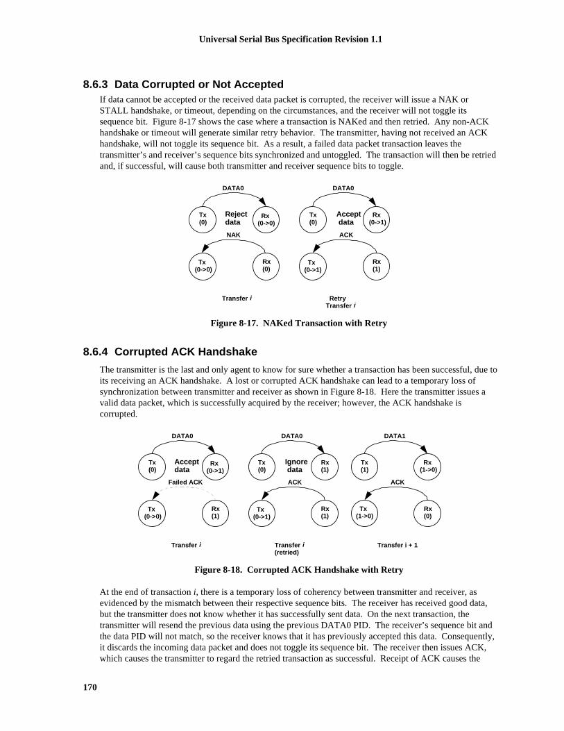
Universal Serial Bus Specification Revision 1.1
170
8.6.3 Data Corrupted or Not AcceptedIf data cannot be accepted or the received data packet is corrupted, the receiver will issue a NAK orSTALL handshake, or timeout, depending on the circumstances, and the receiver will not toggle itssequence bit. Figure 8-17 shows the case where a transaction is NAKed and then retried. Any non-ACKhandshake or timeout will generate similar retry behavior. The transmitter, having not received an ACKhandshake, will not toggle its sequence bit. As a result, a failed data packet transaction leaves thetransmitter’s and receiver’s sequence bits synchronized and untoggled. The transaction will then be retriedand, if successful, will cause both transmitter and receiver sequence bits to toggle.
Tx(0)
Rx(0->0)
Tx(0->0)
Rx(0)
DATA0
NAK
Tx(0)
Rx(0->1)
Tx(0->1)
Rx(1)
DATA0
ACK
Transfer i RetryTransfer i
Accept data
Rejectdata
Figure 8-17. NAKed Transaction with Retry
8.6.4 Corrupted ACK Handshake
The transmitter is the last and only agent to know for sure whether a transaction has been successful, due toits receiving an ACK handshake. A lost or corrupted ACK handshake can lead to a temporary loss ofsynchronization between transmitter and receiver as shown in Figure 8-18. Here the transmitter issues avalid data packet, which is successfully acquired by the receiver; however, the ACK handshake iscorrupted.
Tx(0)
Rx(0->1)
Tx(0->0)
Rx(1)
DATA0
Failed ACK
Tx(0)
Rx(1)
Tx(0->1)
Rx(1)
DATA0
ACK
Transfer i Transfer i(retried)
Tx(1)
Rx(1->0)
Tx(1->0)
Rx(0)
DATA1
ACK
Transfer i + 1
Ignore data
Acceptdata
Figure 8-18. Corrupted ACK Handshake with Retry
At the end of transaction i, there is a temporary loss of coherency between transmitter and receiver, asevidenced by the mismatch between their respective sequence bits. The receiver has received good data,but the transmitter does not know whether it has successfully sent data. On the next transaction, thetransmitter will resend the previous data using the previous DATA0 PID. The receiver’s sequence bit andthe data PID will not match, so the receiver knows that it has previously accepted this data. Consequently,it discards the incoming data packet and does not toggle its sequence bit. The receiver then issues ACK,which causes the transmitter to regard the retried transaction as successful. Receipt of ACK causes the

Universal Serial Bus Specification Revision 1.1
171
transmitter to toggle its sequence bit. At the beginning of transaction i+1, the sequence bits have toggledand are again synchronized.
The data transmitter must guarantee that any retried data packet is identical (same length and content) asthat sent in the original transaction. If the data transmitter is unable, because of problems such as a bufferunderrun condition, to transmit the identical amount of data as was in the original data packet, it must abortthe transaction by generating a bit stuffing violation. This causes a detectable error at the receiver andguarantees that a partial packet will not be interpreted as a good packet. The transmitter should not try toforce an error at the receiver by sending a known bad CRC. A combination of a bad packet with a “bad”CRC may be interpreted by the receiver as a good packet.
8.6.5 Low-speed Transactions
The USB supports signaling at two speeds: full-speed signaling at 12.0Mb/s and low-speed signaling at1.5Mb/s. Hubs disable downstream bus traffic to all ports to which low-speed devices are attached duringfull-speed downstream signaling. This is required both for EMI reasons and to prevent any possibility thata low-speed device might misinterpret downstream a full-speed packet as being addressed to it.Figure 8-19 shows an IN low-speed transaction in which the host issues a token and handshake andreceives a data packet.
SYNC PID SYNC PID
Token sent at low-speed
. . .ENDP EOP
Hub disables low-speed port outputs
SYNC PID SYNC PID
Preamblesent at full-speed
Handshake sent at low-speed
EOP
Data packet sent at low-speed
SYNC PID CRC EOPDATA
Hub disables low-speed port outputs
Hub enables low-speed port outputs
Hub enables low-speed port outputs
Hub setup
Hub setup
Preamblesent at full-speed
Figure 8-19. Low-speed Transaction
All downstream packets transmitted to low-speed devices require a preamble. The preamble consists of aSYNC followed by a PRE PID, both sent at full-speed. Hubs must comprehend the PRE PID; all otherUSB devices may ignore it and treat it as undefined. After the end of the preamble PID, the host must waitat least four full-speed bit times during which hubs must complete the process of enabling the repeaterfunction on ports that are connected to low-speed devices. During this hub setup interval, hubs must drivetheir full-speed and low-speed ports to their respective Idle states. Hubs must be ready to repeat low-speedsignaling on low-speed ports before the end of the hub setup interval. Low-speed connectivity rules aresummarized below:
1. Low-speed devices are identified during the connection process and the hub ports to which they areconnected are identified as low-speed.
2. All downstream low-speed packets must be prefaced with a preamble (sent at full-speed), which turnson the output buffers on low-speed hub ports.

Universal Serial Bus Specification Revision 1.1
172
3. Low-speed hub port output buffers are turned off upon receipt of EOP and are not turned on againuntil a preamble PID is detected.
4. Upstream connectivity is not affected by whether a hub port is full- or low-speed.
Low-speed signaling begins with the host issuing SYNC at low-speed, followed by the remainder of thepacket. The end of the packet is identified by an End-of-Packet (EOP), at which time all hubs tear downconnectivity and disable any ports to which low-speed devices are connected. Hubs do not switch ports forupstream signaling; low-speed ports remain enabled in the upstream direction for both low-speed and full-speed signaling.
Low-speed and full-speed transactions maintain a high degree of protocol commonality. However, low-speed signaling does have certain limitations which include:
� Data payload is limited to eight bytes, maximum
� Only interrupt and control types of transfers are supported
� The SOF packet is not received by low-speed devices.
8.7 Error Detection and RecoveryThe USB permits reliable end-to-end communication in the presence of errors on the physical signalinglayer. This includes the ability to reliably detect the vast majority of possible errors and to recover fromerrors on a transaction-type basis. Control transactions, for example, require a high degree of datareliability; they support end-to-end data integrity using error detection and retry. Isochronous transactions,by virtue of their bandwidth and latency requirements, do not permit retries and must tolerate a higherincidence of uncorrected errors.
8.7.1 Packet Error CategoriesThe USB employs three error detection mechanisms: bit stuff violations, PID check bits, and CRCs. Bitstuff violations are defined in Section 7.1.9. PID errors are defined in Section 8.3.1. CRC errors aredefined in Section 8.3.5.
With the exception of the SOF token, any packet that is received corrupted causes the receiver to ignore itand discard any data or other field information that came with the packet. Table 8-6 lists error detectionmechanisms, the types of packets to which they apply, and the appropriate packet receiver response.
Table 8-6. Packet Error Types
Field Error Action
PID PID Check, Bit Stuff Ignore packet
Address Bit Stuff, Address CRC Ignore token
Frame Number Bit Stuff, Frame Number CRC Ignore Frame Number field
Data Bit Stuff, Data CRC Discard data
8.7.2 Bus Turn-around TimingNeither the device nor the host will send an indication that a received packet had an error. This absence ofpositive acknowledgement is considered to be the indication that there was an error. As a consequence ofthis method of error reporting, the host and USB function need to keep track of how much time has elapsedfrom when the transmitter completes sending a packet until it begins to receive a response. This time is

Universal Serial Bus Specification Revision 1.1
173
referred to as the bus turn-around time. The timer starts counting on the SE0-to-‘J’ transition of the EOPstrobe and stops counting when the Idle-to-‘K’ SOP transition is detected. Both devices and the hostrequire turn-around timers. The device bus turn-around time is defined by the worst case round trip delayplus the maximum device response delay (refer to Section 7.1.18). If a response is not received within thisworst case timeout, then the transmitter considers that the packet transmission has failed. USB devicestimeout no sooner than 16 bit times and no latter than 18 bit times after the end of the previous EOP. If thehost wishes to indicate an error condition via a timeout, it must wait at least 18 bit times before issuing thenext token to ensure that all downstream devices have timed out.
As shown in Figure 8-20, the device uses its bus turn-around timer between token and data or data andhandshake phases. The host uses its timer between data and handshake or token and data phases.
If the host receives a corrupted data packet, it must wait before sending out the next token. This waitinterval guarantees that the host does not attempt to issue a token immediately after a false EOP.
OUT/SETUP
IN
Data
Data
Handshake
Handshake
device waits
device waitshost waits
host waits
Figure 8-20. Bus Turn-around Timer Usage
8.7.3 False EOPsFalse EOPs must be handled in a manner which guarantees that the packet currently in progress completesbefore the host or any other device attempts to transmit a new packet. If such an event were to occur, itwould constitute a bus collision and have the ability to corrupt up to two consecutive transactions.Detection of false EOP relies upon the fact that a packet into which a false EOP has been inserted willappear as a truncated packet with a CRC failure. (The last 16 bits of the packet will have a very lowprobability of appearing to be a correct CRC.)
The host and devices handle false EOP situations differently. When a device sees a corrupted data packet,it issues no response and waits for the host to send the next token. This scheme guarantees that the devicewill not attempt to return a handshake while the host may still be transmitting a data packet. If a false EOPhas occurred, the host data packet will eventually end, and the device will be able to detect the next token.If a device issues a data packet that gets corrupted with a false EOP, the host will ignore the packet and notissue the handshake. The device, expecting to see a handshake from the host, will timeout.
If the host receives a corrupted data packet, it assumes that a false EOP may have occurred and waits for 16bit times to see if there is any subsequent upstream traffic. If no bus transitions are detected within the 16bit interval and the bus remains in the Idle state, the host may issue the next token. Otherwise, the hostwaits for the device to finish sending the remainder of its packet. Waiting 16 bit times guarantees twoconditions:
� The first condition is to make sure that the device has finished sending its packet. This is guaranteedby a timeout interval (with no bus transitions) greater than the worst case six-bit time bit stuff interval.
� The second condition is that the transmitting device’s bus turn-around timer must be guaranteed toexpire.
Note that the timeout interval is transaction speed sensitive. For full-speed transactions, the host must wait16 full-speed bit times; for low-speed transactions, it must wait 16 low-speed bit times.
Universal Serial Bus Specification Revision 1.1
174
If the host receives a data packet with a valid CRC, it assumes that the packet is complete and need notdelay in issuing the next token.
8.7.4 Babble and Loss of Activity RecoveryThe USB must be able to detect and recover from conditions which leave it waiting indefinitely for an EOPor which leave the bus in something other than the Idle state at the end of a frame.
� Loss of activity (LOA) is characterized by SOP followed by lack of bus activity (bus remains driven toa ‘J’ or ‘K’) and no EOP at the end of a frame.
� Babble is characterized by an SOP followed by the presence of bus activity past the end of a frame.
LOA and babble have the potential to either deadlock the bus or force out the beginning of the next frame.Neither condition is acceptable, and both must be prevented from occurring. As the USB componentresponsible for controlling connectivity, hubs are responsible for babble/LOA detection and recovery. AllUSB devices that fail to complete their transmission at the end of a frame are prevented from transmittingpast a frame’s end by having the nearest hub disable the port to which the offending device is attached.Details of the hub babble/LOA recovery mechanism appear in Section 11.8.1.

Universal Serial Bus Specification Revision 1.1
175
Chapter 9USB Device Framework
A USB device may be divided into three layers:
� The bottom layer is a bus interface that transmits and receives packets.
� The middle layer handles routing data between the bus interface and various endpoints on the device.An endpoint is the ultimate consumer or provider of data. It may be thought of as a source or sink fordata.
� The top layer is the functionality provided by the serial bus device; for instance, a mouse or ISDNinterface.
This chapter describes the common attributes and operations of the middle layer of a USB device. Theseattributes and operations are used by the function-specific portions of the device to communicate throughthe bus interface and ultimately with the host.
9.1 USB Device StatesA USB device has several possible states. Some of these states are visible to the USB and the host, whileothers are internal to the USB device. This section describes those states.
9.1.1 Visible Device StatesThis section describes USB device states that are externally visible (see Figure 9-1). Table 9-1 summarizesthe visible device states.
Note: USB devices perform a reset operation in response to reset signaling on the upstream port. Whenreset signaling has completed, the USB device is reset.

Universal Serial Bus Specification Revision 1.1
176
Powered
Defaul t
HubConf igured
Address
Conf igured
DeviceConf igured
DeviceDeconf igured
Suspended
BusInact ive
Bus Activi ty
Bus Activi ty
At tached
Hub Resetor
Deconf igured
Reset
Suspended
Suspended
BusInact ive
BusInact ive
Bus Activi ty
AddressAss igned
Reset
Suspended
Bus Activi ty
BusInact ive
PowerInterruption
Figure 9-1. Device State Diagram

Universal Serial Bus Specification Revision 1.1
177
Table 9-1. Visible Device States
Attached Powered Default Address Configured Suspended State
No -- -- -- -- -- Device is not attached tothe USB. Other attributesare not significant.
Yes No -- -- -- -- Device is attached to theUSB, but is not powered.Other attributes are notsignificant.
Yes Yes No -- -- -- Device is attached to theUSB and powered, buthas not been reset.
Yes Yes Yes No -- -- Device is attached to theUSB and powered andhas been reset, but hasnot been assigned aunique address. Deviceresponds at the defaultaddress.
Yes Yes Yes Yes No -- Device is attached to theUSB, powered, has beenreset, and a uniquedevice address has beenassigned. Device is notconfigured.
Yes Yes Yes Yes Yes No Device is attached to theUSB, powered, has beenreset, has a uniqueaddress, is configured,and is not suspended.The host may now usethe function provided bythe device.
Yes Yes -- -- -- Yes Device is, at minimum,attached to the USB andis powered and has notseen bus activity for 3 ms.It may also have a uniqueaddress and beconfigured for use.However, because thedevice is suspended, thehost may not use thedevice’s function.

Universal Serial Bus Specification Revision 1.1
178
9.1.1.1 AttachedA USB device may be attached or detached from the USB. The state of a USB device when it is detachedfrom the USB is not defined by this specification. This specification only addresses required operationsand attributes once the device is attached.
9.1.1.2 PoweredUSB devices may obtain power from an external source and/or from the USB through the hub to whichthey are attached. Externally powered USB devices are termed self-powered. Although self-powereddevices may already be powered before they are attached to the USB, they are not considered to be in thePowered state until they are attached to the USB and VBUS is applied to the device.
A device may support both self-powered and bus-powered configurations. Some device configurationssupport either power source. Other device configurations may be available only if the device is self-powered. Devices report their power source capability through the configuration descriptor. The currentpower source is reported as part of a device’s status. Devices may change their power source at any time;e.g., from self- to bus-powered. If a configuration is capable of supporting both power modes, the powermaximum reported for that configuration is the maximum the device will draw from VBUS in either mode.The device must observe this maximum, regardless of its mode. If a configuration supports only onepower mode and the power source of the device changes, the device will lose its current configuration andaddress and return to the Powered state. If a device is self-powered and its current configuration requiresmore than 100mA, then if the device switches to being bus-powered, it must return to the Address state.Self-powered hubs that use VBUS to power the Hub Controller are allowed to remain in the Configuredstate if local power is lost. Refer to Section 11.14 for details.
A hub port must be powered in order to detect port status changes, including attach and detach. Bus-powered hubs do not provide any downstream power until they are configured, at which point they willprovide power as allowed by their configuration and power source. A USB device must be able to beaddressed within a specified time period from when power is initially applied (refer to Chapter 7). After anattachment to a port has been detected, the host may enable the port, which will also reset the deviceattached to the port.
9.1.1.3 DefaultAfter the device has been powered, it must not respond to any bus transactions until it has received a resetfrom the bus. After receiving a reset, the device is then addressable at the default address.
9.1.1.4 AddressAll USB devices use the default address when initially powered or after the device has been reset. EachUSB device is assigned a unique address by the host after attachment or after reset. A USB devicemaintains its assigned address while suspended.
A USB device responds to requests on its default pipe whether the device is currently assigned a uniqueaddress or is using the default address.
9.1.1.5 ConfiguredBefore a USB device’s function may be used, the device must be configured. From the device’sperspective, configuration involves writing a non-zero value to the device configuration register.Configuring a device or changing an alternate setting causes all of the status and configuration valuesassociated with endpoints in the affected interfaces to be set to their default values. This includes settingthe data toggle of any endpoint using data toggles to the value DATA0.

Universal Serial Bus Specification Revision 1.1
179
9.1.1.6 SuspendedIn order to conserve power, USB devices automatically enter the Suspended state when the device hasobserved no bus traffic for a specified period (refer to Chapter 7). When suspended, the USB devicemaintains any internal status, including its address and configuration.
All devices must suspend if bus activity has not been observed for the length of time specified inChapter 7. Attached devices must be prepared to suspend at any time they are powered, whether they havebeen assigned a non-default address or are configured. Bus activity may cease due to the host entering asuspend mode of its own. In addition, a USB device shall also enter the Suspended state when the hub portit is attached to is disabled. This is referred to as selective suspend.
A USB device exits suspend mode when there is bus activity. A USB device may also request the host toexit suspend mode or selective suspend by using electrical signaling to indicate remote wakeup. Theability of a device to signal remote wakeup is optional. If a USB device is capable of remote wakeupsignaling, the device must support the ability of the host to enable and disable this capability. When thedevice is reset, remote wakeup signaling must be disabled.
9.1.2 Bus EnumerationWhen a USB device is attached to or removed from the USB, the host uses a process known as busenumeration to identify and manage the device state changes necessary. When a USB device is attached toa powered port, the following actions are taken:
1. The hub to which the USB device is now attached informs the host of the event via a reply on its statuschange pipe (refer to Section 11.13.3 for more information). At this point, the USB device is in thePowered state and the port to which it is attached is disabled.
2. The host determines the exact nature of the change by querying the hub.
3. Now that the host knows the port to which the new device has been attached, the host then waits for atleast 100 ms to allow completion of an insertion process and for power at the device to become stable.The host then issues a port enable and reset command to that port. Refer to Section 7.1.7.1 and Figure7-19 for sequence of events and timings of connection through device reset.
4. The hub maintains the reset signal to that port for 10 ms (See Section 11.5.1.5). When the reset signalis released, the port has been enabled. The USB device is now in the Default state and can draw nomore than 100mA from VBUS. All of its registers and state have been reset and it answers to thedefault address.
5. The host assigns a unique address to the USB device, moving the device to the Address state.
6. Before the USB device receives a unique address, its Default Control Pipe is still accessible via thedefault address. The host reads the device descriptor to determine what actual maximum data payloadsize this USB device’s default pipe can use.
7. The host reads the configuration information from the device by reading each configuration zero ton-1, where n is the number of configurations. This process may take several milliseconds to complete.
8. Based on the configuration information and how the USB device will be used, the host assigns aconfiguration value to the device. The device is now in the Configured state and all of the endpoints inthis configuration have taken on their described characteristics. The USB device may now draw theamount of VBUS power described in its descriptor for the selected configuration. From the device’spoint of view it is now ready for use.
When the USB device is removed, the hub again sends a notification to the host. Detaching a devicedisables the port to which it had been attached. Upon receiving the detach notification, the host will updateits local topological information.

Universal Serial Bus Specification Revision 1.1
180
9.2 Generic USB Device OperationsAll USB devices support a common set of operations. This section describes those operations.
9.2.1 Dynamic Attachment and RemovalUSB devices may be attached and removed at any time. The hub that provides the attachment point or portis responsible for reporting any change in the state of the port.
The host enables the hub port where the device is attached upon detection of an attachment, which also hasthe effect of resetting the device. A reset USB device has the following characteristics:
� Responds to the default USB address
� Is not configured
� Is not initially suspended.
When a device is removed from a hub port, the hub disables the port where the device was attached andnotifies the host of the removal
9.2.2 Address AssignmentWhen a USB device is attached, the host is responsible for assigning a unique address to the device. Thisis done after the device has been reset by the host and the hub port where the device is attached has beenenabled.
9.2.3 ConfigurationA USB device must be configured before its function(s) may be used. The host is responsible forconfiguring a USB device. The host typically requests configuration information from the USB device todetermine the device’s capabilities.
As part of the configuration process, the host sets the device configuration and, where necessary, selectsthe appropriate alternate settings for the interfaces.
Within a single configuration, a device may support multiple interfaces. An interface is a related set ofendpoints that present a single feature or function of the device to the host. The protocol used tocommunicate with this related set of endpoints and the purpose of each endpoint within the interface maybe specified as part of a device class or vendor-specific definition.
In addition, an interface within a configuration may have alternate settings that redefine the number orcharacteristics of the associated endpoints. If this is the case, the device shall support the GetInterface()and SetInterface() requests to report or select the current alternative setting for the specified interface.
Within each configuration, each interface descriptor contains fields that identify the interface number andthe alternate setting. Interfaces are numbered from zero to one less than the number of concurrentinterfaces supported by the configuration. Alternate settings range from zero to one less than the numberof alternate settings for a specific interface. The default setting when a device is initially configured isalternate setting zero.
In support of adaptive device drivers that are capable of managing a related group of USB devices, thedevice and interface descriptors contain Class, SubClass, and Protocol fields. These fields are used toidentify the function(s) provided by a USB device and the protocols used to communicate with thefunction(s) on the device. A class code is assigned to a group of related devices that has been characterizedas a part of a USB Class Specification. A class of devices may be further subdivided into subclasses andwithin a class or subclass a protocol code may define how the Host Software communicates with thedevice.

Universal Serial Bus Specification Revision 1.1
181
Note: the assignment of class, subclass and protocol codes must be coordinated but is beyond the scope ofthis specification.
9.2.4 Data TransferData may be transferred between a USB device endpoint and the host in one of four ways. Refer toChapter 5 for the definition of the four types of transfers. An endpoint number may be used for differenttypes of data transfers in different alternate settings. However, once an alternate setting is selected(including the default setting of an interface), a USB device endpoint uses only one data transfer methoduntil a different alternate setting is selected.
9.2.5 Power ManagementPower management on USB devices involves the issues described in the following sections.
9.2.5.1 Power BudgetingUSB bus power is a limited resource. During device enumeration, a host evaluates a device's powerrequirements. If the power requirements of a particular configuration exceed the power available to thedevice, Host software shall not select that configuration.
USB devices shall limit the power they consume from VBUS to one unit load or less until configured.Suspended devices, whether configured or not, shall limit their bus power consumption as defined inChapter 7. Depending on the power capabilities of the port to which the device is attached, a USB devicemay be able to draw up to five unit loads from VBUS after configuration.
9.2.5.2 Remote WakeupRemote wakeup allows a suspended USB device to signal a host that may also be suspended. This notifiesthe host that it should resume from its suspended mode, if necessary, and service the external event thattriggered the suspended USB device to signal the host. A USB device reports its ability to support remotewakeup in a configuration descriptor. If a device supports remote wakeup, it must also allow the capabilityto be enabled and disabled using the standard USB requests.
Remote wakeup is accomplished using electrical signaling described in Section 7.1.7.5.
9.2.6 Request ProcessingWith the exception of SetAddress() requests (see Section 9.4.6), a device may begin processing of a requestas soon as the device returns the ACK following the Setup. The device is expected to “complete”processing of the request before it allows the Status stage to complete successfully. Some requests initiateoperations that take many milliseconds to complete. For requests such as this, the device class is requiredto define a method other than Status stage completion to indicate that the operation has completed. Forexample, a reset on a hub port takes at least 10 ms to complete. The SetPortFeature(PORT_RESET) (seeChapter 11) request “completes” when the reset on the port is initiated. Completion of the reset operationis signaled when the port’s status change is set to indicate that the port is now enabled. This techniqueprevents the host from having to constantly poll for a completion when it is known that the request willtake a relatively long period of time.
9.2.6.1 Request Processing TimingAll devices are expected to handle requests in a timely manner. USB sets an upper limit of 5 seconds asthe upper limit for any command to be processed. This limit is not applicable in all instances. Thelimitations are described in the following sections. It should be noted that the limitations given below areintended to encompass a wide range of implementations. If all devices in a USB system used the

Universal Serial Bus Specification Revision 1.1
182
maximum allotted time for request processing the user experience would suffer. For this reason,implementations should strive to complete requests in times that are as short as possible.
9.2.6.2 Reset/Resume Recovery TimeAfter a port is reset or resumed, the USB System Software is expected to provide a “recovery” interval of10 ms before the device attached to the port is expected to respond to data transfers. The device mayignore any data transfers during the recovery interval.
After the end of the recovery interval (measured from the end of the reset or the end of the EOP at the endof the resume signaling) the device must accept data transfers at any time.
9.2.6.3 Set Address ProcessingAfter the reset/resume recovery interval, if a device receives a SetAddress() request, the device must beable to complete processing of the request and be able to successfully complete the Status stage of therequest within 50 ms. In the case of the SetAddress() request, the Status stage successfully completes whenthe devices sends the zero-length Status packet or when the device sees the ACK in response to the Statusstage data packet.
After successful completion of the Status stage, the device is allowed a SetAddress() recovery interval of 2ms. At the end of this interval, the device must be able to accept Setup packets addressed to the newaddress. Also, at the end of the recovery interval the device must not respond to tokens sent to the oldaddress (unless, of course, the old and new address is the same.)
9.2.6.4 Standard Device RequestsFor standard device requests that require no Data stage, a device must be able to complete the request andbe able to successfully complete the Status stage of the request within 50 ms of receipt of the request. Thislimitation applies to requests to the device, interface, or endpoint.
For standard device requests that require data stage transfer to the host, the device must be able to returnthe first data packet to the host within 500 ms of receipt of the request. For subsequent data packets, ifany, the device must be able to return them within 500 ms of successful completion of the transmission ofthe previous packet. The device must then be able to successfully complete the status stage within 50 msafter returning the last data packet.
For standard device requests that require a data stage transfer to the device, the 5-second limit applies.This means that the device must be capable of accepting all data packets from the host and successfullycompleting the Status stage if the host provides the data at the maximum rate at which the device canaccept it. Delays between packets introduced by the host add to the time allowed for the device tocomplete the request.
9.2.6.5 Class-specific RequestsUnless specifically exempted in the class document, all class-specific requests must meet the timinglimitations for standard device requests. If a class document provides an exemption, the exemption mayonly be specified on a request-by-request basis.
A class document may require that a device respond more quickly than is specified in this section. Fasterresponse may be required for standard and class-specific requests.
9.2.7 Request ErrorWhen a request is received by a device that is not defined for the device, is inappropriate for the currentsetting of the device, or has values that are not compatible with the request, then a Request Error exists.
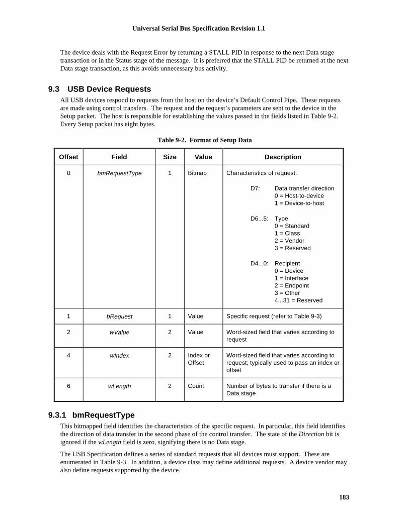
Universal Serial Bus Specification Revision 1.1
183
The device deals with the Request Error by returning a STALL PID in response to the next Data stagetransaction or in the Status stage of the message. It is preferred that the STALL PID be returned at the nextData stage transaction, as this avoids unnecessary bus activity.
9.3 USB Device RequestsAll USB devices respond to requests from the host on the device’s Default Control Pipe. These requestsare made using control transfers. The request and the request’s parameters are sent to the device in theSetup packet. The host is responsible for establishing the values passed in the fields listed in Table 9-2.Every Setup packet has eight bytes.
Table 9-2. Format of Setup Data
Offset Field Size Value Description
0 bmRequestType 1 Bitmap Characteristics of request:
D7: Data transfer direction0 = Host-to-device1 = Device-to-host
D6...5: Type0 = Standard1 = Class2 = Vendor3 = Reserved
D4...0: Recipient0 = Device1 = Interface2 = Endpoint3 = Other4...31 = Reserved
1 bRequest 1 Value Specific request (refer to Table 9-3)
2 wValue 2 Value Word-sized field that varies according torequest
4 wIndex 2 Index orOffset
Word-sized field that varies according torequest; typically used to pass an index oroffset
6 wLength 2 Count Number of bytes to transfer if there is aData stage
9.3.1 bmRequestTypeThis bitmapped field identifies the characteristics of the specific request. In particular, this field identifiesthe direction of data transfer in the second phase of the control transfer. The state of the Direction bit isignored if the wLength field is zero, signifying there is no Data stage.
The USB Specification defines a series of standard requests that all devices must support. These areenumerated in Table 9-3. In addition, a device class may define additional requests. A device vendor mayalso define requests supported by the device.

Universal Serial Bus Specification Revision 1.1
184
Requests may be directed to the device, an interface on the device, or a specific endpoint on a device. Thisfield also specifies the intended recipient of the request. When an interface or endpoint is specified, thewIndex field identifies the interface or endpoint.
9.3.2 bRequestThis field specifies the particular request. The Type bits in the bmRequestType field modify the meaning ofthis field. This specification defines values for the bRequest field only when the bits are reset to zero,indicating a standard request (refer to Table 9-3).
9.3.3 wValueThe contents of this field vary according to the request. It is used to pass a parameter to the device,specific to the request.
9.3.4 wIndexThe contents of this field vary according to the request. It is used to pass a parameter to the device,specific to the request.
The wIndex field is often used in requests to specify an endpoint or an interface. Figure 9-2 shows theformat of wIndex when it is used to specify an endpoint.
D7 D6 D5 D4 D3 D2 D1 D0
Direction Reserved (Reset to zero) Endpoint Number
D15 D14 D13 D12 D11 D10 D9 D8
Reserved (Reset to zero)
Figure 9-2. wIndex Format when Specifying an Endpoint
The Direction bit is set to zero to indicate the OUT endpoint with the specified Endpoint Number and toone to indicate the IN endpoint. In the case of a control pipe, the request should have the Direction bit setto zero but the device may accept either value of the Direction bit.
Figure 9-3 shows the format of wIndex when it is used to specify an interface.
D7 D6 D5 D4 D3 D2 D1 D0
Interface Number
D15 D14 D13 D12 D11 D10 D9 D8
Reserved (Reset to zero)
Figure 9-3. wIndex Format when Specifying an Interface
9.3.5 wLengthThis field specifies the length of the data transferred during the second phase of the control transfer. Thedirection of data transfer (host-to-device or device-to-host) is indicated by the Direction bit of thebmRequestType field. If this field is zero, there is no data transfer phase.

Universal Serial Bus Specification Revision 1.1
185
On an input request, a device must never return more data than is indicated by the wLength value; it mayreturn less. On an output request, wLength will always indicate the exact amount of data to be sent by thehost. Device behavior is undefined if the host should send more data than is specified in wLength.
9.4 Standard Device RequestsThis section describes the standard device requests defined for all USB devices. Table 9-3 outlines thestandard device requests, while Table 9-4 and Table 9-5 give the standard request codes and descriptortypes, respectively.
USB devices must respond to standard device requests, whether the device has been assigned a non-defaultaddress or the device is currently configured.

Universal Serial Bus Specification Revision 1.1
186
Table 9-3. Standard Device Requests
bmRequestType bRequest wValue wIndex wLength Data
00000000B00000001B00000010B
CLEAR_FEATURE FeatureSelector
ZeroInterfaceEndpoint
Zero None
10000000B GET_CONFIGURATION Zero Zero One ConfigurationValue
10000000B GET_DESCRIPTOR DescriptorType andDescriptor
Index
Zero orLanguage
ID
DescriptorLength
Descriptor
10000001B GET_INTERFACE Zero Interface One AlternateInterface
10000000B10000001B10000010B
GET_STATUS Zero ZeroInterfaceEndpoint
Two Device,Interface, or
EndpointStatus
00000000B SET_ADDRESS DeviceAddress
Zero Zero None
00000000B SET_CONFIGURATION ConfigurationValue
Zero Zero None
00000000B SET_DESCRIPTOR DescriptorType andDescriptor
Index
Zero orLanguage
ID
DescriptorLength
Descriptor
00000000B00000001B00000010B
SET_FEATURE FeatureSelector
ZeroInterfaceEndpoint
Zero None
00000001B SET_INTERFACE AlternateSetting
Interface Zero None
10000010B SYNCH_FRAME Zero Endpoint Two Frame Number
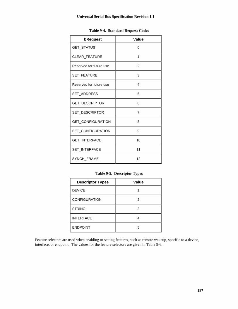
Universal Serial Bus Specification Revision 1.1
187
Table 9-4. Standard Request Codes
bRequest Value
GET_STATUS 0
CLEAR_FEATURE 1
Reserved for future use 2
SET_FEATURE 3
Reserved for future use 4
SET_ADDRESS 5
GET_DESCRIPTOR 6
SET_DESCRIPTOR 7
GET_CONFIGURATION 8
SET_CONFIGURATION 9
GET_INTERFACE 10
SET_INTERFACE 11
SYNCH_FRAME 12
Table 9-5. Descriptor Types
Descriptor Types Value
DEVICE 1
CONFIGURATION 2
STRING 3
INTERFACE 4
ENDPOINT 5
Feature selectors are used when enabling or setting features, such as remote wakeup, specific to a device,interface, or endpoint. The values for the feature selectors are given in Table 9-6.

Universal Serial Bus Specification Revision 1.1
188
Table 9-6. Standard Feature Selectors
Feature Selector Recipient Value
DEVICE_REMOTE_WAKEUP Device 1
ENDPOINT_HALT Endpoint 0
If an unsupported or invalid request is made to a USB device, the device responds by returning STALL inthe Data or Status stage of the request. If the device detects the error in the Setup stage, it is preferred thatthe device returns STALL at the earlier of the Data or Status stage. Receipt of an unsupported or invalidrequest does NOT cause the optional Halt feature on the control pipe to be set. If for any reason, thedevice becomes unable to communicate via its Default Control Pipe due to an error condition, the devicemust be reset to clear the condition and restart the Default Control Pipe.
9.4.1 Clear FeatureThis request is used to clear or disable a specific feature.
bmRequestType bRequest wValue wIndex wLength Data
00000000B00000001B00000010B
CLEAR_FEATURE FeatureSelector
ZeroInterfaceEndpoint
Zero None
Feature selector values in wValue must be appropriate to the recipient. Only device feature selector valuesmay be used when the recipient is a device, only interface feature selector values may be used when therecipient is an interface, and only endpoint feature selector values may be used when the recipient is anendpoint.
Refer to Table 9-6 for a definition of which feature selector values are defined for which recipients.
A ClearFeature() request that references a feature that cannot be cleared, that does not exist, or thatreferences an interface or endpoint that does not exist will cause the device to respond with a RequestError.
If wLength is non-zero, then the device behavior is not specified.
Default state: Device behavior when this request is received while the device is in the Default stateis not specified.
Address state: This request is valid when the device is in the Address state; references to interfacesor to endpoints other than endpoint zero shall cause the device to respond with aRequest Error.
Configured state: This request is valid when the device is in the Configured state.

Universal Serial Bus Specification Revision 1.1
189
9.4.2 Get ConfigurationThis request returns the current device configuration value.
bmRequestType bRequest wValue wIndex wLength Data
10000000B GET_CONFIGURATION Zero Zero One ConfigurationValue
If the returned value is zero, the device is not configured.
If wValue, wIndex, or wLength are not as specified above, then the device behavior is not specified.
Default state: Device behavior when this request is received while the device is in the Default stateis not specified.
Address state: The value zero shall be returned.
Configured state: The non-zero bConfigurationValue of the current configuration shall be returned.
9.4.3 Get DescriptorThis request returns the specified descriptor if the descriptor exists.
bmRequestType bRequest wValue wIndex wLength Data
10000000B GET_DESCRIPTOR DescriptorType andDescriptor
Index
Zero orLanguage ID
(refer toSection 9.6.5)
DescriptorLength
Descriptor
The wValue field specifies the descriptor type in the high byte and the descriptor index in the low byte(refer to Table 9-5). The wIndex field specifies the Language ID for string descriptors or is reset to zero forother descriptors. The wLength field specifies the number of bytes to return. If the descriptor is longerthan the wLength field, only the initial bytes of the descriptor are returned. If the descriptor is shorter thanthe wLength field, the device indicates the end of the control transfer by sending a short packet whenfurther data is requested. A short packet is defined as a packet shorter than the maximum payload size or aNULL data packet (refer to Chapter 5).
The standard request to a device supports three types of descriptors: DEVICE, CONFIGURATION, andSTRING. A request for a configuration descriptor returns the configuration descriptor, all interfacedescriptors, and endpoint descriptors for all of the interfaces in a single request. The first interfacedescriptor follows the configuration descriptor. The endpoint descriptors for the first interface follow thefirst interface descriptor. If there are additional interfaces, their interface descriptor and endpointdescriptors follow the first interface’s endpoint descriptors. Class-specific and/or vendor-specificdescriptors follow the standard descriptors they extend or modify.
All devices must provide a device descriptor and at least one configuration descriptor. If a device does notsupport a requested descriptor, it responds with a Request Error.
Default state: This is a valid request when the device is in the Default state.
Address state: This is a valid request when the device is in the Address state.

Universal Serial Bus Specification Revision 1.1
190
Configured state: This is a valid request when the device is in the Configured state.
9.4.4 Get InterfaceThis request returns the selected alternate setting for the specified interface.
bmRequestType bRequest wValue wIndex wLength Data
10000001B GET_INTERFACE Zero Interface One AlternateSetting
Some USB devices have configurations with interfaces that have mutually exclusive settings. This requestallows the host to determine the currently selected alternative setting.
If wValue or wLength are not as specified above, then the device behavior is not specified.
If the interface specified does not exist, then the device responds with a Request Error.
Default state: Device behavior when this request is received while the device is in the Default stateis not specified.
Address state: A Request Error response is given by the device.
Configured state: This is a valid request when the device is in the Configured state.
9.4.5 Get StatusThis request returns status for the specified recipient.
bmRequestType bRequest wValue wIndex wLength Data
10000000B10000001B10000010B
GET_STATUS Zero ZeroInterfaceEndpoint
Two Device,Interface, or
EndpointStatus
The Recipient bits of the bmRequestType field specify the desired recipient. The data returned is thecurrent status of the specified recipient.
If wValue or wLength are not as specified above, or if wIndex is non-zero for a device status request, thenthe behavior of the device is not specified.
If an interface or an endpoint is specified that does not exist then the device responds with a Request Error.
Default state: Device behavior when this request is received while the device is in the Default stateis not specified.
Address state: If an interface or an endpoint other than endpoint zero is specified, then the deviceresponds with a Request Error.
Configured state: If an interface or endpoint that does not exist is specified, then the device respondswith a Request Error.

Universal Serial Bus Specification Revision 1.1
191
A GetStatus() request to a device returns the information shown in Figure 9-4.
D7 D6 D5 D4 D3 D2 D1 D0
Reserved (Reset to zero) RemoteWakeup
SelfPowered
D15 D14 D13 D12 D11 D10 D9 D8
Reserved (Reset to zero)
Figure 9-4. Information Returned by a GetStatus() Request to a Device
The Self Powered field indicates whether the device is currently self-powered. If D0 is reset to zero, thedevice is bus-powered. If D0 is set to one, the device is self-powered. The Self Powered field may not bechanged by the SetFeature() or ClearFeature() requests.
The Remote Wakeup field indicates whether the device is currently enabled to request remote wakeup. Thedefault mode for devices that support remote wakeup is disabled. If D1 is reset to zero, the ability of thedevice to signal remote wakeup is disabled. If D1 is set to one, the ability of the device to signal remotewakeup is enabled. The Remote Wakeup field can be modified by the SetFeature() and ClearFeature()requests using the DEVICE_REMOTE_WAKEUP feature selector. This field is reset to zero when thedevice is reset.
A GetStatus() request to an interface returns the information shown in Figure 9-5.
D7 D6 D5 D4 D3 D2 D1 D0
Reserved (Reset to zero)
D15 D14 D13 D12 D11 D10 D9 D8
Reserved (Reset to zero)
Figure 9-5. Information Returned by a GetStatus() Request to a Interface

Universal Serial Bus Specification Revision 1.1
192
A GetStatus() request to an endpoint returns the information shown in Figure 9-6.
D7 D6 D5 D4 D3 D2 D1 D0
Reserved (Reset to zero) Halt
D15 D14 D13 D12 D11 D10 D9 D8
Reserved (Reset to zero)
Figure 9-6. Information Returned by a GetStatus() Request to an Endpoint
The Halt feature is required to be implemented for all interrupt and bulk endpoint types. If the endpoint iscurrently halted, then the Halt feature is set to one. Otherwise, the Halt feature is reset to zero. The Haltfeature may optionally be set with the SetFeature(ENDPOINT_HALT) request. When set by theSetFeature() request, the endpoint exhibits the same stall behavior as if the field had been set by a hardwarecondition. If the condition causing a halt has been removed, clearing the Halt feature via aClearFeature(ENDPOINT_HALT) request results in the endpoint no longer returning a STALL. Forendpoints using data toggle, regardless of whether an endpoint has the Halt feature set, aClearFeature(ENDPOINT_HALT) request always results in the data toggle being reinitialized to DATA0.The Halt feature is reset to zero after either a SetConfiguration() or SetInterface() request even if therequested configuration or interface is the same as the current configuration or interface.
It is neither required nor recommended that the Halt feature be implemented for the Default Control Pipe.However, devices may set the Halt feature of the Default Control Pipe in order to reflect a functional errorcondition. If the feature is set to one, the device will return STALL in the Data and Status stages of eachstandard request to the pipe except GetStatus(), SetFeature(), and ClearFeature() requests. The device neednot return STALL for class-specific and vendor-specific requests.
9.4.6 Set AddressThis request sets the device address for all future device accesses.
bmRequestType bRequest wValue wIndex wLength Data
00000000B SET_ADDRESS DeviceAddress
Zero Zero None
The wValue field specifies the device address to use for all subsequent accesses.
As noted elsewhere, requests actually may result in up to three stages. In the first stage, the Setup packet issent to the device. In the optional second stage, data is transferred between the host and the device. In thefinal stage, status is transferred between the host and the device. The direction of data and status transferdepends on whether the host is sending data to the device or the device is sending data to the host. TheStatus stage transfer is always in the opposite direction of the Data stage. If there is no Data stage, theStatus stage is from the device to the host.
Stages after the initial Setup packet assume the same device address as the Setup packet. The USB devicedoes not change its device address until after the Status stage of this request is completed successfully.Note that this is a difference between this request and all other requests. For all other requests, theoperation indicated must be completed before the Status stage.
If the specified device address is greater than 127, or if wIndex or wLength are non-zero, then the behaviorof the device is not specified.

Universal Serial Bus Specification Revision 1.1
193
Device response to SetAddress() with a value of 0 is undefined.
Default state: If the address specified is non-zero, then the device shall enter the Address state;otherwise, the device remains in the Default state (this is not an error condition).
Address state: If the address specified is zero, then the device shall enter the Default state;otherwise, the device remains in the Address state but uses the newly-specifiedaddress.
Configured state: Device behavior when this request is received while the device is in the Configuredstate is not specified.
9.4.7 Set ConfigurationThis request sets the device configuration.
bmRequestType bRequest wValue wIndex wLength Data
00000000B SET_CONFIGURATION Configuration Value Zero Zero None
The lower byte of the wValue field specifies the desired configuration. This configuration value must bezero or match a configuration value from a configuration descriptor. If the configuration value is zero, thedevice is placed in its Address state. The upper byte of the wValue field is reserved.
If wIndex, wLength, or the upper byte of wValue is non-zero, then the behavior of this request is notspecified.
Default state: Device behavior when this request is received while the device is in the Default stateis not specified.
Address state: If the specified configuration value is zero, then the device remains in the Addressstate. If the specified configuration value matches the configuration value from aconfiguration descriptor, then that configuration is selected and the device enters theConfigured state. Otherwise, the device responds with a Request Error.
Configured state: If the specified configuration value is zero, then the device enters the Address state.If the specified configuration value matches the configuration value from aconfiguration descriptor, then that configuration is selected and the device remains inthe Configured state. Otherwise, the device responds with aRequest Error.
9.4.8 Set DescriptorThis request may be used to update existing descriptors or new descriptors may be added.
bmRequestType bRequest wValue wIndex wLength Data
00000000B SET_DESCRIPTOR DescriptorType andDescriptor
Index
Language ID(refer to
Section 9.6.5)or zero
DescriptorLength
Descriptor

Universal Serial Bus Specification Revision 1.1
194
The wValue field specifies the descriptor type in the high byte and the descriptor index in the low byte(refer to Table 9-5). The wIndex field specifies the Language ID for string descriptors or is reset to zero forother descriptors. The wLength field specifies the number of bytes to transfer from the host to the device.
If this request is not supported then the device will respond with a Request Error.
Default state: Device behavior when this request is received while the device is in the Default stateis not specified.
Address state: If supported, this is a valid request when the device is in the Address state.
Configured state: If supported, this is a valid request when the device is in the Configured state.
9.4.9 Set FeatureThis request is used to set or enable a specific feature.
bmRequestType bRequest wValue wIndex wLength Data
00000000B00000001B00000010B
SET_FEATURE FeatureSelector
ZeroInterfaceEndpoint
Zero None
Feature selector values in wValue must be appropriate to the recipient. Only device feature selector valuesmay be used when the recipient is a device; only interface feature selector values may be used when therecipient is an interface, and only endpoint feature selector values may be used when the recipient is anendpoint.
Refer to Table 9-6 for a definition of which feature selector values are defined for which recipients. ASetFeature() request that references a feature that cannot be set or that does not exist causes a STALL to bereturned in the Status stage of the request.
If wLength is non-zero, then the behavior of the device is not specified.
If an endpoint or interface is specified that does not exist, then the device responds with a Request Error.
Default state: Device behavior when this request is received while the device is in the Default stateis not specified.
Address state: If an interface or an endpoint other than endpoint zero is specified, then the deviceresponds with a Request Error.
Configured state: This is a valid request when the device is in the Configured state.

Universal Serial Bus Specification Revision 1.1
195
9.4.10 Set InterfaceThis request allows the host to select an alternate setting for the specified interface.
bmRequestType bRequest wValue wIndex wLength Data
00000001B SET_INTERFACE AlternativeSetting
Interface Zero None
Some USB devices have configurations with interfaces that have mutually exclusive settings. This requestallows the host to select the desired alternate setting. If a device only supports a default setting for thespecified interface, then a STALL may be returned in the Status stage of the request.
If the interface or the alternative setting does not exist, then the device responds with a Request Error. IfwLength is non-zero, then the behavior of the device is not specified.
Default state: Device behavior when this request is received while the device is in the Default stateis not specified.
Address state: The device shall respond with a Request Error.
Configured state: This is a valid request when the device is in the Configured state.
9.4.11 Synch FrameThis request is used to set and then report an endpoint’s synchronization frame.
bmRequestType bRequest wValue wIndex wLength Data
10000010B SYNCH_FRAME Zero Endpoint Two FrameNumber
When an endpoint supports isochronous transfers, the endpoint may also require per-frame transfers tovary in size according to a specific pattern. The host and the endpoint must agree on which frame therepeating pattern begins. The number of the frame in which the pattern began is returned to the host. Thisframe number is the one conveyed to the endpoint by the last SOF prior to the first frame of the pattern.Alternatively, the device may use this request to restart the pattern. In this case, the device would save theframe number in each SOF and return this value in the Data stage of this transfer and restart the pattern oneach IN of the Data stage.
This value is only used for isochronous data transfers using implicit pattern synchronization. If wValue isnon-zero or wLength is not two, then the behavior of the device is not specified.
If the specified endpoint does not support this request, then the device will respond with a Request Error.
Default state: Device behavior when this request is received while the device is in the Default stateis not specified.
Address state: The device shall respond with a Request Error.
Configured state: This is a valid request when the device is in the Configured state.

Universal Serial Bus Specification Revision 1.1
196
9.5 DescriptorsUSB devices report their attributes using descriptors. A descriptor is a data structure with a defined format.Each descriptor begins with a byte-wide field that contains the total number of bytes in the descriptorfollowed by a byte-wide field that identifies the descriptor type.
Using descriptors allows concise storage of the attributes of individual configurations because eachconfiguration may reuse descriptors or portions of descriptors from other configurations that have the samecharacteristics. In this manner, the descriptors resemble individual data records in a relational database.
Where appropriate, descriptors contain references to string descriptors that provide displayable informationdescribing a descriptor in human-readable form. The inclusion of string descriptors is optional. However,the reference fields within descriptors are mandatory. If a device does not support string descriptors, stringreference fields must be reset to zero to indicate no string descriptor is available.
If a descriptor returns with a value in its length field that is less than defined by this specification, thedescriptor is invalid and should be rejected by the host. If the descriptor returns with a value in its lengthfield that is greater than defined by this specification, the extra bytes are ignored by the host, but the nextdescriptor is located using the length returned rather than the length expected.
A device may return class- or vendor-specific descriptors in two ways.
1. If the class or vendor specific descriptors use the same format as standard descriptors (e.g. start with alength byte and followed by a type byte), they may be returned interleaved with standard descriptors inthe configuration information returned by a GetDescriptor(Configuration) request. In this case, theclass or vendor-specific descriptors typically follow a related standard descriptor they modify orextend.
2. If the class or vendor specifric descriptors are independentof configuration infomrationor use a non-standard format, a GetDescriptor() request specifying the class or vendor specific descriptor type andindex may be used to retrieve the descriptor from the device. A class or vendor specification willdefine the appropriate way to retrieve these descriptors.
9.6 Standard USB Descriptor DefinitionsThe standard descriptors defined in this specification may only be modified or extended by revision of theUniversal Serial Bus Specification.
Note: An extension to the USB 1.0 standard endpoint descriptor has been published in Device ClassSpecification for Audio Devices Revision 1.0. This is the only extension defined outside USB Specificationthat is allowed. Future revisions of the USB Specification that extend the standard endpoint descriptor willdo so as to not conflict with the extension defined in the Audio Device Class Specification Revision 1.0.
9.6.1 DeviceA device descriptor describes general information about a USB device. It includes information that appliesglobally to the device and all of the device’s configurations. A USB device has only one device descriptor.
All USB devices have a Default Control Pipe. The maximum packet size of a device’s Default ControlPipe is described in the device descriptor. Endpoints specific to a configuration and its interface(s) aredescribed in the configuration descriptor. A configuration and its interface(s) do not include an endpointdescriptor for the Default Control Pipe. Other than the maximum packet size, the characteristics of theDefault Control Pipe are defined by this specification and are the same for all USB devices.
The bNumConfigurations field identifies the number of configurations the device supports. Table 9-7shows the standard device descriptor.

Universal Serial Bus Specification Revision 1.1
197
Table 9-7. Standard Device Descriptor
Offset Field Size Value Description
0 bLength 1 Number Size of this descriptor in bytes
1 bDescriptorType 1 Constant DEVICE Descriptor Type
2 bcdUSB 2 BCD USB Specification Release Number inBinary-Coded Decimal (i.e., 2.10 is 210H).This field identifies the release of the USBSpecification with which the device and itsdescriptors are compliant.
4 bDeviceClass 1 Class Class code (assigned by the USB).
If this field is reset to zero, each interfacewithin a configuration specifies its ownclass information and the variousinterfaces operate independently.
If this field is set to a value between 1 andFEH, the device supports different classspecifications on different interfaces andthe interfaces may not operateindependently. This value identifies theclass definition used for the aggregateinterfaces. (For example, a CD-ROMdevice with audio and digital datainterfaces that require transport control toeject CDs or start them spinning.)
If this field is set to FFH, the device classis vendor-specific.
5 bDeviceSubClass 1 SubClass Subclass code (assigned by the USB).
These codes are qualified by the value ofthe bDeviceClass field.
If the bDeviceClass field is reset to zero,this field must also be reset to zero.
If the bDeviceClass field is not set to FFH,all values are reserved for assignment bythe USB.
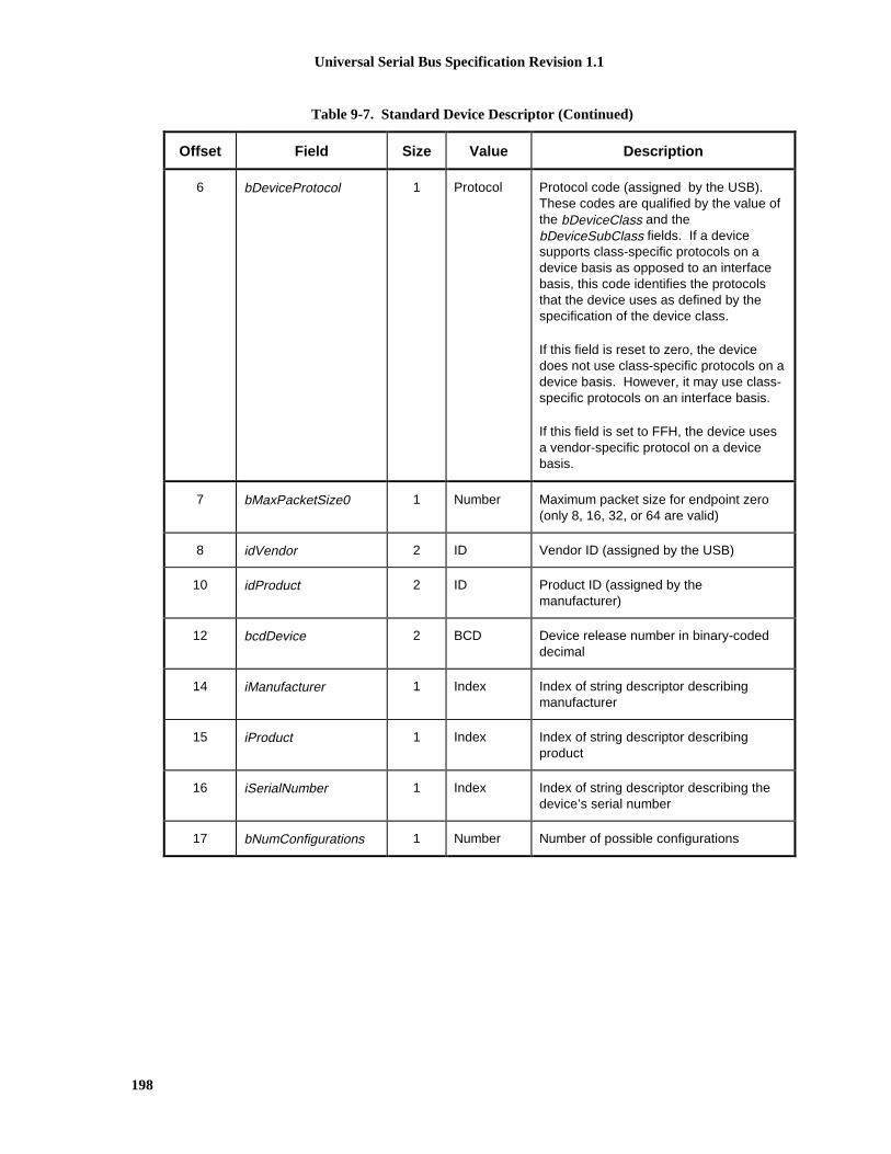
Universal Serial Bus Specification Revision 1.1
198
Table 9-7. Standard Device Descriptor (Continued)
Offset Field Size Value Description
6 bDeviceProtocol 1 Protocol Protocol code (assigned by the USB).These codes are qualified by the value ofthe bDeviceClass and thebDeviceSubClass fields. If a devicesupports class-specific protocols on adevice basis as opposed to an interfacebasis, this code identifies the protocolsthat the device uses as defined by thespecification of the device class.
If this field is reset to zero, the devicedoes not use class-specific protocols on adevice basis. However, it may use class-specific protocols on an interface basis.
If this field is set to FFH, the device usesa vendor-specific protocol on a devicebasis.
7 bMaxPacketSize0 1 Number Maximum packet size for endpoint zero(only 8, 16, 32, or 64 are valid)
8 idVendor 2 ID Vendor ID (assigned by the USB)
10 idProduct 2 ID Product ID (assigned by themanufacturer)
12 bcdDevice 2 BCD Device release number in binary-codeddecimal
14 iManufacturer 1 Index Index of string descriptor describingmanufacturer
15 iProduct 1 Index Index of string descriptor describingproduct
16 iSerialNumber 1 Index Index of string descriptor describing thedevice’s serial number
17 bNumConfigurations 1 Number Number of possible configurations

Universal Serial Bus Specification Revision 1.1
199
9.6.2 ConfigurationThe configuration descriptor describes information about a specific device configuration. The descriptorcontains a bConfigurationValue field with a value that, when used as a parameter to the SetConfiguration()request, causes the device to assume the described configuration.
The descriptor describes the number of interfaces provided by the configuration. Each interface mayoperate independently. For example, an ISDN device might be configured with two interfaces, eachproviding 64kB/s bi-directional channels that have separate data sources or sinks on the host. Anotherconfiguration might present the ISDN device as a single interface, bonding the two channels into one128kB/s bi-directional channel.
When the host requests the configuration descriptor, all related interface and endpoint descriptors arereturned (refer to Section 9.4.2).
A USB device has one or more configuration descriptors. Each configuration has one or more interfacesand each interface has zero or more endpoints. An endpoint is not shared among interfaces within a singleconfiguration unless the endpoint is used by alternate settings of the same interface. Endpoints may beshared among interfaces that are part of different configurations without this restriction.
Once configured, devices may support limited adjustments to the configuration. If a particular interfacehas alternate settings, an alternate may be selected after configuration. Table 9-8 shows the standardconfiguration descriptor.
Table 9-8. Standard Configuration Descriptor
Offset Field Size Value Description
0 bLength 1 Number Size of this descriptor in bytes
1 bDescriptorType 1 Constant CONFIGURATION Descriptor Type
2 wTotalLength 2 Number Total length of data returned for thisconfiguration. Includes the combined lengthof all descriptors (configuration, interface,endpoint, and class- or vendor-specific)returned for this configuration.
4 bNumInterfaces 1 Number Number of interfaces supported by thisconfiguration
5 bConfigurationValue 1 Number Value to use as an argument to theSetConfiguration() request to select thisconfiguration
6 iConfiguration 1 Index Index of string descriptor describing thisconfiguration

Universal Serial Bus Specification Revision 1.1
200
Table 9-8. Standard Configuration Descriptor (Continued)
Offset Field Size Value Description
7 bmAttributes 1 Bitmap Configuration characteristics
D7: Reserved (set to one)D6: Self-poweredD5: Remote WakeupD4...0: Reserved (reset to zero)
D7 is reserved and must be set to one forhistorical reasons.
A device configuration that uses power fromthe bus and a local source reports a non-zerovalue in MaxPower to indicate the amount ofbus power required and sets D6. The actualpower source at runtime may be determinedusing the GetStatus(DEVICE) request (seeSection 9.4.5).
If a device configuration supports remotewakeup, D5 is set to one.
8 MaxPower 1 mA Maximum power consumption of the USBdevice from the bus in this specificconfiguration when the device is fullyoperational. Expressed in 2mA units (i.e., 50= 100mA).
Note: a device configuration reports whetherthe configuration is bus-powered or self-powered. Device status reports whether thedevice is currently self-powered. If a device isdisconnected from its external power source,it updates device status to indicate that it is nolonger self-powered.
A device may not increase its power drawfrom the bus, when it loses its external powersource, beyond the amount reported by itsconfiguration.
If a device can continue to operate whendisconnected from its external power source,it continues to do so. If the device cannotcontinue to operate, it fails operations it canno longer support. The USB System Softwaremay determine the cause of the failure bychecking the status and noting the loss of thedevice’s power source.

Universal Serial Bus Specification Revision 1.1
201
9.6.3 InterfaceThis descriptor describes a specific interface within a configuration. A configuration provides one or moreinterfaces, each with zero or more endpoint descriptors describing a unique set of endpoints within theconfiguration. When a configuration supports more than one interface, the endpoints for a particularinterface follow the interface descriptor in the data returned by the GetConfiguration() request. Aninterface descriptor is always returned as part of a configuration descriptor. Interface descriptors cannot bedirectly accessed with a GetDescriptor() or SetDescriptor() request.
An interface may include alternate settings that allow the endpoints and/or their characteristics to be variedafter the device has been configured. The default setting for an interface is always alternate setting zero.The SetInterface() request is used to select an alternate setting or to return to the default setting. TheGetInterface() request returns the selected alternate setting.
Alternate settings allow a portion of the device configuration to be varied while other interfaces remain inoperation. If a configuration has alternate settings for one or more of its interfaces, a separate interfacedescriptor and its associated endpoints are included for each setting.
If a device configuration supported a single interface with two alternate settings, the configurationdescriptor would be followed by an interface descriptor with the bInterfaceNumber and bAlternateSettingfields set to zero and then the endpoint descriptors for that setting, followed by another interface descriptorand its associated endpoint descriptors. The second interface descriptor’s bInterfaceNumber field wouldalso be set to zero, but the bAlternateSetting field of the second interface descriptor would be set to one.
If an interface uses only endpoint zero, no endpoint descriptors follow the interface descriptor and theinterface identifies a request interface that uses the default pipe attached to endpoint zero. In this case, thebNumEndpoints field shall be set to zero.
An interface descriptor never includes endpoint zero in the number of endpoints. Table 9-9 shows thestandard interface descriptor.

Universal Serial Bus Specification Revision 1.1
202
Table 9-9. Standard Interface Descriptor
Offset Field Size Value Description
0 bLength 1 Number Size of this descriptor in bytes
1 bDescriptorType 1 Constant INTERFACE Descriptor Type
2 bInterfaceNumber 1 Number Number of interface. Zero-based valueidentifying the index in the array ofconcurrent interfaces supported by thisconfiguration.
3 bAlternateSetting 1 Number Value used to select alternate setting forthe interface identified in the prior field
4 bNumEndpoints 1 Number Number of endpoints used by thisinterface (excluding endpoint zero). If thisvalue is zero, this interface only uses theDefault Control Pipe.
5 bInterfaceClass 1 Class Class code (assigned by the USB).
A value of zero is reserved for futurestandardization.
If this field is set to FFH, the interfaceclass is vendor-specific.
All other values are reserved forassignment by the USB.
6 bInterfaceSubClass 1 SubClass Subclass code (assigned by the USB).These codes are qualified by the value ofthe bInterfaceClass field.
If the bInterfaceClass field is reset tozero, this field must also be reset to zero.
If the bInterfaceClass field is not set toFFH, all values are reserved forassignment by the USB.

Universal Serial Bus Specification Revision 1.1
203
Table 9-9. Standard Interface Descriptor (Continued)
Offset Field Size Value Description
7 bInterfaceProtocol 1 Protocol Protocol code (assigned by the USB).These codes are qualified by the value ofthe bInterfaceClass and thebInterfaceSubClass fields. If an interfacesupports class-specific requests, thiscode identifies the protocols that thedevice uses as defined by thespecification of the device class.
If this field is reset to zero, the devicedoes not use a class-specific protocol onthis interface.
If this field is set to FFH, the device usesa vendor-specific protocol for thisinterface.
8 iInterface 1 Index Index of string descriptor describing thisinterface
9.6.4 EndpointEach endpoint used for an interface has its own descriptor. This descriptor contains the informationrequired by the host to determine the bandwidth requirements of each endpoint. An endpoint descriptor isalways returned as part of the configuration information returned by a GetDescriptor(Configuration)request. An endpoint descriptor cannot be directly accessed with a GetDescriptor() or SetDescriptor()request. There is never an endpoint descriptor for endpoint zero. Table 9-10 shows the standard endpointdescriptor.
Table 9-10. Standard Endpoint Descriptor
Offset Field Size Value Description
0 bLength 1 Number Size of this descriptor in bytes
1 bDescriptorType 1 Constant ENDPOINT Descriptor Type
2 bEndpointAddress 1 Endpoint The address of the endpoint on the USBdevice described by this descriptor. Theaddress is encoded as follows:
Bit 3...0: The endpoint numberBit 6...4: Reserved, reset to zeroBit 7: Direction, ignored for
control endpoints 0 = OUT endpoint 1 = IN endpoint

Universal Serial Bus Specification Revision 1.1
204
Table 9-10. Standard Endpoint Descriptor (Continued)
Offset Field Size Value Description
3 bmAttributes 1 Bitmap This field describes the endpoint’sattributes when it is configured using thebConfigurationValue.
Bit 1..0: Transfer Type 00 = Control 01 = Isochronous 10 = Bulk 11 = Interrupt
All other bits are reserved.
4 wMaxPacketSize 2 Number Maximum packet size this endpoint iscapable of sending or receiving when thisconfiguration is selected.
For isochronous endpoints, this value isused to reserve the bus time in theschedule, required for the per-frame datapayloads. The pipe may, on an ongoingbasis, actually use less bandwidth thanthat reserved. The device reports, ifnecessary, the actual bandwidth used viaits normal, non-USB defined mechanisms.
For interrupt, bulk, and control endpoints,smaller data payloads may be sent, butwill terminate the transfer and may or maynot require intervention to restart. Referto Chapter 5 for more information.
6 bInterval 1 Number Interval for polling endpoint for datatransfers. Expressed in milliseconds.
This field is ignored for bulk and controlendpoints. For isochronous endpointsthis field must be set to 1. For interruptendpoints, this field may range from 1 to255.
9.6.5 StringString descriptors are optional. As noted previously, if a device does not support string descriptors, allreferences to string descriptors within device, configuration, and interface descriptors must be reset to zero.
String descriptors use UNICODE encodings as defined by The Unicode Standard, Worldwide CharacterEncoding, Version 1.0, Volumes 1 and 2, The Unicode Consortium, Addison-Wesley Publishing Company,Reading, Massachusetts. The strings in a USB device may support multiple languages. When requesting astring descriptor, the requester specifies the desired language using a sixteen-bit language ID (LANGID)defined by Microsoft for Windows as described in Developing International Software for Windows 95 andWindows NT, Nadine Kano, Microsoft Press, Redmond, Washington. String index zero for all languagesreturns a string descriptor that contains an array of two-byte LANGID codes supported by the device.Table 9-11 shows the LANGID code array. A USB device may omit all string descriptors. USB devicesthat omit all string descriptors shall not return an array of LANGID codes.

Universal Serial Bus Specification Revision 1.1
205
The array of LANGID codes is not NULL-terminated. The size of the array (in bytes) is computed bysubtracting two from the value of the first byte of the descriptor.
Table 9-11. Codes Representing Languages Supported by the Device
Offset Field Size Value Description
0 bLength 1 N+2 Size of this descriptor in bytes
1 bDescriptorType 1 Constant STRING Descriptor Type
2 wLANGID[0] 2 Number LANGID code zero
... ... ... ... ...
N wLANGID[x] 2 Number LANGID code x
The UNICODE string descriptor (shown in Table 9-12) is not NULL-terminated. The string length iscomputed by subtracting two from the value of the first byte of the descriptor.
Table 9-12. UNICODE String Descriptor
Offset Field Size Value Description
0 bLength 1 Number Size of this descriptor in bytes
1 bDescriptorType 1 Constant STRING Descriptor Type
2 bString N Number UNICODE encoded string
9.7 Device Class DefinitionsAll devices must support the requests and descriptor definitions described in this chapter. Most devicesprovide additional requests and, possibly, descriptors for device-specific extensions. In addition, devicesmay provide extended services that are common to a group of devices. In order to define a class ofdevices, the following information must be provided to completely define the appearance and behavior ofthe device class.
9.7.1 DescriptorsIf the class requires any specific definition of the standard descriptors, the class definition must includethose requirements as part of the class definition. In addition, if the class defines a standard extended set ofdescriptors, they must also be fully defined in the class definition. Any extended descriptor definitionsshould follow the approach used for standard descriptors; for example, all descriptors should begin with alength field.
9.7.2 Interface(s) and Endpoint UsageWhen a class of devices is standardized, the interfaces used by the devices, including how endpoints areused, must be included in the device class definition. Devices may further extend a class definition withproprietary features as long as they meet the base definition of the class.

Universal Serial Bus Specification Revision 1.1
206
9.7.3 RequestsAll of the requests specific to the class must be defined.

Universal Serial Bus Specification Revision 1.1
207
Chapter 10USB Host: Hardware and Software
The USB interconnect supports data traffic between a host and a USB device. This chapter describes thehost interfaces necessary to facilitate USB communication between a software client, resident on the host,and a function implemented on a device. The implementation described in this chapter is not required. Thisimplementation is provided as an example to illustrate the host system behavior expected by a USB device.A host system may provide a different host software implementation as long as a USB device experiencesthe shame host behavior.
10.1 Overview of the USB Host
10.1.1 OverviewThe basic flow and interrelationships of the USB communications model are shown in Figure 10-1
Client
USB BusInterface
USB Device
Function
Host DeviceInterconnect
USB BusInterface
USB System
Actual communications flow
Logical communications flow
Figure 10-1. Interlayer Communications Model
The host and the device are divided into the distinct layers depicted in Figure 10-1. Vertical arrowsindicate the actual communication on the host. The corresponding interfaces on the device areimplementation-specific. All communications between the host and device ultimately occur on thephysical USB wire. However, there are logical host-device interfaces between each horizontal layer.These communications, between client software resident on the host and the function provided by thedevice, are typified by a contract based on the needs of the application currently using the device and thecapabilities provided by the device.
This client-function interaction creates the requirements for all of the underlying layers and their interfaces.

Universal Serial Bus Specification Revision 1.1
208
This chapter describes this model from the point of view of the host and its layers. Figure 10-2 describes,based on the overall view introduced in Chapter 5, the host’s view of its communication with the device.
SIEHost
Controller
USB BusInterface
USB Systemmanages pipes
InterconnectHost
USB Wire
IRPs
Default Pipe
to Endpoint Zero
Pipe Bundle
to an interface
Pipe: Represents connectionabstraction between two horizontallayers
Interprocess Communication
HC-Defined
Client
manages interfaces
USB Driver HostSoftware
HC Driver
Configuration
HW-Defined
OptionalComponent
Figure 10-2. Host Communications

Universal Serial Bus Specification Revision 1.1
209
There is only one host for each USB. The major layers of a host consist of the following:
� USB bus interface
� USB System
� Client.
The USB bus interface handles interactions for the electrical and protocol layers (refer to Chapter 7 andChapter 8). From the interconnect point of view, a similar USB bus interface is provided by both the USBdevice and the host, as exemplified by the Serial Interface Engine (SIE). On the host, however, the USBbus interface has additional responsibilities due to the unique role of the host on the USB and isimplemented as the Host Controller. The Host Controller has an integrated root hub providing attachmentpoints to the USB wire.
The USB System uses the Host Controller to manage data transfers between the host and USB devices.The interface between the USB System and the Host Controller is dependent on the hardware definition ofthe Host Controller. The USB System, in concert with the Host Controller, performs the translationbetween the client’s view of data transfers and the USB transactions appearing on the interconnect. Thisincludes the addition of any USB feature support such as protocol wrappers. The USB System is alsoresponsible for managing USB resources, such as bandwidth and bus power, so that client access to theUSB is possible.
The USB System has three basic components:
� Host Controller Driver
� USB Driver
� Host Software.
The Host Controller Driver (HCD) exists to more easily map the various Host Controller implementationsinto the USB System, such that a client can interact with its device without knowing to which HostController the device is connected. The USB Driver (USBD) provides the basic host interface (USBDI) forclients to USB devices. The interface between the HCD and the USBD is known as the Host ControllerDriver Interface (HCDI). This interface is never available directly to clients and thus is not defined by theUSB Specification. A particular HCDI is, however, defined by each operating system that supports variousHost Controller implementations.
The USBD provides data transfer mechanisms in the form of I/O Request Packets (IRPs), which consist ofa request to transport data across a specific pipe. In addition to providing data transfer mechanisms, theUSBD is responsible for presenting to its clients an abstraction of a USB device that can be manipulated forconfiguration and state management. As part of this abstraction, the USBD owns the default pipe (seeChapter 5 and Chapter 9) through which all USB devices are accessed for the purposes of standard USBcontrol. This default pipe represents a logical communication between the USBD and the abstraction of aUSB device as shown in Figure 10-2.
In some operating systems, additional non-USB System Software is available that provides configurationand loading mechanisms to device drivers. In such operating systems, the device driver shall use theprovided interfaces instead of directly accessing the USBDI mechanisms.
The client layer describes all the software entities that are responsible for directly interacting with USBdevices. When each device is attached to the system, these clients might interact directly with theperipheral hardware. The shared characteristics of the USB place USB System Software between the clientand its device; that is, a client cannot directly access the device’s hardware.

Universal Serial Bus Specification Revision 1.1
210
Overall, the host layers provide the following capabilities:
� Detecting the attachment and removal of USB devices
� Managing USB standard control flow between the host and USB devices
� Managing data flow between the host and USB devices
� Collecting status and activity statistics
� Controlling the electrical interface between the Host Controller and USB devices, including theprovision of a limited amount of power.
The following sections describe these responsibilities and the requirements placed on the USBDI in greaterdetail. The actual interfaces used for a specific combination of host platform and operating system aredescribed in the appropriate operating system environment guide.
All hubs (see Chapter 11) report internal status changes and their port change status via the status changepipe. This includes a notification of when a USB device is attached to or removed from one of their ports.A USBD client generically known as the hub driver receives these notifications as owner of the hub’sStatus Change pipe. For device attachments, the hub driver then initiates the device configuration process.In some systems, this hub driver is a part of the host software provided by the operating system formanaging devices.
10.1.2 Control MechanismsControl information may be passed between the host and a USB device using in-band or out-of-bandsignaling. In-band signaling mixes control information with data in a pipe outside the awareness of thehost. Out-of-band signaling places control information in a separate pipe.
There is a message pipe called the default pipe for each attached USB device. This logical associationbetween a host and a USB device is used for USB standard control flow such as device enumeration andconfiguration. The default pipe provides a standard interface to all USB devices. The default pipe mayalso be used for device-specific communications, as mediated by the USBD, which owns the default pipesof all of the USB devices.
A particular USB device may allow the use of additional message pipes to transfer device-specific controlinformation. These pipes use the same communications protocol as the default pipe, but the informationtransferred is specific to the USB device and is not standardized by the USB Specification.
The USBD supports the sharing of the default pipe, which it owns and uses, with its clients. It alsoprovides access to any other control pipes associated with the device.
10.1.3 Data FlowThe Host Controller is responsible for transferring streams of data between the host and USB devices.These data transfers are treated as a continuous stream of bytes. The USB supports four basic types of datatransfers:
� Control transfers
� Isochronous transfers
� Interrupt transfers
� Bulk transfers.
For additional information on transfer types, refer to Chapter 5.
Each device presents one or more interfaces that a client may use to communicate with the device. Eachinterface is composed of zero or more pipes that individually transfer data between the client and aparticular endpoint on the device. The USBD establishes interfaces and pipes at the explicit request of theHost Software. The Host Controller provides service based on parameters provided by the Host Softwarewhen the configuration request is made.

Universal Serial Bus Specification Revision 1.1
211
A pipe has several characteristics based on the delivery requirements of the data to be transferred.Examples of these characteristics include the following:
� the rate at which data needs to be transferred
� whether data is provided at a steady rate or sporadically
� how long data may be delayed before delivery
� whether the loss of data being transferred is catastrophic.
A USB device endpoint describes the characteristics required for a specific pipe. Endpoints are describedas part of a USB device’s characterization information. For additional details, refer to Chapter 9.
10.1.4 Collecting Status and Activity StatisticsAs a common communicant for all control and data transfers between the host and USB devices, the USBSystem and the Host Controller are well-positioned to track status and activity information. Suchinformation is provided upon request to the Host Software, allowing that software to manage status andactivity information. This specification does not identify any specific information that should be tracked orrequire any particular format for reporting activity and status information.
10.1.5 Electrical Interface ConsiderationsThe host provides power to USB devices attached to the root hub. The amount of power provided by a portis specified in Chapter 7.
10.2 Host Controller RequirementsIn all implementations, Host Controllers perform the same basic duties with regard to the USB and itsattached devices. These basic duties are described below.
The Host Controller has requirements from both the host and the USB. The following is a brief overviewof the functionality provided. Each capability is discussed in detail in subsequent sections.
State Handling As a component of the host, the Host Controller reports and managesits states.
Serializer/Deserializer For data transmitted from the host, the Host Controller convertsprotocol and data information from its native format to a bit streamtransmitted on the USB. For data being received into the host, thereverse operation is performed.
Frame Generation The Host Controller produces SOF tokens at a period of 1ms.
Data Processing The Host Controller processes requests for data transmission to andfrom the host.
Protocol Engine The Host Controller supports the protocol specified by the USB.
Transmission ErrorHandling
All Host Controllers exhibit the same behavior when detecting andreacting to the defined error categories.
Remote Wakeup All host controlers must have the ability to place the bus into theSuspended state and to respond to bus wakeup events.
Root Hub The root hub provides standard hub function to link the HostController to one or more USB ports.

Universal Serial Bus Specification Revision 1.1
212
Host System Interface Provides a high-speed data path between the Host Controller and hostsystem.
The following sections present a more detailed discussion of the required capabilities of the HostController.
10.2.1 State HandlingThe Host Controller has a series of states that the USB System manages. Additionally, the Host Controllerprovides the interface to the following two areas of USB-relevant state:
� State change propagation
� Root hub.
The root hub presents to the hub driver the same standard states as other USB devices. The Host Controllersupports these states and their transitions for the hub. For detailed discussions of USB states, includingtheir interrelations and transitions, refer to Chapter 9.
The overall state of the Host Controller is inextricably linked with that of the root hub and of the overallUSB. Any Host Controller state changes that are visible to attached devices must be reflected in thecorresponding device state change information such that the resulting Host Controller and device states areconsistent.
USB devices request a wakeup through the use of resume signaling (refer to Chapter 7), devices to return totheir configured state. The Host Controller itself may cause a resume event through the same signalingmethod. The Host Controller must notify the rest of the host of a resume event through a mechanism ormechanisms specific to that system’s implementation.
10.2.2 Serializer/DeserializerThe actual transmission of data across the physical USB takes places as a serial bit stream. A SerialInterface Engine (SIE), whether implemented as part of the host or a USB device, handles the serializationand deserialization of USB transmissions. On the host, this SIE is part of the Host Controller.
10.2.3 Frame GenerationIt is the Host Controller’s responsibility to partition USB time into 1ms quantities called “frames.” Framesare created by the Host Controller through issuing Start-of-Frame (SOF) tokens at 1.00ms intervals asshown in Figure 10-3. The SOF token is the first transmission in the frame period. After issuing a SOFtoken, the Host Controller is free to transmit other transactions for the remainder of the frame period.When the Host Controller is in its normal operating state, SOF tokens must be continuously generated atthe 1ms periodic rate, regardless of the other bus activity or lack thereof. If the Host Controller enters astate where it is not providing power on the bus , it must not generate SOFs. When the Host Controller isnot generating SOFs, it may enter a power-reduced state.
S O F
Frame N+1
S O FS O F
Frame N
S O F
Frame N-1
EOF Interval (Frame N-1) EOF Interval (Frame N) EOF Interva l (Frame N+1)
Figure 10-3. Frame Creation
The SOF token holds the highest priority access to the bus. Babble circuitry in hubs electrically isolatesany active transmitters during the End-of-Frame (EOF) interval, providing an idle bus for the SOFtransmission.

Universal Serial Bus Specification Revision 1.1
213
The Host Controller must allow the length of the USB frame to be adjusted by ±1 bit time (refer to Section10.5.3.2.4). The Host Controller maintains the current frame number that may be read by the USB System.
The following apply to the current frame number:
� Used to uniquely identify one frame from another
� Incremented at the end of every frame period
� Valid through the subsequent frame.
The host transmits the lower 11 bits of the current frame number in each SOF token transmission. Whenrequested from the Host Controller, the current frame number is the frame number in existence at the timethe request was fulfilled. The current frame number as returned by the host (Host Controller or HCD) is atleast 32 bits, although the Host Controller itself is not required to maintain more than 11 bits.
The Host Controller shall cease transmission during the EOF interval. When the EOF interval begins, anytransactions scheduled specifically for the frame that has just passed are retired. If the Host Controller isexecuting a transaction at the time the EOF interval is encountered, the Host Controller terminates thetransaction.
10.2.4 Data ProcessingThe Host Controller is responsible for receiving data from the USB System and sending it to the USB andfor receiving data from the USB and sending it to the USB System. The particular format used for the datacommunications between the USB System and the Host Controller is implementation specific, within therules for transfer behavior described in Chapter 5.
10.2.5 Protocol EngineThe Host Controller manages the USB protocol level interface. It inserts the appropriate protocolinformation for outgoing transmissions. It also strips and interprets, as appropriate, the incoming protocolinformation.
10.2.6 Transmission Error HandlingThe Host Controller must be capable of detecting the following transmission error conditions, which aredefined from the host’s point of view:
� Timeout conditions after a host-transmitted token or packet. These errors occur when the addressedendpoint is unresponsive or when the structure of the transmission is so badly damaged that thetargeted endpoint does not recognize it.
� Data errors resulting in missing or invalid transmissions:
� The Host Controller sends or receives a packet shorter than that required for the transmission; forexample, a transmission extending beyond EOF or a lack of resources available to the HostController.
� An invalid CRC field on a received data packet.
Universal Serial Bus Specification Revision 1.1
214
� Protocol errors:
� An invalid handshake PID, such as a malformed or inappropriate handshake
� A false EOP
� A bit stuffing error.
For each bulk, command, and interrupt transaction, the host must maintain an error count tally. Errorsresult from the conditions described above, not as a result of an endpoint NAKing a request. This valuereflects the number of times the transaction has encountered a transmission error. If the error count tallyfor a given transaction reaches three, the host retires the transfer. When a transfer is retired due toexcessive errors, the last error type will be indicated. Isochronous transactions are attempted only once,regardless of outcome, and, therefore, no error count is maintained for this type.
10.2.7 Remote WakeupIf USB System wishes to place the bus in the Suspended state, it commands the Host Controller to stop allbus traffic, including SOFs. This causes all USB devices to enter the Suspended state. In this state, theUSB System may enable the Host Controller to respond to bus wakeup events. This allows the HostController to respond to bus wakeup signaling to restart the host system.
10.2.8 Root HubThe root hub provides the connection between the Host Controller and one or more USB ports. The roothub provides the same functionality as other hubs (See Chapter 11), except that the hardware and softwareinterface between the root hub and the Host Controller is defined by the specific hardware implementation.
10.2.8.1 Port ResetsSection 7.1.7.3 describes the requirements of a hub to ensure all upstream resume attempts areoverpowered with a long reset downstream. Root hubs may provide an aggregate reset period of at least50ms. If the reset duration is controlled in hardware and the hardware timer is <50ms, the USB System canissue several consecutive resets to accumulate a sufficiently long reset to the device.
10.2.9 Host System InterfaceThe Host Controller provides a high-speed bus-mastering interface to and from main system memory. Thephysical transfer between memory and the USB wire is performed automatically by the Host Controller.When data buffers need to be filled or emptied, the Host Controller informs the USB System.
10.3 Overview of Software MechanismsThe HCD and the USBD present software interfaces based on different levels of abstraction. They are,however, expected to operate together in a specified manner to satisfy the overall requirements of the USBSystem (see Figure 10-2). The requirements for the USB System are expressed primarily as requirementsfor the USBDI. The division of duties between the USBD and the HCD is not defined. However, the onerequirement of the HCDI that must be met is that it supports, in the specified operating system context,multiple Host Controller implementations.
The HCD provides an abstraction of the Host Controller and an abstraction of the Host Controller’s view ofdata transfer across the USB. The USBD provides an abstraction of the USB device and of the datatransfers between the client of the USBD and the function on the USB device. Overall, the USB Systemacts as a facilitator for transmitting data between the client and the function and as a control point for theUSB-specific interfaces of the USB device. As part of facilitating data transfer, the USB System providesbuffer management capabilities and allows the synchronization of the data transmittal to the needs of theclient and the function.

Universal Serial Bus Specification Revision 1.1
215
The specific requirements for the USBDI are described later in this chapter. The exact functions that fulfillthese requirements are described in the relevant operating system environment guide for the HCDI and theUSBDI. The procedures involved in accomplishing data transfers via the USBDI are described in thefollowing sections.
10.3.1 Device ConfigurationDifferent operating system environments perform device configuration using different softwarecomponents and different sequences of events. The USB System does not assume a specific operatingsystem method. However, there are some basic requirements that must be fulfilled by any USB Systemimplementation. In some operating systems existing host software provides these requirements. In others,the USB System provides the capabilities.
The USB System assumes a specialized client of the USBD, called a hub driver, that acts as aclearinghouse for the addition and removal of devices from a particular hub. Once the hub driver receivessuch notifications, it will employ additional host software and other USBD clients, in an operating systemspecific manner, to recognize and configure the device. This model, shown in Figure 10-4, is the basis ofthe following discussion.
DeviceDriver
HCD
USBD
Host SoftwareConfiguration
Support
ConfigurationControl
OptionalConfigurationControl
HubDriver
OptionalComponent
Figure 10-4. Configuration Interactions
When a device is attached, the hub driver receives a notification from the hub detecting the change. Thehub driver, using the information provided by the hub, requests a device identifier from the USBD. TheUSBD in turn sets up the default pipe for that device and returns a device identifier to the hub driver.

Universal Serial Bus Specification Revision 1.1
216
The device is now ready to be configured for use. For each device, there are three configurations that mustbe complete before that device is ready for use:
1. Device Configuration: This includes setting up all of the device’s USB parameters and allocating allUSB host resources that are visible to the device. This is accomplished by setting the configurationvalue on the device. A limited set of configuration changes, such as alternate settings, is allowedwithout totally reconfiguring the device. Once the device is configured, it is, from its point of view,ready for use.
2. USB Configuration: In order to actually create a USBD pipe ready for use by a client, additional USBinformation, not visible to the device, must be specified by the client. This information, known as thePolicy for the pipe, describes how the client will use the pipe. This includes such items as themaximum amount of data the client will transfer with one IRP, the maximum service interval the clientwill use, the client’s notification identification, and so on.
3. Function Configuration: Once configuration types 1 and 2 have been accomplished, the pipe iscompletely ready for use from the USB’s point of view. However, additional vendor- or class-specificsetup may be required before the client can actually use the pipe. This configuration is a private matterbetween the device and the client and is not standardized by the USBD.
The following paragraphs describe the device and USB configuration requirements.
The responsible configuring software performs the actual device configuration. Depending on theparticular operating system implementation, the software responsible for configuration can include thefollowing:
� The hub driver
� Other host software
� A device driver.
The configuring software first reads the device descriptor, then requests the description for each possibleconfiguration. It may use the information provided to load a particular client, such as a device driver,which initially interacts with the device. The configuring software, perhaps with input from that devicedriver, chooses a configuration for the device. Setting the device configuration sets up all of the endpointson the device and returns a collection of interfaces to be used for data transfer by USBD clients. Eachinterface is a collection of pipes owned by a single client.
This initial configuration uses the default settings for interfaces and the default bandwidth for eachendpoint. A USBD implementation may additionally allow the client to specify alternate interfaces whenselecting the initial configuration. The USB System will verify that the resources required for the supportof the endpoint are available and, if so, will allocate the bandwidth required. Refer to Section 10.3.2 for adiscussion of resource management.
The device is now configured, but the created pipes are not yet ready for use. The USB configuration isaccomplished when the client initializes each pipe by setting a Policy to specify how it will interact withthe pipe. Among the information specified is the client’s maximum service interval and notificationinformation. Among the actions taken by the USB System, as a result of setting the Policy, is determiningthe amount of buffer working space required beyond the data buffer space provided by the client. The sizeof the buffers required is based upon the usage chosen by the client and upon the per-transfer needs of theUSB System.
The client receives notifications when IRPs complete, successfully or due to errors. The client may alsowake up independently of USB notification to check the status of pending IRPs.
The client may also choose to make configuration modifications, such as enabling an alternate setting foran interface or changing the bandwidth allocated to a particular pipe. In order to perform these changes,the interface or pipe, respectively, must be idle.

Universal Serial Bus Specification Revision 1.1
217
10.3.2 Resource ManagementWhenever a pipe is setup by the USBD for a given endpoint, the USB System must determine if it cansupport the pipe. The USB System makes this determination based on the requirements stated in theendpoint descriptor. One of the endpoint requirements, which must be supported in order to create a pipefor an endpoint, is the bandwidth necessary for that endpoint’s transfers. There are two stages to check foravailable bandwidth. First the maximum execution time for a transaction is calculated. Then, the frameschedule is consulted to determine if the indicated transaction will fit.
The allocation of the guaranteed bandwidth for isochronous and interrupt pipes, and the determination ofwhether a particular control or bulk transaction will fit into a given frame, can be determined by a softwareheuristic in the USB System. If the actual transaction execution time in the Host Controller exceeds theheuristically determined value, the Host Controller is responsible for ensuring that frame integrity ismaintained (refer to Section 10.2.3). The following discussion describes the requirements for the USBSystem heuristic.
In order to determine if bandwidth can be allocated, or if a transaction can be fit into a particular frame, themaximum transaction execution time must be calculated. The calculation of the maximum transactionexecution time requires that the following information be provided. (Note that an agent other than theclient may provide some of this information.)
� Number of data bytes (wMaxPacketSize) to be transmitted.
� Transfer type.
� Depth in the topology. If less precision is allowed, the maximum topology depth may be assumed.
This calculation must include the bit transmission time, the signal propagation delay through the topology,and any implementation-specific delays, such as preparation or recovery time required by the HostController itself. Refer to Chapter 5 for examples of formulas that can be used for such calculations.
10.3.3 Data TransfersThe basis for all client-function communication is the interface: a bundle of related pipes associated with aparticular USB device.
Exactly one client on the host manages a given interface. The client initializes each pipe of an interface bysetting the Policy for that pipe. This includes the maximum amount of data to be transmitted per IRP andthe maximum service interval for the pipe. A service interval is stated in milliseconds and describes theinterval over which an IRP’s data will be transmitted for an isochronous pipe. It describes the pollinginterval for an interrupt pipe. The client is notified when a specified request is completed. The clientmanages the size of each IRP such that its duty cycle and latency constraints are maintained. AdditionalPolicy information includes the notification information for the client.
The client provides the buffer space required to hold the transmitted data. The USB System uses the Policyto determine the additional working space it will require.
The client views its data as a contiguous serial stream, which it manages in a similar manner to thosestreams provided over other types of bus technologies. Internally, the USB System may, depending on itsown Policy and any Host Controller constraints, break the client request down into smaller requests to besent across the USB. However, two requirements must be met whenever the USB System chooses toundertake such division:
� The division of the data stream into smaller chunks is not visible to the client.
� USB samples are not split across bus transactions.
When a client wishes to transfer data, it will send an IRP to the USBD. Depending on the direction of datatransfer, a full or empty data buffer will be provided. When the request is complete (successfully or due toan error condition), the IRP and its status is returned to the client. Where relevant, this status is alsoprovided on a per-transaction basis.

Universal Serial Bus Specification Revision 1.1
218
10.3.4 Common Data DefinitionsIn order to allow the client to receive request results as directly as possible from its device, it is desirable tominimize the amount of processing and copying required between the device and the client. To facilitatethis, some control aspects of the IRP are standardized such that different layers in the stack may directlyuse the information provided by the client. The particular format for this data is dependent on theactualization of the USBDI in the operating system. Some data elements may in fact not be directly visibleto the client at all, but are generated as a result of the client request.
The following data elements define the relevant information for a request:
� Identification of the pipe associated with the request. Identifying this pipe also describes informationsuch as transfer type for this request.
� Notification identification for the particular client.
� Location and length of data buffer that is to be transmitted or received.
� Completion status for the request. Both the summary status and, as required, detailed per-transactionstatus must be provided.
� Location and length of working space. This is implementation-ependent.
The actual mechanisms used to communicate requests to the USBD are operating system-pecific.However, beyond the requirements stated above for what request-related information must be available,there are also requirements on how requests will be processed. The basic requirements are described inChapter 5. Additionally, the USBD provides a mechanism to designate a group of isochronous IRPs forwhich the transmission of the first transaction of each IRP will occur in the same frame. The USBD alsoprovides a mechanism for designating an uninterruptable set of vendor- or class-specific requests to adefault pipe. No other requests to that default pipe, including standard, class, or vendor request may beinserted in the execution flow for such an uninterruptable set. If any request in this set fails, the entire set isretired.
10.4 Host Controller DriverThe Host Controller Driver (HCD) is an abstraction of Host Controller hardware and the Host Controller’sview of data transmission over the USB. The HCDI meets the following requirements:
� Provides an abstraction of the Host Controller hardware.
� Provides an abstraction for data transfers by the Host Controller across the USB interconnect.
� Provides an abstraction for the allocation (and de-allocation) of Host Controller resources, to supportguaranteed service to USB devices.
� Presents the root hub and its behavior according to the hub class definition. This includes supportingthe root hub such that the hub driver interacts with the root hub exactly as it would for any hub. Inparticular, even though a root hub can be implemented in a combination of hardware and software, theroot hub responds initially to the default device address (from a client perspective), returns descriptorinformation, supports having its device address set, and supports the other hub class requests.However, bus transactions may or may not need to be generated to accomplish this behavior given theclose integration possible between the Host Controller and the root hub.
The HCD provides a software interface (HCDI) that implements the required abstractions. The function ofthe HCD is to provide an abstraction, which hides the details of the Host Controller hardware. Below theHost Controller hardware is the physical USB and all the attached USB devices.
The HCD is the lowest tier in the USB software stack. The HCD has only one client: the Universal SerialBus Driver (USBD). The USBD maps requests from many clients to the appropriate HCD. A given HCDmay manage many Host Controllers.
The HCDI is not directly accessible from a client. Therefore, the specific interface requirements for theHCDI are not discussed here.

Universal Serial Bus Specification Revision 1.1
219
10.5 Universal Serial Bus DriverThe USBD provides a collection of mechanisms that operating system components, typically devicedrivers, use to access USB devices. The only access to a USB device is that provided by the USBD. TheUSBD implementations are operating system-specific. The mechanisms provided by the USBD areimplemented using as appropriate and augmenting as necessary the mechanisms provided by the operatingsystem environment in which the USB runs. The following discussion centers on the basic capabilitiesrequired for all USBD implementations. For specifics of the USBD operation within a specificenvironment, see the relevant operating system environment guide for the USBD. A single instance of theUSBD directs accesses to one or more HCDs that in turn connect to one or more Host Controllers. Ifallowed, how USBD instancing is managed is dependent upon the operating system environment.However, from the client’s point of view, the USBD with which the client communicates manages all ofthe attached USB devices.
10.5.1 USBD OverviewClients of USBD direct commands to devices or move streams of data to or from pipes. The USBDpresents two groups of software mechanisms to clients: command mechanisms and pipe mechanisms.
Command mechanisms allow clients to configure and control USBD operation as well as to configure andgenerically control a USB device. In particular, command mechanisms provide all access to the device’sdefault pipe.
Pipe mechanisms allow a USBD client to manage device specific data and control transfers. Pipemechanisms do not allow a client to directly address the device’s default pipe.
Figure 10-5 presents an overview of the USBD structure.
Services
HostController
Driver
HostController
DriverUSB HostController
USB HostController
Dev
ice
Dat
aA
cces
s
Pow
er C
ontr
ol
Bus
and
Dev
ice
Man
agem
ent
P ipe Interfaces Command Inter faces
Universal Serial Bus Driver
Con
figur
atio
nM
anag
emen
t
(Hub)
Inte
rrup
t Tra
nsfe
r
Messageand
StreamPipe
Access
Figure 10-5. Universal Serial Bus Driver Structure
10.5.1.1 USBD InitializationSpecific USBD initialization is operating system-dependent. When a particular USB managed by USBD isinitialized, the management information for that USB is also created. Part of this management informationis the default address device and its default pipe.

Universal Serial Bus Specification Revision 1.1
220
When a device is attached to a USB, it responds to a special address known as the default address (refer toChapter 9) until its unique address is assigned by the bus enumerator. In order for the USB System tointeract with the new device, the default device address and the device’s default pipe must be available tothe hub driver whenr a device is attached. During device initialization, the default address is changed to aunique address.
10.5.1.2 USBD Pipe UsagePipes are the method by which a device endpoint is associated with a Host Software entity. Pipes areowned by exactly one such entity on the host. Although the basic concept of a pipe is the same no matterwho the owner, some distinction of capabilities provided to the USBD client occurs between two groups ofpipes:
� Default pipes, which are owned and managed by the USBD
� All other pipes, which are owned and managed by clients of the USBD.
Default pipes are never directly accessed by clients, although they are often used to fulfill some part ofclient requests relayed via command mechanisms.
10.5.1.2.1 Default PipesThe USBD is responsible for allocating and managing appropriate buffering to support transfers on thedefault pipe that are not directly visible to the client such as setting a device address. For those transfersthat are directly visible to the client, such as sending vendor and class commands or reading a devicedescriptor, the client must provide the required buffering.
10.5.1.2.2 Client PipesAny pipe not owned and managed by the USBD can be owned and managed by a USBD client. From theUSBD viewpoint, a single client owns the pipe. In fact, a cooperative group of clients can manage the pipe,provided they behave as a single coordinated entity when using the pipe.
The client is responsible for providing the amount of buffering it needs to service the data transfer rate ofthe pipe within a service interval attainable by the client. Additional buffering requirements for workingspace are specified by the USB System.
10.5.1.3 USBD Service CapabilitiesThe USBD provides services in the following categories:
� Configuration via command mechanisms
� Transfer services via both command and pipe mechanisms
� Event notification
� Status reporting and error recovery.

Universal Serial Bus Specification Revision 1.1
221
10.5.2 USBD Command Mechanism RequirementsUSBD command mechanisms allow a client generic access to a USB device. Generally, these commandsallow the client to make read or write accesses to one of potentially several device data and control spaces.The client provides as little as a device identifier and the relevant data or empty buffer pointer.
USBD command transfers do not require that the USB device be configured. Many of the deviceconfiguration facilities provided by the USBD are command transfers.
Following are the specific requirements on the command mechanisms provided.
10.5.2.1 Interface State ControlUSBD clients must be able to set a specified interface to any settable pipe state. Setting an interface stateresults in all of the pipes in that interface moving to that state. Additionally, all of the pipes in an interfacemay be reset or aborted.
10.5.2.2 Pipe State ControlUSBD pipe state has two components:
� Host status
� Reflected endpoint status.
Whenever the pipe status is reported, the value for both components will be identified. The pipe statusreflected from the endpoint is the result of the endpoint being in a particular state. The USBD clientmanages the pipe state as reported by the USBD. For any pipe state reflected from the endpoint, the clientmust also interact with the endpoint to change the state.
A USBD pipe is in exactly one of the following states:
� Active: The pipe’s Policy has been set and the pipe is able to transmit data. The client can query as towhether any IRPs are outstanding for a particular pipe. Pipes for which there are no outstanding IRPsare still considered to be in the Active state as long as they are able to accept new IRPs.
� Halted: An error has occurred on the pipe. This state may also be a reflection of the correspondingHalted endpoint on the device.
A pipe and endpoint are considered active when the device is configured and the pipe and/or endpoint isnot stalled. Clients may manipulate pipe state in the following ways:
� Aborting a Pipe: All of the IRPs scheduled for a pipe are retired immediately and returned to the clientwith a status indicating they have been aborted. Neither the host state nor the reflected endpoint stateof the pipe is affected.
� Resetting a Pipe: The pipe’s IRPs are aborted. The host state is moved to Active. If the reflectedendpoint state needs to be changed, that must be commanded explicitly by the USBD client.
� Clearing a Halted pipe: The pipe's state is cleared from Halted to Active.
� Halting a pipe: The pipe's state is set to Halted.
10.5.2.3 Getting DescriptorsThe USBDI must provide a mechanism to retrieve standard device, configuration and string descriptors, aswell as any class- or vendor-specific descriptors.

Universal Serial Bus Specification Revision 1.1
222
10.5.2.4 Getting Current Configuration SettingsThe USBDI must provide a facility to return, for any specified device, the current configuration descriptor.If the device is not configured, no configuration descriptor is returned. This action is equivalent toreturning the configuration descriptor for the current configuration by requesting the specific configurationdescriptor. It does not, however, require the client to know the identifier for the current configuration.This will return all of the configuration information, including the following:
� All of the configuration descriptor information as stored on the device, including all of the alternatesettings for all of the interfaces
� Indicators for which of the alternate settings for interfaces are active
� Pipe handles for endpoints in the active alternate settings for interfaces
� Actual wMaxPacketSize values for endpoints in the active alternate settings for interfaces.
Additionally, for any specified pipe, the USBDI must provide a facility to return the wMaxPacketSize thatis currently being used by the pipe.
10.5.2.5 Adding DevicesThe USBDI must provide a mechanism for the hub driver to inform USBD of the addition of a new deviceto a specified USB and to retrieve the USBD ID of the new USB device. The USBD tasks includeassigning the device address and preparing the device’s default pipe for use.
10.5.2.6 Removing DevicesThe USBDI must provide a facility for the hub driver to inform the USBD that a specific device has beenremoved.
10.5.2.7 Managing StatusThe USBDI must provide a mechanism for obtaining and clearing device-based status, on a device,interface, or pipe basis.
10.5.2.8 Sending Class CommandsThis USBDI mechanism is used by a client, typically a class-specific or adaptive driver, to send one ormore class-specific commands to a device.
10.5.2.9 Sending Vendor CommandsThis USBDI mechanism is used by a client to send one or more vendor-specific commands to a device.
10.5.2.10 Establishing Alternate SettingsThe USBDI must provide a mechanism to change the alternate setting for a specified interface. As a result,the pipe handles for the previous setting are released and new pipe handles for the interface are returned.For this request to succeed the interface must be idle; i.e., no data buffers may be queued for any pipes inthe interface.

Universal Serial Bus Specification Revision 1.1
223
10.5.2.11 Establishing a ConfigurationConfiguring software requests a configuration by passing a buffer containing the configuration informationto the USBD. The USBD requests resources for the endpoints in the configuration, and if all resourcerequests succeed, the USBD sets the device configuration and returns interface handles with correspondingpipe handles for all of the active endpoints. The default values are used for all alternate settings forinterfaces.
Note: the interface implementing the configuration may require specific alternate settings to be identified.
10.5.2.12 Setting DescriptorsFor devices supporting this behavior, the USBDI allows existing descriptors to be updated or newdescriptors to be added.
10.5.3 USBD Pipe MechanismsThis part of the USBDI offers clients the highest-speed, lowest overhead data transfer services possible.Higher performance is achieved by shifting some pipe management responsibilities from the USBD to theclient. As a result, the pipe mechanisms are implemented at a more primitive level than the data transferservices provided by the USBD command mechanisms. Pipe mechanisms do not allow access to a device’sdefault pipe.
USBD pipe transfers are available only after both the device and USB configuration have completedsuccessfully. At the time the device is configured, the USBD requests the resources required to support alldevice pipes in the configuration. Clients are allowed to modify the configuration, constrained by whetherthe specified interface or pipe is idle.
Clients provide full buffers to outgoing pipes and retrieve transfer status information following thecompletion of a request. The transfer status returned for an outgoing pipe allows the client to determine thesuccess or failure of the transfer.
Clients provide empty buffers to incoming pipes and retrieve the filled buffers and transfer statusinformation from incoming pipes following the completion of a request. The transfer status returned for anincoming pipe allows a client to determine the amount and the quality of the data received.
10.5.3.1 Supported Pipe TypesThe four types of pipes supported, based on the four transfer types, are described in the following sections.
10.5.3.1.1 Isochronous Data TransfersEach buffer queued for an isochronous pipe is required to be viewable as a stream of samples. As with allpipe transfers, the client establishes a Policy for using this isochronous pipe, including the relevant serviceinterval for this client. Lost or missing bytes, which are detected on input, and transmission problems,which are noted on output, are indicated to the client.
The client queues a first buffer, starting the pipe streaming service. To maintain the continuous streamingtransfer model used in all isochronous transfers, the client queues an additional buffer before the currentbuffer is retired.
The USBD is required to be able to provide a sample stream view of the client’s data stream. In otherwords, using the client’s specified method of synchronization, the precise packetization of the data ishidden from the client. Additionally, a given transaction is always contained completely within some clientdata buffer.
For an output pipe, the client provides a buffer of data. The USBD allocates the data across the frames forthe service period using the client’s chosen method of synchronization.

Universal Serial Bus Specification Revision 1.1
224
For an input pipe, the client must provide an empty buffer large enough to hold the maximum number ofbytes the client’s device will deliver in the service period. Where missing or invalid bytes are indicated, theUSBD may leave the space that the bytes would have occupied in place in the buffer and identify the error.One of the consequences of using no synchronization method is that this reserved space is assumed to bethe maximum packet size. The buffer-retired notification occurs when the IRP completes. Note that theinput buffer need not be full when returned to the client.
The USBD may optionally provide additional views of isochronous data streams. The USBD is alsorequired to be able to provide a packet stream view of the client’s data stream.
10.5.3.1.2 Interrupt TransfersThe Interrupt out transfer originates in the client of the USBD and is delivered to the USB device. TheInterrupt in transfer originates in a USB device and is delivered to a client of the USBD. The USB Systemguarantees that the transfers meet the maximum latency specified by the USB endpoint descriptor.
The client queues a buffer large enough to hold the interrupt transfer data (typically a single USBtransaction). When all of the data is transferred, or if the error threshold is exceeded, the IRP is returned tothe client.
10.5.3.1.3 Bulk TransfersBulk transfers may originate either from the device or the client. No periodicity or guaranteed latency isassumed. When all of the data is transferred, or if the error threshold is exceeded, the IRP is returned to theclient.
10.5.3.1.4 Control TransfersAll message pipes transfer data in both directions. In all cases, the client outputs a setup stage to the deviceendpoint. The optional data stage may be either input or output and the final status is always logicallypresented to the host. For details of the defined message protocol, refer to Chapter 8.
The client prepares a buffer specifying the command phase and any optional data or empty buffer space.The client receives a buffer-retired notification when all phases of the control transfer are complete, or anerror notification, if the transfer is aborted due to transmission error.
10.5.3.2 USBD Pipe Mechanism RequirementsThe following pipe mechanisms are provided.
10.5.3.2.1 Aborting IRPsThe USBDI must allow IRPs for a particular pipe to be aborted.
10.5.3.2.2 Managing Pipe PolicyThe USBDI must allow a client to set and clear the Policy for an individual pipe or for an entire interface.Any IRPs made by the client prior to successfully setting a Policy are rejected by the USBD.
10.5.3.2.3 Queuing IRPsThe USBDI must allow clients to queue IRPs for a given pipe. When IRPs are returned to the client, therequest status is also returned. A mechanism is provided by the USBD to identify a group of isochronousIRPs whose first transactions will all occur in the same frame.

Universal Serial Bus Specification Revision 1.1
225
10.5.3.2.4 Being a Master ClientThe Master Client is allowed to adjust the number of bit times in a frame. This mechanism is used tosynchronize the USB to a device, such as an ISDN port. A client requesting master status identifies itselfwith an interface handle for the device from which it is mastering.
The USBDI must allow a client to request becoming a Master Client for a given USB and to release thiscapability when it is no longer required. The USB will grant Master Client Status only to a single client.Attempts by other clients to become the Master Client are ignored until the current Master Clientrelinquishes control. The Master Client may explicitly release master status, or the client’s master statuswill be automatically released when the referenced device is reset or detached.
10.5.4 Managing the USB via the USBD MechanismsUsing the provided USBD mechanisms, the following general capabilities are supported by any USBSystem.
10.5.4.1 Configuration ServicesConfiguration services operate on a per-device basis. The configuring software tells the USBD when toperform device configuration. A hub driver has a special role in device management and provides at leastthe following capabilities:
� Device attach/detach recognition, driven by an interrupt pipe owned by the hub driver
� Device reset, accomplished by the hub driver by resetting the hub port upstream of the device
� Tells the USBD to perform device address assignment
� Power control.
The USBDI additionally provides the following configuration facilities, which may be used by the hubdriver or other configuring software available on the host:
� Device identification and access to configuration information (via access to descriptors on the device)
� Device configuration via command mechanisms.
When the hub driver informs the USBD of a device attachment, the USBD establishes the default pipe forthe new device.
10.5.4.1.1 Configuration ManagementConfiguration management services are provided primarily as a set of specific interface commands thatgenerate USB transactions on the default pipe. The notable exception is the use of an additional interruptpipe that delivers hub status directly to the hub driver.
Every hub initiates an interrupt transfer when there is a change in the state of one of the hub ports.Generally, the port state change will be the connection or removal of a downstream USB device. (Refer toChapter 11 for more information.)
Universal Serial Bus Specification Revision 1.1
226
10.5.4.1.2 Initial Device ConfigurationThe device configuration process begins when a hub reports, via its status change pipe, the connection of anew USB device.
Configuration management services allow configuring software to select a USB device configuration fromthe set of configurations listed in the device. The USBD verifies that adequate power is available and thedata transfer rates given for all endpoints in the configuration do not exceed the capabilities of the USBwith the current schedule before setting the device configuration.
10.5.4.1.3 Modifying a Device ConfigurationConfiguration management services allow configuring software to replace a USB device configuration withanother configuration from the set of configurations listed in the device. The operation succeeds ifadequate power is available and the data transfer rates given for all endpoints in the new configuration fitwithin the capabilities of the USB with the current schedule. If the new configuration is rejected, theprevious configuration remains.
Configuration management services allow configuring software to return a USB device to a NotConfigured state.
10.5.4.1.4 Device RemovalError recovery and/or device removal processing begins when a hub reports via its status change pipe thatthe USB device has been removed.
10.5.4.2 Bus and Device ManagementBus and Device Management services allow a client to become the Master Client on a USB, and as theMaster Client, to adjust the number of bit times in a frame on that bus. A Master Client may add orsubtract one bit time to the current USB frame. Adjusting SOFs more frequently than once every 6ms hasundefined results.
10.5.4.3 Power ControlThere are two cooperating levels of power management for the USB: bus and device level management.This specification provides mechanisms for managing power on the USB bus. Device classes may defineclass-specific power control capabilities.
All USB devices must support the Suspended state (refer to Chapter 9). The device is placed into theSuspended state via control of the hub port to which the device is attached. Normal device operation ceasesin the Suspend State, however, if the device is capable of wakeup signaling and the device is enabled forremote wakeup it may generate resume signaling in response to external events.
The power management system may transition a device to the Suspended state or power-off the device inorder to control and conserve power. The USB provides neither requirements nor commands for the devicestate to be saved and restored across these transitions. Device classes may define class-specific device statesave-and-restore capabilities.
The USB System coordinates the interaction between device power states and the Suspended state.

Universal Serial Bus Specification Revision 1.1
227
10.5.4.4 Event NotificationsUSBD clients receive several kinds of event notifications through a number of sources:
� Completion of an action initiated by a client.
� Interrupt transfers over stream pipes can deliver notice of device events directly to USBD clients. Forexample, hubs use an interrupt pipe to deliver events corresponding to changes in hub status.
� Event data can be embedded by devices in streams.
� Standard device interface commands, device class commands, vendor-specific commands, and evengeneral control transfers over message pipes can all be used to poll devices for event conditions.
10.5.4.5 Status Reporting and Error Recovery ServicesThe command and pipe mechanisms both provide status reporting on individual requests as they areinvoked and completed.
Additionally, USB device status is available to USBD clients using the command mechanisms.
The USBD provides clients with pipe error recovery mechanisms by allowing pipes to be reset or aborted.
10.5.4.6 Managing Remote Wakeup Devices The USB System can minimize the resume power consumption of a suspended USB tree. This isaccomplished by explicitly enabling devices capable of resume signaling and controlling propagation ofresume signaling via selectively suspending and/or disabling hub ports between the device and the nearestself-powered, awake hub.
In some error-recovery scenarios, the USB System will need to re-enumerate sub-trees. The sub-tree maybe partially or completely suspended. During error-recovery, the USB System must avoid contentionbetween a device issuing resume signaling and simultaneously driving reset down the port. Avoidance isaccomplished via management of the devices’ remote wakeup feature and the hubs’ port features. Therules are as follows:
� Issue a SetDeviceFeature(DEVICE_REMOTE_WAKEUP) request to the leaf device, only just prior toselectively suspending any port between where the device is connected and the root port (via aSetPortFeature(PORT_SUSPEND) request).
� Do not reset a suspended port that has had a device enabled for remote wakeup without first enablingthat port.
10.5.5 Passing USB Preboot Control to the Operating SystemA single software driver owns the Host Controller. If the host system implements USB services before theoperating system loads, the Host Controller must provide a mechanism that disables access by the prebootsoftware and allows the operating system to gain control. Preboot USB configuration is not passed to theoperating system. Once the operating system gains control it is responsible to fully configure the bus. Ifthe operating system provides a mechanism to pass control back to the preboot environment, the bus will bein an unknown state. The preboot software should treat this event as a powerup.
10.6 Operating System Environment GuidesAs noted previously, the actual interfaces between the USB System and host software are specific to thehost platform and operating system. A companion specification is required for each combination ofplatform and operating system with USB support. These specifications describe the specific interfaces usedto integrate the USB into the host. Each operating system provider for the USB System identifies acompatible Universal USB Specification revision.

Universal Serial Bus Specification Revision 1.1
228
Universal Serial Bus Specification Revision 1.1
229
Chapter 11Hub Specification
This chapter describes the architectural requirements for the USB hub. It contains a description of the twoprincipal sub-blocks: the Hub Repeater and the Hub Controller. The chapter also describes the hub'soperation for error recovery, reset, and suspend/resume. The second half of the chapter defines hub requestbehavior and hub descriptors.
The hub specification supplies sufficient additional information to permit an implementer to design a hubthat conforms to the USB specification.
11.1 OverviewHubs provide the electrical interface between USB devices and the host. Hubs are directly responsible forsupporting many of the attributes that make USB user friendly and hide its complexity from the user.Listed below are the major aspects of USB functionality that hubs must support:
� Connectivity behavior
� Power management
� Device connect/disconnect detection
� Bus fault detection and recovery
� Full- and low-speed device support.
A hub consists of two components: the Hub Repeater and the Hub Controller. The Hub Repeater isresponsible for connectivity setup and tear-down. It also supports exception handling, such as bus faultdetection and recovery and connect/disconnect detect. The Hub Controller provides the mechanism forhost-to-hub communication. Hub-specific status and control commands permit the host to configure a huband to monitor and control its individual downstream ports.

Universal Serial Bus Specification Revision 1.1
230
11.1.1 Hub ArchitectureFigure 11-1 shows a hub and the locations of its upstream and downstream ports. A hub consists of a HubRepeater section and a Hub Controller section. The Hub Repeater is responsible for managing connectivityon a per-packet basis, while the Hub Controller provides status and control and permits host access to thehub.
Port 1 Port 2 Port N...
Downstream Ports
Port 0
Upstream Port
HubController
Downstream PortState Machine(s)
HubState
Machine
HubRepeater
Upstream Port State Machine
Figure 11-1. Hub Architecture
11.1.2 Hub ConnectivityHubs display differing connectivity behavior, depending on whether they are propagating packet traffic orresume signaling, or are in the Idle state.

Universal Serial Bus Specification Revision 1.1
231
11.1.2.1 Packet Signaling ConnectivityThe Hub Repeater contains one port that must always connect in the upstream direction (referred to as theupstream port) and one or more downstream ports. Upstream connectivity is defined as being towards thehost, and downstream connectivity is defined as being towards a device. Figure 11-2 shows the packetsignaling connectivity behavior for hubs in the upstream and downstream directions. A hub also has anIdle state, during which the hub makes no connectivity. When in the Idle state, all of the hub’s ports are inthe receive mode waiting for the start of the next packet.
DownstreamConnectivity
DownstreamPorts
UpstreamPort
UpstreamConnectivity
Idle(No Connectivity)
Enabled Port
Port not Enabled
Figure 11-2. Hub Signaling Connectivity
If a downstream hub port is enabled (i.e., in a state where it can propagate signaling through the hub) andthe hub detects a Start-of-Packet (SOP) on that port, connectivity is established in an upstream direction tothe upstream port of that hub, but not to any other downstream ports. This means that when a device or ahub transmits a packet upstream, only those hubs in line between the transmitting device and the host willsee the packet. Refer to Section 11.8.3 for optional behavior when a hub detects simultaneous upstreamsignaling on more than one port.
In the downstream direction, hubs operate in a broadcast mode. When a hub detects an SOP on itsupstream port, it establishes connectivity to all enabled downstream ports. If a port is not enabled, it doesnot propagate packet signaling downstream.

Universal Serial Bus Specification Revision 1.1
232
11.1.2.2 Resume ConnectivityHubs exhibit different connectivity behaviors for upstream- and downstream-directed resume signaling. Ahub that is suspended reflects resume signaling from its upstream port to all of its enabled downstreamports. Figure 11-3 illustrates hub upstream and downstream resume connectivity.
Downstream Connectivity
Upstream Connectivity
DownstreamPorts
UpstreamPort
UpstreamPort
Source of resumesignaling
Enabled Port
Disabled orSuspendedPort
Enabled orSuspendedPort
Figure 11-3. Resume Connectivity
If a hub is suspended and detects resume signaling from a selectively suspended or an enabled downstreamport, the hub reflects that signaling upstream and to all of its enabled downstream ports, including the portthat initiated the resume sequence. Resume signaling is not reflected to disabled or suspended ports. Adetailed discussion of resume connectivity appears in Section 11.9.
11.1.2.3 Hub Fault Recovery MechanismsHubs are the essential USB component for establishing connectivity between the host and other devices. Itis vital that any connectivity faults, especially those that might result in a deadlock, be detected andprevented from occurring. Hubs need to handle connectivity faults only when they are in the repeatermode.
Hubs must also be able to detect and recover from lost or corrupted packets that are addressed to the HubController. Because the Hub Controller is, in fact, another USB device, it must adhere to the same timeoutrules as other USB devices, as described in Chapter 8.
11.2 Hub Frame TimerEach hub has a frame timer whose timing is derived from the hub’s local clock and is synchronized to thehost frame period by the host-generated Start-of-Frame (SOF). The frame timer provides timing referencesthat are used to allow the hub to detect a babbling device and prevent the hub from being disabled by theupstream hub. The hub frame timer must track the host frame period and be capable of remainingsynchronized with the host even if two consecutive SOF tokens are missed by the hub.

Universal Serial Bus Specification Revision 1.1
233
The frame timer must lock to the host’s frame timing for worst case tolerances and offsets between the hostand hub. The offsets have to accommodate the hub oscillator tolerance (� 500ppm) and accuracy(� 2500ppm) as well as the host’s allowed frame tolerance of � 500ppm. The range of the hub frame timeris:
12,000 * 1�(hub accuracy + hub tolerance + host tolerance)
The host tolerance is allowed to be �500ppm, meaning that a frame time is between 0.9995ms and1.0005ms, absolute. If the hub’s oscillator is at the limits of its accuracy and tolerance, it can be running atbetween 11,964,000Hz and 12,036,000Hz. If the host is generating an SOF every 1.0005ms and the hub isrunning at 12,036,000Hz, then the hub’s frame timer will count 12,042 times between each SOF. If thehost is generating an SOF every 0.9995ms and the hub is running at 11,964,000Hz, then the hub’s frametimer will count 11,958 times between each SOF. If the hub accuracy and tolerance are both zero, the hubframe timer range is �6 bit times.
11.2.1 Frame Timer SynchronizationA hub’s frame timer is clocked by the hub’s clock source and is synchronized to SOF packets that arederived from the host’s frame timer. After a reset or resume, the hub’s frame timer is not synchronized.Whenever the hub receives two consecutive SOF packets, its frame timer should be synchronized.Synchronized is synonymous with lock(ed). A example for a method of constructing a timer that properlysynchronizes is as follows.
The hub maintains three timer values: frame timer (down counter), current frame (up counter), and nextframe (register). After a reset or resume, a flag is set to indicate that the frame timer is not synchronized.
When the first SOF token is detected, the current frame timer resets and starts counting once per hub bittime. On the next SOF, if the timer has not rolled over, the value in the current frame timer is loaded intothe next frame register and into the frame timer. The current frame timer is reset to zero and continues tocount and the flag is set to indicate that the frame timer is locked. If the current frame timer has rolled over(exceeded 12,043 – a test at 16,383 is adequate), then an SOF was missed and the frame timer and nextframe values are not loaded and the flag indicating that the timer is not synchronized remains set.
Whenever the frame timer counts down to zero, the current value of the next frame register is loaded intothe frame timer. When an SOF is detected, and the current frame timer has not rolled over, the value of thecurrent frame timer is loaded into the frame timer and the next frame registers. The current frame timer isthen reset to zero and continues to count. If the current frame timer has rolled over, then the value in thenext frame register is loaded into the frame timer. This process can cause the frame timer to be updatedtwice in a single frame: once when the frame timer reaches zero and once when the SOF is detected.
The synchronization circuit described above depends on successfully decoding an SOF packet identifier(PID). This means that the frame timer will be synchronized to a time that is at least 16 bit times into theframe. Each implementation will take some time to react to the SOF decode and set the appropriatetimer/counter values. (This reaction time is implementation-dependent but is assumed to be less than fourfull-speed bit times.) Subsequent sections describe the actions that are controlled by the frame timer.These actions are defined at the EOF1, EOF2, and EOF points, which should nominally be the same pointsin time throughout the bus. EOF1 and EOF2 are defined in later sections. These sections assume that thehub’s frame timer will count to zero at the end of the frame (EOF). The circuitry described above willhave the frame timer counting to zero 16-20 bit times after the start of a frame (or end of previous frame).The timings and bit offsets in the later sections should be advanced to account for this offset (add 16-20 bittimes to the EOF1 and EOF2 points.)
The frame timer provides a indication to the hub Repeater state machine to indicate that the frame timer hassynchronized to SOF and that the frame timer is capable of generating the EOF1 and EOF2 timing points.This signal is important after a global resume because of the possibility that a device may have beendetached and a different speed device attached while the host was generating a long resume (severalseconds) and the disconnect cannot be detected. A different speed device will bias D+ and D- to appear

Universal Serial Bus Specification Revision 1.1
234
like a K on the hub which would then be treated as an SOP and, unless inhibited, this SOP would propagatethough the resumed hubs. Since the hubs would not have seen any SOF’s at this point, the hubs would notbe synchronized and, thus, unable to generate the EOF1 and EOF2 timing points. The only recovery fromthis would be for the host to reset and re-enumerate the section of the bus containing the changed device.This scenario is prevented by inhibiting any downstream port from establishing connectivity until the hubis locked after a resume.
11.2.2 EOF1 and EOF2 Timing PointsThe EOF1 and EOF2 are timing points that are derived from the hub’s frame timer. These timing pointsare used to ensure that devices and hubs do not interfere with the proper transmission of the SOF packetfrom the host. These timing points have meaning only when the frame timer has been synchronized to theSOF.
The host and hub frame markers, while all synchronized to the host’s SOF, are subject to certain skews thatdictate the placement of the EOF points. Figure 11-4 illustrates critical End-of-Frame (EOF) timing points.Table 11-1 summarizes the host and hub EOF timing points.
304050 20 10 0
Bit times
EOF2 rangeEOF1 range
SOF
EOF2EOF1
Figure 11-4. EOF Timing Points
At the EOF2 point, any port that has upstream connectivity will be disabled as a babbler. Hubs preventbecoming disabled by sending an End-of-Packet (EOP) to the upstream hub before that hub reaches itsEOF2 point (i.e., at EOF1).
Note: a hub is permitted to send the EOP if upstream connectivity is not established at EOF1 time. A hubmust send the EOP if connectivity is established from any downstream port at the EOF1 point.
The EOF2 point is defined to occur at least one bit time before the first bit of the SYNC for an SOP. Theperiod allowed for an EOP is four full-speed bit times (the upstream port on a hub is always full-speed.)
Although the hub is synchronized to the SOF, timing skew can accumulate between the host and a hub orbetween hubs. This timing skew represents the difference between different frame timers on different hubsand the host. The total accumulated skew can be as large as �9 bit times. This is composed of �1 bit timesper frame of quantization error and �1 bit per frame of wander. The quantization error occurs when thehub times the interval between SOFs and arrives at a value that is off by a fraction of a bit time but, due toquantization, is rounded to a full bit. Frame wander occurs when the host's frame timer is adjusted by theUSB System Software so that the value sampled by the hub in a previous frame differs from the frameinterval being used by the host. These values accumulate over multiple frames because SOF packets canbe lost and the hub cannot resynchronize its frame timer. This specification allows for the loss of twoconsecutive SOFs. During this interval the quantization error accumulates to �3 bit times and the wanderaccumulates to �1 � 2 � 3 = �6 for a total of �9 bit times of accumulated skew in three frames. This skewtiming affects the placement of the EOF1 and EOF2 points as follows.
Note: although the USB System Software is not allowed to cause the frame interval to change more thanone bit time every six frames, the hub skew timing assumes that the frame interval can change one bit timeper frame. This cannot be reduced because it would create interoperability problems with hubs designed toprevious versions of this specification.

Universal Serial Bus Specification Revision 1.1
235
A hub must reach its EOF2 point one bit time before the end of the frame. In order to ensure this, a 9-bittime guard-band must be added so that the EOF2 point is set to occur when the hub's local frame timerreaches 10. A hub must complete its EOP before the hub to which it is attached reaches its EOF2 point. Ahub may reach its EOF2 point nine bit times before bit time 10 (at bit time 19 before the SOF). To ensurethat the EOP is completed by bit time 19, it must start before bit time 23. To ensure that the hub starts atbit time 23 with respect to another hub, a hub must set its EOF1 point nine bit times ahead of bit time 23(at bit time 32). If a hub sets its timer to generate an EOP at bit time 32, that EOP may start as much as 9bit times early (at bit time 41).
Table 11-1. Hub and Host EOF Timing Points
Description
NominalNumber ofBits fromStart of SOF
Notes
EOF1 32 End-of-Frame point #1
EOF2 10 End-of-Frame point #2
11.3 Host Behavior at End-of-FrameIt is the responsibility of the USB host controller (the host) to not provoke a response from a device if theresponse would cause the device to be sending a packet at the EOF2 point. Furthermore, because a hubwill terminate an upstream directed packet when the hub reaches its EOF1 point, the host should not start atransaction if a response from the device (data or handshake) would be pending or in process when a hubreaches its EOF1 point. The implications of these limitations are described in the following sections.
In defining the timing points below, the last bit interval in a frame is designated as bit time zero. Bit timesin a frame that occur before the last have values that increase the further they are from bit time zero (earlierbit times have higher numbers). These bit time designations are used for convenience only and are notintended to imply a particular implementation. The only requirement of an implementation is that therelative bit time values be preserved.
11.3.1 Latest Host PacketHubs are allowed to send an EOP on their upstream ports at the EOF1 point if there is no downstream-directed traffic in progress at that time. To prevent potential contention, the host is not allowed to start apacket if connectivity will not be established on all connections before a hub reaches its EOF1 point. Thismeans that the host must not start a packet after bit time 42.
Note: although there is as much as a six-bit time delay between the time the host starts a packet and allconnections are established, this time need not be added to the packet start time as this phase delay existsfor the SOF packet as well, causing all hub frame timers to be phase delayed with respect to the host by thepropagation delay. There is only one bit time of phase delay between any two adjacent hubs and this hasbeen accounted for in the skew calculations.
11.3.2 Packet NullificationIf a device is sending a packet (data or handshake) when a hub in the device’s upstream path reaches itsEOF1 point, the hub will send a full-speed EOP. Any packet that is truncated by a hub must be discarded.
A host implementation may discard any packet that is being received at bit time 41. Alternatively, a hostimplementation may attempt to maximize bus utilization by accepting a packet if the packet is predicted tostart at or before bit time 41.

Universal Serial Bus Specification Revision 1.1
236
11.3.3 Transaction Completion PredictionA device can send two types of packets: data and handshake. A handshake packet is always exactly 16 bittimes long (sync byte plus PID byte.) The time from the end of a packet from the host until the first bit ofthe handshake must be seen at the host is 17 bit times. This gives a total allocation of 35 bit times from theend of data packet from the root (start of EOP) until it is predicted that the handshake will be completed(start of EOP) from the device. Therefore, if the host is sending a data packet for which the device canreturn a handshake (anything other than an isochronous packet), then if the host completes the data packetand starts sending EOP before bit time 76, then the host can predict that the device will complete thehandshake and start the EOP for the handshake on or before bit time 41. For a low-speed device, the 36 bittimes from start of EOP from root to start of EOP from the device are low-speed bit times, which convert 1to eight into full-speed bit times. Therefore, if the host completes the low-speed data packet by bit time329, then the low-speed device can be predicted to complete the handshake before bit time 41
Note: if the host cannot accept a full-speed EOP as a valid end of a low-speed packet, then the low-speedEOP will need to complete before bit time 41, which will add 13 full-speed bit times to the low-speedhandshake time.
As the host approaches the end of the frame, it must ensure that it does not require a device to send ahandshake if that handshake can’t be completed before bit time 41. The host expects to receive ahandshake after any valid, non-isochronous data packet. Therefore, if the host is sending a non-isochronous data packet when it reaches bit time 76 (329 for low-speed), then the host should start anabnormal termination sequence to ensure that the device will not try to respond. This abnormal terminationsequence consists of 7 consecutive bits of 1 followed by an EOP. The abnormal termination sequence issent at the speed of the current packet.
If the host is preparing to send an IN token, it may not send the token if the predicted packet from thedevice would not complete by bit time 41. The maximum valid length of the response from the device isknown by the host and should be used in the prediction calculation. For a full-speed packet, the maximuminterval between the start of the IN token and the end of a data packet is:
token_length + (packet_length + header + CRC) * 7/6 + 18
Where token_length is 34 bit times, packet_length is the maximum number of data bits in the packet,header is eight bits of sync and eight bits of PID, and CRC is 16 bits. The 7/6 multiplier accounts for theabsolute worst case bit-stuff on the packet and the 18 extra bits allow for worst case turn-around delay. Fora low-speed device, the same calculation applies but the result must be multiplied by 8 to convert to full-speed bit times and an additional 20 full-speed bit times must be added to account for the low-speed prefix.This gives the maximum number of bit times between the start of the IN token and the end of the datapacket, so the token cannot be sent if this number of bit times does not exist before the earliest EOF1 point(bit time 41). (E.g., take the results of the above calculation and add 41. If the number of bits left in theframe is less than this value, the token may not be sent.)
The host is allowed to use a more conservative algorithm than the one given above for deciding whether ornot to start a transaction. The calculation might also include the time required for the host to send thehandshake when one is required, as there is no benefit in starting a transfer if the handshake cannot becompleted.

Universal Serial Bus Specification Revision 1.1
237
11.4 Internal PortThe internal port is the connection between the Hub Controller and the Hub Repeater. Besides conveyingthe serial data to/from the Hub Controller, the internal port is the source of certain resume signals. Figure11-5 illustrates the internal port state machine; Table 11-2 defines the internal port signals and events.
Inactive
GResume
Fsus
!Rx_Suspend
Resume_Event
Rx_Suspend
Suspend Delay
EOI
! = Logical NOT
Figure 11-5. Internal Port State Machine
Table 11-2. Internal Port Signal/Event Definitions
Signal/Event Name Event/SignalSource
Description
EOI Internal End of timed interval
Rx_Suspend Receiver Receiver is in the Suspend state
Resume_Event Hub Controller A resume condition exists in the Hub Controller
11.4.1 InactiveThis state is entered whenever the Receiver is not in the Suspend state.
11.4.2 Suspend DelayThis state is entered from the Inactive state when the Receiver transitions to the Suspend state.
This is a timed state with a 2ms interval.
11.4.3 Full Suspend (Fsus)This state is entered when the Suspend Delay interval expires.

Universal Serial Bus Specification Revision 1.1
238
11.4.4 Generate Resume (GResume)This state is entered from the Fsus state when a resume condition exists in the Hub Controller. A resumecondition exists if the C_PORT_SUSPEND bit is set in any port or if the hub is enabled as a wakeupsource and any bit is set in a Port Change field or the Hub Change field (as described in Table 11-14 andTable 11-10, respectively).
In this state, the internal port generates signaling to emulate an SOP_FD to the Hub Repeater.

Universal Serial Bus Specification Revision 1.1
239
11.5 Downstream PortsThe following sections provide a functional description of a state machine that exhibits the correct behaviorfor a downstream port on a hub.
Figure 11-6 is an illustration of the downstream port state machine. The events and signals are defined inTable 11-3. Each of the states is described in Section 11.5.1. In the diagram below, some of the entryconditions into states are shown without origin. These conditions have multiple origin states and theindividual transitions lines are not shown so that the diagram can be simplified. The description of theentered state indicates from which states the transition is applicable.
Rx_Suspend & (SE0 # K)
Rx_Suspend & (SE0 # K)
The hub is not configured.
Disconnected: Port does not propagateany traffic in either direction. The port isin HiZ. Port is timing length of J/K (2.5�sto 2ms).
Disabled: Port cannot propagate anytraffic. The port is in HiZ.
Resetting: Drive SE0 through the port for10ms.
Enabled: Port can propagate bothupstream and downstream traffic.
Transmit: Port propagates downstreamdirected traffic.
Suspended: No traffic is propagateddownstream or upstream.
Resuming: Drive 'K' for 20ms.
Resetting
Enabled
Transmit
Suspended
Resuming
SendEOP
Port_Error
SetPortFeature(PORT_RESET)
Rptr_Exit_WFEOPFU
Rptr_Enter_WFEOPFU# Rx_Resume
SetPortFeature(PORT_SUSPEND)
(!Rx_Suspend & K) #ClearPortFeature(PORT_SUSPEND)
EOI
Port Outputs in States
SendEOP: Low-speed EOP is sent (2 low-speed bit times of SE0 followed by 1 low-speed bit time of 'J').
Powered_off: Port (or gang) requiresexplicit request to transition.
EOI
# = Logical OR
& = Logical AND
! = Logical NOT
LS & SOF
Restart_S
SetPortFeature(PORT_DISABLE)
ClearPortFeature(PORT_POWER) #SetConfiguration(non-zero) #
Power_Source_Off #Over-current
Disconnected
Powered-off
SetPortFeature(PORT_POWER)
EOI
Disabled
NotConfigured
SetConfiguration(non-zero)
Configuration = 0
Disconnect_Detect
Restart_S and Restart_E: Port enters oneof these states to wait for clocks to restart.Delay interval is implementation-dependent but cannot be more than 10ms.
K
EOI
EOI
Restart_EK
EOI
Figure 11-6. Downstream Hub Port State Machine

Universal Serial Bus Specification Revision 1.1
240
Table 11-3. Downstream Hub Port Signal/Event Definitions
Signal/Event Name Event/SignalSource
Description
Power_source_off Implementation-dependent
Power to the port not available due to over-current ortermination of source power (e.g., external power removed)
Over-current Hub Controller Over-current condition exists on the hub or the port
EOI Internal End of a timed interval or sequence
SE0 Internal SE0 received on port
Disconnect_Detect Internal Long SE0 detected on port (See Section 11.5.2)
LS Hub Controller Low-speed device attached to this port
SOF Hub Controller SOF token received
J Internal ‘J’ received on port
K Internal ‘K’ received on port
Rx_Resume Receiver Upstream Receiver in Resume state
Rx_Suspend Receiver Upstream Receiver in Suspend state
Rptr_Exit_WFEOPFU Hub Repeater Hub Repeater exits the WFEOPFU state
Rptr_Enter_WFEOPFU Hub Repeater Hub Repeater enters the WFEOPFU state
Port_Error Internal Error condition detected (see Section 11.8.1)
Configuration = 0 Hub Controller Hub controller's configuration value is zero
11.5.1 Downstream Port State Descriptions
11.5.1.1 Not ConfiguredA port transitions to and remains in this state whenever the value of the hub configuration is zero. Whilethe port is in this state, the hub will drive an SE0 on the port (this behavior is optional on root hubs). Noother active signaling takes place on the port when it is in this state.

Universal Serial Bus Specification Revision 1.1
241
11.5.1.2 Powered-offThis state is supported for all hubs.
A port transitions to this state in any of the following situations:
� From any state except Not Configured when the hub receives a ClearPortFeature(PORT_POWER)request for this port
� From any state when the hub receives a SetConfiguration() request with a configuration value otherthan zero
� From any state except Not Configured when power is lost to the port or an over-current conditionexists.
A port will enter this state due to an over-current condition on another port if that over-current conditionmay have caused the power supplied to this port to drop below specified limits for port power (see Section7.2.1.2.1 and Section 7.2.4.1).
If a hub was configured while the hub was self-powered, then if external power is lost the hub must placeall ports in the Powered-off state. If the hub is configured while bus powered, then the hub need notchange port status if the hub switched to externally applied power. However, if external power issubsequently lost, the hub must place ports in the Powered-off state.
In this state, the port's differential and single-ended transmitters and receivers are disabled.
Control of power to the port is covered in Section 11.11.
11.5.1.3 DisconnectedA port transitions to this state in any of the following situations:
� from the Powered-off state when the hub receives a SetPortFeature(PORT_POWER) request
� from any state except the Not Configured and Powered-off states when the port's disconnect timer timesout
� from the Restart_S or Restart_E state at the end of the restart interval.
In the Disconnected state, the port's differential transmitter and receiver are disabled and only connectiondetection is possible.
This is a timed state. While in this state, the timer is reset as long as the port’s signal lines are in the SE0state. If another signaling state is detected, the timer starts. Unless the hub is suspended with clocksstopped, this timer's duration is 2.5�s to 2ms.
If the hub is suspended with its remote wakeup feature enabled then on a transition from the SE0 state on aDisconnected port the hub will start its clocks and time this event. The hub must be able to start its clocksand time this event within 12ms of the transition. If a hub does not have its remote wakeup featureenabled, then transitions on a port that is in the Disconnected state are ignored until the hub is resumed.
11.5.1.4 DisabledA port transitions to this state in any of the following situations:
� From the Disconnected state when the timer expires indicating a connection is detected on the port
� From any but the Powered-off, Disconnected, or SenseSE0 states on receipt of aClearPortFeature(PORT_ENABLE) request
� From the Enabled state when an error condition is detected on the port

Universal Serial Bus Specification Revision 1.1
242
A port in the Disabled state will not propagate signaling in either the upstream or the downstream direction.While in this state, the duration of any SE0 received on the port is timed.
11.5.1.5 ResettingUnless it is in the Powered-off or Disconnected states, a port transitions to the Resetting state upon receiptof a SetPortFeature(PORT_RESET) request. The hub drives SE0 on the port during this timed interval.The duration of the Resetting state is nominally 10ms to 20ms (10ms is preferred).
11.5.1.6 EnabledA port transitions to this state in any of the following situations:
� At the end of the Resetting state
� From the Transmit state when the Hub Repeater exits the WFEOPFU state
� From the Suspended state if the upstream Receiver is in the Suspend state when a 'K' is detected on theport
� At the end of the SendEOP state.
While in this state, the output of the port's differential receiver is available to the Hub Repeater so that 'J'-to-'K' transitions can establish upstream connectivity.
11.5.1.7 TransmitFor full- and low-speed ports this state is entered in either of the following situations:
� from the Enabled state if the upstream Receiver is in the Resume state
� immediately from the Restart_S or Restart_E state if a 'K' is detected on the port.
For a full-speed port, this state is entered from the Enabled state on the transition of the Hub Repeater tothe WFEOPFU state. While in this state, the port will transmit the data that is received on the upstreamport.
For a low-speed port, this state is entered from the Enabled state if a full-speed PRE PID is received on theupstream port. While in this state, the port will retransmit the data that is received on the upstream port(after proper inversion).
11.5.1.8 SuspendedA port enters the Suspended state from the Enabled state when it receives aSetPortFeature(PORT_SUSPEND) request. While a port is in the Suspended state, the port's differentialtransmitter is disabled.
An implementation is allowed to have a SE0 ‘noise’ filter for a port that is in the suspended state. Thisfilter can time the length of SE0 and, if the length of the SE0 is shorter than 2.5�s, the port may remain inthis state. However, this filter may not be used if the hub is suspended and the clocks are stopped. Rather,if the hub is suspended with its clocks stopped, a transition to SE0 on a suspended port must cause the portto immediately transition to the Restart_S state. This is to insure that the attached device is not reset andplaced at the default address without having the hub disable the port.
11.5.1.9 ResumingA port enters this state from the Suspended state in either of the following situations:
� If a 'K' is detected on the port and the Receiver is not in the Suspend state
Universal Serial Bus Specification Revision 1.1
243
� When a ClearPortFeature(PORT_SUSPEND) request is received.
This is a timed state with a nominal duration of 20ms (the interval may be longer under the conditionsdescribed in the note below). While in this state, the hub drives a 'K' on the port.
Note: a single timer is allowed to be used to time both the Resetting interval and the Resuming intervaland that timer may be shared among multiple ports. When shared, the timer is reset when a port enters theResuming state or the Resetting state. If shared, it may not be shared among more than ten ports as thecumulative delay could exceed the amount of time required to replace a device and a disconnect could bemissed.
11.5.1.10 SendEOPThis state is entered from the Resuming state if the 20ms timer expires. It is also entered from the Enabledstate when an SOF (or other FS token) is received and a low-speed devices is attached to this port. In thisstate, the hub will send a low-speed EOP (two low-speed bits times of SE0 followed by one low-speed bittimes of J). At the end of the EOP, the state ends.
Since the transmitted EOP should be of fixed length, the SendEOP timer, if shared, should not be reset. Ifthe hub implementation shares the SendEOP timing circuits between ports, then the Resuming state shouldnot end until an SOF (or other FS token) has been received (see Section 11.8.4.1 for Keep-alive generationrules).
11.5.1.11 Restart_S/Restart_EA port enters the Restart_S state from the Suspended state or enters the Restart_E state from the Enabledstate when an SE0 or 'K' is seen at the port and the Receiver is in the Suspended state.
These states are needed to ensure that a transient SE0, which may be seen at the start of resume signaling,does not cause the port to be disabled.
In these states, the port continuously monitors the bus state and exits to the Transmit state immediately onseeing the K state. In this case, the port completes its transition to the Transmit state within 100�s afterentering the Restart_S or Restart_E state. If the bus state is not 'K', the port transitions to the Disconnectedstate. This transition should happen within 10ms of entering the Restart_S or Restart_E state.
11.5.2 Disconnect Detect TimerEach port is required to have a disconnect timer. This timer is used to constantly monitor the ports single-ended receivers to detect a disconnect event. The reason for constant monitoring is that a noise event on thebus can cause the attached device to detect a reset condition on the bus after 2.5�s of SE0 on the bus. If thehub does not place the port in the disconnect state before the device resets, then the device can be at in theDefault Address state with the port enabled. This can cause systems errors that are very difficult to isolateand correct.
This timer should be reset whenever the D+ and D- lines on the port are not in the SE0 state or when theport is not in the Enabled, Suspended, or Disabled states. This timer may have a timeout that is a short as1.994�s (2.0�s - 3000ppm) but should not be longer than 2.508�s (+3000 ppm). When this timer expires, itgenerates the Disconnect_Detect signal to the port state machine.

Universal Serial Bus Specification Revision 1.1
244
11.6 Upstream PortThe upstream port has four components: transmitter, transmitter state machine, receiver and receiver statemachine. The transmitter and its state machine are the Transmitter, while the receiver and its state machineare the Receiver. Both the transmitter and receiver have differential and single-ended components. Thedifferential transmitter and receiver can send/receive 'J' or 'K' to/from the bus while the single-endedcomponents are used to send/receive SE0, suspend, and resume signaling. In this section, when it isnecessary to differentiate the signals sent/received by the differential component of the transmitter/receiverfrom those of the single-ended components, DJ and DK will be used to denote the differential signal andSJ, SK and SE0 will be used for the single-ended signals.
It is assumed that the differential transmitter and receiver are turned off during suspend to minimize powerconsumption. The single-ended components are left on at all times, as they will take minimal power.
11.6.1 ReceiverThe receiver state machine is responsible for monitoring the signaling state of the upstream connection todetect long-term signaling events such as bus reset, resume, and suspend. Figure 11-7 illustrates the statetransition diagram. Table 11-4 defines the signals and events referenced in Figure 11-7.
J
K
Tx_resume # K
POR
Tx_active
EOI
EOI
SE0
EOI
Bus_Reset
ReceivingSE0
Resume
ReceivingK
ReceivingJ
Suspend
State Machine Exports:
Rx_Bus_Reset(Bus_Reset)Rx_Suspend(Suspend)Rx_Resume(Resume)
# = Logical OR
Figure 11-7. Upstream Port Receiver State Machine

Universal Serial Bus Specification Revision 1.1
245
Table 11-4. Upstream Hub Port Receiver Signal/Event Definitions
Signal/EventName
Event/SignalSource
Description
Tx_active Transmitter Transmitter in the Active state
J Internal Receiving a 'J' (IDLE) on the upstream port
EOI Internal End of timed interval
K Internal Receiving a 'K' on the upstream port
Tx_resume Transmitter Transmitter is in the Sresume state
SE0 Internal Receiving an SE0 on the upstream port
POR Implementation-dependent
Power_On_Reset
11.6.1.1 ReceivingJThis state is entered from any state except the Suspend state if the receiver detects an SJ (or Idle) conditionon the bus or while the Transmitter is in the Active state.
This is a timed state with an interval of 3ms. The timer is reset each time this state is entered.
The timer only advances if the Transmitter is in the Inactive state.
11.6.1.2 SuspendThis state is entered if the 3ms timer expires in the ReceivingJ state. When the Receiver enters this state,the Hub Controller starts a 2ms timer. If that timer expires while the Receiver is still in this state, then theHub Controller is suspended. When the Hub Controller is suspended, it may generate resume signaling.
11.6.1.3 ReceivingKThis state is entered from any state except the Resume state when the receiver detects an SK condition onthe bus and the Hub Repeater is in the WFSOP or WFSOPFU state. This is a timed state with a duration of2.5�s to 100�s. The timer is reset each time this state starts.
11.6.1.4 ResumeThis state is entered from the ReceivingK state when the timer expires.
This state is also entered from the Suspend state while the Transmitter is in the Sresume state or if there is atransition to the K state on the upstream port.
If the hub enters this state when its timing reference is not available, the hub may remain in this state untilthe hub’s timing reference becomes stable. If this state is being held pending stabilization of the hub’sclock, the Receiver should provide a K to the repeater for propagation to the downstream ports. Whenclocks are stable, the Receiver should repeat the incoming signals.
Note: constraints on hub behavior after reset require that the hub be able to start clocks and get them stablein less than 10ms.

Universal Serial Bus Specification Revision 1.1
246
11.6.1.5 ReceivingSE0This state is entered from any state except Bus_Reset when the receiver detects an SE0 condition and theHub Repeater is in the WFSOP or WFSOPFU state. This is a timed state. The minimum interval for thisstate is 2.5�s. The maximum depends on the hub but this interval must timeout early enough such that ifthe width of the SE0 on the upstream port is only 10ms, the Receiver will enter the Bus_Reset state withsufficient time remaining in the 10ms interval for the hub to complete its reset processing. Furthermore, ifthe hub is suspended when the Receiver enters this state, the hub must be able to start its clocks, time thisinterval, and complete its reset processing within 10ms. It is preferred that this interval be as long aspossible given the constraints listed here. This will provide for the maximum immunity to noise on theupstream port and reduce the probability that the device will reset in the presence of noise before theupstream hub disables the port.
The timer is reset each time this state starts.
11.6.1.6 Bus_ResetThis state is entered from the ReceivingSE0 state when the timer expires. As long as the port continues toreceive SE0, the Receiver will remain in this state.
This state is also entered while power-on-reset (POR) is being generated by the hub’s local circuitry. Thestate machine cannot exit this state while POR is active.
11.6.2 TransmitterThis state machine is used to monitor the upstream port while the Hub Repeater has connectivity in theupstream direction. The purpose of this monitoring activity is to prevent propagation of erroneousindications in the upstream direction. In particular, this machine prevents babble and disconnect events onthe downstream ports of this hub from propagating and causing this hub to be disabled or disconnected bythe hub to which it is attached. Figure 11-8 is the transmitter state transition diagram. Table 11-5 definesthe signals and events referenced in Figure 11-8.
Inactive
Active
RepeatingSE0
SendJ
GEOPTU
SresumeEOI
EOI
Rx_Suspend &Rptr_WFEOP
Rx_Bus_Reset
Rptr_WFEOP &!Rx_Suspend
SE0sent
EOI # J
EOF1
EOI
K
State Machine Exports:
Tx_Active(Active)Tx_Resume(Sresume)
# = Logical OR
& = Logical AND
! = Logical NOT
EOF1
Figure 11-8. Upstream Hub Port Transmitter State Machine

Universal Serial Bus Specification Revision 1.1
247
Table 11-5. Upstream Hub Port Transmit Signal/Event Definitions
Signal/EventName
Event/SignalSource
Description
Rx_Bus_Reset Receiver Receiver is in the Bus_Reset state
EOF1 Frame Timer Hub frame time has reached the EOF1 point or is betweenEOF1 and the end of the frame
J Internal Transmitter transitions to sending a 'J' and transmits a 'J'
Rptr_WFEOP Hub Repeater Hub Repeater is in the WFOEP state
K Internal Transmitter transmits a 'K'
SE0sent Internal At least one bit time of SE0 has been sent through thetransmitter
Rx_Suspend Receiver Receiver is in Suspend state
EOI Internal End of timed interval
11.6.2.1 InactiveThis state is entered at the end of the SendJ state or while the Receiver is in the Bus_Reset state. This stateis also entered at the end of the Sresume state. While the transmitter is in this state, both the differentialand single-ended transmit circuits are disabled and placed in their high-impedance state.
11.6.2.2 ActiveThis state is entered from the Inactive state when the Hub Repeater transitions to the WFEOP state. Thisstate is entered from the RepeatingSE0 state if the first transition after the SE0 is not to the J state. In thisstate, the data from a downstream port is repeated and transmitted on the upstream port.
11.6.2.3 RepeatingSE0The port enters this state from the Active state when one bit time of SE0 has been sent on the upstreamport. While in this state, the transmitter is still active and downstream signaling is repeated on the port.This is a timed state with a duration of 23 full-speed bit times.
11.6.2.4 SendJThe port enters this state from the RepeatingSE0 state if either the bit timer reaches 23 or the repeatedsignaling changes from SE0 to 'J'. This state is also entered at the end of the GEOPTU state. This statelasts for one full-speed bit time. During this state, the hub drives an SJ on the port.
Universal Serial Bus Specification Revision 1.1
248
11.6.2.5 Generate End of Packet Towards Upstream Port (GEOPTU)The port enters this state from the Active or RepeatingSEO state if the frame timer reaches the EOF1 point.
In this state, the port transmits SE0 for two full-speed bit times.
11.6.2.6 Send Resume (Sresume)The port enters this state from the Inactive state if the Receiver is in the Suspend state and the HubRepeater transitions to the WFEOP state. This indicates that a downstream device (or the port to the HubController) has generated resume signaling, causing upstream connectivity to be established.
On entering this state, the hub will restart clocks if they had been turned off during the Suspend state.While in this state, the Transmitter will drive a 'K' on the upstream port. While the Transmitter is in thisstate, the Receiver is held in the Resume state. While in the Resume state, all downstream ports that are inthe Enable state are placed in the Transmit state and the resume on this port is transmitted to thosedownstream ports.
The port stays in this state for at least 1ms but for no more than 15ms.

Universal Serial Bus Specification Revision 1.1
249
11.7 Hub RepeaterThe Hub Repeater provides the following functions:
� Sets up and tears down connectivity on packet boundaries
� Ensures orderly entry into and out of the Suspend state, including proper handling of remote wakeups
The state machine in Figure 11-9 shows the states and transitions needed to implement the Hub Repeater.Table 11-6 defines the Hub Repeater signals and events. The following sections describe the states and thetransitions.
Several of the state transitions below will occur when an EOP is detected. When such a transition isindicated, the transition does not occur until after the hub has repeated the SE0-to-'J' transition and hasdriven 'J' for at least one bit time (bit time is determined by the speed of the port.)
Some of the transitions are triggered by an SOP. Transitions of this type occur as soon as the hub detectsthe 'J'-to-'K' transition, ensuring that the initial edge of the SYNC field is preserved.
EOF2
EOF1
Rx_Suspend
Rx_Bus_Reset
WFSOPFU
SOP_FU
SOP_FD
WFEOP
WFSOP
WFEOPFURx_Resume
SOP_FU UEOP & Lock
State Machine Exports:
Rptr_WFEOP(WFEOP)Rptr_WFSOPFU(WFSOPFU)Rptr_Enter_WFEOPFURptr_Exit_WFEOPFU
UEOP & !Lock
# = Logical OR
& = Logical AND
! = Logical NOT
DEOP
Figure 11-9. Hub Repeater State Machine

Universal Serial Bus Specification Revision 1.1
250
Table 11-6. Hub Repeater Signal/Event Definitions
Signal/EventName
Event/SignalSource
Description
Rx_Bus_Reset Receiver Receiver is in the Bus_Reset state
UEOP Internal EOP received from the upstream port
DEOP Internal Generated when the Transmitter enters the SendJ state
EOF1 Frame Timer Frame timer is at the EOF1 point or between EOF1 and End-of-Frame
EOF2 Frame Timer Frame timer is at the EOF2 point or between EOF2 and End-of-Frame
Lock Frame Timer Frame timer is locked
Rx_Suspend Receiver Receiver is in the Suspend state
Rx_Resume Receiver Receiver is in the Resume state
SOP_FD Internal SOP received from downstream port or Hub Controller.Generated on the transition from the Idle to K state on a port.
SOP_FU Internal SOP received from upstream port. Generated on the transitionfrom the Idle to K state on the upstream port.
11.7.1 Wait for Start of Packet from Upstream Port (WFSOPFU)This state is entered in either of the following situations:
� From any other state when the upstream Receiver is in the Bus_Reset state
� From the WFSOP state if the frame timer is at or has passed the EOF1 point
� From the WFEOP state at the EOF2 point.
� From the WFEOPFU if the frame timer is not synchronized (locked) when an EOP is received on theupstream port.
In this state, the hub is waiting for an SOP on the upstream port and transitions on downstream ports areignored by the Hub Repeater. While the Hub Repeater is in this state, connectivity is not established.
This state is used during the End-of-Frame (past the EOF1 point) to ensure that the hub will be able toreceive the SOF when it is sent by the host.
11.7.2 Wait for End of Packet from Upstream Port (WFEOPFU)The hub enters this state if the hub is in the WFSOP or WFSOPFU state and an SOP is detected on theupstream port. The hub also enters this state from the WFSOP, WFSOPFU, or WFEOP states when theReceiver enters the Resume state.
While in this state, connectivity is established from the upstream port to all enabled downstream ports.Downstream ports that are in the Enabled state are placed in the Transmit state on the transition to thisstate.

Universal Serial Bus Specification Revision 1.1
251
11.7.3 Wait for Start of Packet (WFSOP)This state is entered in any of the following situations:
� From the WFEOPstate when an EOP is detected from the downstream port
� From the WFEOPFU state if the frame timer is synchronized (locked) when an EOP is received fromupstream
� From the WFSOPFU or WFEOPFU states when the upstream Receiver transitions to the Suspendstate.
A hub in this state is waiting for an SOP on the upstream port or any downstream port that is in theEnabled state. While the Hub Repeater is in this state, connectivity is not established.
11.7.4 Wait for End of Packet (WFEOP)This state is entered from the WFSOP state when an SOP is received from a downstream port in theEnabled state.
In this state, the hub has connectivity established in the upstream direction and the signaling received on anenabled downstream port is repeated and driven on the upstream port. The upstream Transmitter is placedin the Active state on the transition to this state.
If the Hub Repeater is in this state when the EOF2 point is reached, the downstream port for whichconnectivity is established is disabled as a babble port.
Note: the Transmitter will send an EOP at EOF1 but the Hub Repeater stays in this state until the devicesends an EOP or the EOF2 point is reached.
11.8 Bus State EvaluationA hub is required to evaluate the state of the connection on a port in order to make appropriate port statetransitions. This section describes the appropriate times and means for several of these evaluations.
11.8.1 Port ErrorA Port Error can occurs on a port that is in the Enabled state. A Port Error condition exists when::
� The hub is in the WFEOP state with connectivity established upstream from the port when the frametimer reaches the EOF2 point.
� At the EOF2 point the Hub Repeater is in the WFSOPFU state and there is other than an Idle/J state onthe port.
If upstream-directed connectivity is established when the frame timer reaches the EOF1 point, the upstreamTransmitter will generate a full-speed EOP to prevent the hub from being disabled by the upstream hub.The connected port is then disabled if it has not ended the packet and returned to the Idle state before theframe timer reaches the EOF2 point.
11.8.2 Speed DetectionThe speed of an attached device is determined by the placement of a pull-up resistor on the device (seeSection 7.1.5). When a device is attached, the hub is expected to detect the speed of the device by sensingthe Bus Idle state. Due to connect and start-up transients, the hub may not be able to reliably determine thespeed of the device until the transients have ended. The USB System Software is required to "debounce"the connection and provide a delay between the time a connection is detected and the device is used (seeSection 7.1.7.1). At the end of the debounce interval, the device is expected to have placed its upstream

Universal Serial Bus Specification Revision 1.1
252
port in the Idle state and be able to react to reset signaling. The USB System Software must send aSetPortFeature(PORT_RESET) request to the port to enable the port and make the attached device readyfor use. This provides a convenient time for the hub to evaluate the speed of the device attached to theport. Speed detection can be done at the beginning of the port reset as the port leaves the Disabled state orat the end of the port reset between the end of the Resetting state and the start of the Enabled state.
If an implementation chooses to do speed evaluation on entry to the Resetting state from the Disabled state,it will set the PORT_LOW_SPEED status according to the condition of the D+ and D- lines at that time.(Note: if both D+ and D- are high at this time, the hub may stay in the Disabled state and set theC_PORT_ENABLE bit to indicate that the hub could not determine the speed of the device. Otherwise thehub should assume that the device is low-speed.) This determines the speed of the device and the Idle/Jstate for the port. The hub will then drive an SE0 for the duration of the Resetting state timer. At the endof the Resetting state, the hub will drive the lines to the J state that is appropriate for the speed of theattached device and transition to the Enabled state.
Note: because the SendEOP state also exits to the Enabled state, an implementation might exit theResetting state to the SendEOP state without driving the 'J' and then let the SendEOP circuit complete theoperation.
If an implementation chooses to do speed evaluation on exit from the Resetting state, then it will need anadditional state called the Speed_eval state. At the end of the Resetting state, the hub will float the D+ andD- lines and allow the lines to settle to the Idle state appropriate for the attached device. At the end of theSpeed_eval state, the hub will set the PORT_LOW_SPEED status as appropriate. The Speed_eval statemust last for at least 2.5�s but no longer than 1ms. It is possible that the port will detect a disconnectcondition during the speed evaluation. If so, the port transitions to the Disconnected state and will notenter the Enabled state.
11.8.3 CollisionIf the Hub Repeater is in the WFEOP state and an SOP is detected on another enabled port, a Collisioncondition exists. There are two allowed behaviors for the hub in this instance.
The first, and preferred, behavior is to ‘garble’ the message so that the host can detect the problem. Thehub garbles the message by transmitting a 'K' on the upstream port. This 'K' should persist until packettraffic from all downstream ports ends. The hub should use the last EOP to terminate the garbled packet.babble detection is enabled during this garbled message.
A second behavior is to block the second packet and, when the first message ends, return the hub to theWFSOPFU or WFSOP state as appropriate. If the second stream is still active, the hub may reestablishconnectivity upstream. This method is not preferred, as it does not convey the problem to the host.Additionally, if the second stream causes the hub to reestablish upstream connectivity as the host is tryingto establish downstream connectivity, additional packets can be lost and the host cannot properly associatethe problem.
11.8.4 Full- versus Low-speed BehaviorThe upstream connection of a hub must always be a full-speed connection. All downstream ports of a hubthat are attached to USB connectors must be able to support both full-speed and low-speed devices. Whenlow-speed data is sent or received through a hub's upstream connection, the signaling is full-speed eventhough the bit times are low-speed.
Full-speed signaling must not be transmitted to low-speed ports.
If a port is detected to be attached to a low-speed device, the hub port’s output buffers are configured tooperate at the slow slew rate (75-300ns), and the port will not propagate downstream-directed packetsunless they are prefaced with a PRE PID. When a hub receives a PRE PID, it must enable the drivers onthe enabled, low-speed ports within four bit times of receiving the last bit of the PID.

Universal Serial Bus Specification Revision 1.1
253
Note: when the driver is turned on, the upstream port will be in the 'J' state and the downstream portsshould be driven to the same state.
Low-speed data follows the PID and is propagated to both low and full-speed devices. Hubs continue topropagate downstream signaling to all enabled ports until a downstream EOP is detected, at which time alloutput drivers are turned off.
Full-speed devices will not misinterpret low-speed traffic because no low-speed data pattern can generate avalid full-speed PID.
When a low-speed device transmits, it does not preface its data packet with a PRE PID. Hubs willpropagate upstream-directed packets of any speed using full-speed signaling polarity and edge rates.
For both upstream and downstream low-speed data, the hub is responsible for inverting the polarity of thedata before transmitting to/from a low-speed port.
Although a low-speed device will send a low-speed EOP to properly terminate a packet, a hub maytruncate a low-speed packet at the EOF1 point with a full-speed EOP. Thus, hubs must always be able totear down connectivity in response to a full-speed EOP regardless of the data rate of the packet.
Because of the slow transitions on low-speed ports, when the D+ and D- signal lines are switching betweenthe 'J' and 'K', they may both be below 2.0V for a period of time that is longer than a full-speed bit time. Ahub must ensure that these slow transitions do not result in termination of connectivity and must not resultin an SE0 being sent upstream.
11.8.4.1 Low-speed Keep-aliveAll hub ports to which low-speed devices are connected must generate a low-speed keep-alive strobe,generated at the beginning of the frame, which consists of a valid low-speed EOP (described in Section7.1.13.2). The strobe must be generated at least once in each frame in which an SOF is received from thehost. This strobe is used to prevent low-speed devices from suspending if there is no other low-speed trafficon the bus. The hub can generate the keep-alive on any valid full-speed token packet. The following rulesfor generation of a low-speed keep-alive must be adhered to:
� A keep-alive must minimally be derived from each SOF. It is recommended that a keep-alive begenerated on any valid full-speed token.
� The keep-alive must start by the eighth bit after the PID of the full-speed token.
11.9 Suspend and ResumeHubs must support suspend and resume both as a USB device and in terms of propagating suspend andresume signaling. Hubs support both global and selective suspend and resume. Global and selectivesuspend are defined in Section 7.1.7.4. Global suspend/resume refers to the entire bus being suspended orresumed without affecting any hub’s downstream port states; selective suspend/resume refers to adownstream port of a hub being suspended or resumed without affecting the hub state. Globalsuspend/resume is implemented through the root port(s) at the host. Selective suspend/resume isimplemented via requests to a hub. Device-initiated resume is called remote-wakeup (see Section 7.1.7.5).
Figure 11-10 shows the timing relationships for an example remote-wakeup sequence. This exampleillustrates a device initiating resume signaling through a suspended hub (‘B’) to an awake hub (‘A’). Hub‘A’ in this example times and completes the resume sequence and is the "Controlling Hub". The timingsand events are defined in Section 7.1.7.5.

Universal Serial Bus Specification Revision 1.1
254
DeviceRemoteWakeup
Device
FunctionHub Port
Enabled DS
Hub Ports
HubUpstreamPort
Controlling Hubsuspended DSPort
Idle (‘J’)
Everythingbelow Hub ‘A’in Suspendstate
Bus driving
Bus Idle ordriven at other end
Device
Hub ‘B’
Resume (‘K’)
Device Drives Resume[1ms, 15ms]
Idle (‘J’) Resume (‘K’)
Hub ‘B’ Drives Resume (US and DS)[1ms, 15ms]
Hub ‘B’ Reflects Resume (US and DS)100�s
Idle (‘J’) Resume (‘K’)
Controlling Hub Reflects Resume(DS) 100�s
Hub ‘A’(Controlling Hub)
Controlling Hub Drives Resume (DS)20ms (nominal)
Controlling Hubsends EOP endingresume
Idle (‘J’)
Idle (‘J’)
t0 t1 t2 t3 t4 t5
Figure 11-10. Example Remote-Wakeup Resume Signaling
Here is an explanation of what happens at each tn:
t0 Suspended device initiates remote-wakeup by driving a 'K' on the data lines.
t1 Suspended hub ‘B’ detects the ‘K’ on its downstream port, wakes up enough within 100�s to reflectthe resume upstream and down through all enabled ports.
t2 Hub ‘A’ is not suspended (implication is that the port at which ‘B’ is attached is selectivelysuspended), detects the ‘K’ on the selectively suspended port where ‘B’ is attached, and reflects theresume signal back to ‘B’ within 100�s.
t3 Device ceases driving ‘K’ upstream.
t4 Hub ‘B’ ceases driving ‘K’ upstream and down all enabled ports and begins repeating upstreamsignaling to all enabled downstream ports.
t5 Hub ‘A’ completes resume sequence, after appropriate timing interval, by driving a low-speed EOPdownstream.
The hub reflection time is much smaller than the minimum duration a USB device will drive resumeupstream. This relationship guarantees that resume will be propagated upstream and downstream withoutany gaps.
11.10 Hub Reset BehaviorThe following sections describe hub reset behavior and its interactions with resume, attach detect, andpower-on.
11.10.1 Hub Receiving Reset on Upstream PortReset signaling to a hub is defined only in the downstream direction, which is at the hub's upstream port.A hub may start its reset sequence if it detects 2.5�s or more of continuous SE0 signaling and must
Universal Serial Bus Specification Revision 1.1
255
complete its reset sequence by the end of the reset signaling.
Note: the 2.5�s lower limit is set by a need to prevent low-speed EOP strobes from being interpreted asreset.
A suspended hub must interpret the start of reset as a wakeup event; it must be awake and have completedits reset sequence by the end of reset signaling.
After completion of the reset sequence, a hub is in the following state:
� Hub Controller default address is 0
� Hub status change bits are set to zero
� Hub Repeater is in the WFSOPFU state
� Transmitter is in the Inactive state
� Downstream ports are in the Not Configured state and SE0 driven on all downstream ports.
11.11 Hub Port Power ControlSelf-powered hubs may have power switches that control delivery of power downstream ports but it is notrequired. Bus-powered hubs are required to have power switches. A hub with power switches can switchpower to all ports as a group/gang, to each port individually, or have an arbitrary number of gangs of oneor more ports .
A hub indicates whether or not it supports power switching by the setting of the Logical Power SwitchingMode field in wHubCharacteristics.If a hub supports per-port power switching, then the power to a port isturned on when a SetPortFeature(PORT_POWER) request is received for the port. Port power is turned offwhen the port is in the Powered-off or Not Configured states. If a hub supports ganged power switching,then the power to all ports in a gang is turned on when any port in a gang receives aSetPortFeature(PORT_POWER) request. The power to a gang is not turned off unless all ports in a gangare in the Powered-off or Not Configured states. Note, the power to a port is not turned on by aSetPortFeature(PORT_POWER) if both C_HUB_LOCAL_POWER and Local Power Status (inwHubStatus) are set to 1B at the time when the request is executed and the PORT_POWER feature wouldbe turned on.
Although a self-powered hub is not required to implement power switching, the hub must support thePowered-off state for all ports. Additionally, the hub must implement the PortPwrCtrlMask (all bits set to1b) even though the hub has no power switches that can be controlled by the USB System Software.
Note: to ensure compatibility with previous versions of USB software, hubs must implement the LogicalPower Switching Mode field in wHubCharacteristics. This is because some versions of SW will not usethe SetPortFeature() request if the hub indicates in wHubCharacteristics that the port does not support portpower switching. Otherwise, the Logical Power Switching Mode field in wHubCharacteristics would havebecome redundant as of this version of the specification.
The setting of the Logical Power Switching Mode for hubs with no power switches should reflect themanner in which over-current is reported. For example, if the hub reports over-current conditions on a per-port basis, then the Logical Power Switching Mode should be set to indicate that power switching iscontrolled on a per-port basis.
For a hub with no power switches, bPwrOn2PwrGood should be set to zero.
11.11.1 Multiple GangsA hub may implement any number of power and/or over-current gangs. A hub that implements more thanone over-current and/or power switching gang must set both the Logical Power Switching Mode and the

Universal Serial Bus Specification Revision 1.1
256
Over-current Reporting Mode to indicate that power switching and over-current reporting are on a per portbasis (these fields are in wHubCharacteristics.) Also, all bits in PortPwrCtrlMask must be set to 1b.
When an over-current condition occurs on an over-current protection device, the over-current is signaledon all ports that are protected by that device. When the over-current is signaled, all the ports in the groupare placed in the Powered-off state, and the C_PORT_OVER-CURRENT field is set to 1B on all the ports.When port status is read from any port in the group, the PORT_OVER-CURRENT field will be set to 1b aslong as the over-current condition exists. The C_PORT_OVER-CURRENT field must be cleared in eachport individually.
When multiple ports share a power switch, setting PORT_POWER on any port in the group will cause thepower to all ports in the group to turn on. It will not, however, cause the other ports in that group to leavethe Powered-off state. When all the ports in a group are in the Powered-off state or the hub is notconfigured, the power to the ports is turned off.
If a hub implements both power switching and over-current, it is not necessary for the over-current groupsto be the same as the power switching groups.
If an over-current condition occurs and power switches are present, then all power switches associated withan over-current protection circuit must be turned off. If multiple over-current protection devices areassociate with a single power switch then that switch will be turned off when any of the over-currentprotection circuits indicates an over-current condition.
11.12 Hub I/O Buffer RequirementsAll hub ports must be able to detect and generate all the bus signaling states described in Table 7-1. Thisrequires that hub be able to independently drive and monitor the D+ and D- outputs on each of its ports.Each hub port must have single-ended receivers and transmitters on the D+ and D- lines as well as adifferential receiver and transmitter. Details on voltage levels and drive requirements appear in Chapter 7.
11.12.1 Pull-up and Pull-down Resistors
Hubs, and the devices to which they connect, use a combination of pull-up and pull-down resistors tocontrol D+ and D- in the absence of their being actively driven. These resistors establish voltage levelsused to signal connect and disconnect and maintain the data lines at their idle values when not beingactively driven. Each hub downstream port requires a pull-down resistor (Rpd) on each data line; the hubupstream port requires a pull-up resistor (Rpu) on its D+ line. Values for Rpu and Rpd appear in Chapter 7.
11.12.2 Edge Rate ControlDownstream hub ports must support transmission and reception of both low-speed and full-speed edgerates. The respective signaling specifications are given in Chapter 7. Edge rate on a downstream port mustbe selectable, based upon whether a downstream device was detected as being full-speed or low-speed.The hub upstream port always uses full-speed signaling, and its output buffers always operate with full-speed edge rates and signal polarities.
11.13 Hub ControllerThe Hub Controller is logically organized as shown in Figure 11-11.
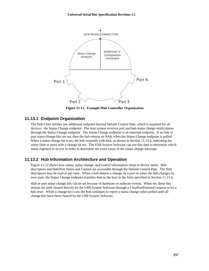
Universal Serial Bus Specification Revision 1.1
257
Port 1 Port N
Port 3Port 2
Status ChangeEndpoint
ENDPOINT 0:ConfigurationInformation
UPSTREAM CONNECTION
Figure 11-11. Example Hub Controller Organization
11.13.1 Endpoint OrganizationThe Hub Class defines one additional endpoint beyond Default Control Pipe, which is required for alldevices: the Status Change endpoint. The host system receives port and hub status change notificationsthrough the Status Change endpoint. The Status Change endpoint is an interrupt endpoint. If no hub orport status change bits are set, then the hub returns an NAK when the Status Change endpoint is polled.When a status change bit is set, the hub responds with data, as shown in Section 11.13.4, indicating theentity (hub or port) with a change bit set. The USB System Software can use this data to determine whichstatus registers to access in order to determine the exact cause of the status change interrupt.
11.13.2 Hub Information Architecture and OperationFigure 11-12 shows how status, status change, and control information relate to device states. Hubdescriptors and Hub/Port Status and Control are accessible through the Default Control Pipe. The Hubdescriptors may be read at any time. When a hub detects a change on a port or when the hub changes itsown state, the Status Change endpoint transfers data to the host in the form specified in Section 11.13.4.
Hub or port status change bits can be set because of hardware or software events. When set, these bitsremain set until cleared directly by the USB System Software through a ClearPortFeature() request or by ahub reset. While a change bit is set, the hub continues to report a status change when polled until allchange bits have been cleared by the USB System Software.

Universal Serial Bus Specification Revision 1.1
258
Status Information(static)
Change Information(due to hardware
events)
Control Information(change device state)
Hos
t S
oftw
are
(e.g
., H
ubD
river
)
Change DeviceState
Software DeviceControl
All Status
Changes
Device Control
Hardware Events
Hardware Events
Figure 11-12. Relationship of Status, Status Change, and Control Information to Device States
The USB System Software uses the interrupt pipe associated with the Status Change endpoint to detectchanges in hub and port status.

Universal Serial Bus Specification Revision 1.1
259
11.13.3 Port Change Information Processing
Hubs report a port's status through port commands on a per-port basis. The USB System Softwareacknowledges a port change by clearing the change state corresponding to the status change reported by thehub. The acknowledgment clears the change state for that port so future data transfers to the Status Changeendpoint do not report the previous event. This allows the process to repeat for further changes (see Figure11-13.)
Begin
System Software requests Interrupt Pipe notification for Status Change Information
Change DataAvailable ?
Hub NAKsstatus change
IN token
No
Yes
Interrupt Pipe returns Hub and Port Status Change Bitmap
Interrupt Pipe notification retired
System Software reads Hub or Port status (for affected ports)
System Software processes accumulated change information
Any ChangedState?
No
Yes � Accumulate change information� System Software clears
corresponding change state
Re-initialize Interrupt Pipe for Status Change endpoint
Return tobeginning
Figure 11-13. Port Status Handling Method
11.13.4 Hub and Port Status Change BitmapThe Hub and Port Status Change Bitmap, shown in Figure 11-14, indicates whether the hub or a port hasexperienced a status change. This bitmap also indicates which port(s) have had a change in status. Thehub returns this value on the Status Change endpoint. Hubs report this value in byte-increments. That is, ifa hub has six ports, it returns a byte quantity and reports a zero in the invalid port number field locations.the USB System Software is aware of the number of ports on a hub (this is reported in the hub descriptor)
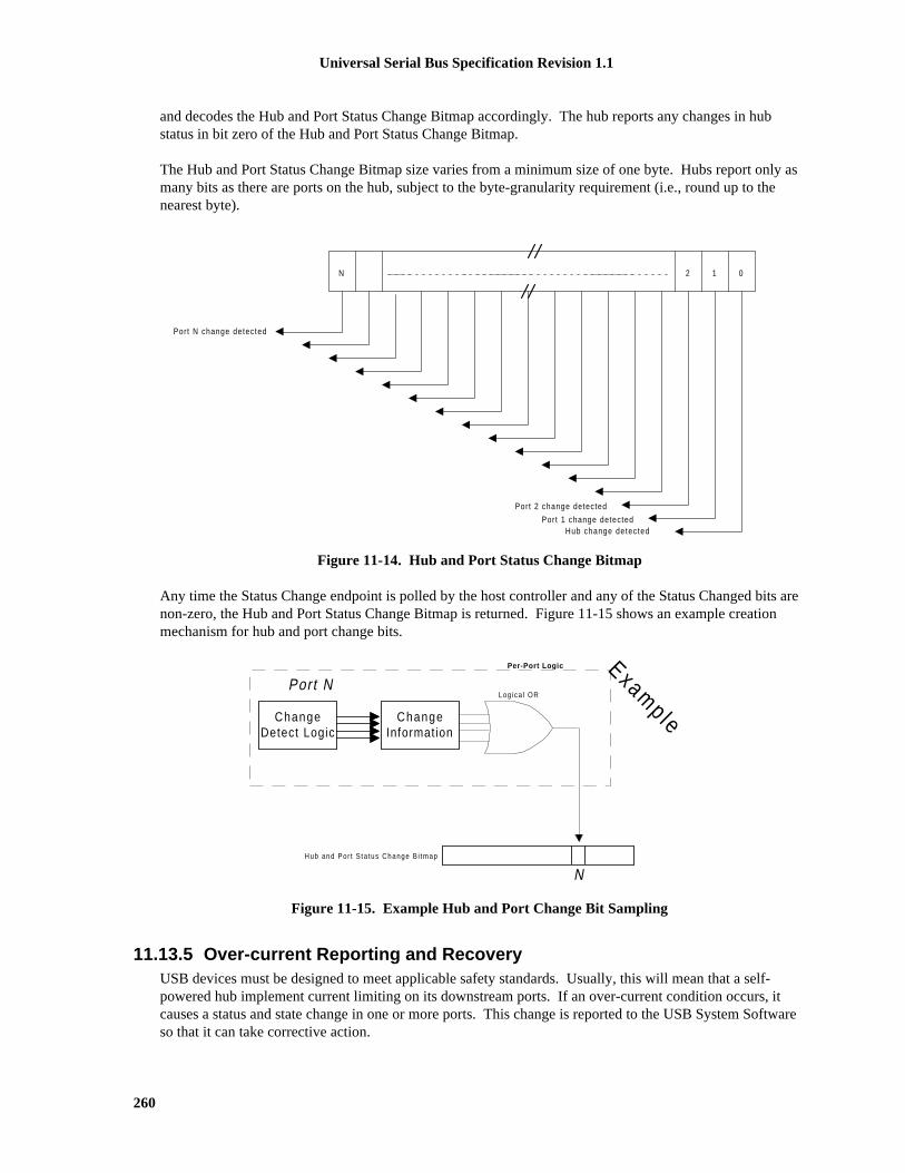
Universal Serial Bus Specification Revision 1.1
260
and decodes the Hub and Port Status Change Bitmap accordingly. The hub reports any changes in hubstatus in bit zero of the Hub and Port Status Change Bitmap.
The Hub and Port Status Change Bitmap size varies from a minimum size of one byte. Hubs report only asmany bits as there are ports on the hub, subject to the byte-granularity requirement (i.e., round up to thenearest byte).
012N
Port 1 change detectedHub change detected
Port N change detected
Port 2 change detected
Figure 11-14. Hub and Port Status Change Bitmap
Any time the Status Change endpoint is polled by the host controller and any of the Status Changed bits arenon-zero, the Hub and Port Status Change Bitmap is returned. Figure 11-15 shows an example creationmechanism for hub and port change bits.
Per-Port Lo g ic
Log ica l OR
ChangeDetect Logic
ChangeInformation
Hub and Por t S ta tus Change B i tmap
Port N
N
Example
Figure 11-15. Example Hub and Port Change Bit Sampling
11.13.5 Over-current Reporting and RecoveryUSB devices must be designed to meet applicable safety standards. Usually, this will mean that a self-powered hub implement current limiting on its downstream ports. If an over-current condition occurs, itcauses a status and state change in one or more ports. This change is reported to the USB System Softwareso that it can take corrective action.

Universal Serial Bus Specification Revision 1.1
261
A hub may be designed to report over-current as either a port or a hub event. The hub descriptor fieldwHubCharacteristics is used to indicate the reporting capabilities of a particular hub (see Section 11.15.2).The over-current status bit in the hub or port status field indicates the state of the over-current detectionwhen the status is returned. The over-current status change bit in the Hub or Port Change field indicates ifthe over-current status has changed.
When a hub experiences an over-current condition, it must place all affected ports in the Powered-off state.If a hub has per-port power switching and per-port current limiting, an over-current on one port may stillcause the power on another port to fall below specified minimums. In this case, the affected port is placedin the Powered-off state and C_PORT_OVER_CURRENT is set for the port, butPORT_OVER_CURRENT is not set. If the hub has over-current detection on a hub basis, then an over-current condition on the hub will cause all ports to enter the Powered-off state. However, in this case,neither C_PORT_OVER_CURRENT nor PORT_OVER_CURRENT is set for the affected ports.
Host recovery actions for an over-current event should include the following:
1. Host gets change notification from hub with over-current event.
2. Host extracts appropriate hub or port change information (depending on the information in thechange bitmap).
3. Host waits for over-current status bit to be cleared to 0.
4. Host cycles power on to all of the necessary ports (e.g., issues a SetPortFeature(PORT_POWER)request for each port).
5. Host re-enumerates all affected ports.
11.14 Hub ConfigurationHubs are configured through the standard USB device configuration commands. A hub that is notconfigured behaves like any other device that is not configured with respect to power requirements andaddressing. If a hub implements power switching, no power is provided to the downstream ports while thehub is not configured. Configuring a hub enables the Status Change endpoint. The USB System Softwaremay then issue commands to the hub to switch port power on and off at appropriate times.
The USB System Software examines hub descriptor information to determine the hub’s characteristics. Byexamining the hub’s characteristics, the USB System Software ensures that illegal power topologies are notallowed by not powering on the hub’s ports if doing so would violate the USB power topology. The devicestatus and configuration information can be used to determine whether the hub should be used as a bus orself-powered device. Table 11-7 summarizes the information and how it can be used to determine thecurrent power requirements of the hub.
Table 11-7. Hub Power Operating Mode Summary
Configuration Descriptor
MaxPowerbmAttributes
(Self Powered)
HubDevice Status(Self Power)
Explanation
0 0 N/A N/AThis is an illegal set of information.
0 1 0 N/AA device which is only self-powered, but doesnot have local power cannot connect to the Busand communicate.

Universal Serial Bus Specification Revision 1.1
262
Table 11-7. Hub Power Operating Mode Summary (Continued)
Configuration Descriptor
MaxPowerbmAttributes
(Self Powered)
HubDevice Status(Self Power)
Explanation
0 1 1 Self-powered only hub and local power supply isgood. Hub status also indicates local powergood, see Section 11.16.2.5. Hub functionality isvalid anywhere depth restriction is not violated.
� 0 0 N/A Bus-powered only hub. Downstream ports maynot be powered unless allowed in currenttopology. Hub device status reporting SelfPowered is meaningless in combination of azeroed bmAttributes.Self-Powered.
� 0 1 0 This hub is capable of both self- and bus-powered operating modes. It is currently onlyavailable as a bus-powered hub.
� 0 1 1 This hub is capable of both self- and bus-powered operating modes. It is currentlyavailable as a self-powered hub.
A self-powered hub has a local power supply, but may optionally draw one unit load from its upstreamconnection. This allows the interface to function when local power is not available (see Section 7.2.1.2).When local power is removed (either a hub-wide over-current condition or local supply is off), a hub ofthis type remains in the Configured state but transitions all ports (whether removable or non-removable) tothe Powered-off state. While local power is off, all port status and change information read as zero and allSetPortFeature() requests are ignored (request is treated as a no-operation). The hub will use the StatusChange endpoint to notify the USB System Software of the hub event (see Section 11.16.2.5 for details onhub status).
The MaxPower field in the configuration descriptor is used to report to the system the maximum power thehub will draw from VBUS when the configuration is selected. For bus-powered hubs, the reported valuemust not include the power for any of external downstream ports. The external devices attaching to the hubwill report their individual power requirements.
A compound device may power both the hub electronics and the permanently attached devices from VBUS.The entire load may be reported in the hubs' configuration descriptor with the permanently attacheddevices each reporting self-powered, with zero MaxPower in their respective configuration descriptors.

Universal Serial Bus Specification Revision 1.1
263
11.15 DescriptorsHub descriptors are derived from the general USB device framework. Hub descriptors define a hub deviceand the ports on that hub. The host accesses hub descriptors through the hub’s default pipe.
The USB specification (refer to Chapter 9) defines the following descriptors:
� Device
� Configuration
� Interface
� Endpoint
� String (optional).
The hub class defines additional descriptors (refer to Section 11.15.2). In addition, vendor-specificdescriptors are allowed in the USB device framework. Hubs support standard USB device commands asdefined in Chapter 9.
11.15.1 Standard DescriptorsThe hub class pre-defines certain fields in standard USB descriptors. Other fields are eitherimplementation-dependent or not applicable to this class.
Note: for the descriptors and fields shown below, the bits in a field are organized in a little-endian fashion;that is, bit location 0 is the least significant bit and bit location 7 is the most significant bit of a byte value.
Device Descriptor
bDeviceClass = HUB_CLASSCODE (09H)
bDeviceSubClass = 0
Interface Descriptor
bNumEndpoints = 1
bInterfaceClass = HUB_CLASSCODE (09H)
bInterfaceSubClass= 0
bInterfaceProtocol = 0
Configuration Descriptor
MaxPower = The maximum amount of bus power the hub will consume in thisconfiguration
Endpoint Descriptor (for Status Change Endpoint)
bEndpointAddress = Implementation-dependent; Bit 7: Direction = In(1)
wMaxPacketSize = Implementation-dependent
bmAttributes = Transfer Type = Interrupt (00000111B )
bInterval = FFH (Maximum allowable interval)
The hub class driver retrieves a device configuration from the USB System Software using theGetDescriptor() device request. The only endpoint descriptor that is returned by the GetDescriptor()request is the Status Change endpoint descriptor.

Universal Serial Bus Specification Revision 1.1
264
11.15.2 Class-specific Descriptors
11.15.2.1 Hub DescriptorTable 11-8 outlines the various fields contained by the hub descriptor.
Table 11-8. Hub Descriptor
Offset Field Size Description
0 bDescLength 1 Number of bytes in this descriptor, including this byte
1 bDescriptorType 1 Descriptor Type, value: 29H for hub descriptor
2 bNbrPorts 1 Number of downstream ports that this hub supports
3 wHubCharacteristics D1...D0: Logical Power Switching Mode00: Ganged power switching (all ports’ power at
once)01: Individual port power switching1X: Reserved. Used only on 1.0 compliant hubs
that implement no power switching.
D2: Identifies a Compound Device0: Hub is not part of a compound device1: Hub is part of a compound device
D4...D3: Over-current Protection Mode00: Global Over-current Protection. The hub
reports over-current as a summation of allports’ current draw, without a breakdown ofindividual port over-current status.
01: Individual Port Over-current Protection. Thehub reports over-current on a per-port basis.Each port has an over-current indicator.
1X: No Over-current Protection. This option is allowed only for bus-powered hubs that do notimplement over-current protection.
D15...D5: Reserved
5 bPwrOn2PwrGood 1 Time (in 2ms intervals) from the time the power-onsequence begins on a port until power is good on thatport. The USB System Software uses this value todetermine how long to wait before accessing apowered-on port.
6 bHubContrCurrent 1 Maximum current requirements of the Hub Controllerelectronics in mA.
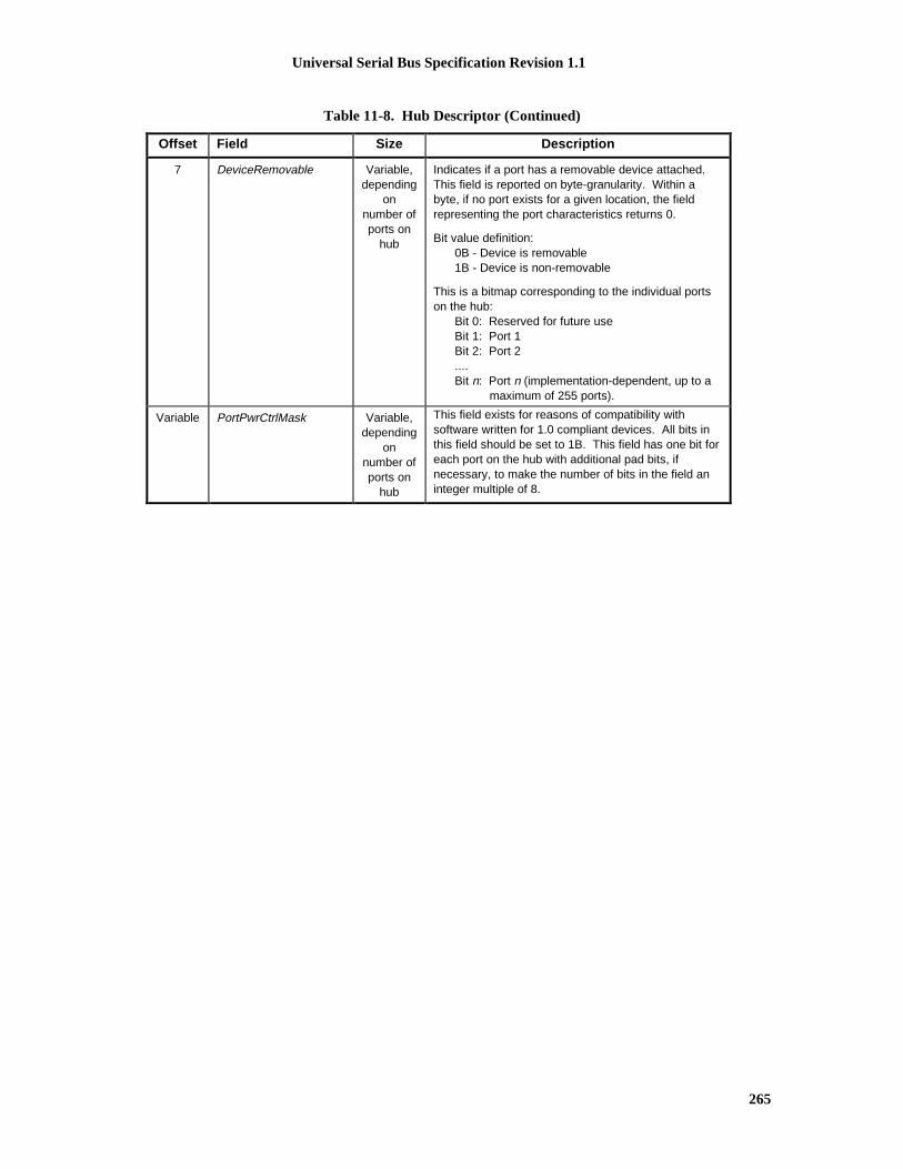
Universal Serial Bus Specification Revision 1.1
265
Table 11-8. Hub Descriptor (Continued)
Offset Field Size Description
7 DeviceRemovable Variable,depending
onnumber ofports on
hub
Indicates if a port has a removable device attached.This field is reported on byte-granularity. Within abyte, if no port exists for a given location, the fieldrepresenting the port characteristics returns 0.
Bit value definition:0B - Device is removable1B - Device is non-removable
This is a bitmap corresponding to the individual portson the hub:
Bit 0: Reserved for future useBit 1: Port 1Bit 2: Port 2....Bit n: Port n (implementation-dependent, up to a
maximum of 255 ports).
Variable PortPwrCtrlMask Variable,depending
onnumber ofports on
hub
This field exists for reasons of compatibility withsoftware written for 1.0 compliant devices. All bits inthis field should be set to 1B. This field has one bit foreach port on the hub with additional pad bits, ifnecessary, to make the number of bits in the field aninteger multiple of 8.

Universal Serial Bus Specification Revision 1.1
266
11.16 Requests
11.16.1 Standard RequestsHubs have tighter constraints on request processing timing than specified in Section 9.2.6 for standarddevices because they are crucial to the 'time to availability' of all devices attached to USB. The worst caserequest timing requirements are listed below (apply to both Standard and Hub Class requests):.
1. Completion time for requests with no data stage: 50 ms
2. Completion times for standard requests with data stage(s)Time from setup packet to first data stage: 50 msTime between each subsequent data stage: 50 msTime between last data stage and status stage: 50 ms
As hubs play such a crucial role in bus enumeration, it is recommended that hubs average response timesbe less than 5ms for all requests.
Table 11-9 outlines the various standard device requests.
Table 11-9. Hub Responses to Standard Device Requests
bRequest Hub Response
CLEAR_FEATURE Standard
GET_CONFIGURATION Standard
GET_DESCRIPTOR Standard
GET_INTERFACE Undefined. Hubs are allowed to support only one interface
GET_STATUS Standard
SET_ADDRESS Standard
SET_CONFIGURATION Standard
SET_DESCRIPTOR Optional
SET_FEATURE Standard
SET_INTERFACE Undefined. Hubs are allowed to support only one interface
SYNCH_FRAME Undefined. Hubs are not allowed to have isochronousendpoints
Optional requests that are not implemented shall return a STALL in the Data stage or Status stage of therequest.

Universal Serial Bus Specification Revision 1.1
267
11.16.2 Class-specific RequestsThe hub class defines requests to which hubs respond, as outlined in Table 11-10. Table 11-11 defines thehub class request codes. All requests in the table below except for GetBusState() and SetHubDescriptor()are mandatory.
Table 11-10. Hub Class Requests
Request bmRequestType bRequest wValue wIndex wLength Data
ClearHubFeature 00100000B CLEAR_ FEATURE FeatureSelector
Zero Zero None
ClearPortFeature 00100011B CLEAR_ FEATURE FeatureSelector
Port Zero None
GetBusState 10100011B GET_ STATE Zero Port One Per-PortBus State
GetHubDescriptor 10100000B GET_DESCRIPTOR DescriptorType andDescriptor
Index
Zero orLanguage
ID
DescriptorLength
Descriptor
GetHubStatus 10100000B GET_ STATUS Zero Zero Four HubStatus
andChange
Indicators
GetPortStatus 10100011B GET_ STATUS Zero Port Four PortStatus
andChange
Indicators
SetHubDescriptor 00100000B SET_DESCRIPTOR DescriptorType andDescriptor
Index
Zero orLanguage
ID
DescriptorLength
Descriptor
SetHubFeature 00100000B SET_ FEATURE FeatureSelector
Zero Zero None
SetPortFeature 00100011B SET_ FEATURE FeatureSelector
Port Zero None

Universal Serial Bus Specification Revision 1.1
268
Table 11-11. Hub Class Request Codes
bRequest Value
GET_ STATUS 0
CLEAR_ FEATURE 1
GET_STATE 2
SET_ FEATURE 3
Reserved for future use 4-5
GET_DESCRIPTOR 6
SET_DESCRIPTOR 7
Table 11-12 gives the valid feature selectors for the hub class. See Section 11.16.2.5 and Section 11.16.2.6 fora description of the features.
Table 11-12. Hub Class Feature Selectors
Recipient Value
C_HUB_LOCAL_POWER Hub 0
C_HUB_OVER_CURRENT Hub 1
PORT_CONNECTION Port 0
PORT_ENABLE Port 1
PORT_SUSPEND Port 2
PORT_OVER_CURRENT Port 3
PORT_RESET Port 4
PORT_POWER Port 8
PORT_LOW_SPEED Port 9
C_PORT_CONNECTION Port 16
C_PORT_ENABLE Port 17
C_PORT_SUSPEND Port 18
C_PORT_OVER_CURRENT Port 19
C_PORT_RESET Port 20

Universal Serial Bus Specification Revision 1.1
269
11.16.2.1 Clear Hub FeatureThis request resets a value reported in the hub status.
bmRequestType bRequest wValue wIndex wLength Data
00100000B CLEAR_ FEATURE FeatureSelector
Zero Zero None
Clearing a feature disables that feature; refer to Table 11-12 for the feature selector definitions that apply tothe hub as a recipient. If the feature selector is associated with a change indicator, clearing that indicatoracknowledges the change. This request format is used to clear either the C_HUB_LOCAL_POWER orC_HUB_OVER_CURRENT features.
It is a Request Error if wValue is not a feature selector listed in Table 11-12 or if wIndex or wLength are notas specified above.
If the hub is not configured, the hub's response to this request is undefined.
11.16.2.2 Clear Port FeatureThis request resets a value reported in the port status.
bmRequestType Brequest wValue wIndex wLength Data
00100011B CLEAR_ FEATURE FeatureSelector
Port Zero None
The port number must be a valid port number for that hub, greater than zero.
Clearing a feature disables that feature or starts a process associated with the feature; refer to Table 11-12for the feature selector definitions. If the feature selector is associated with a change indicator, clearingthat indicator acknowledges the change. This request format is used to clear the following features:
� PORT_ENABLE
� PORT_SUSPEND
� PORT_POWER
� C_PORT_CONNECTION
� C_PORT_RESET
� C_PORT_ENABLE
� C_PORT_SUSPEND
� C_PORT_OVER_CURRENT.
Clearing the PORT_SUSPEND feature causes a host-initiated resume on the specified port. If the port isnot in the Suspended state, the hub should treat this request as a functional no-operation.
Clearing the PORT_ENABLE feature causes the port to beplaced in the Disabled state. If the port is in thePowered-off state, the hub should treat this request as a functional no-operation.
Clearing the PORT_POWER feature causes the port to be placed in the Powered-off state and may, subjectto the constraints due to the hub’s method of power switching, result in power being removed from theport. Refer to Section 11.11 on rules for how this request is used with ports that are gang-powered.

Universal Serial Bus Specification Revision 1.1
270
It is a Request Error if wValue is not a feature selector listed in Table 11-12, if wIndex specifies a port thatdoesn't exist, or if wLength is not as specified above. It is not an error for this request to try to clear afeature that is already cleared (hub should treat as a function no-operation).
If the hub is not configured, the hub's response to this request is undefined.
11.16.2.3 Get Bus StateThis is an optional per-port diagnostic request that returns the bus state value, as sampled at the last EOF2point.
bmRequestType bRequest wValue wIndex wLength Data
10100011B GET_ STATE Zero Port One Per-Port BusState
The port number must be a valid port number for that hub, greater than zero. If an invalid port number isspecified or if wValue or wLength are not as specified above, then the hub shall return a STALL in the Datastage of the request (aborting the Status stage).
Hubs may implement an optional diagnostic aid to facilitate system debug. Hubs implement this aidthrough this optional request. This diagnostic feature provides a glimpse of the USB bus state as sampledat the last EOF2 sample point.
Hubs that implement this diagnostic feature should store the bus state at each EOF2 state in preparation fora potential request in the following USB frame.
The data returned is bitmapped in the following manner:
Bit 0: The value of the D- signal
Bit 1: The value of the D+ signal
Bits 2-7: Reserved for future use and are reset to zero.
The hub must be able to return the bus state in the Data stage transaction within the frame in which therequest was received. If the hub does not receive ACK for the data packet, the device is not required toreturn the same data packet if the host continues with the Data stage. Rather, the hub will always return thebus state at the immediately prior EOF2 sample point along with the DATA0 PID.
Hubs that do not implement this request shall return a STALL in the Data stage of the request (aborting theStatus stage).
If the hub is not configured, the hub's response to this request is undefined.

Universal Serial Bus Specification Revision 1.1
271
11.16.2.4 Get Hub DescriptorThis request returns the hub descriptor.
bmRequestType bRequest wValue wIndex wLength Data
10100000B GET_DESCRIPTOR DescriptorType andDescriptor
Index
Zero DescriptorLength
Descriptor
The GetDescriptor() request for the hub class descriptor follows the same usage model as that of thestandard GetDescriptor() request (refer to Chapter 9). The standard hub descriptor is denoted by using thevalue bDescriptorType defined in Section 11.15.2.1. All hubs are required to implement one hubdescriptor, with descriptor index zero.
If wLength is larger than the actual length of the descriptor, then only the actual length is returned. IfwLength is less than the actual length of the descriptor, then only the first wLength bytes of the descriptorare returned; this is not considered an error even if wLength is zero.
It is a Request Error if wValue or wIndex are other than as specified above.
If the hub is not configured, the hub's response to this request is undefined.
11.16.2.5 Get Hub StatusThis request returns the current hub status and the states that have changed since the previousacknowledgment.
bmRequestType bRequest wValue wIndex wLength Data
10100000B GET_ STATUS Zero Zero Four Hub Statusand Change
Indicators
The first word of data contains wHubStatus (refer to Table 11-13). The second word of data containswHubChange (refer to Table 11-14).
It is a Request Error if wValue, wIndex, or wLength are other than as specified above.
If the hub is not configured, the hub's response to this request is undefined.

Universal Serial Bus Specification Revision 1.1
272
Table 11-13. Hub Status Field, wHubStatus
Bit Description
0 Local Power Source: This is the source of the local power supply.
This field indicates whether hub power (for other than the SIE) is being provided by an external source orfrom the USB. . This field allows the USB System Software to determine the amount of power available froma hub to downstream devices.
0 = Local power supply good1 = Local power supply lost (inactive)
1 Over-current Indicator:
If the hub supports over-current reporting on a hub basis, this field indicates that the sum of all the ports’current has exceeded the specified maximum and all ports have been places in the Powered-off state. If thehub reports over-current on a per-port basis or has no over-current detection capabilities, this field is alwayszero. For more details on over-current protection, see Section 7.2.1.2.1.
0 = No over-current condition currently exists1 = A hub over-current condition exists
2-15 Reserved
These bits return 0 when read.
There are no defined feature selector values for these status bits and they can neither be set nor cleared bythe USB System Software.
Table 11-14. Hub Change Field, wHubChange
Bit Description
0 Local Power Status Change: (C_HUB_LOCAL_POWER) This field indicates that a change hasoccurred in the hub’s Local Power Source field in wHubStatus.
This field is initialized to zero when the hub receives a bus reset.0 = No change has occurred to Local Power Status1 = Local Power Status has changed
1 Over-Current Indicator Change : (C_HUB_OVER_CURRENT) This field indicates if a change hasoccurred in the Over-Current field in wHubStatus.
This field is initialized to zero when the hub receives a bus reset.
0 = No change has occurred to the Over-Current Indicator1 = Over-Current Indicator has changed
2-15 Reserved
These bits return 0 when read.
Hubs may allow setting of these change bits with SetHubFeature() requests in order to support diagnostics.If the hub does not support setting of these bits, it should either treat the SetHubFeature() request as aRequest Error or as a functional no-operation. When set, these bits may be cleared by a ClearHubFeature()request. A request to set a feature that is already set or to clear a feature that is already clear has no effectand the hub will not fail the request.

Universal Serial Bus Specification Revision 1.1
273
11.16.2.6 Get Port StatusThis request returns the current port status and the current value of the port status change bits.
bmRequestType BRequest wValue wIndex wLength Data
10100011B GET_STATUS Zero Port Four Port Statusand Change
Indicators
The port number must be a valid port number for that hub, greater than zero.
The first word of data contains wPortStatus (refer to Table 11-15). The second word of data containswPortChange (refer to Table 11-14).
The bit locations in the wPortStatus and wPortChange fields correspond in a one-to-one fashion whereapplicable.
It is a Request Error if wValue or wLength are other than as specified above or if wIndex specifies a portthat does not exist.
If the hub is not configured, the behavior of the hub in response to this request is undefined.
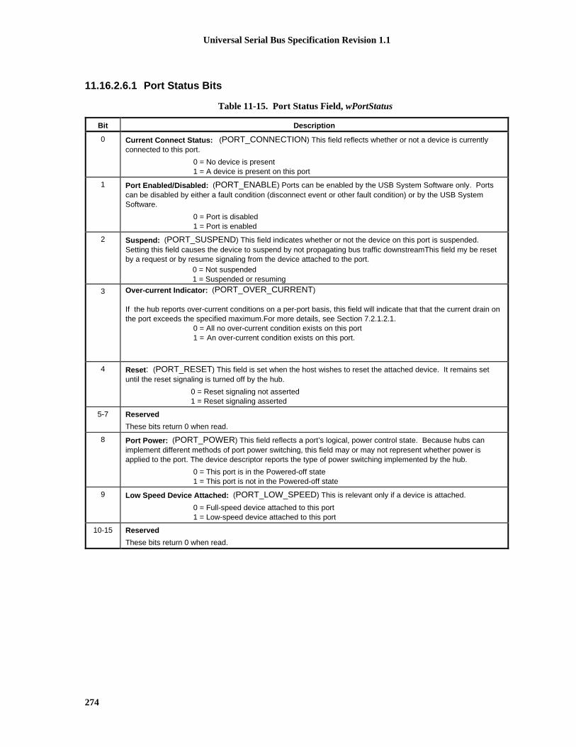
Universal Serial Bus Specification Revision 1.1
274
11.16.2.6.1 Port Status Bits
Table 11-15. Port Status Field, wPortStatus
Bit Description
0 Current Connect Status: (PORT_CONNECTION) This field reflects whether or not a device is currentlyconnected to this port.
0 = No device is present1 = A device is present on this port
1 Port Enabled/Disabled: (PORT_ENABLE) Ports can be enabled by the USB System Software only. Portscan be disabled by either a fault condition (disconnect event or other fault condition) or by the USB SystemSoftware.
0 = Port is disabled1 = Port is enabled
2 Suspend: (PORT_SUSPEND) This field indicates whether or not the device on this port is suspended.Setting this field causes the device to suspend by not propagating bus traffic downstreamThis field my be resetby a request or by resume signaling from the device attached to the port.
0 = Not suspended1 = Suspended or resuming
3 Over-current Indicator: (PORT_OVER_CURRENT)
If the hub reports over-current conditions on a per-port basis, this field will indicate that that the current drain onthe port exceeds the specified maximum.For more details, see Section 7.2.1.2.1.
0 = All no over-current condition exists on this port1 = An over-current condition exists on this port.
4 Reset : (PORT_RESET) This field is set when the host wishes to reset the attached device. It remains setuntil the reset signaling is turned off by the hub.
0 = Reset signaling not asserted1 = Reset signaling asserted
5-7 Reserved
These bits return 0 when read.
8 Port Power: (PORT_POWER) This field reflects a port’s logical, power control state. Because hubs canimplement different methods of port power switching, this field may or may not represent whether power isapplied to the port. The device descriptor reports the type of power switching implemented by the hub.
0 = This port is in the Powered-off state1 = This port is not in the Powered-off state
9 Low Speed Device Attached: (PORT_LOW_SPEED) This is relevant only if a device is attached.
0 = Full-speed device attached to this port1 = Low-speed device attached to this port
10-15 Reserved
These bits return 0 when read.

Universal Serial Bus Specification Revision 1.1
275
11.16.2.6.1.1 PORT_CONNECTIONWhen the Port Power bit is one, this bit indicates whether or not a device is attached. This field reads asone when a device is attached; it reads as zero when no device is attached. This bit is reset to zero whenthe port is in the Powered-off state or the Disconnected states. It is set to one when the port is in thePowered state, a device attach is detected (see Section 7.1.7.1) and the port transitions from theDisconnected state to the Disabled state.
SetPortFeature(PORT_CONNECTION) and ClearPortFeature(PORT_CONNECTION) requests shall notbe used by the USB System Software and must be treated as no-operation requests by hubs.
11.16.2.6.1.2 PORT_ENABLEThis bit is set when the port is allowed to send or receive packet data or resume signaling.
This bit may be set only as a result of a SetPortFeature(PORT_RESET) request. When the hub exits theResetting state or, if present, the Speed_eval state, this bit is set and bus traffic may be transmitted to theport. This bit may be cleared as the result of any of the following:
� The port being in the Powered-off state
� Receipt of a ClearPortFeature(PORT_ENABLE) request
� Port_Error detection
� Disconnect detection
� When the port enters the Resetting state as a result of receiving the SetPortFeature(PORT_RESET)request.
The hub response to a SetPortFeature(PORT_ENABLE) request is not specified. The preferred behavior isthat the hub respond with a Request Error. This may not be used by the USB System Software. TheClearPortFeature(PORT_ENABLE) request is supported as specified in Section 11.5.1.4.
11.16.2.6.1.3 PORT_SUSPENDThis bit is set to one when the port is selectively suspended by the USB System Software. While this bit isset, the hub does not propagate downstream-directed traffic to this port, but the hub will respond to resumesignaling from the port. This bit can be set only if the port’s PORT_ENABLE bit is set and the hubreceives a SetPortFeature(PORT_SUSPEND) request. This bit is cleared to zero on the transition from theSendEOP state to the Enabled state, or on the transition from the Restart_S state to the Transmit state, or onany event that causes the PORT_ENABLE bit to be cleared while the PORT_SUSPEND bit is set.
The SetPortFeature(PORT_SUSPEND) request may be issued by the USB System Software at any time butwill have an effect only as specified in Section 11.5.
11.16.2.6.1.4 PORT_OVER-CURRENTThis bit is set to one while an over-current condition exists on the port. This bit is cleared when an over-current condition does not exist on the port.
If the voltage on this port is affected by an over-current condition on another port then this bit is set andremains set until the over-current condition on the affecting port is removed. When the over-currentcondition on the affecting port is removed, this bit is reset to zero if an over-current condition does notexist on this port.
Over-current protection is required on self-powered hubs (it is optional on bus-powered hubs) as outlinedin Section 7.2.1.2.1.
Universal Serial Bus Specification Revision 1.1
276
The SetPortFeature(PORT_OVER_CURRENT) and ClearPortFeature(PORT_OVER_CURRENT)requests shall not be used by the USB System Software and may be treated as no-operation requests byhubs.
11.16.2.6.1.5 PORT_RESETThis bit is set while the port is in the Resetting state. A SetPortFeature(PORT_RESET) request will initiatethe Resetting state if the conditions in Section 11.5.1.5 are met. This bit is set to zero while the port is inthe Powered-off state.
The ClearPortFeature(PORT_RESET) request shall not be used by the USB System Software and may betreated as a no-operation request by hubs.
11.16.2.6.1.6 PORT_POWERThis bit reflects the current power state of a port. This bit is implemented on all ports whether or not actualport power switching devices are present.
While this bit is zero, the port is in the Powered-off state. Similarly, anything that causes this port to go tothe Power-off state will cause this bit to be set to zero.
A SetPortFeature(PORT_POWER) will set this bit to one unless both C_HUB_LOCAL_POWER andLocal Power Status (in wHubStatus) are set to one in which case the request is treated as a functional no-operation.
This bit may be cleared under the following curcumstances:
� Hub receives a ClearPortFeature(PORT_POWER).
� An over-current condition exists on the port.
� An over-current condition on another port causes the power on this port to be shut off.
The SetPortFeature(PORT_POWER) and ClearPortFeature(PORT_POWER) requests may be issued by theUSB System Software whenever the port is not in the Not Configured state, but will have an effect only asspecified in Section 11.11.
11.16.2.6.1.7 PORT_LOW_SPEEDThis bit has meaning only when the PORT_ENABLE bit is set. This bit is set to one if the attached deviceis low-speed.
The SetPortFeature(PORT_LOW_SPEED) and ClearPortFeature(PORT_LOW_SPEED) requests shall notbe used by the USB System Software and may be treated as no-operation requests by hubs.

Universal Serial Bus Specification Revision 1.1
277
11.16.2.6.2 Port Status Change BitsPort status change bits are used to indicate changes in port status bits that are not the direct result ofrequests. Port status change bits can be cleared with a ClearPortFeature() request or by a hub reset. Hubsmay allow setting of the status change bits with a SetPortFeature() request for diagnostic purposes. If ahub does not support setting of the status change bits, it may either treat the request as a Request Error or asa functional no-operation. Table 11-16 describes the various bits in the wPortChange field.
Table 11-16. Port Change Field, wPortChange
Bit Description
0 Connect Status Change: (C_PORT_CONNECTION) Indicates a change has occurred in the port’s CurrentConnect Status. The hub device sets this field as described in Section 11.16.2.6.2.1.
0 = No change has occurred to Current Connect status1 = Current Connect status has changed
1 Port Enable/Disable Change: (C_PORT_ENABLE) This field is set to one when a port is disabled becauseof a Port_Error condition (see Section 11.8.1).
2 Suspend Change: (C_PORT_SUSPEND) This field indicates a change in the host-visible suspend state ofthe attached device. It indicates the device has transitioned out of the Suspend stateThis field is set only whenthe entire resume process has completed. That is, the hub has ceased signaling resume on this port.
0 = No change1 = Resume complete
3 Over-Current Indicator Change: (C_PORT_OVER_CURRENT) This field applies only to hubs that reportover-current conditions on a per-port basis (as reported in the hub descriptor).
0 = No change has occurred to Over-Current Indicator1 = Over-Current Indicator has changed
If the hub does not report over-current on a per-port basis, then this field is always zero.
4 Reset Change: (C_PORT_RESET) This field is set when reset processing on this port is complete.
0 = No change1 = Reset complete
5-15 Reserved
These bits return 0 when read.
11.16.2.6.2.1 C_PORT_CONNECTIONThis bit is set when the PORT_CONNECTION bit changes because of an attach or detach detect event (seeSection 7.1.7.1). This bit will be cleared to zero by a ClearPortFeature(C_PORT_CONNECTION) requestor while the port is in the Powered-off state.
11.16.2.6.2.2 C_PORT_ENABLE.This bit is set when the PORT_ENABLE bit changes from one to zero as a result of a Port Error condition(see Section 11.8.1.). This bit is not set on any other changes to PORT_ENABLE.
This bit may be set if, on a SetPortFeature(PORT_RESET) the port stays in the Disabled state because aninvalid idle state exists on the bus (see Section 11.8.2).
This bit will be cleared by a ClearPortFeature(C_PORT_ENABLE) request or while the port is in thePowered-off state.

Universal Serial Bus Specification Revision 1.1
278
11.16.2.6.2.3 C_PORT_SUSPENDThis bit is set on the following transitions:
� on transition from the Resuming state to the SendEOP state
� on transition from the Restart_S state to the Transmit state.
This bit will be cleared by a ClearPortFeature(C_PORT_SUSPEND) request, or while the port is in thePowered-off state.
11.16.2.6.2.4 C_PORT_OVER-CURRENTThis bit is set when the PORT_OVER_CURRENT bit changes from zero to one or from one to zero. Thisbit is also set if the port is placed in the Powered-off state due to an over-current condition on another port.
This bit will be cleared when the port is in the Not Configured state or by aClearPortFeature(C_PORT_OVER-CURRENT) request.
11.16.2.6.2.5 C_PORT_RESETThis bit is set when the port transitions from the Resetting state (or, if present, the Speed_eval state) to theEnabled state.
This bit will be cleared by a ClearPortFeature(C_PORT_RESET) request, or while the port is in thePowered-off state.
11.16.2.7 Set Hub DescriptorThis request overwrites the hub descriptor.
bmRequestType bRequest wValue wIndex wLength Data
00100000B SET_DESCRIPTOR DescriptorType andDescriptor
Index
Zero DescriptorLength
Descriptor
The SetDescriptor request for the hub class descriptor follows the same usage model as that of the standardSetDescriptor request (refer to Chapter 9). The standard hub descriptor is denoted by using the valuebDescriptorType defined in Section 11.15.2.1. All hubs are required to implement one hub descriptor,with descriptor index zero.
This request is optional. This request writes data to a class-specific descriptor. The host provides the datathat is to be transferred to the hub during the data transfer phase of the control transaction. This requestwrites the entire hub descriptor at once.
Hubs must buffer all the bytes received from this request to ensure that the entire descriptor has beensuccessfully transmitted from the host. Upon successful completion of the bus transfer, the hub updates thecontents of the specified descriptor.
It is a Request Error if wIndex is not zero or if wLength does not match the amount of data sent by the host.Hubs that do not support this request respond with a STALL during the Data stage of the request.
If the hub is not configured, the hub's response to this request is undefined.

Universal Serial Bus Specification Revision 1.1
279
11.16.2.8 Set Hub FeatureThis request sets a value reported in the hub status.
bmRequestType bRequest wValue wIndex wLength Data
00100000B SET_ FEATURE FeatureSelector
Zero Zero None
Setting a feature enables that feature; refer to Table 11-12for the feature selector definitions that apply tothe hub as recipient. Change indicators may not be acknowledged using this request.
It is a Request Error if wValue is not a feature selector listed in Table 11-12 or if wIndex or wLength are notas specified above.
If the hub is not configured, the hub's response to this request is undefined.
11.16.2.9 Set Port FeatureThis request sets a value reported in the port status.
bmRequestType bRequest wValue wIndex wLength Data
00100011B SET_ FEATURE FeatureSelector
Port Zero None
The port number must be a valid port number for that hub, greater than zero.
Setting a feature enables that feature or starts a process associated with that feature; see Table 11-12 for thefeature selector definitions that apply to a port as a recipient. Change indicators may not be acknowledgedusing this request. Features that can be set with this request are:
� PORT_RESET
� PORT_SUSPEND
� PORT_POWER
� C_PORT_CONNECTION*
� C_PORT_RESET*
� C_PORT_ENABLE*
� C_PORT_SUSPEND*
� C_PORT_OVER_CURRENT*.
*denotes features that are not required to be set by this request.
Setting the PORT_SUSPEND feature causes bus traffic to cease on that port and, consequently, the deviceto suspend. Setting the reset feature PORT_RESET causes the hub to signal reset on that port. When thereset signaling is complete, the hub sets the C_PORT_RESET change indicator and immediately enablesthe port. Refer to Section 11.10 for a complete discussion of host-initiated reset behavior. Also seeSection 11.16.2.6.1 for further details.
The hub must meet the following requirements:
Universal Serial Bus Specification Revision 1.1
280
� If the port is in the Powered-off state, the hub must treat a SetPortFeature(PORT_RESET) request as afunctional no-operation.
� If the port is not in the Enabled or Transmitting state, the hub must treat aSetPortFeature(PORT_SUSPEND) request as a functional no-operation.
� If the port is not in the Powered-off state, the hub must treat a SetPortFeature(PORT_POWER) requestas a functional no-operation.
It is a Request Error if wValue is not a feature selector listed in Table 11-12, if wIndex specifies a port thatdoen't exist, or if wLength is not as specified above.
If the hub is not configured, the hub's response to this request is undefined.

Universal Serial Bus Specification Revision 1.1
281
Index
4X over-sampling state machine DPLLs, 7.1.15
Aabnormal termination sequences, 11.3.3aborting/retiring transfers
aborting control transfers, 5.5.5client role in, 10.5.2.2conditions for, 5.3.2message pipes and, 5.3.2.2packet size and, 5.5.3USBDI role, 10.5.3.2.1
access frequency of control pipes, 5.5.4Acknowledge packet. See ACKsACKs, 8.3.1 Table 8-1
in bulk transfers, 8.5.1in control transfers, 8.5.2, 8.5.2.1corrupted ACK handshake, 8.5.2.3, 8.6.4in data toggle, 8.6, 8.6.1, 8.6.2defined, 2.0 glossaryfunction response to OUT transactions, 8.4.5.3host response to IN transactions, 8.4.5.2overview, 8.4.4in request processing, 9.2.6
A connectors. See Series "A" and "B" connectorsactive devices, defined, 2.0 glossaryactive pipes, 10.5.2.2Active state (transmitter state machine), 11.6.2,
11.6.2.2adaptive endpoints
connection requirements, 5.10.4.3feedback for isochronous transfers, 5.10.4.2overview, 5.10.4.1.3
adding devices. See dynamic insertion and removalAddress device state
bus enumeration process, 9.1.2overview, 9.1.1.4standard device requests, 9.4.1:9.4.11visible device state table, 9.1.1 Table 9-1
addressesAddress device state, 9.1.1 Table 9-1, 9.1.1.4,
9.1.2, 9.4.1:9.4.11aliasing, 8.3.2assignment
after dynamic insertion or removal, 4.6.3bus enumeration, 2.0 glossary, 4.6.3, 9.1.2device initialization, 10.5.1.1operations overview, 9.2.2re-enumerating sub-trees, 10.5.4.6staged power switching in functions and, 7.2.1.4time limits for completing, 9.2.6.3USB System Software role, 4.9
endpoint addresses, 5.3.1, 9.6.4SetAddress() request, 9.4.6
address fieldsaddress field (ADDR), 8.3.2.1, 8.3.5.1, 8.4.1endpoint field (ENDP), 8.3.2.2, 8.3.5.1, 8.4.1packet address fields, 8.3.2:8.3.2.2
ADDR fieldoverview, 8.3.2.1token CRCs, 8.3.5.1in token packets, 8.4.1
aging, data-rate inaccuracies and, 7.1.11aliasing addresses, 8.3.2allocating bit times in handshake packets, 11.3.3allocating buffers. See buffersallocating USB bandwidth
transfer management, 5.9.1:5.9.1.5USB System role, 10.3.2
alternate settings for interfacesconfiguration requirements, 10.3.1GetInterface() request, 9.4.4in interface descriptors, 9.6.3SetInterface() request, 9.4.10USBDI mechanisms, 10.5.2.10USB support for, 9.2.3
American National Standard/Electronic IndustriesAssociation, 6.7.1
American Standard Test Materials, 6.7.1ANSI/EIA-364-C (12/94), 6.7.1applications
in source-to-sink connectivity, 5.10.4.3USB suitability for, 3.3
application space taxonomy, 3.2architectural overview of USB
architectural extensions, 4.10bus protocol, 4.4bus topology, 4.1.1data flow types, 4.7, 4.7:4.7.5hub architecture, 4.8.2.1, 11.1.1, 11.13.2mechanical and electrical specifications, 4.2:4.2.2,
6.1physical interface, 4.2, 4.2:4.2.2power, 4.3, 4.3:4.3.2robustness and error handling, 4.5, 4.5:4.5.2system configuration, 4.6, 4.6:4.6.3USB devices, 4.1.1.2, 4.8, 4.8:4.8.2.2USB host, 4.1.1.1, 4.9USB system description, 4.1, 4.1:4.1.1.2
assigning addresses. See addresses; busenumeration
ASTM-D-4565, 6.6.3, 6.7.1ASTM-D-4566, 6.6.3, 6.7.1asynchronous data transfers, 2.0 glossary, 4.9asynchronous endpoints
connection requirements, 5.10.4.3feedback for isochronous transfers, 5.10.4.2overview, 5.10.4.1.1
asynchronous RA, 2.0 glossary, 5.10.4.3. See alsoRA (rate adaptation)
asynchronous SRC, 2.0 glossary. See also SRCAttached device state
in bus enumeration process, 9.1.2overview, 9.1.1.1visible device state table, 9.1.1 Table 9-1
attaching devices. See dynamic insertion and removal

Universal Serial Bus Specification Revision 1.1
282
attenuation, 7.1.17attributes of devices in configuration descriptors, 9.6.2attributes of endpoints in endpoint descriptors, 9.6.4audio connectivity, 5.10.4.3.1Audio Device Class Specification Revision 1.0, 9.6audio devices, defined, 2.0 glossaryavailable time in frames
bulk transfers and, 5.8.4bus bandwidth reclamation, 5.9.5control transfers and, 5.5.4interrupt transfer bus access constraints, 5.7.4isochronous transfers and, 5.6, 5.6.4
AWG, 2.0 glossary, 6.6.2
Bbabble
defined, 2.0 glossaryEOF2 timing points and, 11.2.2error detection and recovery, 8.7.4
background of USB development, 3.1:3.3bAlternateSetting field (interface descriptors), 9.6.3bandwidth
allocating for pipes, 4.4, 4.7.5bandwidth reclamation, 5.9.5defined, 2.0 glossarytransfer management, 4.7.5, 5.9.1:5.9.1.5, 10.3.2USB system role in, 10.3.2
battery-powered hubs, 7.2.1bcdDevice field (device descriptors), 9.6.1bcdUSB field (device descriptors), 9.6.1bConfigurationValue field (configuration descriptors),
9.6.2B connectors. See Series "A" and "B" connectorsbDescLength field (hub descriptors), 11.15.2.1bDescriptorType field
configuration descriptors, 9.6.2device descriptors, 9.6.1endpoint descriptors, 9.6.4hub descriptors, 11.15.2.1, 11.16.2.4, 11.16.2.7interface descriptors, 9.6.3string descriptors, 9.6.5
bDeviceClass field, 9.6.1, 11.15.1bDeviceProtocol field (device descriptors), 9.6.1bDeviceSubClass field, 9.6.1, 11.15.1bEndpointAddress field, 9.6.4, 11.15.1bHubContrCurrent field (hub descriptors), 11.15.2.1bi-directional communication flow, 5.6.2, 5.8.2big endian, defined, 2.0 glossarybInterfaceClass field, 9.6.3, 11.15.1bInterfaceNumber field (interface descriptors), 9.6.3bInterfaceProtocol field, 9.6.3, 11.15.1bInterfaceSubClass field, 9.6.3, 11.15.1bInterval field, 9.6.4, 11.15.1bit cells, decoding, 7.1.15bitmaps of hub and port status changes, 11.13.4bit ordering, 8.1bits, defined, 2.0 glossarybit stuffing
bit stuff violations, 8.7.1calculating transaction times, 5.9.3defined, 2.0 glossaryoverview, 7.1.9
bit timesbit time designations, 11.3bit time zero, 11.3in transaction completion prediction, 11.3.3
bLength fieldconfiguration descriptors, 9.6.2device descriptors, 9.6.1endpoint descriptors, 9.6.4interface descriptors, 9.6.3string descriptors, 9.6.5
blocking packets in Collision conditions, 11.8.3blunt cut termination, 6.4.2, 6.4.3bmAttributes field
configuration descriptors, 9.6.2endpoint descriptors, 9.6.4hub descriptors, 11.14, 11.15.1
bMaxPacketSize0 field (device descriptors), 9.6.1bmRequestType field
hub class requests, 11.16.2overview, 9.3.1Setup data format, 9.3standard device requests, 9.4
bNbrPorts field (hub descriptors), 11.15.2.1bNumConfigurations field (device descriptors), 9.6.1bNumEndpoints field, 9.6.3, 11.15.1bNumInterfaces field (configuration descriptors), 9.6.2bPwrOn2PwrGood field, 11.11, 11.15.2.1bRequest field
hub class requests, 11.16.2overview, 9.3.2Setup data format, 9.3standard device requests, 9.4standard hub requests, 11.16.1
broadcast mode of hub operation, 11.1.2.1B/S or b/S, defined, 2.0 glossarybString field (string descriptors), 9.6.5buffers
buffer impedance, 7.1.1.1calculating sizes in functions and software, 5.9.4client pipes and, 10.5.1.2.2client role in, 10.3.3, 10.5.3defined, 2.0 glossaryendpoint buffer size, 4.4hub I/O buffer requirements, 11.12:11.12.2identifying location and length, 10.3.4interrupt transfers and, 5.7.3isochronous transfers and, 5.10.4.2non-USB isochronous application, 5.10.1packet buffers, 2.0 glossaryprebuffering data, 5.10.5rate matching and, 5.10.8rise and fall times for full-speed buffers, 7.1.2USBD role in allocating, 10.5.1.2.1
bulk transfersbus access constraints, 5.8.4data format, 5.8.1data sequences, 5.8.5defined, 2.0 glossary, 5.4direction, 5.8.2overview, 4.7.2, 5.8packet size, 5.8.3, 9.6.4transaction format, 8.5.1

Universal Serial Bus Specification Revision 1.1
283
bulk transfers (continued)transaction organization within IRPs, 5.9.2USBD pipe mechanism responsibilities, 10.5.3.1.3
bus access for transfersbulk transfer constraints, 5.8.4bus bandwidth reclamation, 5.9.5calculating buffer sizes, 5.9.4calculating bus transaction times, 5.9.3client software role in, 5.9.1.1control transfer constraints, 5.5.4HCD role in, 5.9.1.3Host Controller role in, 5.9.1.5interrupt transfer constraints, 5.7.4isochronous transfer constraints, 5.6.4transaction list, 5.9.1.4transaction tracking, 5.9.2transfer management, 5.9.1:5.9.1.5transfer type overview, 5.4USBD role in, 5.9.1.2
bus clock, 5.10.2, 5.10.3, 5.10.8bus enumeration
defined, 2.0 glossarydevice initialization, 10.5.1.1overview, 4.6.3, 9.1.2re-enumerating sub-trees, 10.5.4.6staged power switching in functions, 7.2.1.4USB System Software role, 4.9
Bus Management services, 10.5.4.2bus-powered devices and functions
configuration descriptors, 9.6.2defined, 4.3.1device states, 9.1.1.2high-power bus-powered functions, 7.2.1.4low-power bus-powered functions, 7.2.1.3power budgeting, 9.2.5.1
bus-powered hubsconfiguration, 11.14defined, 4.3.1, 7.2.1device states, 9.1.1.2overview, 7.2.1.1power switching, 11.11voltage drop budget, 7.2.2
bus protocol overview, 4.4Bus_Reset receiver state, 11.6.1, 11.6.1.6bus states
detecting, 11.16.2.3evaluating after reset, 7.1.7.1global suspend, 7.1.7.4.1Host Controller role in state handling, 10.2.1signaling levels and, 7.1.7
bus timing/electrical characteristics, 7.3.2bus topology, 5.2:5.2.5
client-software-to-function relationship, 5.2.5defined, 4.1devices, 5.2.2hosts, 5.2.1illustrated, 4.1.1logical bus topology, 5.2.4physical bus topology, 5.2.3
bus transaction timeout in isochronous transfers,5.10.7
bus turn-around time, 2.0 glossary, 7.1.18, 8.7.2
bypass capacitors, 7.2.4.1, 7.2.4.2bytes, defined, 2.0 glossary
Ccable assemblies, 6.4:6.4.4cable attenuation, 7.1.17cable delay
electrical characteristics, 7.3.2 Table 7-9full-speed cables, 6.4.2hub differential delay, differential jitter, and SOP
distortion, 7.3.3 Figure 7-42hub EOP delay and EOP skew, 7.3.3 Figure 7-43hub signaling timings, 7.1.14inter-packet delay and, 7.1.18low-speed cables, 6.4.3, 7.1.1.2overview, 7.1.16propagation delay, 6.4.1, 6.7 Table 6-7, 7.1.1.2skew delay, 6.7 Table 6-7, 7.1.3, 7.3.3 Figure 7-43
cablesattenuation, 7.1.17cable assemblies, 6.4:6.4.4cable delay (See cable delay)captive cables
full-speed captive cable assemblies, 6.4.2inter-packet delay and, 7.1.18low-speed captive cable assemblies, 6.4.3maximum capacitance, 7.1.6termination, 7.1.5
color choices, 6.4construction, 6.6.2description, 6.6.1detachable cables
cable delay, 7.1.16connectors and, 6.2detachable cable assemblies, 6.4.1inter-packet delay and, 7.1.18low-speed detachable cables, 6.4.4maximum capacitance, 7.1.6termination, 7.1.5voltage drop budget, 7.2.2
electrical characteristics and standards, 4.2.1,6.6.3, 6.7, 7.3.2 Table 7-9
end-to-end signal delay, 7.1.19environmental characteristics, 6.6.4, 6.7flyback voltage, 7.2.4.2full-speed cables, 6.4.2impedance, 6.4.1, 6.4.2, 6.7 Table 6-7input capacitance, 7.1.6length, 6.4.1, 6.4.2, 6.4.3listing, 6.6.5low-speed cables, 6.4.3, 6.4.4mechanical configuration and material
requirements, 6.6:6.6.5, 6.7overview, 6.3prohibited cable assemblies, 6.4.4pull-out standards, 6.7 Table 6-7shielding, 6.6, 6.6.1termination, 7.1.5voltage drop budget, 7.2.2

Universal Serial Bus Specification Revision 1.1
284
calculationsbuffering for rate matching, 5.10.8buffer sizes in functions and software, 5.9.4bus transaction times, 5.9.3
capabilities, defined, 2.0 glossarycapacitance
after dynamic attach, 7.2.4.1decoupling capacitance, 7.3.2 Table 7-5input capacitance, 7.1.6, 7.3.2 Table 7-5low-speed buffers, 7.1.1.2, 7.1.2low-speed cable capacitive loads, 6.4.3optional edge rate control capacitors, 7.1.6pull-up resistors and, 7.1.5single-ended capacitance, 7.1.1.2small capacitors, 7.1.6target maximum droop and, 7.2.4.1unmated contact capacitance, 7.3.2 Table 7-9
capacitive load, 6.7 Table 6-7captive cables
full-speed captive cable assemblies, 6.4.2inter-packet delay and, 7.1.18low-speed captive cable assemblies, 6.4.3maximum capacitance, 7.1.6termination, 7.1.5
change bitsdevice states, 11.13.2hub and port status change bitmap, 11.13.4hub status, 11.16.2.5over-current status change bits, 11.13.5port status change bits, 11.16.2.6.2:11.16.2.6.2.5Status Change endpoint defined, 11.13.1
change propagation, host state handling of, 10.2.1characteristics of devices, 2.0 glossary, 9.6.2C_HUB_LOCAL_POWER, 11.11, 11.16.2, 11.16.2.1,
11.16.2.5, 11.16.2.6.1.6C_HUB_OVER_CURRENT, 11.16.2, 11.16.2.1C_HUB_OVER_POWER, 11.16.2.5classes of devices. See device classesClass field, 9.2.3, 9.6.3class-specific descriptors, 9.5, 11.15.2.1class-specific requests
hub class-specific requests, 11.16.2:11.16.2.9time limits for completing, 9.2.6.5USBDI mechanisms, 10.5.2.8
ClearFeature() request, CLEAR_FEATUREClearHubFeature() request, 11.16.2.1ClearPortFeature() request, 11.16.2.2endpoint status and, 9.4.5hub class requests, 11.16.2hub requests, 11.16.1overview, 9.4.1standard device request codes, 9.4
ClearHubFeature() requestclearing hub features, 11.16.2.5hub class requests, 11.16.2hub class-specific requests, 11.16.2.1
clearing pipes, 10.5.2.2ClearPortFeature() request
clearing status change bits, 11.13.2, 11.16.2.6.2C_PORT_CONNECTION, 11.16.2.6.2.1C_PORT_ENABLE, 11.16.2.6.2.2C_PORT_OVER-CURRENT, 11.16.2.6.2.4
ClearPortFeature() request (continued)C_PORT_RESET, 11.16.2.6.2.5C_PORT_SUSPEND, 11.16.2.6.2.3hub class requests, 11.16.2, 11.16.2.2PORT_CONNECTION, 11.16.2.6.1.1PORT_ENABLE, 11.5.1.4, 11.16.2.6.1.2PORT_LOW_SPEED, 11.16.2.6.1.7PORT_OVER_CURRENT, 11.16.2.6.1.4PORT_POWER, 11.5.1.2, 11.16.2.6.1.6PORT_RESET, 11.16.2.6.1.5PORT_SUSPEND, 11.5.1.9
client pipes, 10.5.1.2.2client software
in bus topology, 5.2, 5.2.1, 5.2.5client software-to-function relationships, 5.2, 5.2.5in communication flow, 5.3control transfers and, 5.5defined, 2.0 glossaryas implementation focus area, 5.1Master Client status, 10.5.3.2.4, 10.5.4.2notification identification, 10.3.4role in configuration, 10.3.1role in data transfers, 10.3.3service clock and, 5.10.2in source-to-sink connectivity, 5.10.4.3in transfer management, 5.9.1, 5.9.1.1
clock modelbuffering for rate matching, 5.10.8bus clock, 5.10.2clock encoding scheme in electrical specifications
overview, 4.2.1clock synchronization, 5.10.3clock-to-clock phase differences, 5.10.3defined, 5.10hub clock source, 11.2.1in non-USB isochronous application, 5.10.1overview, 5.10.2sample clock, 5.10.2service clock, 5.10.2using SOF tokens as clocks, 5.10.5
clock timings, 7.3.2 Table 7-6, 7.3.2 Table 7-7CMOS driver circuit, 7.1.1.1codes. See specific types of codesCollision conditions, 11.8.3color choices
cables, 6.4plugs, 6.5.4.1receptacles, 6.5.3.1
commanded stalls, 8.4.4commands. See requestscommon mode range for differential input sensitivity,
7.1.4Communication Cables (UL Subject-444), 6.7.1Communication Cables (UL Subject-444), 6.6.5communication flow, 5.3:5.3.2.2completed operations, 9.2.6completed transactions, 11.3.3completion times for hub requests, 11.16.1compound devices
bus-powered hubs, 7.2.1.1in bus topology, 5.2.3defined, 4.8.2.2

Universal Serial Bus Specification Revision 1.1
285
compound devices (continued)hub descriptors for, 11.15.2.1power configuration, 11.14self-powered hubs, 7.2.1.2
conductor resistance unbalance, 6.6.3conductors
mechanical specifications, 4.2.2power and signal conductors in cables, 6.3, 6.6.2resistance, 6.6.3
configurationbus enumeration, 4.6.3, 9.1.2configuration management, 10.5.4.1.1Configured device state, 9.1.1.5control transfers and, 5.5.4descriptors, 9.4.3, 9.5, 9.6.1:9.6.4, 11.15.1 (See
also descriptors)device attachment, 4.6.1device configuration, 10.3.1device removal, 4.6.2, 10.5.4.1.4function configuration, 10.3.1hubs, 11.14information in device characteristics, 4.8.1initial device configuration, 10.5.4.1.2interrupt transfers and, 5.7.4modifying device configuration, 10.5.4.1.3multiple configurations, 9.6.1multiple interfaces, 9.2.3operations overview, 9.2.3power distribution and, 7.2.1remote wakeup capabilities, 9.2.5.2requests
configuration requests, 5.9.1.2GetConfiguration() request, 9.4.2SetConfiguration() request, 9.4.7
required configurations before usage, 10.3.1USB configuration, 10.3.1USBDI mechanisms for getting current settings,
10.5.2.4USBD role in, 5.9.1.2, 10.5.4.1:10.5.4.1.4
Configuration = 0 signal/event, 11.5configuration descriptors, 9.4.3, 11.15.1Configured device state
in bus enumeration process, 9.1.2overview, 9.1.1.5standard device requests and, 9.4.1:9.4.11visible device state table, 9.1.1 Table 9-1
configuring software, defined, 2.0 glossaryConnect bus state, 7.1.7, 7.1.7.1connecting devices. See dynamic insertion and
removalconnection status, 11.16.2.6.2, 11.16.2.6.2.1connectivity
audio connectivity, 5.10.4.3.1hub fault recovery mechanisms, 11.1.2.3Hub Repeater responsibilities, 11.1hubs, 11.1, 11.1.2:11.1.2.3packet signaling connectivity, 11.1.2.1resume connectivity, 11.1.2.2source/sink connectivity, 5.10.4.3synchronous data connectivity, 5.10.4.3.2
connectorsinput capacitance, 7.1.6inrush current and, 7.2.4.1interface and mating drawings, 6.5.3, 6.5.4keyed connector protocol, 6.2mechanical configuration and material
requirements, 4.2.2, 6.5:6.5.4.3orientation, 6.5.1Series "A" and Series "B" plugs, 6.5.4Series "A" and Series "B" receptacles, 6.5.3standards for, 6.7termination data, 6.5.2USB Icon, 6.5
construction, cable, 6.6.2contact arcing, minimizing, 7.2.4.1contact capacitance standards, 6.7 Table 6-7contact current rating standards, 6.7 Table 6-7contact materials, 6.5.3.3, 6.5.4.3control endpoints, 2.0 glossary. See also control
transferscontrolling hubs, defined, 7.1.7.5control mechanisms
device states and control information, 11.13.2Host Controller control flow management, 4.9of USB host, 10.1.2
control pipes, 2.0 glossary. See also control transfers;message pipes; pipes
control transfersbus access constraints, 5.5.4control pipes in device characteristics, 4.8.1data format, 5.5.1data sequences, 5.5.5defined, 2.0 glossary, 5.4device requests, 9.3direction, 5.5.2error handling on last data transaction, 8.5.2.3full-speed limits, 5.5.4 Table 5-1low-speed limits, 5.5.4 Table 5-1overview, 4.7.1, 5.5packet size, 5.5.3, 9.6.4protocol stalls, 8.4.4reporting status results, 8.5.2.1stages, 2.0 glossary, 5.5STALL handshakes returned by control pipes,
8.5.2.4transaction format, 8.5.2transaction organization within IRPs, 5.9.2USBD pipe mechanism responsibilities, 10.5.3.1.4variable-length data stage, 8.5.2.2
corrupted transfers and requestsin control transfers, 8.5.2corrupted ACK handshake, 8.5.2.3, 8.6.4corrupted CRCs, 10.2.6corrupted IN tokens, 8.4.5.1corrupted PIDs, 8.3.1corrupted SOF packets in isochronous transfers,
5.10.6in data toggle, 8.6.3error detection and recovery, 8.7:8.7.4function response to OUT transactions, 8.4.5.3host response to IN transactions, 8.4.5.2NAK or STALL handshake, 8.6.3

Universal Serial Bus Specification Revision 1.1
286
costs of implementation, 3.3C_PORT_CONNECTION
clearing, 11.16.2.2defined, 11.16.2.6.2.1hub class feature selectors, 11.16.2Port Change field, 11.16.2.6.2SetPortFeature() request, 11.16.2.9
C_PORT_ENABLEClearPortFeature() request, 11.16.2.2defined, 11.16.2.6.2.2hub class feature selectors, 11.16.2Port Change field, 11.16.2.6.2SetPortFeature() request, 11.16.2.9
C_PORT_OVER_CURRENTclearing, 11.16.2.2defined, 11.16.2.6.2.4hub class feature selectors, 11.16.2over-current conditions, 11.11.1, 11.13.5Port Change field, 11.16.2.6.2SetPortFeature() request, 11.16.2.9
C_PORT_RESETclearing, 11.16.2.2defined, 11.16.2.6.2.5hub class feature selectors, 11.16.2Port Change field, 11.16.2.6.2SetPortFeature() request, 11.16.2.9
C_PORT_SUSPENDclearing, 11.16.2.2defined, 11.16.2.6.2.3hub class feature selectors, 11.16.2Port Change field, 11.16.2.6.2resume conditions and, 11.4.4SetPortFeature() request, 11.16.2.9
CRCsbit stuffing, 7.1.9in bulk transfers, 8.5.1corrupted CRCs, 10.2.6in data packets, 8.3.5.2, 8.4.3defined, 2.0 glossaryin error detection, 8.7.1overview, 8.3.5protection in isochronous transfers, 5.10.7resending, 8.6.4in token packets, 8.3.5.1, 8.4.1USB robustness and, 4.5, 4.5.1
cross-over points of data lines, 7.1.13.2cross-over voltage in signaling, 7.1.2crystal capacitive loading, 7.1.11CTI, 2.0 glossary, 3.1current
current averaging profile, 7.2.3current spikes during suspend/resume, 7.2.3supply current, 7.3.2 Table 7-5
current frame in hub timing, 11.2.1current limiting
bus-powered hubs, 7.2.1.1dynamic attach and detach, 7.2.4.1in over-current conditions, 11.13.5power control during suspend/resume, 7.2.3remote wakeup and, 7.2.3self-powered functions, 7.2.1.5
cyclic redundancy check. See CRCs
DD+ or D- lines
average voltage, 7.1.2signaling levels and, 7.1.7signal termination, 7.1.5during signal transitions, 7.1.4single-ended capacitance, 7.1.1.2standardized contact terminating assignments,
6.5.2data
data defined, 5.10.4data encoding/decoding, 7.1.8data prebuffering, 5.10.5data processing role of Host Controller, 10.2.4
DATA0/DATA1 PIDs, 8.3.1 Table 8-1in bulk transfers, 5.8.5, 8.5.1comparing sequence bits, 8.6.2in control transfers, 8.5.2in data packets, 8.4.3in interrupt transactions, 8.5.3interrupt transfers and, 5.7.5synchronization and, 8.6
data field in packets, 8.3.4, 8.4.3data flow model. See transfersdata flow types. See transfer typesdata formats
bulk transfers, 5.8.1control transfers, 5.5.1interrupt transfers, 5.7.1isochronous transfers, 5.6.1, 5.10.4overview, 5.4
Data J state. See J bus stateData K bus state. See K bus statedata packets
bus protocol overview, 4.4data CRCs, 8.3.5.2in isochronous transfers, 8.5.4overview, 8.4.3packet field formats, 8.3:8.3.5.2
data payloadbulk transfer data packets, 5.8.3calculating transaction times, 5.9.3defined, 5.3.2interrupt transfers, 5.7.3isochronous transfers, 5.6.3packet size constraints, 5.5.3, 5.6.3
data PIDs, 8.3.1 Table 8-1. See also DATA0/DATA1PIDs
data ratesadaptive endpoints, 5.10.4.1.3asynchronous endpoints, 5.10.4.1.1in buffering calculations, 5.10.8data-rate tolerance, 7.1.11defined, 5.10.4in electrical specifications overview, 4.2.1feedback for isochronous transfers, 5.10.4.2full-speed source electrical characteristics, 7.3.2
Table 7-6low-speed source electrical characteristics, 7.3.2
Table 7-7overview, 7.1.11

Universal Serial Bus Specification Revision 1.1
287
data rates (continued)sample clock and, 5.10.2synchronous endpoints, 5.10.4.1.2
data retry indicators in control transfers, 5.5.5data sequences
bulk transfers, 5.8.5control transfers, 5.5.5interrupt transfers, 5.7.5isochronous transfers, 5.6.5
data signaling, 7.1.7.2data signal rise and fall time. See rise and fall timesdata source jitter, 7.1.13.1, 7.1.15data source signaling, 7.1.13Data stage
in control transfers, 5.5, 5.5.5, 8.5.2error handling on last data transaction, 8.5.2.3length of data, 9.3.5packet size constraints, 5.5.3variable-length data stages, 8.5.2.2
data togglebulk transfers, 5.8.5in bulk transfers, 8.5.1corrupted ACK handshake, 8.6.4data corrupted or not accepted, 8.6.3in data packets, 8.4.3initialization via SETUP token, 8.6.1in interrupt transactions, 8.5.3interrupt transfers and, 5.7.5low-speed transactions, 8.6.5overview, 8.6successful data transactions, 8.6.2
data transfers. See data packets; Data stage;transfers
DC electrical characteristics, 7.3.2 Table 7-5debounce intervals in connection events, 7.1.7.1debouncing connections, 11.8.2decoupling capacitance, 7.3.2 Table 7-5default addresses of devices, 2.0 glossary, 9.1.1.4,
10.5.1.1Default bus state, 7.1.7.3Default Control Pipe
in bus enumeration process, 9.1.2in communication flow, 5.3control transfer packet size constraints, 5.5.3defined, 4.4, 5.3.2endpoint zero requirements, 5.3.1.1as message pipe, 5.3.2.2size description in descriptors, 9.6.1
Default device stateoverview, 9.1.1.3standard device requests and, 9.4.1:9.4.11visible device state table, 9.1.1 Table 9-1
default pipes, 2.0 glossary, 10.5.1.2.1delays. See cable delay; differential delay;
propagation delaydelivery rates in isochronous transfers, 4.7.4DEOP signal/event, 11.7descriptors
accessing, 11.15.1in bus enumeration process, 9.1.2class-specific descriptors, 9.5, 11.15.2.1configuration descriptors, 9.6.2, 10.3.1, 10.5.2.4
descriptors (continued)control transfers and, 5.5, 5.5.3defined, 9.5device class definitions, 9.7, 9.7.1device descriptors, 9.4 Table 9-5, 9.6.1:9.6.5endpoint descriptors, 9.6.4getting descriptors, 9.4.3, 10.5.2.3hub descriptors, 11.15:11.15.2.1, 11.16.2.4,
11.16.2.7interface descriptors, 9.2.3, 9.6.3isochronous transfer capabilities, 5.10listing remote wakeup capabilities, 9.2.5.2overview, 9.5:9.7.3setting descriptors, 9.4.8, 10.5.2.12string descriptors, 9.6.5USBDI mechanisms for getting descriptors,
10.5.2.3vendor-specific descriptors, 9.5
deserialization of transmissions, 10.2.2detachable cables
cable delay, 7.1.16connectors and, 6.2detachable cable assemblies, 6.4.1inter-packet delay and, 7.1.18low-speed detachable cables, 6.4.4maximum capacitance, 7.1.6termination, 7.1.5voltage drop budget, 7.2.2
detached devices, 9.1.1.1, 9.1.2detaching devices. See dynamic insertion and
removaldetecting bus state, 11.16.2.3detecting connect and disconnect conditions, 7.1.7.1detecting errors. See error detection and handlingdetecting hub and port status changes, 11.13.2,
11.13.3, 11.13.4detecting over-current conditions, 7.2.1.2.1detecting speed of devices. See speed detectionDeveloping International Software for Windows 95
and Windows NT, 9.6.5device addresses, 2.0 glossary. See also addresses;
devicesdevice classes. See also USB device framework
class codes, 9.2.3defined, 4.8descriptors, 9.2.3, 9.6.1, 9.7device characteristics, 4.8.1device class definitions, 9.7getting class-specific descriptors, 9.5hub class-specific requests, 11.16.2:11.16.2.9interfaces and endpoint usage, 9.7.2requests, 9.7.3standard, class, and vendor information, 4.8.1
Device Class Specification for Audio DevicesRevision 1.0, 9.6
device descriptorsdescriptor types, 9.4 Table 9-5device class descriptors, 9.2.3, 9.7GetDescriptor() request, 9.4.3getting class-specific descriptors, 9.5hubs, 11.15.1

Universal Serial Bus Specification Revision 1.1
288
device descriptors (continued)overview, 9.6.1standard definitions, 9.6.1:9.6.5
device drivers, 5.10.4.3, 10.3.1device endpoints, 2.0 glossary, 5.3.1.1. See also
endpointsdevice-initiated resume. See remote wakeupDevice layer
descriptors, 9.5:9.7.3device states, 9.1:9.1.2generic USB device operations, 9.2:9.2.7standard device requests, 9.4:9.4.11in USB device framework, 9USB device requests, 9.3:9.3.5
Device Management services, 10.5.4.2Device release numbers, 9.6.1DEVICE_REMOTE_WAKEUP, 9.4 Table 9-6DeviceRemovable field (hub descriptors), 11.15.2.1device resources, 2.0 glossary. See also buffers;
endpointsdevices. See also USB device framework
address assignment, 9.1.2, 9.2.2characteristics and configuration (See also device
descriptors)configuration, 4.8.2.2, 9.2.3data-rate tolerance, 7.1.11descriptors, 9.5:9.7.3, 9.6.1device characteristics, 4.8.1device classes, 4.8, 9.7device descriptions, 4.8.2:4.8.2.1device speed, 7.1.5, 7.1.7.1, 11.8.2host role in configuration, 10.3.1optional endpoints, 5.3.1.2USBD role in configuration, 10.5.4.1:10.5.4.1.4
data transfer, 9.2.4communication flow requirements, 5.3control transfers and, 5.5detailed communication flow illustrated, 5.3differing bus access for transfers, 5.9jitter budget table, 7.1.15response to IN transactions, 8.4.5.1response to OUT transactions, 8.4.5.3response to SETUP transactions, 8.4.5.4role in bulk transfers, 8.5.1
device event timings, 7.3.2 Table 7-11devices defined, 2.0 glossarydynamic attach and detach, 9.2.1
power distribution, 7.2.4:7.2.4.2removing, 10.5.2.6, 10.5.4.1.4USBDI mechanisms, 10.5.2.5, 10.5.2.6
generic USB device operations, 9.2:9.2.7power distribution, 7.2.1, 9.2.5
bus-powered devices, 4.3.1, 7.2.1.1dynamic attach and detach, 7.2.4:7.2.4.2high-power bus-powered functions, 7.2.1.4low-power bus-powered functions, 7.2.1.3power supply and, 4.3.1self-powered devices, 4.3.1, 7.2.1.2, 7.2.1.5suspend/resume conditions, 7.2.3voltage drop budget, 7.2.2
devices (continued)requests
host communication, 10.1.1request errors, 9.2.7request processing, 9.2.6:9.2.6.5standard device requests, 9.4:9.4.11USB device requests, 9.3:9.3.5
statusdevice states, 9.1:9.1.2, 11.13.2getting device status, 9.4.5getting port status, 11.16.2.6.1.1
types of devicescompound devices, 4.8.2.2functions, 4.8.2.2hubs, 4.8.2.1mapping physical and virtual devices, 5.10.4.3virtual devices, 2.0 glossary
in USB topology, 4.1.1.2, 5.2, 5.2.2, 9.0device software, defined, 2.0 glossarydiagnostic requests, 11.16.2.3diameter of cables, 6.6.2dielectric withstanding voltage standards, 6.7 Table 6-
7Differential 1 bus state, 7.1.7Differential 2 bus state, 7.1.7differential data jitter, 7.3.3 Figure 7-39, 7.3.3 Figure
7-42differential delay, 7.3.2 Table 7-8, 7.3.3 Figure 7-42differential-ended components in upstream ports, 11.6differential input receivers, 7.1.4, 7.1.6differential output drivers, USBD as, 7.1.1differential signaling, 7.1.7, 7.1.7.2differential-to-EOP transition skew, 7.3.3 Figure 7-40dimensional inspection standards, 6.7 Table 6-7Direction bit, 9.3.1, 9.3.4direction of communication flow, 5.4
bmRequestType field, 9.3.1bulk transfers, 5.8.2bus protocol overview, 4.4control transfers, 5.5.2interrupt transfers, 5.7.2isochronous transfers, 5.6.2
disabled ports, 11.5, 11.5.1.4, 11.16.2.6.1,11.16.2.6.2
Disabled state, 11.5, 11.5.1.4disabling features, 9.4.1discarding packets, 11.3.2Disconnect_Detect signal/event, 11.5, 11.5.2Disconnected state
connect and disconnect signaling, 7.1.7.1downstream ports, 11.5, 11.5.1.3signaling levels and, 7.1.7
disconnecting devices. See dynamic insertion andremoval
disconnect timer, 11.5.2distortion, minimizing in SOP, 7.1.7.2documents, applicable standards, 6.7.1down counters in hub timing, 11.2.1

Universal Serial Bus Specification Revision 1.1
289
downstream ports and hubsdownstream connectivity defined, 11.1.2.1downstream defined, 2.0 glossarydownstream plugs, 6.2downstream ports defined, 4.8.2.1downstream port state machine, 11.5full- or low-speed drivers and, 7.1.2.1in hub architecture, 11.1.1hub delay, 7.3.3 Figure 7-42hub descriptors, 11.15.2.1hub EOP delay and EOP skew, 7.3.3 Figure 7-43input capacitance, 7.1.6jitter, 7.3.2 Table 7-7port state descriptions, 11.5.1:11.5.1.11pull-up and pull-down resistors, 11.12.1signaling delays, 7.1.14transceivers, 7.1.7
drain wires, 6.5.2, 6.6.1, 6.6.2dribble, defined, 7.1.9drift, 5.10.1, 5.10.3driver characteristics
full-speed (12Mb/S) driver characteristics, 7.1.1.1full-speed source electrical characteristics, 7.3.2
Table 7-6low-speed (1.5Mb/S) driver characteristics, 7.1.1.2low-speed source electrical characteristics, 7.3.2
Table 7-7overview, 7.1.1
driversdefined, 2.0 glossaryrole in configuration, 10.3.1in source-to-sink connectivity, 5.10.4.3
droop, 7.2.3, 7.2.4.1dual pin-type receptacles, 6.9durability standards, 6.7 Table 6-7DWORD, defined, 2.0 glossarydynamic insertion and removal, 9.2.1
attaching devices, 4.6.1defined, 2.0 glossarydetecting insertion and removal, 4.9, 9.2.1Hub Repeater responsibilities, 11.1hub support for, 11.1power control, 7.2.3, 7.2.4:7.2.4.2power-on and connection events timing, 7.1.7.1removing devices, 4.6.2USB robustness and, 4.5
EE2PROM defined, 2.0 glossaryease-of-use considerations, 1.1edges of signals
cable delay, 7.1.16data source jitter, 7.1.13.1edge transition density, 8.2hubs and edge rate control, 11.12.2optional edge rate control capacitors, 7.1.6
EEPROM, defined, 2.0 glossaryElectrical Connector/Socket Test Procedures, 6.7.1Electrically Erasable Programmable Read Only
Memory (EEPROM), 2.0 glossary
Electrical Performance Properties of Insulation andJacket for Telecommunication Wire and Cable,6.7.1
electrical specifications, 6.1, 7applicable documents, 6.7.1bus timing/electrical characteristics, 7.3.2cables, 6.3, 6.4:6.4.4, 6.6:6.6.5connectors, 6.2, 6.5:6.5.4.3overview, 4.2.1, 6PCB reference drawings, 6.9physical layer specifications, 7.3:7.3.3power distribution, 7.2.3, 7.2.4:7.2.4.2, 7.2:7.2.1.5signaling, 7.1:7.1.19standards for, 6.7, 7.3.1timing waveforms, 7.3.3USB grounding, 6.8
embedded hubs, 4.8.2.2, 5.2.3EMI, USB grounding and, 6.8enabled ports
connectivity and, 11.1.2.1downstream ports, 11.5, 11.5.1.6getting port status, 11.16.2.6.1PORT_ENABLE bit, 11.16.2.6.1.2port status change bits, 11.16.2.6.2
Enabled state, 11.5, 11.5.1.6encoding data, 7.1.8End-of-Frame (EOF). See EOFsEnd-of-Packet (EOP). See EOPsEnd-of-Packet bus state, 7.1.7, 7.1.7.2end-of-packet delimiter. See EOPsENDP field, 8.3.2.2, 8.3.5.1, 8.4.1endpoint addresses, 2.0 glossary, 5.3.1, 9.6.4endpoint descriptors, 9.4.3, 9.6.1, 9.6.3, 9.6.4endpoint direction, defined, 2.0 glossaryendpoint field (ENDP), 8.3.2.2, 8.3.5.1, 8.4.1ENDPOINT_HALT, 9.4 Table 9-6endpoint numbers, 2.0 glossary, 5.3.1endpoints
addresses, 9.6.4characteristics, 5.3.1description in descriptors, 9.4.3, 9.6.1, 9.6.3, 9.6.4in device class definitions, 9.7.2direction of flow, 5.3.1endpoint address field, 8.3.2.2endpoint aliasing, 8.3.2endpoint zero requirements, 4.8.1, 5.3.1.1, 5.3.1.2,
5.3.2getting endpoint status, 9.4.5Hub Controller endpoint organization, 11.13.1in interfaces, 9.2.3, 9.6.2, 9.6.3logical devices as collections of endpoints, 5.3message pipes and, 5.3.2.2non-endpoint zero requirements, 5.3.1.2overview, 5.3.1pipes and, 4.4, 5.3.2programmable data rates, 2.0 glossaryreflected endpoint status, 10.5.2.2role in data transfers, 4.7samples, 2.0 glossaryspecifying in wIndex field, 9.3.4stream pipes and, 5.3.2.1synchronization frame, 9.4.11

Universal Serial Bus Specification Revision 1.1
290
endpoint synchronization type, 5.10.4, 5.10.4.1endpoint zero
Default Control Pipe and, 5.3.2in device characteristics, 4.8.1non-endpoint zero requirements, 5.3.1.2requirements, 5.3.1.1
end-to-end signal delay, 7.1.19end users, 2.0 glossary, 3.3enumeration. See bus enumerationenvironmental characteristics for cables, 6.6.4environmental compliance standards, 6.7EOF1 or EOF2 signal/event
frame timer and, 11.2.1, 11.2.2host behavior at end-of-frame, 11.3in Hub Repeater state machine, 11.7in transmitter state machine, 11.6.2
EOFsdefined, 2.0 glossaryin frame timer synchronization, 11.2.1host behavior at end-of-frame, 11.3:11.3.3Host Controller frame generation, 10.2.3in transaction completion prediction, 11.3.3
EOI signal/eventin downstream port state machine, 11.5in internal port state machine, 11.4in receiver state machine, 11.6.1in transmitter state machine, 11.6.2
EOP bus state, 7.1.7, 7.1.7.2EOPs
defined, 2.0 glossarydifferential-to-EOP transition skew and EOP width,
7.3.3 Figure 7-40EOP delimiter, 8.3EOP width, 7.1.13.2, 7.3.3 Figure 7-40error detection through bus turn-around timing,
8.7.2extra bits and, 7.1.9false EOPs, 2.0 glossary, 8.7.3handshake packets and, 8.4.4hub EOP delay and EOP skew, 7.3.3 Figure 7-43hub/repeater electrical characteristics, 7.3.2 Table
7-8hub signaling at EOF1, 11.3.1intervals between IN token and EOP, 11.3.3propagation delays, 7.1.14
equationsbuffering for rate matching, 5.10.8buffer sizes in functions and software, 5.9.4bus transaction times, 5.9.3
error detection and handling. See also corruptedtransfers and requests
babble and loss of activity recovery, 8.7.4bit stuff violations, 8.7.1bulk transfers and, 5.8.5, 8.5.1bus turn-around timing, 8.7.2control transfers and, 5.5.5, 8.5.2.1corrupted ACK handshake, 8.5.2.3, 8.6.4corrupted SOF packets in isochronous transfers,
5.10.6CRCs, 8.3.5, 8.7.1data corrupted or not accepted, 8.6.3error count tally, 10.2.6
error detection and handling (continued)error handling for transfers, 5.4error handling on last data transaction, 8.5.2.3false EOPs, 2.0 glossary, 8.7.3Host Controller role in, 10.2.6Hub Repeater responsibilities, 11.1hub role in, 11.1.2.3interrupt transfers and, 5.7.5isochronous transfers and, 5.6.4, 5.6.5, 5.10.7overview, 8.7packet error categories, 8.7.1PID check bits, 8.7.1Port Error conditions, 11.8.1Request Errors, 9.2.7sample size and, 5.10.8short packets and error conditions, 5.3.2synchronous data connectivity, 5.10.4.3.2USBD role in, 10.5.4.5USB robustness and, 4.5.1, 4.5.2
ESD, USB grounding and, 6.8event notifications, USBD and, 10.5.4.4exception handling. See error detection and handlingextended descriptor definitions, 9.7.1extensibility of USB architecture, 4.10extension cables, 6.4.4externally-powered hubs, 7.2.1. See also self-
powered hubsextraction force standards, 6.7 Table 6-7
Ffailed data transactions, 8.6.3false EOPs, 2.0 glossary, 8.7.3fault detection. See error detection and handlingfeatures
hub class feature selectors, 11.16.2SetFeature() request, 9.4.9setting hub features, 11.16.2.8standard feature selectors, 9.4 Table 9-6
feedback for isochronous transfers, 5.10.4.2ferrite beads, 7.1.6fields. See names of specific fieldsflammability
cables, 6.6.4Series "A" and Series "B" plugs, 6.5.4.1Series "A" and Series "B" receptacles, 6.5.3.1standards, 6.7 Table 6-7
flexibility of USB devices, 3.3flow control mechanisms
in bus protocol overview, 4.4handshake packets and, 8.4.4USB robustness and, 4.5
flyback voltage, 7.2.4.2format of USB device requests, 9.3formulas
buffering for rate matching, 5.10.8buffer sizes in functions and software, 5.9.4bus transaction times, 5.9.3
frame clock, 5.10.3

Universal Serial Bus Specification Revision 1.1
291
frame intervalsframe interval adjustment, 7.1.12full-speed source electrical characteristics, 7.3.2
Table 7-6low-speed source electrical characteristics, 7.3.2
Table 7-7repeatability, 7.1.12
frame number field, 8.3.3, 8.4.2frame numbers, 5.10.6, 8.3.3, 8.4.2, 10.2.3frame pattern, defined, 2.0 glossaryframes. See also frame timers
allocating bandwidth, 4.7.5, 5.9.1:5.9.1.5, 10.3.2available time in frames, 5.5.4, 5.6, 5.6.4, 5.7.4,
5.8.4, 5.9.5bandwidth reclamation, 5.9.5bit time zero, 11.3control transfer reserved portions, 5.5.4defined, 2.0 glossaryframe generation responsibilities of Host Controller,
10.2.3frame intervals, 7.1.12, 7.3.2 Table 7-6, 7.3.2 Table
7-7frame number field, 8.3.3, 8.4.2frame numbers, 5.10.6, 8.3.3, 8.4.2, 10.2.3frame timers, 11.2:11.2.2frame wander defined, 11.2.2host behavior at end-of-frame, 11.3interrupt transfer limitations, 5.7.4isochronous transfer limitations, 5.6.3, 5.6.4Master Client status, 10.5.3.2.4, 10.5.4.2one transaction per frame in isochronous transfers,
5.10.7organization of transactions within, 5.9.2samples per frame in isochronous transfers,
5.10.4.2SOF packets, 8.4.2SOF tracking, 5.10.6
frame timersframe wander, 11.2.2hub frame timer, 11.2:11.2.2timing skew, 11.2.2
frame wander, defined, 11.2.2frequency-locked clocks, 5.10.3Fs. See SRCFsus state, 11.4, 11.4.3full-duplex, defined, 2.0 glossaryfull-speed buffers, 7.1.2full-speed cables
cable delay, 7.1.16captive cable assemblies, 6.4.2construction, 6.6, 6.6.2description, 6.6.1listing, 6.6.5specifications, 6.3standards for, 6.6.3, 6.6.4, 6.7
full-speed driver characteristics (12Mb/S), 7.1.1.1full-speed functions and hubs
bulk transfers and, 5.8.4cable and resistor connections, 7.1.5connect detection, 7.1.7.1control transfers and, 5.5.3, 5.5.4, 5.5.4 Table 5-1data-rate tolerance, 7.1.11
full-speed functions and hubs (continued)detachable cables and, 6.4.1full-speed source electrical characteristics, 7.3.2
Table 7-6full- vs. low-speed port behavior, 11.8.4getting port status, 11.16.2.6.1hub/repeater electrical characteristics, 7.3.2 Table
7-8hub support for, 11.1input capacitance, 7.1.6interrupt transfers and, 5.7.3, 5.7.4 Table 5-4isochronous transfers and, 5.6.4optional endpoints, 5.3.1.2signal termination, 7.1.5SOF PID and, 8.4.2speed detection and, 11.8.2Transmit state and, 11.5.1.7
full-speed signalingcalculating transaction times, 5.9.3data rates, 4.2.1data source jitter, 7.1.13.1edge rates, 11.12.2EOP width, 7.1.13.2full-speed loads, 7.1.2intervals between IN token and EOP, 11.3.3J and K states, 7.1.7jitter budget table, 7.1.15propagation delays, 7.1.14
Full Suspend (Fsus) state, 11.4, 11.4.3function address field (ADDR), 8.3.2.1functional stall, 8.4.4, 8.5.2.4Function layer
detailed communication flow, 5.3illustrated, 5.1interlayer communications model, 10.1.1
functions. See also devicesaddress assignment, 9.1.2, 9.2.2characteristics and configuration (See also device
descriptors)configuration, 4.8.2.2, 9.2.3data-rate tolerance, 7.1.11descriptors, 9.5:9.7.3, 9.6.1device characteristics, 4.8.1device classes, 4.8, 9.7device speed, 7.1.7.1, 11.8.2host role in configuration, 10.3.1optional endpoints, 5.3.1.2
data transfer, 9.2.4communication flow requirements, 5.3control transfers and, 5.5detailed communication flow illustrated, 5.3differing bus access for transfers, 5.9jitter budget table, 7.1.15response to IN transactions, 8.4.5.1response to OUT transactions, 8.4.5.3response to SETUP transactions, 8.4.5.4role in bulk transfers, 8.5.1
device event timings, 7.3.2 Table 7-11devices defined, 2.0 glossary

Universal Serial Bus Specification Revision 1.1
292
dynamic attach and detach, 9.2.1power distribution, 7.2.4:7.2.4.2removing, 10.5.2.6, 10.5.4.1.4USB mechanisms, 10.5.2.5, 10.5.2.6
generic USB device operations, 9.2:9.2.7overview, 4.8.2.2power distribution, 7.2.1, 9.2.5
bus-powered devices, 4.3.1, 7.2.1.1dynamic attach and detach, 7.2.4:7.2.4.2high-power bus-powered functions, 7.2.1.4low-power bus-powered functions, 7.2.1.3power supply and, 4.3.1self-powered functions, 7.2.1.2, 7.2.1.5suspend/resume conditions, 7.2.3voltage drop budget, 7.2.2
requestshost communication with, 10.1.1request errors, 9.2.7request processing, 9.2.6:9.2.6.5standard device requests, 9.4:9.4.11USB device requests, 9.3:9.3.5
status, 9.1:9.1.2, 9.4.5types of devices
compound devices, 4.8.2.2functions, 4.8.2.2hubs, 4.8.2.1mapping physical and virtual devices, 5.10.4.3virtual devices, 2.0 glossary
in USB topology, 4.1.1.2, 5.2.2, 5.2.3, 9.0function-to-host transfers. See IN PID
Ggang-mode power control, 11.15.2.1garbling messages in Collision conditions, 11.8.3Generate End of Packet Towards Upstream Port state
(GEOPTU), 11.6.2, 11.6.2.5Generate Resume state, 11.4, 11.4.4generic USB device operations, 9.2:9.2.7GEOPTU state, 11.6.2, 11.6.2.5GetBusState() request, 11.16.2, 11.16.2.3GetConfiguration() request, GET_CONFIGURATION
hub requests, 11.16.1overview, 9.4.2returning interface descriptors, 9.6.3standard device request codes, 9.4
GetDescriptor() request, GET_DESCRIPTOR,11.15.1
endpoint descriptors, 9.6.4GetDescriptor(CONFIGURATION) request, 9.5,
9.6.4GetHubDescriptor() request, 11.16.2.4hub class requests, 11.16.2hub descriptors, 11.16.2.4hub requests, 11.16.1interface descriptors, 9.6.3overview, 9.4.3standard device request codes, 9.4
GetHubDescriptor() request, 11.16.2, 11.16.2.4GetHubStatus() request, 11.16.2, 11.16.2.5
GET_INTERFACEhub requests, 11.16.1overview, 9.4.4standard device request codes, 9.4
GetInterface() requestalternate settings for interfaces, 9.2.3interface descriptors, 9.6.3overview, 9.4.4
GetPortStatus() request, 11.16.2,11.16.2.6:11.16.2.6.2.5
GET_STATE, 11.16.2, 11.16.2.3GetStatus() request, GET_STATUS, 9.4.5
GetHubStatus() request, 11.16.2.5GetPortStatus() request, 11.16.2.6hub class requests, 11.16.2overview, 9.4.5standard device request codes, 9.4
global resumesframe timer synchronization, 11.2.1hub support, 11.9signaling, 7.1.7.5
global suspend, 7.1.7.4.1, 11.9glossary, 2.0GND leads
cable electrical characteristics, 7.3.2 Table 7-9captive cable assemblies, 6.4.2, 6.4.3detachable cables, 6.4.1electrical specifications overview, 4.2.1standardized contact terminating assignments,
6.5.2GResume state, 11.4, 11.4.4grounding, 6.8
Hhalted pipes, 10.5.2.2Halt feature
bulk transfers, 5.8.5control transfers, 5.5.5, 8.5.2.4functional stalls, 8.4.4GetStatus() request, 9.4.5interrupt transfers, 5.7.5, 8.5.3isochronous transfers, 5.6.5responses to standard device requests, 9.4
handshakes, 8.3.1 Table 8-1. See also ACKs; NAKs;STALLs
ACK PID, 8.3.1 Table 8-1bulk transfers, 8.5.1bus protocol overview, 4.4defined, 2.0 glossaryfunction response to IN transactions, 8.4.5.1function response to OUT transactions, 8.4.5.3function response to SETUP transactions, 8.4.5.4handshake responses, 8.4.5, 8.4.5:8.4.5.4host response to IN transactions, 8.4.5.2isochronous transfers, 5.6.5, 5.10.7NAK PID, 8.3.1 Table 8-1overview, 8.4.4packet field formats, 8.3:8.3.5.2STALL PID, 8.3.1 Table 8-1total allocation of bit times, 11.3.3
hardwired cable assemblies, 6.4.2

Universal Serial Bus Specification Revision 1.1
293
HCD (Host Controller Driver)defined, 2.0 glossary, 5.3HCDI (Host Controller Driver Interface), 10.1.1,
10.4overview, 10.4software interface overview, 10.3in transfer management, 5.9.1, 5.9.1.3in USB topology, 5.2.1, 10.1.1
HCDI (Host Controller Driver Interface), 10.1.1, 10.4high-powered devices
bus-powered functions, 7.2.1, 7.2.1.4high-power ports, 7.2.1voltage drop budget, 7.2.2
host, 10in bus topology, 4.1.1.1, 5.2, 5.2.1collecting status and activity statistics, 10.1.4components, 10.1.1control mechanisms, 10.1.2
EOF1 and EOF2 timing points, 11.2.2host behavior at end-of-frame, 11.3:11.3.3host-to-hub communications, 11.1resource management, 10.3.2responsibilities and capabilities, 10.1.1role in assigning addresses, 9.2.2role in configuration, 9.2.3, 10.3.1synchronizing hub frame timer to host frame
period, 11.2data flow, 10.1.3
common data definitions, 10.3.4data-rate tolerance, 7.1.11data transfer mechanisms, 10.1.3, 10.3.3detailed communication flow illustrated, 5.3host response to IN transactions, 8.4.5.2interlayer communications model, 10.1.1role in bulk transfers, 8.5.1
defined, 2.0 glossary, 4.9electrical considerations, 10.1.5
jitter budget table, 7.1.15over-current protection, 7.2.1.2.1over-current recovery, 11.13.5
hardware and software, 10.0Host Controller Driver (HCD), 10.4 (See also HCD)Host Controller responsibilities, 4.9, 10.2 (See also
Host Controller)host tolerance, hub frame timer and, 11.2operating system environment guides, 10.6overview of USB Host, 10.1:10.1.5power management overview, 4.3.2software mechanisms, 10.3:10.3.4status in USBD pipe state, 10.5.2.2Universal Serial Bus Driver (USBD), 10.5:10.5.5
(See also USBD (USB Driver))USB System Software responsibilities, 4.9 (See
also USB System Software)Host Controller, 4.9
in bus topology, 5.2.1calculating buffer sizes in functions and software,
5.9.4data transfer mechanisms, 10.1.3
bulk transfers, 5.8.3control transfers, 5.5.3, 5.5.4data processing, 10.2.4
Host Controllerdata transfer mechanisms (continued)
data-rate tolerance, 7.1.11interrupt transfers, 5.7.3role in transfer management, 5.9.1, 5.9.1.5tracking transactions, 5.9.2transaction list, 5.9.1.4transmission error handling, 10.2.6
defined, 2.0 glossary, 4.9frame generation, 10.2.3HCD and HCDI overview, 10.4 (See also HCD;
HCDI)host behavior at end-of-frame, 11.3host-system interface, 10.2.9as implementation focus area, 5.1implemented in USB Bus interface, 10.1.1multiple Host Controllers, 4.10passing preboot control to operating system, 10.5.5port resets, 10.2.8.1protocol engine, 10.2.5remote wakeup and, 10.2.7requirements, 10.2root hub and, 10.2.8serializer/deserializer, 10.2.2state handling, 10.2.1status and activity monitoring, 10.1.4USB System interaction, 10.1.1
Host Controller Driver. See HCD (Host ControllerDriver)
Host Controller Driver Interface (HCDI), 10.1.1, 10.4host resources, 2.0 glossaryhost side bus interface. See Host Controllerhost software
in bus topology, 5.2.1as component of USB System, 10.1.1pipes and, 10.5.1.2status and activity monitoring, 10.1.4
host-to-function transfers. See OUT PIDhot plugging. See dynamic insertion and removalHub Change field, 11.4.4, 11.16.2.5hub class definitions
additional endpoints, 11.13.1feature selectors, 11.16.2request codes, 11.16.2root hub and, 10.4
Hub Controller, 11.13:11.13.15control commands, 11.1defined, 4.8.2.1endpoint organization, 11.13.1hub and port change information processing,
11.13.3, 11.13.4in hub architecture, 11.1.1, 11.13.2internal port connection, 11.4over-current reporting and recovery, 11.13.5power distribution and, 7.2.1.1role in host-to-hub communications, 11.1status commands, 11.1
hub descriptors, 11.13.2hub drivers, 10.3.1hub frame timer, 11.2:11.2.2hub oscillator tolerance, 11.2

Universal Serial Bus Specification Revision 1.1
294
Hub RepeaterCollision conditions, 11.8.3connectivity setup and tear-down, 11.1defined, 4.8.2.1dynamic insertion and removal, 11.1electrical characteristics, 7.3.2 Table 7-8fault detection and recovery, 11.1in hub architecture, 11.1.1hub signaling timings, 7.1.14internal port connection, 11.4packet signaling connectivity, 11.1.2.1repeater state descriptions, 11.2.1, 11.7:11.7.4Wait for End of Packet (WFEOP), 11.7.4Wait for End of Packet from Upstream Port state
(WFEOPFU), 11.7.2Wait for Start of Packet (WFSOP), 11.7.3Wait for Start of Packet from Upstream Port state
(WFSOPFU), 11.7.1Hub Repeater state machine, 11.2.1, 11.7hubs, 11. See also Hub Controller; Hub Repeater;
portsarchitecture, 4.1.1.2, 11.1bus states
bus state evaluation, 11.8:11.8.4.1collision, 11.8.3connect/disconnect detection, 11.1full- vs. low-speed behavior, 11.8.4getting bus state, 11.16.2.3low-speed keep-alive, 7.1.7, 11.8.4.1port error, 11.8.1reset behavior, 11.10, 11.10.1speed detection, 11.8.2status change detection, 11.13.2, 11.13.4
in bus topology, 5.2.3, 5.2.4characteristics and configuration, 11.14
clearing features, 11.16.2.5data-rate tolerance, 7.1.11descriptors, 11.13.2, 11.15, 11.15:11.15.2.1,
11.16.2.7full- vs. low-speed behavior, 11.8.4input capacitance, 7.1.6speed detection of devices, 11.8.2typical configuration illustrated, 4.8.2.1
connectivity behavior, 11.1, 11.1.2:11.1.2.3controlling hubs, 7.1.7.5defined, 2.0 glossarydownstream ports, 11.5:11.5.1.11dynamic insertion and removal role, 4.6.1, 4.6.2embedded hubs, 4.8.2.2fault detection and recovery, 11.1Hub Controller, 4.8.2.1, 11.1, 11.13:11.13.15 (See
also Hub Controller)hub drivers, 10.3.1Hub Repeater, 4.8.2.1, 7.3.2 Table 7-8, 11.1,
11.7:11.7.4 (See also Hub Repeater)hub tier, 2.0 glossaryintermediate hubs, 7.1.7.5internal ports, 11.4:11.4.4I/O buffer requirements, 11.12:11.12.2overview, 4.8.2.1, 11.1:11.1.2.3
hubs (continued)power management, 11.1
bus-powered hubs, 4.3.1, 7.2.1.1hub port power control, 11.11multiple gangs, 11.11.1over-current reporting and recovery, 11.13.5power source and sink requirements, 7.2.1self-powered hubs, 7.2.1.2surge limiting, 7.2.4.1
requests, 11.16:11.16.2.9root hubs, 2.0 glossarysignaling and timing
edge rate control, 11.12.2host behavior at end-of-frame, 11.3:11.3.3hub differential delay, 7.3.3 Figure 7-42hub EOP delay and EOP skew, 7.3.3 Figure 7-
43hub event timings, 7.3.2 Table 7-10hub frame timer, 11.2, 11.2:11.2.2hub oscillator tolerance, 11.2hub signaling timings, 7.1.14hub switching skews, 7.1.9jitter budget table, 7.1.15low-speed keep-alive strobe, 7.1.7, 11.8.4.1power-on and connection events timing, 7.1.7.1reset signaling, 7.1.7.3resume signaling, 7.1.7.5signaling delays, 7.1.14suspend and resume signaling, 11.9tracking frame intervals, 7.1.12
upstream ports, 11.6, 11.6:11.6.2.6Hub State Machine, 11.1.1Hub Status field, 11.16.2.5humidity life standards, 6.7 Table 6-7hybrid powered hubs, 7.2.1.2hysteresis in single-ended receivers, 7.1.4
IiConfiguration field (configuration descriptors), 9.6.2Icon for USB plugs and receptacles, 6.5, 6.5.1Idle bus state
data signaling overview, 7.1.7.2hub connectivity and, 11.1.2.1Idle-to-K state transition, 7.1.14NRZI data encoding, 7.1.8signaling levels and, 7.1.7
idle pipes, 5.3.2, 10.5.2.2idProduct field (device descriptors), 9.6.1idVendor field (device descriptors), 9.6.1iInterface field (interface descriptors), 9.6.3iManufacturer field (device descriptors), 9.6.1impedance
cable impedance tests, 6.7 Table 6-7detachable cable assemblies, 6.4.1differential cable impedance, 7.3.2 Table 7-9full-speed captive cable assemblies, 6.4.2full-speed connections, 7.1.1.1input impedance of ports, 7.1.6zero impedance voltage sources, 7.1.1
implementer viewpoints of data flow models, 5.1Inactive state, 11.4, 11.4.1, 11.6.2, 11.6.2.1in-band signaling, 10.1.2

Universal Serial Bus Specification Revision 1.1
295
initial frequency inaccuracies, 7.1.11initialization of USBD, 10.5.1.1injection molded thermoplastic insulator material,
6.5.3.1, 6.5.4.1inner shielding in cables, 6.6.2IN PID, 8.3.1 Table 8-1
ACK handshake and, 8.4.4ADDR field, 8.3.2.1bit times and, 11.3.3bulk transfers, 8.5.1control transfers, 8.5.2, 8.5.2.1ENDP field, 8.3.2.2error handling on last data transaction, 8.5.2.3function response to, 8.4.5.1host response to, 8.4.5.2interrupt transactions, 8.5.3intervals between IN token and EOP, 11.3.3isochronous transfers, 8.5.4low-speed transactions, 8.6.5NAK handshake and, 8.4.4prebuffering data, 5.10.5STALL handshake and, 8.4.4token CRCs, 8.3.5.1token packets, 8.4.1
input capacitance, 7.1.2, 7.3.2 Table 7-5input characteristics (signaling), 7.1.6input impedance of ports, 7.1.6input levels, 7.3.2 Table 7-5inputs (Series "B" receptacles), 6.2input sensitivity of differential input receivers, 7.1.4inrush current limiting
bus-powered hubs, 7.2.1.1dynamic attach and detach, 7.2.4.1remote wakeup and, 7.2.3self-powered functions, 7.2.1.5suspend/resume and, 7.2.3
inserting devices. See dynamic insertion and removalinsertion force standards, 6.7 Table 6-7instancing of USBD, 10.5insulation
cables, 6.6.2insulator materials, 6.5.3.1, 6.5.4.1resistance standards, 6.7 Table 6-7
interconnect model, 4.1, 5.10.4.3interface class codes, 9.6.3interface descriptors
GetDescriptor() request, 9.4.3hubs, 11.15.1overview, 9.6.3
interface numbers, 9.2.3, 9.6.3interfaces
alternate interfaces, 9.2.3, 10.5.2.10alternate settings, 9.6.3in configuration descriptors, 9.6.2defined, 9.2.3in device class definitions, 9.7.2as endpoint sets, 5.3getting interface status, 9.4.4, 9.4.5host-system interface, 10.2.9interface class codes, 9.6.3interface descriptors, 9.4.3, 9.6.3, 11.15.1interface numbers, 9.2.3, 9.6.3
interfaces (continued)interface subclass codes, 9.6.3plug interface and mating drawings, 6.5.4setting interface state, 9.4.10, 10.5.2.1specifying in wIndex field, 9.3.4
interfaces of plugs, 6.5.3interface state control, 10.5.2.1interface subclass codes, 9.6.3interlayer communications model, 4.1, 10.1.1intermediate hubs, 7.1.7.5internal clock source jitter, 7.1.13.1internal ports
Full Suspend (Fsus) state, 11.4.3Generate Resume (GResume) state, 11.4.4Inactive state, 11.4.1Suspend Delay state, 11.4.2
internal port state machine, 11.4inter-packet delay, 7.1.18interrupt endpoints, 11.13.1interrupt requests, defined, 2.0 glossaryinterrupt transfers
bus access constraints, 5.7.4data format, 5.7.1data sequences, 5.7.5defined, 2.0 glossary, 5.4direction, 5.7.2full-speed transfer limits, 5.7.4 Table 5-4low-speed transfer limits, 5.7.4 Table 5-4overview, 4.7.3, 5.7packet size, 5.7.3, 9.6.4transaction format, 8.5.3transaction organization within IRPs, 5.9.2USBD pipe mechanism responsibilities, 10.5.3.1.2
intervalsdebounce intervals in connection events, 7.1.7.1frame intervals, 7.1.12, 7.3.2 Table 7-6, 7.3.2 Table
7-7Resetting state and Resuming state intervals,
11.5.1.9resume and recovery intervals for devices, 9.2.6.2service and polling intervals, 2.0 glossary, 9.6.4,
10.3.3timeout intervals, 8.7.3between IN token and EOP, 11.3.3
interwoven tinned copper wire, 6.6.2I/O buffers. See buffersI/O Request Packets. See IRPsiProduct field (device descriptors), 9.6.1IRPs. See also requests; transfers
aborting/retiring, 5.3.2, 10.5.3.2.1class-specific requests, 9.2.6.5client software role in, 5.9.1.1defined, 2.0 glossary, 5.3.2HCD tracking of, 5.9.1.3multiple data payloads in, 5.3.2pipes and, 5.3.2queuing IRPs, 10.5.3.2.3request processing overview, 9.2.6reset/resume recovery time, 9.2.6.2set address processing, 9.2.6.3STALLS and, 5.3.2standard device requests, 9.2.6.4, 9.4:9.4.11

Universal Serial Bus Specification Revision 1.1
296
IRPs (continued)timing, 9.2.6.1, 9.2.6.3, 9.2.6.4transaction organization within IRPs, 5.9.2USB device requests, 9.3:9.3.5USBD role in, 10.1.1
IRQs, defined, 2.0 glossaryiSerialNumber field (device descriptors), 9.6.1isochronous data, defined, 2.0 glossaryisochronous devices, defined, 2.0 glossaryisochronous sink endpoints, defined, 2.0 glossaryisochronous source endpoints, defined, 2.0 glossaryisochronous transfers
buffering for rate matching, 5.10.8bus access constraints, 5.6.4clock model, 5.10.2clock synchronization, 5.10.3connectivity, 5.10.4.3data format, 5.6.1data prebuffering, 5.10.5data sequences, 5.6.5defined, 2.0 glossary, 5.4direction, 5.6.2endpoint synchronization frame, 9.4.11error handling, 5.10.7feedback, 5.10.4.2illustrated, 5.10.2isochronous device framework, 5.10.4non-USB example isochronous application, 5.10.1overview, 4.7.4, 5.6packet size, 5.6.3, 9.6.4SOF tracking, 5.10.6special considerations, 5.10:5.10.8synchronization types, 5.10.4.1.1, 5.10.4.1.2,
5.10.4.1.3transaction format, 8.5.4transaction organization within IRPs, 5.9.2USBD pipe mechanism responsibilities, 10.5.3.1.1USB features and, 3.3USB System Software role, 4.9
ISO transfers. See isochronous transfersITCW (interwoven tinned copper wire), 6.6.2
Jjacketing in cables, 6.6.2J bus state
data signaling overview, 7.1.7.2J-to-K state transition, 7.1.14NRZI data encoding, 7.1.8signaling levels and, 7.1.7
jitterclock jitter, 5.10.3data source jitter, 7.1.13.1defined, 2.0 glossarydifferential data jitter, 7.3.3 Figure 7-39differential jitter, 7.3.3 Figure 7-42full-speed source electrical characteristics, 7.3.2
Table 7-6hub/repeater electrical characteristics, 7.3.2 Table
7-8internal clock source jitter, 7.1.13.1low-speed source electrical characteristics, 7.3.2
Table 7-7
jitter (continued)in non-USB isochronous application, 5.10.1output driver jitter, 7.1.15receiver data jitter, 7.1.15, 7.3.3 Figure 7-41service jitter, 2.0 glossary
J signal/eventdifferential transmissions, 11.6downstream port state machine, 11.5receiver state machine, 11.6.1transmitter state machine, 11.6.2
KkB/S and kb/S, defined, 2.0 glossaryK bus state
data signaling overview, 7.1.7.2Idle-to-K state transition, 7.1.14K-to-J state transition, 7.1.14NRZI data encoding, 7.1.8signaling levels and, 7.1.7
keep-alive strobe, 7.1.7, 7.1.7.4, 11.8.4.1keyed connector protocol, 6.2K signal/event
differential transmissions, 11.6downstream port state machine, 11.5receiver state machine, 11.6.1transmitter state machine, 11.6.2
LLANGID code array, 9.6.5language IDs in string descriptors, 9.6.5latency constraints for transfers, 5.4latest host packet, 11.3.1least-significant bit, 2.0 glossary, 8.1length of cables, 6.4.1, 6.4.2, 6.4.3listing, UL listing for cables, 6.6.5little endian, defined, 2.0 glossaryLOA, 2.0 glossary, 8.7.4load capacitance, 6.4.3, 6.7 Table 6-7Local Power Source field, 11.16.2.5Local Power Status Change field, 11.16.2.5Local Power Status field, 11.16.2.6.1.6local power supplies, 7.2.1.2, 7.2.1.5locking hub frame timer, 11.2.1Lock signal/event, 11.7logical bus topology, 5.2, 5.2.4logical devices
in bus topology, 5.2.2as collections of endpoints, 5.3detailed communication flow illustrated, 5.3unique addresses and endpoints, 5.3.1
Logical Power Switching Mode field, 11.11, 11.11.1,11.15.2.1
logo location on connectors, 6.5.1LOI, 6.5.3.1, 6.5.4.1loss of bus activity. See LOAlow level contact resistance standards, 6.7 Table 6-7low-power bus-powered functions, 7.2.1, 7.2.1.3low-power hubs, 7.2.2low-power ports, 7.2.1low-speed buffers, 7.1.2

Universal Serial Bus Specification Revision 1.1
297
low-speed cablescable environmental characteristics, 6.6.4captive cable assemblies, 6.4.3configuration overview, 6.6construction, 6.6.2description, 6.6.1detachable cables, 6.4.4listing, 6.6.5specifications, 6.3standards for, 6.6.3, 6.7
low-speed driver characteristics (1.5Mb/S), 7.1.1.2low-speed functions and hubs
cable and resistor connections, 7.1.5connect detection, 7.1.7.1control transfers and, 5.5.3, 5.5.4, 5.5.4 Table 5-1data-rate tolerance, 7.1.11detachable cables and, 6.4.1detecting, 11.16.2.6.1.7full-speed captive cable assemblies, 6.4.2full- vs. low-speed port behavior, 11.8.4getting port status, 11.16.2.6.1hub/repeater electrical characteristics, 7.3.2 Table
7-8hub support for, 11.1input capacitance, 7.1.6interrupt transfers and, 5.7.3, 5.7.4 Table 5-4low-speed captive cable assemblies, 6.4.3optional endpoints, 5.3.1.2signal termination, 7.1.5speed detection and, 11.8.2Transmit state and, 11.5.1.7
low-speed keep-alive strobe, 7.1.7, 7.1.7.4, 11.8.4.1low-speed signaling
calculating transaction times, 5.9.3data rates, 4.2.1data source jitter, 7.1.13.1data toggle synchronization and retry, 8.6.5edge rates, 11.12.2EOP width, 7.1.13.2intervals between IN token and EOP, 11.3.3J and K states, 7.1.7jitter budget table, 7.1.15low-speed loads, 7.1.2propagation delays, 7.1.14transactions illustrated, 8.6.5
low-speed source electrical characteristics, 7.3.2Table 7-7
LSb and LSBin bit ordering, 8.1defined, 2.0 glossary
LS signal/event, 11.5
Mmale plug contact materials, 6.5.4.3Manufacturer's logo location, 6.5.1Manufacturer's names in device descriptors, 9.6.1mapping physical and virtual devices, 5.10.4.3marking on cables, 6.6.2Master Client status, 5.10.4.1.1, 10.5.3.2.4, 10.5.4.2master clock, 5.10.1mastership control over SOF, 5.10.4.1.1, 10.5.3.2.4,
10.5.4.2
material requirementscables, 6.6:6.6.5connectors, 6.5:6.5.4.3
mating area materials, 6.5.3.3, 6.5.4.3MaxPower field, 9.6.2, 11.14MB/S, defined, 2.0 glossaryMb/S, defined, 2.0 glossarymechanical specifications, 6, 6.1
applicable documents, 6.7.1architectural overview, 6.1cable assembly, 6.4:6.4.4cables, 6.3, 6.6:6.6.5connectors, 6.2, 6.5:6.5.4.3overview, 4.2.2, 6PCB reference drawings, 6.9standards for, 6.7, 6.7.1USB grounding, 6.8
message pipes. See also control pipes; pipesin bus protocol overview, 4.4defined, 2.0 glossary, 5.3.2overview, 5.3.2.2
microphone non-USB isochronous application, 5.10.1microphone USB isochronous application, 5.10.2modifying device configuration, 10.5.4.1.3monotonic transitions, 7.1.2most-significant bit, 2.0 glossary, 8.1MSb and MSB, 2.0 glossary, 8.1multiple gangs, hubs and, 11.11.1
NNAKs
in bulk transfers, 8.5.1busy endpoints, 5.3.2in control transfers, 8.5.2.1data corrupted or not accepted, 8.6.3defined, 2.0 glossaryfunction response to IN transactions, 8.4.5.1function response to OUT transactions, 8.4.5.3in interrupt transfers, 5.7.4, 8.5.3overview, 8.3.1 Table 8-1, 8.4.4
NEC Article 800 for communications cables, 6.6.4next frame in hub timing, 11.2.1No Acknowledge packet. See NAKsnominal cable diameter, 6.6.2nominal cable temperatures, 6.6.4nominal twist ratio in signal pair, 6.6.2non-acceptable cables, 6.4.4Non Return to Zero Invert. See NRZI encodingnon-twisted power pair in cables, 6.6.1, 6.6.2non-USB isochronous application, 5.10.1Not Configured state, 11.5, 11.5.1.1NRZI encoding, 7.1.8
bit stuffing, 7.1.9defined, 2.0 glossaryin electrical specifications overview, 4.2.1sync pattern, 7.1.10
Oobjects, defined, 2.0 glossaryoffsets between host and hub, 11.2one-way propagation delay, 7.1.16, 7.3.2 Table 7-6,
7.3.2 Table 7-7

Universal Serial Bus Specification Revision 1.1
298
open architecture, USB development and, 1.2open-circuit voltage, 7.1.1operating systems
companion specifications, 10.6device configuration, 10.3.1interaction with USBD, 10.5passing preboot control to, 10.5.5
operating temperatures for cables, 6.6.4operations, generic USB device operations, 9.2:9.2.7optional edge rate control capacitors, 7.1.6out-of-band signaling, 10.1.2OUT PID, 8.3.1 Table 8-1
ACK handshake and, 8.4.4ADDR field, 8.3.2.1in bulk transfers, 8.5.1in control transfers, 8.5.2, 8.5.2.1in data toggle, 8.6.1ENDP field, 8.3.2.2function response to OUT transactions, 8.4.5.3in interrupt transfers, 8.5.3in isochronous transfers, 8.5.4NAK handshake and, 8.4.4prebuffering data, 5.10.5STALL handshake and, 8.4.4token CRCs, 8.3.5.1in token packets, 8.4.1
output driver jitter, 7.1.15output levels, 7.3.2 Table 7-5output receptacles, 6.2output rise and fall times, 7.1.2outside plating, 6.5.3.2, 6.5.4.2over-current conditions
C_PORT_OVER-CURRENT bit, 11.16.2.6.2.4getting port status, 11.16.2.6.1over-current gangs, 11.11.1over-current protection in self-powered hubs,
7.2.1.2.1PORT_OVER-CURRENT bit, 11.16.2.6.1.4port status change bits, 11.16.2.6.2protection mode descriptors, 11.15.2.1reporting and recovery, 11.13.5signaling, 11.11.1
Over-Current Indicator Change field, 11.16.2.5Over-Current Indicator field, 11.16.2.5Over-current Reporting Mode field, 11.11.1Over-current signal/event, 11.5over-sampling state machine DPLLs, 7.1.15oxygen index, 6.5.3.1, 6.5.4.1
Ppacket buffers, defined, 2.0 glossarypacket field formats, 8.3
address fields, 8.3.2:8.3.2.2cyclic redundancy checks (CRC), 8.3.5:8.3.5.2data field, 8.3.4, 8.4.3frame number field, 8.3.3, 8.4.2packet identifier field, 8.3.1 (See also PIDs)
packet formatsdata packets, 4.4, 8.3.5.2, 8.3:8.3.5.2, 8.4.3, 8.5.1,
8.5.4handshake packets, 8.4.4 (See also handshakes)handshake responses, 8.4.5:8.4.5.4
packet formats (continued)overview, 8.4packet field formats, 8.3:8.3.5.2SOF packets, 5.10.2, 5.10.4.1.1, 5.10.4.1.2, 8.4.2token packets, 4.4, 8.3.5.1, 8.4.1, 8.5.1, 8.5.4
packet identifier field (PID). See PIDspacket IDs. See PIDspacket nullification, 11.3.2packets. See also packet field formats; packet
formats; packet sizebit stuffing, 7.1.9blocking in Collision conditions, 11.8.3bus protocol overview, 4.4data packets defined, 4.4data signaling overview, 7.1.7.2defined, 2.0 glossaryerror detection and recovery, 8.7:8.7.4handshake packets defined, 4.4hub connectivity and, 11.1.2.1inter-packet delay, 7.1.18one transaction per frame in isochronous transfers,
5.10.7packet field formats, 8.3:8.3.5.2packet formats, 8.4:8.4.5.4packet nullification, 11.3.2packet size (See packet size)packet voltage levels, 7.1.7.2short packets, 5.3.2splitting samples across packets, 5.10.8SYNC field, 8.2token packets defined, 4.4transaction formats, 8.5:8.5.4
packet sizein buffering calculations, 5.10.8bulk transfer constraints, 5.8.3characteristics for transfers, 5.4control transfer constraints, 5.5.3determining missing packet size, 5.10.7in device descriptors, 9.6.1in endpoint descriptors, 9.6.4interrupt transfer constraints, 5.7.3isochronous transfer constraints, 5.6.3
packet voltage levels, 7.1.7.2partitioning of power, 7.2.1.1pattern synchronization, 9.4.11PBT (polybutylene terephthalate), 6.5.3.1, 6.5.4.1PCB reference drawings, 6.9PC industry, USB and, 3.3PC-to-telephone interconnects, 1.1performance criteria for electrical, mechanical and
environmental compliance, 6.7period transfers. See interrupt transfers; isochronous
transfersperipheral devices, 4.8.2.2. See also devices;
functionsper-port current limiting, 11.13.5per-port power switching, 11.11, 11.13.5PET (polyethylene terephthalate), 6.5.3.1, 6.5.4.1phase delay for SOF packets, 11.3.1phase differences, clock synchronization and, 5.10.3phase-locked clocks, 5.10.3Phase Locked Loop, defined, 2.0 glossary

Universal Serial Bus Specification Revision 1.1
299
phases, defined, 2.0 glossaryPhysical and Environmental Performance Properties
of Insulation and Jacket for TelecommunicationWire and Cable, 6.7.1
physical bus topology, 5.2, 5.2.3, 6.1physical devices
connectivity illustrated, 5.10.4.3defined, 2.0 glossaryas implementation focus area, 5.1logical components in bus topology, 5.2.2
physical interface, 4.2:4.2.2physical shock standards, 6.7 Table 6-7PID errors, defined, 8.3.1PIDs
corrupted PIDs, 8.3.1in data packets, 8.4.3data PIDs
DATA0/DATA1 PIDs, 8.3.1 Table 8-1bulk transfers, 5.8.5in bulk transfers, 8.5.1comparing sequence bits, 8.6.2in control transfers, 8.5.2in data packets, 8.4.3in interrupt transactions, 8.5.3interrupt transfers and, 5.7.5synchronization and, 8.6
defined, 2.0 glossaryfull- vs. low-speed port behavior, 11.8.4in handshake packets, 8.4.4handshake PIDs, 8.3.1 Table 8-1
ACK PIDin bulk transfers, 8.5.1in control transfers, 8.5.2, 8.5.2.1corrupted ACK handshake, 8.5.2.3, 8.6.4in data toggle, 8.6, 8.6.1, 8.6.2defined, 2.0 glossaryfunction response to OUT transactions,
8.4.5.3host response to IN transactions, 8.4.5.2overview, 8.3.1 Table 8-1, 8.4.4in request processing, 9.2.6
NAK PIDin bulk transfers, 8.5.1busy endpoints, 5.3.2in control transfers, 8.5.2.1data corrupted or not accepted, 8.6.3defined, 2.0 glossaryfunction response to IN transactions, 8.4.5.1function response to OUT transactions,
8.4.5.3in interrupt transfers, 5.7.4, 8.5.3overview, 8.3.1 Table 8-1, 8.4.4
STALL PIDin bulk transfers, 5.8.5, 8.5.1in control transfers, 8.5.2.1data corrupted or not accepted, 8.6.3functional and commanded stalls, 8.4.4function response to IN transactions, 8.4.5.1function response to OUT transactions,
8.4.5.3in interrupt transfers, 5.7.5, 8.5.3overview, 8.3.1 Table 8-1, 8.4.4
PIDshandshake PIDs
STALL PID (continued)protocol stalls, 8.4.4Request Error responses, 9.2.7responses to standard device requests, 9.4returned by control pipes, 8.5.2.4
overview, 8.3.1PID check bits, 8.7.1PID errors, 8.3.1special PIDs
PRE PIDinter-packet delays and, 7.1.18low-speed port behavior and, 11.8.4low-speed transactions, 8.6.5overview, 8.3.1 Table 8-1Transmit state and, 11.5.1.7
in start-of-frame packets, 8.4.2in token packets, 8.4.1token PIDs, 8.3.1 Table 8-1
OUT PIDACK handshake and, 8.4.4ADDR field, 8.3.2.1in bulk transfers, 8.5.1in control transfers, 8.5.2, 8.5.2.1in data toggle, 8.6.1ENDP field, 8.3.2.2function response to OUT transactions,
8.4.5.3in interrupt transfers, 8.5.3in isochronous transfers, 8.5.4NAK handshake and, 8.4.4overview, 8.3.1 Table 8-1prebuffering data, 5.10.5STALL handshake and, 8.4.4token CRCs, 8.3.5.1in token packets, 8.4.1
IN PIDACK handshake and, 8.4.4ADDR field, 8.3.2.1bit times and, 11.3.3bulk transfers, 8.5.1control transfers, 8.5.2, 8.5.2.1ENDP field, 8.3.2.2error handling on last data transaction,
8.5.2.3function response to, 8.4.5.1host response to, 8.4.5.2interrupt transactions, 8.5.3intervals between IN token and EOP, 11.3.3isochronous transfers, 8.5.4low-speed transactions, 8.6.5NAK handshake and, 8.4.4overview, 8.3.1 Table 8-1prebuffering data, 5.10.5STALL handshake and, 8.4.4token CRCs, 8.3.5.1token packets, 8.4.1

Universal Serial Bus Specification Revision 1.1
300
PIDstoken PIDs (continued)
SETUP PIDACK handshake and, 8.4.4ADDR field, 8.3.2.1in control transfers, 8.5.2in data toggle, 8.6.1ENDP field, 8.3.2.2function response to SETUP transactions,
8.4.5.4overview, 8.3.1 Table 8-1token CRCs, 8.3.5.1in token packets, 8.4.1
SOF PID (See also SOFs)frame number field, 8.3.3overview, 8.3.1 Table 8-1start-of-frame packets, 8.4.2
pinsdual pin-type receptacles, 6.9inrush current and, 7.2.4.1single pin-type receptacles, 6.9
pipesaborting or resetting, 10.5.2.2, 10.5.3.2.1active, stalled, or idle status, 10.5.2.2allocating bandwidth for, 4.7.5characteristics and transfer types, 5.4client pipes, 10.5.1.2.2data transfer mechanisms, 10.1.3Default Control Pipe, 4.4 (See also Default Control
Pipe)default pipes, 10.5.1.2.1defined, 2.0 glossary, 4.4in device characteristics, 4.8.1identification, 10.3.4Master Client status, 5.10.4.1.1, 10.5.3.2.4,
10.5.4.2overview, 5.3.2, 10.5.1, 10.5.3pipe state control, 10.5.2.2pipe usage, 10.5.1.2Policies, 10.3.1, 10.3.3, 10.5.3.2.2queuing IRPs, 10.5.3.2.3role in data transfers, 4.7service and polling intervals, 10.3.3stream and message pipes, 4.4, 5.3.2, 5.3.2.1,
5.3.2.2supported pipe types, 10.5.3.1:10.5.3.1.4USBD pipe mechanism responsibilities,
10.5.1:10.5.3.2.4USB robustness and, 4.5
pipe state control, 10.5.2.2pipe status, 10.5.2.2plating
plug contact materials, 6.5.4.3plug shell materials, 6.5.4.2receptacle contact materials, 6.5.3.3receptacle shell materials, 6.5.3.2
PLL, defined, 2.0 glossaryplugs
interface and mating drawings, 6.5.3keyed connector protocol, 6.2materials, 6.5.4.1, 6.5.4.2, 6.5.4.3orientation, 6.5.1
plugs (continued)Series "A" and Series "B" plugs, 6.5.4standards for, 6.7termination data, 6.5.2USB Icon, 6.5, 6.5.1
Policiesdefined, 10.3.1setting, 10.3.3USBDI mechanisms, 10.5.3.2.2
pollingdefined, 2.0 glossaryendpoints, 9.6.4setting intervals for pipes, 10.3.3
polybutylene terephthalate (PBT), 6.5.3.1, 6.5.4.1polyethylene terephthalate (PET), 6.5.3.1, 6.5.4.1POR signal/event
Bus_Reset state and, 11.6.1.6defined, 2.0 glossaryin receiver state machine, 11.6.1
Port Change field, 11.4.4, 11.16.2.6.2PORT_CONNECTION
defined, 11.16.2.6.1.1hub class feature selectors, 11.16.2Port Status field, 11.16.2.6.1
PORT_ENABLEclearing, 11.16.2.2defined, 11.16.2.6.1.2hub class feature selectors, 11.16.2Port Error condition, 11.16.2.6.2.2Port Status field, 11.16.2.6.1
Port Error condition, 11.8.1, 11.16.2.6.2.2Port_Error signal/event, 11.5PORT_LOW_SPEED
defined, 11.16.2.6.1.7hub class feature selectors, 11.16.2Port Status field, 11.16.2.6.1speed detection and, 11.8.2
PORT_OVER_CURRENTdefined, 11.16.2.6.1.4hub class feature selectors, 11.16.2over-current conditions and, 11.11.1, 11.13.5Port Status field, 11.16.2.6.1
PORT_POWERclearing, 11.16.2.2defined, 11.16.2.6.1.6hub class feature selectors, 11.16.2Port Status field, 11.16.2.6.1SetPortFeature() request, 11.16.2.9shared power switching and, 11.11.1
PortPwrCtrlMask fieldhub descriptors for, 11.15.2.1multiple gangs and, 11.11.1power switching settings, 11.11
PORT_RESETdefined, 11.16.2.6.1.5hub class feature selectors, 11.16.2Port Status field, 11.16.2.6.1SetPortFeature() request, 11.16.2.9

Universal Serial Bus Specification Revision 1.1
301
ports. See also hubsin bus topology, 5.2.3clearing features, 11.16.2.2data source signaling, 7.1.13defined, 4.8.2.1disconnect timer, 11.5.2downstream ports, 4.8.2.1, 11.5:11.5.1.11full- vs. low-speed port behavior, 11.8.4getting bus state, 11.16.2.3in hub architecture, 11.1.1hub configuration and, 11.14hub descriptors, 11.15:11.15.2.1hub internal ports, 11.4:11.4.4input capacitance, 7.1.6over-current reporting and recovery, 11.13.5port expansion considerations in USB
development, 1.1power control, 11.11resetting, 10.2.8.1root ports, 2.0 glossarysetting port features, 11.16.2.9status
bus state evaluation, 11.8:11.8.4.1detecting status changes, 11.13.2, 11.13.3hub and port status change bitmap, 11.13.4port status bits, 11.16.2.6.1:11.16.2.6.2.5
upstream ports, 4.8.2.1, 11.6:11.6.2.6port status change bits, 11.16.2.6.1:11.16.2.6.2.5Port Status field, 11.16.2.6.1PORT_SUSPEND
clearing, 11.16.2.2defined, 11.16.2.6.1.3hub class feature selectors, 11.16.2Port Status field, 11.16.2.6.1SetPortFeature() request, 11.16.2.9
power budgeting, 7.2.1.4, 9.2.5.1power conductors in cables, 6.3power control circuits in bus-powered hubs, 7.2.1.1power distribution and management. See also over-
current conditions; power switchingclasses of devices, 7.2.1:7.2.1.5
bus-powered devices or hubs, 4.3.1, 7.2.1.1high-power bus-powered functions, 7.2.1.4low-power bus-powered functions, 7.2.1.3self-powered devices or hubs, 4.3.1, 7.2.1.2,
7.2.1.5configuration characteristics
hub descriptors for power-on sequence,11.15.2.1
information in device characteristics, 4.8.1power consumption in configuration descriptors,
9.6.2power source capability in configuration, 9.1.1.2
dynamic attach and detach, 7.2.3, 7.2.4:7.2.4.2Host Controller role in, 4.9host role in, 10.1.5hub support for, 11.1loss of power, 7.2.1.2over-current conditions, 7.2.1.2.1, 11.13.5 (See
also over-current conditions)overview, 4.3.1, 4.3.2, 9.2.5power budgeting, 7.2.1.4, 9.2.5.1
power distribution and management (continued)power status
control during suspend/resume, 7.2.3device states, 9.1.1.2port power states, 11.16.2.6.1.6, 11.16.2.9
power switching, 11.11, 11.11.1remote wakeup, 7.2.3, 9.2.5.2USB System role, 10.5.4.3USB System Software role, 4.9voltage drop budget, 7.2.2
Powered device state, 9.1.1 Table 9-1, 9.1.1.2Powered Off state, 11.5, 11.5.1.2powered-on ports, 11.16.2.9Power On Reset. See POR signal/eventpower-on sequence, 11.15.2.1power pair construction, 6.6.2power pins, 7.2.4.1Power_source_off signal/event, 11.5power switching
bus-powered hubs, 7.2.1.1getting port status, 11.16.2.6.1hub descriptors for, 11.15.2.1hub port power control, 11.11power-on and connection events timing, 7.1.7.1power switching gangs, 11.11.1staged power switching, 7.2.1.4
preamble packet. See PRE PIDpreboot control, passing to operating systems, 10.5.5prebuffering data, 5.10.5prepared termination, 6.4.2, 6.4.3PRE PID, 8.3.1 Table 8-1
inter-packet delays and, 7.1.18low-speed port behavior and, 11.8.4low-speed transactions, 8.6.5Transmit state and, 11.5.1.7
product descriptions in device descriptors, 9.6.1Product IDs in device descriptors, 9.6.1programmable data rate, defined, 2.0 glossaryprohibited cable assemblies, 6.4.4propagation delay
cable delay, 7.1.16detachable cables, 6.4.1end-to-end signal delay, 7.1.19full- and low-speed signals, 7.1.14full-speed cables, 6.4.2full-speed source electrical characteristics, 7.3.2
Table 7-6low-speed cables, 6.4.3, 7.1.1.2low-speed source electrical characteristics, 7.3.2
Table 7-7tests, 6.7 Table 6-7
propagation delay skew, 6.7 Table 6-7protected fields in packets, 8.3.5protocol codes
defined, 9.2.3in device descriptors, 9.6.1in interface descriptors, 9.6.3
protocol engine requirements of Host Controller,10.2.5
protocol errors, detecting, 10.2.6Protocol field, 9.2.3

Universal Serial Bus Specification Revision 1.1
302
Protocol layer, 8bit ordering, 8.1bus protocol, 4.4data toggle synchronization and retry, 8.6:8.6.5error detection and recovery, 8.7:8.7.4packet field formats, 8.3:8.3.5.2packet formats, 8.4:8.4.5.4SYNC field, 8.2transaction formats, 8.5:8.5.4
protocolsdefined, 2.0 glossaryprotocol codes, 9.2.3, 9.6.1, 9.6.3
protocol stall, 8.4.4, 8.5.2.4pull-up and pull-down resistors
buffer impedance measurement, 7.1.1.1hub requirements, 11.12.1power control during suspend/resume, 7.1.7.4,
7.2.3signal termination, 7.1.5
Qqueuing IRPs, 10.5.3.2.3
RRA (rate adaptation)
asynchronous RA, 2.0 glossaryaudio connectivity and, 5.10.4.3.1defined, 2.0 glossaryin source-to-sink connectivity, 5.10.4.3synchronous data connectivity, 5.10.4.3.2synchronous RA, 2.0 glossary
random vibration standards, 6.7 Table 6-7rate adaptation. See RA (rate adaptation)rate matchers
asynchronous endpoints, 5.10.4.1.1buffering for rate matching, 5.10.8client software role, 5.10.4.3in non-USB isochronous application, 5.10.1synchronous endpoints, 5.10.4.1.2
ratings, full-speed, 6.4.1, 6.4.2read/write sequences
in bulk transfers, 8.5.1in control transfers, 8.5.2, 8.5.2.1
real-time clock, 5.10.1real-time data transfers. See isochronous transfersreceivers
receive phase of signaling, 7.1.1receiver characteristics, 7.1.4receiver jitter, 7.1.15, 7.3.2 Table 7-6, 7.3.2 Table
7-7, 7.3.3 Figure 7-41receiver sequence bits, 8.6, 8.6.2receiver state descriptions, 11.6.1receiver state machine, 11.6, 11.6.1
receiver state machine, 11.6, 11.6.1ReceivingJ state, 11.6.1, 11.6.1.1ReceivingK state, 11.6.1, 11.6.1.3ReceivingSE0 state, 11.6.1, 11.6.1.5receptacles
interface and mating drawings, 6.5.3keyed connector protocol, 6.2materials, 6.5.3.1, 6.5.3.2, 6.5.3.3PCB reference drawings, 6.9
receptacles (continued)Series "A" and Series "B" receptacles, 6.5.3standards for, 6.7termination data, 6.5.2USB Icon, 6.5, 6.5.1
Recipient bits, 9.4.5recovering from errors. See error detection and
handlingrecovery intervals for devices, 9.2.6.2re-enumerating sub-trees, 10.5.4.6reflected endpoint status, 10.5.2.2registers in hub timing, 11.2.1regulators in bus-powered hubs, 7.2.1.1regulatory requirements for USB devices, 7.3.1reliable delivery in isochronous transfers, 5.10remote wakeup
in configuration descriptors, 9.6.2Host Controller role, 10.2.7inrush current and, 7.2.3overview, 9.2.5.2resume signaling, 7.1.7.5, 9.1.1.6timing relationships, 11.9USB System role in, 10.5.4.6
Remote Wakeup field, 9.4.5removable devices, 11.15.2.1removing devices. See dynamic insertion and removalRepeatingSE0 state, 11.6.2, 11.6.2.3replacing configuration information, 10.5.4.1.3reporting rates for feedback, 5.10.4.2request codes, 9.4 Table 9-4, 11.16.2Request Errors, 9.2.7requests. See also PIDs; names of specific requests
bRequest field, 9.3.2class-specific requests, 9.2.6.5, 10.5.2.8,
11.16:11.16.2.9completion times for hub requests, 11.16.1control transfers and, 5.5defined, 2.0 glossaryin device class definitions, 9.7.3hub standard and class-specific requests,
11.16:11.16.2.9information requirements for, 10.3.4overview, 9.2.6port status reporting, 11.13.3request processing timing, 9.2.6.1reset/resume recovery time, 9.2.6.2set address processing, 9.2.6.3standard device requests, 9.2.6.4, 9.4:9.4.11standard feature selectors, 9.4 Table 9-6standard hub requests, 11.16:11.16.2.9standard request codes, 9.4 Table 9-4USBD command mechanisms, 10.5.2:10.5.2.12USB device requests, 9.3:9.3.5vendor-specific requests, 10.5.2.9
required data sequences for transfers, 5.4reserved portions of frames, 5.5.4Reset bus state
downstream ports, 11.5, 11.5.1.5in power-on and connection events, 7.1.7.1reset signaling, 7.1.7.3signaling levels and, 7.1.7

Universal Serial Bus Specification Revision 1.1
303
reset conditionin bus enumeration process, 9.1.2C_PORT_RESET bit, 11.16.2.6.2.5Default device state and, 9.1.1.3device characteristics, 9.2.1getting port status, 11.16.2.6.1hub reset behavior, 11.10PORT_RESET bit, 11.16.2.6.1.5port status change bits, 11.16.2.6.2remote wakeup and, 10.5.4.6reset recovery time, 7.1.7.3, 9.2.6.2resetting pipes, 10.5.2.2SetPortFeature(PORT_RESET) request, 11.16.2.9USB System and, 10.2.8.1
reset signaling, 7.1.7.3resistance ratings, 6.6.3resistors
pull-up and pull-down resistors, 7.1.1.1, 7.1.5,7.1.7.4, 7.2.3, 11.12.1
series damping resistors, 7.1.1.1resonators, data-rate tolerance and, 7.1.11resource management, USB System role in, 10.3.2Restart_S/Restart_E states, 11.5, 11.5.1.11Resume bus state
downstream ports, 11.5, 11.5.1.9overview, 7.1.7.5receivers, 11.6.1, 11.6.1.4reset signaling and, 7.1.7.3signaling levels and, 7.1.7
Resume_Event signal/event, 11.4resume intervals for devices, 9.2.6.2resume signaling
hub support, 11.1.2.2, 11.9power control during suspend/resume, 7.2.3remote wakeup and, 10.5.4.6resume conditions in Hub Controller, 11.4.4single-ended transmissions, 11.6
retire, defined, 2.0 glossaryretiring IRPs. See aborting/retiring transfersRFI, USB grounding and, 6.8rise and fall times
data source jitter, 7.1.13.1driver usage, 7.1.2.1full-speed connections, 7.1.1.1full-speed source electrical characteristics, 7.3.2
Table 7-6low-speed source electrical characteristics, 7.3.2
Table 7-7overview, 7.1.2SE0 from low-speed devices, 7.1.14
robustness of USB, 3.3, 4.5:4.5.2root hub
in bus topology, 5.2.3defined, 2.0 glossaryHCDI presentation of, 10.4Host Controller and, 10.2.8, 10.2.8.1state handling, 10.2.1
root port hub, defined, 7.2.1root ports, 2.0 glossary, 11.9Rptr_Enter_WFEOPFU signal/event, 11.5Rptr_Exit_WFEOPFU signal/event, 11.5Rptr_WFEOP signal/event, 11.6.2
Rx_Bus_Reset signal/event, 11.6.2, 11.7Rx_Resume signal/event, 11.5, 11.7Rx_Suspend signal/event, 11.4, 11.5, 11.6.2, 11.7
Ssample clock
buffering for rate matching, 5.10.8defined, 5.10.2synchronous endpoints, 5.10.4.1.2
sampled analog devices, 5.10.4Sample Rate Conversion. See SRCsamples
defined, 2.0 glossarysample size in buffering calculations, 5.10.8samples per frame in isochronous transfers,
5.10.4.2scheduling
access to USB interconnect, 4.1transaction schedule in bus protocol overview, 4.4
SE0sent signal/event, 11.6.2SE0 signal/event
in data signaling, 7.1.7.2downstream port state machine, 11.5Not Configured state, 11.5.1.1propagation delays, 7.1.14pull-down resistors and, 7.1.7.1receiver state machine, 11.6.1reset signaling, 7.1.7.3SE0 interval of EOP, 7.3.2 Table 7-6, 7.3.2 Table
7-7signaling levels and, 7.1.7single-ended transmissions, 11.6
SE0 width, 7.1.13.2, 7.1.14, 7.3.2 Table 7-6, 7.3.2Table 7-7
selective resume signaling, 11.9selective suspend signaling
defined, 9.1.1.6hub support, 11.9overview, 7.1.7.4.2
self-powered devices and functionsconfiguration descriptors, 9.6.2defined, 4.3.1, 7.2.1device states, 9.1.1.2overview, 7.2.1.5
Self Powered field, 9.4.5self-powered hubs
configuration, 11.14defined, 7.2.1device states, 9.1.1.2over-current protection, 7.2.1.2.1overview, 7.2.1.2power switching, 11.11
self-recovery, USB robustness and, 4.5SendEOP state, 11.5, 11.5.1.10SendJ state, 11.6.2, 11.6.2.4Send Resume state (Sresume), 11.6.2, 11.6.2.6sequence of transactions in frames, 5.9.2Serial Interface Engine (SIE), 10.1.1, 10.2.2serializer/deserializer, 10.2.2serial numbers in device descriptors, 9.6.1

Universal Serial Bus Specification Revision 1.1
304
Series "A" and "B" connectorsdetachable cables and, 6.4.1keyed connector protocol, 6.2plugs
injection molded thermoplastic insulatormaterial, 6.5.4.1
interface drawings, 6.5.4plug (male) contact materials, 6.5.4.3plug shell materials, 6.5.4.2
receptaclesinjection molded thermoplastic insulator
material, 6.5.3.1interface and mating drawings, 6.5.3PCB reference drawings, 6.9receptacle contact materials, 6.5.3.3receptacle shell materials, 6.5.3.2
standards for, 6.7USB Icon, 6.5, 6.5.1
series damping resistors, 7.1.1.1service, defined, 2.0 glossaryservice clock, 5.10.2, 5.10.8service intervals, 2.0 glossary, 10.3.3service jitter, defined, 2.0 glossaryservice periods of data, 5.10.1service rates, defined, 2.0 glossarySET_ADDRESS
hub requests, 11.16.1overview, 9.4.6standard device request codes, 9.4
SetAddress() requestoverview, 9.4.6reset recovery time and, 7.1.7.3time limits for completing processing, 9.2.6.3
SetConfiguration() request, SET_CONFIGURATIONhub requests, 11.16.1overview, 9.4.7Powered-off state and, 11.5.1.2setting configuration in descriptors, 9.6.2standard device request codes, 9.4
SetDescriptor() request, SET_DESCRIPTORgetting endpoint descriptors, 9.6.4hub class requests, 11.16.2hub requests, 11.16.1interface descriptors and, 9.6.3overview, 9.4.8SetHubDescriptor() request, 11.16.2.7standard device request codes, 9.4
SetDeviceFeature(DEVICE_REMOTE_WAKEUP)request, 10.5.4.6
SetFeature() request, SET_FEATURE, 9.4.5, 9.4.9hub class requests, 11.16.2hub requests, 11.16.1overview, 9.4.9SetHubFeature() request, 11.16.2.8SetPortFeature() request, 11.16.2.9standard device request codes, 9.4
SetHubDescriptor() request, 11.16.2, 11.16.2.7SetHubFeature() request, 11.16.2, 11.16.2.5,
11.16.2.8SetInterface() request, SET_INTERFACE, 9.2.3, 9.4,
9.4.10, 9.6.3, 11.16.1
SetPortFeature() requesthub class requests, 11.16.2, 11.16.2.9PORT_CONNECTION, 11.16.2.6.1.1PORT_ENABLE, 11.16.2.6.1.2PORT_LOW_SPEED, 11.16.2.6.1.7PORT_OVER_CURRENT, 11.16.2.6.1.4PORT_POWER
Disconnected state and, 11.5.1.3port power settings, 11.11port power states, 11.16.2.6.1.6requirements, 11.16.2.9
PORT_RESETcompletion, 9.2.6C_PORT_ENABLE bit, 11.16.2.6.2.2evaluating device speed during, 11.8.2initiating port reset, 11.16.2.6.1.5in port enabling, 11.16.2.6.1.2requirements, 11.16.2.9Resetting state and, 11.5.1.5
PORT_SUSPEND, 10.5.4.6requirements, 11.16.2.9selective suspend, 7.1.7.4.2suspending ports, 11.5.1.8, 11.16.2.6.1.3
power-off conditions and, 11.14SETUP PID, 8.3.1 Table 8-1
ACK handshake and, 8.4.4ADDR field, 8.3.2.1in control transfers, 8.5.2in data toggle, 8.6.1ENDP field, 8.3.2.2function response to, 8.4.5.4token CRCs, 8.3.5.1in token packets, 8.4.1
Setup stagein control transfer data sequences, 5.5.5in control transfers, 5.5, 8.5.2data format for USB device requests, 9.3
shellconductors, 6.5.2plug shell materials, 6.5.4.2receptacle shell materials, 6.5.3.2
shieldinggrounding, 6.8low-speed and full-speed cables, 6.6outer and inner cable shielding, 6.6.1shielded cables illustrated, 6.4.1standardized contact terminating assignments,
6.5.2short circuits, USB withstanding capabilities, 7.1.1short packets
defined, 9.4.3detecting, 10.2.6multiple data payloads and, 5.3.2
SIE (Serial Interface Engine), 10.1.1, 10.2.2signal conductors in cables, 6.3signal edges. See edges of signalssignaling
bit stuffing, 7.1.9cable attenuation, 7.1.17connect and disconnect signaling, 7.1.7.1data encoding/decoding, 7.1.8
Universal Serial Bus Specification Revision 1.1
305
signaling (continued)data rate, 7.1.11data signaling, 7.1.7.2delay
bus turn-around time and inter-packet delay,7.1.18
cable delay, 7.1.16cable skew delay, 7.1.3maximum end-to-end signal delay, 7.1.19
frame interval and frame interval adjustment,7.1.12
hub signaling timings, 7.1.14in-band and out-of-band, 10.1.2input characteristics, 7.1.6jitter, 7.1.13.1, 7.1.15 (See also jitter)low-speed (1.5Mb/S) driver characteristics, 7.1.1.2overview, 7.1receiver characteristics, 7.1.4, 7.1.15reset signaling, 7.1.7.3resume signaling, 7.1.7.5rise and fall time, 7.1.2, 7.1.2.1signal attenuation, 7.1.17signal edges (See edges of signals)signaling levels, 7.1.7:7.1.7.5signal integrity, 4.5signal termination, 7.1.5source signaling, 7.1.13, 7.1.13.1, 7.1.13.2suspend signaling, 7.1.7.4sync pattern, 7.1.10USB driver characteristics, 7.1.1
signal matching, 7.1.2signal pair attenuation, 6.4.1, 6.7 Table 6-7signal pair construction, 6.6.2signal pins, 7.2.4.1signal swing, 7.1.2signal termination, 7.1.5Single-ended 0 bus state (SEO)
in data signaling, 7.1.7.2pull-down resistors and, 7.1.7.1reset signaling, 7.1.7.3signaling levels and, 7.1.7
single-ended capacitance, 7.1.1.2single-ended components in upstream ports, 11.6single-ended receivers, 7.1.4, 7.1.6single pin-type receptacles, 6.9sink endpoints
adaptive sink endpoints, 5.10.4.1.3audio connectivity, 5.10.4.3.1connectivity overview, 5.10.4.3feedback for isochronous transfers, 5.10.4.2synchronization types, 5.10.4.1synchronous data connectivity, 5.10.4.3.2
skewcable skew delay, 6.7 Table 6-7, 7.1.3, 7.3.2 Table
7-9differential-to-EOP transition skew, 7.3.3 Figure 7-
40hub EOP delay and EOP skew, 7.3.3 Figure 7-43hub/repeater electrical characteristics, 7.3.2 Table
7-8hub switching skew, 7.1.9Idle-to-K state transition, 7.1.14
skew (continued)minimizing signal skew, 7.1.1timing skew accumulating, 11.2.2
slips in synchronous data, 5.10.4.3.2small capacitors, 7.1.6SOF PID, 8.3.1 Table 8-1
frame number field, 8.3.3start-of-frame packets, 8.4.2
SOFsbus clock and, 5.10.2defined, 2.0 glossaryin downstream port state machine, 11.5error recovery in isochronous transfers, 5.10.7frame intervals, 7.1.12frame timer synchronization, 11.2, 11.2.1Host Controller frame generation, 10.2.3loss of consecutive SOFs, 11.2.2mastership control and synchronization, 5.10.4.1.1,
5.10.4.1.2overview, 8.4.2tracking, 5.10.6, 5.10.7using as clocks, 5.10.5
soft-start circuits, 7.2.4.1software interfaces. See client software; HCDI; host;
USBDI; USB System softwaresolderability standards, 6.7 Table 6-7solder tails, 6.5.3.3, 6.5.4.3SOP bus state, 7.1.7, 7.1.7.2SOP_FD signal/event
generating, 11.4.4in Hub Repeater state machine, 11.7
SOP_FU signal/event, 11.7SOPs, 8.3
error detection through bus turn-around timing,8.7.2
frame timer synchronization and, 11.2.1Idle-to-K state transition, 7.1.14SOP distortion, 7.3.3 Figure 7-42timeout periods and, 7.1.19
source endpointsadaptive source endpoints, 5.10.4.1.3audio connectivity, 5.10.4.3.1connectivity overview, 5.10.4.3feedback for isochronous transfers, 5.10.4.2synchronization types, 5.10.4.1synchronous data connectivity, 5.10.4.3.2
source jitter, 7.3.2 Table 7-6, 7.3.2 Table 7-7source/sink connectivity, 5.10.4.3special PIDs (PRE PID), 8.3.1 Table 8-1
inter-packet delays and, 7.1.18low-speed port behavior and, 11.8.4low-speed transactions, 8.6.5Transmit state and, 11.5.1.7
specific-sized data payloads, 5.3.2speed detection
attached devices, 11.8.2detecting low-speed functions and hubs,
11.16.2.6.1.7detecting speed of devices, 7.1.7.1termination and, 7.1.5
Speed_eval state, 11.8.2SPI, defined, 2.0 glossary

Universal Serial Bus Specification Revision 1.1
306
splitting sample across packets, 5.10.8SRC
asynchronous SRC, 2.0 glossaryaudio connectivity and, 5.10.4.3.1defined, 2.0 glossarysynchronous SRC, 2.0 glossary
Sresume state, 11.6.2, 11.6.2.6staged power switching, 7.2.1.4stages in control transfers, defined, 2.0 glossary, 5.5.
See also Data stage; Setup stage; Statusstage
STALLs, 8.3.1 Table 8-1in bulk transfers, 5.8.5, 8.5.1in control transfers, 8.5.2.1data corrupted or not accepted, 8.6.3functional and commanded stalls, 8.4.4function response to IN transactions, 8.4.5.1function response to OUT transactions, 8.4.5.3in interrupt transfers, 5.7.5, 8.5.3overview, 8.4.4protocol stalls, 8.4.4Request Error responses, 9.2.7responses to standard device requests, 9.4returned by control pipes, 8.5.2.4
standard device information, 4.8.1standard device requests, 9.2.6.4, 9.4:9.4.11, 11.16.1standards (applicable documents), 6.7.1standard USB descriptor definitions, 9.6.1:9.6.5Start-of-Frame. See SOFsStart-of-Packet. See SOPsStart-of-Packet bus state (SOP), 7.1.7, 7.1.7.2start-of-packet delimiter. See SOPsstar topology, 5.2.3state handling. See bus states; statusstatic output swing of USBD, 7.1.1status. See also status change bits
device states, 10.5.2.7, 11.13.2Host Controller role in, 4.9host's role in monitoring status and activity, 10.1.4hub and port status change bitmap, 11.13.4hub status, 11.16.2.5notification of completion status, 10.3.4port change information processing, 11.13.3port status, 11.16.2.6:11.16.2.6.2.5port status change bits, 11.16.2.6.2:11.16.2.6.2.5USBD event notifications, 10.5.4.4USBD status reporting and error recovery, 10.5.4.5
status change bits. See also Status Change endpointdetecting changes, 11.13.2device states, 11.13.2hub and port status change bitmap, 11.13.4hub status, 11.16.2.5over-current status change bits, 11.13.5port status change bits, 11.16.2.6.2:11.16.2.6.2.5
Status Change endpointdefined, 11.13.1device states and, 11.13.2hub and port status change bitmap, 11.13.4hub configuration and, 11.14hub descriptors, 11.15.1
Status stagein control transfers, 5.5, 5.5.5, 8.5.2reporting status results, 8.5.2.1
storage temperatures for cables, 6.6.4stranded tinned conductors, 6.6.2streaming real time transfers. See isochronous
transfersstream pipes
bulk transfers and, 5.8.2in bus protocol overview, 4.4defined, 2.0 glossary, 5.3.2interrupt transfers and, 5.7.2isochronous transfers and, 5.6.2overview, 5.3.2.1
string descriptorsGetDescriptor() request, 9.4.3as optional, 9.5overview, 9.6.5
stuffed bits. See bit stuffingsubclasses
device subclass codes, 9.2.3, 9.6.1interface subclass codes, 9.2.3, 9.6.3
SubClass field, 9.2.3substrate materials
plug contact materials, 6.5.4.3plug shell materials, 6.5.4.2receptacle contact materials, 6.5.3.3receptacle shell materials, 6.5.3.2
successful transfers, 8.6.2, 10.3.4supply current, 7.3.2 Table 7-5supply voltage
DC electrical characteristics, 7.3.2 Table 7-5oscillators, 7.1.11
surge limiting, 7.2.4.1Suspend bus state
global suspend, 7.1.7.4.1overview, 7.1.7.4power control during suspend/resume, 7.2.3reset signaling, 7.1.7.3resume signaling, 7.1.7.5selective suspend, 7.1.7.4.2
Suspend Delay state, 11.4, 11.4.2suspended devices
global suspend, 7.1.7.4.1hub support for suspend signaling, 11.9power control during suspend/resume, 7.2.3power-on and connection events, 7.1.7.1remote wakeup, 9.2.5.2, 10.2.7, 10.5.4.6resume signaling, 7.1.7.5selective suspend, 7.1.7.4.2single-ended transmissions, 11.6Suspend bus state, 7.1.7.4Suspended device state, 9.1.1.6
suspended hubshub reset behavior, 11.10.1resume signaling and, 11.1.2.2
suspended portsC_PORT_SUSPEND, 11.16.2.6.2.3getting port status, 11.16.2.6.1port status change bits, 11.16.2.6.2PORT_SUSPEND, 11.16.2.6.1.3, 11.16.2.9

Universal Serial Bus Specification Revision 1.1
307
Suspended state, 9.1.1 Table 9-1, 9.1.1.6, 11.5,11.5.1.8
Suspend state, 11.6.1, 11.6.1.2switching thresholds for single-ended receivers, 7.1.4SYNC field
in data signaling, 7.1.7.2in electrical specifications overview, 4.2.1overview, 8.2
SynchFrame() request, SYNCH_FRAME, 9.4, 9.4.11,11.16.1
synchronization. See also synchronization typesclock synchronization, 5.10.3data-per-time synchronization, 5.10.7data toggle synchronization, 8.4.3, 8.6:8.6.5endpoint synchronization frame, 9.4.11frame timer synchronization, 11.2, 11.2.1jitter, 2.0 glossary (See also jitter)physical and virtual devices, 5.10.4.3SYNC field, 8.2sync pattern, 7.1.10transmitter and receiver synchronization in
isochronous transfers, 5.10synchronization types
adaptive, 5.10.4.1.3asynchronous, 5.10.4.1.1defined, 2.0 glossary, 5.10.4overview, 5.10.4.1synchronous, 5.10.4.1.2
synchronous data connectivity, 5.10.4.3.2synchronous data devices, 5.10.4synchronous endpoints, 5.10.4.1.2, 5.10.4.3synchronous RA, 2.0 glossary, 5.10.4.3synchronous SRC, 2.0 glossarysync pattern, 7.1.9, 7.1.10system configuration. See configurationSystem Programming Interface, defined, 2.0 glossarysystem software. See USB System Software
Ttaxonomy of application space, 3.2TDM, defined, 2.0 glossarytelephone interconnects, 1.1temperature
data-rate inaccuracies and, 7.1.11ranges for cables, 6.6.4
terminationblunt cut and prepared termination, 6.4.2, 6.4.3DC electrical characteristics, 7.3.2 Table 7-5defined, 2.0 glossarydetachable cable assemblies, 6.4.1electrical specifications overview, 4.2.1full-speed captive cable assemblies, 6.4.2low-speed captive cable assemblies, 6.4.3signal termination, 7.1.5USB topology rules, 6.4.4
termination data, 6.5.2test criteria for electrical, mechanical and
environmental compliance, 6.7Test for Flammability of Plastic Materials for Parts in
Devices and Appliances, 6.7.1thermal shock standards, 6.7 Table 6-7Thevenin resistance, 7.1.5
tiered star topology, 5.2.3Time Division Multiplexing (TDM), 2.0 glossarytimed states
Disconnected state, 11.5.1.3Resuming state, 11.5.1.9
timeoutbus transaction timeout, 5.10.7defined, 2.0 glossarydetecting timeout conditions, 10.2.6timeout intervals in error detection, 8.7.3
timing. See also cable delay; propagation delay;skew; synchronization; timing waveforms
bus timing/electrical characteristics, 7.3.2bus transaction time calculations, 5.9.3bus turn-around timing, 8.7.2clock model, 5.10.2clock synchronization, 5.10.3completion times for hub requests, 11.16.1current frame timer, 11.2.1data source signaling, 7.1.13device event timings, 7.3.2 Table 7-11frame interval adjustments, 7.1.12frame timer, 11.2.1hub event timings, 7.3.2 Table 7-10hub frame timer, 11.2:11.2.2hub signaling timings, 7.1.14isochronous transfer feedback, 5.10.4.2isochronous transfer importance, 5.10next frame timer, 11.2.1in non-USB isochronous application, 5.10.1port disconnect timer, 11.5.2power-on and connection events timing, 7.1.7.1remote wakeup timing relationships, 11.9request processing timing, 9.2.6.1Resetting state and Resuming state intervals,
11.5.1.9SE0 for EOP width timing, 7.1.13.2skew accumulating between host and hub, 11.2.2SOF PID timing information, 8.4.2SOF tokens as clocks, 5.10.5synchronization types, 5.10.4.1
timing waveforms, 7.3.3differential data jitter, 7.3.3 Figure 7-39differential-to-EOP transition skew and EOP width,
7.3.3 Figure 7-40hub differential delay, differential jitter, and SOP
distortion, 7.3.3 Figure 7-42hub EOP delay and EOP skew, 7.3.3 Figure 7-43receiver jitter tolerance, 7.3.3 Figure 7-41
toggle mode. See data toggletoken packets
in bulk transfers, 8.5.1bus protocol overview, 4.4CRCs, 8.3.5.1defined, 2.0 glossaryin isochronous transfers, 8.5.4overview, 8.4.1packet field formats, 8.3:8.3.5.2
token PIDs, 8.3.1 Table 8-1. See also IN PID; OUTPID; SETUP PID; SOF PID

Universal Serial Bus Specification Revision 1.1
308
topologybus topology, 4.1, 4.1.1, 5.2:5.2.5hub tiers defined, 2.0 glossary
transaction completion prediction, 11.3.3transaction list
defined, 5.9.1.4HCD role in, 5.9.1.3Host Controller and, 5.9.1.5
transactionsallocating bandwidth for, 5.9.1:5.9.1.5, 10.3.2buffer size calculations, 5.9.4bus protocol overview, 4.4defined, 2.0 glossaryerror detection and recovery, 8.7:8.7.4organization within IRPs, 5.9.2timeout, 5.10.7tracking transactions, 5.9.2transaction completion prediction, 11.3.3transaction formats
bulk transfers, 5.8.4, 8.5.1control transfers, 5.5.4, 8.5.2:8.5.2.3interrupt transactions, 8.5.3isochronous transfers, 5.6.3, 5.10.6, 5.10.7,
8.5.4overview, 8.5
transaction list, 5.9.1.3, 5.9.1.4, 5.9.1.5transaction schedule, 4.4transaction time calculations, 5.9.3
transfer management, 5.9.1:5.9.1.5allocating bandwidth, overview, 4.7.5, 5.9.1.1client software, 5.9.1.1HCD, 5.9.1.3Host Controller, 5.9.1.5illustrated, 5.9.1transaction list, 5.9.1.4USB driver, 5.9.1.2USB System, 10.3.2
transfers, 5.0. See also transactions; names ofspecific transfer types (i.e., bulk transfers)
bulk transfers, 2.0 glossary, 4.7.2, 5.8:5.8.5, 8.5.1bus access for transfers, 5.9:5.9.5
bus bandwidth reclamation, 5.9.5calculating buffer sizes in functions and
software, 5.9.4calculating bus transaction times, 5.9.3transaction tracking, 5.9.2transfer management, 5.9.1:5.9.1.5
bus protocol overview, 4.4bus topology, 5.2:5.2.5communication flow, 4.1, 5.3:5.3.2.2control transfers, 4.7.1, 5.5:5.5.5, 8.5.2:8.5.2.4data prebuffering, 5.10.5data signaling overview, 7.1.7.2defined, 2.0 glossaryerror detection and recovery, 8.7:8.7.4Host Controller responsibilities, 4.9, 10.1.3hub connectivity and, 11.1.2.1implementer viewpoints, 5.1interrupt transfers, 2.0 glossary, 4.7.3, 5.7:5.7.5,
8.5.3isochronous transfers, 2.0 glossary, 4.7.4,
5.6:5.6.5, 5.10:5.10.8, 8.5.4
transfers (continued)operations overview, 9.2.4organization of transactions within frames, 5.9.2overview, 5.0period transfers, 5.6.4power management, 9.2.5request processing, 9.2.6:9.2.6.5standard device requests, 9.4:9.4.11time limits for completing, 9.2.6.4, 9.2.6.5transaction formats, 8.5:8.5.4transfer types, 4.7:4.7.5, 5.4:5.8.5USB device requests, 9.3:9.3.5USBD role in, 10.1.1, 10.5.3:10.5.3.2.4USB System role in, 10.3.3
transfer types. See also transactions; transfers;names of specific transfer types (i.e., bulktransfers)
allocating USB bandwidth, 4.7.5bulk transfers, 2.0 glossary, 4.7.2, 5.8in calculating transaction times, 5.9.3control transfers, 4.7.1, 5.5interrupt transfers, 2.0 glossary, 4.7.3, 5.7isochronous transfers, 2.0 glossary, 4.7.4, 5.6for message pipes, 5.3.2.2overview, 4.7:4.7.5, 5.4pipes and, 4.4for stream pipes, 5.3.2.1transfer types defined, 2.0 glossary
transmit phase of signaling, 7.1.1Transmit state, 11.5, 11.5.1.7transmitters
Active state, 11.6.2.2Generate End of Packet Towards Upstream Port
state (GEOPTU), 11.6.2.5Inactive state, 11.6.2.1RepeatingSE0 state, 11.6.2.3SendJ state, 11.6.2.4Send Resume state (Sresume), 11.6.2.6transmitter data jitter, 7.1.13.1transmitter sequence bits, 8.6, 8.6.2transmitter state descriptions, 11.6.2transmitter state machine, 11.6, 11.6.2
transmitter state machine, 11.6, 11.6.2truncated packets, 11.3.2turn-around times
defined, 2.0 glossaryerror detection, 8.7.2overview, 7.1.18
turning power on for ports, 11.11twisted data pair in cables, 6.6.1Tx_active signal/event, 11.6.1Tx_resume signal/event, 11.6.1
UUEOP signal/event, 11.7UL listing for cables, 6.6.5UL STD-94, 6.7.1UL Subject-444, 6.6.5, 6.7.1unacceptable cables, 6.4.4

Universal Serial Bus Specification Revision 1.1
309
underplatingplug contact materials, 6.5.4.3plug shell materials, 6.5.4.2receptacle contact materials, 6.5.3.3receptacle shell materials, 6.5.3.2
Underwriter's Laboratory, Inc., 6.6.5, 6.7.1The Unicode Standard, Worldwide Character
Encoding, 9.6.5UNICODE string descriptors, 9.6.5unique addresses
assigning after dynamic insertion or removal, 4.6.3device initialization, 10.5.1.1operations overview, 9.2.2SetAddress() request, 9.4.6time limits for completing addressing, 9.2.6.3
Universal Serial Busarchitectural extensions, 4.10bus protocol, 4.4clock model, 5.10, 5.10.2components, 5.1configuration, 4.6:4.6.3, 10.3.1data flow and transfers, 4.7:4.7.5, 5.1:5.10.8description, 4.1:4.1.1.2feature list, 3.3goals, 3.1host hardware and software, 4.9, 10.2:10.6hubs, 11.1:11.16mechanical and electrical specifications, 6.1:6.9,
7.1:7.1.19, 7.3:7.3.3motivation for development, 1.1physical interface, 4.2:4.2.2power distribution, 4.3:4.3.2, 7.2:7.2.4.2protocol layer, 8.1:8.7range of USB data traffic workloads, 3.2robustness and error detection/recovery, 4.5:4.5.2USB device framework, 9.1:9.7.3USB devices, 4.8:4.8.2.2USB schedule, 4.1
Universal Serial Bus Driver. See USBD (USB Driver)Universal Serial Bus Resources, 2.0 glossaryup counters in hub timing, 11.2.1upgrade paths, 3.3upstream plugs, 6.2upstream ports and hubs
defined, 4.8.2.1full-speed drivers and, 7.1.2.1full-speed port transceiver, 7.1.7hub architecture, 11.1.1hub EOP delay and EOP skew, 7.3.3 Figure 7-43input capacitance, 7.1.6jitter, 7.3.2 Table 7-7low-speed source electrical characteristics, 7.3.2
Table 7-7pull-up and pull-down resistors, 11.12.1receivers, 11.6.1:11.6.1.6reset on upstream port, 11.10.1signaling delays, 7.1.14transmitters, 11.6.2:11.6.2.6upstream connectivity defined, 11.1.2.1upstream defined, 2.0 glossaryupstream hub delay, 7.3.3 Figure 7-42
USB. See Universal Serial Bus
USB Bus Interface layerin bus topology, 5.2.2detailed communication flow illustrated, 5.3Host Controller implementation, 10.1.1illustrated, 5.1interlayer communications model, 10.1.1
USBD (USB Driver). See also USBDI (USB DriverInterface)
in bus topology, 5.2.1command mechanisms, 10.5.1:10.5.2.12as component of USB System, 10.1.1configuration and, 10.3.1control mechanisms, 10.1.2data transfer mechanisms, 10.1.3defined, 2.0 glossary, 5.3, 10.5driver characteristics, 7.1.1full-and low-speed drivers, 7.1.1.1, 7.1.1.2, 7.1.2.1HCD interaction with, 10.4hub drivers, 10.3.1initialization, 10.5.1.1overview, 10.5.1passing preboot control to operating system, 10.5.5pipe mechanisms, 5.9.1.2, 10.5.1:10.5.3.2.4request data format mechanisms, 10.3.4service capabilities, 10.5.1.3software interface overview, 10.3in transfer management, 5.9.1, 5.9.1.2USB System and, 10.5.4:10.5.4.6
USB device framework, 9, 9.7.2descriptors, 9.5:9.7.3device class definitions, 9.7:9.7.3generic USB device operations, 9.2:9.2.7
address assignment, 9.2.2configuration, 9.2.3data transfer, 9.2.4dynamic attachment and removal, 9.2.1power management, 9.2.5request error, 9.2.7request processing, 9.2.6:9.2.6.5
standard descriptor definitions, 9.6:9.6.4standard device requests, 9.4:9.4.11USB device requests, 9.3:9.3.5USB device states, 9.1:9.1.2
USB Device layerdetailed communication flow illustrated, 5.3illustrated, 5.1interlayer communications model, 10.1.1
USB devices. See devicesUSBDI (USB Driver Interface)
adding devices, 10.5.2.5alternate interface mechanisms, 10.5.2.10getting descriptors, 10.5.2.3granting Master Client status, 10.5.3.2.4, 10.5.4.2removing devices, 10.5.2.6role in request data format, 10.3.4sending class commands, 10.5.2.8sending vendor commands, 10.5.2.9setting descriptors, 10.5.2.12software interface overview, 10.3
USB host. See hostUSB host controller. See Host ControllerUSB Icon, 6.5, 6.5.1

Universal Serial Bus Specification Revision 1.1
310
USB interconnect model, 4.1, 5.10.4.3USB Logical Devices. See logical devicesUSB Physical Devices. See physical devicesUSB schedule, 4.1USB Specification Release Number, 9.6.1USB System. See also HCD; host software; USBD
allocating bandwidth, 10.3.2buffers and, 10.2.9data transfer role, 10.3.3HCD component, 10.1.1Host Controller interaction, 10.1.1host software component, 10.1.1power management, 10.5.4.3remote wakeup, 10.2.7, 10.5.4.6software interface overview, 10.3state handling, 10.2.1status and activity monitoring, 10.1.4USBD component, 10.1.1
USB System Softwareasynchronous data transfers, 4.9bus enumeration, 4.9in bus topology, 5.2.1in communication flow, 5.3detecting hub and port status changes, 11.13.2as implementation focus area, 5.1interrupt transfer support, 5.7.3isochronous transfer support, 4.9power management, 4.9role, 4.9
Vvariable-length data stages, 8.5.2.2variable-sized data payloads, 5.3.2VBus leads
bypassing, 7.2.4.1cable electrical characteristics, 7.3.2 Table 7-9detachable cables, 6.4.1in electrical specifications overview, 4.2.1full-speed captive cable assemblies, 6.4.2low-speed captive cable assemblies, 6.4.3standardized contact terminating assignments,
6.5.2upstream port power supply and, 7.2.1
Vendor IDs in device descriptors, 9.6.1vendor information in device characteristics, 4.8.1vendor-specific descriptors, 9.5vendor-specific requests, 10.5.2.9V/I characteristics of full-speed connections, 7.1.1.1virtual devices, 2.0 glossary, 5.10.4.3visible device states, 9.1.1visual inspection standards, 6.7 Table 6-7voltage
average voltage on D+/D- lines, 7.1.2cross-over voltage in signaling, 7.1.2droop, 7.2.3, 7.2.4.1flyback voltage, 7.2.4.2full-speed connections, 7.1.1.1open-circuit voltage, 7.1.1ratings for cables, 6.6.3reduction due to cable resistive effects, 7.2.3supply voltage, 7.3.2 Table 7-5voltage drop budget, 7.2.2
voltage (continued)voltage drops, 7.2.1.1voltage drop topology, 7.2.2zero impedance voltage sources, 7.1.1
WWait for End of Packet from Upstream Port state
(WFEOPFU), 11.7, 11.7.2Wait for End of Packet (WFEOP) state, 11.7, 11.7.4Wait for Start of Packet from Upstream Port state
(WFSOPFU), 11.7, 11.7.1Wait for Start of Packet (WFSOP) state, 11.7, 11.7.3wander, defined, 11.2.2waveforms
differential data jitter, 7.3.3 Figure 7-39differential-to-EOP transition skew and EOP width,
7.3.3 Figure 7-40full-speed driver signal waveforms, 7.1.1.1hub differential delay, differential jitter, and SOP
distortion, 7.3.3 Figure 7-42hub EOP delay and EOP skew, 7.3.3 Figure 7-43maximum input waveforms for signaling, 7.1.1receiver jitter tolerance, 7.3.3 Figure 7-41
WFEOPFU state, 11.5.1.6, 11.7, 11.7.2WFEOP state, 11.7, 11.7.4WFSOPFU state, 11.7, 11.7.1WFSOP state, 11.7, 11.7.3wHubChange field, 11.16.2.5wHubCharacteristics field
hub descriptor, 11.15.2.1multiple gangs and, 11.11.1over-current reporting, 11.13.5power switching settings, 11.11
wHubStatus field, 11.16.2.5wIndex field
hub class requests, 11.16.2overview, 9.3.4Setup data format, 9.3standard device requests, 9.4
wire gauge in cables, 6.6.2wire insulation in cables, 6.6.2wiring assignments for conductors, 6.5.2wLANGID[] field (string descriptors), 9.6.5wLength field
hub class requests, 11.16.2overview, 9.3.5Setup data format, 9.3standard device requests, 9.4
wMaxPacketSize fieldbulk transfers and, 5.8.3control transfer packet size, 5.5.3endpoint descriptors, 9.6.4hub descriptors, 11.15.1interrupt transfer packet size, 5.7.3variable-length data stages, 8.5.2.2
words, defined, 2.0 glossaryworking space, location and length of, 10.3.4worst case bit stuffing, 5.9.3wPortChange field, 11.16.2.6, 11.16.2.6.2wPortStatus field, 11.16.2.6, 11.16.2.6.1wTotalLength field (configuration descriptors), 9.6.2

Universal Serial Bus Specification Revision 1.1
311
wValue fieldhub class requests, 11.16.2overview, 9.3.3Setup data format, 9.3standard device requests, 9.4
Zzero impedance voltage sources, 7.1.1


