
Unity Pro Concept Application Converter User's manualigate.alamedaelectric.com/Modicon...
148
33002515.02 Unity Pro Concept Application Converter User's manual December 2004
Transcript of Unity Pro Concept Application Converter User's manualigate.alamedaelectric.com/Modicon...

3300
2515
.02
Unity ProConcept Application ConverterUser's manualDecember 2004

2

Table of Contents
About the Book . . . . . . . . . . . . . . . . . . . . . . . . . . . . . . . . . . . . . . . 7
Part I Requirements and conversion . . . . . . . . . . . . . . . . . . . . . 9Introduction . . . . . . . . . . . . . . . . . . . . . . . . . . . . . . . . . . . . . . . . . . . . . . . . . . . . . . 9
Chapter 1 General Description of the Unity Pro Concept Converter . . .11General description . . . . . . . . . . . . . . . . . . . . . . . . . . . . . . . . . . . . . . . . . . . . . . . 11
Chapter 2 Requirements . . . . . . . . . . . . . . . . . . . . . . . . . . . . . . . . . . . . . . .13Introduction . . . . . . . . . . . . . . . . . . . . . . . . . . . . . . . . . . . . . . . . . . . . . . . . . . . . . 13Concept Version . . . . . . . . . . . . . . . . . . . . . . . . . . . . . . . . . . . . . . . . . . . . . . . . . 14Supported Hardware Platforms. . . . . . . . . . . . . . . . . . . . . . . . . . . . . . . . . . . . . . 14Configuration . . . . . . . . . . . . . . . . . . . . . . . . . . . . . . . . . . . . . . . . . . . . . . . . . . . . 15System . . . . . . . . . . . . . . . . . . . . . . . . . . . . . . . . . . . . . . . . . . . . . . . . . . . . . . . . 17EFBs . . . . . . . . . . . . . . . . . . . . . . . . . . . . . . . . . . . . . . . . . . . . . . . . . . . . . . . . . . 25Programming Language SFC . . . . . . . . . . . . . . . . . . . . . . . . . . . . . . . . . . . . . . . 27Programming Language LD . . . . . . . . . . . . . . . . . . . . . . . . . . . . . . . . . . . . . . . . 28Programming Language ST/IL . . . . . . . . . . . . . . . . . . . . . . . . . . . . . . . . . . . . . . 28Programming Language LL984. . . . . . . . . . . . . . . . . . . . . . . . . . . . . . . . . . . . . . 29Programming Language FBD . . . . . . . . . . . . . . . . . . . . . . . . . . . . . . . . . . . . . . . 30
3

Chapter 3 Language differences . . . . . . . . . . . . . . . . . . . . . . . . . . . . . . . . 31Introduction . . . . . . . . . . . . . . . . . . . . . . . . . . . . . . . . . . . . . . . . . . . . . . . . . . . . . 31Functions Not Present in Unity . . . . . . . . . . . . . . . . . . . . . . . . . . . . . . . . . . . . . . 32EFB replaced by function. . . . . . . . . . . . . . . . . . . . . . . . . . . . . . . . . . . . . . . . . . . 32INOUT parameters. . . . . . . . . . . . . . . . . . . . . . . . . . . . . . . . . . . . . . . . . . . . . . . . 33Parameter type changed . . . . . . . . . . . . . . . . . . . . . . . . . . . . . . . . . . . . . . . . . . . 33ANY_ARRAY_WORD parameters. . . . . . . . . . . . . . . . . . . . . . . . . . . . . . . . . . . . 34Unique Naming required . . . . . . . . . . . . . . . . . . . . . . . . . . . . . . . . . . . . . . . . . . . 35Incomplete LD Generation . . . . . . . . . . . . . . . . . . . . . . . . . . . . . . . . . . . . . . . . . . 35LD Execution Order Changed . . . . . . . . . . . . . . . . . . . . . . . . . . . . . . . . . . . . . . . 36Constants. . . . . . . . . . . . . . . . . . . . . . . . . . . . . . . . . . . . . . . . . . . . . . . . . . . . . . . 40Indices in ST . . . . . . . . . . . . . . . . . . . . . . . . . . . . . . . . . . . . . . . . . . . . . . . . . . . . 40Calculate with TIME and REAL . . . . . . . . . . . . . . . . . . . . . . . . . . . . . . . . . . . . . . 40WORD Assignments to BOOL Arrays . . . . . . . . . . . . . . . . . . . . . . . . . . . . . . . . . 40Topological Address Overlapping . . . . . . . . . . . . . . . . . . . . . . . . . . . . . . . . . . . . 41Structure Alignment Changed . . . . . . . . . . . . . . . . . . . . . . . . . . . . . . . . . . . . . . . 41Undefined Output on Disabled EFs . . . . . . . . . . . . . . . . . . . . . . . . . . . . . . . . . . 42SFC Section Retains its State When Performing an Online Modification . . . . . . 43Weekday Numbering . . . . . . . . . . . . . . . . . . . . . . . . . . . . . . . . . . . . . . . . . . . . . 44System Timer. . . . . . . . . . . . . . . . . . . . . . . . . . . . . . . . . . . . . . . . . . . . . . . . . . . . 44Initial Values. . . . . . . . . . . . . . . . . . . . . . . . . . . . . . . . . . . . . . . . . . . . . . . . . . . . . 45Macros . . . . . . . . . . . . . . . . . . . . . . . . . . . . . . . . . . . . . . . . . . . . . . . . . . . . . . . . . 46
Chapter 4 Possible application behavior change. . . . . . . . . . . . . . . . . . . 47Introduction . . . . . . . . . . . . . . . . . . . . . . . . . . . . . . . . . . . . . . . . . . . . . . . . . . . . . 47General . . . . . . . . . . . . . . . . . . . . . . . . . . . . . . . . . . . . . . . . . . . . . . . . . . . . . . . . 48Concept behavior. . . . . . . . . . . . . . . . . . . . . . . . . . . . . . . . . . . . . . . . . . . . . . . . . 49IEC demands . . . . . . . . . . . . . . . . . . . . . . . . . . . . . . . . . . . . . . . . . . . . . . . . . . . . 50Unity behavior . . . . . . . . . . . . . . . . . . . . . . . . . . . . . . . . . . . . . . . . . . . . . . . . . . . 52Consequences . . . . . . . . . . . . . . . . . . . . . . . . . . . . . . . . . . . . . . . . . . . . . . . . . . . 54
Chapter 5 The Conversion Process. . . . . . . . . . . . . . . . . . . . . . . . . . . . . . 61Conversion Process. . . . . . . . . . . . . . . . . . . . . . . . . . . . . . . . . . . . . . . . . . . . . . . 61
Chapter 6 Conversion Procedure . . . . . . . . . . . . . . . . . . . . . . . . . . . . . . . 63Introduction . . . . . . . . . . . . . . . . . . . . . . . . . . . . . . . . . . . . . . . . . . . . . . . . . . . . . 63Exporting a Project from Concept . . . . . . . . . . . . . . . . . . . . . . . . . . . . . . . . . . . . 64Importing a Project into Unity Pro . . . . . . . . . . . . . . . . . . . . . . . . . . . . . . . . . . . . 65
4

Part II Blocks form Concept to Unity Pro . . . . . . . . . . . . . . . . . 67Introduction . . . . . . . . . . . . . . . . . . . . . . . . . . . . . . . . . . . . . . . . . . . . . . . . . . . . . 67
Chapter 7 DIOSTAT: Module function status (DIO). . . . . . . . . . . . . . . . . . 69Description . . . . . . . . . . . . . . . . . . . . . . . . . . . . . . . . . . . . . . . . . . . . . . . . . . . . . 69
Chapter 8 RIOSTAT: Module function status (RIO). . . . . . . . . . . . . . . . . . 71Description . . . . . . . . . . . . . . . . . . . . . . . . . . . . . . . . . . . . . . . . . . . . . . . . . . . . . 71
Chapter 9 READREG: Read register. . . . . . . . . . . . . . . . . . . . . . . . . . . . . .75Overview . . . . . . . . . . . . . . . . . . . . . . . . . . . . . . . . . . . . . . . . . . . . . . . . . . . . . . . 75Description . . . . . . . . . . . . . . . . . . . . . . . . . . . . . . . . . . . . . . . . . . . . . . . . . . . . . 76Mode of Functioning . . . . . . . . . . . . . . . . . . . . . . . . . . . . . . . . . . . . . . . . . . . . . . 79Parameter description . . . . . . . . . . . . . . . . . . . . . . . . . . . . . . . . . . . . . . . . . . . . . 79
Chapter 10 CREADREG: Continuous register reading. . . . . . . . . . . . . . . . 81Overview . . . . . . . . . . . . . . . . . . . . . . . . . . . . . . . . . . . . . . . . . . . . . . . . . . . . . . . 81Description . . . . . . . . . . . . . . . . . . . . . . . . . . . . . . . . . . . . . . . . . . . . . . . . . . . . . 82Mode of Functioning . . . . . . . . . . . . . . . . . . . . . . . . . . . . . . . . . . . . . . . . . . . . . . 85Parameter description . . . . . . . . . . . . . . . . . . . . . . . . . . . . . . . . . . . . . . . . . . . . . 85Modbus Plus Error Codes . . . . . . . . . . . . . . . . . . . . . . . . . . . . . . . . . . . . . . . . . . 87
Chapter 11 WRITEREG: Write register . . . . . . . . . . . . . . . . . . . . . . . . . . . . . 89Overview . . . . . . . . . . . . . . . . . . . . . . . . . . . . . . . . . . . . . . . . . . . . . . . . . . . . . . . 89Description . . . . . . . . . . . . . . . . . . . . . . . . . . . . . . . . . . . . . . . . . . . . . . . . . . . . . 90Mode of Functioning . . . . . . . . . . . . . . . . . . . . . . . . . . . . . . . . . . . . . . . . . . . . . . 93Parameter description . . . . . . . . . . . . . . . . . . . . . . . . . . . . . . . . . . . . . . . . . . . . . 93
Chapter 12 CWRITREG: Continuous register writing . . . . . . . . . . . . . . . . .95Overview . . . . . . . . . . . . . . . . . . . . . . . . . . . . . . . . . . . . . . . . . . . . . . . . . . . . . . . 95Description . . . . . . . . . . . . . . . . . . . . . . . . . . . . . . . . . . . . . . . . . . . . . . . . . . . . . 96Mode of Functioning . . . . . . . . . . . . . . . . . . . . . . . . . . . . . . . . . . . . . . . . . . . . . . 99Parameter description . . . . . . . . . . . . . . . . . . . . . . . . . . . . . . . . . . . . . . . . . . . . 100
Chapter 13 LOOKUP_TABLE1_DFB: Traverse progression with 1st degree interpolation. . . . . . . . . . . . . . . . . . . . . . . . . . 101Overview . . . . . . . . . . . . . . . . . . . . . . . . . . . . . . . . . . . . . . . . . . . . . . . . . . . . . . 101Description . . . . . . . . . . . . . . . . . . . . . . . . . . . . . . . . . . . . . . . . . . . . . . . . . . . . 102Detailed description. . . . . . . . . . . . . . . . . . . . . . . . . . . . . . . . . . . . . . . . . . . . . . 103
5

Chapter 14 PLCSTAT: PLC function status . . . . . . . . . . . . . . . . . . . . . . . 105Overview . . . . . . . . . . . . . . . . . . . . . . . . . . . . . . . . . . . . . . . . . . . . . . . . . . . . . . 105Description . . . . . . . . . . . . . . . . . . . . . . . . . . . . . . . . . . . . . . . . . . . . . . . . . . . . . 106Derived Data Types . . . . . . . . . . . . . . . . . . . . . . . . . . . . . . . . . . . . . . . . . . . . . . 108PLC status (PLC_STAT) . . . . . . . . . . . . . . . . . . . . . . . . . . . . . . . . . . . . . . . . . . 110RIO status (RIO_STAT) for Quantum . . . . . . . . . . . . . . . . . . . . . . . . . . . . . . . . 112DIO status (DIO_STAT) . . . . . . . . . . . . . . . . . . . . . . . . . . . . . . . . . . . . . . . . . . . 114
Chapter 15 SET_TOD: Setting the hardware clock (Time Of Day) . . . . . 121Description . . . . . . . . . . . . . . . . . . . . . . . . . . . . . . . . . . . . . . . . . . . . . . . . . . . . . 121
Chapter 16 GET_TOD: Reading the hardware clock (Time Of Day) . . . . 125Description . . . . . . . . . . . . . . . . . . . . . . . . . . . . . . . . . . . . . . . . . . . . . . . . . . . . . 125
Chapter 17 BYTE_TO_BIT_DFB: Type conversion . . . . . . . . . . . . . . . . . 129Description . . . . . . . . . . . . . . . . . . . . . . . . . . . . . . . . . . . . . . . . . . . . . . . . . . . . . 129
Chapter 18 WORD_TO_BIT_DFB: Type conversion. . . . . . . . . . . . . . . . . 133Description . . . . . . . . . . . . . . . . . . . . . . . . . . . . . . . . . . . . . . . . . . . . . . . . . . . . . 133
Chapter 19 WORD_AS_BYTE_DFB: Type conversion . . . . . . . . . . . . . . . 137Description . . . . . . . . . . . . . . . . . . . . . . . . . . . . . . . . . . . . . . . . . . . . . . . . . . . . . 137
Chapter 20 DINT_AS_WORD_DFB: Type conversion . . . . . . . . . . . . . . . 139Description . . . . . . . . . . . . . . . . . . . . . . . . . . . . . . . . . . . . . . . . . . . . . . . . . . . . . 139
Chapter 21 LIMIT_IND_DFB: Limit with indicator . . . . . . . . . . . . . . . . . . . 141Description . . . . . . . . . . . . . . . . . . . . . . . . . . . . . . . . . . . . . . . . . . . . . . . . . . . . . 141
Index . . . . . . . . . . . . . . . . . . . . . . . . . . . . . . . . . . . . . . . . . . . . . .145
6

About the Book
At a Glance
Document Scope This document describes the functionality and performance scope of the Concept Application Converter for Unity Pro.This document is valid for Unity Pro starting from Version 2.0.2.
Validity Note The data and illustrations found in this document are not binding. We reserve the right to modify our products in line with our policy of continuous product development. The information in this document is subject to change without notice and should not be construed as a commitment by Schneider Electric.
7

About the Book
Product Related Warnings
Schneider Electric assumes no responsibility for any errors that may appear in this document. If you have any suggestions for improvements or amendments or have found errors in this publication, please notify us. No part of this document may be reproduced in any form or by any means, electronic or mechanical, including photocopying, without express written permission of Schneider Electric.All pertinent state, regional, and local safety regulations must be observed when installing and using this product. For reasons of safety and to ensure compliance with documented system data, only the manufacturer should perform repairs to components.When controllers are used for applications with technical safety requirements, please follow the relevant instructions.Failure to use Schneider Electric software or approved software with our hardware products may result in injury, harm, or improper operating results.Failure to observe this product related warning can result in injury or equipment damage.
User Comments We welcome your comments about this document. You can reach us by e-mail at [email protected]
8

I
Requirements and conversionIntroduction
Overview This section contains requirements and information about the conversion.
What's in this Part?
This part contains the following chapters:
Chapter Chapter Name Page
1 General Description of the Unity Pro Concept Converter 11
2 Requirements 13
3 Language differences 31
4 Possible application behavior change 47
5 The Conversion Process 61
6 Conversion Procedure 63
9

Requirements and conversion
10

1
General Description of the Unity Pro Concept ConverterGeneral description
Brief description The Concept Converter is an integrated function in Unity Pro, which is used to convert Concept applications into Unity Pro. This means that Concept programs can also be used in Unity Pro.Substitute objects are used in place of objects that cannot be converted, and messages are displayed in the output window to find these objects. Descriptions of the respective procedures are provided in chapter Conversion Procedure, p. 63.
Conversion The conversion is carried out in 4 steps:1. In Concept: Export the Concept application using the Concept converter which
creates an ASCII file.2. In Unity Pro: Open the exported ASCII file (*.ASC) in Unity Pro.3. In Unity Pro: Automatic conversion of the ASCII file into Unity Pro source file
format.4. In Unity Pro: Automatic import of the Unity Pro source file.
Objects, which cannot be converted
The following objects cannot be converted into Unity Pro:� Compact and Atrium configuration� I/O initialization (except 0)
Note: Reconverting from Unity Pro back to Concept is not possible.
11

General Description
12

2
RequirementsIntroduction
Overview This chapter contains the requirements for converting a Concept project into a Unity Pro project.
What's in this Chapter?
This chapter contains the following topics:
Topic Page
Concept Version 14
Supported Hardware Platforms 14
Configuration 15
System 17
EFBs 25
Programming Language SFC 27
Programming Language LD 28
Programming Language ST/IL 28
Programming Language LL984 29
Programming Language FBD 30
13

Requirements
Concept Version
General Projects from Concept versions 2.11 and 2.5 and 2.6 can be converted to Unity Pro projects.
Preconversion If an older version of a Concept project should be converted to Unity Pro, the project must be first converted within Concept to bring it to version 2.6 status for security reasons.
Supported Hardware Platforms
General Unity Pro supports the hardware platform Quantum.
Quantum PLC Types
The following Quantum PLC types are supported by Unity Pro (after downloading the respective EXEC file):� 140 CPU 311 10� 140 CPU 431 20� 140 CPU 434 12A� 140 CPU 531 40� 140 CPU 534 14A� 140 CPU 651 50� 140 CPU 651 60� 140 CPU 671 70Types which no longer exist are replaced by the A type (e.g. 140 CPU 434 12 replaced by 140 CPU 434 12A). Lower PLC types are automatically adjusted to the 140 CPU 311 10.
14

Requirements
Configuration
General Unity Pro only supports IEC conformant programming.Concept sections created using the LL984 programming language are converted to the LD programming language in Unity Pro in a later version.
Restrictions for old LL984 Configurations
The following points from LL984 configurations are no longer supported by Unity Pro:
Not supported by Unity Pro Supported by Unity Pro
LL984 loadables Concept system and IEC loadables are completely integrated.
ASCII messages Unity Pro provides string variable instead.
User loadables Unity Pro provides the equivalent EFBs or DFBs instead.
6x range (register in expanded memory)
The Concept converter still saves the values in data structures (but only in a later version of Unity Pro).
Mixed programmed projects (LL984 + IEC)
The LL984 contribution is converted to LD-IEC.
Data memory - write protection Unity Pro provides write protection variables instead.
15

Requirements
Hot Standby (HSBY)
There are the following differences for converting the Concept Hot Standby to Unity Pro:
The Concept converter replaces the CPU from Concept with the new Hot Standby CPU 671 60 and the Concept Hot Standby Module 140 CHS 111 00 is removed. All Hot Standby parameters are transferred to the Unity application.
Concept Unity Pro
The Hot Standby system in Concept is based on the 140 CHS 111 00 module.
This module is no longer supported by Unity Pro.
The 140 CHS 111 00 module is purely a Hot Standby Module for a single slot. The power is supplied via the rack.
The CPU 671 60 module is a CPU module for two slots with a fixed assigned connection for data exchange.The Hot Standby system is integrated into the CPU 671 60 module.
Note: As the CPU in Concept only requires one slot, but the new Unity CPU requires two, overlaps in the rack may arise. These must be resolved manually by the user.
16

Requirements
System
Security The access authorizations defined in Concept are not converted to Unity Pro.Security is project specific in Unity Pro and does not refer to the respective installation as with Concept.
Program Execution
Program execution using Concept and Unity Pro are different. It can lead to different behavior during the first program run after a restart.Program execution for Concept:1. Write the outputs (program run n-1)2. Read the inputs (program run n)3. Program processing
Program execution for Unity Pro:1. Read the inputs2. Program processing3. Write the outputs
Example:In Concept, you have assigned a 4x register to a digital output and stopped the PLC when the value is "true". After a restart, the value remains "True" during the first program run even if you have modified the process conditions.
Specified execution order
The execution order in the function block language in Concept is determined first of all by how the FFBs are positioned. If the FFBs are then linked graphically, the execution order is determined by the data flow. After this the execution order can be changed based on the intention.In Unity Pro after conversion it is not possible to see in what order the FFBs were positioned. Therefore, whenever the order cannot be determined unambiguously from the data flow rule alone, the order is defined by the Concept project.The defined execution sequence is shown by means of a rectangle with the step number in the upper right-hand corner of the FFB.
Single Sweep Function
The single sweep function is no longer supported by Unity Pro.The corresponding functionality can be realized in Unity Pro using the Debug function "Breakpoints".
17

Requirements
EFB Download Using Concept, all platform dependent EFBs can be placed at any time and loaded in all PLC platforms. Any errors during runtime are written to the message memory.In Unity Pro, only valid EFBs can be placed. Download to the PLC is only possible if the EFBs used are consistent with the PLC platform.
Reference Data Editor (RDE)
RDE tables created in Concept are converted to Unity Pro when they are placed in the same directory as the Concept ASCII file.
Global Variable Values
Because of different restart behaviors after a power failure, it is possible that the global variable states of two PLCs that restart differently are not the same after the first program run.There are two different types of restart behavior:1. All 16 bit PLCs (all Momentum, Quantum 113, 213, 424) continue executing the
program at the point at which it was interrupted.2. All 32 bit PLCs (Quantum 434, 534) start the program run at the beginning.Unity Pro supports the 1st type of restart behavior described above.
18

Requirements
State RAM The Concept State RAM registers are assigned IEC conforming addresses in Unity Pro.I/O module addresses are converted to topological addresses.State RAM register withoutan assigned I/O module
To describe a state RAM register withoutan assigned I/O module, a "flat" address is used. For this, the register number is added to the end of the introduction.The address reads as follows:%[IM][W]Register number State RAM register with an assigned I/O module
The following information is read from the configuration to provide a sufficient topological description of a State RAM register with assigned I/O modules: � Bus number (corresponds to drophead in Concept)� Drop� Rack� Module� ChannelThe complete address reads as follows:%[IQ][W]\Busnumber\Rack.Drop.Module.Channel
Concept Unity Pro
4x %MWx
3x %IWx
0x %M
1x %Ix
Concept Unity Pro
4x %QW, %IW (mixed I/O)
3x %IW
0x %Q
1x %I
19

Requirements
State RAM assignment using derived data types
In Concept, data structure elements begin at BYTE limits.In Unity Pro, data structure elements begin at WORD limits.Example of a derived data type:TYPE SKOE: STRUCT PAR1: BOOL; PAR2: BYTE; PAR3: BOOL; PAR4: WORD; PAR5: BOOL; PAR6: WORD; END_STRUCT;END_TYPE
The derived data types are stored in the state RAM when using Concept:
2 2 2 2 2 2 2 2 2 2 2 2 2 2 2 2
PAR1
15 14 13 12 11 10 9 8 7 6 5 4 3 2 1 0
PAR2
2 2 2 2 2 2 2 2 2 2 2 2 2 2 2 2
PAR3
15 14 13 12 11 10 9 8 7 6 5 4 3 2 1 0
PAR4 (LSB)
2 2 2 2 2 2 2 2 2 2 2 2 2 2 2 2
PAR4 (MSB)
15 14 13 12 11 10 9 8 7 6 5 4 3 2 1 0
PAR5
2 2 2 2 2 2 2 2 2 2 2 2 2 2 2 2
PAR6 (LSB)
15 14 13 12 11 10 9 8 7 6 5 4 3 2 1 0
PAR6 (MSB)
Word 1
Word 2
Word 3
Word 4
20

Requirements
The same derived data types are stored in the state RAM when using Unity Pro:
2 2 2 2 2 2 2 2 2 2 2 2 2 2 2 2
PAR1
15 14 13 12 11 10 9 8 7 6 5 4 3 2 1 0Word 1
2 2 2 2 2 2 2 2 2 2 2 2 2 2 2 2
PAR2
15 14 13 12 11 10 9 8 7 6 5 4 3 2 1 0Word 2
2 2 2 2 2 2 2 2 2 2 2 2 2 2 2 2
PAR3
15 14 13 12 11 10 9 8 7 6 5 4 3 2 1 0Word 3
2 2 2 2 2 2 2 2 2 2 2 2 2 2 2 2
PAR4
15 14 13 12 11 10 9 8 7 6 5 4 3 2 1 0Word 4
2 2 2 2 2 2 2 2 2 2 2 2 2 2 2 2
PAR5
15 14 13 12 11 10 9 8 7 6 5 4 3 2 1 0Word 5
2 2 2 2 2 2 2 2 2 2 2 2 2 2 2 2
PAR6
15 14 13 12 11 10 9 8 7 6 5 4 3 2 1 0Word 6
21
Requirements
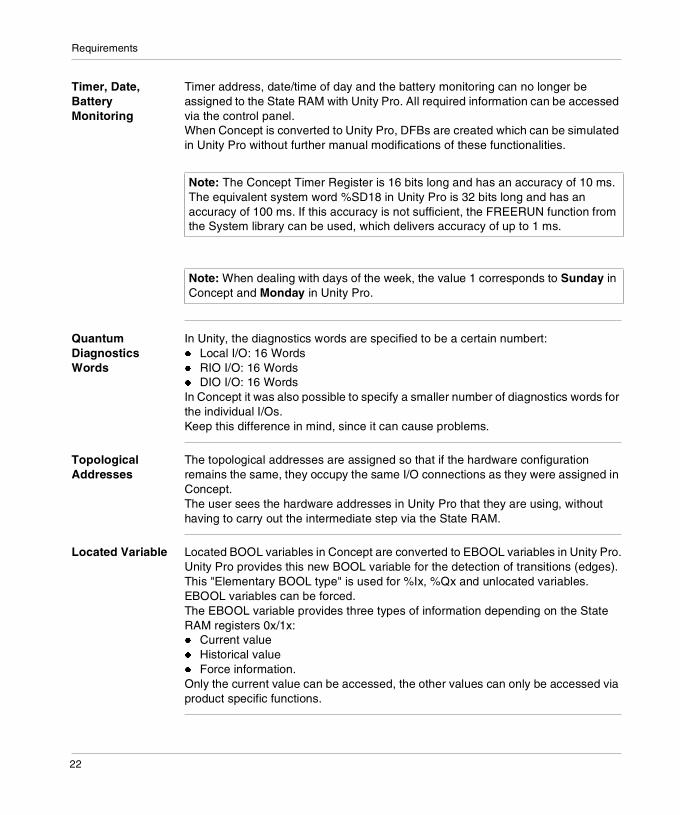
Timer, Date, Battery Monitoring
Timer address, date/time of day and the battery monitoring can no longer be assigned to the State RAM with Unity Pro. All required information can be accessed via the control panel.When Concept is converted to Unity Pro, DFBs are created which can be simulated in Unity Pro without further manual modifications of these functionalities.
Quantum Diagnostics Words
In Unity, the diagnostics words are specified to be a certain numbert:� Local I/O: 16 Words� RIO I/O: 16 Words� DIO I/O: 16 WordsIn Concept it was also possible to specify a smaller number of diagnostics words for the individual I/Os.Keep this difference in mind, since it can cause problems.
Topological Addresses
The topological addresses are assigned so that if the hardware configuration remains the same, they occupy the same I/O connections as they were assigned in Concept.The user sees the hardware addresses in Unity Pro that they are using, without having to carry out the intermediate step via the State RAM.
Located Variable Located BOOL variables in Concept are converted to EBOOL variables in Unity Pro.Unity Pro provides this new BOOL variable for the detection of transitions (edges). This "Elementary BOOL type" is used for %Ix, %Qx and unlocated variables.EBOOL variables can be forced.The EBOOL variable provides three types of information depending on the State RAM registers 0x/1x:� Current value� Historical value� Force information.Only the current value can be accessed, the other values can only be accessed via product specific functions.
Note: The Concept Timer Register is 16 bits long and has an accuracy of 10 ms. The equivalent system word %SD18 in Unity Pro is 32 bits long and has an accuracy of 100 ms. If this accuracy is not sufficient, the FREERUN function from the System library can be used, which delivers accuracy of up to 1 ms.
Note: When dealing with days of the week, the value 1 corresponds to Sunday in Concept and Monday in Unity Pro.
22

Requirements
Longer cycle time via EBOOL
In Unity, as opposed to Concept, the edges and force information is updated from EBOOL variables during program runtime.For this reason on the Quantum CPU 434, CPU 534 and CPU 311 platforms, the assignment of EBOOL variables is only half as fast as the assignment of BOOL variables.
Constants Constants in Concept are converted to write-protected variables in Unity Pro.Unity Pro does not provide constants. Comparable functionality is achieved using write-protected variables.
0x Register In Concept, the 0x registers are not buffered. They are reset to zero with every warm restart.In Unity Pro, the 0x registers are buffered ("RETENTIVE", "VAR_RETAIN"), i.e. Conform to IEC.Do not use the possibility to set the 0x register to zero on every warm restart if you use a project in Concept that you want to convert to Unity Pro.
Note: If you need variables in the signal memory, use BOOL variables and assign them to the memory area %MW (e.g. BoolVar : BOOL AT %MW10). Otherwise use unlocated BOOL variables.
Note: If you require non-buffered behavior, define the warm restart event with the SYSSTATE function block and explicitly copy the value 0 (zero) to the 0x register.
23
Requirements
Quantum Remote I/O Control
In Concept, only LL984 sections can be assigned I/O stations (Drops). This is not possible in Concept projects with IEC conforming sections (FBD, LD, SFC, IL, ST).Unity Pro offers this option, in which a logic is recreated in accordance with LL984. This logic must be entered manually, however.Example of a section processing order in Unity Pro:
Section n-2Section n-1RIO call (u,v,w)Section nSection n+1RIO call (u+1,w,x)Section n+2RIO call (u+2,x,y)
RIO (x,y,z) is the explicit I/O call here:� Write the outputs to the I/O station x.� Wait at the inputs of the I/O station y.� Prepare the inputs of the I/O station z.
Setting Variables Cyclically
Unlocated variables cannot be set cyclically in Unity Pro. (It is possible in Concept).If you need to set variables cyclically in your project, you should use located variables.0x/1x registers (EBOOL) can be forced.3x/4x registers can be set cyclically (only numerical values).
Note: Take these new settings into consideration when structuring your project.
24

Requirements
EFBs
General The following options are available for converting Concept EFBs to Unity Pro:� The EFBs are also supported in Unity Pro; They are mapped on a one to one
basis.� The EFBs are no longer supported by Unity Pro.
Instead of EFBs appropriate DFBs are placed in the application. The functionality remains unaffected by this.
� The EFBs are no longer supported by Unity Pro. Instead of EFBs, DFBs with no programmatic content are placed in the application. These DFBs contain all the Concept parameters. An error message is displayed that says that the programmatic content for these DFBs must still be created.
DIAGNO library When converting Concept to Unity Pro for all DIAGNO blocks the station parameter is omitted.The following EFBs from the DIAGNO library in Concept are converted to empty DFB’s in Unity Pro. � ACT_DIA� XACT_DIA� ERR2HMI� ERRMSG
When creating programs in Unity Pro instead of the ACT_DIA and XACT_DIA EFBs use the XACT EFB.For all DIAGNO blocks which can be extended in Concept (D_PRE, D_GRP ...), the extensible inputs (IN1 ... INx) are gathered together in oneinput. This is implemented using a nested logic AND link. In the FBD language the AND block is positioned at the same location as the DIAGNO block by the converter. This overlap must be resolved manually by the user.
SYSTEM library The SKP_RST_SCT_FALSE and LOOPBACK EFBs cannot be used in Unity Pro.
FUZZY library The FUZZY library is no longer supported by Unity Pro.
Note: These DFBs, created in Unity Pro have all the Concept parameters but no programmatic content. An error message is displayed that says that the programmatic content for these DFBs must still be created.
25
Requirements
HANDTABL library
The HANDTABL library is no longer supported by Unity Pro.
EXPERTS library The following Concept EFBs are converted to DFBs in Unity Pro: � ERT_TIME� SIMTSX22� EFBs from the EX family� EFBs from the MVB family� EFBs from the ULEX family
The data structures DPM_TIME and ERT_10_TTAG from the time stamp module 140 ERT 854 10 have been changed. The MS element was broken up into MS_LSB and MS_MSB. For more information about this, see State RAM assignment using derived data types, p. 20.Outputs which describe data structures must be assigned event variables using the (=>) assignment operator within the parameter brackets in the ST and IL languages. This happens automatically during conversion (from Unity 2.0 onwards). The functionality remains the same but the section of the program looks a little different.
Converted EFBs During conversion, Unity Pro standardizes the EFB offer by grouping redundant EFBs. The respective EFBs are automatically converted and the project adjusted accordingly.
Renamed EFBs The following diagnostics EFBs are renamed when converting Concept to Unity Pro:
The Quantum configuration EFB for the Backplane Expander 140 XBE 100 00 is renamed when converting Concept to Unity Pro:
Note: These DFBs created in Unity Pro have all the Concept parameters but no programmatic content. An error message is displayed that says that the programmatic content for these DFBs must still be created.
Concept Unity Pro
XACT D_ACT
XREA_DIA D_REA
XLOCK D_LOCK
XGRP_DIA D_GRP
XDYN_DIA D_DYN
XPRE_DIA D_PRE
Concept Unity Pro
XBP XBE
26

Requirements
Programming Language SFC
General For some programming languages there are restrictions to observe when converting a project from Concept to Unity Pro.
Parallel/Alternative Sequence
A parallel branch may not be directly followed by an alternative branch.This type of sequence is not permitted according to IEC 1131.Unity Pro does not support this type of sequence, although it is possible in Concept.The converter transfers this type of project to Unity Pro, but manual modifications are subsequently required.This problem can be solved by inserting an dummy step between the branches.
S_5_12
a
S_5_10 S_5_11
S_5_13
b
S_5_16
g
S_5_14
c
S_5_15
d
e f
S_5_12
a
S_5_10 S_5_11
S_5_13
b
S_5_14
c
S_5_15
d
e f
27

Requirements
Programming Language LD
General For some programming languages there are restrictions to observe when converting a project from Concept to Unity Pro.
Converting the graph
When converting a Concept project to Unity Pro, the ladder diagram LD graph is also converted, which can lead to a restructuring of the graph.Concept Application Converter (Unity Pro 2.0.2) was modified. For behaviour changes please refer to FAQs.
Programming Language ST/IL
General For some programming languages there are restrictions to observe when converting a project from Concept to Unity Pro.
Generic EFBs Only call generic EFBs instances once.Using Concept 2.2, assign the outputs directly after the EFB call of a variable.
Syntax with Concept 2.5
Only use the new syntax for Concept 2.5 (from Unity V2.0 onwards it is automatically converted).Syntax with Concept 2.5:
GenEFB(in1:=x1, in2:=x2, out1=>x3, out2=>X4;
in1, in2, out1 and out2 are type ANY.
28

Requirements
Generic EFBs in Concept
List of generic EFBs in Concept:� COMM library
� XXMIT� CONT_CTL library
� DEADTIME� EXTENDED library
� HYST� INDLIM� LIMD� SAH
� LIB984 library� FIFO� LIFO� R2T� SRCH� T2T� GET_3X� GET_4X� PUT_4X
Declaring EFBs The declaration of EFBs in Unity Pro is found in the variables editor and no longer in the ST/IL sections as with Concept.EFBs declared this way are no longer limited to only one section.
Programming Language LL984
General For some programming languages there are restrictions to observe when converting a project from Concept to Unity Pro.
LL984 is no longer supported by Unity Pro
Unity Pro only supports IEC conforming programming. The programming languages LL984 and LL984 specific configurations are not supported by Unity Pro.Concept sections, created using the LL984 programming language, are converted to the LD programming language in Unity Soft (from Unity Pro V2.0 onwards).See also Restrictions for old LL984 Configurations, p. 15.
29

Requirements
Programming Language FBD
General For some programming languages there are restrictions to observe when converting a project from Concept to Unity Pro.
Macros When converting a Concept project to Unity Pro, sections created using macros are also converted.These sections can also be manually copied and modified.
30

3
Language differencesIntroduction
Overview This chapter contains information about language differences.
What's in this Chapter?
This chapter contains the following topics:
Topic Page
Functions Not Present in Unity 32
EFB replaced by function 32
INOUT parameters 33
Parameter type changed 33
ANY_ARRAY_WORD parameters 34
Unique Naming required 35
Incomplete LD Generation 35
LD Execution Order Changed 36
Constants 40
Indices in ST 40
Calculate with TIME and REAL 40
WORD Assignments to BOOL Arrays 40
Topological Address Overlapping 41
Structure Alignment Changed 41
Undefined Output on Disabled EFs 42
SFC Section Retains its State When Performing an Online Modification 43
Weekday Numbering 44
System Timer 44
Initial Values 45
Macros 46
31

Language differences
Functions Not Present in Unity
DFB wrapper Functions from Concept that are not present in Unity get a DFB wrapper if they are called in ST sections (e.g., WORD_AS_UDINT). For example:WAUD(* UDINT *) := WORD_AS_UDINT (LOW := WAUL, (* WORD *) HIGH := WAUH(* WORD *));. . . looks like this after conversion:WAUD(* UDINT *) := FBI_ST1_75_33 (LOW := WAUL, (* WORD *)HIGH := WAUH(* WORD *));
Manual correction
FBI_ST1_75_33 is the instance name of the provided DFB wrapper. However, the call is still invalid for the analyzer because the converter cannot yet do multi-object syntax corrections in ST. (Will be present in V2.0).You must correct this manually to:FBI_ST1_75_33 (LOW := WAUL, (* WORD *) HIGH := WAUH(* WORD *), OUT => WAUD);
EFB replaced by function
Error message Some standard Concept EFBs are implemented in Unity as functions.If the converted application contains (in an ST or IL section) a call to such an EFB, an error will be generated while analyzing the project.The following figure is a sample explanation of the SET_BIT function block:
Manual correction
The SET_BIT function officially replaces SET_BITX, which is not implemented in UNITY. SET_BIT now is a function, and therefore the instance has been eliminated and the function name itself has been inserted instead. However, an additional manual correction of the call is required. The converter does not do multi-object syntax corrections in ST or IL (will be present in V2.0). Since this is a function call, the result must appear on the left side of a function assignment:res1 := SET_BIT(IN := true, NO := 4);
32

Language differences
INOUT parameters
Manual Correction
INOUT parameter syntax in ST (and IL) must be corrected manually. Examples are shown:Ascii_FIFO_OUT (Pile := AscFifo_Mess); .....
AscFifo_Out := Ascii_FIFO_OUT.DataOut;. . . is manually corrected to:Ascii_FIFO_OUT (Pile := AscFifo_Mess, DataOut => AscFifo_Out);
Output Parameters
INOUT parameters in ST sections that were output parameters in Concept (e.g., DataOut of FIFO) must be moved manually in ST and IL to the parameters inside parentheses associated with the call.If INOUT parameters that were outputs only in Concept are connected only to a link at the output side, they must get a manually declared variable at the input side as well. The link must be deleted if it is not connected to another IN/OUT variable. Targets of the deleted link must be assigned to the manually declared variable.This is done automatically in V2.0.
Change of Variable Type
The converter changes the type of direct variables at INOUT parameters of communication blocks to ARRAY[0..0] OF WORD. This must be corrected manually to correspond to the size of the array.
Parameter type changed
Change The parameter type has been changed from type WORD to an array of located words.
Explanation Unity Comm EFBs no longer accept a single WORD address for the communication field because more than one WORD is written. So the converter introduces an artificial array (shown in the conversion report) that can be reached from the project tree through the appropriate hyperlink:"For var WORD1 type ARRAY[0..0] OF WORD generated"The array has a single word size because the converter can not determine its size. The user, therefore, needs to manually configure the correct array size.
33
Language differences
ANY_ARRAY_WORD parameters
Error Message For EF/EFB pins that have the type WORD in Concept and have been changed to ANY_ARRAY_WORD in Unity, "Cannot import variables" will be the reported type. Such pins usually have a single register address as a formal parameter in Concept, but it is actually used to point to an array of words for which the size has not been explicitly declared.
Change of Parameter Type
In Unity, an array of words has to be declared for this purpose. This is why the converter changes the type to ARRAY[0..0] OF WORD.However, the converter cannot determine the required size because a size declaration is absent in the Concept application. Therefore, the converter defines one data element, [0..0], as a replacement for the original variable.It is up to the user to replace this default range of one element with the number of elements required by the application.
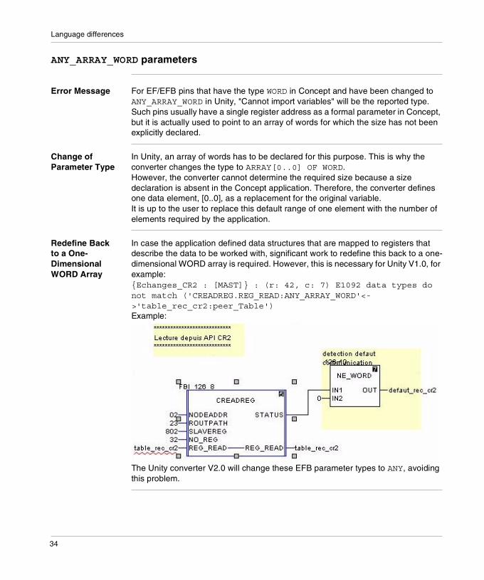
Redefine Back to a One-Dimensional WORD Array
In case the application defined data structures that are mapped to registers that describe the data to be worked with, significant work to redefine this back to a one-dimensional WORD array is required. However, this is necessary for Unity V1.0, for example: {Echanges_CR2 : [MAST]} : (r: 42, c: 7) E1092 data types do not match ('CREADREG.REG_READ:ANY_ARRAY_WORD'<->'table_rec_cr2:peer_Table')Example:
The Unity converter V2.0 will change these EFB parameter types to ANY, avoiding this problem.
34

Language differences
Unique Naming required
Unique name In Concept applications, section names can have the same name as a DDT. That is not the case in Unity. The converter checks section names to see if they are redundant of DDT names. If so, the converter appends "_Sect" to the section name.
Incomplete LD Generation
LD Generation Not Done Completely
In some cases, LD generation cannot be completed. This can happen when the algorithm allows an object that requires the same position as an existing object. In these cases, the pre-existing object is overwritten.Messages are issued to make you aware of this:{SAFETY_INTERLOCKS_PLC3 : [MAST]} :(r: 8, c: 3) E1189 converter error: 'Overwrite happened when generating LD network - see report'
{SAFETY_INTERLOCKS_PLC3 : [MAST]} : (r: 8, c: 3) E1002 syntax error
Details in Conversion Report
In the conversion report, which may be opened after being imported through the hyperlink in the project tree, some additional detail about the message is given:09:29:05.953 > Error: LD Object PTFDTP1_ENABLED with type coil overwrittenThe user should compare the conversion result to a printout of the original section and correct the converted section accordingly.
35

Language differences
LD Execution Order Changed
Different Execution Orders
The converter follows the Concept execution order in graphical positioning, making the original order visible to the user. However, since Unity calculates the order anew (without the possibility of forcing it from the converter), there can be execution order discrepancies.
Note: Unity’s LD execution order can differ from Concept’s. In Unity, one LD network can be completed before the next is started.
36

Language differences
Concept When analyzing in Concept, the execution order is calculated. The result is shown in parentheses after the instance names in this image.The selected block is executed in the middle of the other network, even though it has no direct connection to it. Concept calculates the execution order from the block position.This is the original section as it appears in Concept:
The used variables are initialized in a way that the result of the comparator EQ_INT becomes "true" after execution of the first cycle in Concept:
37
Language differences
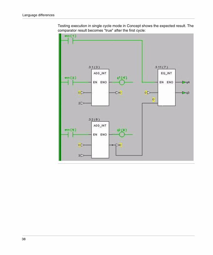
Testing execution in single cycle mode in Concept shows the expected result. The comparator result becomes "true" after the first cycle:
38

Language differences
Unity The converted network reflects the Concept execution order in the graphical position of the blocks:
The image also shows the execution status stopped at a breakpoint in the first cycle. The comparator EQ_INT is already executed and will not deliver a "true" result because the first ADD_INT integrator block is executed after it.
Solution Replace the connection via a variable by a link to achieve the same result as in Concept.
39

Language differences
Constants
Losing the Read-Only Behavior
Constants are not accepted as private DFB variables. Therefore, they are converted to initialized variables in DFBs, in this way losing the read-only behavior.
Indices in ST
ResolutionConcept Application Converter (Unity Pro 2.0.2) was modified. For behaviour changes please refer to FAQs.
Calculate with TIME and REAL
Manual Correction
When TIME and REAL variables are multiplied in ST, REAL_TO_DINT must be inserted into the REAL variable manually.
WORD Assignments to BOOL Arrays
Manual Correction
Assignments of HEX WORDS to complete Bool arrays sent to Word registers are possible in Concept, but not in Unity. A manual correction must be done, for example:('AR2_BOOL[0]:BOOL'<->'16#0100:DINT')
('AR2_BYTE[0]:BYTE'<->'16#55AA:DINT')
('AR2_BYTE[0]:BYTE'<->'16#AA55:DINT')
Solution The ST code must be changed to single-component assignments. The hex word must be split into single bits: AR2_BOOL[17] := true;
40

Language differences
Topological Address Overlapping
Same Topological Address
In Unity, you are warned (during application analysis) if the same topological address is assigned to multiple variables.
Structure Alignment Changed
DPM_Time Structure
Unity uses a 2-byte alignment for structures in contrast to Concept (1-Byte) to speed up the access to structure components. This affects system structures mapped to StateRam, because the same structures in Unity can be bigger including some byte gaps.The concerned structure is DPM_Time, which has been redefined for Unity to re-map to the correct hardware addresses.Concept’s DPM_Time definition:sync: BOOLms: WORD...Unity’s DPM_Time definition:sync: BOOLms_lsb: BYTEms_msb: BYTE...
Manual Correction
If an application that includes the DPM_time structure is converted, the analyze/build process will fail for the redefined structure components (in the above example, ms_lsb, ms_msb). The user has to manually change the usage of these structure components in the application accordingly.
41

Language differences
Undefined Output on Disabled EFs
Outputs of EFs Not Kept
In case the EN switches from TRUE to FALSE, the outputs of EFs from the previous cycle are not kept in Unity. This reduces the memory consumption in the PLC. This is different from EFBs, which keep their value from the previous cycle. Concept uses static links to latch the value from the previous cycle.
Execution Behavior Differs Significantly
If a Concept application relies on the outputs of EFs to keep their old values, the execution behavior in UNITY will differ significantly.
Manual Correction
The application has to be changed manually. Links from outputs, which are assumed to keep their value, need to be replaced by variables. If the EN of an EF is set to false, the EF is not executed and a connected variable is not touched.
Concept The output of the disabled SEL EF is kept and used as input for the EQ_INT function block:
42

Language differences
Unity The output of the disabled SEL EF gets an undefined value, in this case 0. Therefore the output of EQ_INT function block has become true:
Solution If the EN of the SEL is set to false, the ENO of the EQ_INT is also set to false, but the connected output variable keeps its value from the previous cycle:
SFC Section Retains its State When Performing an Online Modification
Online Modifications Without Resetting
In Unity it is possible to do online modifications of an SFC chart without resetting it. The SFC chart retains its state and will continue the execution.
Note: The use of a variable is mandatory to retain network results in case an EF becomes disabled.
Note: In Concept, the online modification of an SFC chart usually results in the resetting of the chart.
43

Language differences
Weekday Numbering
Different Numbering
In Unity the numbering of weekdays is different than Concept:
SET_TOD / GET_TOD
Function blocks: SET_TOD and GET_TOD will be converted to Unity as DFBs, which work in both directions. Because SET_TOD expects a "Concept" numbered weekday and translates it as a Unity coded value. Also the GET_TOD reads Unity value and returns to User the Concept value.
System Word %SW49
System Timer
Concept Concept’s system timer was located on a user-defined register word (16-bit) and incremented at 10 ms.
Unity Unity provides an incremental timer with 100 ms updating (%SD18). A 10 ms timer can be logically created using the FREERUN function (sec timer).
Number Unity Concept
1 Monday Sunday
7 Sunday Saturday
Note: We do not recommend that you mix GET_TOD and SET_TOD programming with the use of system words (e.g. %SW49) in the same application.
44
Language differences
Initial Values
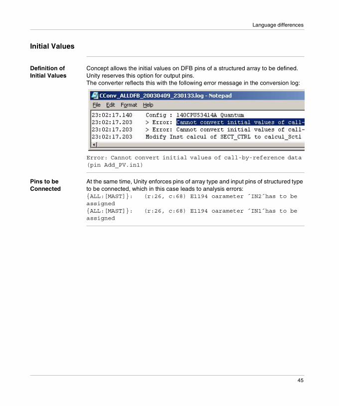
Definition of Initial Values
Concept allows the initial values on DFB pins of a structured array to be defined. Unity reserves this option for output pins.The converter reflects this with the following error message in the conversion log:
Error: Cannot convert initial values of call-by-reference data (pin Add_PV.in1)
Pins to be Connected
At the same time, Unity enforces pins of array type and input pins of structured type to be connected, which in this case leads to analysis errors: {ALL:[MAST]}: (r:26, c:68) E1194 oarameter ´IN2´has to be assigned{ALL:[MAST]}: (r:26, c:68) E1194 oarameter ´IN1´has to be assigned
45

Language differences
Solution To solve this problem, create a variable of the pin’s type and initialize it with the original values.Connect this constant to the appropriate pin of each DFB instance.Example
Solution: Add initialized variable.
Macros
Macros Replaced by Dummy DFBs
Macros (name starting with @) are refused by the converter because Unity does not implement macros. However, if you try to import an application containing macros, they will be replaced by dummy DFBs (as indicated by the '~' character in the application name).While analyzing the project, you will get error messages regarding these dummy DFBs. To correct these errors, simply remove all of the DFBs that were created as a replacements for macros.
AXx, EPARx Parameters
AXx and EPARx parameters in Concept’s extensible motion blocks are automatically invoked with the newly required array instead of with Unity’s formerly present extensible pins. Constants present at the Concept pins are also placed as initialization values to such arrays. However, variables and links must be attached manually with move blocks to these arrays.
46

4
Possible application behavior changeIntroduction
Overview This chapter contains information about possible application behavior change, when migrating from Concept to Unity Pro.
What's in this Chapter?
This chapter contains the following topics:
Topic Page
General 48
Concept behavior 49
IEC demands 50
Unity behavior 52
Consequences 54
47

Possible application behavior change
General
Concept In Concept all parameters of EFBs (Elementary Function Blocks) were generally handled by reference. Because of this it was possible without any problem to modify a variable connected to an output of a function block from another location inside the application or by an HMI tool, when the function block was NOT writing the output. This behavior was used to realize for example the manual mode of closed-loop-control function blocks.
Changes in Unity Because of IEC compliance the parameter handling was changed from Concept to Unity and the way of multi-assignment described above doesn't work any longer.
Behavior may change
If an application is converted from Concept to Unity and uses this way of multi-assignment, the behavior may change in some use cases in a way that the output connected variable is no longer modifiable from another location.
Note: If the application uses multi-assignment on EFB outputs, you should carefully read the following chapter to verify that the converted application works in the intended way.
48

Possible application behavior change
Concept behavior
Parameters are handled by reference
In Concept all function block parameters are handled by reference, means the blocks receives a pointer to the data of every function block pin and works directly on the connected variable.Connected variables:
Function block code
Therefore in Concept it is up to the function block code to decide whether:� to behave IEC compliant or� to write input data or� to read output data or � not to write output data.
Instance data
EFB Code
Connected output variableConnected input variable
49

Possible application behavior change
IEC demands
Function block For the purposes of programmable controller programming languages, a function block is a program organization unit which, when executed, yields one or more values. Multiple, named instances (copies) of a function block can be created. Each instance shall have an associated identifier (the instance name), and a data structure containing its output and internal variables, and, depending on the implementation, values of or references to its input variables. All the values of the output variables and the necessary internal variables of this data structure shall persist from one execution of the function block to the next.Therefore, invocation of a function block with the same arguments (input variables) need not always yield the same output values.
Assignment of a value
Assignment of a value to an output variable of a function block is not allowed except from within the function block.The assignment of a value to the input of a function block is permitted only as part of the invocation of the function block.Unassigned or unconnected inputs of a function block shall keep their initialized values or the values from the latest previous invocation, if any.Allowable usage of function block inputs and outputs are summarized in table below, using the function block FF75 of type SR.The examples are shown in the ST language.
Usage Inside function block Outside function block
Input read IF IN1 THEN ... Not allowed 1, 2
Input assignment
Not allowed 1 FB_INST(IN1:=A,IN2:=B);
Output read OUT := OUT AND NOT IN2; C := FB_INST.OUT;
Output assignment
OUT := 1; Not allowed 1
In-out read IF INOUT THEN ... IF FB1.INOUT THEN...
In-out assignment
INOUT := OUT OR IN1; 3 FB_INST(INOUT:=D);
1 Those usages listed as "not allowed" in this table could lead to implementation-dependent, unpredictable side effects.
2 Reading and writing of input, output and internal variables of a function block may be performed by the "communication function", "operator interface function", or the "programming, testing, and monitoring functions" defined in IEC 61131-1.
3 Modification within the function block of a variable declared in a VAR_IN_OUT block is permitted.
50

Possible application behavior change
EN and ENO in function blocks
For function blocks also an additional Boolean EN (Enable) input or ENO (Enable Out) output, or both, can be provided by the manufacturer or user according to the declarations.When these variables are used, the execution of the operations defined by the function block shall be controlled according to the following rules:1. If the value of EN is FALSE (0) when the function block instance is invoked, the
assignments of actual values to the function block inputs may or may not be made in an implementation-dependent fashion, the operations defined by the function block body shall not be executed and the value of ENO shall be reset to FALSE (0) by the programmable controller system.
2. Otherwise, the value of ENO shall be set to TRUE (1) by the programmable controller system, the assignments of actual values to the function block inputs shall be made and the operations defined by the function block body shall be executed. These operations can include the assignment of a Boolean value to ENO.
3. If the ENO output is evaluated to FALSE (0), the values of the function block outputs (VAR_OUTPUT) keep their states from the previous invocation.
In-out variables In-out variables are a special kind of variable used with program organization units (POUs), i.e., functions, function blocks and programs. They do not represent any data directly but reference other data of the appropriate type. They are declared by use of the VAR_IN_OUT keyword. In-out variables may be read or written to.Inside a POU, in-out variables allow access to the original instance of a variable instead of a local copy of the value contained in the variable.
Function block invocation
A function block invocation establishes values for the function block's input variables and causes execution of the program code corresponding to the function block body.These values may be established graphically by connecting variables or the outputs of other functions or function blocks to the corresponding inputs, or textually by listing the value assignments to input variables. If no value is established for a variable in the function block invocation, a default value is used. Depending on the implementation, input variables may consist of the actual variable values, addresses at which to locate the actual variable values, or a combination of the two. These values are always passed to the executing code in the data structure associated with the function block instance. The results of function block execution are also returned in this data structure. Hence, if the function block invocation is implemented as a procedure call, only a single argument - the address of the instance data structure - need be passed to the procedure for execution.
51

Possible application behavior change
Unity behavior
Changed parameter handling
To fulfill the IEC demands the normal EDT (Elementary Data Types) parameter handling was changed from Concept to Unity.The following figure describes the actual implementation in Unity.
The EFBs no longer get pointers to their connected pin variables. They always get the data by value. In every scan the application code updates the copy of the input data in the instance data, before the function block is called (1). The copy of the pin data is located in the instance data of the block and the function block code always works on the instance data (2). After the function block code execution the application code copies the updated function block output data from the instance data to the connected output variables (3).This is valid for all EDTs. Derived data types and more complex data types are treated still by reference in some cases.
Copy of inputs
Connected output variableConnected input variable
Instance data
EFB Code
Copy of outputs
1
2
3
52

Possible application behavior change
Addressing modes
The addressing mode of a Function Block element is directly linked to the type of the element.The currents known addressing modes are:� by value (VAL)� by address (L-ADR)� by address + Number of elements (L-ADR-LG)Table with four columns and legend
Function Block invocation
The following rules must be taken into account while invoking a Function Block instance:� All input_output parameters have to be filled� All input parameters using the L-ADR or L-ADR-LG addressing modes have to
filled� All output parameters using the L-ADR or L-ADR-LG addressing modes have to
filledAll other kind of parameters could be omitted while Function Block Instance invocation. For input parameters, the following rules are applied (in the given order):� The values of the previous invocation are used.� If no previous invocation, the initial values are used.
- EDT (Except STRING)
STRING DDT Array DDT Struct
ANY_ ARRAY
ANY...
Input parameter
VAL L-ADR-LG L-ADR-LG L-ADR L-ADR-LG L-ADR-LG
Input_Output parameter
L-ADR 1 L-ADR-LG L-ADR-LG L-ADR L-ADR-LG L-ADR-LG
Output parameter
VAL VAL L-ADR-LG VAL L-ADR-LG L-ADR-LG
Public Variable
VAL VAL - VAL - -
Private Variable
VAL VAL - VAL - -
1 Except for BOOL type, the addressing mode is VAL.
53

Possible application behavior change
Consequences
Potential problems
Because of this architectural change there might be trouble, when an application is migrated from Concept to Unity in the following cases: � Multi assignment of connected output variables:
In Concept there are function blocks, mainly in the closed-loop-control area, which do not write their output values to the connected variables in special operating modes (manual mode). In these special modes it was possible to write the variables from other locations inside the application. This will work in Unity only, if the variables are written after the function block call.If they are written before the function block call, the copy process from the instance data to the connected variables will overwrite this value with the old value from the instance data.
� Controlling output variables by animation table or HMI:If a block doesn't write his outputs in special operating modes (like manual mode, see above), it was possible to modify the connected output variables by animation tables or HMI.This will no longer work in Unity, since the copy process from the instance data to the connected variables of the function block will overwrite the modified value with the old value from the instance data.
54

Possible application behavior change
Changed EFB layout
To avoid major problems, a lot of function blocks (mainly in the Motion and CLC area) were changed in their layout from Concept to Unity to ensure a correct mode of operation in the intended way for the function blocks.The concerned pins were changed from type OUT to IN/OUT. In nearly all cases the modification meets better the reality, since it is read from the concerned output pins and so they are in fact IN/OUTs.The following tables summarize the EFBs, where at least one pin was changed from OUT to IN/OUT during migration from Concept to Unity.Library CONT_CTL:
Library Motion:
Family Function Block Concerned Pin
Controller PI_B OUT
PIDFF OUT
Output Processing MS OUT
Setpoint Management SP_SEL SP
Family Function Block Concerned Pin
MMF Start CFG_CP_F MFB, CFG_BLK
CFG_CP_V MFB, CFG_BLK
CFG_CS MFB, CFG_BLK
CFG_FS MFB, CFG_BLK
CFG_IA MFB, CFG_BLK
CFG_RA MFB, CFG_BLK
CFG_SA MFB, CFG_BLK
DRV_DNLD MFB
DRV_UPLD MFB
IDN_CHK MFB
IDN_XFER MFB
MMF_BITS MFB
MMF_ESUB MFB
MMF_INDX MFB
MMF_JOG MFB
MMF_MOVE MFB
MMF_RST MFB
MMF_SUB MFB
MMF_USUB MFB
55

Possible application behavior change
Library Obsolete Lib:
Concept Converter behavior
The Concept Converter normally handles the layout change in the following way, when a Concept application is imported into Unity:� Case 1: A variable is connected to the output pin in Concept:
The Concept Converter keeps the variable at the output side of the IN/OUT pin and adds the variable additionally at the input side of the pin.
� Case 2: A link is connected to the output pin in Concept:The Concept Converter removes the link, creates a new variable of the needed type and writes this new variable to the start and end position of the removed link. Additionally the variable is added to the input side of the pin.
Family Function Block Concerned Pin
CLC_PRO ALIM Y
COMP_PID Y, YMAN_N, OFF_N, SP_CAS_N
DERIV Y
INTEG Y
LAG Y
LAG2 Y
LEAD_LAG Y
PD_OR_PI Y
PI Y
PID Y
PID_P Y
PIP Y
PPI Y
VLIM Y
Extensions/Compatibility
R2T OFF
SRCH INDEX
T2T OFF
56

Possible application behavior change
Further potential problems
The following tables contain blocks, where also trouble may arise in case of multi-assignment, because in Concept:� The blocks do not write their listed output pin in case of errors inside the block.� The blocks do not write their listed output pin in COLD or WARM INIT scan.� The blocks write their listed output pin conditionally depending from internal mode
of operation.Library CONT_CTL:
Library I/O Management:
Family Function Block Concerned Pin
Conditioning DTIME OUT
SCALING OUT
TOTALIZER OUT, INFO
Controller AUTOTUNE TRI, INFO
PI_B OUT_D, DEV
PIDFF OUT_D, INFO
STEP2 DEV
STEP3 DEV
Output Processing MS OUTD, STATUS
MS_DB OUTD, STATUS
SPLRG OUT1, OUT2
Setpoint Management RAMP SP
RATIO KACT, SP
SP_SEL LSP_MEM
Family Function Block Concerned Pin
Analog I/O Configurationj
I_SET CHANNEL
O_SET CHANNEL
Analog I/O Scaling I_NORM_WARN WARN
I_PHYS_WARN WARN
I_SCALE_WARN WARN
Quantum I/O Configurationj
ACI040 CHANNL1..16
ACO130 CHANNEL1..8
AII330 CHANNEL1..8, INTERNAL
AII33010 CHANNEL1..8
AIO330 CHANNEL1..8
ARI030 CHANNEL1..8
57

Possible application behavior change
Library Motion:
Family Function Block Concerned Pin
MMF Start CFG_CP_F Q, ERROR
CFG_CP_V Q, ERROR
CFG_CS Q, ERROR
CFG_FS Q, ERROR
CFG_IA Q, ERROR
CFG_RA Q, ERROR
CFG_SA Q, ERROR
DRV_DNLD Q, ERROR, IDN_CNT
DRV_UPLD Q, ERROR, REG_CNT, DATA_B, LK
IDN_CHK Q, ERROR, NOT_EQ
IDN_XFER Q, ERROR, OUT_RAW, OUTCONV
MMF_ESUB Q, ERROR, RET1, RET2, RET§
MMF_INDX Q, ERROR
MMF_JOG Q, ERROR
MMF_MOVE Q, ERROR
MMF_RST Q
MMF_SUB Q, ERROR, RET1, RET2, RET§
MMF_USUB Q, ERROR, RET1, RET2, RET§
58

Possible application behavior change
Library Obsolete Lib:
Family Function Block Concerned Pin
CLC DELAY Y
PI1 ERR
PID1 ERR
PIDP1 ERR
THREE_STEP_CON1 ERR_EFF
THREEPOINT_CON1 ERR_EFF
TWOPOINT_CON1 ERR_EFF
CLC_PRO COMP_PID STATUS, ERR
DEADTIME Y
FGEN Y, N
INTEG STATUS
PCON2 ERR_EFF
PCON3 ERR_EFF
PD_OR_PI ERR, STATUS
PDM Y_POS, Y_NEG
PI ERR, STATUS
PID ERR, STATUS
PID_P ERR, STATUS
PIP ERR, SP2, STATUS
PPI ERR, SP2, STATUS
PWM Y_POS, Y_NEG
QPWM Y_POS, Y_NEG
SCON3 ERR_FF
VLIM STATUS
Extensions/Compatibility
FIFO EMPTY, FULL
LIFO EMPTY, FULL
Note: The pins were not changed, because in normal operation mode of the blocks this has no influence.
59

Possible application behavior change
60

5
The Conversion ProcessConversion Process
General A Concept project is exported from Concept and then converted automatically into a Unity Pro project using the Unity Pro Concept Converter.
61
The Conversion Process
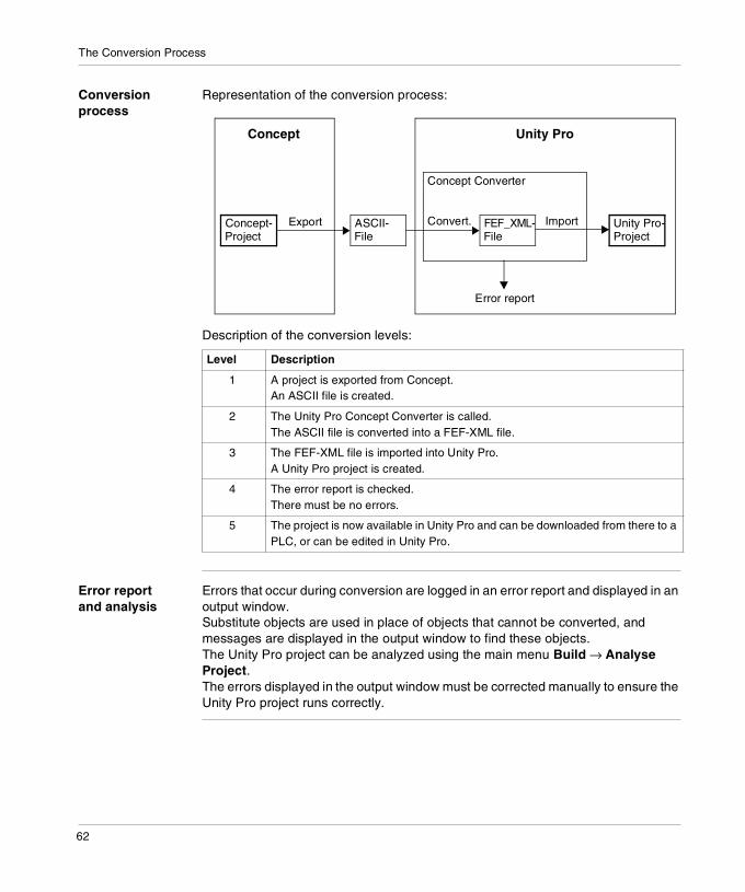
Conversion process
Representation of the conversion process:
Description of the conversion levels:
Error report and analysis
Errors that occur during conversion are logged in an error report and displayed in an output window.Substitute objects are used in place of objects that cannot be converted, and messages are displayed in the output window to find these objects.The Unity Pro project can be analyzed using the main menu Build → Analyse Project.The errors displayed in the output window must be corrected manually to ensure the Unity Pro project runs correctly.
Level Description
1 A project is exported from Concept.An ASCII file is created.
2 The Unity Pro Concept Converter is called.The ASCII file is converted into a FEF-XML file.
3 The FEF-XML file is imported into Unity Pro.A Unity Pro project is created.
4 The error report is checked.There must be no errors.
5 The project is now available in Unity Pro and can be downloaded from there to a PLC, or can be edited in Unity Pro.
Concept-Project
Unity Pro-Project
FEF_XML-File
ASCII-File
Export Convert. Import
Concept Converter
Concept Unity Pro
Error report
62

6
Conversion ProcedureIntroduction
Overview This chapter contains the procedures required to convert a Concept project into a Unity Pro project.
What's in this Chapter?
This chapter contains the following topics:
Topic Page
Exporting a Project from Concept 64
Importing a Project into Unity Pro 65
63

Conversion Procedure
Exporting a Project from Concept
General A Concept project that should be used in Unity Pro must first be exported from Concept. It is then possible to use the Unity Concept Converter to make the conversion to a Unity Pro project.
Export project Perform the following steps to export a project:
Step Procedure
1 Start the Concept Converter program from the Concept program group.
2 Select File → Export..., to open the menu for selecting the export range.
3 Select the export range:� Project with DFBs: All project information including the DFBs and data
structures (derived data types) used in the project are exported.� Project without DFBs: All project information including all data structures
(derived data types), but not DFBs and macros, is exported.Result: The dialog box for selecting the files to be exported is opened.
4 Select the following file extension:� Export projects: Select the extention .prj from the format list box.
5 Select the project and confirm using OK.Result: The project is stored in the current directory as an ASCII file (.asc).
6 End the Concept Converter program using File → Exit.
64

Conversion Procedure
Importing a Project into Unity Pro
General A Concept project that should be used in Unity Pro must first be exported from Concept. It is then possible to use the Unity Concept Converter to make the conversion to a Unity Pro project.
Import project Carry out the following steps to convert and import a project:
Step Procedure
1 Launch Unity Pro.
2 Open the project exported from Concept using File → Open. Select the data type CONCEPT PROJECTS (*.ASC).
3 Result:The ASCII file is converted to Unity Pro source file format and imported automatically.Import errors and messages about objects that cannot be converted and have substitute objects in their place, are displayed in an output window.
4 Edit the errors and messages in the output window manually to ensure the Unity Pro project runs correctly.
5 To ensure that a project contains no more errors, select the menu command Build → Analyse Project again.
65

Conversion Procedure
66

II
Blocks form Concept to Unity ProIntroduction
Overview This part contains a description of the blocks which are not part of Unity Pro as standard.However, if these blocks were used in Concept they are generated during the project conversion from Concept to Unity Pro in order to map the functionality configured in Concept into Unity Pro on a one to one basis.
What's in this Part?
This part contains the following chapters:
Chapter Chapter Name Page
7 DIOSTAT: Module function status (DIO) 69
8 RIOSTAT: Module function status (RIO) 71
9 READREG: Read register 75
10 CREADREG: Continuous register reading 81
11 WRITEREG: Write register 89
12 CWRITREG: Continuous register writing 95
13 LOOKUP_TABLE1_DFB: Traverse progression with 1st degree interpolation
101
14 PLCSTAT: PLC function status 105
15 SET_TOD: Setting the hardware clock (Time Of Day) 121
16 GET_TOD: Reading the hardware clock (Time Of Day) 125
17 BYTE_TO_BIT_DFB: Type conversion 129
18 WORD_TO_BIT_DFB: Type conversion 133
19 WORD_AS_BYTE_DFB: Type conversion 137
20 DINT_AS_WORD_DFB: Type conversion 139
21 LIMIT_IND_DFB: Limit with indicator 141
67

Blocks form Concept to Unity Pro
68

7
DIOSTAT: Module function status (DIO)Description
Function description
This function provides the function status for I/O modules of an I/O station (DIO).Each module (slot) is displayed as an output "status" bit. The bit on the far left side in "status" corresponds to the slot on the far left side of the I/O station.
EN and ENO can be configured as additional parameters.
Representation in FBD
Representation:
Representation in LD
Representation:
Note: If a module of the I/O station is configured and works correctly, the corresponding bit is set to "1".
Status
DIOSTAT
LinkNumber
DropNumber
LINK
DROP
STATUS
DIOSTAT_Instance
DropNumber
LinkNumber
ENOEN
DIOSTAT
LINK
DROP
StatusSTATUS
DIOSTAT_Instance
69
DIOSTAT
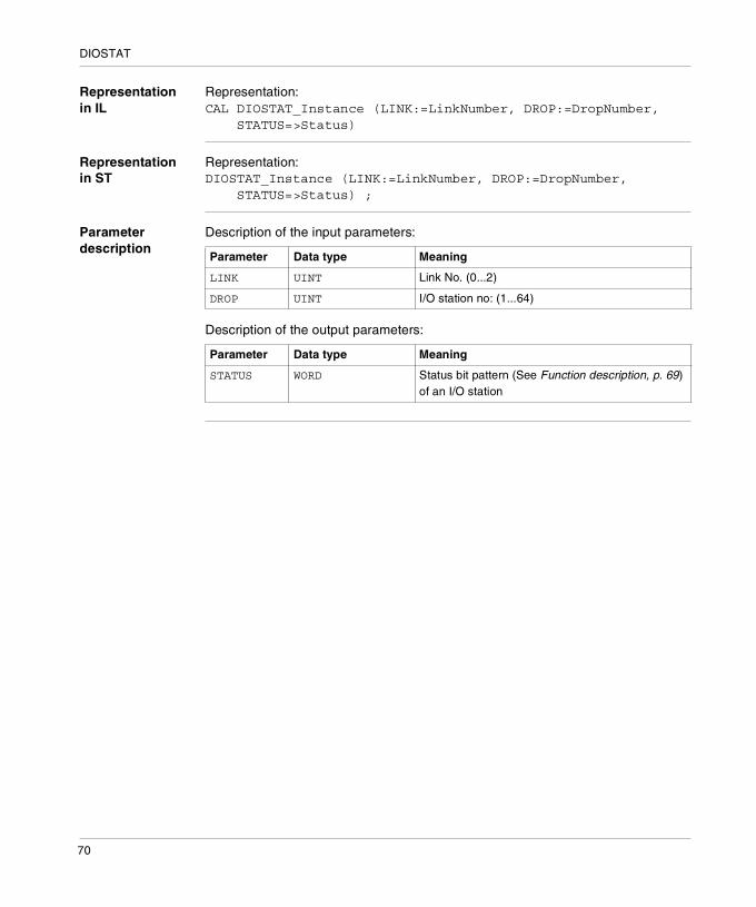
Representation in IL
Representation:CAL DIOSTAT_Instance (LINK:=LinkNumber, DROP:=DropNumber, STATUS=>Status)
Representation in ST
Representation:DIOSTAT_Instance (LINK:=LinkNumber, DROP:=DropNumber, STATUS=>Status) ;
Parameter description
Description of the input parameters:
Description of the output parameters:
Parameter Data type Meaning
LINK UINT Link No. (0...2)
DROP UINT I/O station no: (1...64)
Parameter Data type Meaning
STATUS WORD Status bit pattern (See Function description, p. 69) of an I/O station
70

8
RIOSTAT: Module function status (RIO)Description
Function description
This function block provides the function status for I/O modules of an I/O station (local/remote I/O).Quantum I/O or 800 I/O can be used.An output STATUSx is allocated to each rack. Each module (slot) of this rack is characterized by a bit of the corresponding STATUSx output. The bit on the far left-hand side in STATUSx corresponds to the slot on the far left-hand side of the rack x.Using STATUS1 to STATUS5:� Quantum I/O
There is only one rack for an I/O station, e.g. only STATUS1 is used.� 800 I/O
There can be up to 5 racks for an I/O station, e.g. STATUS1 corresponds to module rack 1, STATUS5 corresponds to module rack 5.
EN and ENO can be configured as additional parameters.
Representation in FBD
Representation:
Note: If a module on the module rack has been configured and works correctly, the corresponding bit is set to "1".
StatusBitPatternRack1
RIOSTAT
Local_RemoteDropNo
StatusBitPatternRack2StatusBitPatternRack3
StatusBitPatternRack4
StatusBitPatternRack5
RIOSTAT_Instance
STATUS1
STATUS2
STATUS3
STATUS4
STATUS5
DROP
71

RIOSTAT
Representation in LD
Representation:
Representation in IL
Representation:CAL RIOSTAT_Instance (DROP:=Local_RemoteDropNo, STATUS1=>StatusBitPatternRack1, STATUS2=>StatusBitPatternRack2, STATUS3=>StatusBitPatternRack3, STATUS4=>StatusBitPatternRack4, STATUS5=>StatusBitPatternRack5)
Representation in ST
Representation:RIOSTAT_Instance (DROP:=Local_RemoteDropNo, STATUS1=>StatusBitPatternRack1, STATUS2=>StatusBitPatternRack2, STATUS3=>StatusBitPatternRack3, STATUS4=>StatusBitPatternRack4, STATUS5=>StatusBitPatternRack5) ;
StatusBitPatternRack1
StatusBitPatternRack2
StatusBitPatternRack3
StatusBitPatternRack4
StatusBitPatternRack5
ENOEN
RIOSTAT
STATUS1
STATUS2
STATUS3
STATUS4
STATUS5
DROP
RIOSTAT_Instance
Local_RemoteDropNo
72

RIOSTAT
Parameter description
Description of the input parameters:
Description of the output parameters:
Parameters Data type Meaning
DROP UINT Local/remote I/O station no. (1...32)
Parameters Data type Meaning
STATUS1 WORD Module rack 1 status bit pattern
STATUS2 WORD Module rack 2 status bit pattern (800 I/O only)
... ... ...
STATUS5 WORD Module rack 5 status bit pattern (800 I/O only)
73

RIOSTAT
74

9
READREG: Read registerOverview
Introduction This chapter describes the READREG block.
What's in this Chapter?
This chapter contains the following topics:
Topic Page
Description 76
Mode of Functioning 79
Parameter description 79
75
READREG
Description
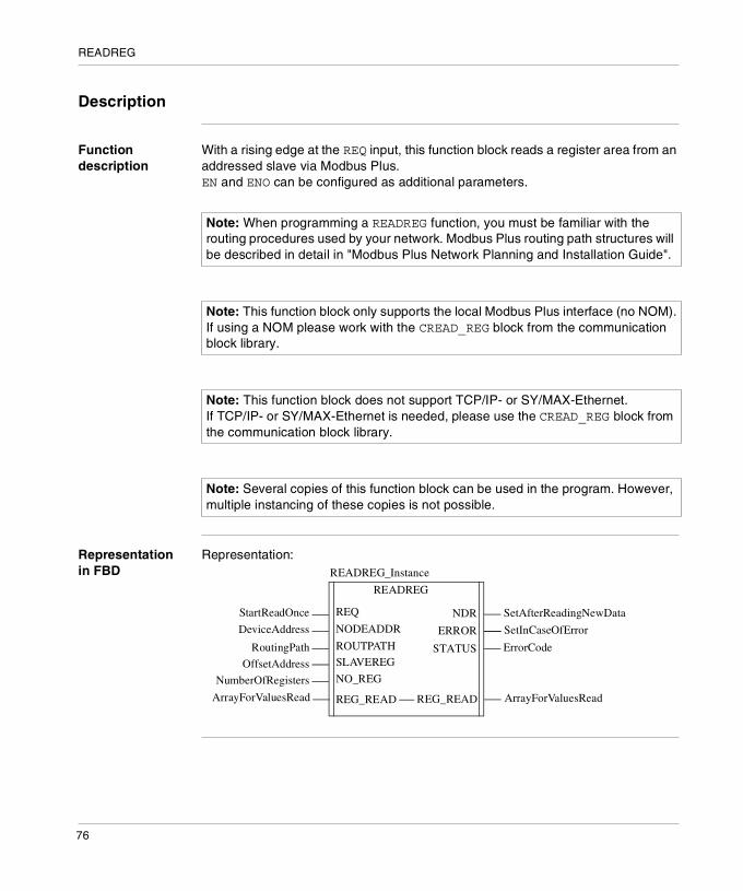
Function description
With a rising edge at the REQ input, this function block reads a register area from an addressed slave via Modbus Plus.EN and ENO can be configured as additional parameters.
Representation in FBD
Representation:
Note: When programming a READREG function, you must be familiar with the routing procedures used by your network. Modbus Plus routing path structures will be described in detail in "Modbus Plus Network Planning and Installation Guide".
Note: This function block only supports the local Modbus Plus interface (no NOM).If using a NOM please work with the CREAD_REG block from the communication block library.
Note: This function block does not support TCP/IP- or SY/MAX-Ethernet. If TCP/IP- or SY/MAX-Ethernet is needed, please use the CREAD_REG block from the communication block library.
Note: Several copies of this function block can be used in the program. However, multiple instancing of these copies is not possible.
SetAfterReadingNewData
READREG
StartReadOnce
SetInCaseOfError
READREG_Instance
NDRREQ
DeviceAddress
RoutingPath
OffsetAddress
NumberOfRegisters
NODEADDR
ROUTPATHSLAVEREG
NO_REG
ErrorCode
ERROR
STATUS
ArrayForValuesReadREG_READREG_READArrayForValuesRead
76

READREG
Representation in LD
Representation:
Representation in IL
Representation:CAL READREG_Instance (REQ:=StartReadOnce, NODEADDR:=DeviceAddress, ROUTPATH:=RoutingPath, SLAVEREG:=OffsetAddress, NO_REG:=NumberOfRegisters, REG_READ:=ArrayForValuesRead, NDR=>SetAfterReadingNewData, ERROR=>SetInCaseOfError, STATUS=>ErrorCode)
Representation in ST
Representation:READREG_Instance (REQ:=StartReadOnce, NODEADDR:=DeviceAddress, ROUTPATH:=RoutingPath, SLAVEREG:=OffsetAddress, NO_REG:=NumberOfRegisters, REG_READ:=ArrayForValuesRead, NDR=>SetAfterReadingNewData, ERROR=>SetInCaseOfError, STATUS=>ErrorCode;
ENOEN
READREGREADREG_Instance
OffsetAddress
NumberOfRegisters
NODEADDR
ROUTPATH
SLAVEREG
NO_REG
DeviceAddress
RoutingPath
StartReadOnceREQ
ErrorCodeSTATUS
SetAfterReadingNewData
SetInCaseOfError
NDR
ERROR
ArrayForValuesReadREG_READREG_READArrayForValuesRead
77

READREG
Parameter description
Description of the input parameters:
Description of input / output parameters:
Description of the output parameters:
Parameter Data type Meaning
REQ BOOL With a rising edge at the REQ input, this function block reads a register area from an addressed slave via Modbus Plus.
NODEADDR INT Device address within the target segment
ROUTPATH DINT Routing path to target segment
SLAVEREG DINT Offset address of the first 4x register in the slave to be read from
NO_REG INT Number of registers to be read from slave
Parameters Data type Meaning
REG_READ ANY_ARRAY_WORD Writing data(For the file to be read a data structure must be declared as a located variable.)
Parameters Data type Meaning
NDR BOOL Set to "1" for one cycle after reading new data
ERROR BOOL Set to "1" for one scan in case of error
STATUS WORD Error Code
78

READREG
Mode of Functioning
Function mode of READREG_DFB blocks
Although a large number of READREG function blocks can be programmed, only four read operations may be active at the same time. It makes no difference whether these operations are performed using this function block or others (e.g. MBP_MSTR, CREAD_REG). All function blocks use one data transaction path and require multiple cycles to complete a task. The status signals NDR and ERROR report the function block state to the user program.The complete routing information must be separated into two parts:� in the NODEADDR of the destination node (regardless of whether it is located in the
local segment or in another segment) and � the routing path, in case there is a link via bridges. The resulting destination address consists of these two information components.The routing path is a DINT data type, which is interpreted as a sequence of two-digit information units. It is not necessary to use "00" extensions (e.g. both routing paths 4711 and 47110000 are valid, for NODEADDR 34 the result is destination address 47.11.34.00.00).
Parameter description
REQ A rising edge triggers the read transaction.The parameter can be specified as an address, located variable, unlocated variable or literal.
NODEADDR Identifies the node address within the target segment.The parameter can be specified as an address, located variable, unlocated variable or literal.
ROUTPATH Identifies the routing path to the target segment. The two-digit information units run from 01 64 (see Mode of Functioning, p. 79). If the slave resides in the local network segment, ROUTPATH must be set to "0" or must be left unconnected.The parameter can be specified as an address, located variable, unlocated variable or literal.
SLAVEREG Start of the area in the addressed slave from which the source data is read. The source area always resides within the 4x register area. SLAVEREG expects the source reference as offset within the 4x area. The leading "4" must be omitted (e.g. 59 (contents of the variables or value of the literal) = 40059).The parameter can be specified as an address, located variable, unlocated variable or literal.
79

READREG
NO_REG Number of registers to be read from slave processor (1 ... 100).The parameter can be specified as an address, located variable, unlocated variable or literal.
NDR Transition to ON state for one program cycle signifies receipt of new data ready to be processed.The parameter can be specified as an address, located variable or unlocated variable.
ERROR Transition to ON state for one program cycle signifies detection of a new error.The parameter can be specified as an address, located variable or unlocated variable.
STATUS Error code, see Modbus Plus Error Codes, p. 87The parameter can be specified as an address, located variable or unlocated variable.
REG_READ An ANY_ARRAY_WORD that is the same size as the requested transmission must be agreed upon (≥ NO_REG) for this parameter. The name of this array is defined as a parameter. If the array is defined too small, then only the amount of data is transmitted that is present in the array.The parameter must be defined as a located variable.
80

10
CREADREG: Continuous register readingOverview
Introduction This chapter describes the CREADREG block.
What's in this Chapter?
This chapter contains the following topics:
Topic Page
Description 82
Mode of Functioning 85
Parameter description 85
Modbus Plus Error Codes 87
81

CREADREG
Description
Function description
This derived function block reads the register area continuously. It reads data from addressed nodes via Modbus Plus.EN and ENO can be configured as additional parameters.
Representation in FBD
Representation:
Note: It is necessary to be familiar with the routing procedures of your network when programming a CREADREG function. Modbus Plus routing path structures will be described in detail in "Modbus Plus Network Planning and Installation Guide".
Note: This function block only supports the local Modbus Plus interface (no NOM).If using a NOM please work with the block CREAD_REG from the communication block library.
Note: This function block does not support TCP/IP- or SY/MAX-Ethernet. If TCP/IP- or SY/MAX-Ethernet is needed, please use the block CREAD_REG of the communication block library.
Note: Several copies of this function block can be used in the program. However, multiple instancing of these copies is not possible.
ErrorCode
CREADREG
DeviceAddress
RoutingPath
OffsetAddress
NumberOfRegisters
CREADREG_Instance
STATUSNODEADDR
ROUTPATHSLAVEREG
NO_REG
ArrayForValuesReadREG_READREG_READArrayForValuesRead
82

CREADREG
Representation in LD
Representation:
Representation in IL
Representation:CAL CREADREG_Instance (NODEADDR:=DeviceAddress, ROUTPATH:=RoutingPath, SLAVEREG:=OffsetAddress, NO_REG:=NumberOfRegisters, REG_READ:=ArrayForValuesRead, STATUS=>ErrorCode)
Representation in ST
Representation:CREADREG_Instance (NODEADDR:=DeviceAddress, ROUTPATH:=RoutingPath, SLAVEREG:=OffsetAddress, NO_REG:=NumberOfRegisters, REG_READ:=ArrayForValuesRead, STATUS=>ErrorCode;
ErrorCode
OffsetAddress
NumberOfRegisters
ENOEN
CREADREG
STATUSNODEADDR
ROUTPATH
SLAVEREG
NO_REG
CREADREG_Instance
DeviceAddress
RoutingPath
ArrayForValuesReadREG_READREG_READArrayForValuesRead
83

CREADREG
Parameter description
Description of the input parameters:
Description of input / output parameters:
Description of the output parameters:
Parameters Data type Meaning
NODEADDR INT Device address within the target segment
ROUTPATH DINT Routing path to target segment
SLAVEREG DINT Offset address of the first 4x register in the slave to be read from
NO_REG INT Number of registers to be read from slave
Parameters Data type Meaning
REG_READ ANY_ARRAY_WORD Writing data(For the file to be read a data structure must be declared as a located variable.)
Parameters Data type Meaning
STATUS WORD Error Code
84

CREADREG
Mode of Functioning
Function mode of CREADREG blocks
Although a large number of CREADREG function blocks can be programmed, only four read operations may be active at the same time. It makes no difference whether these operations are performed using this function block or others (e.g. MBP_MSTR, READREG). All function blocks use one data transaction path and require multiple cycles to complete a task. The complete routing information must be separated into two parts:� in the NODEADDR of the destination node (regardless of whether it is located in the
local segment or in another segment) and � the routing path, in case there is a link via network bridges.The resulting destination address consists of these two information components.The routing path is a DINT data type, which is interpreted as a sequence of two-digit information units. It is not necessary to use "00" extensions (e.g. both routing paths 4711 and 47110000 are valid, for NODEADDR 34 the result is destination address 47.11.34.00.00).
Parameter description
NODEADDR Identifies the node address within the target segment.The parameter can be entered as an address, located variable, unlocated variable or literal.
ROUTPATH Identifies the routing path to the target segment. The two-digit information units run from 01 64 (see Mode of Functioning, p. 85). If the slave resides in the local network segment, ROUTPATH must be set to "0" or must be left unconnected.The parameter can be entered as an address, located variable, unlocated variable or literal.
Note: This function block puts a heavy load on the network. The network load must therefore be carefully monitored. If the network load is too high, the program logic should be reorganized to work with the READREG function block, which is a variant of this function block that does not operate in continuous mode, but is command driven.
85

CREADREG
SLAVEREG Start of the area in the addressed slave from which the source data are read. The source area always resides within the 4x register area. SLAVEREG expects the source reference as offset within the 4x area. The leading "4" must be omitted (e.g. 59 (contents of the variables or value of the literal) = 40059).The parameter can be entered as an address, located variable, unlocated variable or literal.
NO_REG Number of registers to be read from slave processor (1 ... 100).The parameter can be entered as an address, located variable, unlocated variable or literal.
STATUS Error code, see Modbus Plus Error Codes, p. 87The parameter can be specified as an address, located variable or unlocated variable.
REG_READ An ANY_ARRAY_WORD that is the same size as the requested transmission must be agreed upon (≥ NO_REG) for this parameter. The name of this array is defined as a parameter. If the array is defined too small, then only the amount of data is transmitted that is present in the array.The parameter must be defined as a located variable.
86

CREADREG
Modbus Plus Error Codes
Form of the function error code
The form of the function error code for Modbus Plus is Mmss, which includes:� M is the high code� m is the low code� ss is a subcode
Hexadecimal error code
Hexadecimal error code for Modbus Plus:
Hex. Error Code
Meaning
1001 Abort by user
2001 An operation type that is not supported was specified in the control block
2002 One or more control block parameters were modified while the MSTR element was active (this only applies to operations which require several cycles for completion). Control block parameters my only be modified in inactive MSTR components.
2003 Illegal value in the length field of the control block
2004 Illegal value in the offset field of the control block
2005 Illegal value in the length and offset fields of the control block
2006 Unauthorized data field on slave
2007 Unauthorized network field on slave
2008 Unauthorized network routing path on slave
2009 Routing path equivalent to own address
200A Attempting to retrieve more global data words than available
30ss Unusual response by Modbus slave (See ss hexadecimal value in 30ss error code, p. 88)
4001 Inconsistent response by Modbus slave
5001 Inconsistent response by network
6mss Routing path error (See ss hexadecimal value in 6mss error code, p. 88)Subfield m shows where the error occurred (a 0 value means local node, 2 means 2nd device in route, etc) .
87

CREADREG
ss hexadecimal value in 30ss error code
ss hexadecimal value in 30ss error code:
ss hexadecimal value in 6mss error code
The ss subfield in error code 6mss is as follows:
ss hex. Value Meaning
01 Slave does not support requested operation
02 Non-existent slave registers were requested
03 An unauthorized data value was requested
05 Slave has accepted a lengthy program command
06 Function cannot currently be carried out: lengthy command running
07 Slave has rejected lengthy program command
Note: Subfield m in error code 6mss is an Index in the routing information that shows where an error has been detected (a 0 value indicates the local node, 2 means the second device in the route, etc.).
ss hex. Value Meaning
01 No response receipt
02 Access to program denied
03 Node out of service and unable to communicate
04 Unusual response received
05 Router-node data path busy
06 Slave out of order
07 Wrong destination address
08 Unauthorized node type in routing path
10 Slave has rejected the command
20 Slave has lost an activated transaction
40 Unexpected master output path received
80 Unexpected response received
F001 Wrong destination node specified for MSTR operation
88

11
WRITEREG: Write registerOverview
Introduction This chapter describes the WRITEREG block.
What's in this Chapter?
This chapter contains the following topics:
Topic Page
Description 90
Mode of Functioning 93
Parameter description 93
89

WRITEREG
Description
Function description
With a rising edge at the REQ input, this function block writes a register area from the PLC to an addressed slave via Modbus Plus.EN and ENO can be configured as additional parameters.
Representation in FBD
Representation:
Note: When programming a WRITEREG function, you must be familiar with the routing procedures used by your network. Modbus Plus routing path structures will be described in detail in "Modbus Plus Network Planning and Installation Guide".
Note: This derived function block only supports the local Modbus Plus interface (no NOM).If using a NOM please work with the WRITE_REG block from the communication block library.
Note: This derived function block also does not support TCP/IP- or SY/MAX-Ethernet. If TCP/IP- or SY/MAX-Ethernet is needed, please use the WRITE_REG block from the communication block library.
Note: Several copies of this function block can be used in the program. However, multiple instancing of these copies is not possible.
SetAfterWritingData
WRITEREG
StartWriteOnce
SetInCaseOfError
WRITEREG_Instance
DONEREQ
DeviceAddress
RoutingPath
OffsetAddress
NumberOfRegisters
NODEADDR
ROUTPATHSLAVEREG
NO_REG
ErrorCode
ERROR
STATUS
SourceDataArea REG_WRIT SourceDataAreaREG_WRIT
90

WRITEREG
Representation in LD
Representation:
Representation in IL
Representation:CAL WRITEREG_Instance (REQ:=StartWriteOnce, NODEADDR:=DeviceAddress, ROUTPATH:=RoutingPath, SLAVEREG:=OffsetAddress, NO_REG:=NumberOfRegisters, REG_WRIT:=SourceDataArea, DONE=>SetAfterWritingData,ERROR=>SetInCaseOfError, STATUS=>ErrorCode)
Representation in ST
Representation:WRITEREG_Instance (REQ:=StartWriteOnce, NODEADDR:=DeviceAddress, ROUTPATH:=RoutingPath, SLAVEREG:=OffsetAddress, NO_REG:=NumberOfRegisters, REG_WRIT:=SourceDataArea, DONE=>SetAfterWritingData,ERROR=>SetInCaseOfError, STATUS=>ErrorCode) ;
ENOEN
WRITEREGWRITEREG_Instance
OffsetAddress
NumberOfRegisters
NODEADDR
ROUTPATH
SLAVEREG
NO_REG
DeviceAddress
RoutingPath
StartWriteOnceREQ
ErrorCodeSTATUS
SetAfterWritingData
SetInCaseOfError
DONE
ERROR
SourceDataArea REG_WRIT SourceDataAreaREG_WRIT
91

WRITEREG
Parameter description
Description of input parameters:
Description of input / output parameters:
Description of the output parameters:
Parameter Data type Meaning
REQ BOOL With a rising edge at the REQ input, this function block writes a register area from the PLC to an addressed slave via Modbus Plus.
NODEADDR INT Device address within the target segment
ROUTPATH DINT Routing path to target segment
SLAVEREG DINT Offset address of the first 4x register in the slave to be written to
NO_REG INT Number of registers to be written from slave
Parameters Data type Meaning
REG_WRIT ANY_ARRAY_WORD Source data field(A data structure must be declared as a located variable for the source file.)
Parameters Data type Meaning
DONE BOOL Set to "1" for one scan after writing data
ERROR BOOL Set to "1" for one scan in case of error
STATUS WORD Error Code
92

WRITEREG
Mode of Functioning
Function mode of WRITEREG blocks
Although a large number of WRITEREG function blocks can be programmed, only four write operations may be active at the same time. It makes no difference whether these operations are performed using this function block or others (e.g. MBP_MSTR, CWRITE_REG). All function blocks use one data transaction path and require multiple cycles to complete a task. If several WRITEREG function blocks are used within an application, they must at least differ in the values of their NO_REG or REG_WRIT parameters.
The status signals DONE and ERROR report the function block state to the user program.
The complete routing information must be separated into two parts:� in the NODEADDR of the destination node (regardless of whether it is located in the
local segment or in another segment) and � the routing path, in case there is a link via network bridges.The resulting destination address consists of these two information components.The routing path is a DINT data type, which is interpreted as a sequence of two-digit information units. It is not necessary to use "00" extensions (e.g. both routing paths 4711 and 47110000 are valid, for NODEADDR 34 the result is destination address 47.11.34.00.00).
Parameter description
REQ A rising edge triggers the write transaction.The parameter can be entered as an address, located variable, unlocated variable or literal.
NODEADDR Identifies the node address within the target segment.The parameter can be entered as an address, located variable, unlocated variable or literal.
ROUTPATH Identifies the routing path to the target segment. The two-digit information units run from 01 64 (see Mode of Functioning, p. 93). If the slave resides in the local network segment, ROUTPATH must be set to "0" or must be left unconnected.The parameter can be entered as an address, located variable, unlocated variable or literal.
93

WRITEREG
SLAVEREG Start of the destination area in the addressed slave to which the source data is written. The destination area always resides within the 4x register area. SLAVEREG expects the destination address as an offset within the 4x area. The leading "4" must be omitted (e.g. 59 (contents of the variables or value of the literal) = 40059).The parameter can be entered as an address, located variable, unlocated variable or literal.
NO_REG Number of registers to be written to slave processor (1 ... 100).The parameter can be entered as an address, located variable, unlocated variable or literal.
REG_WRIT An ANY_ARRAY_WORD that is the same size as the planned transmission must be agreed upon (≥ NO_REG) for this parameter. The name of this array is defined as a parameter. If the array is defined too small, then only the amount of data is transmitted that is present in the array.The parameter must be defined as a located variable.
DONE Transition to ON state for one program scan signifies data have been transferred.The parameter can be entered as an address, located variable or unlocated variable.
ERROR Transition to ON state for one program cycle signifies detection of a new error.The parameter can be specified as an address, located variable or unlocated variable.
STATUS Error code, see Modbus Plus Error Codes, p. 87The parameter can be specified as an address, located variable or unlocated variable.
94

12
CWRITREG: Continuous register writingOverview
Introduction This chapter describes the CWRITREG block.
What's in this Chapter?
This chapter contains the following topics:
Topic Page
Description 96
Mode of Functioning 99
Parameter description 100
95

CWRITEREG
Description
Function description
This derived function block writes continuously to the register area. It transfers data from the PLC via Modbus Plus to a specified slave destination processor.EN and ENO can be configured as additional parameters.
Representation in FBD
Representation:
Note: When programming a CWRITREG function, you must be familiar with the routing procedures used by your network. Modbus Plus routing path structures will be described in detail in "Modbus Plus Network Planning and Installation Guide".
Note: This function block only supports the local Modbus Plus interface (no NOM).If using a NOM please work with the CWRITE_REG block from the communication block library.
Note: This function block does not support TCP/IP- or SY/MAX-Ethernet. If TCP/IP- or SY/MAX-Ethernet is needed, please use the CWRITE_REG block from the communication block library.
Note: Several copies of this function block can be used in the program. However, multiple instancing of these copies is not possible.
ErrorCode
CWRITREG
DeviceAddress
RoutingPath
OffsetAddress
NumberOfRegisters
SourceDataArea
CWRITREG_Instance
STATUSNODEADDR
ROUTPATHSLAVEREG
NO_REG
REG_WRIT REG_WRIT SourceDataArea
96

CWRITEREG
Representation in LD
Representation:
Representation in IL
Representation:CAL CWRITREG_Instance (NODEADDR:=DeviceAddress, ROUTPATH:=RoutingPath, SLAVEREG:=OffsetAddress, NO_REG:=NumberOfRegisters, REG_WRIT:=SourceDataArea, STATUS=>ErrorCode)
Representation in ST
Representation:CWRITREG_Instance (NODEADDR:=DeviceAddress, ROUTPATH:=RoutingPath, SLAVEREG:=OffsetAddress, NO_REG:=NumberOfRegisters, REG_WRIT:=SourceDataArea, STATUS=>ErrorCode) ;
ErrorCode
OffsetAddress
NumberOfRegisters
ENOEN
CWRITREG
STATUSNODEADDR
ROUTPATH
SLAVEREG
NO_REG
CWRITREG_Instance
DeviceAddress
SourceDataArea
RoutingPath
REG_WRIT REG_WRIT SourceDataArea
97

CWRITEREG
Parameter description
Description of the input parameters:
Description of input / output parameters:
Description of the output parameters:
Parameters Data type Meaning
NODEADDR INT Device address within the target segment
ROUTPATH DINT Routing path to target segment
SLAVEREG DINT Offset address of the first 4x register in the slave to be written to
NO_REG INT Number of registers to be written from slave
Parameters Data type Meaning
REG_WRIT ANY_ARRAY_WORD Source data field(A data structure must be declared as a located variable for the source file.)
Parameters Data type Meaning
STATUS WORD Error Code
98

CWRITEREG
Mode of Functioning
Function mode of CWRITREG blocks
Although an unlimited number of CWRITREG function blocks can be programmed, only four write operations may be active at the same time. It makes no difference whether these operations are performed using this function block or others (e.g. MBP_MSTR, WRITEREG). All function blocks use one data transaction path and require multiple cycles to complete a task.If several CWRITREG function blocks are used within an application, they must at least differ in the values of their NO_REG or REG_WRIT parameters.
The complete routing information must be separated into two parts:� in the NODEADDR of the destination node (regardless of whether it is located in the
local segment or in another segment) and � the routing path, in case there is a link via network bridges.The resulting destination address consists of these two information components.The routing path is a DINT data type, which is interpreted as a sequence of two-digit information units. It is not necessary to use "00" extensions (e.g. both routing paths 4711 and 47110000 are valid, for NODEADDR 34 the result is destination address 47.11.34.00.00).
Note: This function block puts a heavy load on the network. The network load must therefore be carefully monitored. If the network load is too high, the program logic should be reorganized to work with the WRITEREG function block, which is a variant of this function block that does not operate in continuous mode, but is command driven.
99

CWRITEREG
Parameter description
NODEADDR Identifies the node address within the target segment.The parameter can be specified as an address, located variable, unlocated variable or literal.
ROUTPATH Identifies the routing path to the target segment. The two-digit information units run from 01 64 (see Mode of Functioning, p. 99). If the slave resides in the local network segment, ROUTPATH must be set to "0" or must be left unconnected.The parameter can be specified as an address, located variable, unlocated variable or literal.
SLAVEREG Start of the destination area in the addressed slave to which the source data are written. The destination area always resides within the 4x register area. SLAVEREG expects the destination address as an offset within the 4x area. The leading "4" must be omitted (e.g. 59 (contents of the variables or value of the literal) = 40059).The parameter can be entered as an address, located variable, unlocated variable or literal.
NO_REG Number of registers to be written to slave processor (1 ... 100).The parameter can be specified as an address, located variable, unlocated variable or literal.
REG_WRIT An ANY_ARRAY_WORD that is the same size as the planned transmission must be agreed upon (≥ NO_REG) for this parameter. The name of this array is defined as a parameter. If the array is defined too small, then only the amount of data is transmitted that is present in the array.The parameter must be defined as a located variable.
STATUS If MSTR error code is returned, see Modbus Plus Error Codes, p. 87The parameter can be specified as an address, located variable or unlocated variable.
100
13
LOOKUP_TABLE1_DFB: Traverse progression with 1st degree interpolationOverview
Introduction This chapter describes the LOOKUP_TABLE1_DFB block.
What's in this Chapter?
This chapter contains the following topics:
Topic Page
Description 102
Detailed description 103
101

LOOKUP_TABLE1_DFB
Description
Function description
This function block linearizes characteristic curves by means of interpolation. The function block works with variable support point width.The number of XiYi inputs can be increased to 30 by modifying the size of the block frame vertically. This corresponds to a maximum of 15 support point pairs. The number of inputs must be even.The X values must be in ascending order.EN and ENO can be configured as additional parameters.
Representation in FBD
Representation:
Representation in LD
Representation:
Representation in IL
Representation:CAL LOOKUP_TABLE1_DFB_Instance (X:=InputVariable, XiYi1:=X_Coord_1_SupportPoint, XiYi2:=Y_Coord_1_SupportPoint, Y=>OutputVariable, QXHI=>IndicatorSignalX>Xm, QXLO=>IndicatorSignalX<X1)
OutputVariable
LOOKUP_TABLE1_DFB
InputVariable
X_Coord_1_SupportPoint
Y_Coord_1_SupportPoint
IndicatorSignalX>XmIndicatorSignalX<X1
LOOKUP_TABLE1_DFB_Instance
Y
QXHI
QXLO
X
XiYi1XiYi2
OutputVariable
Y_Coord_1_SupportPoint
ENOEN
LOOKUP_TABLE1_DFB
YX
XiYi1
XiYi2
LOOKUP_TABLE1_DFB_Instance
InputVariable
X_Coord_1_SupportPointIndicatorSignalX>Xm
QXHIIndicatorSignalX<X1
QXLO
102

LOOKUP_TABLE1_DFB
Representation in ST
Representation:LOOKUP_TABLE1_DFB_Instance (X:=InputVariable, XiYi1:=X_Coord_1_SupportPoint, XiYi2:=Y_Coord_1_SupportPoint, Y=>OutputVariable, QXHI=>IndicatorSignalX>Xm, QXLO=>IndicatorSignalX<X1) ;
Parameter description
Description of the input parameters:
Description of the output parameters:
Detailed description
Parameter description
Each two sequential inputs (XiYi) represent a support point pair. The first input XiYi corresponds to X1, the next one to Y1, the one after that to X2, etc.For all types of input value in X found between these support points, the corresponding Y output value is interpolated, while the traverse progression between the support points is viewed linearly.For X < X1 is Y = Y1For X > Xm is Y = Ym
If the value at input X is higher than the value of the last support point Xm, the output QXHI becomes "1".If the value at input X is less than the value of the first support point X1, the output QXLO becomes "1".
Parameter Data type Meaning
XiYi1 REAL X coordinate 1. Support point
XiYi2 REAL Y coordinate 1. Support point
XiYin REAL X coordinate m/2. Support point
XiYim REAL Y coordinate m/2. Support point
X REAL Input variable
Parameter Data type Meaning
Y REAL Output variable
QXHI BOOL Indicator: X > Xm
QXLO BOOL Indicate X < X1
103

LOOKUP_TABLE1_DFB
Principle of interpolation
Traverse progression with 1st degree interpolation)
Interpolation The following algorithm applies to a point Y:
for Xi ≤ X ≤ Xi+1 and i = 1 ... (m-1)Assuming: X1 ≤ X2 ≤ ... ≤ Xi ≤ Xi+1 ≤ ... ≤ Xm-1 ≤ Xm
The X values must be in ascending order.Two consecutive X values can be identical. This could cause a discrete curve progression.In this instance, the special case applies:Y = 0.5 x (Yi + Yi+1)for Xi = X = Xi+1 and i = 1 ... (m-1)
Y
0 X
Ym
Yi+1Ym-1Y
Yi
Xi X Xi+1 Xm-1Xm
Y YiYi 1 Yi–+
Xi 1 Xi–+---------------------------- X Xi–( )×+=
104

14
PLCSTAT: PLC function statusOverview
Introduction This chapter describes the PLCSTAT block.
What's in this Chapter?
This chapter contains the following topics:
Topic Page
Description 106
Derived Data Types 108
PLC status (PLC_STAT) 110
RIO status (RIO_STAT) for Quantum 112
DIO status (DIO_STAT) 114
105

PLCSTAT
Description
Function description
This derived function block reads the Quantum PLC internal states and error bits and copies this data to the data structures allocated to the respective outputs.
EN and ENO can be configured as additional parameters.Only data with the input bit (PLC_READ, RIO_READ, DIO_READ) set to "1" will be read.
Evaluation The evaluation of PLC_STAT (PLC status), RIO_STAT (I/O status) and DIO_STAT (I/O communications status) is possible.
Representation in FBD
Representation:
Representation in LD
Representation:
Note: The name of the output DIO_STAT is confusing. This output only relates to the remote I/O Drop Status Information (S908) and not to the Distributed I/O status. To read the distributed I/O status use the function block DIOSTAT (See DIOSTAT: Module function status (DIO), p. 69).
PLC_IO_Status
PLCSTAT
CopyPLCStatusFlag
CopyRIOStatusFlag
CopyDIOStatusFlag
RIO_IO_Status
DIO_IO_Status
PLCSTAT_Instance
PLC_STAT
RIO_STAT
DIO_STAT
PLC_READ
RIO_READ
DIO_READ
CopyDIOStatusFlag
CopyRIOStatusFlag
CopyPLCStatusFlag
ENO
PLCSTAT
PLC_STATPLC_READ
RIO_READ
DIO_READ
PLCSTAT_Instance
PLC_IO_Status
RIO_IO_Status
DIO_IO_Status
RIO_STAT
DIO_STAT
EN
106

PLCSTAT
Representation in IL
Representation:CAL PLCSTAT_Instance (PLC_READ:=CopyPLCStatusFlag, RIO_READ:=CopyRIOStatusFlag, DIO_READ:=CopyDIOStatusFlag, PLC_STAT=>PLC_IO_Status, RIO_STAT=>RIO_IO_Status, DIO_STAT=>DIO_IO_Status)
Representation in ST
Representation:PLCSTAT_Instance (PLC_READ:=CopyPLCStatusFlag, RIO_READ:=CopyRIOStatusFlag, DIO_READ:=CopyDIOStatusFlag, PLC_STAT=>PLC_IO_Status, RIO_STAT=>RIO_IO_Status, DIO_STAT=>DIO_IO_Status) ;
PLCSTAT parameter description
Description of the input parameters:
Description of the output parameters:
Parameters Data type Meaning
PLC_READ BOOL 1 = copies the PLC status from the status table to the output PLC_STAT.
RIO_READ BOOL 1 = copies the RIO status from the status table to the output RIO_STAT.
DIO_READ BOOL 1 = copies the DIO status from the status table to the output DIO_STAT.
Parameters Data type Meaning
PLC_STAT PLCSTATE, Contains the PLC status.
RIO_STAT RIOSTATE, Contains the RIO status (I/O status) for Quantum
DIO_STAT DIOSTATE, Contains the DIO status (I/O communication status)Note: The name of this output is confusing. This output only relates to the remote I/O Drop Status Information (S908) and not to the Distributed I/O status. To read the distributed I/O status use the function block DIOSTAT (See DIOSTAT: Module function status (DIO), p. 69).
107

PLCSTAT
Derived Data Types
Element description PLCSTATE
Description of the PLCSTATE element:
Element description RIOSTATE
Description of the RIOSTATE element
Element Data type Meaning
word1 WORD CPU status
word2 WORD Hot Standby Status
word3 WORD PLC status
word4 WORD RIO Status
word5 WORD Reserve
word6 WORD Reserve
word7 WORD Reserve
word8 WORD Reserve
word9 WORD Reserve
word10 WORD Reserve
word11 WORD Reserve
Element Data type Meaning
word1 WORD I/O station 1, module rack 1
word2 WORD I/O station 1, module rack 2
... ... ...
word5 WORD I/O station 1, module rack 5
word6 WORD I/O station 2, module rack 1
word7 WORD I/O station 2, module rack 2
... ... ...
word160 WORD I/O station 32, module rack 5
108

PLCSTAT
Element description DIOSTATE
Description of the DIOSTATE element
Element Data type Meaning
word1 WORD Switch on error numbers:
word2 WORD Cable A error
word3 WORD Cable A error
word4 WORD Cable A error
word5 WORD Cable B error
word6 WORD Cable B error
word7 WORD Cable B error
word8 WORD Global communication status
word9 WORD Global cumulative error counter for cable A
word10 WORD Global cumulative error counter for cable B
word11 WORD I/O station 1 health status and repetition counter (first word)
word12 WORD I/O station 1 health status and repetition counter (second word)
word13 WORD I/O station 1 health status and repetition counter (third word)
word14 WORD I/O station 2 health status and repetition counter (first word)
... ... ...
word104 WORD I/O station 32 health status and repetition counter (first word)
word105 WORD I/O station 32 health status and repetition counter (second word)
word106 WORD I/O station 32 health status and repetition counter (third word)
109

PLCSTAT
PLC status (PLC_STAT)
General information
The conditions are true when the bits are set to 1.
PLC status (PLCSTATE: word1)
Bit allocation:
Hot Standby status (PLCSTATE: word2)
Bit allocation:
Note: Information corresponds to status table words 1 to 11 in the dialog PLC status.
Bit Allocation
10 Run light OFF
11 Memory protect OFF
12 Battery failed
1 2 3 4 5 6 7 8 9 10 11 12 13 14 15 16
Bit Allocation
1 CHS 110/S911/R911 present and OK
11 0 = CHS shift switch set to A1 = CHS shift switch set to B
12 0 = PLCs have equal logic1 = PLCs have unequal logic
13, 14 Remote system condition
15, 16 Local system condition
1 2 3 4 5 6 7 8 9 10 11 12 13 14 15 16
Dec123
binary0 1 = Offline1 0 = Primary1 1 = Standby
Dec123
binary0 1 = Offline1 0 = Primary1 1 = Standby
110
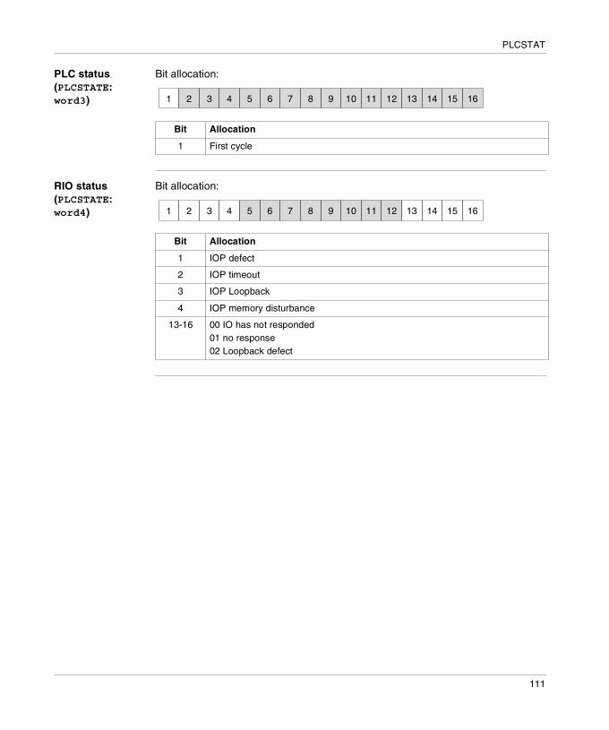
PLCSTAT
PLC status (PLCSTATE: word3)
Bit allocation:
RIO status (PLCSTATE: word4)
Bit allocation:
Bit Allocation
1 First cycle
1 2 3 4 5 6 7 8 9 10 11 12 13 14 15 16
Bit Allocation
1 IOP defect
2 IOP timeout
3 IOP Loopback
4 IOP memory disturbance
13-16 00 IO has not responded01 no response02 Loopback defect
1 2 3 4 5 6 7 8 9 10 11 12 13 14 15 16
111

PLCSTAT
RIO status (RIO_STAT) for Quantum
General information
The words show the I/O module function status.Five words are reserved for each of the maximum 32 I/O stations. Each word corresponds to one of maximal 2 possible module racks in each I/O station.
Function display for Quantum hardware
Each of the module racks for Quantum hardware can contain up to 15 I/O modules (except for the first rack which contains a maximum 14 I/O modules). Bit 1... 16 in each word show the corresponding I/O module function display in the racks.
I/O module function status
Bit allocation:
Conditions for a correct function display
Four conditions must be fulfilled if an I/O module can give a correct function display:� The data traffic of the slot has to be monitored.� The slot must be valid for the inserted module.� Valid communication must be established between the module and the RIO
interface at RIO stations.� Valid communication must be established between the I/O processor in the PLC
and the RIO interface at the RIO station.
Note: The information corresponds to status table words 12 to 171 in the PLC status dialog.
Bit Allocation
1 Slot 1
2 Slot 2
... ...
16 Slot 16
1 2 3 4 5 6 7 8 9 10 11 12 13 14 15 16
112

PLCSTAT
Status words for the MMI user controllers
The status of the 32 element button controllers and PanelMate units in a RIO network can also be monitored with an I/O function status word. The button controllers are located on slot 4 in a I/O rack and can be monitored at bit 4 of the corresponding status word. A PanelMate on RIO is located on slot 1 in module rack 1 of the I/O station and can be monitored at bit 1 of the first status word for the I/O station.
Note: The ASCII keyboard communication status can be monitored with the error numbers in the ASCII read/write instructions.
113
PLCSTAT
DIO status (DIO_STAT)
General information
The words contain the I/O communication status (DIO status) Words 1 to 10 are global status words. Of the remaining 96 words, three words are allocated to each of the up to 32 I/O stations.word1 saves the switch on error numbers. This word is always 0 when the system is running. If an error occurs, the PLC does not start but generates a PLC stop status (word5 from PLC_STAT).The conditions are true when the bits are set to 1.
Note: The information corresponds to status table words 172 to 277 in the PLC status dialog.
114

PLCSTAT
Switch on error numbers (DIOSTATE word1)
The conditions are true when the bits are set to 1.Switch on error numbers:
Code Error Meaning (location of error)
01 BADTCLEN Traffic cop length
02 BADLNKNUM RIO link number
03 BADNUMDPS I/O station number in traffic cop
04 BADTCSUM Traffic cop checksum
10 BADDDLEN I/O station descriptor length
11 BADDRPNUM I/O station number
12 BADHUPTIM I/O station stop time
13 BADASCNUM ASCII port number
14 BADNUMODS Module number in I/O station
15 PRECONDRP I/O station is already configured
16 PRECONPRT Port is already configured
17 TOOMNYOUT More than 1024 output locations
18 TOOMNYINS More than 1024 input points
20 BADSLTNUM Module slot address
21 BADRCKNUM Rack address
22 BADOUTBC Number of output bytes
23 BADINBC Number of input bytes
25 BADRF1MAP First reference number
26 BADRF2MAP Second reference number
27 NOBYTES No input or output bytes
28 BADDISMAP I/O marker bit not at 16 bit limit
30 BADODDOUT Unmated, odd output module
31 BADODDIN Unmated, odd input module
32 BADODDREF Unmated odd module reference
33 BAD3X1XRF 1x-reference after 3x-register
34 BADDMYMOD Dummy module reference already in use
35 NOT3XDMY 3x-module is not a dummy module
36 NOT4XDMY 4x-module is not a dummy module
40 DMYREAL1X Dummy module, then real 1x-module
41 REALDMY1X Real, then 1x-dummy module
42 DMYREAL3X Dummy module, then real 3x-module
43 REALDMY3X Real, then 3x-dummy module
115

PLCSTAT
Status of cable A (DIOSTATE: word2, word3, word4)
Bit allocation for word2:
Bit allocation for word3:
Bit allocation for word4:
Bit Allocation
1 - 8 Counts frame fields
9 - 16 Counts DMA receiver overflows
Bit Allocation
1 - 8 Counts receiver errors
9 - 16 Counts I/O station receiver failures
Bit Allocation
1 1 = frame too short
2 1 = no frame end
13 1 = CRC error
14 1 = alignment error
15 1 = overflow error
1 2 3 4 5 6 7 8 9 10 11 12 13 14 15 16
1 2 3 4 5 6 7 8 9 10 11 12 13 14 15 16
1 2 3 4 5 6 7 8 9 10 11 12 13 14 15 16
116

PLCSTAT
Status of cable B (DIOSTATE: word5, word6, word7)
Bit allocation for word5:
Bit allocation for word6:
Bit allocation for word7:
Bit Allocation
1 - 8 Counts frame fields
9 - 16 Counts DMA receiver overflows
Bit Allocation
1 - 8 Counts receiver errors
9 - 16 Counts I/O station receiver failures
Bit Allocation
1 1 = frame too short
2 1 = no frame end
13 1 = CRC error
14 1 = alignment error
15 1 = overflow error
1 2 3 4 5 6 7 8 9 10 11 12 13 14 15 16
1 2 3 4 5 6 7 8 9 10 11 12 13 14 15 16
1 2 3 4 5 6 7 8 9 10 11 12 13 14 15 16
117

PLCSTAT
Global communication status (DIOSTATE: word8)
The conditions are true when the bits are set to 1.Bit allocation for word8:
Global cumulative error counter for cable A (DIOSTATE: word9)
The conditions are true when the bits are set to 1.Bit allocation for word9:
Global cumulative error counter for cable B(DIOSTATE: word10)
The conditions are true when the bits are set to 1.Bit allocation for word10:
Bit Allocation
1 Comm. function display
2 Cable A status
3 Cable B status
5 - 8 Communication counter lost
9 - 16 Cumulative repetition counter
1 2 3 4 5 6 7 8 9 10 11 12 13 14 15 16
Bit Allocation
1 - 8 Counts recognized errors
9 - 16 Counts zero responses
1 2 3 4 5 6 7 8 9 10 11 12 13 14 15 16
Bit Allocation
1 - 8 Counts recognized errors
9 - 16 Counts zero responses
1 2 3 4 5 6 7 8 9 10 11 12 13 14 15 16
118

PLCSTAT
RIO status (DIOSTATE: word11 to word106)
Words 11 to 106 are used to describe the RIO station status, three status words are planned for each I/O station.The first word in each group of three shows the communication status for the corresponding I/O station:
The second word in each group of three is the cumulative I/O station error counter at cable A for the corresponding I/O station:
The third word in each group of three is the cumulative I/O station error counter at cable B for the corresponding I/O station:
Bit Allocation
1 Communication health
2 Cable A status
3 Cable B status
5 - 8 Counter for lost communications
9 - 16 Cumulative repetition counter
Bit Allocation
1 - 8 Minimum one error in words 2 to 4
9 - 16 Counts zero responses
Bit Allocation
1 - 8 Minimum one error in words 5 to 7
9 - 16 Counts zero responses
Note: For PLCs where the I/O station 1 is reserved for the local I/O, words word11 to word13 are allocated as follows:
1 2 3 4 5 6 7 8 9 10 11 12 13 14 15 16
1 2 3 4 5 6 7 8 9 10 11 12 13 14 15 16
1 2 3 4 5 6 7 8 9 10 11 12 13 14 15 16
119

PLCSTAT
word11 shows the global I/O station status:
word12 is used as a 16 bit I/O bus error counter.word13 is used as a 16 bit I/O repetition counter.
Bit Allocation
1 All modules OK
9 - 16 Counts, how often a module is regarded as not OK, counter overflow is at 255
1 2 3 4 5 6 7 8 9 10 11 12 13 14 15 16
120

15
SET_TOD: Setting the hardware clock (Time Of Day)Description
Function description
This function block searches (together with the other function blocks in the HSBY group) the configuration of the respective PLC for the necessary components. These components always refer to the hardware actually connected.Therefore the correct functioning of this function block on the simulators cannot be guaranteed.The function block sets the hardware system clock, if the corresponding registers are provided within this configuration. If these registers are not present, the TOD_CNF output is set to "0". The function block reads the input values on the S_PULSE input at a rising edge and transfers them to the hardware clock.For all input values:� If the value exceeds the specified maximum value, the maximum is used.� If the value falls below the specified minimum value, the minimum is used.EN and ENO can be configured as additional parameters.
Representation in FBD
Representation:
ClockReady
SET_TOD
InputAcceptedFlag
DayOfWeek
BYTE_variable2
BYTE_variable3
BYTE_variable4
BYTE_variable5
BYTE_variable6
BYTE_variable7
TOD_CNFS_PULSE
D_WEEKMONTH
DAY
YEAR
HOURMINUTE
SECOND
SET_TOD_Instance
121

SET_TOD
Representation in LD
Representation:
Representation in IL
Representation:CAL SET_TOD_Instance (S_PULSE:=InputAcceptedFlag, D_WEEK:=DayOfWeek, MONTH:=Byte_variable2, DAY:=Byte_variable3, YEAR:=Byte_variable4, HOUR:=Byte_variable5, MINUTE:=Byte_variable6, SECOND:=Byte_variable7, TOD_CNF=>ClockReady)
Representation in ST
Representation:SET_TOD_Instance (S_PULSE:=InputAcceptedFlag, D_WEEK:=DayOfWeek, MONTH:=Byte_variable2, DAY:=Byte_variable3, YEAR:=Byte_variable4, HOUR:=Byte_variable5, MINUTE:=Byte_variable6, SECOND:=Byte_variable7, TOD_CNF=>ClockReady) ;
BYTE_variable2
BYTE_variable3
BYTE_variable5
BYTE_variable6
ENOEN
SET_TOD
TOD_CNFS_PULSE
D_WEEK
MONTH
DAY
YEAR
HOUR
MINUTE
SECOND
SET_TOD_Instance
BYTE_variable4
BYTE_variable7
DayOfWeek
InputAcceptedFlag ClockReady
122

SET_TOD
Parameter description
Description of the input parameters:
Description of the output parameters:
Parameters Data type Meaning
S_PULSE BOOL "0 -> 1" = the input values are accepted and written into the clock.
D_WEEK BYTE Day of week, 1 = Sunday 7 = Saturday
MONTH BYTE Month 1..12
DAY BYTE Day 1..31
YEAR BYTE Year 0..99
HOUR BYTE Hour 0..23
MINUTE BYTE Minute 0..59
SECOND BYTE Second 0..59
Parameters Data type Meaning
TOD_CNF BOOL "1" = %MW register (4x) for the hardware system clock was found and the clock is operational."0" = Time is currently being set or hardware clock was not found.
123

SET_TOD
124

16
GET_TOD: Reading the hardware clock (Time Of Day)Description
Function description
This function block searches (together with the other function blocks in the HSBY group) the configuration of the respective PLC for the necessary components. These components always refer to the hardware actually connected.Therefore the correct functioning of this function block on the simulators cannot be guaranteed. The GET_TOD function block reads the hardware clock, if relevant registers are provided with this configuration. If these registers are not present, the TOD_CNF output is set to "0".EN and ENO can be configured as additional parameters.
Representation in FBD
Representation:
RegisterPresentFlag
GET_TOD
DayOfWeekBYTE_variable2
BYTE_variable3
BYTE_variable4
BYTE_variable5BYTE_variable6
BYTE_variable7
GET_TOD_Instance
TOD_CNF
D_WEEK
MONTH
DAY
YEAR
HOUR
MINUTE
SECOND
125

GET_TOD
Representation in LD
Representation:
Representation in IL
Representation:CAL GET_TOD_Instance (TOD_CNF=>RegisterPresentFlag, D_WEEK=>DayOfWeek, MONTH=>Byte_variable2, DAY=>Byte_variable3, YEAR=>Byte_variable4, HOUR=>Byte_variable5, MINUTE=>Byte_variable6, SECOND=>Byte_variable7)
Representation in ST
Representation:GET_TOD_Instance (TOD_CNF=>RegisterPresentFlag, D_WEEK=>DayOfWeek, MONTH=>Byte_variable2, DAY=>Byte_variable3, YEAR=>Byte_variable4, HOUR=>Byte_variable5, MINUTE=>Byte_variable6, SECOND=>Byte_variable7) ;
DayOfWeek
BYTE_variable2
BYTE_variable3
BYTE_variable4
BYTE_variable5
BYTE_variable6
BYTE_variable7
ENOEN
GET_TOD
TOD_CNF
D_WEEK
MONTH
DAY
YEAR
HOUR
MINUTE
SECOND
GET_TOD_Instance
RegisterPresentFlag
126

GET_TOD
Parameter description
Description of the output parameters:
Parameters Data type Meaning
TOD_CNF BOOL "1" = 4x-register for hardware system clock was found and the clock is operational. "0" = time is set at the moment. In this case the other outputs keep their values.
D_WEEK BYTE Weekday, 1 = Sunday .. 7 = Saturday
MONTH BYTE Month 1..12
DAY BYTE Day 1..31
YEAR BYTE Year 0..99
HOUR BYTE Hour 0..23
MINUTE BYTE Minute 0..59
SECOND BYTE Second 0..59
127

GET_TOD
128

17
BYTE_TO_BIT_DFB: Type conversionDescription
Function description
This derived function block converts one input word from the BYTE data type to 8 output values of the BOOL data type.The individual bits of the byte at the input are assigned to the outputs according to the output names.
EN and ENO can be configured as additional parameters.
Representation in FBD
Representation:
BIT0 (2 )
BIT7 (2 )
0
7
BIT1 (2 )1
BIT6 (2 )6
27 21 2026
BYTE
BOOL_variable1
BYTE_TO_BIT_DFB
BYTE_variable
BOOL_variable2BOOL_variable3
BOOL_variable4
BOOL_variable5
BOOL_variable6BOOL_variable7
BOOL_variable8
BYTE_TO_BIT_DFB_Instance
BIT0
BIT1
BIT2
BIT3
BIT4
BIT5
BIT6
BIT7
IN
129

BYTE_TO_BIT_DFB
Representation in LD
Representation:
Representation in IL
Representation:CAL BYTE_TO_BIT_DFB_Instance (IN:=BYTE_variable, BIT0=>BOOL_variable1, BIT1=>BOOL_variable2, BIT2=>BOOL_variable3, BIT3=>BOOL_variable4, BIT4=>BOOL_variable5, BIT5=>BOOL_variable6, BIT6=>BOOL_variable7, BIT7=>BOOL_variable8)
Representation in ST
Representation:BYTE_TO_BIT_DFB_Instance (IN:=BYTE_variable, BIT0=>BOOL_variable1, BIT1=>BOOL_variable2, BIT2=>BOOL_variable3, BIT3=>BOOL_variable4, BIT4=>BOOL_variable5, BIT5=>BOOL_variable6, BIT6=>BOOL_variable7, BIT7=>BOOL_variable8) ;
ENOEN
BOOL_variable1
BYTE_TO_BIT_DFB
BOOL_variable2
BOOL_variable3
BOOL_variable4
BOOL_variable5
BOOL_variable6
BOOL_variable7
BOOL_variable8
BIT0
BIT1
BIT2
BIT3
BIT4
BIT5
BIT6
BIT7
BYTE_TO_BIT_DFB_Instance
BYTE_variable IN
130

BYTE_TO_BIT_DFB
Parameter description
Description of the input parameters:
Description of the output parameters:
Parameter Data type Meaning
IN BYTE Input
Parameter Data type Meaning
BIT0 BOOL Output bit 0
BIT1 BOOL Output bit 1
: : :
BIT7 BOOL Output bit 7
131

BYTE_TO_BIT_DFB
132

18
WORD_TO_BIT_DFB: Type conversionDescription
Function description
This derived function block converts one input word from the WORD data type to 16 output values of the BOOL data type.The individual bits of the word at the input are assigned to the outputs according to the output names.
EN and ENO can be configured as additional parameters.
BIT0 (2 )
BIT15 (2 )
0
15
BIT1 (2 )1
BIT14 (2 )14
215 21 20214
WORD
133

WORD_TO_BIT_DFB
Representation in FBD
Representation:
Representation in LD
Representation:
Representation in IL
Representation:CAL WORD_TO_BIT_DFB_Instance (IN:=WORD_variable, BIT0=>Bit1, BIT1=>Bit2, BIT2=>Bit3, BIT3=>Bit4, BIT4=>Bit5, BIT5=>Bit6, BIT6=>Bit7, BIT7=>Bit8, BIT8=>Bit9, BIT9=>Bit10, BIT10=>Bit11, BIT11=>Bit12, BIT12=>Bit13, BIT13=>Bit14, BIT14=>Bit15, BIT15=>Bit16)
WORD_TO_BIT_DFB
Bit1BIT0
Bit2BIT1
Bit3BIT2
Bit4BIT3
Bit5BIT4
Bit6BIT5
Bit7BIT6
Bit8BIT7
Bit9BIT8
Bit10BIT9Bit11BIT10
Bit12BIT11
Bit13BIT12
Bit14BIT13
Bit15BIT14
Bit16BIT15
WORD_variable IN
WORD_TO_BIT_DFB_Instance
ENOEN
Bit1
WORD_TO_BIT_DFB
Bit16
BIT0
BIT15
IN
WORD_TO_BIT_DFB_Instance
::
WORD_variable
134

WORD_TO_BIT_DFB
Representation in ST
Representation:WORD_TO_BIT_DFB_Instance (IN:=WORD_variable, BIT0=>Bit1, BIT1=>Bit2, BIT2=>Bit3, BIT3=>Bit4, BIT4=>Bit5, BIT5=>Bit6, BIT6=>Bit7, BIT7=>Bit8, BIT8=>Bit9, BIT9=>Bit10, BIT10=>Bit11, BIT11=>Bit12, BIT12=>Bit13, BIT13=>Bit14, BIT14=>Bit15, BIT15=>Bit16) ;
Parameter description
Description of the input parameters:
Description of the output parameters:
Parameter Data type Meaning
IN WORD Input
Parameter Data type Meaning
BIT0 BOOL Output BIT0
BIT1 BOOL Output BIT1
: : :
BIT15 BOOL Output BIT15
135

WORD_TO_BIT_DFB
136

19
WORD_AS_BYTE_DFB: Type conversionDescription
Function description
This derived function block converts one input word from the WORD data type to 2 output values of the BYTE data type.The individual bytes of the word at the input are assigned to the outputs according to the output names.EN and ENO can be configured as additional parameters.
Representation in FBD
Representation:
Representation in LD
Representation:
LowByte
WORD_AS_BYTE
WORD_variable
HighByte
LOW
HIGH
IN
LowByte
HighByte
ENOEN
WORD_AS_BYTE
LOW
HIGH
INWORD_variable
137

WORD_AS_BYTE_DFB
Representation in IL
Representation:CAL WORD_AS_BYTE_DFB_Instance (IN:=WORD_variable, LOW=>LowByte, HIGH=>HighByte)
Representation in ST
Representation:WORD_AS_BYTE_DFB_Instance (IN:=WORD_variable, LOW=>LowByte, HIGH=>HighByte) ;
Parameter description
Description of the input parameters:
Description of the output parameters:
Parameter Data type Meaning
IN WORD Input
Parameter Data type Meaning
LOW BYTE least significant byte
HIGH BYTE most significant byte
138

20
DINT_AS_WORD_DFB: Type conversionDescription
Function description
This derived function block converts one input word from the DINT data type to 2 output values of the WORD data type.The individual words of the DINT input are assigned to the outputs according to the output names.EN and ENO can be configured as additional parameters.
Representation in FBD
Representation:
Representation in LD
Representation:
LowWord
DINT_AS_WORD
DINT_variable
HighWord
LOW
HIGH
IN
LowWord
HighWord
ENOEN
DINT_AS_WORD
LOW
HIGH
INDINT_variable
139

DINT_AS_WORD_DFB
Representation in IL
Representation:CAL DINT_AS_WORD_DFB_Instance (IN:=DINT_variable, LOW=>LowWord, HIGH=>HighWord)
Representation in ST
Representation:DINT_AS_WORD_DFB_Instance (IN:=DINT_variable, LOW=>LowWord, HIGH=>HighWord) ;
Parameter description
Description of the input parameters:
Description of the output parameters:
Parameters Data type Meaning
IN DINT Input
Parameters Data type Meaning
LOW WORD least significant word
HIGH WORD most significant word
140

21
LIMIT_IND_DFB: Limit with indicatorDescription
Function description
This derived function block transfers the unchanged input value (Input) to the Output, if the input value is not less than the minimum value (LimitMinimum) and does not exceed the maximum value (LimitMaximum). If the input value (Input) is less than the minimum value (LimitMinimum), the minimum value will be transferred to the output. If the input value (Input) exceeds the maximum value (LimitMaximum), the maximum value will be transferred to the output.Additionally, a indication is given if the minimum or maximum value is violated. If the value at the (Input) input is less than the value at the (LimitMinimum) input, the (MinimumViolation) output becomes "1". If the value at the (Input) input is more than the value at the (LimitMaximum) input, the (MaximumViolation) output becomes "1".The data types of the (LimitMinimum, Input, LimitMaximum) input values and the (Output) output value must be identical.EN and ENO can be configured as additional parameters.
Formula Block formula:OUT = IN, if (IN ≤ MX) & IN ≥ MNOUT = MN, if (IN < MN)OUT = MX, if (IN > MX)
MN_IND = 0, if IN ≥ MNMN_IND = 1, if IN < MN
MX_IND = 0, if IN ≤ MXMX_IND = 1, if IN > MX
141
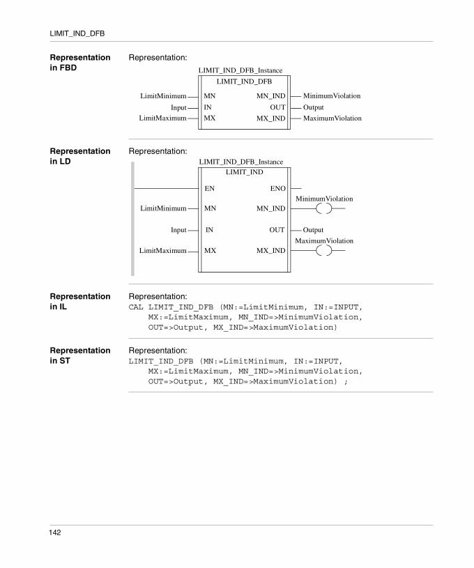
LIMIT_IND_DFB
Representation in FBD
Representation:
Representation in LD
Representation:
Representation in IL
Representation:CAL LIMIT_IND_DFB (MN:=LimitMinimum, IN:=INPUT, MX:=LimitMaximum, MN_IND=>MinimumViolation, OUT=>Output, MX_IND=>MaximumViolation)
Representation in ST
Representation:LIMIT_IND_DFB (MN:=LimitMinimum, IN:=INPUT, MX:=LimitMaximum, MN_IND=>MinimumViolation, OUT=>Output, MX_IND=>MaximumViolation) ;
MinimumViolation
LIMIT_IND_DFB
LimitMinimum
Input
LimitMaximum
Output
MaximumViolation
MN_IND
OUT
MX_IND
MN
IN
MX
LIMIT_IND_DFB_Instance
Output
LimitMaximum
ENOEN
LIMIT_IND
OUT
MN
IN
MX
LimitMinimum
Input
MinimumViolationMN_IND
MaximumViolationMX_IND
LIMIT_IND_DFB_Instance
142

LIMIT_IND_DFB
Parameter description
Description of the input parameters:
Description of the output parameters:
Parameter Data type Meaning
LimitMinim
um
BOOL, BYTE, WORD, DWORD, INT, DINT, UINT, UDINT, REAL, TIME
Limit of minimum value
Input BOOL, BYTE, WORD, DWORD, INT, DINT, UINT, UDINT, REAL, TIME
Input
LimitMaxim
um
BOOL, BYTE, WORD, DWORD, INT, DINT, UINT, UDINT, REAL, TIME
Limit of maximum value
Parameter Data type Meaning
MinimumVio
lation
BOOL Display of minimum value violation
Output BOOL, BYTE, WORD, DWORD, INT, DINT, UINT, UDINT, REAL, TIME
Output
MaximumVio
lation
BOOL Display of maximum value violation
143

LIMIT_IND_DFB
144

CBAIndex
Numerics0x Register, 23
AADD_INT, 39ANY_ARRAY_WORD, 34Application behavior change, 47
BBattery Monitoring, 22Behavior change, 47Behavior of Concept, 49Behavior of Unity, 52BOOL arrays
WORD assignment, 40BYTE_TO_BIT_DFB, 129
CChange of
application behavior, 47Concept behavior, 49Concept EFBs
CREAD_REG, 33CWRITE_REG, 33READ_REG, WRITE_REG, 33
Concept Version, 14Configuration, 15Consequences, 54Constants, 23
DFBs, 40Continuous Register Reading
CREADREG, 81Continuous Register Writing
CWRITREG, 95Conversion
Report, 35Conversion Procedure, 63Conversion Process, 61CREAD_REG, 33CREADREG, 81CWRITE_REG, 33CWRITREG, 95
145

Index
DDate, 22DDTs
Redundant names, 35Declaring EFBs, 29DFB variables
Private, 40DFBs
Constant variables, 40Initialized variables, 40
DINT_AS_WORD_DFB, 139DIOSTAT, 69DPM_time
Concept, 41Structure, 41structure, 41Unity, 41
EEF/EFB pins
type, 34EFBs, 25
replaced by function, 32values, 42
EFscorrection, 42disabled, 42executive behavior, 42outputs, 42
EQ_INT, 37, 39Execution order, 17Execution order (LD)
changed, 36Export from Concept, 64
146
Extension/CompatibilityBYTE_TO_BIT_DFB, 129CREADREG, 81CWRITREG, 95DINT_AS_WORD_DFB, 139DIOSTAT, 69GET_TOD, 125LOOKUP_TABLE1_DFB, 101PLCSTAT, 105READREG, 75RIOSTAT, 71SET_TOD, 121WORD_AS_BYTE_DFB, 137WORD_TO_BIT_DFB, 133WRITEREG, 89
FFBD Function Block Diagram, 30FBI_ST1_75_33, 32Function
EFB replaced by, 32Not present in Unity, 32
Function Block Diagram FBD, 30
GGeneral Description, 11Generic EFBs, 28GET_TOD, 44, 125Global Variables, 18
HHardware Platforms, 14Hot Standby, 16HSBY, 16

Index
IIEC demands, 50IL Instruction List, 28Import to Unity Pro, 65Incomplete LD generation, 35Indices, 40
ST, 40Initial values, 45INOUT parameters, 33Instruction List IL, 28
LLadder Diagram LD, 28Ladder Diagram LL984, 29Language differences, 31LD
Execution order changed, 36Incomplete generation, 35
LD Ladder Diagram, 28Limit with Indicator
LIMIT_IND_DFB, 141LIMIT_IND_DFB, 141LL984 Ladder Diagram, 29LL984 Restrictions, 15Located Variable, 22LOOKUP_TABLE1_DFB, 101
MMacros, 30, 46Module Function Status (DIO)
DIOSTAT, 69Module Function Status (RIO)
RIOSTAT, 71
NNames
Redundant (DDT and section), 35
OOnline modification
SFC section, 43
PParallel/Alternative Sequence, 27Parameter type
Changed, 33pins
EF/EFB, 34PLC Function Status
PLCSTAT, 105PLC Types Quantum, 14PLCSTAT, 105Possible application behavior change, 47Program Execution, 17Programming Language FBD, 30Programming Language IL, 28Programming Language LD, 28Programming Language LL984, 29Programming Language SFC, 27Programming Language ST, 28
QQuantum PLC Types, 14
RRead Register
READREG, 75READ_REG, 33Reading the Hardware Clock (Time Of Day)
GET_TOD, 125READREG, 75REAL
Calculating, 40REAL_TO_DINT, 40Redundant names
DDTs and sections, 35Reference Data Editor (RDE), 18Remote I/O Control, 24Requirements, 13RIOSTAT, 71
147
Index
SSections
Redundant names, 35Security, 17Sequential Function Chart SFC, 27SET_BIT, 32SET_BITX, 32SET_TOD, 44, 121Setting the Hardware Clock (Time Of Day)
SET_TOD, 121Setting Variables Cyclically, 24SFC Chart
Modifying, 43SFC Sequential Function Chart, 27Single Sweep Function, 17Specified execution order, 17ST code, 40ST Structured Text, 28State RAM, 19Statistics
LIMIT_IND_DFB, 141Structure
Alignment changed, 41Structured Text ST, 28System, 17System timer, 44
TThe Conversion Process, 61TIME
Calculating, 40Timer, 22Topological address
overlapping, 41Topological Addresses, 22Traverse progression with 1st degree interpolation
LOOKUP_TABLE1_DFB, 101Type Conversion
BYTE_TO_BIT_DFB, 129DINT_AS_WORD_DFB, 139WORD_AS_BYTE_DFB, 137WORD_TO_BIT_DFB, 133
148
UUnique name requirement, 35Unity behavior, 52
WWeekday numbering, 44WORD assignment
BOOL arrays, 40WORD_AS_BYTE_DFB, 137WORD_TO_BIT_DFB, 133Write Register
WRITEREG, 89WRITE_REG, 33WRITEREG, 89