Unity - Leisure Travel Vans · Unity Motorhome 1 Introduction Introduction Congratulations! Thank...
128
OWNER’S MANUAL Unity
Transcript of Unity - Leisure Travel Vans · Unity Motorhome 1 Introduction Introduction Congratulations! Thank...
OWNER’S MANUALUnity

Unity MotorhomeContents
Table of Contents
Introduction 1Owner’s Manual 1
Motorhome Information Kit 2Options and Equipment 2
Vehicle Certification Labels 3Reference Number Codes: 3Service Assistance 17Reporting Safety Defects 17Coach Specifications 17
Safety 18General Safety 18Alarms 19LP Gas Alarm 19Fuel and Propane Safety 19Combination Carbon Monoxide/Smoke Alarm 20Smoke Alarm 20Fire Prevention 21Fire Safety Tips 21Emergency Escape 21Fire Extinguisher 22
Vehicle Operations 23Vehicle Preparation 23Keys 23Vehicle Loading and Weights 23Towing 24Auxiliary Vehicle Towing 24Pre-Trip Inspection 25Emergency Equipment Checklist 26Final Checks 26Maximum Occupancy 26Seat / Shoulder Belts 27Driver / Passenger Seat Controls 28Travelling 30Driving Characteristics 30Driving Safety Tips 31Travel Tips 31Severe Weather Information 32Emergencies While Driving 33Hazard Warning Lights 33
Flat Tire 33When the Vehicle is Disabled 33Overheating 34Parking 34Extended Occupancy 35Levelling the Motorhome 35Stabilizers 36Refuelling of Vehicle Chassis 36Door Locks 38Entry Door Step 38Step Override Switch 39Exterior/Interior Light Switches 39Under Cabinet Lights 39Step Cover 40Slide Out Room 40Slide Out Room Emergency Operation 42Awning 43
Appliance and Equipment Operation 45Refrigerator 45Exterior Refrigerator Compartment 46Stove Top 46Microwave/Convection Oven 47LP Gas Furnace 48Roof Air Conditioner with Heat Pump 49Heat Pump 49Coach Power Roof Vent 50Bathroom Roof Vent 51Side Window Vents 51Manual Roof Vent 52Operating the TV 53TV Utility Panel 54External Cable TV Connection 55External Satellite TV Connection 55TV Antenna 55HDMI Switch Box 55Murphy Bed 61Corner Bed 64Seating / Sleeping 65
Electrical System Operation 66Electrical Supply 66
Unity MotorhomeContents
System Monitor 73Power Distribution Panel 74120 Volt AC Circuit Breakers 7412 Volt DC Coach Fuses 7512 Volt DC Chassis Fuses 75Ground Fault Circuit Interrupter (GFCI) 75Auxiliary LP Gas Generator (Optional) 76Auxiliary Diesel Generator (Optional) 77Generator Safety 78Automatic Power Transfer Switch 7812 Volt DC system 79Chassis Battery 79Coach Batteries 12 Volt DC 80Coach Battery Condition Meter 80Battery Maintenance 80Inverter 82Inverter Remote Control Panel 83Surge Guard® RV Power Protection 84Lighting Maintenance 85Water / Plumbing System 89Fresh Water System 89External Water Supply 89Filling the Tank with Fresh Water 90Water Pump Switch 91Water Pump 92Fresh Water Tank and Water System Drain 92Water Pump Initial Startup 93Water Pump Troubleshooting 93Water Filter 94Disinfection of Water Tank 94Waste Systems 95Grey Water - Waste Holding Tank 95Black Water - Waste Holding Tank 95Dumping Holding Tanks 95Black Water Waste Tank Rinse 96Macerator 97Do’s and Don‘ts - Holding Tanks 97Using On-Site Sewer Hook-Ups 97Water Heater 98Water Heater Thermal Cut-Off Valve 99Water Heater Bypass Valve 99
Water Heater (Optional On-Demand) 100Water Heater Bypass Valve 100Water Fixtures 101Fresh Water Toilet 101
Liquid Propane Gas System 104LP Valve Gas Control (Utility Center) 104Safe Use Of LP Gas 104Selecting Fuel Types 105How LP Gas Works 105LP Gas Tank System 105Refilling LP Gas Tank 105Air in the LP Gas Tank 106Travelling with LP Gas 106LP Gas Tank Regulator 106LP Gas Leaks 106Avoiding Asphyxiation 108
Motorhome Maintenance 109Exterior Care and Maintenance 109Interior Care 110
Storage and Winterization 113Storage Checklist 113Cold Temperature Storage 114Water & Waste System Winterization 115De-Winterizing the Water Systems 116Spring Startup 116Cold Temperature Operation 116Chassis 116LP Gas 116Waste System 116Maintenance and Service 117
NEW VEHICLE LIMITED WARRANTY 119

Unity Motorhome
1
Introduction
IntroductionCongratulations! Thank you for selecting a Leisure Travel Vans Motorhome.
Welcome to the exciting world of motorhome travel and camping, with all the comforts of home with you, while you travel and enjoy the outdoors.
Your motorhome has been designed and manufactured to enhance your travel and camping experience, and to provide you with sa e, e ficient and trou le ree operation
e ore your first drive, eco e a iliar with the operation of the vehicle chassis and all functions and operations of the motorhome. Spend adequate time with your dealer when you take delivery to learn all you can about your new motorhome.
Owner’s ManualThis manual was prepared to aid the operator in the operation and care of the motorhome. There are many options to Leisure Travel Vans, so ensure that you are familiar with your motorhome’s systems and equipment. All operators and occupants of the motorhome should read, understand and follow the instructions in this manual, the vehicle chassis manual & the information contained in the Motorhome Information Kit provided with your new motorhome.
Your motorhome contains a number of systems, components, equipment and appliances manufactured by vendors that supply components for Leisure Travel Vans. These vendors are unrelated to Triple E Canada Ltd.
e ore operating the otorho e or the first time – even if an experienced motorhome operator – read and become familiar with all of the relevant manuals to your motorhome, components, equipment and appliances provided in the Motorhome Information Kit. Your familiarity with the detailed operation of your
otorho e will assist in your sa e, e ficient and trouble free motorhome operation.
KEEP the Motorhome Information Kit within your motorhome for readily available reference.
PASS this Operator’s Manual, the Chassis Operation Manual and the Motorhome Information Kit to any subsequent operator or owner.
or clarification or urther details on any o the enclosed information, please contact:
Your Leisure Travel Vans Dealer or Triple E RV Customer Service at:
Email: [email protected] Toll ree 877 992 990 Telephone 20 325 3 1
a 20 325 52 1

Unity Motorhome
2
Motorhome Information KitThe information kit includes but isn’t limited to information on the following components, equipment and appliances listed below.
Introduction
RefrigeratorStove topFurnaceElectrical PanelToiletWater HeaterWater PumpWater FiltrationVent (roof)Fire ExtinguisherSmoke DetectorThermostatCO DetectorPropane DetectorGas RegulatorTV AntennaTV/DVDChassisAir ConditionerGeneratorStabilizersRearview MonitorInverterEntertainment SystemSafetyFlooring and CountertopsElectric StepSolar PanelSurge ProtectorSafe
Options and EquipmentTriple E Recreational Vehicles are available in various si es and oor plan configurations and differing optional equipment. The equipment, accessories and components described in this manual may not apply in all respects to your motorhome. Read the material and manuals provided in the motorhome Information Kit for detailed instructions regarding the equipment specific to your otorho e
Unity Motorhome
3
Introduction
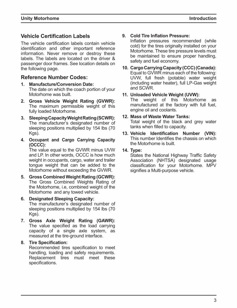
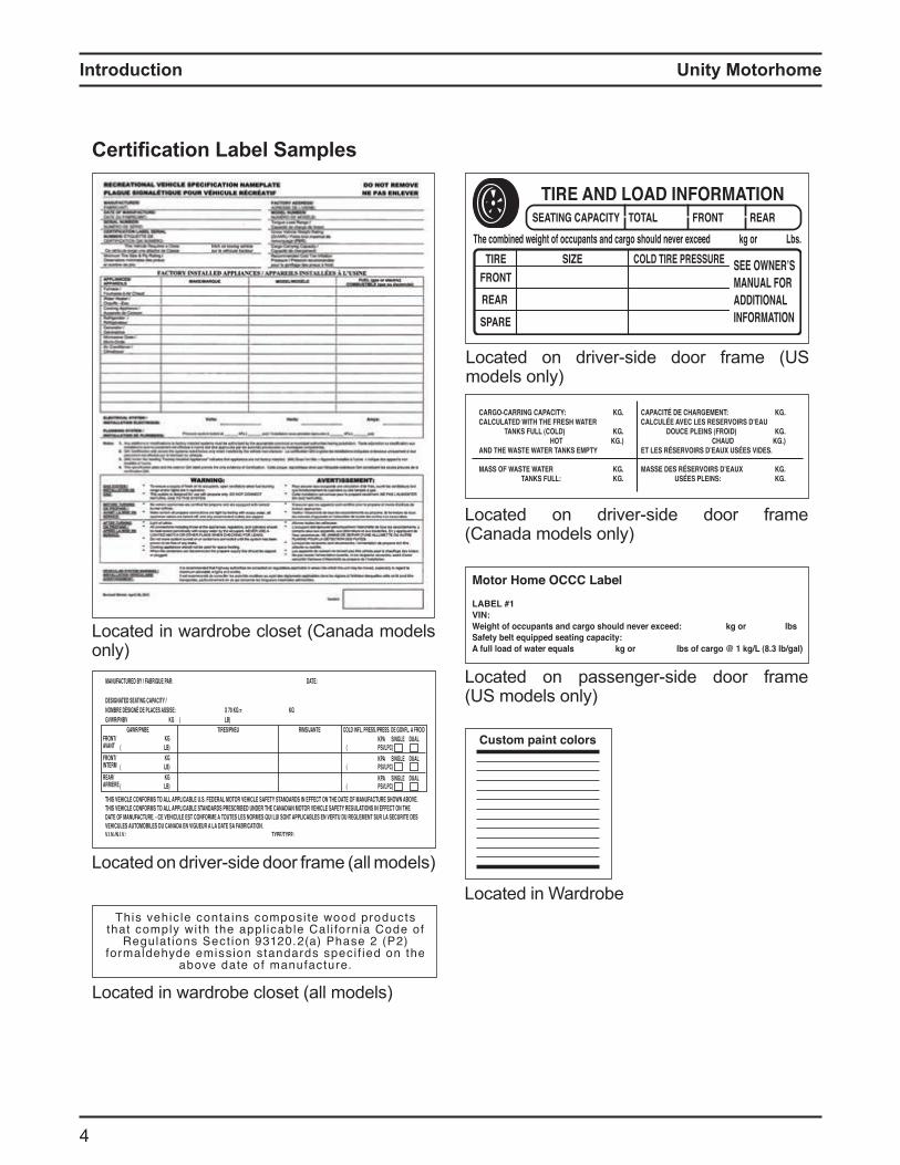
Vehicle Certification LabelsThe vehicle certification la els contain vehicle identification and other i portant re erence information. Never remove or destroy these labels. The labels are located on the driver & passenger door frames. See location details on the following page.
eference umber Codes1. anufacture Conversion ate
The date on which the coach portion of your Motorhome was built.
2. ross Vehicle Weight ating VWThe maximum permissible weight of this fully loaded Motorhome.
3. Sleeping Capacit Weight ating SCWThe manufacturer’s designated number of sleeping positions ultiplied y 15 l s 70 Kgs).
4. Occupant and Cargo Carrying Capacity OCCC
The value equal to the GVWR minus UVW and LP. In other words, OCCC is how much weight in occupants, cargo, water and trailer tongue weight that can be added to the Motorhome without exceeding the GVWR.
5. ross Combined Weight ating CW The Gross Combined Weights Rating of the Motorhome, i.e, combined weight of the Motorhome and any towed vehicle.
6. esignated Sleeping Capacit The manufacturer’s designated number of sleeping positions ultiplied y 15 l s 70 Kgs).
7. ross le Weight ating WThe value specified as the load carrying capacity of a single axle system, as
easured at the tire ground inter ace8. ire Specification
Reco ended tires specification to eet handling, loading and safety requirements. Replacement tires must meet these specifications
9. Cold ire n ation ressure n ation pressures reco ended while cold) for the tires originally installed on your Motorhome. These tire pressure levels must be maintained to ensure proper handling, safety and fuel economy.
10. Cargo Carr ing Capacit CCC CanadaEqual to GVWR minus each of the following: UVW, full fresh (potable) water weight including water heater , ull LP Gas weight
and SCWR.11. nloaded Vehicle Weight VW
The weight of this Motorhome as manufactured at the factory with full fuel, engine oil and coolants.
12. ass of Waste Water an s Total weight of the black and grey water tanks when filled to capacity
13. Vehicle dentification umber VThis nu er dentifies the chassis on which the Motorhome is built.
14. pe States the ational ighway Tra fic Sa ety Association (NHTSA) designated usage classification or your otorho e P signifies a ulti purpose vehicle
Unity MotorhomeIntroduction
Certification Label Samples
Located in Wardrobe
Located in wardrobe closet (Canada models only)
Located in wardrobe closet (all models)
Located on driver side door ra e all odels
Located on driver side door ra e S models only)
Located on passenger side door ra e (US models only)
Located on driver side door ra e (Canada models only)
Unity Motorhome
5
Introduction
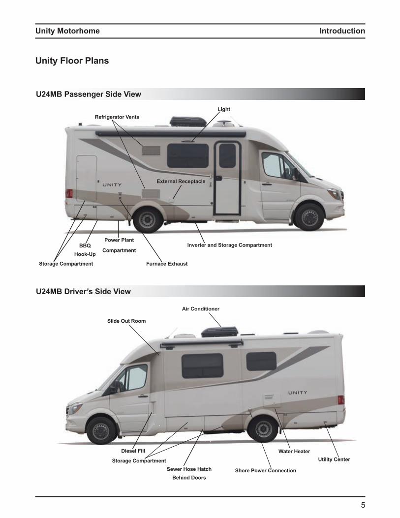
nit loor lans
2 assenger Side View
Air Conditioner
Slide Out Room
Diesel Fill
Shore ower Connection
Utility Center
Furnace Exhaust
External Receptacle
Storage Compartment
Refrigerator VentsLight
ower lant
CompartmentInverter and Storage Compartment
Sewer Hose HatchBehind Doors
Water Heater
BBQHook-Up
U24MB Driver’s Side View
Storage Compartment
Unity MotorhomeIntroduction
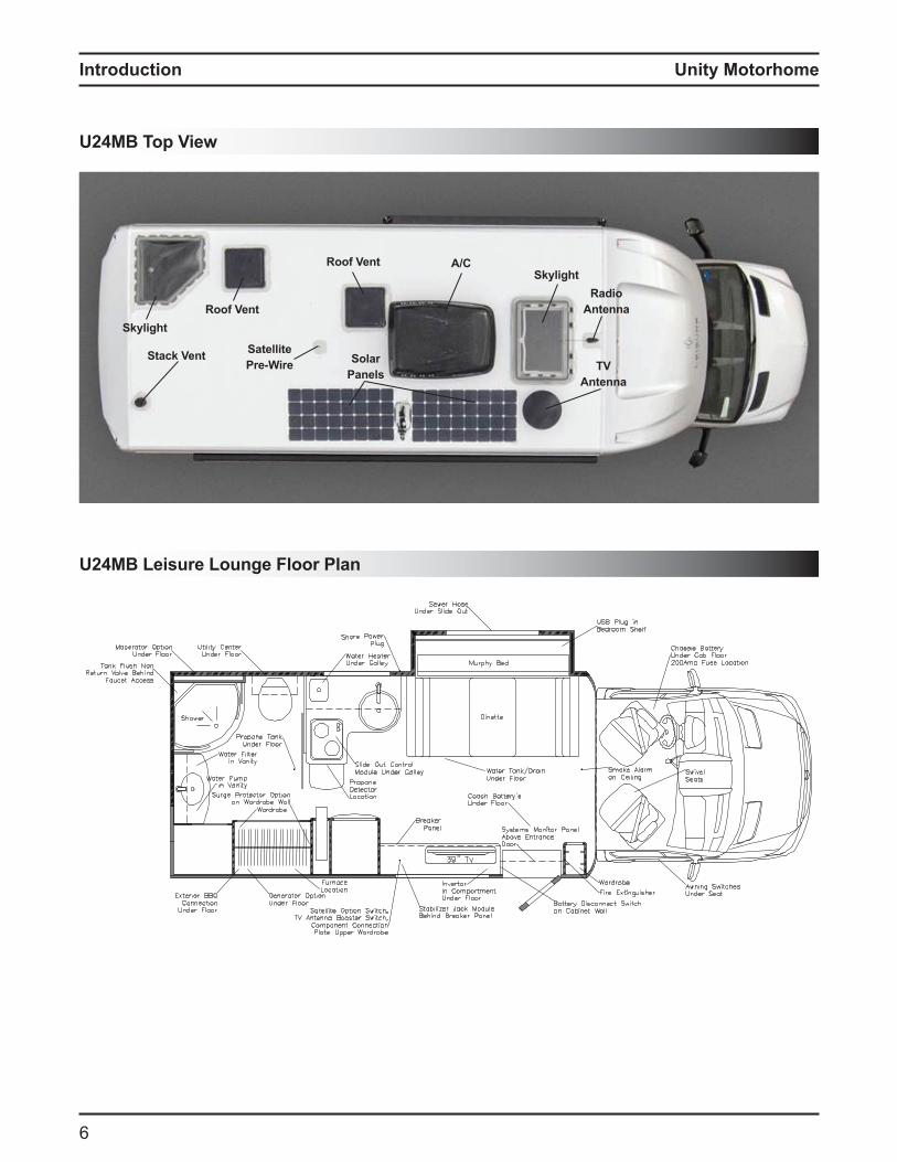
U24MB Top View
2 Leisure Lounge loor lan
Skylight Radio
Antenna
TVAntenna
Stack Vent Satellitere Wire Solar
anels
A/CRoof Vent
Roof VentSkylight
Unity Motorhome
7
Introduction
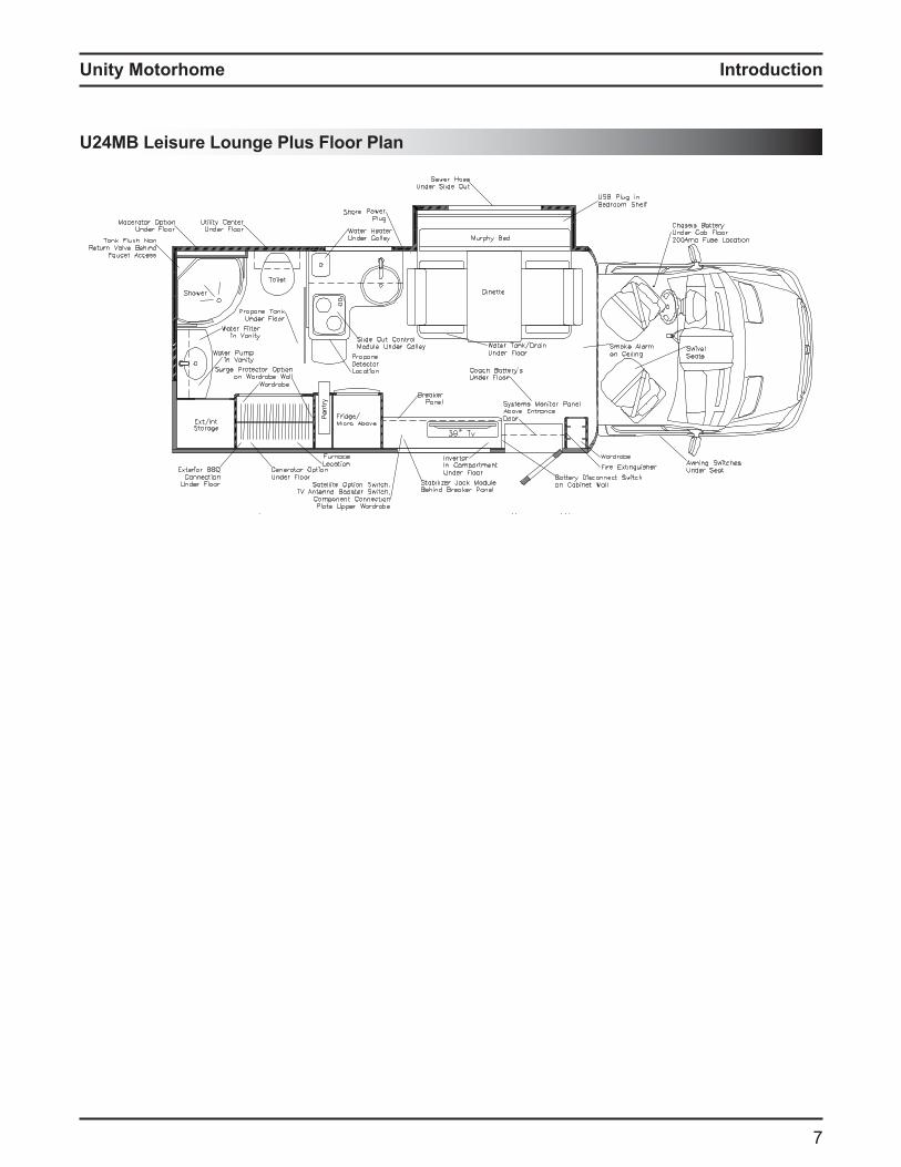
2 Leisure Lounge lus loor lan

Unity Motorhome
8
Introduction
U24CB Driver’s Side View
2 C assenger Side View
Air Conditioner
Slide Out Room
Shore ower Connection
Water Heater
Storage Compartment
Utility Center
Refrigerator Vents
Furnace Exhaust
Storage Compartment
BBQHook-Up
Sewer Hose HatchBehind Doors
Diesel Fill
ower lantCompartment
StorageCompartment
Light
Inverter and StorageCompartmentExternal Receptacle
Unity Motorhome
9
Introduction
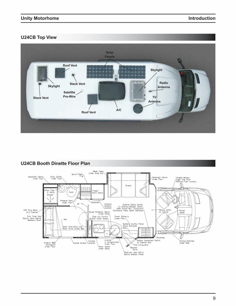
2 C ooth inette loor lan
U24CB Top View
Skylight
RadioAntenna
TVAntenna
Stack Vent
Satellitere Wire
Solaranels
A/CRoof Vent
Roof Vent
Skylight
Stack Vent

Unity Motorhome
10
Introduction
2 C Lounge loor lan

Unity Motorhome
11
Introduction
U24IB Driver’s Side View
2 assenger Side View
Air Conditioner
Shore ower Connection
Utility Center
Refrigerator Vents
Furnace Exhaust
Storage CompartmentStorage Compartment
Light
Inverter and Storage Compartmentower lant
Compartment
StorageCompartment
Diesel Fill
Water Heater
Sewer Hose HatchBehind Doors
External Receptacle
BBQHook-Up
Storage Compartment
Unity Motorhome
12
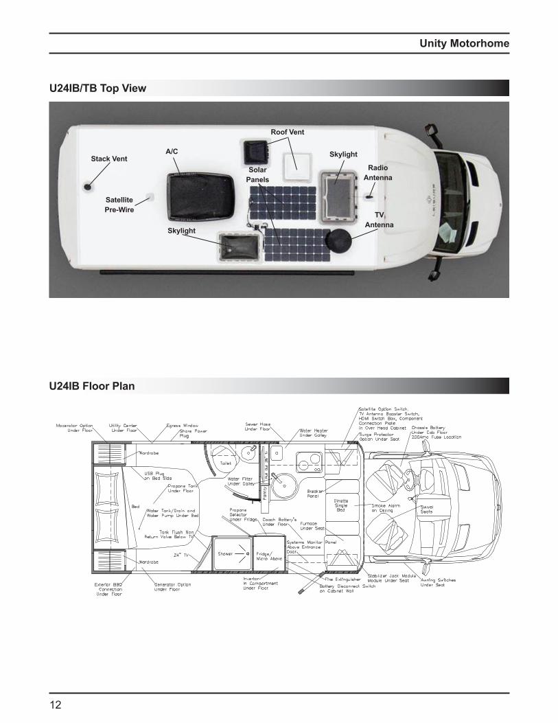
2 loor lan
U24IB/TB Top View
Skylight
RadioAntenna
TVAntenna
Stack Vent
Satellitere Wire
Solaranels
A/C
Roof Vent
Skylight
Unity Motorhome
13
Introduction
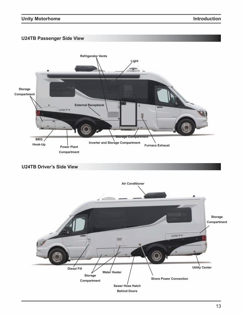
Air Conditioner
Diesel Fill
Shore ower Connection
Water HeaterUtility Center
Refrigerator Vents
StorageCompartment
Light
StorageCompartment
Sewer Hose HatchBehind Doors
Furnace ExhaustInverter and Storage Compartment
Storage CompartmentBBQ
Hook-Upower lant
Compartment
U24TB Driver’s Side View
2 assenger Side View
External Receptacle
StorageCompartment
Unity Motorhome
1
Introduction
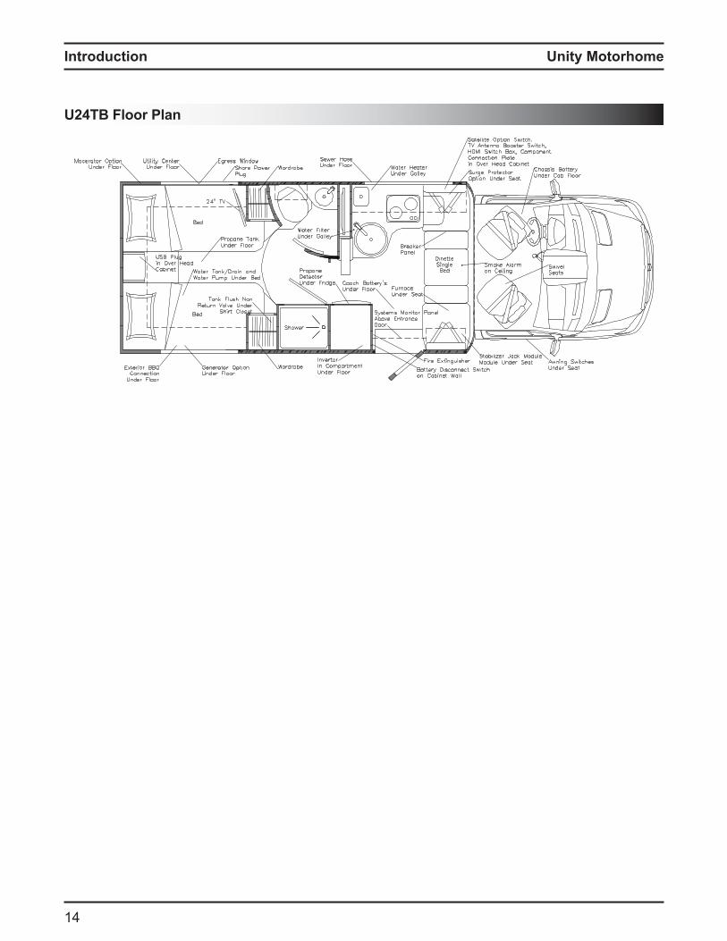
2 loor lan
Unity Motorhome
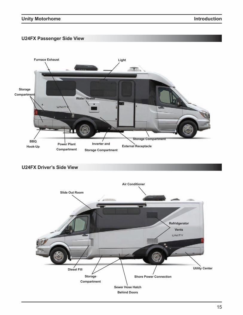
15
Introduction
Air Conditioner
Diesel Fill
Shore ower Connection
Utility Center
StorageCompartment
Light
Refridgerator
Vents
Sewer Hose HatchBehind Doors
Furnace Exhaust
Inverter and
Storage Compartment
Storage CompartmentBBQ
Hook-Upower lant
Compartment
U24FX Driver’s Side View
2 assenger Side View
Water Heater
StorageCompartment
External Receptacle
Slide Out Room
Unity Motorhome
1
Introduction
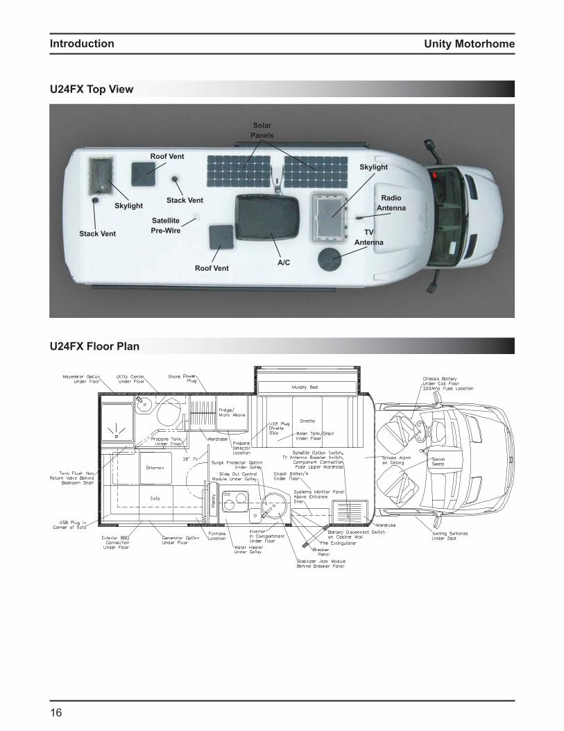
2 loor lan
U24FX Top View
Skylight
RadioAntenna
TVAntenna
Stack Vent
Satellitere Wire
Solaranels
A/CRoof Vent
Roof Vent
Skylight
Stack Vent
Unity Motorhome
17
Introduction
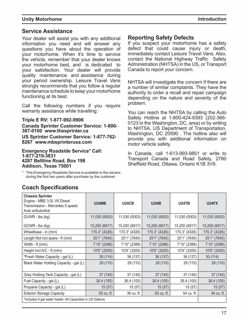
Service Assistance
Your dealer will assist you with any additional information you need and will answer any questions you have about the operation of your motorhome. When it’s time to service the vehicle, remember that your dealer knows your motorhome best, and is dedicated to your satisfaction. Your dealer will provide quality maintenance and assistance during your period ownership. Leisure Travel Vans strongly recommends that you follow a regular maintenance schedule to keep your motorhome functioning at its best.
Call the following numbers if you require warranty assistance while travelling:
Triple E RV: 1-877-992-9906
Canada Sprinter Customer Service: 1-800-
387-0100 www.thesprinter.ca
US Sprinter Customer Service: 1-877-762-
8267 www.mbsprinterusa.com
Emergency Roadside Service* Call:
1-877-219-3831
4287 Beltline Road, Box 198
Addison, Texas 75001
Coach SpecificationsChassis Sprinter
Engine - MBE 3.0L V6 Diesel Transmission - Mercedes 5 speed Auto w/Autostick
U24MB U24CB U24IB U24TB U24FX
GVWR - lbs (kg)
GCWR - lbs (kg)
11,030 (5003)
15,250 (6917)
11,030 (5003)
15,250 (6917)
11,030 (5003)
15,250 (6917)
11,030 (5003)
15,250 (6917)
11,030 (5003)
15,250 (6917)Wheelbase - in (mm) 170.3” (4326) 170.3” (4326) 170.3” (4326) 170.3” (4326) 170.3” (4326)Length Not incl spare - ft (mm) 25’1” (7645) 25’1” (7645) 25’1” (7645) 25’1” (7645) 25’1” (7645)Width - ft (mm) 7’10” (2388) 7’10” (2388) 7’10” (2388) 7’10” (2388) 7’10” (2388)Height Incl A/C - ft (mm) 10’6” (3200) 10’6” (3200) 10’6” (3200) 10’6” (3200) 10’6” (3200)*Fresh Water Capacity - gal (L) 30 (114) 36 (137) 36 (137) 36 (137) 30 (114)Black Water Holding Capacity - gal (L) 29 (110) 29 (110) 29 (110) 29 (110) 29 (110)
Grey Holding Tank Capacity - gal (L) 37 (140) 37 (140) 37 (140) 37 (140) 37 (140)Fuel Capacity - gal (L) 26.4 (100) 26.4 (100) 26.4 (100) 26.4 (100) 26.4 (100)Propane Capacity - gal (L) 15 (57) 15 (57) 15 (57) 15 (57) 15 (57)Exterior Storage Capacity 55 cu. ft. 36 cu. ft. 63 cu. ft. 54 cu. ft. 34 cu. ft.*Includes 6 gal water heater. All Capacities in US Gallons
* This Emergency Roadside Service is available to the owners during the first two years a ter purchase y the custo er
Reporting Safety Defects
If you suspect your motorhome has a safety defect that could cause injury or death, immediately contact Leisure Travel Vans. Also, contact the ational ighway Tra fic Sa ety Administration (NHTSA) in the US, or Transport Canada to report your concern.
NHTSA will investigate the concern if there are a number of similar complaints. They have the authority to order a recall and repair campaign depending on the nature and severity of the problem.
You can reach the NHTSA by calling the Auto Safety Hotline at 1-800-424-9393 (202-366-0123 in the Washington, DC, area) or by writing to NHTSA, US Department of Transportation, Washington, DC 20590 . The hotline also will provide you with additional information on motor vehicle safety.
In Canada, call 1-613-993-9851 or write to Transport Canada and Road Safety, 2780 She field Road, ttawa, ntario 1 3 9
Unity Motorhome
18
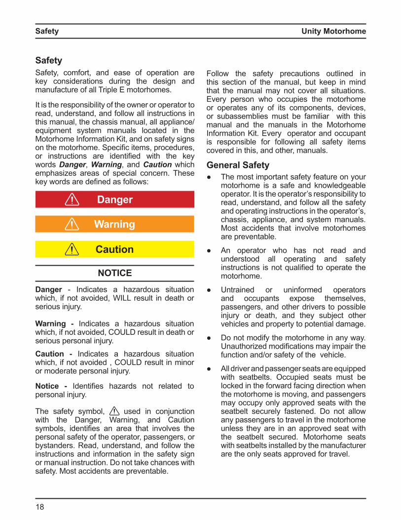
Caution
Warning
Danger ndicates a ha ardous situation which, if not avoided, WILL result in death or serious injury.
Warning - Indicates a hazardous situation which, if not avoided, COULD result in death or serious personal injury.Caution - Indicates a hazardous situation which, if not avoided , COULD result in minor or moderate personal injury.
Notice - dentifies ha ards not related to personal injury.
Danger
NOTICE
SafetySafety, comfort, and ease of operation are key considerations during the design and manufacture of all Triple E motorhomes.
It is the responsibility of the owner or operator to read, understand, and follow all instructions in this manual, the chassis manual, all appliance/equipment system manuals located in the Motorhome Information Kit, and on safety signs on the otorho e Specific ite s, procedures, or instructions are identified with the key words Danger, Warning, and Caution which emphasizes areas of special concern. These key words are defined as ollows
The safety symbol, used in conjunction with the Danger, Warning, and Caution sy ols, identifies an area that involves the personal safety of the operator, passengers, or bystanders. Read, understand, and follow the instructions and information in the safety sign or manual instruction. Do not take chances with safety. Most accidents are preventable.
Follow the safety precautions outlined in this section of the manual, but keep in mind that the manual may not cover all situations. Every person who occupies the motorhome or operates any of its components, devices, or subassemblies must be familiar with this manual and the manuals in the Motorhome Information Kit. Every operator and occupant is responsible for following all safety items covered in this, and other, manuals.
General Safety The most important safety feature on your
motorhome is a safe and knowledgeable operator. It is the operator’s responsibility to read, understand, and follow all the safety and operating instructions in the operator’s, chassis, appliance, and system manuals. Most accidents that involve motorhomes are preventable.
An operator who has not read and understood all operating and safety instructions is not ualified to operate the motorhome.
Untrained or uninformed operators and occupants expose themselves, passengers, and other drivers to possible injury or death, and they subject other vehicles and property to potential damage.
Do not modify the motorhome in any way. nauthori ed odifications ay i pair the
function and/or safety of the vehicle.
All driver and passenger seats are equipped with seatbelts. Occupied seats must be locked in the forward facing direction when the motorhome is moving, and passengers may occupy only approved seats with the seatbelt securely fastened. Do not allow any passengers to travel in the motorhome unless they are in an approved seat with the seatbelt secured. Motorhome seats with seatbelts installed by the manufacturer are the only seats approved for travel.
Safety
Unity Motorhome
19
Safety
3 Re er to Li uid Propane Gas Syste section in this manual and LP Gas Alarm owner’s manual located in the Motorhome Information Kit for further details.
If you smell gas, immediately follow these steps
tinguish open a es, pilot lights, and all smoking materials.
5 Do not touch any electrical switches. Shut off the LP gas tank valve.
7. Open doors, windows, and roof vents after aking sure the roo vent ans are
8. Leave the area until odor is gone.9 ave a ualified service technician check the
system for leaks and make any necessary corrections and repairs..
O o O remove the label from the glass stove top cover.
uel and ropane Safet
Turn off all pilot lights, appliances, and appliance igniters before refueling motorhome diesel or propane tanks. Failure to comply could result in death or serious injury.
Always fasten the seatbelt low on the torso and keep it snug to transmit the force from the belt into the hip/pelvic region of the body. Pregnant women should wear a lap/shoulder belt whenever possible. Wear the belt snug and low throughout the pregnancy.
sta lish a onthly fire e tinguisher inspection program to ensure the extinguisher is fully charged and in proper working condition. Inspect the extinguisher prior to operating or occupying the motorhome.
AlarmsAll models are equipped with a combination LP gas, carbon monoxide, and smoke alarm as standard safety equipment.
Recurring alarms indicate the slow accumulation of L gas carbon mono ide or smo e and warn of low batter levels. Have an authorized service center check the system and identify the source of the alarm. Correct the problem before using the motorhome. Keep all alarms in good working order. For detailed information, refer to the alarm manuals provided in the Motorhome Information Kit.
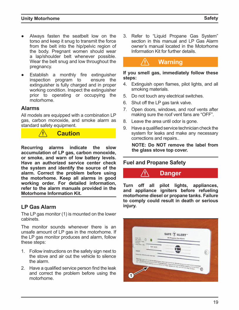
L as larmThe LP gas monitor (1) is mounted on the lower cabinets.The monitor sounds whenever there is an unsafe amount of LP gas in the motorhome. If the LP gas monitor produces and alarm, follow these steps:
1. Follow instructions on the safety sign next to the stove and air out the vehicle to silence the alarm.
2 ave a ualified service person find the leak and correct the problem before using the motorhome. 1
Caution
Warning
Danger
Unity Motorhome
20
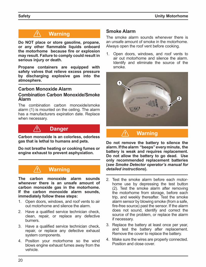
Smoke AlarmThe smoke alarm sounds whenever there is an unsafe amount of smoke in the motorhome. Always open the roof vent before cooking.
1. Open doors, windows, and roof vents to air out motorhome and silence the alarm. Identify and eliminate the source of the smoke.
o not remove the batter to silence the alarm. f the alarm beeps ever minute the batter is wea and re uires replacement.
o not allow the batter to go dead. se onl recommended replacement batteries (see Smoke Detector operator’s manual for detailed instructions).
2 Test the s oke alar e ore each otorhome use by depressing the test button 2 Test the s oke alar a ter re oving
the motorhome from storage, before each trip, and weekly thereafter. Test the smoke alarm sensor by blowing smoke (from a safe, fire ree source past the sensor the alar does not sound, identify and correct the source of the problem, or replace the alarm if necessary.
3 Replace the battery at least once per year, and test the battery after replacement. Remove the cover to replace the battery.
Make sure the wires are properly connected. Position and close cover.
Do NOT place or store gasoline, propane, or an other ammable li uids onboard the motorhome because fire or e plosion may result. Failure to comply could result in serious injury or death.
ropane containers are e uipped with safety valves that relieve excess pressure b discharging e plosive gas into the atmosphere.
Carbon ono ide larm Combination Carbon ono ide Smo e AlarmThe combination carbon monoxide/smoke alarm (1) is mounted on the ceiling. The alarm has a manufacturers expiration date. Replace when necessary.
Carbon mono ide is an colorless odorless gas that is lethal to humans and pets.
o not breathe heating or coo ing fumes or engine exhaust to prevent asphyxiation.
he carbon mono ide alarm sounds whenever there is an unsafe amount of carbon mono ide gas in the motorhome. f the carbon mono ide alarm sounds immediatel follow these steps1. Open doors, windows, and roof vents to air
out motorhome and silence the alarm.2 ave a ualified service technician check,
clean, repair, or replace any defective burners.
3 ave a ualified service technician check, repair, or replace any defective exhaust system components.
Position your motorhome so the wind blows engine exhaust fumes away from the vehicle.
1
2
Warning
WarningDanger
Warning
Safety
Unity Motorhome
21
Safety
5 Clean and vacuum opening on smoke alarm once a month.
If you suspect the smoke alarm is not functioning properly, replace the alarm—do NOT attempt to repair it.
NOTICESmoke alarms are not perfect and do not respond in all situations. he best safeguard is fire prevention.
ire reventionFires can start in a variety of ways including, but not limited to, smoking, malfunctioning appliances or e uip ent, placing a a le materials on hot surfaces, etc. It is better to prevent fires, ut e prepared to e tinguish a fire i necessary Review the ollowing sections with all operators and occupants on a regular basis:
Fire Safety Tips1. Establish and maintain good housekeeping
practices. Never allow combustible materials to accumulate.
2 Store a a le li uids in approved containers in a well ventilated space
3 ave ully charged fire e tinguishers readily available.
void using a a le products in the motorhome.
5 Never smoke in bed or when relaxing on the couch.
Do not overload electrical outlets.7. Do not leave cooking food unattended.8. Keep children away from electrical outlets
and LP gas controls.
Dangerever use a na ed ame to chec for L
gas leaks.
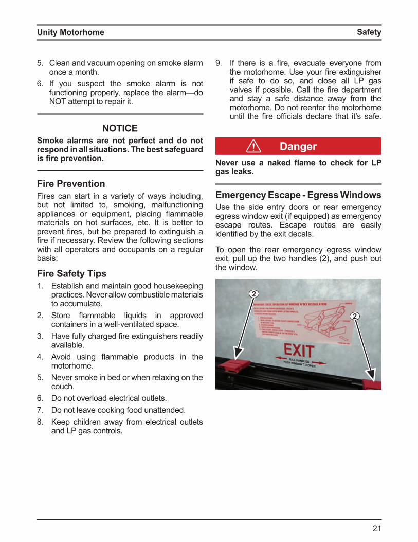
Emergency Escape - Egress WindowsUse the side entry doors or rear emergency egress window exit (if equipped) as emergency escape routes. Escape routes are easily identified y the e it decals
To open the rear emergency egress window e it, pull up the two handles 2 , and push out the window.
2
2
9 there is a fire, evacuate everyone ro the otorho e se your fire e tinguisher if safe to do so, and close all LP gas valves i possi le Call the fire depart ent and stay a safe distance away from the motorhome. Do not reenter the motorhome until the fire o ficials declare that it s sa e
Unity Motorhome
22
fter the fire is out beware of ashbac . lashbac occurs when ammable vapors
from combustible li uids spread bac to the ignition source and reignite the fire.
Functionire e tinguishers are designed to put out a fire
in its initial stages nce a fire is out o control and you cannot get within 10 eet 3 , it is too ig to fight with your e tinguisher
o not discharge your fire e tinguisher to test it Once it is discharged, even for a few seconds, it will lose pressure and become useless.
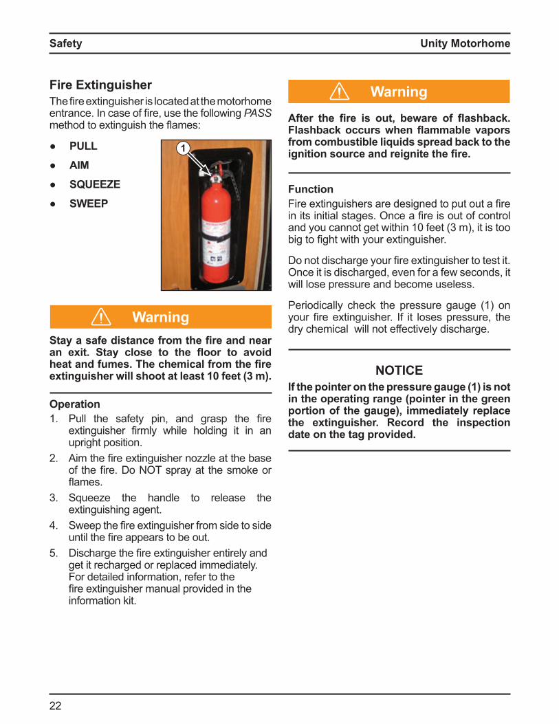
Periodically check the pressure gauge (1) on your fire e tinguisher it loses pressure, the dry chemical will not effectively discharge.
NOTICEIf the pointer on the pressure gauge (1) is not in the operating range (pointer in the green portion of the gauge), immediately replace the extinguisher. Record the inspection date on the tag provided.
WarningFire ExtinguisherThe fire e tinguisher is located at the otorho e entrance n case o fire, use the ollowing PASS
ethod to e tinguish the a es
LL
AIM
SQUEEZE
SW
Sta a safe distance from the fire and near an e it. Sta close to the oor to avoid heat and fumes. he chemical from the fire extinguisher will shoot at least 10 feet (3 m).
Operation1. Pull the sa ety pin, and grasp the fire
e tinguisher fir ly while holding it in an upright position.
2 i the fire e tinguisher no le at the ase o the fire o T spray at the s oke or a es
3 Squeeze the handle to release the extinguishing agent.
Sweep the fire e tinguisher ro side to side until the fire appears to e out
5 ischarge the fire e tinguisher entirely and get it recharged or replaced immediately. For detailed information, refer to the fire e tinguisher anual provided in the information kit.
1
Warning
Safety
Unity Motorhome
23
Vehicle Operation
Vehicle OperationVehicle reparationBefore beginning an extended trip, ensure you are thoroughly familiar with your motorhome’s components, features, appliances, and limitations. Take ample time to read the operator’s manual and the material in the Motor Information Kit, and ensure you understand the operation of all the components.
Adequate preparation is essential for an enjoyable and successful trip. Your motorhome provides the freedom to do what you want, where you want, and when you want. The time you spend getting to know your motorhome will enhance your enjoyment, maximize your experience, and contribute to a more successful trip.
KeysKeep a record of all key code numbers and keep them in a safe place—do NOT keep them in your motorhome. Key codes for the chassis can be obtained only through your local authorized Sprinter dealer.
Vehicle Loading and WeightsThe components of your vehicle are designed to perform if the motorhome is not loaded in excess of the Gross Vehicle Weight Rating (GVWR), the maximum front and rear Gross Axle Weight Rating (GAWR), or the Gross Combined Weight Rating (GCWR). These ratings are listed on the Canada and U.S. Department of Transport decals located on the driver’s seat pedestal behind the skirting.
The GVWR is the maximum permissible weight of the fully loaded motorhome.
The Unloaded Vehicle Weight (UVW) is the weight of your motorhome as manufactured at the factory with full fuel, engine oil, and coolants.
The Cargo Carrying Capacity (CCC) (Canada) is equal to the GVWR minus each of the following: UVW, full fresh (potable) water weight (including water heater), full LP gas weight, and Sleeping Capacity Weight Rating (SCWR).
The Occupant and Cargo Carrying Capacity (OCCC) is equal to the GVWR, minus UVW, plus full LP gas weight. In other words, OCCC is the amount of weight in occupants, cargo, water, and trailer tongue weight that can be added to the motorhome without exceeding the GVWR.
The Gross Combination Weight Rating (GCWR) is the maximum allowable loaded weight of the motorhome and any towed vehicle.
The Gross Axle Weight Rating (GAWR) is the value specified as the load carrying capacity o a single a le syste , as easured at the tireground interface.
To check that your motorhome is properly loaded, drive the fully loaded vehicle to a scale and weigh as follows:
1. Drive only the front wheels onto the scale to obtain the front gross axle weight.
2 Next, place the entire vehicle (both axles) onto the scale to obtain the gross vehicle weight.
3 Drive forward until only the rear wheels are on the scale, and obtain the rear gross axle weight.
To obtain the corner weight for your motorhome, drive each tire individually onto the scale and record the weight.
Compare the gross vehicle weight with the GVWR on the sticker. If the gross vehicle weight exceeds the GVWR, you will have to reduce the total vehicle load. If the gross vehicle weight is less than the GVWR on the sticker, check the front and rear gross axle weights against the front and rear GAWRs on the sticker. If either axle weight exceeds the GAWR for that axle, redistribute the load to ensure that loads on front and rear axles are within the required limits.
Load heavier items as centrally and as low as possible. Store lighter items in cabinets, closets, and drawers. Secure luggage or similar cargo inside your motorhome to prevent it from causing damage or injury.
Unity Motorhome
2
Total vehicle load must NOT exceed the maximum GVWR/GAWR/GCWR of the chassis.
TowingTowing a trailer can affect the handling, durability, performance, and fuel economy of your otorho e The actory installed class towing hitch is rated as follows:
A. 500 l 227 kg a i u hitch or tongue weight
B. 5000 l 2270 kg a i u trailer weight
The combined weight of the motorhome and any towed vehicle must not exceed the Gross Combined Weight Rating (GCWR). Also, the combined weight of the motorhome and any towed vehicle hitch weight must not exceed the motorhome’s Gross Vehicle Weight Rating (GVWR) or its rear Gross Axle Weight Rating G WR as listed on the vehicle certification
label.
GCWR 15,250 l 917 kg
To ensure the correct weight balance, take your loaded motorhome to a weigh scale to determine the actual weight distribution. After you have done this once, you will have a better understanding about how to load your vehicle in the future.
Remember, your motorhome will handle differently when towing a trailer, and stopping distances will be longer. Make sure your trailer is equipped with a braking system and is properly connected to your motorhome.
When descending a steep or long grade, reduce speed and shift to a lower gear to control speed. Avoid prolonged or frequent application of brakes to prevent overheating and possible brake system failure. Refer to the chassis manual in the Motorhome Information Kit for further information.
Caution Auxiliary Vehicle TowingIf you are planning to tow another vehicle or a trailer with your motorhome, contact your local
T or towing in or ation Re er to section 12 for more details.
For safe towing and vehicle handling, maintain proper motorhome and trailer weight distribution. he total weight of the motorhome and the towed vehicle must not exceed the GCVW rating as stated on the vehicle certification label.
It is the responsibility of the operator to be sure the otorho e loading specifications are not exceeded. Always weigh and reload if required. Keep all frame members level or the tow hitch angled slightly upward for the best results. Be familiar with and comply with all DOT regulations.
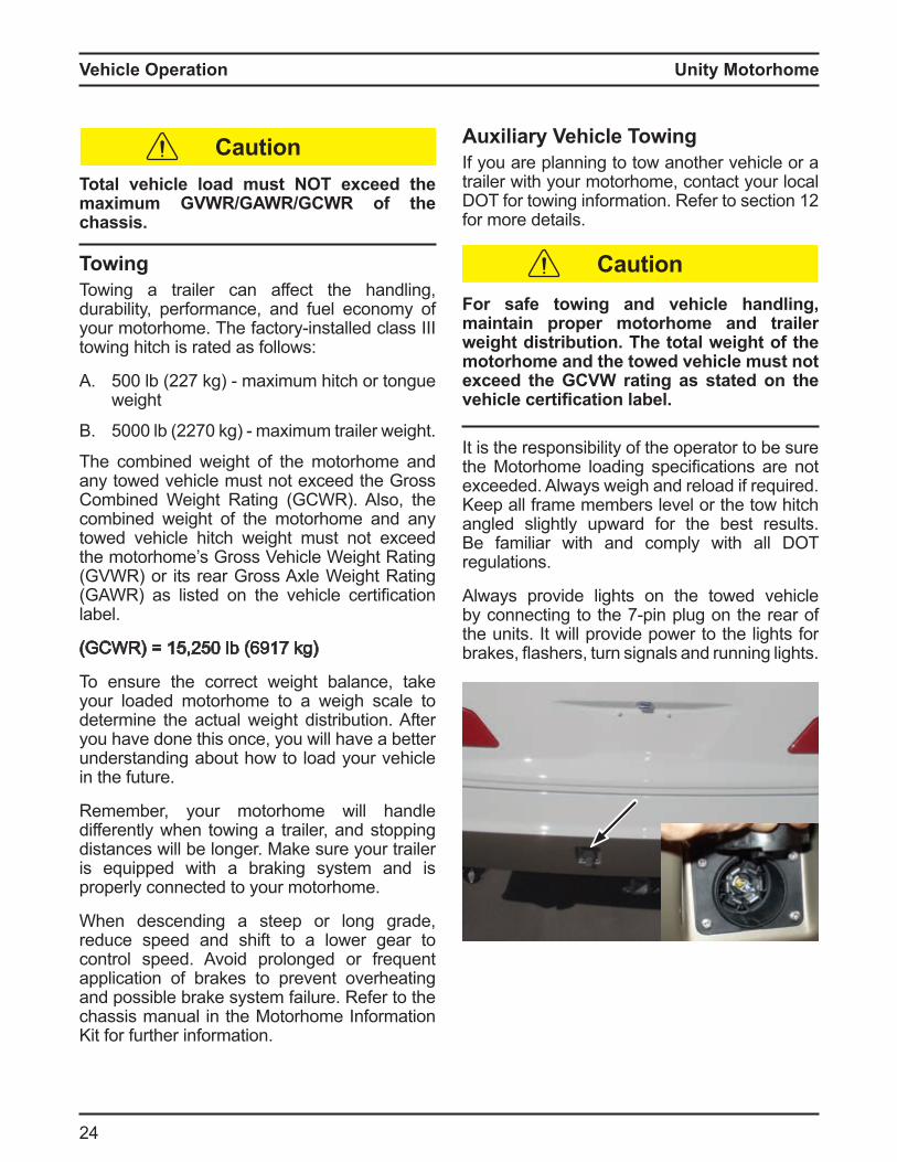
Always provide lights on the towed vehicle y connecting to the 7 pin plug on the rear o
the units. It will provide power to the lights for rakes, ashers, turn signals and running lights
Caution
Vehicle Operation
Unity Motorhome
25
Vehicle Operation
10 ill the LP gas tank to a a i u o 80 o its capacity e care ul not to overfill the LP gas tank n overfilled LP gas tank will cause the gas regulator to fail, and may result in problems with LP gas components. Turn off the LP gas valve control located in the utility center. Make sure all LP gas controls are turned off (furnace, stove top, and refrigerator). Check for LP gas leaks regularly using soapy water.
Turn off all appliances while refueling any motorhome or L gas tan s. o O smo e while refueling.
11. Check that sewer connections are properly stored and all external compartments and filler openings are closed and or locked
12 Ensure the roof vent opens and closes.13 Be sure that all doors are closed and latched
with travel locks in place, and ensure all loose objects are secured including cabinet and refrigerator contents.
1 Deodorize the waste holding tank. (See details in lack Water Waste olding Tank in Water Plu ing Section
15 Check that all blocks and chocks are removed and stowed.
1 Check that there are no obstructions in the motorhome’s pathway before moving. Ensure there is proper clearance between adjacent and overhead objects to prevent making contact.
17. Disconnect and stow the shoreline power cord. (Refer to details in this section.)
18. Lock exterior compartment doors.19 Check that the fire e tinguisher is in good
condition and fully charged. (Refer to details in Safety section.)
re rip nspection1. Ensure the motorhome and all of its
components, devices, systems, and subsystems are serviced and ready for travel.
2 Inspect wheel lugs for tightness. Examine tires for signs of damage and wear. Ensure that all tires are properly in ated to correct pressure.
3 Check All Fluids: Engine/crankcase oil Power steering uid Radiator recovery system Battery electrolyte level Windshield washer reservoir uid
Check the oil level in the generator power plant (if installed). Refer to the generator instruction and maintenance manual located in the Motorhome Information Kit for details on pre use re uire ents
5 Consult the chassis manual in the otorho e n or ation it or a list o pre
trip inspection requirements. Verify that all lights are in working order.
7. Check the engine compartment for wildlife.
NOTICEWildlife and pets like the warmth of the engine compartment and can become entangled in the moving engine components.
8. Saniti e and fill the resh water tank i required. Turn off the water pump unless using water. Turn off the water pump if leaving the unit unattended for an extended period of time. (Refer to System Monitor section in lectrical Syste peration chapter for details.)
9 Start the refrigerator a day ahead of time so it will be cold for your trip.
Danger
Unity Motorhome
2
Emergency Equipment Checklist The following list describes the minimum amount of emergency equipment required, but additional items may be appropriate for your specific personal needs
1. First aid kit2 ergency ares3 Toolbox and tools
Plastic bucket5 Tow rope or chain
Wheel blocks or jacks7. Water hose8. Electrical cord extension9 Fire extinguisher
Final Checks1. Secure all objects in the vehicle. Tie, latch,
or lock all loose objects as appropriate.
nsecured ob ects can become dangerous projectiles in a sudden maneuver or accident.
2 Securely close and lock all doors to minimize the chance of a door coming open in an accident.
3 Adjust all rearview mirrors to provide the best rearward visibility.
Set the driver’s seat to provide the desired leg to pedal spacing for your personal comfort.
5 Fasten seatbelts, position low on the torso, and ensure they are snug. All passengers must be in a seat that is equipped with a seatbelt. All pregnant riders should be in a seat equipped with a shoulder strap for maximum safety.
Warning
Caution
Strap s all children into a rear acing car seat. Refer to Child Restraints section.
7. Do NOT carry any passengers unless they are in a seat that is equipped with a seatbelt and the seatbelt is properly fastened.
Maximum OccupancyThe belted seating positions in your motorhome may be different than the stated sleeping capacity. This is referred to as the Occupant and Cargo Carrying Capacity (OCCC) in the U.S.A. or the Cargo Carrying Capacity (CCC) in Canada.
Triple E uses belted seating positions to determine the OCCC or CCC. You may use all the belted seating positions available in your motorhome, provided you stay within the G WR listed on your vehicle certification la el
ll occupants must be in seats e uipped with lap or shoulder harness seatbelts with the seatbelt fastened when the motorhome is in motion. Small children must alwa s be placed in a certified child restraint s stem and secured with a seatbelt.
Vehicle Operation
Unity Motorhome
27
Vehicle Operation
Seat/Shoulder BeltsEvery occupant must be seated in an approved seat with the seatbelt properly fastened whenever the motorhome is in motion. Accident statistics prove the importance of using seatbelts. Vehicle occupants not seated in an approved seat and restrained with a seatbelt are likely to suffer more serious injuries than those who are properly restrained.
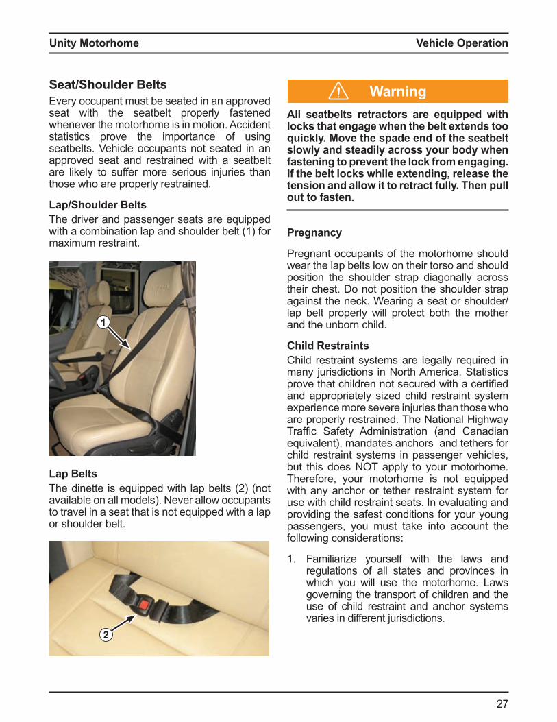
Lap Shoulder eltsThe driver and passenger seats are equipped with a combination lap and shoulder belt (1) for maximum restraint.
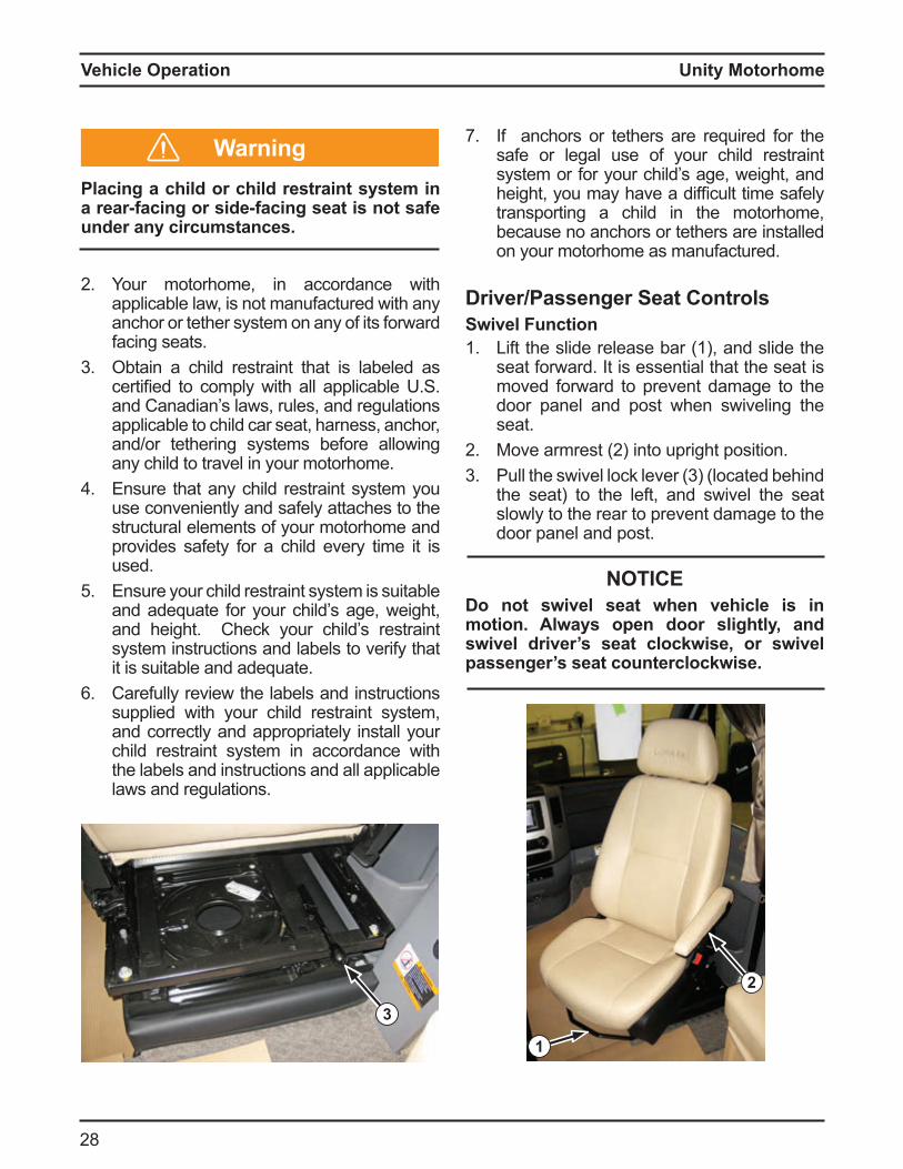
Lap eltsThe dinette is e uipped with lap elts 2 not available on all models). Never allow occupants to travel in a seat that is not equipped with a lap or shoulder belt.
1
2
ll seatbelts retractors are e uipped with loc s that engage when the belt e tends too
uic l . ove the spade end of the seatbelt slowl and steadil across our bod when fastening to prevent the lock from engaging. f the belt loc s while e tending release the tension and allow it to retract fully. Then pull out to fasten.
regnanc
Pregnant occupants of the motorhome should wear the lap belts low on their torso and should position the shoulder strap diagonally across their chest. Do not position the shoulder strap against the neck. Wearing a seat or shoulder/lap belt properly will protect both the mother and the unborn child.
Child RestraintsChild restraint systems are legally required in many jurisdictions in North America. Statistics prove that children not secured with a certified and appropriately sized child restraint system experience more severe injuries than those who are properly restrained. The National Highway Tra fic Sa ety d inistration and Canadian equivalent), mandates anchors and tethers for child restraint systems in passenger vehicles, but this does NOT apply to your motorhome. Therefore, your motorhome is not equipped with any anchor or tether restraint system for use with child restraint seats. In evaluating and providing the safest conditions for your young passengers, you must take into account the following considerations:
1. Familiarize yourself with the laws and regulations of all states and provinces in which you will use the motorhome. Laws governing the transport of children and the use of child restraint and anchor systems varies in different jurisdictions.
Warning
Unity Motorhome
28
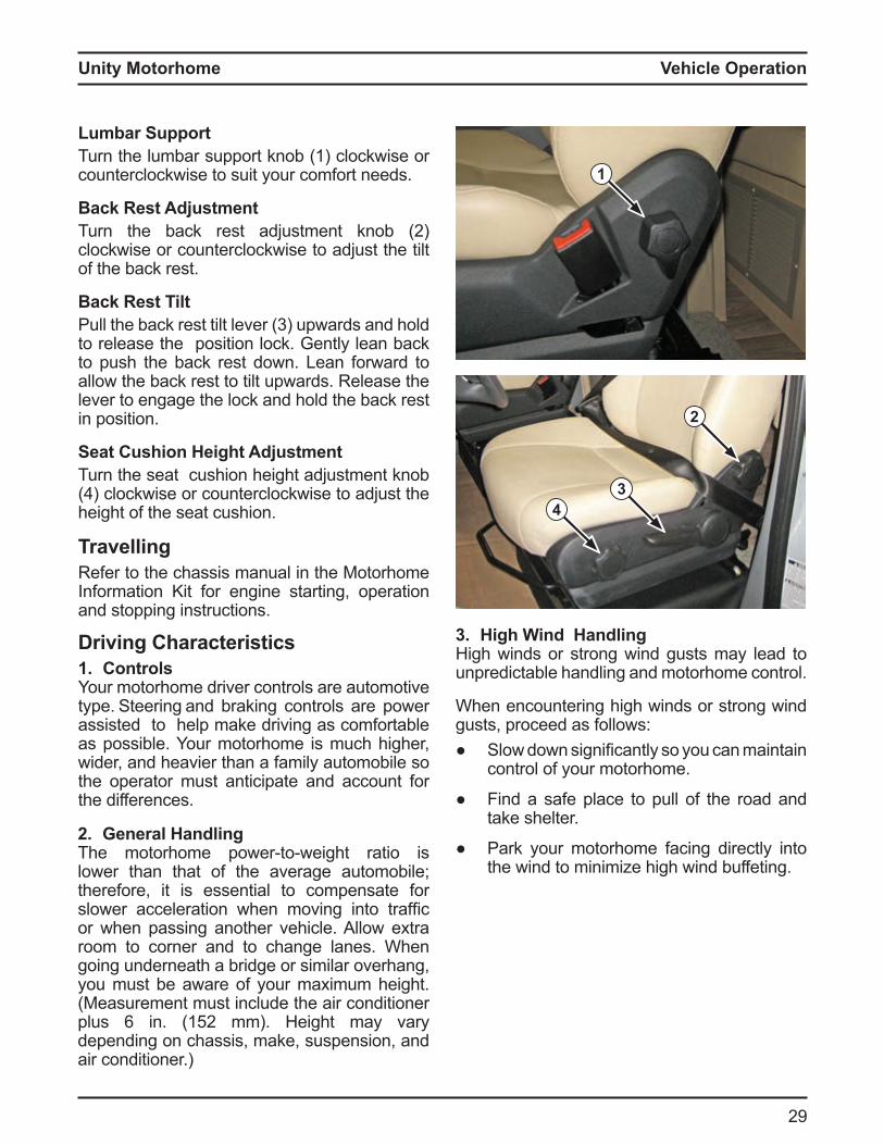
river assenger Seat ControlsSwivel Function1. Lift the slide release bar (1), and slide the
seat forward. It is essential that the seat is moved forward to prevent damage to the door panel and post when swiveling the seat.
2 ove ar rest 2 into upright position3 Pull the swivel lock lever 3 located ehind
the seat) to the left, and swivel the seat slowly to the rear to prevent damage to the door panel and post.
2
1
lacing a child or child restraint s stem in a rear-facing or side-facing seat is not safe under any circumstances.
2 Your motorhome, in accordance with applicable law, is not manufactured with any anchor or tether system on any of its forward facing seats.
3 Obtain a child restraint that is labeled as certified to co ply with all applica le S and Canadian’s laws, rules, and regulations applicable to child car seat, harness, anchor, and/or tethering systems before allowing any child to travel in your motorhome.
Ensure that any child restraint system you use conveniently and safely attaches to the structural elements of your motorhome and provides safety for a child every time it is used.
5 Ensure your child restraint system is suitable and adequate for your child’s age, weight, and height. Check your child’s restraint system instructions and labels to verify that it is suitable and adequate.
Carefully review the labels and instructions supplied with your child restraint system, and correctly and appropriately install your child restraint system in accordance with the labels and instructions and all applicable laws and regulations.
NOTICEDo not swivel seat when vehicle is in motion. Always open door slightly, and swivel driver’s seat clockwise, or swivel passenger’s seat counterclockwise.
3
Warning 7. If anchors or tethers are required for the safe or legal use of your child restraint system or for your child’s age, weight, and height, you ay have a di ficult ti e sa ely transporting a child in the motorhome, because no anchors or tethers are installed on your motorhome as manufactured.
Vehicle Operation
Unity Motorhome
29
Vehicle Operation
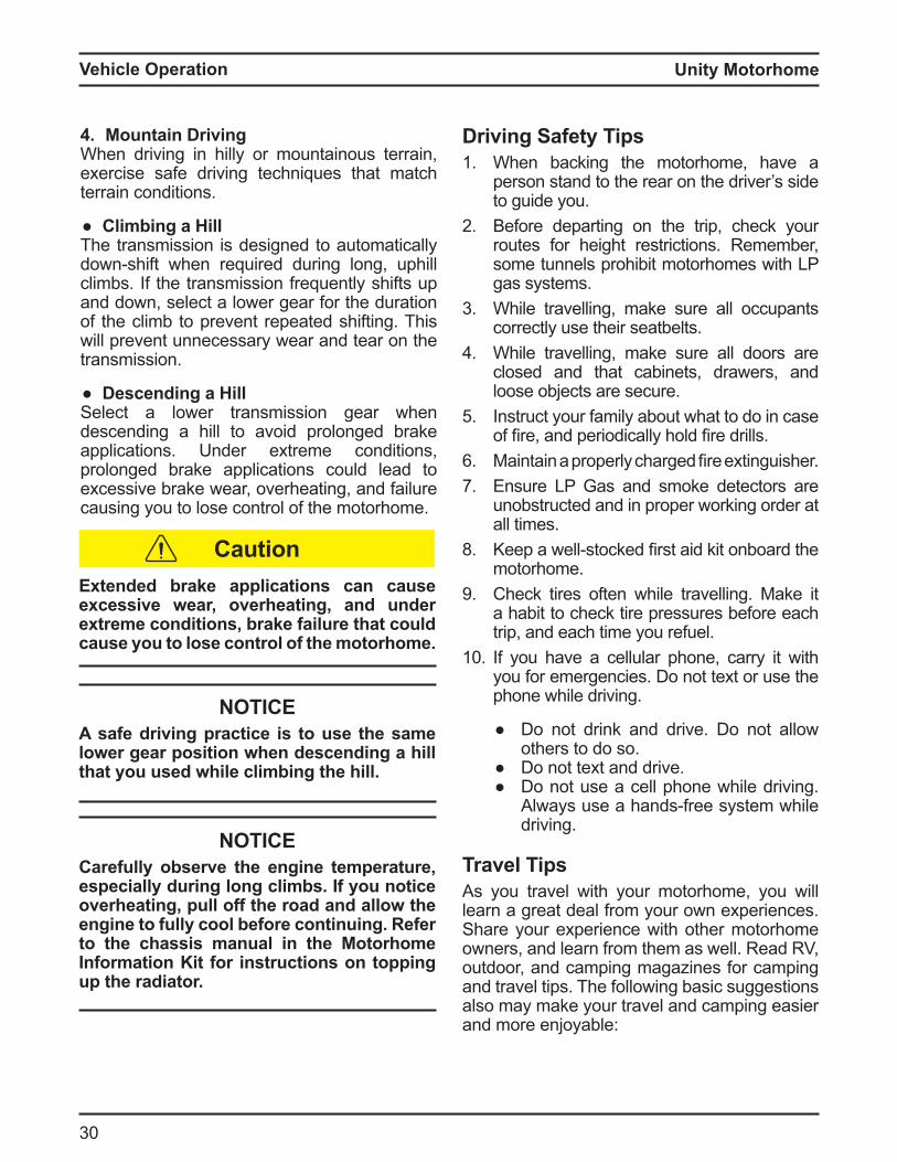
Lumbar SupportTurn the lumbar support knob (1) clockwise or counterclockwise to suit your comfort needs.
Back Rest AdjustmentTurn the ack rest ad ust ent kno 2 clockwise or counterclockwise to adjust the tilt of the back rest.
Back Rest TiltPull the ack rest tilt lever 3 upwards and hold to release the position lock. Gently lean back to push the back rest down. Lean forward to allow the back rest to tilt upwards. Release the lever to engage the lock and hold the back rest in position.
Seat Cushion Height AdjustmentTurn the seat cushion height adjustment knob
clockwise or counterclockwise to ad ust the height of the seat cushion.
1
43
TravellingRefer to the chassis manual in the Motorhome Information Kit for engine starting, operation and stopping instructions.
Driving Characteristics1. ControlsYour motorhome driver controls are automotive type. Steering and braking controls are power assisted to help make driving as comfortable as possible. Your motorhome is much higher, wider, and heavier than a family automobile so the operator must anticipate and account for the differences.
2. General HandlingThe otorho e power to weight ratio is lower than that of the average automobile; therefore, it is essential to compensate for slower acceleration when oving into tra fic or when passing another vehicle. Allow extra room to corner and to change lanes. When going underneath a bridge or similar overhang, you must be aware of your maximum height. (Measurement must include the air conditioner plus in 152 eight ay vary depending on chassis, make, suspension, and air conditioner.)
2
3. High Wind HandlingHigh winds or strong wind gusts may lead to unpredictable handling and motorhome control.
When encountering high winds or strong wind gusts, proceed as follows:
Slow down significantly so you can aintain control of your motorhome.
Find a safe place to pull of the road and take shelter.
Park your motorhome facing directly into the wind to minimize high wind buffeting.
Unity Motorhome
30
Vehicle Operation
NOTICECarefull observe the engine temperature especiall during long climbs. f ou notice overheating, pull off the road and allow the engine to full cool before continuing. efer to the chassis manual in the Motorhome Information Kit for instructions on topping up the radiator.
tended bra e applications can cause excessive wear, overheating, and under e treme conditions bra e failure that could cause you to lose control of the motorhome.
NOTICEA safe driving practice is to use the same lower gear position when descending a hill that ou used while climbing the hill.
4. Mountain DrivingWhen driving in hilly or mountainous terrain, exercise safe driving techniques that match terrain conditions.
Climbing a illThe transmission is designed to automatically down shi t when re uired during long, uphill climbs. If the transmission frequently shifts up and down, select a lower gear for the duration of the climb to prevent repeated shifting. This will prevent unnecessary wear and tear on the transmission.
Descending a HillSelect a lower transmission gear when descending a hill to avoid prolonged brake applications. Under extreme conditions, prolonged brake applications could lead to excessive brake wear, overheating, and failure causing you to lose control of the motorhome.
Driving Safety Tips1. When backing the motorhome, have a
person stand to the rear on the driver’s side to guide you.
2 Before departing on the trip, check your routes for height restrictions. Remember, some tunnels prohibit motorhomes with LP gas systems.
3 While travelling, make sure all occupants correctly use their seatbelts.
While travelling, make sure all doors are closed and that cabinets, drawers, and loose objects are secure.
5 Instruct your family about what to do in case o fire, and periodically hold fire drills
aintain a properly charged fire e tinguisher7. Ensure LP Gas and smoke detectors are
unobstructed and in proper working order at all times.
8. eep a well stocked first aid kit on oard the motorhome.
9 Check tires often while travelling. Make it a habit to check tire pressures before each trip, and each time you refuel.
10 If you have a cellular phone, carry it with you for emergencies. Do not text or use the phone while driving.
Do not drink and drive. Do not allow others to do so.
Do not text and drive. Do not use a cell phone while driving.
lways use a hands ree syste while driving.
Travel TipsAs you travel with your motorhome, you will learn a great deal from your own experiences. Share your experience with other motorhome owners, and learn from them as well. Read RV, outdoor, and camping magazines for camping and travel tips. The following basic suggestions also may make your travel and camping easier and more enjoyable:
Caution
Unity Motorhome
31
Vehicle Operation
1. Make sure all compartment, refrigerator, and freezer doors are closed securely. Carefully open these doors after travelling: the contents may have shifted while travelling and may fall when you open the door.
2 Know the height and width of your motorhome, and allow for adequate clearance.
3 Use your mirrors while driving to determine whether you are crowding the centre line or the outside edge of the highway. Remember, your motorhome requires a much different driving style than your family car.
When towing a vehicle, make sure the combined weight of the towed vehicle does not exceed the GCWR as stated on the vehicle certification la el located on the passenger door frame (US models only).
5 Check your route carefully before you travel. Some jurisdictions prohibit vehicles with LP gas containers to drive through highway tunnels.
Fill your water tank with clean, fresh, potable water only o not use a new hose to fill the tank–it may leave a taste of rubber or vinyl.
7. Conserve water, especially when showering. The holding tanks have a limited capacity.
8. Dump sewage only at approved dumping sites.
9 Store all liquids in plastic containers with tight seals.
10 Watch the levels in your holding tanks. Dump regularly to avoid unnecessary buildup and potential odor. After dumping, add water to the black water tank to prevent solids from settling in the tank. Without adequate liquid in the black water tank, dumping can be di ficult or i possi le
11. e care ul not to leave odor causing ood or materials in your motorhome for extended periods of time. Make sure wet clothing and towels are fully dried before storing.
12 ake sure your fire e tinguisher is ready or use and that you know how to operate it.
Severe Weather InformationAs a motorhome traveler, you may want to e plore new and out o the way places These recreational areas can be vulnerable to unusual and severe weather conditions. The following suggestions and safety precautions may help you in case you find yoursel in severe weather situations.
NOTICEll motorhome occupants must be familiar
with these safety precautions and should be alert to changing weather.
1. Be alert. Thunderstorms and heavy rains can occur suddenly and unexpectedly. Frequently check weather reports for the area in which you are camping or travelling so you will not be caught unaware of sudden weather changes.
2 Remember the following terms: Weather Watch Severe weather ay
develop in your area. Be prepared for an emergency.
Weather Warning Severe weather is occurring or is imminent. Immediately find a sa e location
3 When camping near a body of water, leave plenty of space and elevation between your motorhome and the water.
Avoid canyons or dry washes during threatening weather. Prepare an alternate exit, and move to higher ground as soon as it starts raining.
5 you get caught in a ash ood, do not attempt to move your vehicle. Abandon it, and return only after the water level has subsided. Never attempt to drive through any ooded area
Comply with all warnings and instructions provided by local authorities.
7. Stock enough survival supplies for several days This should include ood, water, first aid supplies, and necessary medications.
Unity Motorhome
32
8. When you leave home, inform someone of your destination and your schedule. Notify the same person if your plans change.
Emergencies While DrivingYour motorhome is designed with features that allow the driver and occupants to resolve emergencies or failures while travelling. Review this section to become familiar with the recommended procedures to resolve these conditions or situations. Review this section with all new drivers and before each trip.
azard Warning LightsYour motorhome is equipped with a hazard warning light system. Both the front and rear turn signals ash in unison when the syste is turned on. Refer to the chassis manual in the Motorhome Information Kit for additional details and location of the hazard warning lights.
Activate the hazard warning lights whenever the motorhome is stopped on the side of a roadway or near oving tra fic The ha ard war ing lights alert other motorists of a potential hazard and to take extra care. The system is designed so the lights continue ashing when the switch is on, even if the key is in the off position or removed from the ignition.
Flat Tire you have a at tire while operating your otorho e, slow down gradually to prevent
loss of control, and pull to the shoulder or the side of the road. Stop on a level paved surface and engage the parking brake. Refer to the ollowing steps to change the at tire
1. Turn on the hazard warning lights.2 Place wheel chocks in front and rear of tire
located on the opposite side o the at tire3 ediately contact a ualified roadside
repair service because your motorhome is not equipped with a spare tire.
If a roadside service is unavailable, inspect the at tire to deter ine whether you can service or repair it.
5 you can service or repair the at tire, you must raise the vehicle using the jack.
NOTICEAttempting to pull or tow the motorhome to start may result in major drivetrain component failure or damage.
Consult the chassis manual in the Motorhome Information Kit to locate the jack and to determine the proper jack placement locations on the chassis.
7. If the ground is soft or unstable, carefully move the motorhome to a safe location before attempting to lift with the jack.
8. Use a jacking board for stability on loose or soft ground.
9 Raise the motorhome with the jack according to the instructions in the chassis manual.
10 Never allow any portion of anyone’s body to be under the vehicle at any time while raising or supporting the motorhome with the jack.
11. Before resuming travel with a new or repaired tire, ensure the lug nuts are tightened in the proper se uence and to the tor ue specified in the chassis manual. Use a torque wrench to ensure the specified tor ue is achieved Recheck and retorque the wheel lug nuts a ter 25 and 100 iles 0 and 1 0 k o operation.
When the Vehicle is isabled12 Emergency Starting: Do not push or tow
the motorhome in an attempt to start it. The powertrain is not designed to transmit torque to turn the engine over for starting.
Vehicle Operation
13 Jump Starting/Boosting: Refer to the chassis manual in the Motorhome Instruction Kit for instructions.
1 Break Down: If the motorhome breaks down on the roadway, pull off the road and stop, engage the parking brake, turn on the hazard warning lights, and chock the wheels if you are on uneven or unstable ground. Call an approved towing service, and provide them with the vehicle make, weight, length, width, and height to ensure they dispatch an appropriately sized truck to tow your
otorho e to a ualified repair acility
Unity Motorhome
33
Vehicle Operation
NOTICE OOS W Consult
the chassis manual in the Motorhome Information Kit for proper jump starting/boosting procedures.
NOTICElwa s set the par ing bra e and place
wheel chocks in front and rear of wheels to prevent unexpected movement.
OverheatingIf the engine overheats while driving, follow these steps:
1. Pull to the side of the road and stop immediately.
2 Shut off the engine.3 Check coolant level in the coolant recovery
tank. The coolant level should be between the ull and add arks on the tank
If the coolant level is low, proceed as follows: Check for visible leaks from the hose
connections, radiator, and water pump. Make sure the belts are tight and the
cooling fan is turning. If coolant level is low, add coolant to the
recovery tank as soon as possible. If the coolant is leaking, the fan belt is
loose or broken, or the red warning light stays on, do NOT start the engine until the problem is corrected.
5 Once the temperature gauge returns to normal, resume driving, and keep an eye on the gauge. Do NOT resume driving until the problem has been corrected and the temperature has returned to normal.
ar ing1. ar ing
You can stop and park your motorhome much like an automobile; however, always remember that the unit is longer, wider, and higher than a typical automobile and requires more room and clearance.
1. Backing Up Using Mirrors
Large mirrors are mounted on both sides of your motorhome to provide rearward visibility for the driver. They do not provide visibility directly behind or on top (clearance) of the unit, however.
Using Spotters For best results, have another person help guide the driver while backing. The driver and spotter should agree to the meaning of hand signals before starting the backing process. The spotter should always be in a position that is visible to the driver while backing.

Unity Motorhome
3
3
Do NOT take your eyes off the road for extended periods of time or a crash causing injury or death could result. Do NOT give extended attention to the in-dash entertainment system while driving.
Extended OccupancyYour motorhome is designed for recreational and sort ter occupancy n case o e tended occupancy, there are a few things to keep in mind regarding humidity and condensation. Excessive moisture released inside the motorhome can cause water stains and mildew on the upholstery, wall materials, and woodwork. Moisture condensing on the windows is an indication that the humidity inside your motorhome is too high. The following procedures will help to reduce the moisture level inside your motorhome:
1. Open windows and vents. This will allow resh air to ow through your otorho e and reduce moisture levels.
2 Reduce the amount of moisture released inside the motorhome. Run the bathroom fan when using the bathroom, and turn on the roof vent fan while cooking to help remove excessive moisture from your motorhome. Do not hang wet towels or swimwear inside the motorhome to dry.
Leveling the otorhomeLevel the motorhome frame before using any of the appliances. The refrigerator is especially sensitive and must be level to function properly. Spend the necessary time to level your motorhome to ensure maximum enjoyment and reliability of your appliances. Select the area to park your vehicle as follows:
1. Inspect the area you want to park your motorhome. Select an area that has a fir , prepared sur ace ost ca pgrounds provide this type of parking area for motorhomes.
2 Select an area that is level, or as close to level, as possible.
3 se a carpenter s level on the oor to determine the locations where it is necessary to place blocks in order to level the motorhome.
Level ro side to side first, then ro ront to back. To raise one side of the motorhome, place planks in front of the low side tire, and drive the motorhome forward until the tires are resting on top of the planks.
2
1
Back-up Monitoring System Your motorhome is equipped with a rear camera monitoring system. The rear camera (1) view will automatically display on the in dash entertain ent syste display 2 when you shi t the vehicle into reverse, or when you press and hold the S S utton 3 , and will re ain visi le or appro i ately fi teen seconds after shifting the motorhome out of reverse. Push any button on the in dash entertain ent syste to instantly exit rear camera view. For complete operating instructions, refer to the chassis manual in your Motorhome Information Kit.
Caution
Vehicle Operation
Unity Motorhome
35
Vehicle Operation
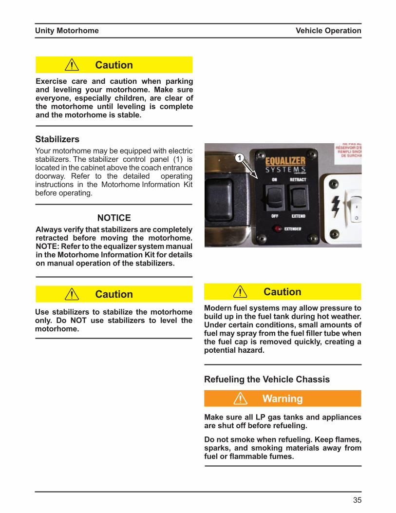
StabilizersYour motorhome may be equipped with electric stabilizers. The stabilizer control panel (1) is located in the cabinet above the coach entrance doorway. Refer to the detailed operating instructions in the Motorhome Information Kit before operating.
Refueling the Vehicle Chassis
Exercise care and caution when parking and leveling your motorhome. Make sure everyone, especially children, are clear of the motorhome until leveling is complete and the motorhome is stable.
1
NOTICElwa s verif that stabilizers are completel
retracted before moving the motorhome. O efer to the e ualizer s stem manual
in the Motorhome Information Kit for details on manual operation of the stabilizers.
se stabilizers to stabilize the motorhome onl . o O use stabilizers to level the motorhome.
a e sure all L gas tan s and appliances are shut off before refueling.
o not smo e when refueling. eep ames sparks, and smoking materials away from fuel or ammable fumes.
Modern fuel systems may allow pressure to build up in the fuel tan during hot weather. Under certain conditions, small amounts of fuel ma spra from the fuel filler tube when the fuel cap is removed quickly, creating a potential hazard.
Warning
Caution
CautionCaution
Unity Motorhome
3
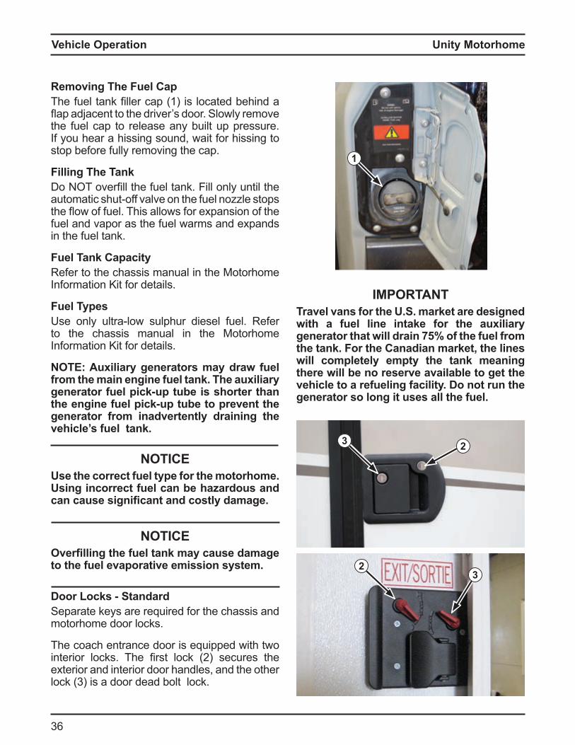
Removing The Fuel CapThe uel tank filler cap 1 is located ehind a ap ad acent to the driver s door Slowly re ove
the fuel cap to release any built up pressure. If you hear a hissing sound, wait for hissing to stop before fully removing the cap.
Filling The Tanko T overfill the uel tank ill only until the
auto atic shut o valve on the uel no le stops the ow o uel This allows or e pansion o the fuel and vapor as the fuel warms and expands in the fuel tank.
Fuel Tank CapacityRefer to the chassis manual in the Motorhome Information Kit for details.
Fuel Typesse only ultra low sulphur diesel uel Re er
to the chassis manual in the Motorhome Information Kit for details.
O u iliar generators ma draw fuel from the main engine fuel tank. The auxiliary generator fuel pic up tube is shorter than the engine fuel pic up tube to prevent the generator from inadvertently draining the vehicle’s fuel tank.
NOTICEUse the correct fuel type for the motorhome.
sing incorrect fuel can be hazardous and can cause significant and costl damage.
NOTICEOverfilling the fuel tan ma cause damage to the fuel evaporative emission system.
oor Loc s StandardSeparate keys are required for the chassis and motorhome door locks.
The coach entrance door is equipped with two interior locks The first lock 2 secures the exterior and interior door handles, and the other lock 3 is a door dead olt lock
1
32
OTravel vans for the U.S. market are designed with a fuel line intake for the auxiliary generator that will drain 75% of the fuel from the tank. For the Canadian market, the lines will completely empty the tank meaning there will be no reserve available to get the vehicle to a refueling facility. Do not run the generator so long it uses all the fuel.
23
Vehicle Operation
Unity Motorhome
37
Vehicle Operation
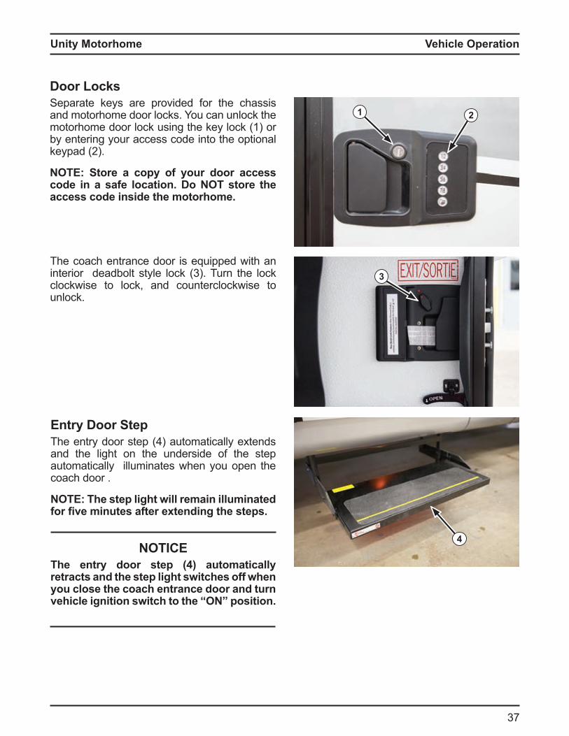
The coach entrance door is equipped with an interior dead olt style lock 3 Turn the lock clockwise to lock, and counterclockwise to unlock.
3
4
Entry Door StepThe entry door step auto atically e tends and the light on the underside of the step automatically illuminates when you open the coach door .
O he step light will remain illuminated for five minutes after e tending the steps.
NOTICEThe entry door step (4) automatically retracts and the step light switches off when you close the coach entrance door and turn vehicle ignition switch to the O position.
oor Loc sSeparate keys are provided for the chassis and motorhome door locks. You can unlock the motorhome door lock using the key lock (1) or by entering your access code into the optional keypad 2
O Store a cop of our door access code in a safe location. Do NOT store the access code inside the motorhome.
21

Unity Motorhome
38
6
7
Step Override SwitchDepress the top of the step override switch (1), located inside the coach entrance, to prevent the steps from retracting when the coach door is closed.
O he vehicle ignition switch must be in the O position for the step override switch (1) to work.nterior Overhead Light immer Switch
Turn di er switch 2 to turn on the interior overhead lights. Rotate the dimmer switch to control the interior light level. Turn the dimmer switch back to turn off the lights.
terior nterior Light Switchesepress the top o switch 3 to turn on the
exterior patio, assist handle and entrance step ground illumination lights.
epress the top o switch to turn on the interior accent lights.
epress the top o switch 5 to turn on the exterior storage and utility center lights.
NOTICEurn the batter disconnect switch to
internal 12 volt DC power to operate the interior roof lights. Refer to the “Electrical S stem Operation chapter in this manual for batter disconnect switch details.
nder Cabinet Light Switchesnder ca inet lights are controlled y
adjacent switches (7).
13
2
4
5
6
Vehicle Operation
Unity Motorhome
39
Vehicle Operation
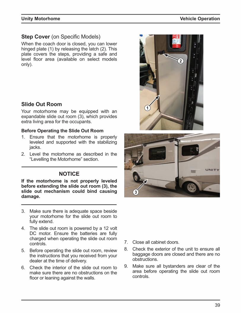
Step Cover on Specific odelsWhen the coach door is closed, you can lower hinged plate 1 y releasing the latch 2 This plate covers the steps, providing a safe and level oor area availa le on select odels only).
2
1Slide Out RoomYour motorhome may be equipped with an e panda le slide out roo 3 , which provides extra living area for the occupants.
Before Operating the Slide Out Room1. Ensure that the motorhome is properly
leveled and supported with the stabilizing jacks.
2 Level the motorhome as described in the Levelling the otorho e section
NOTICEIf the motorhome is not properly leveled before e tending the slide out room 3 the slide out mechanism could bind causing damage.
3 Make sure there is adequate space beside your motorhome for the slide out room to fully extend.
The slide out roo is powered y a 12 volt DC motor. Ensure the batteries are fully charged when operating the slide out room controls.
5 Before operating the slide out room, review the instructions that you received from your dealer at the time of delivery.
Check the interior of the slide out room to make sure there are no obstructions on the oor or leaning against the walls
7. Close all cabinet doors.8. Check the exterior of the unit to ensure all
baggage doors are closed and there are no obstructions.
9 Make sure all bystanders are clear of the area before operating the slide out room controls.
3
Unity Motorhome
0
2
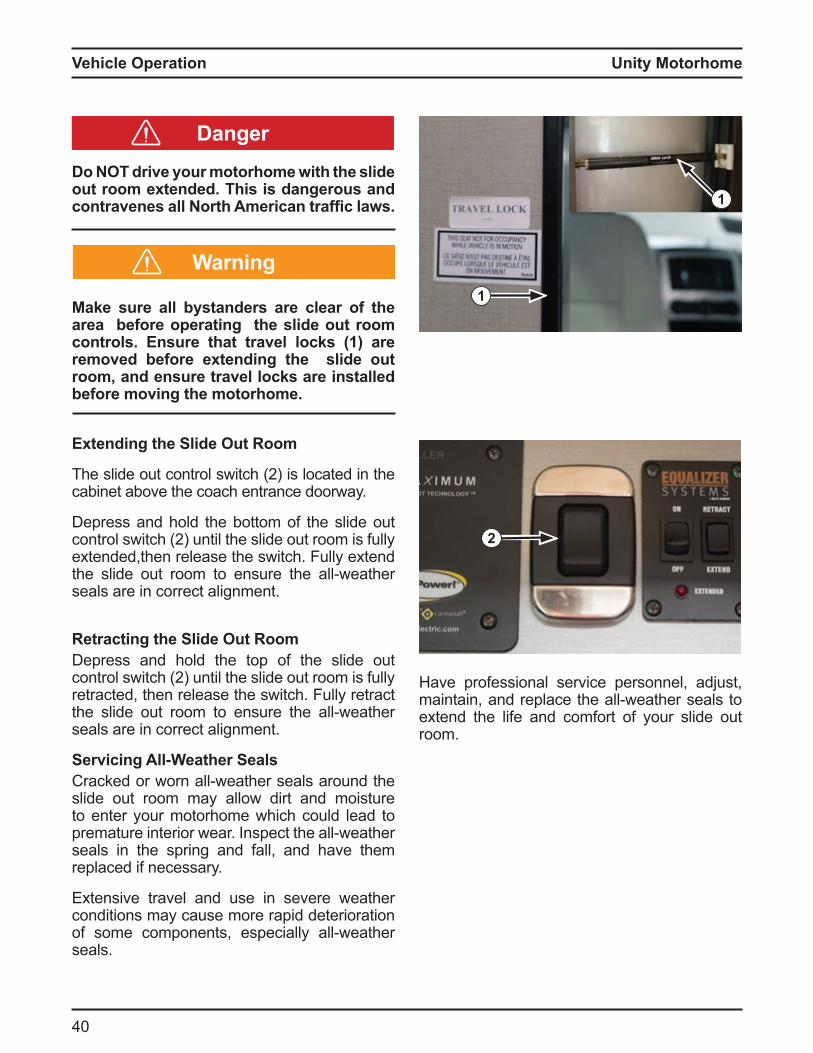
Do NOT drive your motorhome with the slide out room extended. This is dangerous and contravenes all orth merican traffic laws.
a e sure all b standers are clear of the area before operating the slide out room controls. Ensure that travel locks (1) are removed before e tending the slide out room, and ensure travel locks are installed before moving the motorhome.
Extending the Slide Out Room
The slide out control switch 2 is located in the cabinet above the coach entrance doorway.
Depress and hold the bottom of the slide out control switch 2 until the slide out roo is ully extended,then release the switch. Fully extend the slide out roo to ensure the all weather seals are in correct alignment.
Retracting the Slide Out RoomDepress and hold the top of the slide out control switch 2 until the slide out roo is ully retracted, then release the switch. Fully retract the slide out roo to ensure the all weather seals are in correct alignment.
Servicing All-Weather SealsCracked or worn all weather seals around the slide out room may allow dirt and moisture to enter your motorhome which could lead to pre ature interior wear nspect the all weather seals in the spring and fall, and have them replaced if necessary.
Extensive travel and use in severe weather conditions may cause more rapid deterioration o so e co ponents, especially all weather seals.
1
Warning
Danger
Have professional service personnel, adjust, aintain, and replace the all weather seals to
extend the life and comfort of your slide out room.
1
Vehicle Operation
Unity Motorhome
1
Vehicle Operation
A B
C
4
1
3 2
5
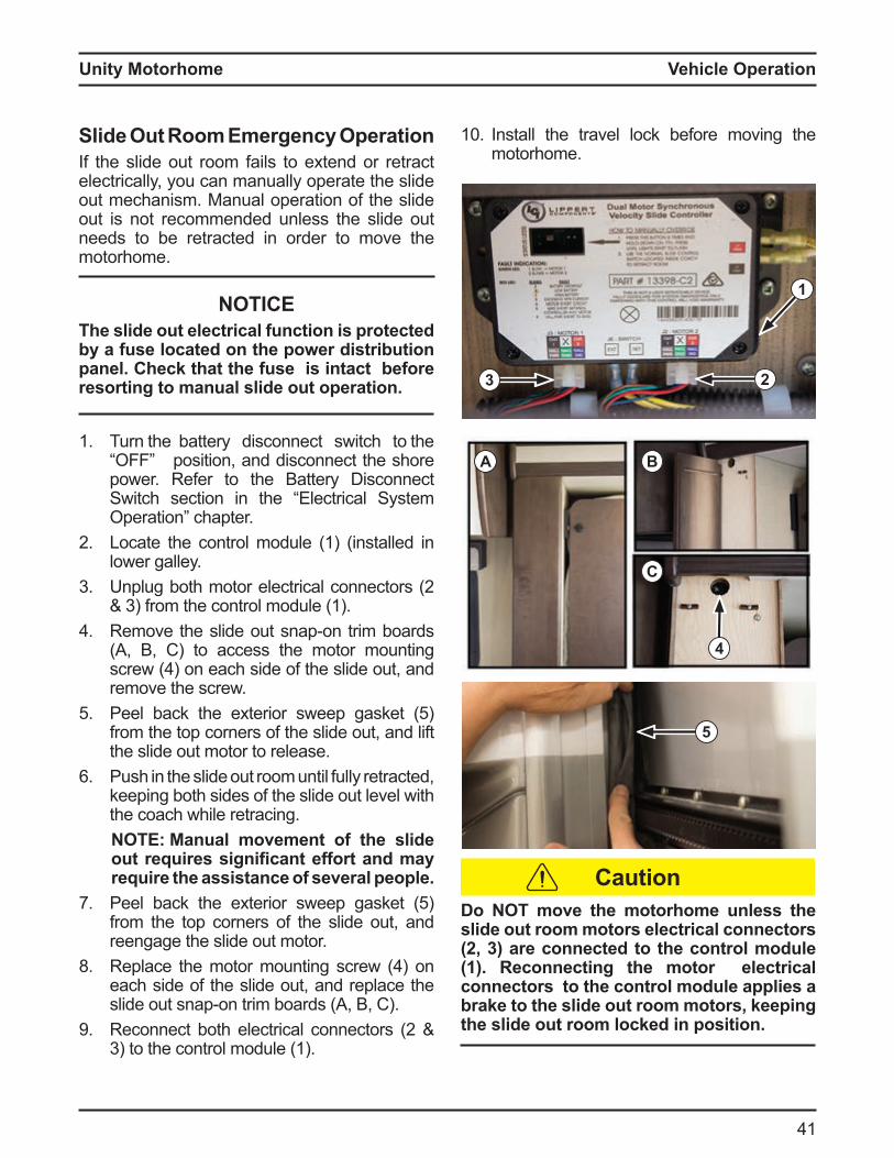
Slide Out Room Emergency OperationIf the slide out room fails to extend or retract electrically, you can manually operate the slide out mechanism. Manual operation of the slide out is not recommended unless the slide out needs to be retracted in order to move the motorhome.
NOTICEThe slide out electrical function is protected b a fuse located on the power distribution panel. Chec that the fuse is intact before resorting to manual slide out operation.
1. Turn the battery disconnect switch to the position, and disconnect the shore
power. Refer to the Battery Disconnect Switch section in the “Electrical System
peration chapter2 Locate the control module (1) (installed in
lower galley.3 nplug oth otor electrical connectors 2
3 ro the control odule 1 Re ove the slide out snap on tri oards
(A, B, C) to access the motor mounting screw on each side o the slide out, and remove the screw.
5 Peel ack the e terior sweep gasket 5 from the top corners of the slide out, and lift the slide out motor to release.
Push in the slide out room until fully retracted, keeping both sides of the slide out level with the coach while retracing.
O anual movement of the slide out re uires significant effort and ma require the assistance of several people.
7. Peel ack the e terior sweep gasket 5 from the top corners of the slide out, and reengage the slide out motor.
8. Replace the otor ounting screw on each side of the slide out, and replace the slide out snap on tri oards , , C
9 Reconnect oth electrical connectors 2 3 to the control odule 1
Do NOT move the motorhome unless the slide out room motors electrical connectors (2, 3) are connected to the control module (1). Reconnecting the motor electrical connectors to the control module applies a bra e to the slide out room motors eeping the slide out room locked in position.
10 Install the travel lock before moving the motorhome.
Caution
Unity Motorhome
2
1
2
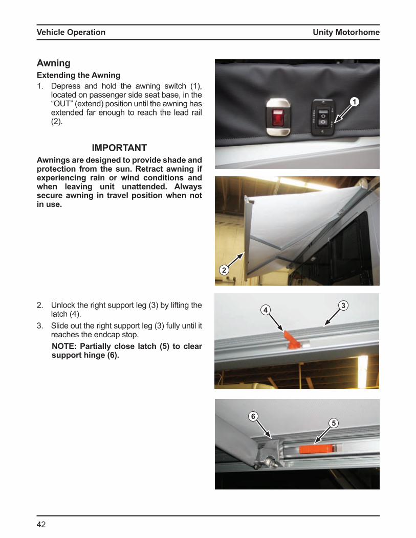
AwningExtending the Awning1. Depress and hold the awning switch (1),
located on passenger side seat base, in the T e tend position until the awning has
extended far enough to reach the lead rail 2
OAwnings are designed to provide shade and protection from the sun. Retract awning if experiencing rain or wind conditions and when leaving unit unattended. Always secure awning in travel position when not in use.
2 nlock the right support leg 3 y li ting the latch
3 Slide out the right support leg 3 ully until it reaches the endcap stop.
O artiall close latch to clear support hinge (6).
34
56
Vehicle Operation
Unity Motorhome
3
Vehicle Operation
1
2
3
4
5
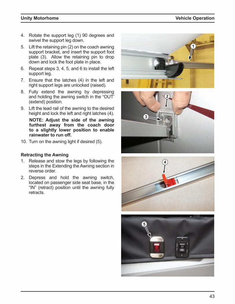
Rotate the support leg 1 90 degrees and swivel the support leg down.
5 Li t the retaining pin 2 on the coach awning support bracket, and insert the support foot plate 3 llow the retaining pin to drop down and lock the foot plate in place.
Repeat steps 3, , 5, and to install the le t support leg.
7. nsure that the latches in the le t and right support legs are unlocked (raised).
8. Fully extend the awning by depressing and holding the awning switch in the “OUT’ (extend) position.
9 Lift the lead rail of the awning to the desired height and lock the le t and right latches
O d ust the side of the awning furthest away from the coach door to a slightl lower position to enable rainwater to run off.
10 Turn on the awning light i desired 5
Retracting the Awning1. Release and stow the legs by following the
steps in the Extending the Awning section in reverse order.
2 Depress and hold the awning switch, located on passenger side seat base, in the
retract position until the awning ully retracts.

Unity Motorhome
Operating the RefrigeratorPress and hold the power utton to turn the refrigerator on and off. The display panel will illuminate when the refrigerator is operating, and the display panel lights will shut off when the refrigerator power is off.
Refer to the refrigerator owner’s manual in the Motorhome Information Kit for detailed operating instructions.
O he refrigerator is self starting in all operating modes.
14 2 3
Appliance & Equipment OperationAppliance and equipment may vary according to your otorho e odel, specifications, and oor plan Re er to the otorho e Information Kit for operation and maintenance details relating to the specific appliances and equipment installed in your motorhome.
RefrigeratorThe refrigerator in your motorhome operates in the following modes:
1. 120 volt C electric2 LP gas with 12 volt C ignition3 12 volt C
NOTICEhe motorhome S be completel level
for the refrigerator to operate properly and safely.
Operating the refrigerator with the motorhome parked on unlevel ground could result in permanent damage to the appliance.
Parking and levelling the motorhome for comfortable living will usually place the refrigerator within satisfactory level limits. Use a level to ensure the motorhome is within a couple degrees of level.If the refrigerator is unused for an extended period of time, make sure it is emptied, switched off, defrosted, cleaned, and left with the door ajar. Use the travel latch to lock the door in the ajar position.
O Leaving the door slightl open allows air to circulate and prevents the build up of odor or mold.
o O store e plosive substances in the refrigerator such as lighter uid petrol ether, etc.
Caution
Caution
Vehicle Operation
Unity Motorhome
5
Appliance & Equipment Operation
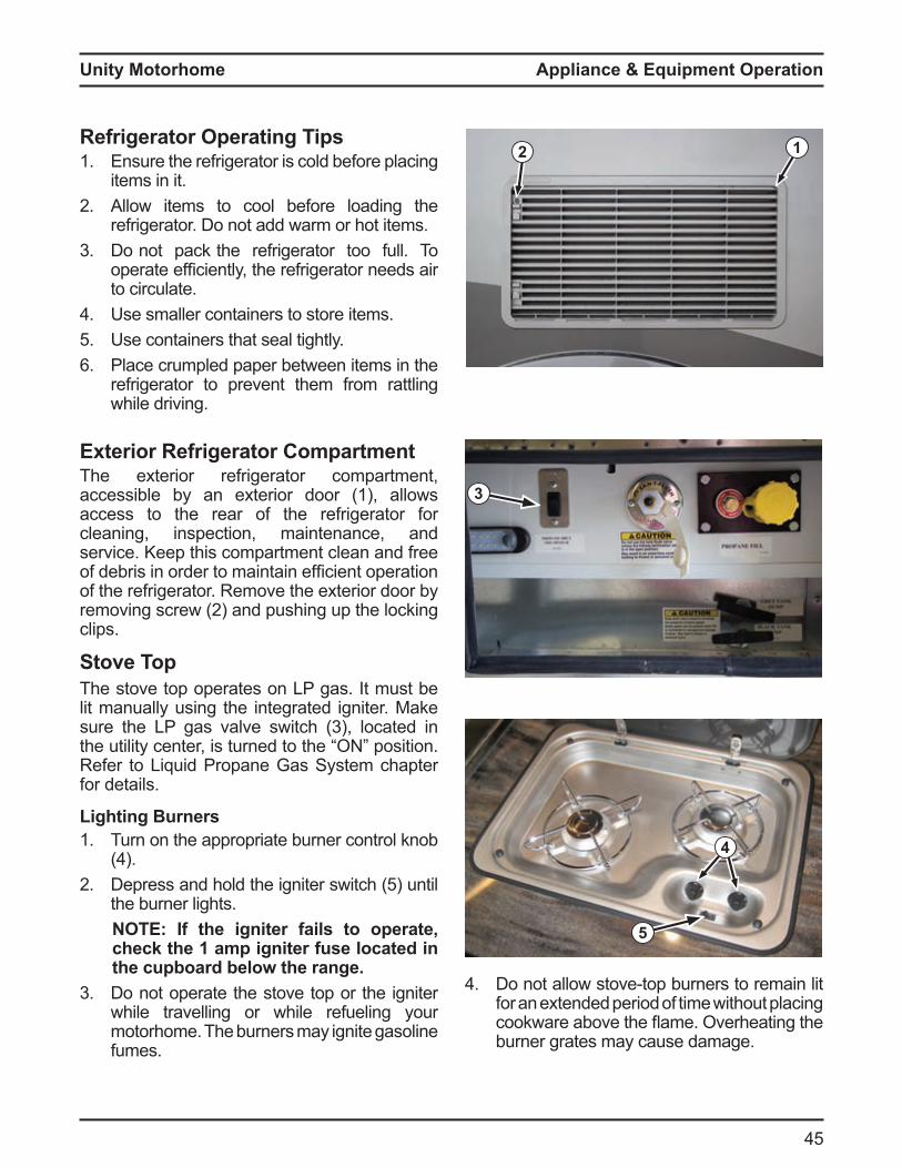
Refrigerator Operating Tips1. Ensure the refrigerator is cold before placing
items in it.2 Allow items to cool before loading the
refrigerator. Do not add warm or hot items.3 Do not pack the refrigerator too full. To
operate e ficiently, the re rigerator needs air to circulate.
Use smaller containers to store items.5 Use containers that seal tightly.
Place crumpled paper between items in the refrigerator to prevent them from rattling while driving.
Exterior Refrigerator CompartmentThe exterior refrigerator compartment, accessible by an exterior door (1), allows access to the rear of the refrigerator for cleaning, inspection, maintenance, and service. Keep this compartment clean and free o de ris in order to aintain e ficient operation of the refrigerator. Remove the exterior door by re oving screw 2 and pushing up the locking clips.
Stove TopThe stove top operates on LP gas. It must be lit manually using the integrated igniter. Make sure the LP gas valve switch 3 , located in the utility center, is turned to the position Refer to Liquid Propane Gas System chapter for details.
12
3
4
5
Lighting urners1. Turn on the appropriate burner control knob
2 epress and hold the igniter switch 5 until the burner lights.
O f the igniter fails to operate check the 1 amp igniter fuse located in the cupboard below the range.
3 Do not operate the stove top or the igniter while travelling or while refueling your motorhome. The burners may ignite gasoline fumes.
o not allow stove top urners to re ain lit for an extended period of time without placing cookware a ove the a e verheating the burner grates may cause damage.
Unity Motorhome
5 Turn on the roof vent and open a window to ensure proper ventilation when operating the stove top.
Do not remove the warning label on the stove top lid
7. Do not operate burners with glass lid closed.
NOTICEever use the stove top burners to heat the
interior of your motorhome. Adhere to the warning labels in the coo ing area. lwa s make sure you have adequate ventilation when operating the burners.Light the burner immediatel after turning on the burner control nob to prevent a gas build up. cess gas can cause a are up when lit.
Microwave/Convection OvenOperating the Microwave/Convection OvenRefer to the microwave/convection oven manual in the Motorhome Information Kit for detailed operating and sa ety instructions specific to your unit.
Microwave/Convection Oven Operating Tips1. Do not attempt to operate the oven with
the door open. This may result in harmful exposure to microwave energy.
2 Do not defeat or tamper with the safety interlocks.
3 Do not place any object between the oven front face and the door or allow cleaner residue to accumulate on sealing surfaces.
Do not operate the oven if it is damaged. Do not operate the oven if there is damage to the door hinges, latches, seals, or sealing surfaces. Do not operate the oven if the door does not close properly or is bent.
5 Do not adjust or repair the oven door. ave the unit serviced y ualified service
personnel if necessary. Do not operate the oven when empty.
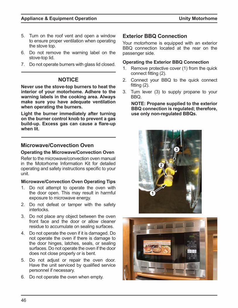
Exterior BBQ ConnectionYour motorhome is equipped with an exterior BBQ connection located at the rear on the passenger side.
Operating the Exterior BBQ Connection1. Remove protective cover (1) from the quick
connect fitting 22 Connect your BBQ to the quick connect
fitting 23 Turn lever 3 to supply propane to your
BBQ.O ropane supplied to the e terior
BBQ connection is regulated; therefore, use only non-regulated BBQs.
1
2
3
Appliance & Equipment Operation

Unity Motorhome
7
Appliance & Equipment Operation
L as urnaceOperating the L as urnaceThe LP gas urnace is controlled y the singlezone thermostat (1) located in the coach living area.
1L as urnace Operating ips
NOTICEDo NOT operate the furnace while the vehicle is moving.
1. ake sure the LP gas valve switch 3 , located in the rear utility center, is turned
Re er to the Li uid Propane Gas Syste chapter or details
2 Do not attempt to manually light the furnace–the furnace does not have a pilot light. It is ignited by a direct spark ignition system.
3 If the thermostat is set four degrees above the ambient room temperature, the blower will operate automatically.
O Simultaneousl hold the thermostat plus (+) and minus (-) buttons 2 to switch between C and .
If the burner fails to light, check the propane level at the system monitor panel to ensure there is propane in your tank. Refer to the Li uid Propane Gas Syste chapter or
details.5 If there is propane in the tank and the burner
fails to ignite, verify that the LP gas valve switch 3 is in the position
If there is propane in the tank and the LP gas valve switch 3 is on ut the urnace still fails to light, turn off the thermostat (1), turn off the LP gas valve switch, and contact your dealer or a local RV service center.
2
3
Before operating the thermostat, carefully read and follow the operating instructions in the L gas furnace manual located in the Motorhome Information Kit.
NOTICEDo NOT operate the furnace while the vehicle is moving.
lwa s set the thermostat fan to O mode before turning on heat.
Warning
Warning

Unity Motorhome
8
Refer to the air conditioner manual in the Motorhome Information Kit for detailed operating instructions.
1
oof ir Conditioner with eat umpThe roof air conditioner is controlled by the same coach thermostat that controls the furnace. Refer to LP Gas Furnace section for details. When the ther ostat is switched to the cool position and the temperature is set below the ambient room temperature, the air conditioner will operate automatically.
ir ow into the coach ca in can e controlled and directed by adjusting the roof vents (1).
Before operating the thermostat, carefully read and follow the operating instruction in the manual located in the Motorhome Information Kit.
3
eat umpThe air conditioner has a built in heat pump designed to take the chill out of the air. To turn on the heat pump, turn the thermostat to “Heat Pu p ode, and set the te perature 3 degrees above the ambient room temperature.
NOTICEThe air conditioner/heat pump operates only on 120 volt AC shoreline or generator power.
Maintaining the Roof Air Conditioner/Heat ump
Clean or change the air conditioner filter at least every two weeks when the air conditioner is in operation. Do not operate the air conditioner without installing the filter
Cleaning/Changing Filter1. Release the filter cover y re oving the
ounting olts 3 or depressing oth retainer clips 2
2 Re ove the filter and wash in war , soapy water ry the filter thoroughly e ore reinstalling the filter is e cessively dirty, replace with a new filter
1
Caution
3
4
2
4
4
Appliance & Equipment Operation
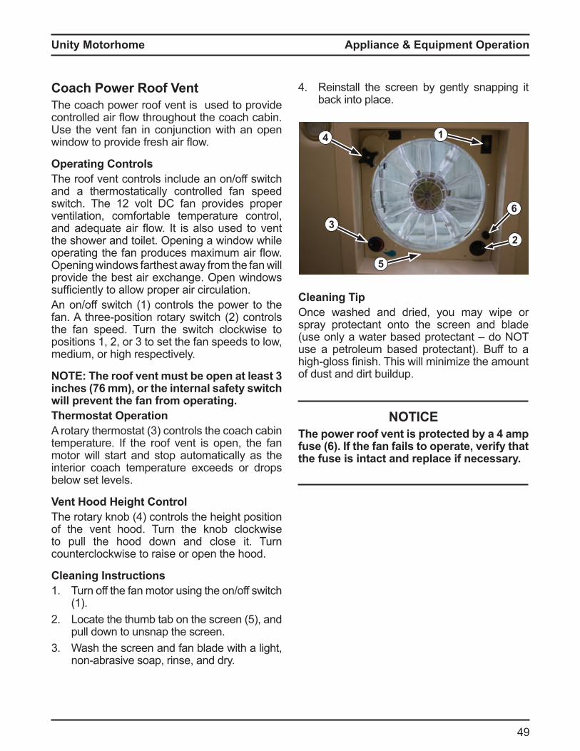
Unity Motorhome
9
Appliance & Equipment Operation
6
23
5
Cleaning TipOnce washed and dried, you may wipe or spray protectant onto the screen and blade (use only a water based protectant – do NOT use a petroleum based protectant). Buff to a high gloss finish This will ini i e the a ount of dust and dirt buildup.
NOTICEhe power roof vent is protected b a amp
fuse (6). If the fan fails to operate, verify that the fuse is intact and replace if necessary.
4 1
Coach ower oof VentThe coach power roof vent is used to provide controlled air ow throughout the coach ca in Use the vent fan in conjunction with an open window to provide resh air ow
Operating ControlsThe roof vent controls include an on/off switch and a thermostatically controlled fan speed switch The 12 volt C an provides proper ventilation, comfortable temperature control, and ade uate air ow t is also used to vent the shower and toilet. Opening a window while operating the an produces a i u air ow Opening windows farthest away from the fan will provide the best air exchange. Open windows su ficiently to allow proper air circulationAn on/off switch (1) controls the power to the an three position rotary switch 2 controls the fan speed. Turn the switch clockwise to positions 1, 2, or 3 to set the an speeds to low, medium, or high respectively.
O he roof vent must be open at least 3 inches (76 mm), or the internal safety switch will prevent the fan from operating.Thermostat Operation
rotary ther ostat 3 controls the coach ca in temperature. If the roof vent is open, the fan motor will start and stop automatically as the interior coach temperature exceeds or drops below set levels.
Vent Hood Height ControlThe rotary kno controls the height position of the vent hood. Turn the knob clockwise to pull the hood down and close it. Turn counterclockwise to raise or open the hood.
Cleaning Instructions1. Turn off the fan motor using the on/off switch
(1).2 Locate the thu ta on the screen 5 , and
pull down to unsnap the screen.3 Wash the screen and fan blade with a light,
non a rasive soap, rinse, and dry
Reinstall the screen by gently snapping it back into place.
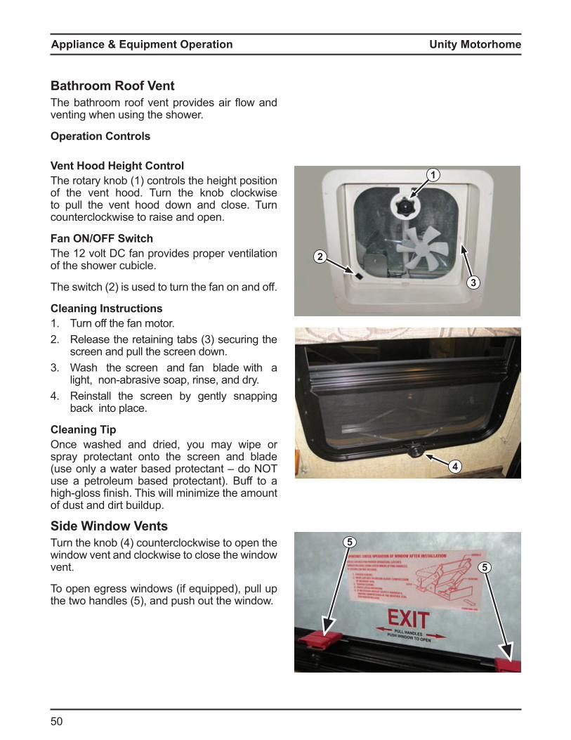
Unity Motorhome
50
1
2
3
4
Bathroom Roof VentThe athroo roo vent provides air ow and venting when using the shower.
Operation Controls
Vent Hood Height ControlThe rotary knob (1) controls the height position of the vent hood. Turn the knob clockwise to pull the vent hood down and close. Turn counterclockwise to raise and open.
Fan ON/OFF SwitchThe 12 volt C an provides proper ventilation of the shower cubicle.
The switch 2 is used to turn the an on and o
Cleaning Instructions1. Turn off the fan motor.2 Release the retaining ta s 3 securing the
screen and pull the screen down.3 Wash the screen and fan blade with a
light, non a rasive soap, rinse, and dry Reinstall the screen by gently snapping
back into place.
Cleaning TipOnce washed and dried, you may wipe or spray protectant onto the screen and blade (use only a water based protectant – do NOT use a petroleum based protectant). Buff to a high gloss finish This will ini i e the a ount of dust and dirt buildup.
Side Window VentsTurn the kno counterclockwise to open the window vent and clockwise to close the window vent.
To open egress windows (if equipped), pull up the two handles 5 , and push out the window
5
5
Appliance & Equipment Operation
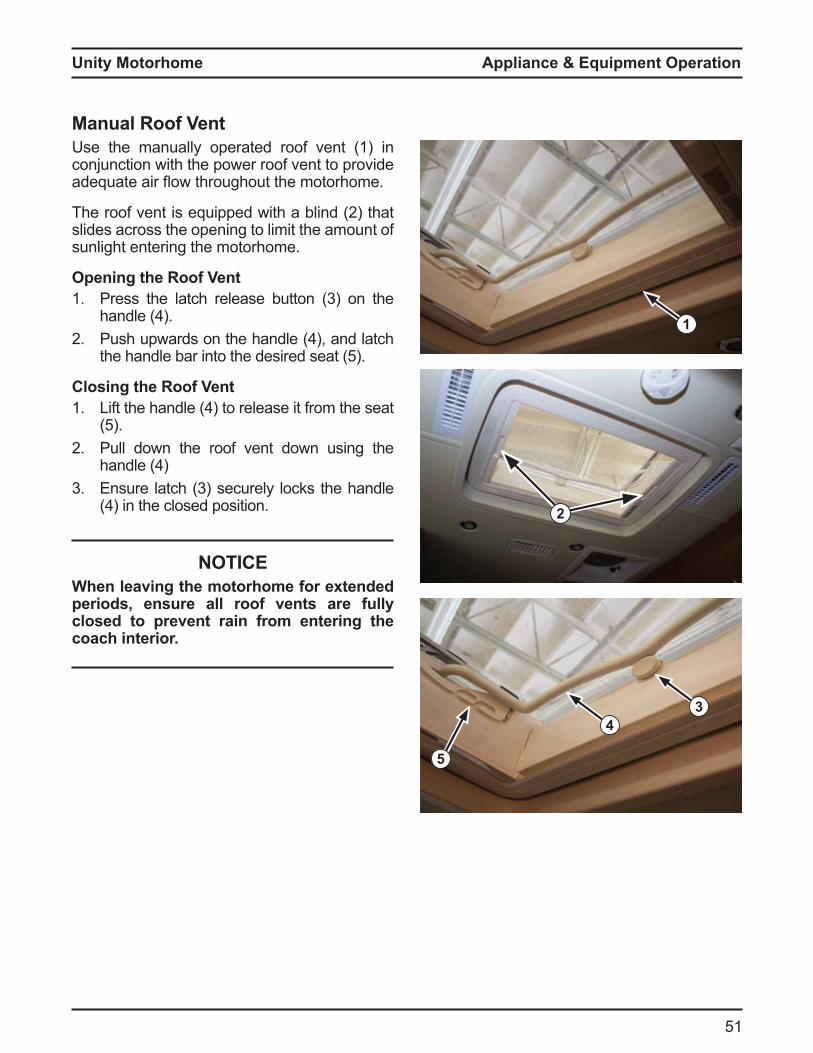
Unity Motorhome
51
Appliance & Equipment Operation
Manual Roof VentUse the manually operated roof vent (1) in conjunction with the power roof vent to provide ade uate air ow throughout the otorho e
The roo vent is e uipped with a lind 2 that slides across the opening to limit the amount of sunlight entering the motorhome.
Opening the Roof Vent1. Press the latch release utton 3 on the
handle 2 Push upwards on the handle , and latch
the handle ar into the desired seat 5
Closing the Roof Vent1. Li t the handle to release it ro the seat
52 Pull down the roof vent down using the
handle 3 nsure latch 3 securely locks the handle
in the closed position
NOTICEWhen leaving the motorhome for extended periods, ensure all roof vents are fully closed to prevent rain from entering the coach interior.
1
2
3
5
4
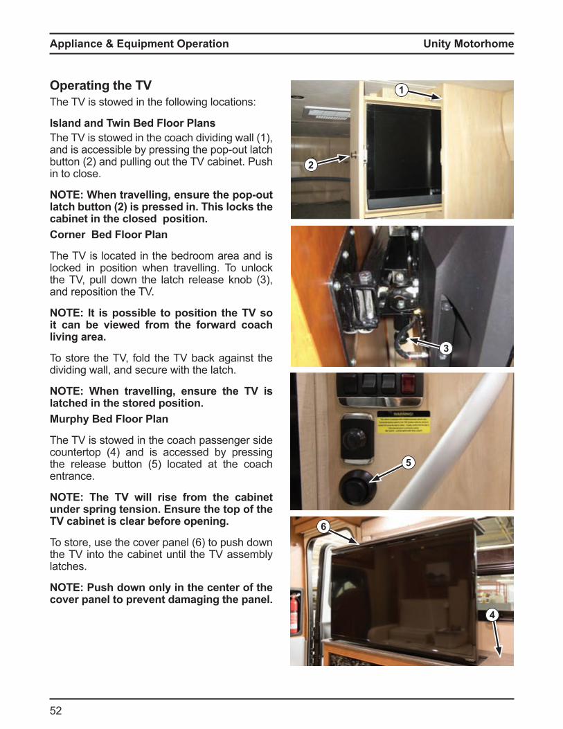
Unity Motorhome
52
Operating the TVThe TV is stowed in the following locations:
sland and win ed loor lansThe TV is stowed in the coach dividing wall (1), and is accessi le y pressing the pop out latch utton 2 and pulling out the T ca inet Push
in to close.
O When travelling ensure the pop out latch button 2 is pressed in. his loc s the cabinet in the closed position.Corner ed loor lan
The TV is located in the bedroom area and is locked in position when travelling. To unlock the T , pull down the latch release kno 3 , and reposition the TV.
O t is possible to position the V so it can be viewed from the forward coach living area.
To store the TV, fold the TV back against the dividing wall, and secure with the latch.
O When travelling ensure the V is latched in the stored position.
urph ed loor lan
The TV is stowed in the coach passenger side countertop and is accessed y pressing the release utton 5 located at the coach entrance.
O he V will rise from the cabinet under spring tension. Ensure the top of the
V cabinet is clear before opening.
To store, use the cover panel to push down the TV into the cabinet until the TV assembly latches.
O ush down onl in the center of the cover panel to prevent damaging the panel.
2
1
3
6
5
4
Appliance & Equipment Operation
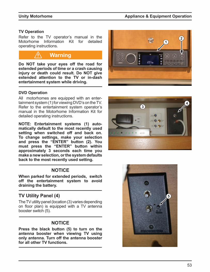
Unity Motorhome
53
Appliance & Equipment Operation
TV OperationRefer to the TV operator’s manual in the Motorhome Information Kit for detailed operating instructions.
Do NOT take your eyes off the road for extended periods of time or a crash causing injury or death could result. Do NOT give extended attention to the TV or in-dash entertainment system while driving.
DVD Operationll otorho es are e uipped with an enter
tainment system (1) for viewing DVD’s on the TV. Refer to the entertainment system operator’s manual in the Motorhome Information Kit for detailed operating instructions.
O ntertainment s stems 1 automatically default to the most recently used setting when switched off and bac on. To change settings, make your selection and press the button 2 . ou must press the button within approximately 3 seconds each time you make a new selection, or the system defaults bac to the most recentl used setting.
NOTICEWhen parked for extended periods, switch off the entertainment system to avoid draining the batter .
V tilit anel The T utility panel location 3 varies depending on oor plan is e uipped with a T antenna ooster switch 5
NOTICEress the blac button to turn on the
antenna booster when viewing V using onl antenna. urn off the antenna booster for all other TV functions.
12
5
Warning
43

Unity Motorhome
5
ternal Cable V ConnectionYour motorhome is equipped with an external cable TV hookup connector (1) located in the rear utility center.
O erform a channel scan on our V after connecting cable.
External Satellite TV ConnectionYour motorhome is equipped with an external satellite T hookup connector 2 located in the rear utility center.
TV AntennaYour motorhome is equipped with an o nidirectional antenna 3 ounted on the coach roof. The antenna is not adjustable.
HDMI Switch BoxYour motorhome may be equipped with an HDMI audio video switch o This ena les quality viewing for your DVD player or satellite receiver (not supplied).
Refer to the AV Wiring Diagrams section in this manual and the HDMI switch box manual in the Motorhome Information Kit for further details.
2
3
4
1
Appliance & Equipment Operation
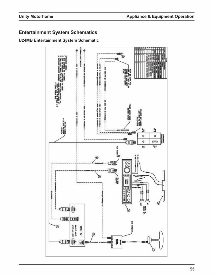
Unity Motorhome
55
Appliance & Equipment Operation
Entertainment System SchematicsU24MB Entertainment System Schematic
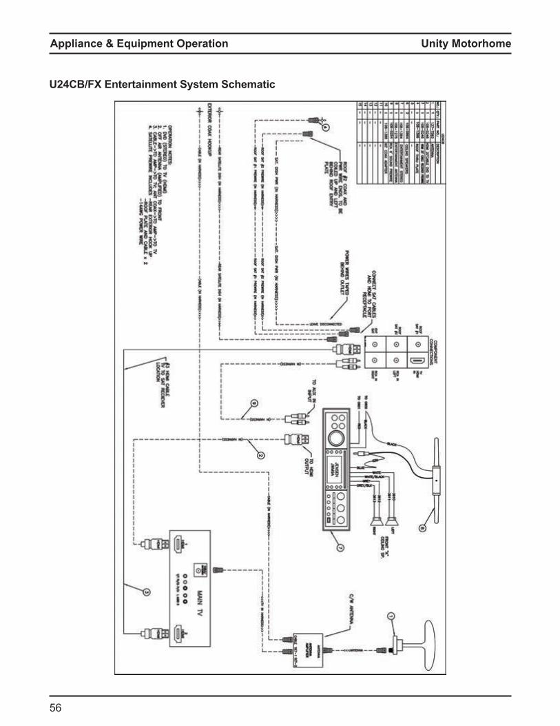
Unity Motorhome
5
U24CB/FX Entertainment System Schematic
Appliance & Equipment Operation
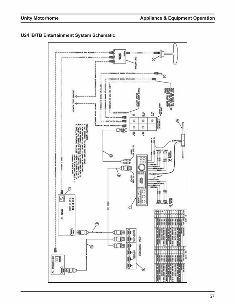
Unity Motorhome
57
Appliance & Equipment Operation
U24 IB/TB Entertainment System Schematic
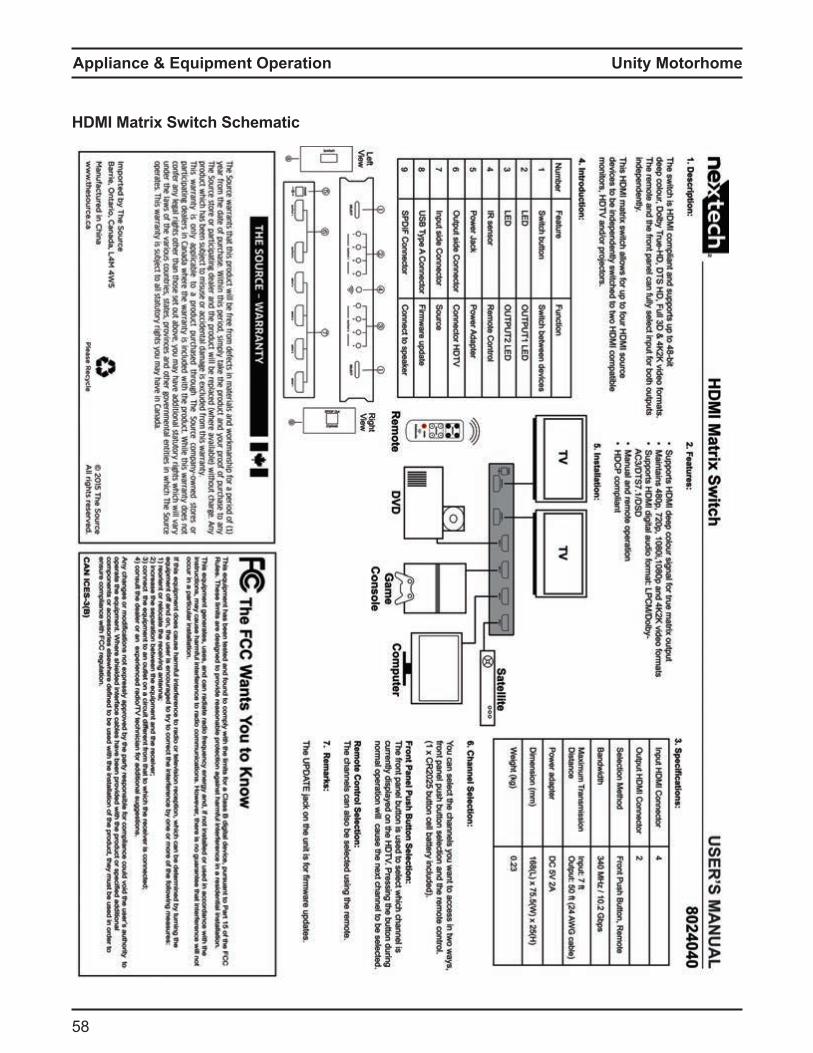
Unity Motorhome
58
HDMI Matrix Switch Schematic
Appliance & Equipment Operation
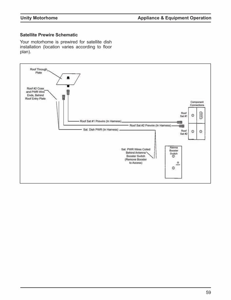
Unity Motorhome
59
Appliance & Equipment Operation
Satellite rewire SchematicYour motorhome is prewired for satellite dish installation location varies according to oor plan).
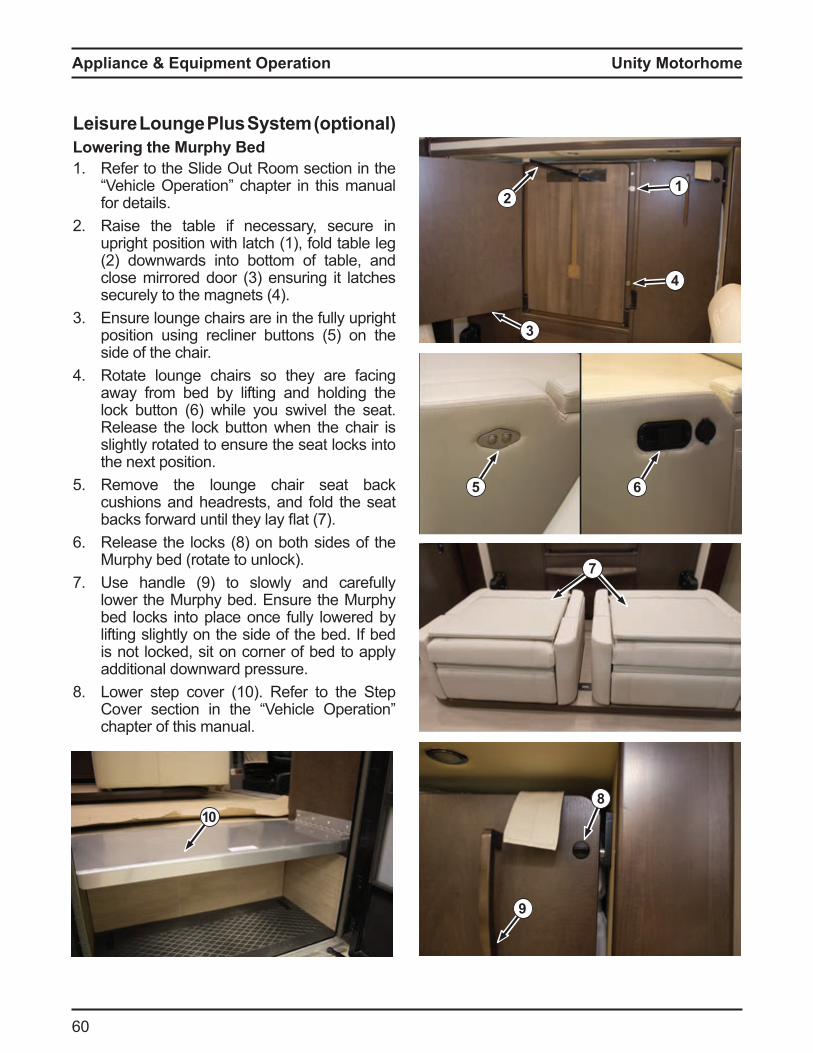
Unity Motorhome
0
Leisure Lounge lus S stem optionalLowering the urph ed1. Refer to the Slide Out Room section in the
ehicle peration chapter in this anual for details.
2 Raise the table if necessary, secure in upright position with latch (1), fold table leg 2 downwards into otto o ta le, and
close irrored door 3 ensuring it latches securely to the agnets
3 Ensure lounge chairs are in the fully upright position using recliner uttons 5 on the side of the chair.
Rotate lounge chairs so they are facing away from bed by lifting and holding the lock utton while you swivel the seat Release the lock button when the chair is slightly rotated to ensure the seat locks into the next position.
5 Remove the lounge chair seat back cushions and headrests, and fold the seat acks orward until they lay at 7
Release the locks (8) on both sides of the Murphy bed (rotate to unlock).
7. se handle 9 to slowly and care ully lower the Murphy bed. Ensure the Murphy bed locks into place once fully lowered by lifting slightly on the side of the bed. If bed is not locked, sit on corner of bed to apply additional downward pressure.
8. Lower step cover 10 Re er to the Step Cover section in the ehicle peration chapter of this manual.
12
3
4
5 6
7
8
9
10
Appliance & Equipment Operation
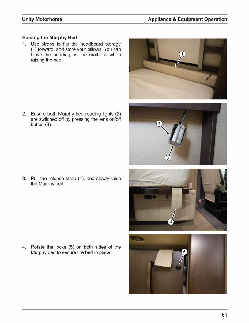
Unity Motorhome
1
Appliance & Equipment Operation
1
5
2
3
4
Raising the Murphy Bed1. se straps to ip the head oard storage
(1) forward, and store your pillows. You can leave the bedding on the mattress when raising the bed.
2 nsure oth urphy ed reading lights 2 are switched off by pressing the lens on/off utton 3
3 Pull the release strap , and slowly raise the Murphy bed.
Rotate the locks 5 on oth sides o the Murphy bed to secure the bed in place.
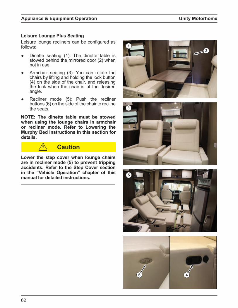
Unity Motorhome
62
2
Leisure Lounge Plus SeatingLeisure lounge recliners can e configured as follows:
inette seating 1 The dinette ta le is stowed ehind the irrored door 2 when not in use.
r chair seating 3 ou can rotate the chairs y li ting and holding the lock utton
on the side o the chair, and releasing the lock when the chair is at the desired angle.
Recliner ode 5 Push the recliner uttons on the side o the chair to recline
the seats.
NOTE: The dinette table must be stowed when using the lounge chairs in armchair or recliner mode. Refer to Lowering the Murphy Bed instructions in this section for details.
Lower the step cover when lounge chairs are in recliner mode (5) to prevent tripping accidents. Refer to the Step Cover section in the “Vehicle Operation” chapter of this manual for detailed instructions.
1
3
6 4
5
Caution
Appliance & Equipment Operation

Unity Motorhome
3
Appliance & Equipment Operation
Corner BedSeating/SleepingVaries ccording to loor lan
Booth Dinette Bed (1) Conversion1. Pull the ta le release handle 2 downwards,
and lower the table until it is level with the seating base.
2 Arrange the seat cushions as shown in igure 3
2
1
6
3
ooth inette ed Lounge Conversion1. Pull the ta le release handle 5 , and lower
the table until it is level with the seating base.2 Arrange the seat cushions as shown in
igure
5
5
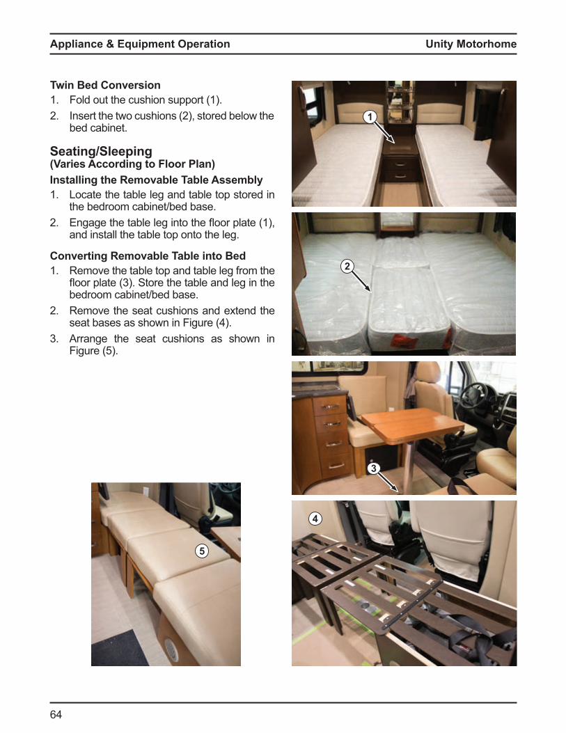
Unity Motorhome
Seating/SleepingVaries ccording to loor lannstalling the emovable able ssembl1. Locate the table leg and table top stored in
the bedroom cabinet/bed base.2 ngage the ta le leg into the oor plate 1 ,
and install the table top onto the leg.
Converting emovable able into ed1. Remove the table top and table leg from the
oor plate 3 Store the ta le and leg in the bedroom cabinet/bed base.
2 Remove the seat cushions and extend the seat ases as shown in igure
3 Arrange the seat cushions as shown in igure 5
3
Twin Bed Conversion1. Fold out the cushion support (1).2 nsert the two cushions 2 , stored elow the
bed cabinet.
2
5
1
4
Appliance & Equipment Operation
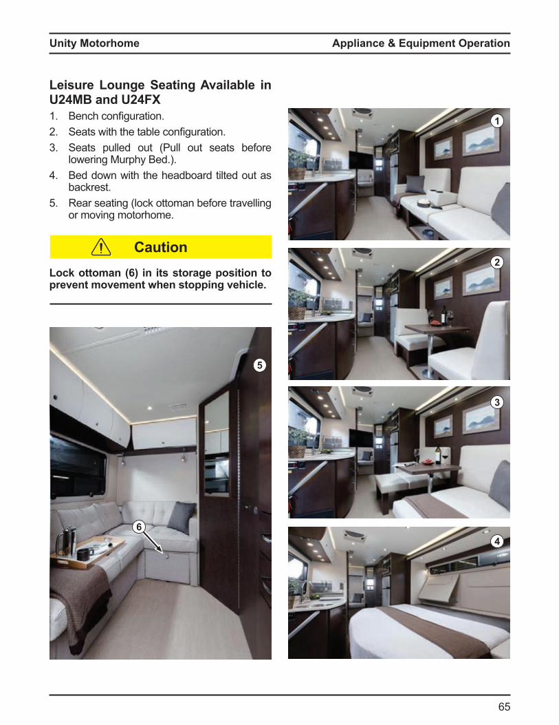
Unity Motorhome
65
Appliance & Equipment Operation
Leisure Lounge Seating Available in
U24MB and U24FX
1. ench configuration2. Seats with the ta le configuration3. Seats pulled out Pull out seats e ore
lowering urphy ed4. ed down with the head oard tilted out as
ackrest5. Rear seating lock otto an e ore travelling
or oving otorho e
Lock ottoman (6) in its storage position to
prevent movement when stopping vehicle.
1
2
3
4
5
Caution
6
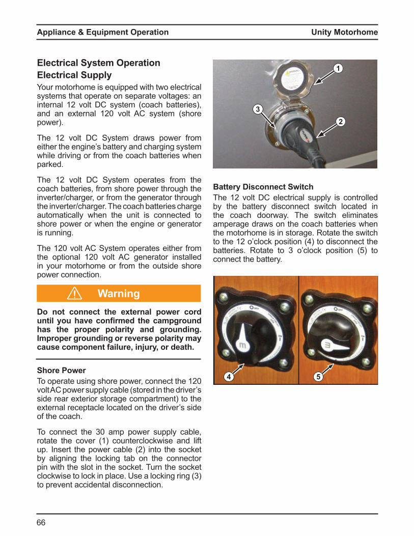
Unity Motorhome
66
Appliance & Equipment Operation
Battery Disconnect Switch
The 12 volt C electrical supply is controlled y the attery disconnect switch located in
the coach doorway The switch eli inates a perage draws on the coach atteries when the otorho e is in storage Rotate the switch to the 12 o clock position to disconnect the atteries Rotate to 3 o clock position 5 to
connect the attery
3
1
2
Electrical System Operation
Electrical Supply
our otorho e is e uipped with two electrical syste s that operate on separate voltages an internal 12 volt C syste coach atteries , and an e ternal 120 volt C syste shore power
The 12 volt C Syste draws power ro either the engine s attery and charging syste while driving or ro the coach atteries when parked
The 12 volt C Syste operates ro the coach atteries, ro shore power through the inverter charger, or ro the generator through the inverter charger The coach atteries charge auto atically when the unit is connected to shore power or when the engine or generator is running
The 120 volt C Syste operates either ro the optional 120 volt C generator installed in your otorho e or ro the outside shore power connection
Do not connect the external power cord
until ou have confirmed the campground has the proper polarity and grounding.
Improper grounding or reverse polarity may
cause component failure, injury, or death.
Shore Power
To operate using shore power, connect the 120 volt C power supply ca le stored in the driver s side rear e terior storage co part ent to the e ternal receptacle located on the driver s side o the coach
To connect the 30 a p power supply ca le, rotate the cover 1 counterclockwise and li t up nsert the power ca le 2 into the socket y aligning the locking ta on the connector
pin with the slot in the socket Turn the socket clockwise to lock in place se a locking ring 3 to prevent accidental disconnection
4 5
Warning
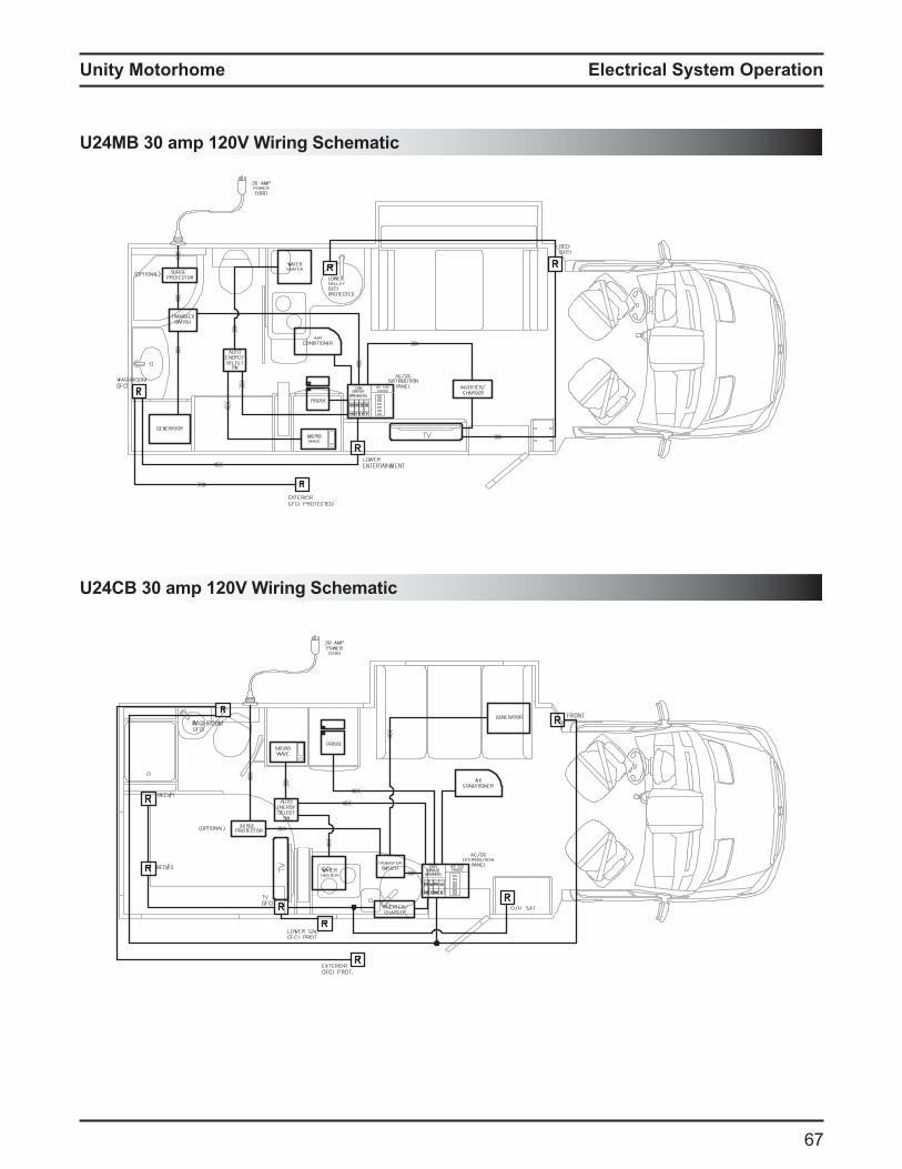
Unity Motorhome
7
U24MB 30 amp 120V Wiring Schematic
U24CB 30 amp 120V Wiring Schematic
Electrical System Operation
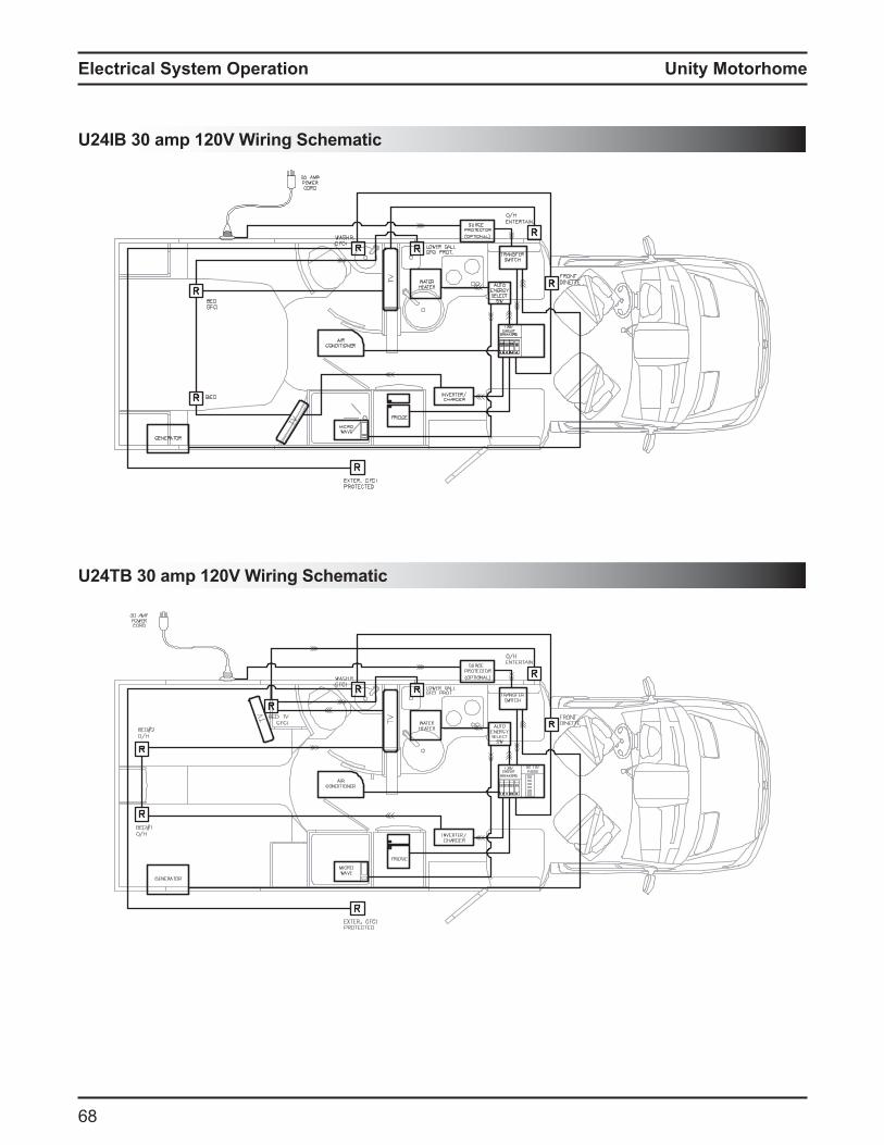
Unity Motorhome
8
Electrical System Operation
U24IB 30 amp 120V Wiring Schematic
U24TB 30 amp 120V Wiring Schematic
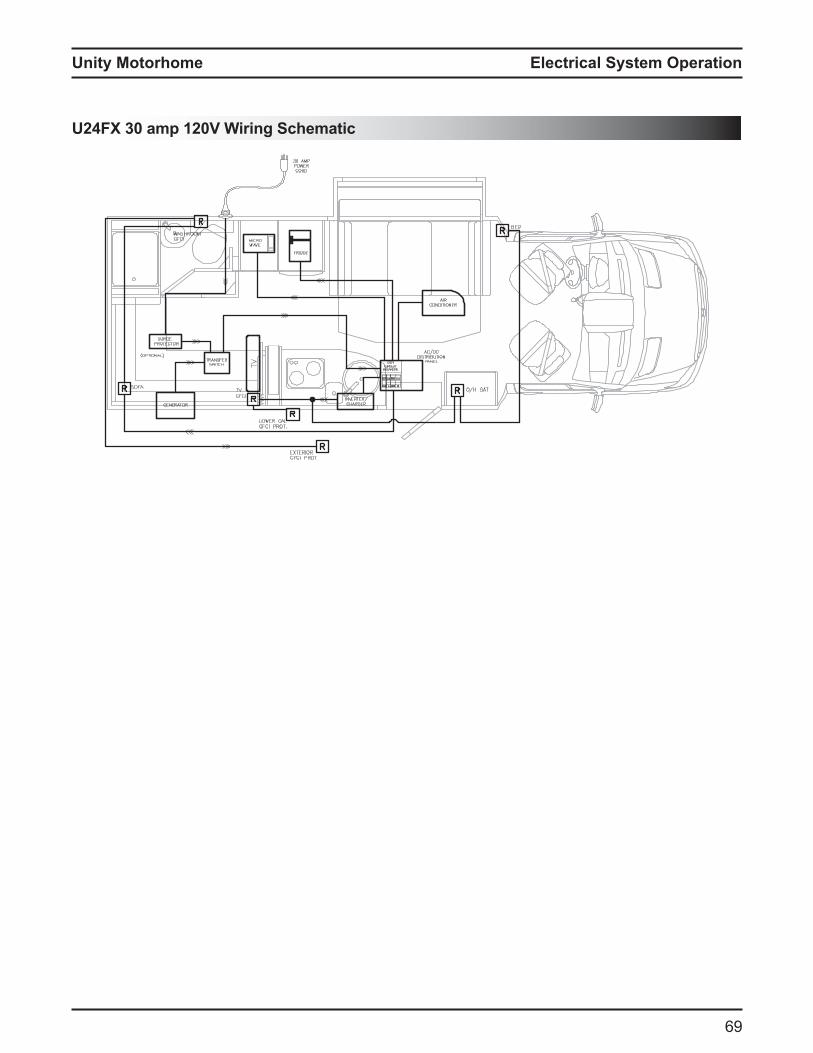
Unity Motorhome
9
U24FX 30 amp 120V Wiring Schematic
Electrical System Operation
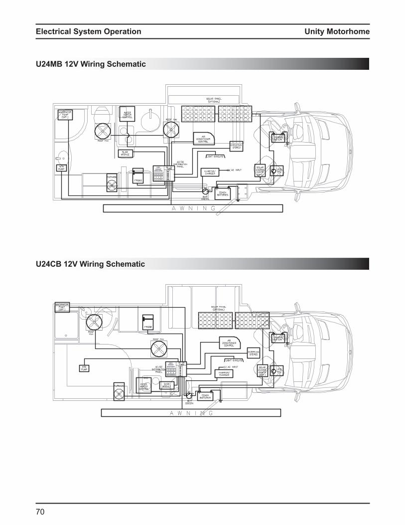
Unity Motorhome
70
Electrical System Operation
U24MB 12V Wiring Schematic
U24CB 12V Wiring Schematic
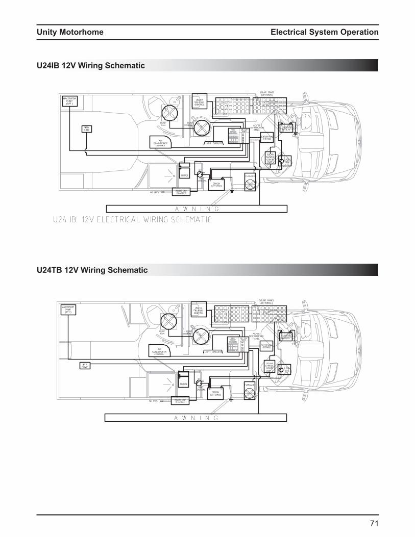
Unity Motorhome
71
U24IB 12V Wiring Schematic
U24TB 12V Wiring Schematic
Electrical System Operation

Unity Motorhome
72
Electrical System Operation
U24FX 12V Wiring Schematic
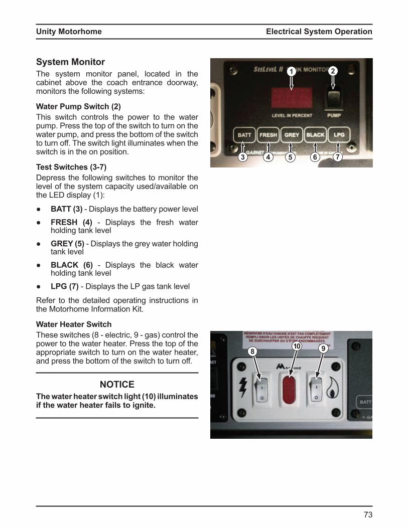
Unity Motorhome
73
System MonitorThe system monitor panel, located in the cabinet above the coach entrance doorway, monitors the following systems:
Water ump Switch 2This switch controls the power to the water pump. Press the top of the switch to turn on the water pump, and press the bottom of the switch to turn off. The switch light illuminates when the switch is in the on position.
Test Switches (3-7)Depress the following switches to monitor the level of the system capacity used/available on the LED display (1):
BATT (3) isplays the attery power level FRESH (4) isplays the resh water
holding tank level GREY (5) isplays the grey water holding
tank level L C isplays the lack water
holding tank level L isplays the LP gas tank level
Refer to the detailed operating instructions in the Motorhome Information Kit.
Water Heater SwitchThese switches 8 electric, 9 gas control the power to the water heater. Press the top of the appropriate switch to turn on the water heater, and press the bottom of the switch to turn off.
NOTICEThe water heater switch light (10) illuminates if the water heater fails to ignite.
3 4 5 6 7
1 2
8 910
Electrical System Operation
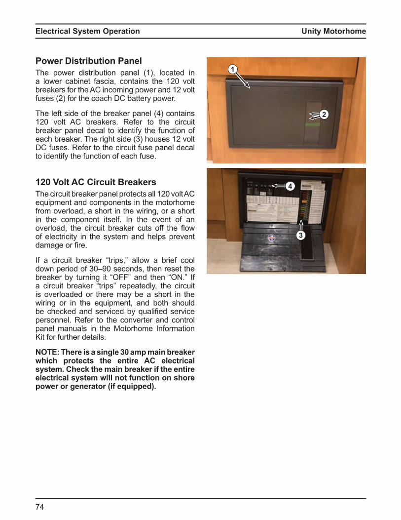
Unity Motorhome
7
Electrical System Operation
ower istribution anelThe power distribution panel (1), located in a lower ca inet ascia, contains the 120 volt reakers or the C inco ing power and 12 volt
uses 2 or the coach C attery power
The le t side o the reaker panel contains 120 volt C reakers Re er to the circuit breaker panel decal to identify the function of each reaker The right side 3 houses 12 volt DC fuses. Refer to the circuit fuse panel decal to identify the function of each fuse.
120 Volt AC Circuit BreakersThe circuit reaker panel protects all 120 volt C equipment and components in the motorhome from overload, a short in the wiring, or a short in the component itself. In the event of an overload, the circuit reaker cuts o the ow of electricity in the system and helps prevent da age or fire
a circuit reaker trips, allow a rie cool down period o 30 90 seconds, then reset the reaker y turning it and then
a circuit reaker trips repeatedly, the circuit is overloaded or there may be a short in the wiring or in the equipment, and both should e checked and serviced y ualified service
personnel. Refer to the converter and control panel manuals in the Motorhome Information Kit for further details.
O here is a single 3 amp main brea er which protects the entire AC electrical s stem. Chec the main brea er if the entire electrical system will not function on shore power or generator (if equipped).
1
2
4
3
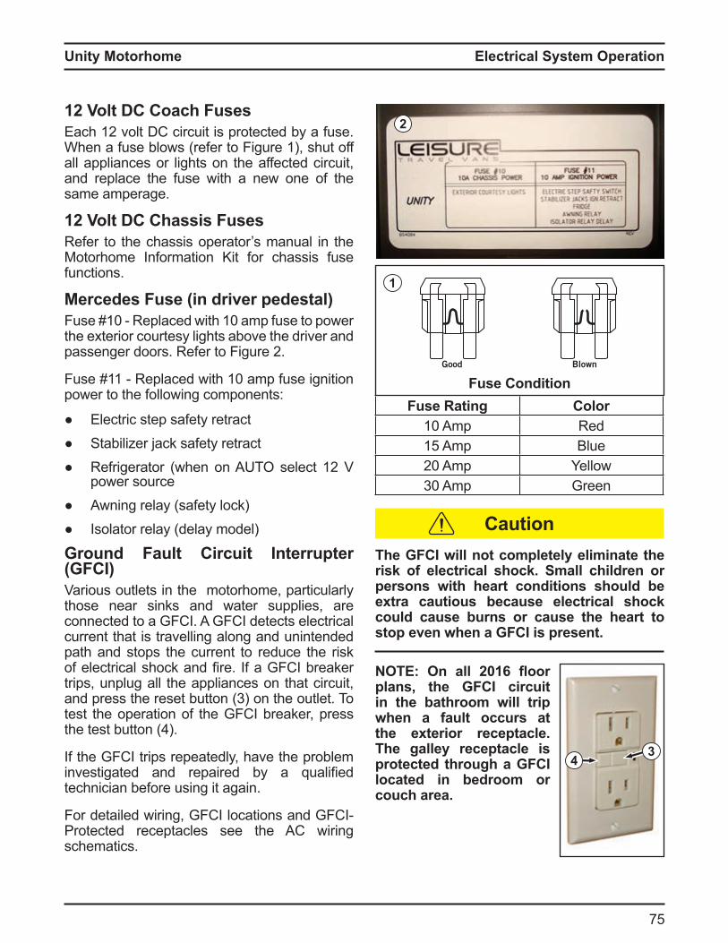
Unity Motorhome
75
12 Volt DC Coach Fusesach 12 volt C circuit is protected y a use
When a fuse blows (refer to Figure 1), shut off all appliances or lights on the affected circuit, and replace the fuse with a new one of the same amperage.
12 Volt DC Chassis FusesRefer to the chassis operator’s manual in the Motorhome Information Kit for chassis fuse functions.
Mercedes Fuse (in driver pedestal)use 10 Replaced with 10 a p use to power
the exterior courtesy lights above the driver and passenger doors Re er to igure 2
use 11 Replaced with 10 a p use ignition power to the following components:
Electric step safety retract Stabilizer jack safety retract Re rigerator when on T select 12
power source Awning relay (safety lock) Isolator relay (delay model)
Ground Fault Circuit Interrupter (GFCI)Various outlets in the motorhome, particularly those near sinks and water supplies, are connected to a GFCI. A GFCI detects electrical current that is travelling along and unintended path and stops the current to reduce the risk o electrical shock and fire a G C reaker trips, unplug all the appliances on that circuit, and press the reset utton 3 on the outlet To test the operation of the GFCI breaker, press the test utton
If the GFCI trips repeatedly, have the problem investigated and repaired y a ualified technician before using it again.
or detailed wiring, G C locations and G CProtected receptacles see the AC wiring schematics.
Fuse ConditionFuse Rating Color
10 p Red15 p Blue20 p Yellow30 p Green
1
2
The GFCI will not completely eliminate the risk of electrical shock. Small children or persons with heart conditions should be e tra cautious because electrical shoc could cause burns or cause the heart to stop even when a GFCI is present.
O On all 2 1 oor plans, the GFCI circuit in the bathroom will trip when a fault occurs at the exterior receptacle. The galley receptacle is protected through a GFCI located in bedroom or couch area.
43
Caution
Good BlownGood Blown
Electrical System Operation
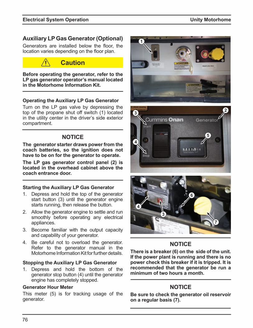
Unity Motorhome
7
Electrical System Operation
u iliar L as enerator OptionalGenerators are installed elow the oor, the location varies depending on the oor plan
Before operating the generator, refer to the L gas generator operator s manual located in the Motorhome Information Kit.
Operating the u iliar L as eneratorTurn on the LP gas valve by depressing the top of the propane shut off switch (1) located in the utility center in the driver’s side exterior compartment.
NOTICEThe generator starter draws power from the coach batteries so the ignition does not have to be on for the generator to operate.
he L gas generator control panel 2 is located in the overhead cabinet above the coach entrance door.
Starting the u iliar L as enerator 1. Depress and hold the top of the generator
start utton 3 until the generator engine starts running, then release the button.
2 Allow the generator engine to settle and run smoothly before operating any electrical appliances.
3 Become familiar with the output capacity and capability of your generator.
Be careful not to overload the generator. Refer to the generator manual in the Motorhome Information Kit for further details.
Stopping the u iliar L as enerator1. Depress and hold the bottom of the
generator stop utton until the generator engine has completely stopped.
Generator Hour MeterThis eter 5 is or tracking usage o the generator.
23
4
Caution
1
5
NOTICEhere is a brea er on the side of the unit.
If the power plant is running and there is no power chec this brea er if it is tripped. t is recommended that the generator be run a minimum of two hours a month.
NOTICEBe sure to check the generator oil reservoir on a regular basis .
6
43
7
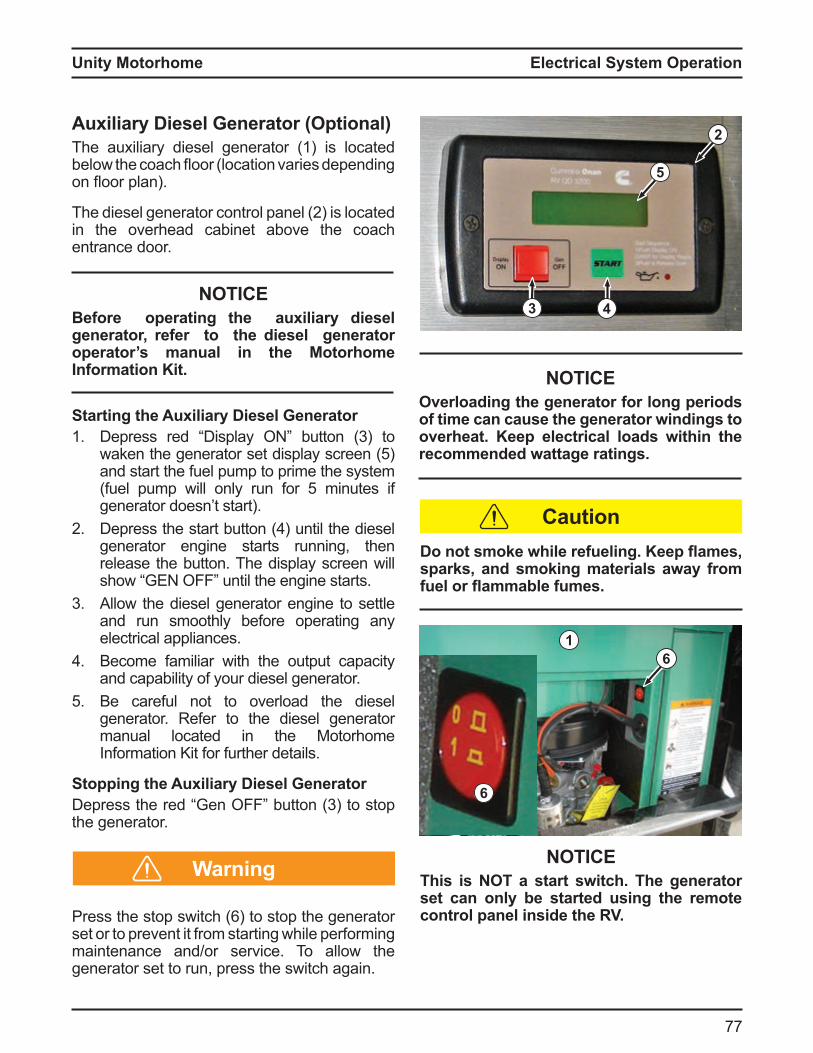
Unity Motorhome
77
Auxiliary Diesel Generator (Optional)The auxiliary diesel generator (1) is located elow the coach oor location varies depending
on oor plan
The diesel generator control panel 2 is located in the overhead cabinet above the coach entrance door.
NOTICEBefore operating the auxiliary diesel generator, refer to the diesel generator operator’s manual in the Motorhome Information Kit.
Starting the Auxiliary Diesel Generator1. epress red isplay utton 3 to
waken the generator set display screen 5 and start the fuel pump to prime the system
uel pu p will only run or 5 inutes i generator doesn’t start).
2 epress the start utton until the diesel generator engine starts running, then release the button. The display screen will show G until the engine starts
3 Allow the diesel generator engine to settle and run smoothly before operating any electrical appliances.
Become familiar with the output capacity and capability of your diesel generator.
5 Be careful not to overload the diesel generator. Refer to the diesel generator manual located in the Motorhome Information Kit for further details.
Stopping the Auxiliary Diesel Generatorepress the red Gen utton 3 to stop
the generator.
Press the stop switch to stop the generator set or to prevent it from starting while performing maintenance and/or service. To allow the generator set to run, press the switch again.
2
3 4
o not smo e while refueling. eep ames sparks, and smoking materials away from fuel or ammable fumes.
Caution
NOTICEOverloading the generator for long periods of time can cause the generator windings to overheat. Keep electrical loads within the recommended wattage ratings.
5
16
6
NOTICEThis is NOT a start switch. The generator set can onl be started using the remote control panel inside the RV.
Warning
Electrical System Operation

Unity Motorhome
78
Electrical System Operation
Generator SafetyElectrical
Exercise extreme care and caution when handling the generator and its components. Carelessness can be dangerous and even fatal.Never touch any electrical leads, equipment, or appliances when your hands are wet or when you are standing on wet ground or in water.Do NOT attempt to repair the generator yourself. Have all service and repairs performed at an authorized service center only.Never check the generator oil level while the generator engine is running.
Asphyxiation
ll internal combustion engines produce carbon mono ide CO gas fumes when running. This gas is poisonous , colorless, odorless, tasteless, and is lighter than air.
1. Do not run the generator and an intake vent fan at the same time. This could draw gases into the motorhome.
2 Do not open windows or vents on the side where the generator exhaust pipes are located.
3 Park so the wind carries exhaust gases away from the motorhome. Be aware of potential gas fumes from other nearby vehicles.
Do not operate the generator if there are any obstructions such as vegetation, snow, uildings, etc , which could de ect gas
fumes under or into the motorhome.
utomatic ower ransfer SwitchAutomatic Switch OverStart the generator to automatically switch over ro 120 volt C shore power to generator power.
Built-in Delay 20 30 second delay prevents the generator
from starting while under load. This delay allows the generator to have the required amount of war up ti e e ore trans erring power
This switch automatically transfers power when switching etween 120 volt shore power and generator power, and prevents damage to any circuitry if the shore power and generator are inadvertently operated simultaneously.
NOTICEAlways verify that appliances are turned off before starting or stopping the generator. Do NOT start the generator while it is under load. Ensuring all appliances are in the off position will help prolong the life of these systems.
Warning
Warning
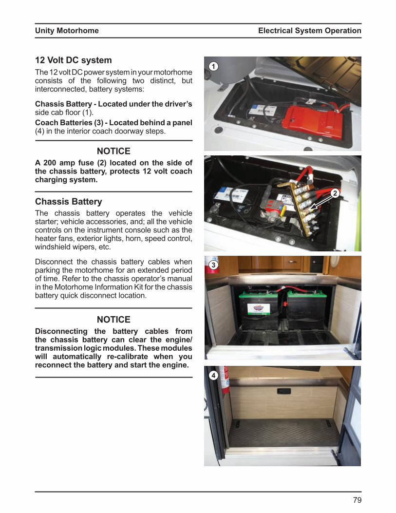
Unity Motorhome
79
12 Volt DC systemThe 12 volt C power syste in your otorho e consists of the following two distinct, but interconnected, battery systems:
Chassis atter Located under the driver s side ca oor 1Coach atteries 3 Located behind a panel
in the interior coach doorway steps
NOTICEA 200 amp fuse (2) located on the side of the chassis batter protects 12 volt coach charging system.
Chassis BatteryThe chassis battery operates the vehicle starter; vehicle accessories, and; all the vehicle controls on the instrument console such as the heater fans, exterior lights, horn, speed control, windshield wipers, etc.
Disconnect the chassis battery cables when parking the motorhome for an extended period of time. Refer to the chassis operator’s manual in the Motorhome Information Kit for the chassis battery quick disconnect location.
NOTICEisconnecting the batter cables from
the chassis batter can clear the enginetransmission logic modules. These modules will automaticall re calibrate when ou reconnect the batter and start the engine.
3
4
2
1
Electrical System Operation
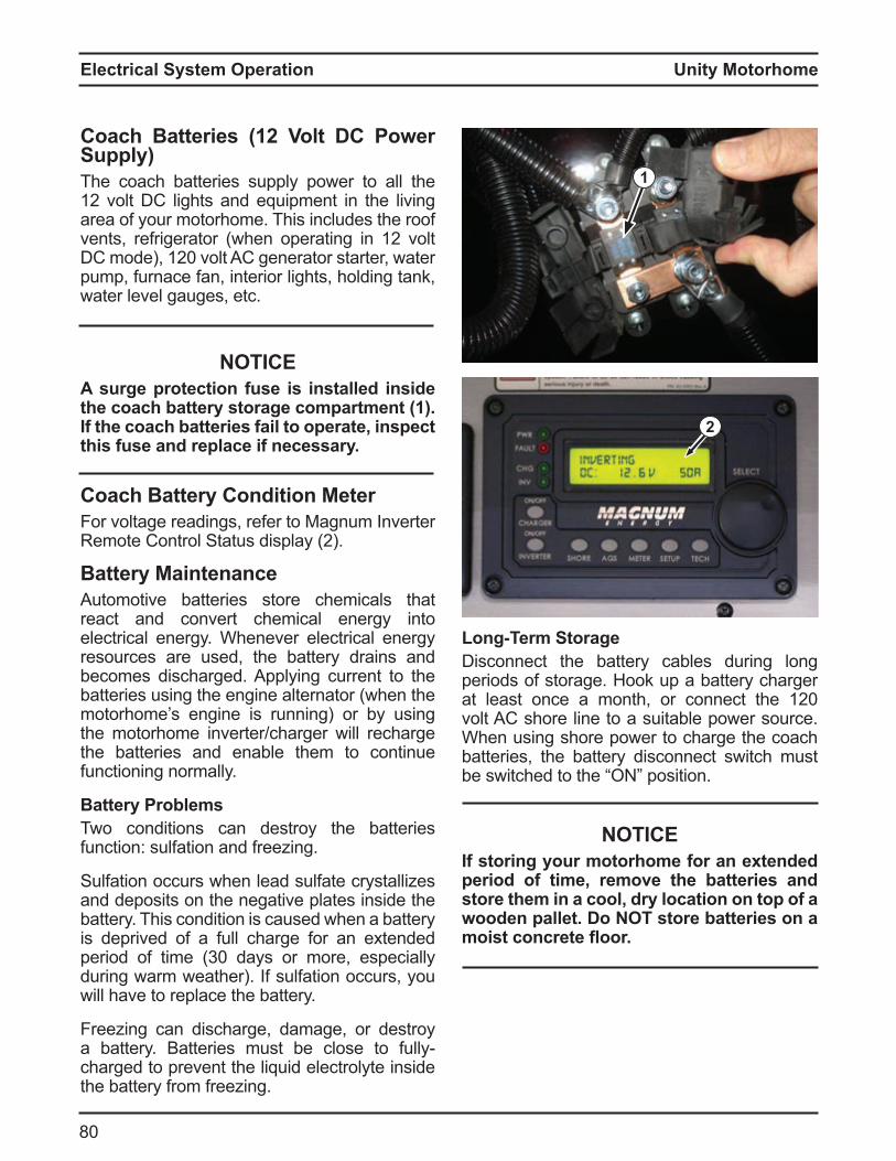
Unity Motorhome
80
Electrical System Operation
Coach atteries 12 Volt C ower Supply)The coach batteries supply power to all the 12 volt C lights and e uip ent in the living area of your motorhome. This includes the roof vents, re rigerator when operating in 12 volt
C ode , 120 volt C generator starter, water pump, furnace fan, interior lights, holding tank, water level gauges, etc.
NOTICEA surge protection fuse is installed inside the coach batter storage compartment 1 . f the coach batteries fail to operate inspect this fuse and replace if necessary.
Coach Battery Condition MeterFor voltage readings, refer to Magnum Inverter Re ote Control Status display 2
Battery MaintenanceAutomotive batteries store chemicals that react and convert chemical energy into electrical energy. Whenever electrical energy resources are used, the battery drains and becomes discharged. Applying current to the batteries using the engine alternator (when the motorhome’s engine is running) or by using the motorhome inverter/charger will recharge the batteries and enable them to continue functioning normally.
atter roblemsTwo conditions can destroy the batteries function: sulfation and freezing.
Sulfation occurs when lead sulfate crystallizes and deposits on the negative plates inside the battery. This condition is caused when a battery is deprived of a full charge for an extended period o ti e 30 days or ore, especially during warm weather). If sulfation occurs, you will have to replace the battery.
Freezing can discharge, damage, or destroy a attery atteries ust e close to ullycharged to prevent the liquid electrolyte inside the battery from freezing.
2
Long erm StorageDisconnect the battery cables during long periods of storage. Hook up a battery charger at least once a onth, or connect the 120 volt AC shore line to a suitable power source. When using shore power to charge the coach batteries, the battery disconnect switch must e switched to the position
NOTICEIf storing your motorhome for an extended period of time remove the batteries and store them in a cool, dry location on top of a wooden pallet. o O store batteries on a moist concrete oor.
1

Unity Motorhome
81
Additional Battery Maintenance Suggestions1. Perform monthly inspections of the batteries’
external condition. Look for cracks in the covers and cases.
2 Ensure batteries are securely fastened in the proper position.
3 Make sure battery clamps are tight and free from corrosion.
Keep the batteries and terminals clean. Acid and dirt accu ulation can prevent su ficient current ro owing through the ca les, and can per it current to ow etween the terminals causing the batteries to discharge.
o not allow batter electrol te to contact s in e es fabrics or painted surfaces. The electrolyte is a sulfuric acid solution which could cause serious personal injury or property damage. Wear eye protection when wor ing around batteries.
5 Clean the battery with a solution of baking soda and water to neutralize any acid present, then ush with clean water oa ing around terminals or on top of the battery is normal during the cleaning process.
NOTICEo O allow an ba ing soda solution to
get into the batter . his can neutralize the batter acid.
Dry the cables and terminals before reinstalling them. Do NOT apply grease to the metal surfaces inside the cable terminals to prevent corrosion. Grease is an insulator and will prevent the ow o electricity se a plastic ignition spray to protect the terminals after you have cleaned and reinstalled them.
Warning
Caution
O When removing replacing boosting or charging the batteries ensure the red positive cable terminals are connected to the positive
posts and the blac negative cable terminals are connected to the negative (-) posts.
7. If installing batteries or booster/charger cables, attach the red positive (+) cable ter inals first, then attach the lack negative
ca le ter inals8. If removing batteries or booster/charger
ca les, re ove the lack negative ca le ter inals first, then re ove the red positive (+) cable terminals.
9 Do NOT attempt to recharge frozen batteries.10 using a attery uick charge unit,
disconnect the cables from the batteries.
NOTICEDo NOT attempt to start the engine using a batter uic charge unit.
11. you do not have aintenance ree atteries, check the attery uid level and
fill with distilled water i necessary o not overfill
12 ave the specific gravity o the attery uid checked during regular motorhome service and maintenance.
emove rings metal watchbands and other metal ewelr before wor ing around a batter . se caution when using metal tools. f the tool contacts the batter terminals or the metal connected to them, a short circuit could result.
Electrical System Operation

Unity Motorhome
82
Electrical System Operation
Olease be aware that inverters use a standb
current drain even when your equipment is turned off so to ensure our batter life turn off the inverter function when not in use.
NOTICEThe inverter is not intended for appliances that consume more than the specified inverter wattage. ceeding the specified wattage could result in damage to the appliance or the inverter. Extended use of the inverter-powered receptacles will drain our batteries.
Before performing any service, insure the inverter is completely disconnected from power sources. isconnect batter 12V C and shore power (120V AC). Inverter should onl be services b a ualified technician.
InverterTriple E RV/Leisure Travel Vans uses Magnum 1200W nverter Charges The 1200W inverters are standard on all units. Inverters operate on the ollowing principal they change 12 C power stored in atteries into 120 C power used in household appliances The 1200W inverter can supply 10 C at ull capacity it has a 15 output reaker 2 and a 20 input reaker 1 The 15 reaker powers the Bedroom, Entertainment and Galley receptacle. When the motor home is plugged into shore power, the breaker panel supplies power to the inverter, which switches that power through to the ‘inverter loads’.
When shore power or generator power is absent, the inverter can be switched on and used to supply 120 volt power to the loads mentioned above, no other receptacles will have power The 1200 watt inverter has an internal attery charger set to 55 a ps nce the inverter has accepted the AC input power, Charge Mode will begin, however it is possible to turn the charger function off.
The Magnum Monitor instrument is a complex computer control and monitor device, it is used on all nits t is actory configured or the particular inverter and battery installation Triple E RV/Leisure Travel Vans uses. If any
odifications are ever ade to the attery bank, it may be necessary to change some internal parameters. Please refer to the Inverter / Remote Control manual for setting or contact the anu acturer The agnu RC50 controls the invert and charge features of the Inverter.
NOTICEhe invert feature needs to be manuall
switched ‘on’ and ‘off’, however when the inverter Feature was turned ON and the batter disconnect switch has been turned off ne t time the nverter has been powered up the inverter feature needs to be turned on manually.
2
1
Caution
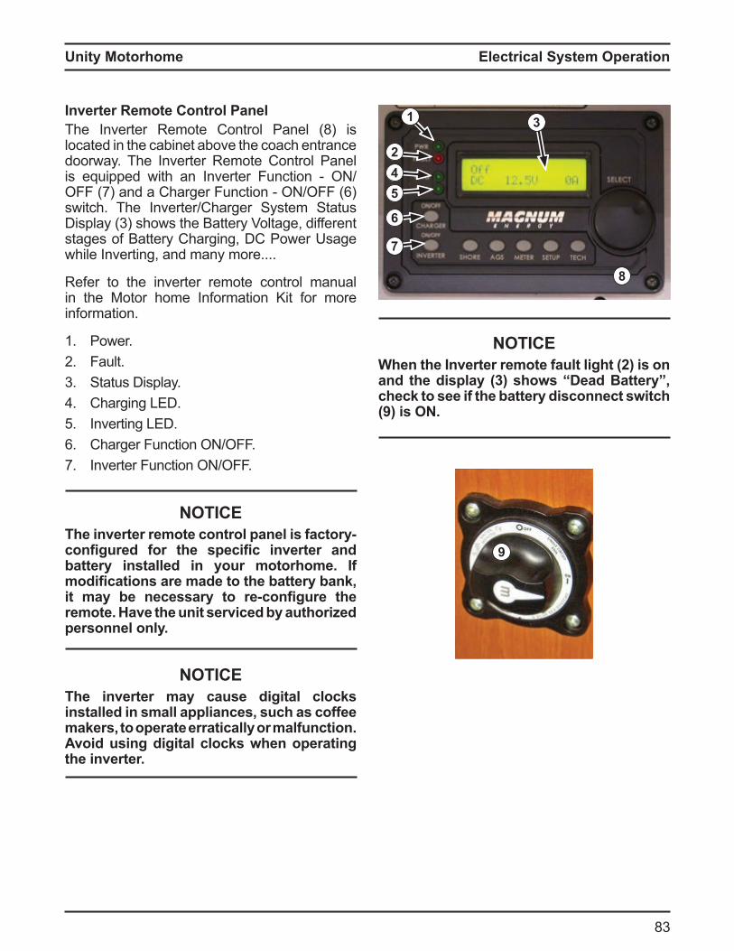
Unity Motorhome
83
nverter emote Control anelThe Inverter Remote Control Panel (8) is located in the cabinet above the coach entrance doorway. The Inverter Remote Control Panel is e uipped with an nverter unction
7 and a Charger unction switch. The Inverter/Charger System Status
isplay 3 shows the attery oltage, di erent stages of Battery Charging, DC Power Usage while Inverting, and many more....
Refer to the inverter remote control manual in the Motor home Information Kit for more information.
1. Power.2 Fault.3 Status Display.
Charging LED.5 Inverting LED.
Charger Function ON/OFF.7. Inverter Function ON/OFF.
NOTICEThe inverter remote control panel is factory-configured for the specific inverter and batter installed in our motorhome. f modifications are made to the batter ban it ma be necessar to re configure the remote. ave the unit serviced b authorized personnel only.
NOTICEThe inverter may cause digital clocks installed in small appliances, such as coffee makers, to operate erratically or malfunction. Avoid using digital clocks when operating the inverter.
1 3
24
6
7
5
8
NOTICEWhen the Inverter remote fault light (2) is on and the displa 3 shows ead atter chec to see if the batter disconnect switch (9) is ON.
9
Electrical System Operation
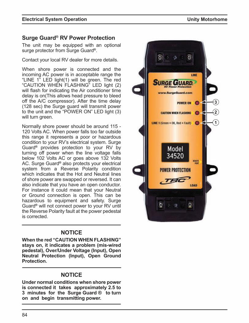
Unity Motorhome
8
Electrical System Operation
Surge Guard® V ower rotectionThe unit may be equipped with an optional surge protector from Surge Guard®.
Contact your local RV dealer for more details.
When shore power is connected and the incoming AC power is in acceptable range the L 1 L light 1 will e green The red C T W L S G L light 2
will ash or indicating the ir conditioner ti e delay is on(This allows head pressure to bleed off the A/C compressor). After the time delay 128 sec the Surge guard will trans it power
to the unit and the P W R L light 3 will turn green.
or ally shore power should e around 115 120 olts C When power alls too ar outside this range it represents a poor or hazardous condition to your RV’s electrical system. Surge Guard® provides protection to your RV by turning off power when the line voltage falls elow 102 olts C or goes a ove 132 olts
AC. Surge Guard® also protects your electrical system from a Reverse Polarity condition which indicates that the Hot and Neutral lines of shore power are swapped or reversed. It can also indicate that you have an open conductor. For instance it could mean that your Neutral or Ground connection is open. This can be hazardous to equipment and safety. Surge Guard® will not connect power to your RV until the Reverse Polarity fault at the power pedestal is corrected.
NOTICEWhen the red C O W L S sta s on it indicates a problem mis wired pedestal), Over/Under Voltage (Input), Open
eutral rotection nput Open round rotection.
NOTICEUnder normal conditions when shore power is connected it takes approximately 2.5 to 3 minutes for the Surge Guard ® to turn on and begin transmitting power.
2
3
1
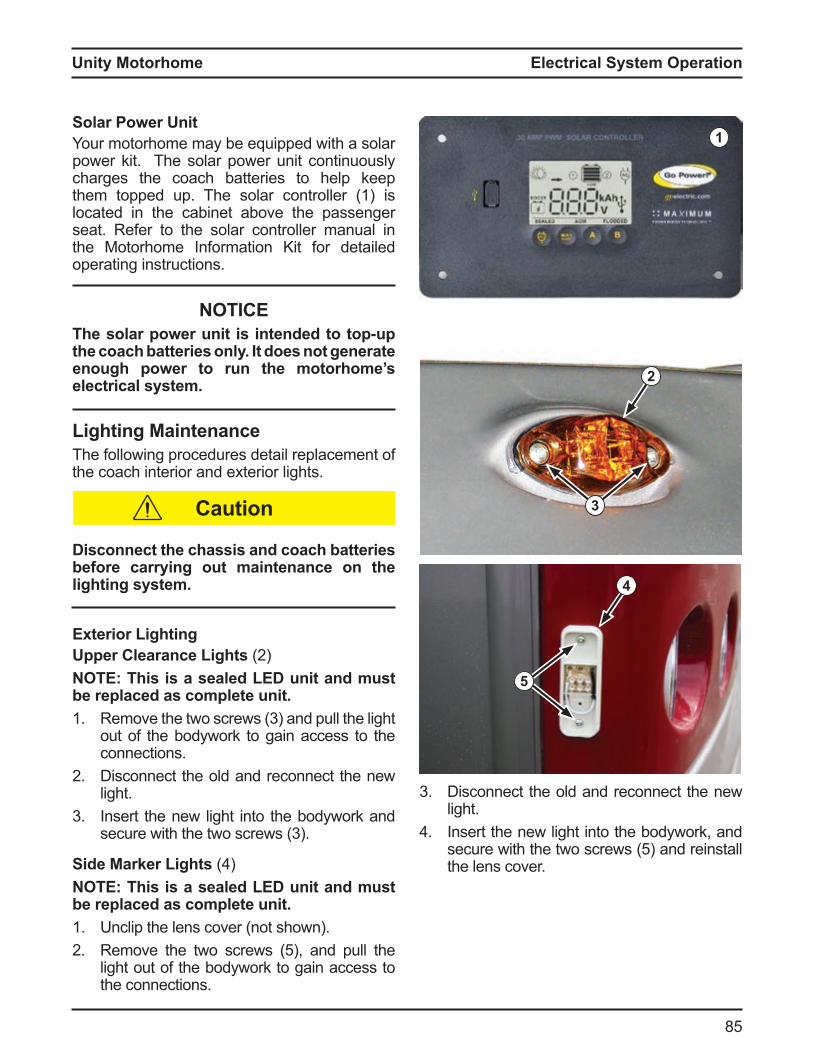
Unity Motorhome
85
Electrical System Operation
2
3
4
5
Solar ower nitYour motorhome may be equipped with a solar power kit. The solar power unit continuously charges the coach batteries to help keep them topped up. The solar controller (1) is located in the cabinet above the passenger seat. Refer to the solar controller manual in the Motorhome Information Kit for detailed operating instructions.
NOTICEThe solar power unit is intended to top-up the coach batteries onl . t does not generate enough power to run the motorhome’s electrical system.
Lighting aintenanceThe following procedures detail replacement of the coach interior and exterior lights.
isconnect the chassis and coach batteries before carr ing out maintenance on the lighting system.
terior Lightingpper Clearance Lights 2O his is a sealed L unit and must
be replaced as complete unit.1. Re ove the two screws 3 and pull the light
out of the bodywork to gain access to the connections.
2 Disconnect the old and reconnect the new light.
3 Insert the new light into the bodywork and secure with the two screws 3
Side ar er Lights O his is a sealed L unit and must
be replaced as complete unit.1. Unclip the lens cover (not shown).2 Re ove the two screws 5 , and pull the
light out of the bodywork to gain access to the connections.
1
Caution
3 Disconnect the old and reconnect the new light.
Insert the new light into the bodywork, and secure with the two screws 5 and reinstall the lens cover.
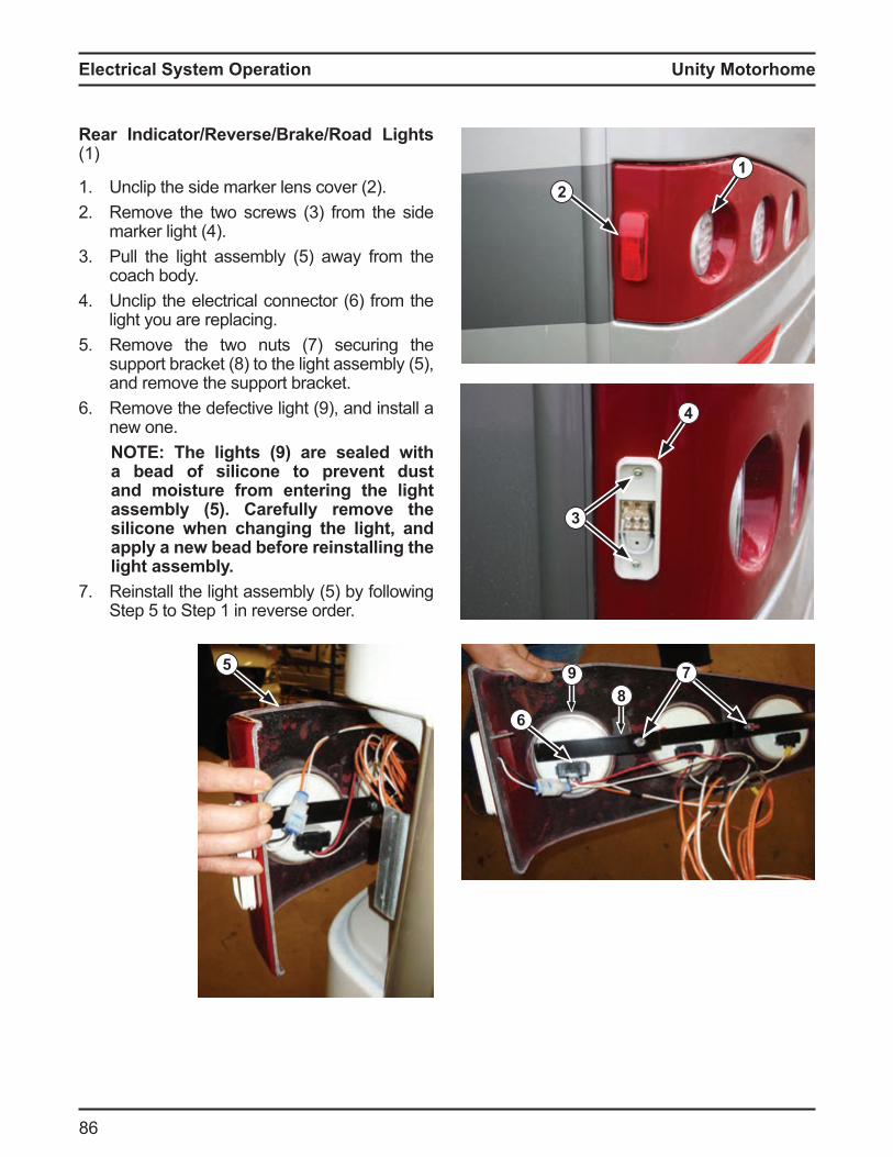
Unity Motorhome
8
4
3
ear ndicator everse ra e oad Lights (1)
1. nclip the side arker lens cover 22 Re ove the two screws 3 ro the side
arker light 3 Pull the light asse ly 5 away ro the
coach body. nclip the electrical connector ro the
light you are replacing.5 Remove the two nuts (7) securing the
support racket 8 to the light asse ly 5 , and remove the support bracket.
Re ove the de ective light 9 , and install a new one.
O he lights are sealed with a bead of silicone to prevent dust and moisture from entering the light assembl . Carefull remove the silicone when changing the light, and appl a new bead before reinstalling the light assembl .
7. Reinstall the light asse ly 5 y ollowing Step 5 to Step 1 in reverse order
12
5
6
78
9
Electrical System Operation

Unity Motorhome
87
Electrical System Operation
3
4
terior lood Light (1)
1. nclip plastic cover 22 Remove and replace light.3 Install cover.
2
1
nterior LightingCabin Lights 3
O his is a sealed L unit and must be replaced as complete unit. 1. Pull down on the light fitting 32 Install a new light into the opening.
eading Lights The coach reading lights are not serviceable. If the reading light stops working, have the entire unit replaced y a ualified service technician
NOTICEll L lights are not serviceable. f an
light stops working, have the entire light replaced b a ualified service technician.
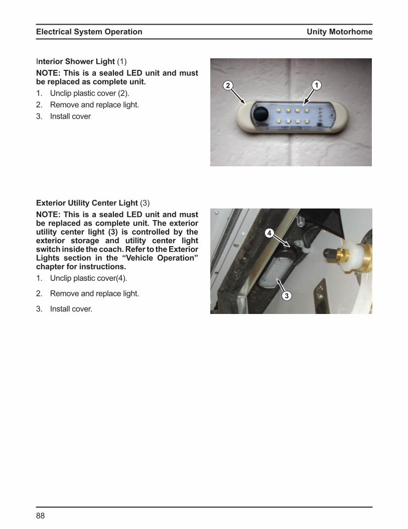
Unity Motorhome
88
2
Interior Shower Light (1)O his is a sealed L unit and must
be replaced as complete unit. 1. nclip plastic cover 22 Remove and replace light.3 Install cover
1
3
terior tilit Center Light 3O his is a sealed L unit and must
be replaced as complete unit. he e terior utilit center light 3 is controlled b the exterior storage and utility center light switch inside the coach. Refer to the Exterior Lights section in the Vehicle Operation chapter for instructions.1. nclip plastic cover
2 Remove and replace light.
3 Install cover.
4
Electrical System Operation
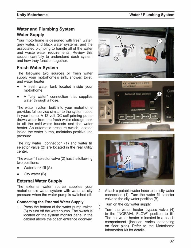
Unity Motorhome
89
Water lumbing S stem
Water and lumbing S stemWater SupplyYour motorhome is designed with fresh water, grey water, and black water systems, and the associated plumbing to handle all of the water and waste water requirements. Review this section carefully to understand each system and how they function together.
Fresh Water SystemThe following two sources or fresh water supply your motorhome’s sink, shower, toilet, and water heater:
A fresh water tank located inside your motorhome.
city water connection that supplies water through a hose.
The water system built into your motorhome provides full service similar to the system used in your ho e 12 volt C sel pri ing pu p draws water from the fresh water storage tank to all the cold water aucets and the water heater. An automatic pressure switch, located inside the water pump, maintains positive line pressure.
The city water connection 1 and water fill selector valve 2 are located in the rear utility center.
The water fill selector valve 2 has the ollowing two positions:
Water tank fill City water (B)
External Water SupplyThe external water source supplies your motorhome’s water system with water at city pressure when the water pump is switched off.
Connecting the External Water Supply1. Press the bottom of the water pump switch
3 to turn o the water pu p The switch is located on the system monitor panel in the cabinet above the coach entrance doorway.
2
3
1
2 Attach a potable water hose to the city water connection 1 Turn the water fill selector valve to the city water position (B).
3 Turn on the city water supply. Turn the water heater ypass valve
to the R L L W position to fill The hot water heater is located in a coach compartment (location varies depending on oor plan Re er to the otorho e Information Kit for details.
4
B
A
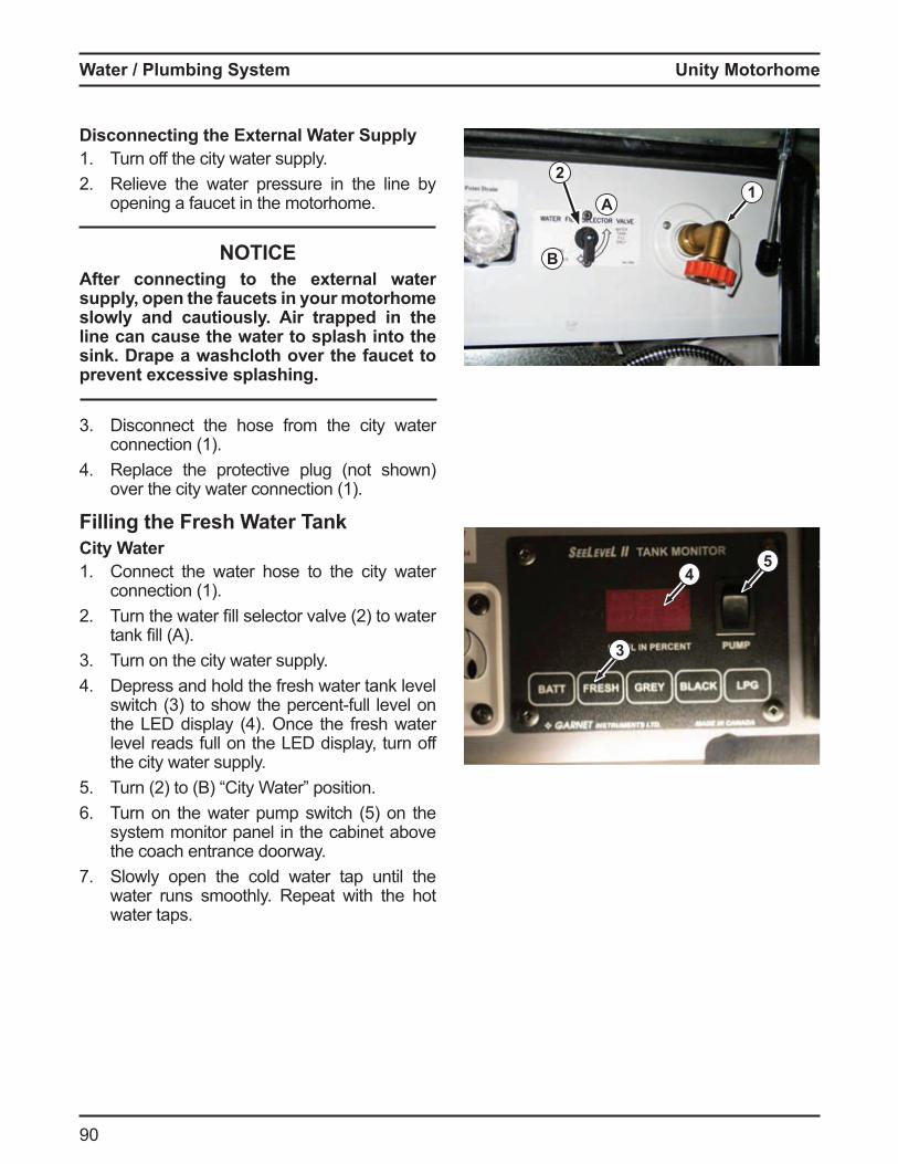
Unity Motorhome
90
5
Disconnecting the External Water Supply1. Turn off the city water supply.2 Relieve the water pressure in the line by
opening a faucet in the motorhome.
NOTICEAfter connecting to the external water supply, open the faucets in your motorhome slowly and cautiously. Air trapped in the line can cause the water to splash into the sink. Drape a washcloth over the faucet to prevent excessive splashing.
3 Disconnect the hose from the city water connection (1).
Replace the protective plug (not shown) over the city water connection (1).
Filling the Fresh Water TankCity Water1. Connect the water hose to the city water
connection (1).2 Turn the water fill selector valve 2 to water
tank fill 3 Turn on the city water supply.
Depress and hold the fresh water tank level switch 3 to show the percent ull level on the L display nce the resh water level reads full on the LED display, turn off the city water supply.
5 Turn 2 to City Water position Turn on the water pu p switch 5 on the
system monitor panel in the cabinet above the coach entrance doorway.
7. Slowly open the cold water tap until the water runs smoothly. Repeat with the hot water taps.
B
A
21
4
3
Water lumbing S stem
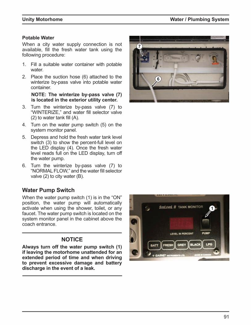
Unity Motorhome
91
Water lumbing S stem
otable WaterWhen a city water supply connection is not availa le, fill the resh water tank using the following procedure:
1. Fill a suitable water container with potable water.
2 Place the suction hose attached to the winteri e y pass valve into pota le water container.
O he winterize b pass valve is located in the exterior utility center.
3 Turn the winteri e y pass valve 7 to W T R , and water fill selector valve 2 to water tank fill
Turn on the water pu p switch 5 on the system monitor panel.
5 Depress and hold the fresh water tank level switch 3 to show the percent ull level on the L display nce the resh water level reads full on the LED display, turn off the water pump.
Turn the winteri e y pass valve 7 to R L L W, and the water fill selector
valve 2 to city water
Water ump SwitchWhen the water pu p switch 1 is in the position, the water pump will automatically activate when using the shower, toilet, or any faucet. The water pump switch is located on the system monitor panel in the cabinet above the coach entrance.
NOTICEAlways turn off the water pump switch (1) if leaving the motorhome unattended for an extended period of time and when driving to prevent e cessive damage and batter discharge in the event of a leak.
1
6
7
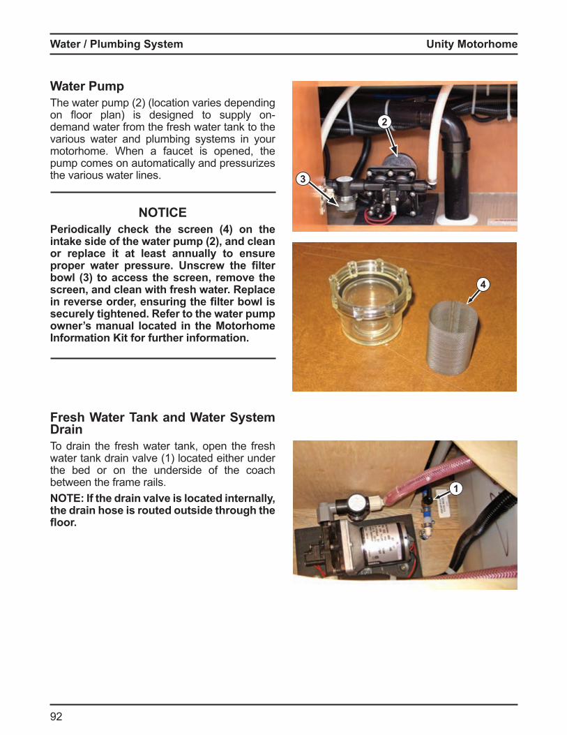
Unity Motorhome
92
Water umpThe water pu p 2 location varies depending on oor plan is designed to supply ondemand water from the fresh water tank to the various water and plumbing systems in your motorhome. When a faucet is opened, the pump comes on automatically and pressurizes the various water lines.
NOTICEeriodicall chec the screen on the
intake side of the water pump (2), and clean or replace it at least annually to ensure proper water pressure. nscrew the filter bowl 3 to access the screen remove the screen, and clean with fresh water. Replace in reverse order ensuring the filter bowl is securely tightened. Refer to the water pump owner’s manual located in the Motorhome Information Kit for further information.
Fresh Water Tank and Water System DrainTo drain the fresh water tank, open the fresh water tank drain valve (1) located either under the bed or on the underside of the coach between the frame rails.
O f the drain valve is located internall the drain hose is routed outside through the
oor.
4
1
2
3
Water lumbing S stem
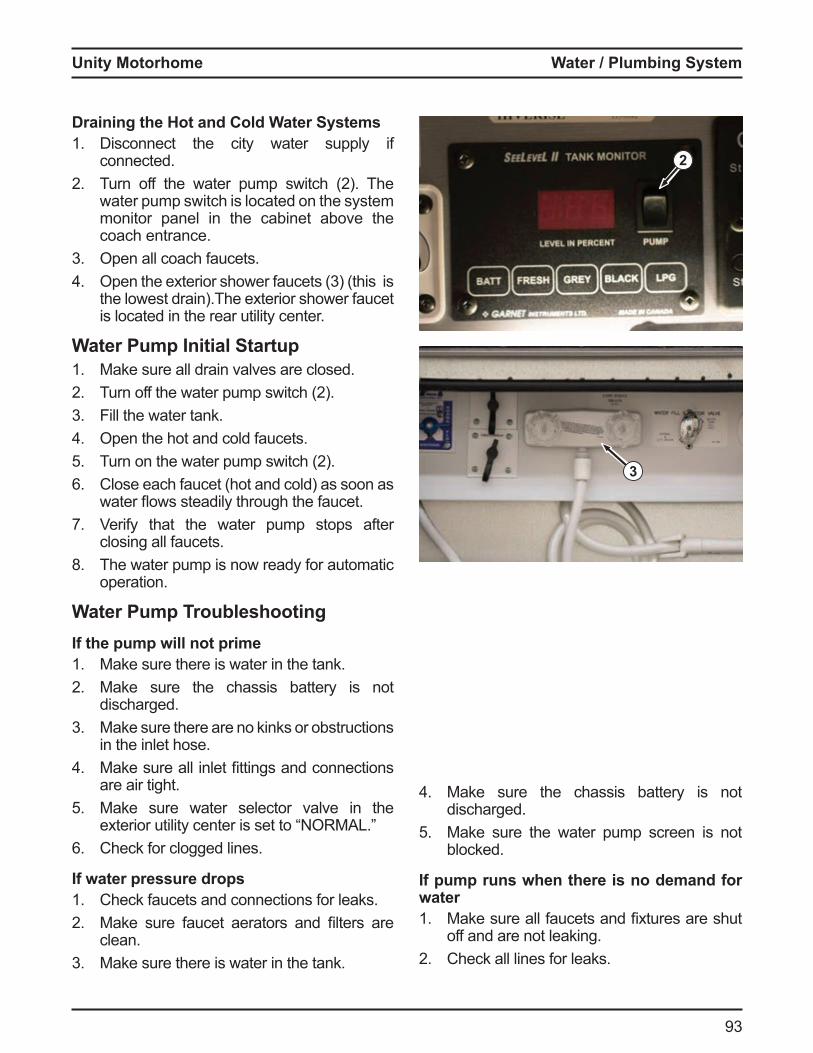
Unity Motorhome
93
Water lumbing S stem
2
Draining the Hot and Cold Water Systems1. Disconnect the city water supply if
connected.2 Turn o the water pu p switch 2 The
water pump switch is located on the system monitor panel in the cabinet above the coach entrance.
3 Open all coach faucets. pen the e terior shower aucets 3 this is
the lowest drain).The exterior shower faucet is located in the rear utility center.
Water ump nitial Startup1. Make sure all drain valves are closed.2 Turn o the water pu p switch 23 Fill the water tank.
Open the hot and cold faucets.5 Turn on the water pu p switch 2
Close each faucet (hot and cold) as soon as water ows steadily through the aucet
7. Verify that the water pump stops after closing all faucets.
8. The water pump is now ready for automatic operation.
Water ump roubleshootingIf the pump will not prime1. Make sure there is water in the tank.2 Make sure the chassis battery is not
discharged.3 Make sure there are no kinks or obstructions
in the inlet hose. ake sure all inlet fittings and connections
are air tight.5 Make sure water selector valve in the
e terior utility center is set to R L Check for clogged lines.
If water pressure drops1. Check faucets and connections for leaks.2 ake sure aucet aerators and filters are
clean.3 Make sure there is water in the tank.
Make sure the chassis battery is not discharged.
5 Make sure the water pump screen is not blocked.
If pump runs when there is no demand for water1. ake sure all aucets and fi tures are shut
off and are not leaking.2 Check all lines for leaks.
3
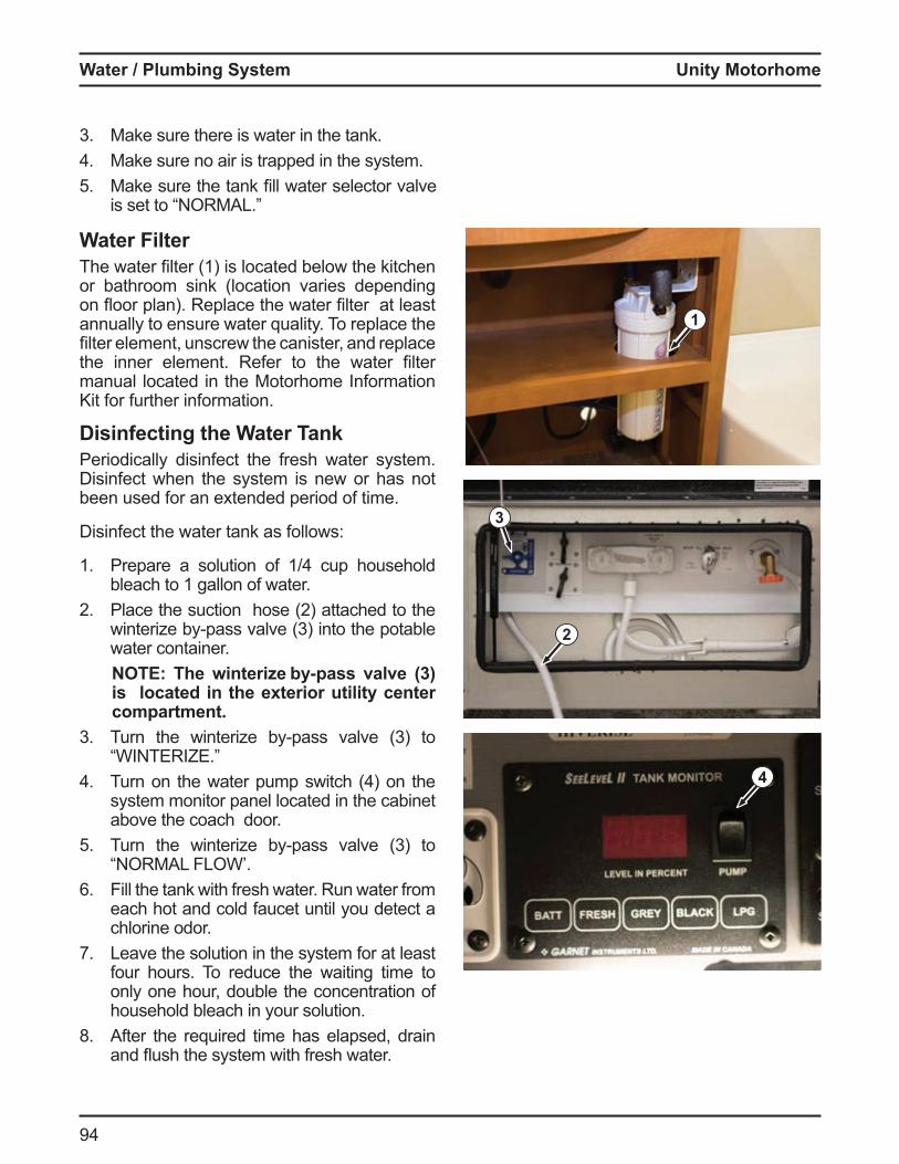
Unity Motorhome
9
3 Make sure there is water in the tank. Make sure no air is trapped in the system.
5 ake sure the tank fill water selector valve is set to R L
Water FilterThe water filter 1 is located elow the kitchen or bathroom sink (location varies depending on oor plan Replace the water filter at least annually to ensure water quality. To replace the filter ele ent, unscrew the canister, and replace the inner ele ent Re er to the water filter manual located in the Motorhome Information Kit for further information.
Disinfecting the Water TankPeriodically disinfect the fresh water system. Disinfect when the system is new or has not been used for an extended period of time.
Disinfect the water tank as follows:
1. Prepare a solution o 1 cup household bleach to 1 gallon of water.
2 Place the suction hose 2 attached to the winteri e y pass valve 3 into the pota le water container.
O he winterize b pass valve 3 is located in the exterior utility center compartment.
3 Turn the winteri e y pass valve 3 to W T R
Turn on the water pu p switch on the system monitor panel located in the cabinet above the coach door.
5 Turn the winteri e y pass valve 3 to “NORMAL FLOW’.
Fill the tank with fresh water. Run water from each hot and cold faucet until you detect a chlorine odor.
7. Leave the solution in the system for at least four hours. To reduce the waiting time to only one hour, double the concentration of household bleach in your solution.
8. After the required time has elapsed, drain and ush the syste with resh water
1
4
2
3
Water lumbing S stem
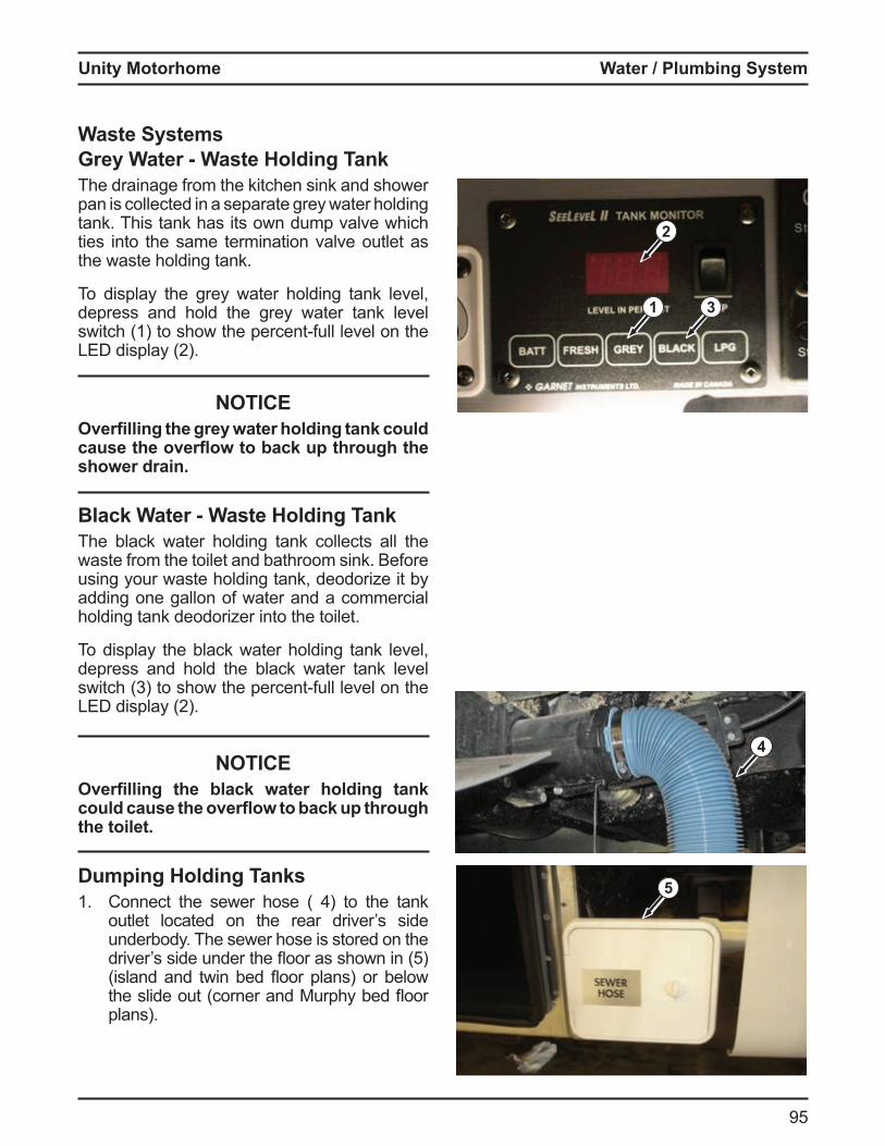
Unity Motorhome
95
Water lumbing S stem
Waste SystemsGrey Water - Waste Holding TankThe drainage from the kitchen sink and shower pan is collected in a separate grey water holding tank. This tank has its own dump valve which ties into the same termination valve outlet as the waste holding tank.
To display the grey water holding tank level, depress and hold the grey water tank level switch 1 to show the percent ull level on the L display 2
NOTICEOverfilling the gre water holding tan could cause the over ow to bac up through the shower drain.
Black Water - Waste Holding TankThe black water holding tank collects all the waste from the toilet and bathroom sink. Before using your waste holding tank, deodorize it by adding one gallon of water and a commercial holding tank deodorizer into the toilet.
To display the black water holding tank level, depress and hold the black water tank level switch 3 to show the percent ull level on the L display 2
NOTICEOverfilling the blac water holding tan could cause the over ow to bac up through the toilet.
Dumping Holding Tanks1. Connect the sewer hose to the tank
outlet located on the rear driver’s side underbody. The sewer hose is stored on the driver s side under the oor as shown in 5 island and twin ed oor plans or elow
the slide out corner and urphy ed oor plans).
5
4
1 3
2
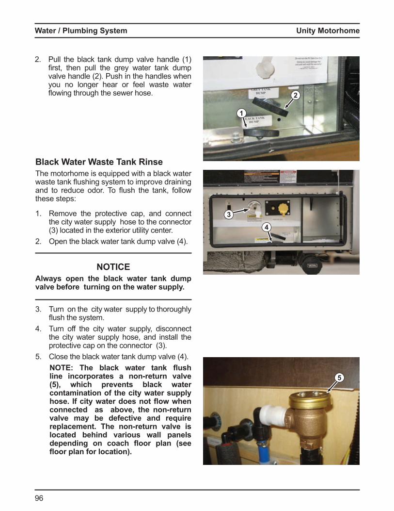
Unity Motorhome
9
2 Pull the black tank dump valve handle (1) first, then pull the grey water tank du p valve handle 2 Push in the handles when you no longer hear or feel waste water owing through the sewer hose 2
1
3
Black Water Waste Tank RinseThe motorhome is equipped with a black water waste tank ushing syste to i prove draining and to reduce odor To ush the tank, ollow these steps:
1. Remove the protective cap, and connect the city water supply hose to the connector 3 located in the e terior utility center
2 pen the lack water tank du p valve
NOTICElwa s open the blac water tan dump
valve before turning on the water suppl .
3 Turn on the city water supply to thoroughly ush the syste
Turn off the city water supply, disconnect the city water supply hose, and install the protective cap on the connector 3
5 Close the lack water tank du p valve O he blac water tan ush
line incorporates a non-return valve which prevents blac water
contamination of the city water supply hose. f cit water does not ow when connected as above the non return valve ma be defective and re uire replacement. The non-return valve is located behind various wall panels depending on coach oor plan see
oor plan for location .
4
5
Water lumbing S stem
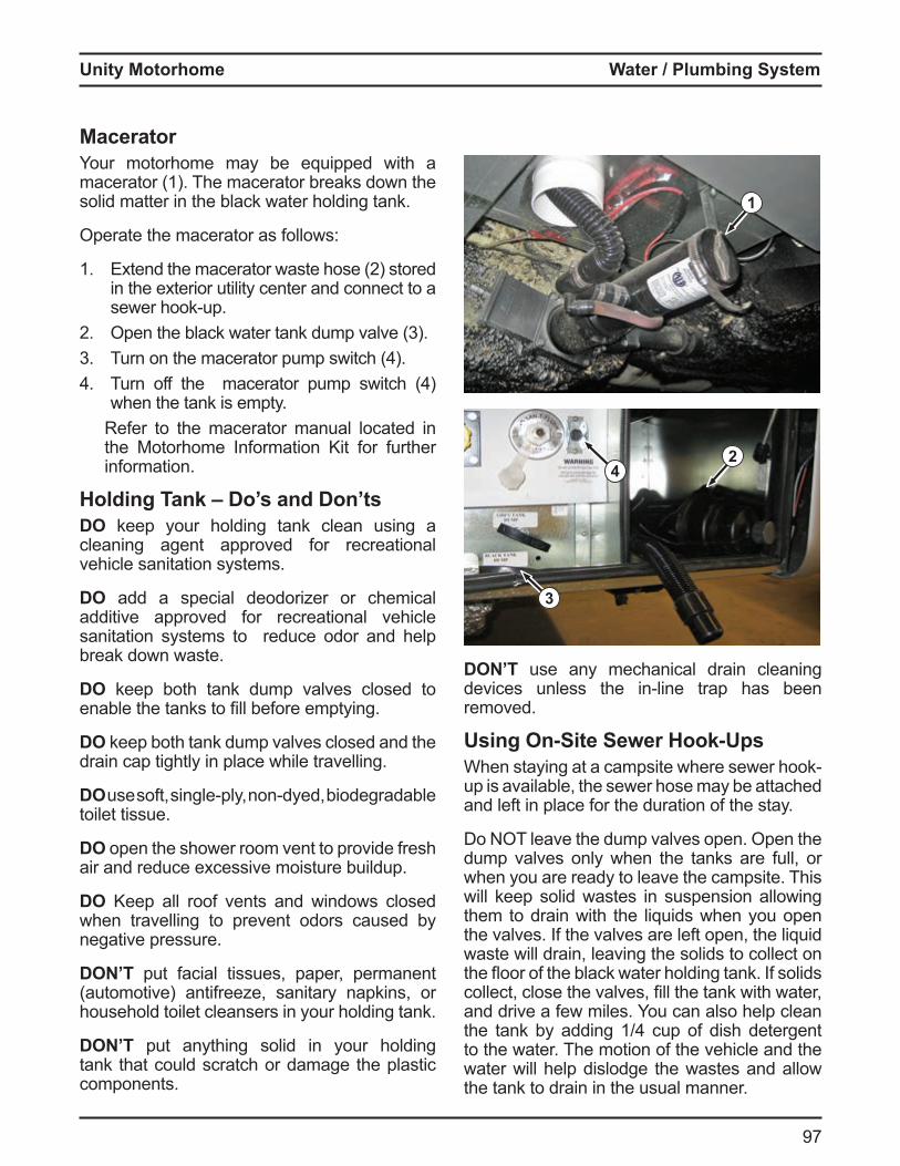
Unity Motorhome
97
Water lumbing S stem
MaceratorYour motorhome may be equipped with a macerator (1). The macerator breaks down the solid matter in the black water holding tank.
Operate the macerator as follows:
1. tend the acerator waste hose 2 stored in the exterior utility center and connect to a sewer hook up
2 pen the lack water tank du p valve 33 Turn on the acerator pu p switch
Turn o the acerator pu p switch when the tank is empty.
Refer to the macerator manual located in the Motorhome Information Kit for further information.
Holding Tank – Do’s and Don’tsDO keep your holding tank clean using a cleaning agent approved for recreational vehicle sanitation systems.
DO add a special deodorizer or chemical additive approved for recreational vehicle sanitation systems to reduce odor and help break down waste.
DO keep both tank dump valves closed to ena le the tanks to fill e ore e ptying
DO keep both tank dump valves closed and the drain cap tightly in place while travelling.
DO use so t, single ply, non dyed, iodegrada le toilet tissue.
DO open the shower room vent to provide fresh air and reduce excessive moisture buildup.
DO Keep all roof vents and windows closed when travelling to prevent odors caused by negative pressure.
DON’T put facial tissues, paper, permanent (automotive) antifreeze, sanitary napkins, or household toilet cleansers in your holding tank.
DON’T put anything solid in your holding tank that could scratch or damage the plastic components.
1
2
DON’T use any mechanical drain cleaning devices unless the in line trap has een removed.
Using On-Site Sewer Hook-UpsWhen staying at a ca psite where sewer hookup is available, the sewer hose may be attached and left in place for the duration of the stay.
Do NOT leave the dump valves open. Open the dump valves only when the tanks are full, or when you are ready to leave the campsite. This will keep solid wastes in suspension allowing them to drain with the liquids when you open the valves. If the valves are left open, the liquid waste will drain, leaving the solids to collect on the oor o the lack water holding tank solids collect, close the valves, fill the tank with water, and drive a few miles. You can also help clean the tank y adding 1 cup o dish detergent to the water. The motion of the vehicle and the water will help dislodge the wastes and allow the tank to drain in the usual manner.
4
3
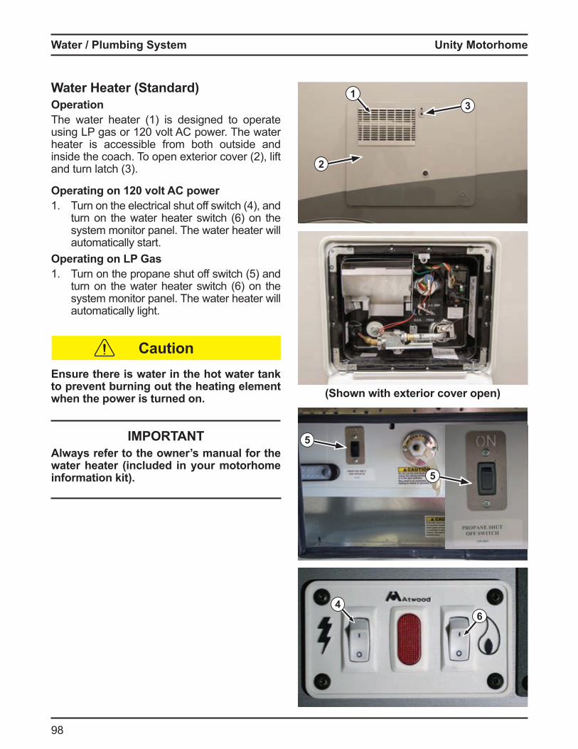
Unity Motorhome
98
1
5
3
6
Caution
5
(Shown with exterior cover open)
Water Heater (Standard)OperationThe water heater (1) is designed to operate using LP gas or 120 volt C power The water heater is accessible from both outside and inside the coach To open e terior cover 2 , li t and turn latch 3
Operating on 120 volt AC power1. Turn on the electrical shut o switch , and
turn on the water heater switch on the system monitor panel. The water heater will automatically start.
Operating on L as1. Turn on the propane shut o switch 5 and
turn on the water heater switch on the system monitor panel. The water heater will automatically light.
4
Ensure there is water in the hot water tank to prevent burning out the heating element when the power is turned on.
2
Water lumbing S stem
OAlways refer to the owner’s manual for the water heater (included in your motorhome information kit).
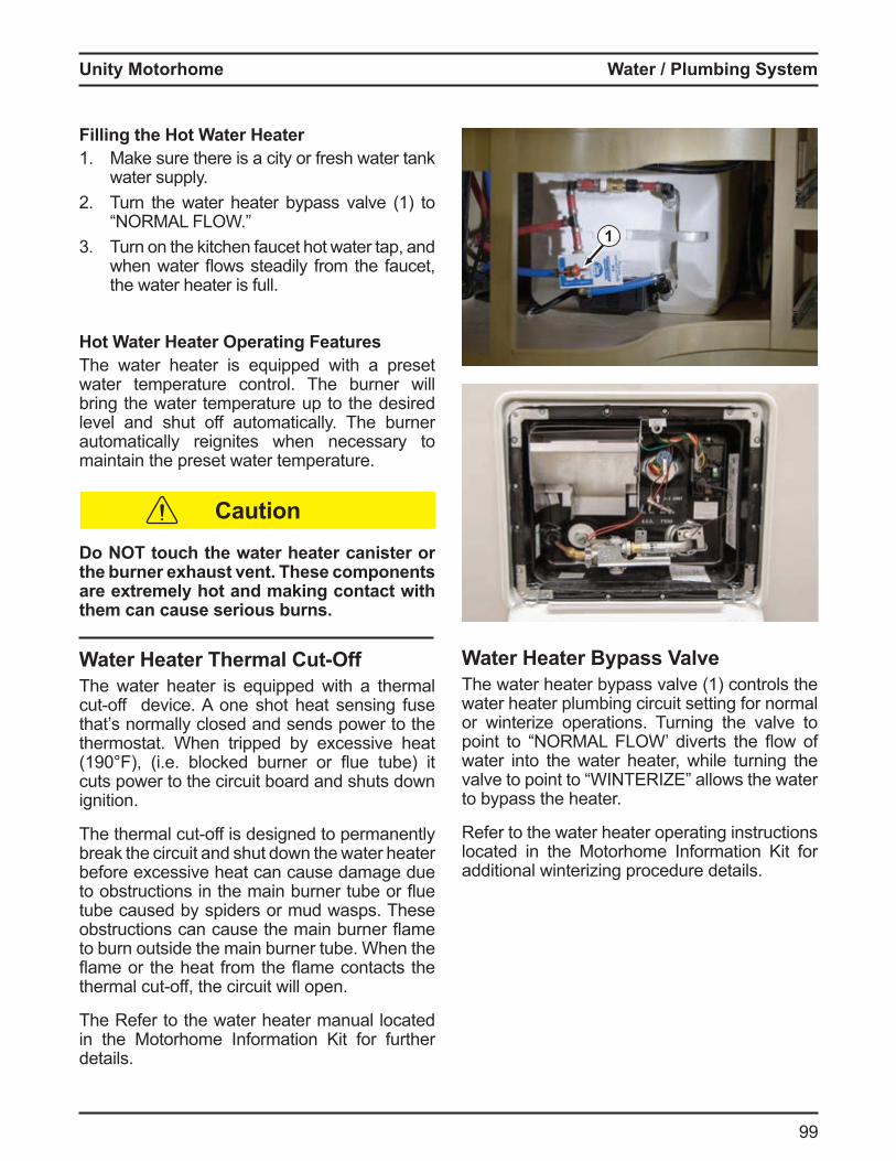
Unity Motorhome
99
Water lumbing S stem
Filling the Hot Water Heater1. Make sure there is a city or fresh water tank
water supply.2 Turn the water heater bypass valve (1) to
R L L W3 Turn on the kitchen faucet hot water tap, and
when water ows steadily ro the aucet, the water heater is full.
Hot Water Heater Operating FeaturesThe water heater is equipped with a preset water temperature control. The burner will bring the water temperature up to the desired level and shut off automatically. The burner automatically reignites when necessary to maintain the preset water temperature.
Do NOT touch the water heater canister or the burner e haust vent. hese components are extremely hot and making contact with them can cause serious burns.
Water Heater Thermal Cut-OffThe water heater is equipped with a thermal cut o device one shot heat sensing use that’s normally closed and sends power to the thermostat. When tripped by excessive heat 190 , i e locked urner or ue tu e it
cuts power to the circuit board and shuts down ignition.
The ther al cut o is designed to per anently break the circuit and shut down the water heater before excessive heat can cause damage due to o structions in the ain urner tu e or ue tube caused by spiders or mud wasps. These o structions can cause the ain urner a e to burn outside the main burner tube. When the a e or the heat ro the a e contacts the
ther al cut o , the circuit will open
The Refer to the water heater manual located in the Motorhome Information Kit for further details.
Caution
Water Heater Bypass ValveThe water heater bypass valve (1) controls the water heater plumbing circuit setting for normal or winterize operations. Turning the valve to point to R L L W diverts the ow o water into the water heater, while turning the valve to point to W T R allows the water to bypass the heater.
Refer to the water heater operating instructions located in the Motorhome Information Kit for additional winterizing procedure details.
1
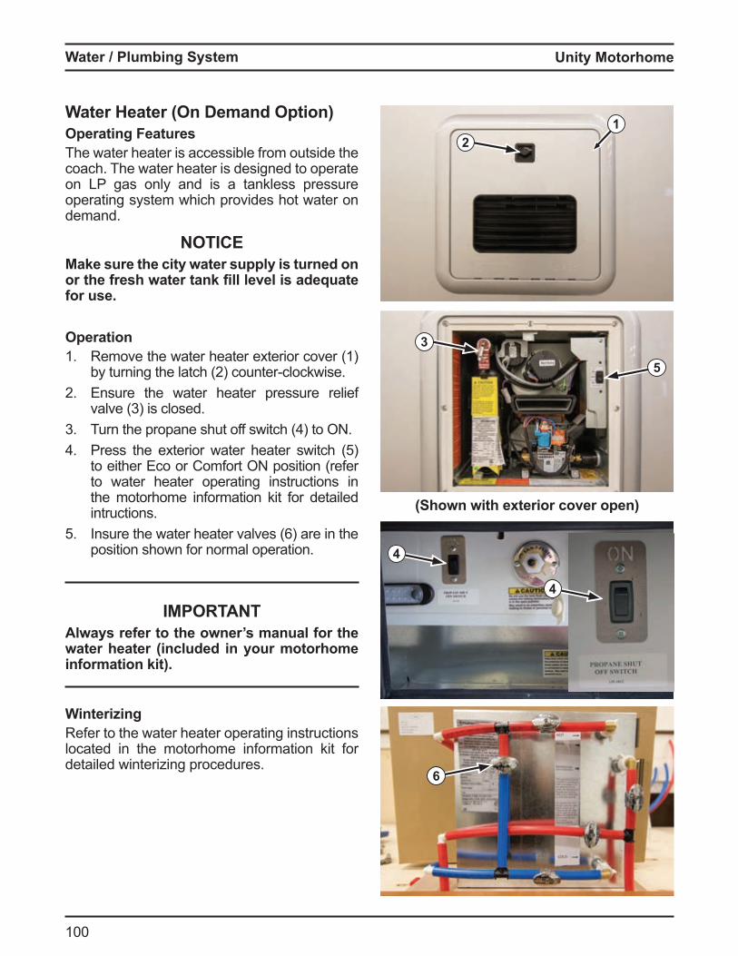
Unity Motorhome
100
Water lumbing S stem
Water Heater (On Demand Option)Operating FeaturesThe water heater is accessible from outside the coach. The water heater is designed to operate on LP gas only and is a tankless pressure operating system which provides hot water on demand.
NOTICEMake sure the city water supply is turned on or the fresh water tan fill level is ade uate for use.
Operation1. Remove the water heater exterior cover (1)
y turning the latch 2 counter clockwise2 Ensure the water heater pressure relief
valve 3 is closed3 Turn the propane shut o switch to
Press the e terior water heater switch 5 to either Eco or Comfort ON position (refer to water heater operating instructions in the motorhome information kit for detailed intructions.
5 nsure the water heater valves are in the position shown for normal operation.
OAlways refer to the owner’s manual for the water heater (included in your motorhome information kit).
WinterizingRefer to the water heater operating instructions located in the motorhome information kit for detailed winterizing procedures.
4
4
(Shown with exterior cover open)
12
3
5
6
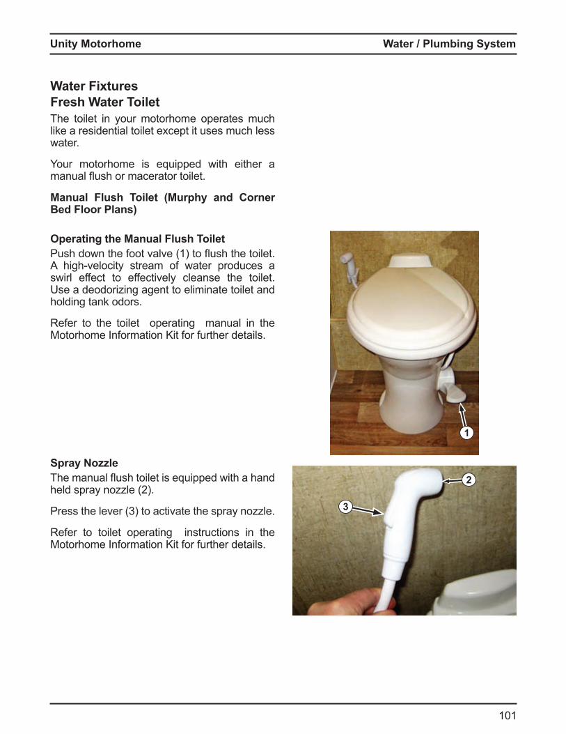
Unity Motorhome
101
Water lumbing S stem
Water FixturesFresh Water ToiletThe toilet in your motorhome operates much like a residential toilet except it uses much less water.
Your motorhome is equipped with either a anual ush or acerator toilet
Manual Flush Toilet (Murphy and Corner ed loor lans
Operating the Manual Flush ToiletPush down the oot valve 1 to ush the toilet
high velocity strea o water produces a swirl effect to effectively cleanse the toilet. Use a deodorizing agent to eliminate toilet and holding tank odors.
Refer to the toilet operating manual in the Motorhome Information Kit for further details.
Spray NozzleThe anual ush toilet is e uipped with a hand held spray no le 2
Press the lever 3 to activate the spray no le
Refer to toilet operating instructions in the Motorhome Information Kit for further details.
1
3
2
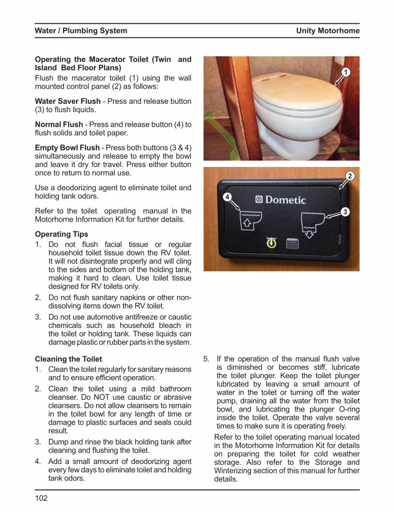
Unity Motorhome
102
Water lumbing S stem
1
2
3
4
Cleaning the Toilet1. Clean the toilet regularly for sanitary reasons
and to ensure e ficient operation2 Clean the toilet using a mild bathroom
cleanser. Do NOT use caustic or abrasive cleansers. Do not allow cleansers to remain in the toilet bowl for any length of time or damage to plastic surfaces and seals could result.
3 Dump and rinse the black holding tank after cleaning and ushing the toilet
Add a small amount of deodorizing agent every few days to eliminate toilet and holding tank odors.
Operating the Macerator Toilet (Twin and sland ed loor lansFlush the macerator toilet (1) using the wall
ounted control panel 2 as ollows
Water Saver Flush Press and release utton 3 to ush li uids
Normal Flush Press and release utton to ush solids and toilet paper
Empty Bowl Flush Press oth uttons 3 simultaneously and release to empty the bowl and leave it dry for travel. Press either button once to return to normal use.
Use a deodorizing agent to eliminate toilet and holding tank odors.
Refer to the toilet operating manual in the Motorhome Information Kit for further details.
Operating Tips1. o not ush acial tissue or regular
household toilet tissue down the RV toilet. It will not disintegrate properly and will cling to the sides and bottom of the holding tank, making it hard to clean. Use toilet tissue designed for RV toilets only.
2 o not ush sanitary napkins or other nondissolving items down the RV toilet.
3 Do not use automotive antifreeze or caustic chemicals such as household bleach in the toilet or holding tank. These liquids can damage plastic or rubber parts in the system.
5 the operation o the anual ush valve is diminished or becomes stiff, lubricate the toilet plunger. Keep the toilet plunger lubricated by leaving a small amount of water in the toilet or turning off the water pump, draining all the water from the toilet owl, and lu ricating the plunger ring
inside the toilet. Operate the valve several times to make sure it is operating freely.
Refer to the toilet operating manual located in the Motorhome Information Kit for details on preparing the toilet for cold weather storage. Also refer to the Storage and Winterizing section of this manual for further details.
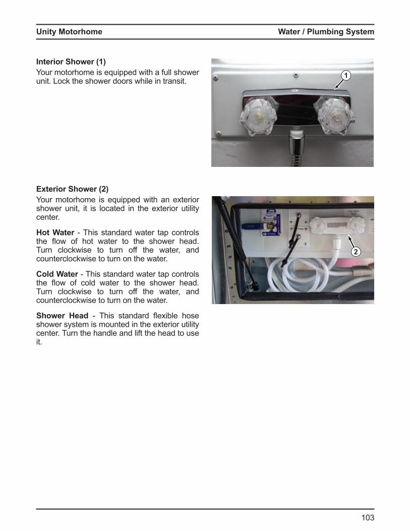
Unity Motorhome
103
Water lumbing S stem
Interior Shower (1)Your motorhome is equipped with a full shower unit. Lock the shower doors while in transit.
Exterior Shower (2)Your motorhome is equipped with an exterior shower unit, it is located in the exterior utility center.
Hot Water This standard water tap controls the ow o hot water to the shower head Turn clockwise to turn off the water, and counterclockwise to turn on the water.
Cold Water This standard water tap controls the ow o cold water to the shower head Turn clockwise to turn off the water, and counterclockwise to turn on the water.
Shower Head This standard e i le hose shower system is mounted in the exterior utility center. Turn the handle and lift the head to use it.
1
2
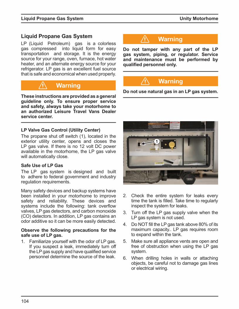
Unity Motorhome
10
Li uid ropane as S stem
Li uid ropane as S stemLP (Liquid Petroleum) gas is a colorless gas compressed into liquid form for easy transportation and storage. It is the energy source for your range, oven, furnace, hot water heater, and an alternate energy source for your refrigerator. LP gas is an excellent fuel source that is safe and economical when used properly.
These instructions are provided as a general guideline only. To ensure proper service and safety, always take your motorhome to an authorized Leisure ravel Vans ealer service center.
L Valve as Control tilit CenterThe propane shut off switch (1), located in the exterior utility center, opens and closes the LP gas valve there is no 12 volt C power available in the motorhome, the LP gas valve will automatically close.
Safe se of L asThe LP gas system is designed and built to adhere to federal government and industry regulation requirements.
Many safety devices and backup systems have been installed in your motorhome to improve safety and reliability. These devices and syste s include the ollowing tank over ow valves, LP gas detectors, and carbon monoxide (CO) detectors. In addition, LP gas contains an odor additive so it can be more easily detected.
Observe the following precautions for the safe use of L gas.1. Familiarize yourself with the odor of LP gas.
If you suspect a leak, immediately turn off the LP gas supply and have ualified service personnel determine the source of the leak.
1
o not tamper with an part of the L gas system, piping, or regulator. Service and maintenance must be performed b
ualified personnel onl .
o not use natural gas in an L gas s stem.
2 Check the entire system for leaks every ti e the tank is filled Take ti e to regularly inspect the system for leaks.
3 Turn off the LP gas supply valve when the LP gas system is not used.
o T fill the LP gas tank a ove 80 o its maximum capacity.. LP gas requires room to expand within the tank.
5 Make sure all appliance vents are open and free of obstruction when using the LP gas system.
When drilling holes in walls or attaching objects, be careful not to damage gas lines or electrical wiring.
Warning
Warning
Warning
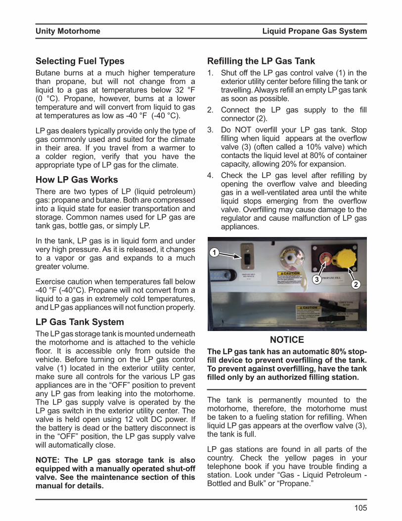
Unity Motorhome
105
Li uid ropane as S stem
Selecting Fuel TypesButane burns at a much higher temperature than propane, but will not change from a li uid to a gas at te peratures elow 32 0 C Propane, however, urns at a lower
temperature and will convert from liquid to gas at te peratures as low as 0 0 C
LP gas dealers typically provide only the type of gas commonly used and suited for the climate in their area. If you travel from a warmer to a colder region, verify that you have the appropriate type of LP gas for the climate.
ow L as Wor sThere are two types of LP (liquid petroleum) gas: propane and butane. Both are compressed into a liquid state for easier transportation and storage. Common names used for LP gas are tank gas, bottle gas, or simply LP.
In the tank, LP gas is in liquid form and under very high pressure. As it is released, it changes to a vapor or gas and expands to a much greater volume.
Exercise caution when temperatures fall below 0 0 C Propane will not convert ro a
liquid to a gas in extremely cold temperatures, and LP gas appliances will not function properly.
L as an S stemThe LP gas storage tank is mounted underneath the motorhome and is attached to the vehicle oor t is accessi le only ro outside the
vehicle. Before turning on the LP gas control valve (1) located in the exterior utility center, make sure all controls for the various LP gas appliances are in the position to prevent any LP gas from leaking into the motorhome. The LP gas supply valve is operated by the LP gas switch in the exterior utility center. The valve is held open using 12 volt C power the battery is dead or the battery disconnect is in the position, the LP gas supply valve will automatically close.
O he L gas storage tan is also equipped with a manually operated shut-off valve. See the maintenance section of this manual for details.
1
23
efilling the L as an1. Shut off the LP gas control valve (1) in the
e terior utility center e ore filling the tank or travelling lways refill an e pty LP gas tank as soon as possible.
2 Connect the LP gas supply to the fill connector 2
3 o T overfill your LP gas tank Stop filling when li uid appears at the over ow valve 3 o ten called a 10 valve which contacts the li uid level at 80 o container capacity, allowing 20 or e pansion
Check the LP gas level a ter refilling y opening the over ow valve and leeding gas in a well ventilated area until the white li uid stops e erging ro the over ow valve verfilling ay cause da age to the regulator and cause malfunction of LP gas appliances.
NOTICEhe L gas tan has an automatic stop
fill device to prevent overfilling of the tan . o prevent against overfilling have the tan
filled onl b an authorized filling station.
The tank is permanently mounted to the motorhome, therefore, the motorhome must e taken to a ueling station or refilling When
li uid LP gas appears at the over ow valve 3 , the tank is full.
LP gas stations are found in all parts of the country. Check the yellow pages in your telephone ook i you have trou le finding a station Look under Gas Li uid Petroleu
ottled and ulk or Propane

Unity Motorhome
10
Li uid ropane as S stem
Warning
Dangero O smo e when refueling. eep ames
sparks, and smoking material away from fuel or ammable fumes.
ever overfill the LP gas tank ake sure your otorho e is level when filling the tank.
Make sure all pilot lights are off before refueling any of the gas tanks on your motorhome.
o not s oke or have any open a e in the area where refueling is taking place.
Use a soap and water solution to test for leaks in the LP gas system.
ever use an open a e to test or leaks ever fill the LP gas tank when either the
engine or the generator is running. Keep all protective covers and caps in
place.
ever carr L gas or an other ammable liquid containers inside the living or driving areas of your motorhome. Gases ma inadvertentl be discharged into the confined space which could result in fire asphyxiation, or explosion.
Remind the service attendant to use the over ow valve when refueling. Space
must be left in the tan for vaporization and expansion to occur.
fter refilling the L gas tan1. Periodically check all container and line
connections to be sure they are tight. Use soapy water when testing for leaks—do
T use an open a e2 If you notice diesel or LP gas fumes at any
time, immediately determine and correct the source of the problem.
3 Before opening the LP gas control valve in the exterior utility center, check that controls for all gas appliances are in the
position n accu ulation o LP gas inside the otorho e could create a fire or explosion hazard.
Remember, LP gas is potentially lethal if inhaled.
ir in the L as anIf your LP gas appliances burn poorly or do not stay lit even though there is a su ficient uel supply, there may be air trapped in the LP gas tank. The air should eventually escape along with the LP gas, but it may be necessary to have your LP gas tank purged of air by your LP gas dealer.
Danger
Danger
Warning
Unity Motorhome
107
Li uid ropane as S stem
ravelling with L as
NOTICEIn some jurisdictions it is illegal to transport L gas on certain roads or through tunnels. Check state or provincial regulations to ma e sure our trip will not be halted or impeded unexpectedly as a result of transporting L gas.
L as an egulatorThe LP gas tank regulator has a plastic cover to protect it ro the weather nly ualified service personnel are permitted to remove this cover.
The pressure regulator has a vent hole on the underside. Make sure this vent hole is open and not obstructed in any way.
An LP gas regulator may freeze in extremely cold temperatures. This may result from a small amount of moisture in the fuel, even though LP gas dealers take precautions to prevent this from happening. Keep the LP gas control valve closed when not in use, even when the LP gas tank is empty. This helps to prevent condensation from forming and helps to prevent freezing. If necessary, hold a light bulb near the regulator to thaw it.
If moisture in the LP gas tank is a recurring problem, ask your LP gas dealer to inject a small amount of dry methyl alcohol into the tank to absorb the moisture.
LP gas vaporizes quickly and easily in warmer temperatures. In colder conditions, this vapori ation process significantly slows down When large amounts of fuel are required, when using the furnace for example, the fuel may not vaporize rapidly enough to keep all the appliances operating at a high level. In this case, you may have to reduce the consumption of fuel by lowering the temperature setting on the furnace, reducing the consumption of hot water, turning down the temperature setting on your refrigerator, or switching from LP gas to electric power if possible.
The LP gas regulator pressure is preset. Do NOT attempt to adjust it. Adjustments must only be performed by an authorized service outlet. Do NOT expose the regulator to the elements.
If the LP gas regulator fails, the LP gas tank ay e overfilled or i purities ay i with the
propane. Regulator failure could cause LP gas components to malfunction.
o not use an open ame or a heat lamp to thaw the regulator.
L as Lea sRead, understand, and follow the safety label a fi ed near the range area in your otorho e s galley. Do NOT remove this label. If you ever smell LP gas inside the vehicle or if the detector alarm sounds, carefully follow the instructions on the label.
Road vi ration can loosen propane fittings Check the propane system for leaks at least every 5000 iles 8000 s and whenever the tank is refilled ave the entire propane syste inspected annually y ualified service personnel regardless of the number of miles driven.
1. Read, understand, and follow safety labels, signs, and directions in the motorhome.
2 Use soapy water to check for leaks and watch or u les ever use an open a e
3 Correct or repair leaks before using appliances or operating the vehicle.
Caution
Unity Motorhome
108
Li uid ropane as S stem
f ou smell propane follow these steps1. tinguish all open a es, pilot lights, and
smoking materials.2 Do NOT touch any electrical switches.3 Shut off the propane supply at the tank
valves or propane supply connections. Open doors, windows, and vents.
5 Leave the area until the odor clears. Have the propane system checked and
repaired y a ualified service technician before using the LP gas system. Failure to co ply could result in asphy iation, fire, or explosion causing serious injury or death.
Avoiding Asphyxiation1. o not use porta le uel urning e uip ent
such as wood or charcoal grills, heaters, or stoves inside the motorhome. The use of this equipment can produce deadly carbon
ono ide gas or cause fires
o not bring or store L gas containers gasoline or other ammable li uids inside the vehicle because a fire or e plosion ma result.
Do not use materials that contain ammonia or chlorine to chec for L gas lea s.
2 Ensure there is proper ventilation before using the gas range to prevent asphyxiation. Do NOT use the range to heat the vehicle. Long ter use o these appliances or space heating increases the chance of asphyxiation. Open the overhead vent and open a window before using the range.
Warning
Danger
Warning
3 Avoid breathing the exhaust fumes from gas or diesel engines and LP gas burners. Poisonous exhaust fumes are produced from operating the motorhome or generator engine, stove, oven, refrigerator, furnace, and hot water heater. Position the motorhome so the wind blows exhaust fumes away from the vehicle. Ensure proper ventilation and adequate air exchange when using LP gas appliances to prevent a buildup of deadly carbon monoxide gas. Be sure all alarms are in proper working condition.
Do not run the motorhome or generator engine in a confined area such as a garage except to remove the vehicle from the confined area
5 Use the vent or air conditioning fan to force fresh air into the vehicle if the vehicle is not moving but the engine is running for more than just a few minutes.
Maintain engine and generator exhaust system components to prevent fumes from entering the motorhome. Check exhaust systems when changing oil, when exhaust system sounds change, or when the underbody of the motorhome makes contact with an object or becomes damaged.
7. Close rear windows when driving to prevent drawing exhaust fumes into the vehicle.
O When the motorhome is new some of the appliances will burn off paint or residue which has accumulated during production. You also may notice some odors from cleaners which will dissipate with use and ventilation.
Unity Motorhome
109
Motorhome Maintenance
Motorhome MaintenanceExterior Care and MaintenanceRoofThe roof is manufactured with a bowed aluminum frame and constructed using a laminated ‘sandwich’ method. It is strong enough to support the weight of an average adult if it becomes necessary to repair the roof or any of the roof mounted components. Avoid carrying large, heavy objects onto the roof. The additional strain of the weight along with the movement of the vehicle could cause damage to the roof. Check the roof regularly for possible leaks, especially the sealant around the vents, air conditioners, ody to roo sea s, etc Immediately repair any suspected leaks. Any leakage could result in damage to the interior of the motorhome.
nderbodMud and dirt mixed with corrosive materials used to control dust or ice on the roads can accumulate underneath your motorhome and cause premature deterioration and rusting. In addition, any build up will add unnecessary weight to the otorho e Rinse and ush the undercarriage and the entire underbody every time you wash the motorhome.
Washing Wa ing and olishingDamaging salts, calcium chloride, road tar, tree sap, insects, and other foreign material can accumulate on the body of your motorhome. To reduce the harmful effects of these agents, wash the motorhome frequently and thoroughly using mild soap and warm water. Do not wash the exterior in direct sunlight and never use hot water. Avoid using pressure washers because they can loosen decals and sealants. Regularly wax your RV to reduce the negative effects of
e posure on the e terior fi erglass parts
Carefully inspect all caulking around windows, doors, vents, and all other oints Re caulk i necessary using the correct caulking material available from your Leisure Travel Vans dealer. If water fails to bead on the surface of the motorhome, it is time to polish and wax it.
This will not only improve the appearance of your motorhome, but will also protect the painted surfaces from oxidation and corrosion making it easier to wash.
NOTICEThese instructions are provided as a general guideline onl and ma not be complete. o ensure proper service and safety, always take your motorhome to an authorized Leisure ravel Vans dealer service center.
Stripes and DecalsFollow these steps for the care and maintenance of your motorhome’s stripes and decals:
Wash with mild soap and warm water, and rinse thoroughly.
ever wash using a high pressure washer at close range. The force of the water can lift the edges of decals.
Do not use solvents. They can smear the colors and damage the adhesive.
Never use lacquer thinner or paint on decals.
Avoid splashing gasoline or diesel fuel on stripes and decals, and rinse immediately if splashing occurs.
terior LightingBefore each trip, inspect all clearance lights, identification lights, arker lights, stop lights, turn signal lights, and backup lights. Immediately replace burned out bulbs. Use soap and water to keep all light lenses clean.
Unity Motorhome
110
Motorhome Maintenance
Interior CareDirt and dust accumulation can not only detract from the motorhome’s appearance, but can also shorten the life of carpets and fabrics. Clean and vacuum weekly to keep your motorhome in pristine condition.
CarpetsRefer to the carpet manufacturer’s recommendations for carpet cleaning and care, and for information about stain removal.
UpholsteryUse care when cleaning the motorhome’s upholstery, and choose an appropriate cleaner or spot remover to avoid damaging the materials. Regular vacuuming and wiping with clear water will remove most stains. Any major cleaning problems should be referred to a professional cleaning service.
NOTICEDirect sunlight will fade upholstery and fabrics. o minimize fading close drapes blinds and shades whenever possible.
Spots and StainsMost spots and stains can be removed using clear warm water. To prevent the stain from spreading, start from the outside of the stain and work towards the center.
Stains such as lipstick, grease, ink, or mustard are very hard to remove and might require the help of a professional cleaning service.
Vin l abricsClean vinyl surfaces using a soft, damp cloth and mild detergent. Never use solvents of any kind on vinyl surfaces.
O he vin l manufacturer recommends the following o clean most common household stains use warm, soapy water, and a clear water rinse. or more stubborn stains, Fantastik™ or Mr. Clean™ diluted 3 1 with water are recommended.
Draperies, Curtains, and BedspreadsDraperies, curtains, and bedspreads are made from a variety of fabrics and materials.
any o these aterials could shrink up to 5 percent during the cleaning process. Always use a professional cleaning service for you motorhome’s textiles.
NOTICEsing water based or detergent based
solvent cleaners on fabrics ma cause excessive shrinkage and permanent stains.
WallsClean walls using warm water and mild soap. For extensive accumulations of dirt and grime, add a small quantity of rubbing alcohol to the water. Do NOT use solvents or abrasives.
Unity Motorhome
111
Motorhome Maintenance
Cabinetr ables and CountertopsThe wood’s beauty comes from the natural variations in grain and density. Some minor variations in color and shading are normal.
SinksThe sinks can be cleaned with warm water and soap. Wipe dry to avoid streaks. For stubborn stains, a mild abrasive may be necessary. Always work in the direction of the polish lines.
NOTICESome units contain acr lic le iglas components. Refer to the acrylic manufacturer’s cleaning instructions. Do NOT clean using Windex® style glass cleaners.
RefrigeratorClean the refrigerator interior regularly. Remove the shelves and wash inside the refrigerator using warm water and mild soap. Dry thoroughly, especially around door frame and door gasket. Use only warm water to clean the cooling evaporator, ice trays, and shelves. Never use strong chemicals or abrasive cleaning materials on any part of the refrigerator cabinet. Refer to the refrigerator manual in the Motorhome Information Kit for additional information.
Stove Top - GeneralClean the stove top as soon as it cools using warm water and a mild detergent solution. Clean the stove top regularly to help keep the appliance looking and operating like new.
Stove Top - BurnersClean the stove top burners (caps and grates) after they have cooled using warm water and a mild detergent solution. Clean plugged burner ports with a toothpick. Do NOT clean burner ports using metal objects of any kind because it could enlarge the port.
If washing a cap or grate in the sink, dry it immediately by shaking off all excess water, reinstalling it onto the stove top, and lighting the burner until all water evaporates.
Microwave/Convention OvenKeep the door and inside of your microwave/convection oven clean. Do not allow grease, spatter, or solid matter to build up. An accumulation of solid matter can absorb microwave energy and increase cooking time. Clean the microwave/convection oven as follows:
Wipe walls with a damp cloth and mild detergent to remove spatters and spills. Do not use harsh detergents or abrasives.
Clean the outside surface of the oven with soap and water. Rinse and dry with a soft cloth. Do NOT allow water to enter the oven’s ventilation openings to avoid damaging the oven’s internal components.
If the control panel becomes wet, clean it with a soft, dry cloth. Do not use harsh detergents or abrasives on the control panel. When cleaning the control panel, leave the oven door open to prevent the oven from accidentally turning on. After cleaning, touch the cancel pad to clear the display window. Remove the glass tray for cleaning. Wash the tray in warm, soapy water or in a dishwasher.
Refer to the microwave/convection oven manual in the Motorhome Information Kit for further details.
Unity Motorhome
112
Motorhome Maintenance
Bathroom - GeneralUse warm water and mild soap to clean the walls and surfaces in your bathroom. Clean
irrors using a good uality glass cleaner Do NOT use harsh cleansers, detergents, or abrasives.
ToiletRefer to the toilet manual in the Motorhome Information Kit for cleaning and care instructions.
Doors and WindowsPeriodically lubricate the door locks and hinges with powdered graphite for smooth operation and protection from freezing. Clean windows using a good uality glass cleaner cleaning ice from windows, use a plastic scraper and avoid damaging the seals and sealant along the edge of the windows.
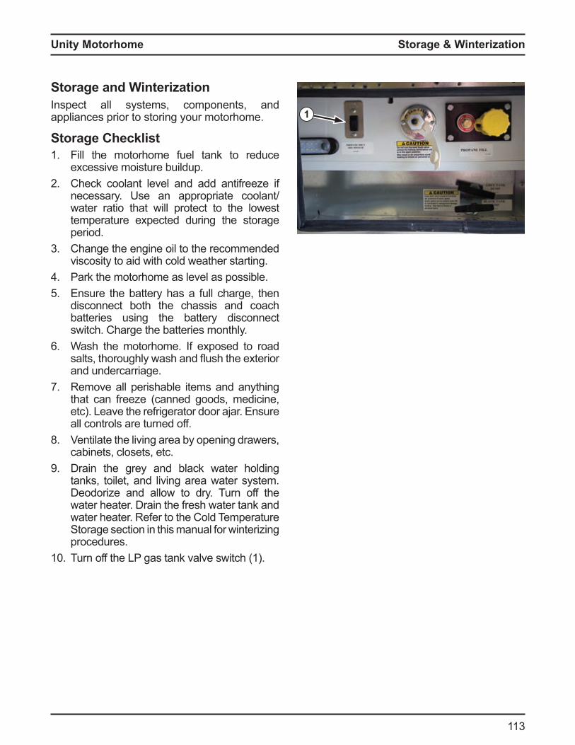
Unity Motorhome
113
Storage & Winterization
1
Storage and WinterizationInspect all systems, components, and appliances prior to storing your motorhome.
Storage Checklist1. Fill the motorhome fuel tank to reduce
excessive moisture buildup.2 Check coolant level and add antifreeze if
necessary. Use an appropriate coolant/water ratio that will protect to the lowest temperature expected during the storage period.
3 Change the engine oil to the recommended viscosity to aid with cold weather starting.
Park the motorhome as level as possible.5 Ensure the battery has a full charge, then
disconnect both the chassis and coach batteries using the battery disconnect switch. Charge the batteries monthly.
Wash the motorhome. If exposed to road salts, thoroughly wash and ush the e terior and undercarriage.
7. Remove all perishable items and anything that can freeze (canned goods, medicine, etc). Leave the refrigerator door ajar. Ensure all controls are turned off.
8. Ventilate the living area by opening drawers, cabinets, closets, etc.
9 Drain the grey and black water holding tanks, toilet, and living area water system. Deodorize and allow to dry. Turn off the water heater. Drain the fresh water tank and water heater. Refer to the Cold Temperature Storage section in this manual for winterizing procedures.
10 Turn off the LP gas tank valve switch (1).
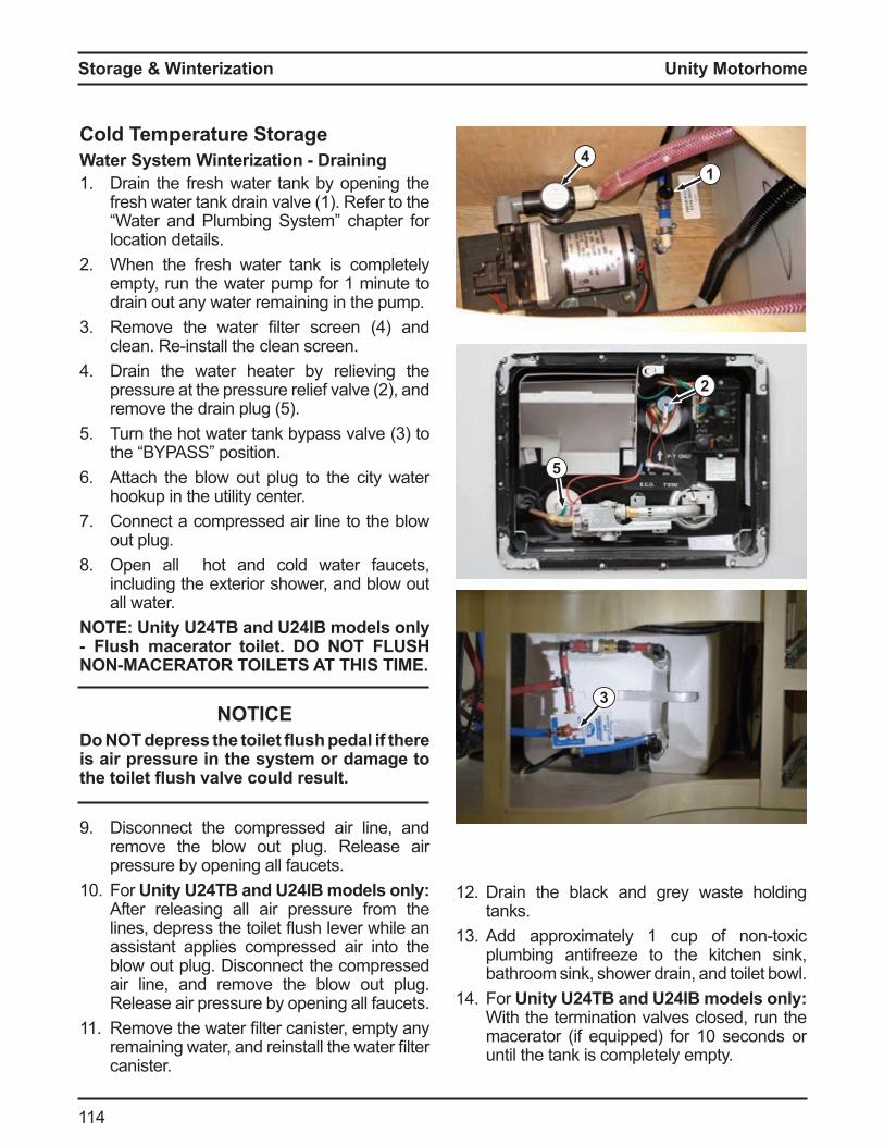
Unity Motorhome
11
Storage & Winterization
Cold Temperature StorageWater System Winterization - Draining1. Drain the fresh water tank by opening the
fresh water tank drain valve (1). Refer to the Water and Plu ing Syste chapter or
location details.2 When the fresh water tank is completely
empty, run the water pump for 1 minute to drain out any water remaining in the pump.
3 Re ove the water filter screen and clean Re install the clean screen
Drain the water heater by relieving the pressure at the pressure relie valve 2 , and re ove the drain plug 5
5 Turn the hot water tank ypass valve 3 to the P SS position
Attach the blow out plug to the city water hookup in the utility center.
7. Connect a compressed air line to the blow out plug.
8. Open all hot and cold water faucets, including the exterior shower, and blow out all water.
O nit 2 and 2 models onl lush macerator toilet. O O L S O C O O L S S .
NOTICEo O depress the toilet ush pedal if there
is air pressure in the system or damage to the toilet ush valve could result.
9 Disconnect the compressed air line, and remove the blow out plug. Release air pressure by opening all faucets.
10 For nit 2 and 2 models onl After releasing all air pressure from the lines, depress the toilet ush lever while an assistant applies compressed air into the blow out plug. Disconnect the compressed air line, and remove the blow out plug. Release air pressure by opening all faucets.
11. Re ove the water filter canister, e pty any re aining water, and reinstall the water filter canister.
3
1
5
4
12 Drain the black and grey waste holding tanks.
13 dd appro i ately 1 cup o non to ic plumbing antifreeze to the kitchen sink, bathroom sink, shower drain, and toilet bowl.
1 For nit 2 and 2 models onl With the termination valves closed, run the
acerator i e uipped or 10 seconds or until the tank is completely empty.
2
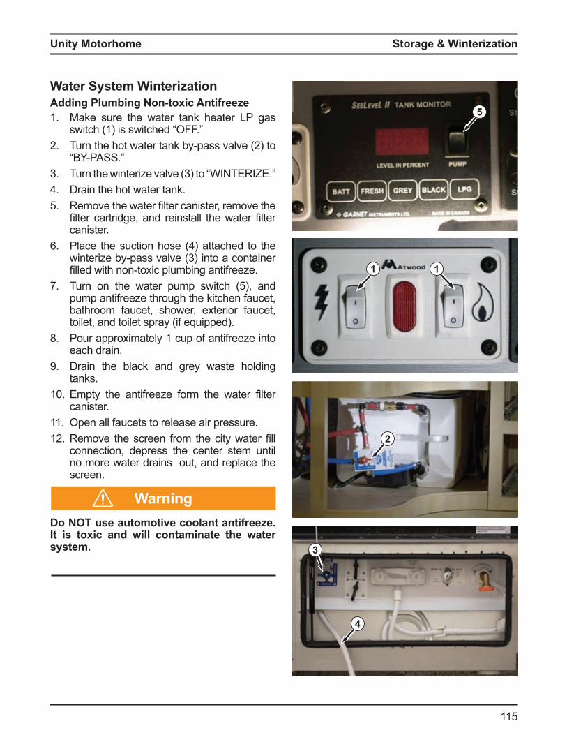
Unity Motorhome
115
Storage & Winterization
5
Water System Winterizationdding lumbing on to ic ntifreeze
1. Make sure the water tank heater LP gas switch 1 is switched
2 Turn the hot water tank y pass valve 2 to P SS
3 Turn the winteri e valve 3 to W T R Drain the hot water tank.
5 Re ove the water filter canister, re ove the filter cartridge, and reinstall the water filter canister.
Place the suction hose attached to the winteri e y pass valve 3 into a container filled with non to ic plu ing anti ree e
7. Turn on the water pu p switch 5 , and pump antifreeze through the kitchen faucet, bathroom faucet, shower, exterior faucet, toilet, and toilet spray (if equipped).
8. Pour approximately 1 cup of antifreeze into each drain.
9 Drain the black and grey waste holding tanks.
10 pty the anti ree e or the water filter canister.
11. Open all faucets to release air pressure.12 Re ove the screen ro the city water fill
connection, depress the center stem until no more water drains out, and replace the screen.
Do NOT use automotive coolant antifreeze. It is toxic and will contaminate the water system.
1
Warning
2
1
4
3
Unity Motorhome
11
Storage & Winterization
De-Winterizing the Water SystemsO lush entire water s stem before
filling the hot water tan .1. Refill the water tank with resh city water2 Turn the bypass valve, located in the utility
center, to the “NORMAL FLOW’ position.3 Turn the hot water heater bypass valve to
the “NORMAL FLOW’ position. Turn on the water pump switch located on
the system monitor panel in the cabinet above the coach door.
5 Open the water faucet furthest away from the water tank. Run the water until clear water appears, then shut off the faucet. Repeat this procedure for all remaining faucets including the shower and exterior faucets.
Open the hot water line until clear water appears.
Spring StartupAfter storing the motorhome for an extended period of time, run the water pump to pressurize the water system and check for leaks. Visually inspect the water syste or 15 inutes to ensure there are no leaks.
Clean all your appliances and have the propane line purged by a authorized dealer. Ensure everything in the motorhome is working correctly. Refer to the chassis manual in the Motorhome Information Kit for any chassis maintenance recommendations.
Cold Temperature OperationThe plumbing system in this motorhome is not designed for cold weather use. Temperatures at or below freezing will cause damage to the plumbing system.
ChassisCheck engine coolant level and add antifreeze, if required, to protect against lowest expected temperature. Change engine oil to the recommended viscosity to aid cold weather starting. Refer to the chassis manual in the Motorhome Information Kit for further recommendations.
L asUse propane for winter travelling because it will vaporize in extremely cold temperatures
0 0 C utane is not reco ended due to its high vapori ation te perature 32 0 C sing utane in cold te peratures ay
block the system and cause components to malfunction.
Waste SystemPrevent winter ree e up y adding regular non to ic R anti ree e into the toilet and kitchen drains to protect the holding tanks from ree ing e sure to add a su ficient a ount o non to ic R anti ree e to protect the total volume of the holding tanks.
o O use alcohol based antifreeze or other petroleum products.
Warning
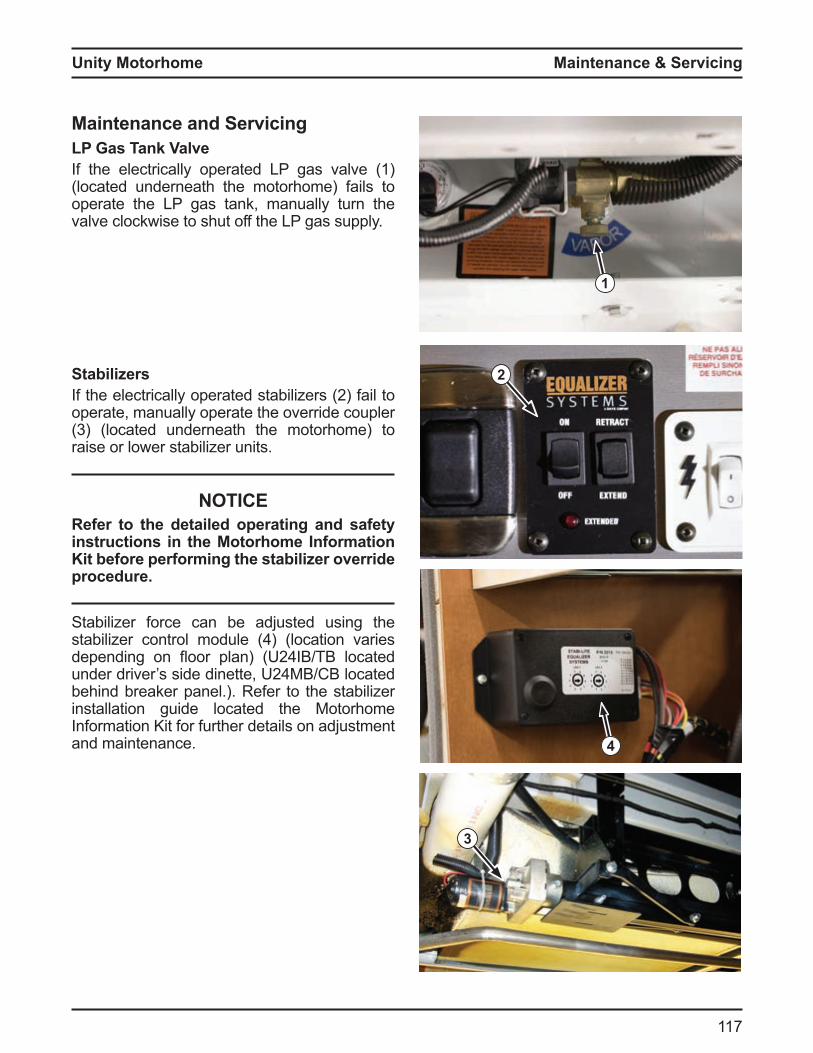
Unity Motorhome
117
Maintenance & Servicing
Maintenance and ServicingL as an ValveIf the electrically operated LP gas valve (1) (located underneath the motorhome) fails to operate the LP gas tank, manually turn the valve clockwise to shut off the LP gas supply.
Stabilizers the electrically operated sta ili ers 2 ail to
operate, manually operate the override coupler 3 located underneath the otorho e to
raise or lower stabilizer units.
NOTICERefer to the detailed operating and safety instructions in the Motorhome Information
it before performing the stabilizer override procedure.
Stabilizer force can be adjusted using the sta ili er control odule location varies depending on oor plan 2 T located under driver s side dinette, 2 C located behind breaker panel.). Refer to the stabilizer installation guide located the Motorhome Information Kit for further details on adjustment and maintenance.
2
1
3
4
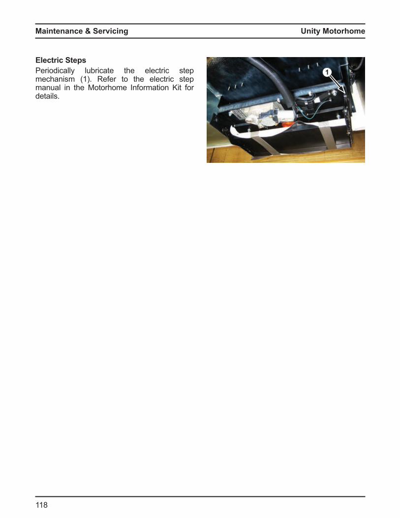
Unity Motorhome
118
Maintenance & Servicing
Electric StepsPeriodically lubricate the electric step mechanism (1). Refer to the electric step manual in the Motorhome Information Kit for details.
1

Unity Motorhome
119
Warrant olic
ew Vehicle Limited WarrantL C L .
evised ebruar 2 13
This New Vehicle Limited Warranty is the sole and only warranty applicable to your new motorhome. This Warranty is issued by Triple E Canada Ltd., only, which is the manufacturer of your motorhome. Triple E Canada Ltd., uses a variety of trade and/or division names in marketing or advertising its motorhomes. Triple E Canada Ltd., is referred to throughout this Warranty as Triple R
1. Basic Coverage. Triple R warrants to the first retail purchaser of the motorhome that all parts and components of the motorhome manufactured by Triple E RV will be free from defects in materials and workmanship or a period o twenty our onths or 2 ,000 iles 0,000 kilo eters , whichever occurs
first, a ter the date o purchase y the first retail purchaser of the motorhome from an authorized Triple E RV dealer. Defective parts shall be repaired or replaced at the election of Triple E RV upon return of the motorhome to an authorized Triple E RV service center or dealer. In addition, Triple E RV will cover the cost of labor by an authorized Triple E RV service center or dealer to remove, repair and/or replace such defective parts covered by this Warranty.
2. Structural Coverage. Triple R warrants to the first retail purchaser of the motorhome that all structural components of the motorhome manufactured by Triple E RV will be free of defects in materials and workmanship for a period o thirty si onths or 3 ,000 iles
0,000 kilo eters , whichever occurs first, a ter the date o purchase y the first retail purchaser from an authorized Triple E RV dealer. All such defective structural parts shall be repaired or replaced at the election of Triple E RV upon return to an authorized Triple E RV service center or dealer.
In addition, Triple E RV will cover the cost of labor by an authorized Triple E RV service center or dealer to remove, repair and/or replace such defective structural parts. For purposes of structural warranty coverage, structural components shall include only the main steel frame of the coach and all steel members welded to it, studs and framing in the walls of the coach, roof rafters and dela ination o the fi erglass ody parts o the coach. All other items are covered solely by and are limited by the Basic Coverage of this Warranty. On motorhomes where the chassis and coach is designed and built by another separate manufacturer, Triple E RV makes no structural coverage warranty whatsoever, and the sole and only structural warranty coverage is provided by the manufacturer of the chassis or coach.
3. Additional Warranty Terms. In the event a motorhome is used for co ercial or rental eet purposes, the Basic Coverage and Structural Coverage Warranties specified a ove shall e li ited to a period o twelve onths or 12,000
iles 20,000 kilo eters , whichever occurs first, ro the date o original purchase ll mileage warranty limitations set forth in this Warranty will be increased by that number of miles or kilometers equal to the miles or kilometers that the Motorhome was driven from its place of original manufacture to its original selling Triple E RV dealership. Although the Warranty is extended to only the first retail purchaser o the otorho e, the Warranty is transferable to the second owner of the motorhome upon written request to Triple E RV received within thirty 30 days a ter sale and trans er o title to the otorho e ro its first retail purchaser to its
second owner, accompanied by satisfactory proof of sale and transfer. Warranties for any motorhome used in an RV rental or lease eet or or a co ercial use are not transferable to any subsequent dealer, owner, eet operator or retail or consu er purchaser.
Unity Motorhome
120
Warrant olic
4. Component Warranties. Triple E RV obtains many items of equipment, appliances, components, su asse lies and or the chassis o the motorhome (referred to in this Warranty as a Co ponent ro other anu acturers Each of these manufacturers offers its own separate warranty (and in some cases warranty extension programs) covering its respective Component(s). Triple E R assigns to the first purchaser o the motorhome each and every such separate warranty with respect to a Component as the sole, exclusive and only warranty in respect of such Component. Triple E RV provides no separate or independent warranty coverage for any such Component(s). The rights of a purchaser or owner of a Triple E RV motorhome in respect of such separate Component(s) or the warranties covering such Component(s) may be conditioned upon or li ited y the specific ter s and conditions of such separate warranties . Information on separate Component warranties and registration for such warranties from Component manufacturers may be found in the Information Kit.
5. Chassis. The motorhome chassis and all components, assemblies, equipment or parts supplied or a fi ed to the chassis as received y Triple E RV from its supplier or manufacturer are Components and are covered only under separate warranties issued by the original chassis or Component manufacturer. Even i Triple R odifies the chassis in order to assemble the motorhome, the sole warranty in respect of the chassis is provided by the manufacturer of the chassis. Please contact us for details about our responsibilities for chassis odifications e ore eginning any repairs.
6. Exclusions from Warranty. The foregoing Warranty does not apply to any motorhome which has been altered outside of the Triple E RV factory in a way which in our judgment affects its stability, operation or reliability or which has been subject to misuse, negligence or accident.
The foregoing Warranty does not cover any motorhome that has been shipped to a location outside of the United States or Canada. The foregoing Warranty excludes and does not cover or provide any remedy for damage, defects or loss resulting from abuse or misuse of the motorhome or its equipment, appliances, components, su asse lies and or chassis , ailure to properly winterize the motorhome, failure to provide regular maintenance and/or service, adjustments, tune ups, alignments , road service or failure to protect the motorhome from further damage if any initial indication of damage has occurred. The Warranty excludes failure caused by overheating (regardless of cause), contamination of lu ricants, coolants, ailure o hoses, fittings, connections or lines and failure to operate and maintain the motorhome as recommended or required in the Owner’s Manual. Your Warranty may be lost, restricted or limited if your motorhome is not properly
aintained in accordance with regularlyscheduled maintenance recommendations of both Triple E RV and any manufacturers of Components, and/or the chassis of your motorhome. Your Warranty does not cover loss, defects or failures resulting from exposure to extreme conditions, including extremely cold weather. Your Warranty does not cover defects or repairs required because of improper loading, load distribution, accident, collision, vandalis , a use, isuse, neglect, fire, ood, nor al wear or i proper or inade uate
maintenance, rust or corrosion, exposure to elements or costs incurred in towing, transporting or presenting your Motorhome for repair under the Warranty. This Warranty does not cover any Component not manufactured by Triple E RV, nor does it cover sealant, tri s, a rics, oor coverings, upholstery, draperies, blinds, paint, gel coat or decals which have experienced normal pigmentation or color changes as the result of use, age, exposure to the sun or weather.
Unity Motorhome
121
Warrant olic
This Warranty excludes and does not provide coverage for consequential or incidental damages, such as the loss of your motorhome, loss of time, inconvenience, expenses , transportation to and from the dealer or manufacturing plant location, bus, taxi or air fares, telephone , travel, rental vehicle , overnight accommodations, loss or damage to your personal property, commercial loss, loss of income, loss of use or other incidental or consequential damages or expenses. The express warranties stated herein are the sole and only warranties issued by Triple E RV in respect of your Motorhome, and Triple E RV hereby expressly disclaims all other warranties, including implied warranties of
erchanta ility or warranties o fitness or any particular purpose. Neither your dealer nor any other person is authorized to create or imply any other warranty on behalf of Triple E RV beyond those expressed herein. Your warranty expressly excludes liability for incidental or consequential damages
7. Obtaining Warrant epairs. To obtain warranty repairs, you must at your own cost present your motorhome to an authorized service center or dealer during normal business hours and provide a written list of claimed defects or items to be repaired. If requested, you may be required to provide records showing that the motorhome has been maintained as required or recommended by the Owner’s Manual. As the owner, you are solely responsible for maintenance of the motorhome as required or recommended by the Owner’s Manual and associated costs of that maintenance. Repairs necessitated by failure to maintain the motorhome as required or recommended are not covered by this Warranty.

Unity Motorhome
122
Notes
Notes
LTV Roadside Assistance
4287 Beltline Road, Box #198Addison, TX 75001
for EMERGENCY ROADSIDE CALL
1•877•219•3831
Product improvement is a continuing process at Triple E Recreational Vehicles. We reserve the right to change specifications, operating instructions, standards and options on any products without
prior notice. The information, illustrations and pictures within this document are current at the time of printing.
Copyright, Triple E Canada Ltd.
P/N 146-4592 - DECEMBER 2015Printed in Canada
301 Roblin Blvd., Box 1230 Winkler, MB Canada R6W 4C4 Telephone: 204-325-4361 Fax: 204-325-5241
US Address: P.O. Box 68 Walhalla, ND 58282
www.tripleerv.com • [email protected] • www.leisurevans.com • [email protected]
Triple E Recreational Vehicles and Leisure Travel Vans are brands and trademarks of Triple E Canada Ltd.