United States Patent 5,755,571 - NASA€¦ · United States Patent 1191 [111 Patent Number:...
17
United States Patent 1191 [111 Patent Number: 5,755,571 Companion Date of Patent: May 26, 1998 DIFFERENTIAL MEASUREMENT PERIODONTAL STRUCTURES MAPPING SYSTEM Inventor: John A. Companion. Hampton. Va. Assignee: The United States of Amelia as represented by the Administrator of the National Aeronautics and Space Administration, Washington. D.C. Appl. No.: 712,984 Filed Sep. 9,1996 Int. CL6 ..................................................... A61C 19/04 U.S. C1. ................................ 43372; 128/776; 331514 Field of Search .................................. 433R2. 75, 32; 12W76.777: 331513.514 References Cited U.S. PAl'ENT DOCUMENTS 4,250,895 a1981 Lees .......................................... 433172 4,665,621 91987 Ackennan et al. ....................... 33/513 4,677,156 1/1987 Simon et al. ............................. 331514 4,708,647 11/1987 Pippin et al. ............................. 433B2 4,823,809 4/1989 Gott, Jr. et al. ........................ 128/776 4,904,184 2/1990 Murphyet al. ........................... 433I72 4,764,114 8/1988 Jeffccat et al. ........................... 433172 4,947,245 811990 Ogawa et al. ............................ 358/98 5,382,163 111995 pumam ................................... 433/215 5,100,318 3/1992 Demyun et al. .......................... 433f72 5,197,481 311993 Ackerman et al. ..................... 128/776 Primary Exarniner-Cary E. O'Connor Attomex Agent, or Firm-Robin W. Edwards [571 ABSTRACT This invention relates to a periodontal structure mapping system employing a dental handpiece containing first and second acoustic sensors for locating the Cemento-Enamel Junction (CEJ) and measuring the differentialdepth between the CEJ and the bottom of the periodontal pocket. Measure- ments are taken at multiple locations on each tooth of a patient. observed. analyzed by an optical analysis subsystem. and archived by a data storage system for subsequent study and comparison with previous and subse- quent measurements. Ultrasonic transducers for the first and second acoustic sensors are contained within the handpiece and in connection with a control computer. Pressurized water is provided for the depth measurement sensor and a linearly movable probe sensor serves as the sensor for the CEI finder. The linear movement of the CEJ sensor is obtained by a control computer actuated by the prober. In an alternate embodiment the CEI probe is an optical fibex sensor with appropriate analysis structure provided therefor. 20 Claims, 9 Drawiug Sheets https://ntrs.nasa.gov/search.jsp?R=19980203165 2020-05-03T00:49:43+00:00Z
Transcript of United States Patent 5,755,571 - NASA€¦ · United States Patent 1191 [111 Patent Number:...

United States Patent 1191 [111 Patent Number: 5,755,571 Companion Date of Patent: May 26, 1998
DIFFERENTIAL MEASUREMENT PERIODONTAL STRUCTURES MAPPING SYSTEM
Inventor: John A. Companion. Hampton. Va.
Assignee: The United States of Amelia as represented by the Administrator of the National Aeronautics and Space Administration, Washington. D.C.
Appl. No.: 712,984
Filed Sep. 9,1996
Int. CL6 ..................................................... A61C 19/04 U.S. C1. ................................ 43372; 128/776; 331514 Field of Search .................................. 433R2. 75, 32;
12W76.777: 331513.514
References Cited
U.S. PAl'ENT DOCUMENTS 4,250,895 a1981 Lees .......................................... 433172 4,665,621 91987 Ackennan et al. ....................... 33/513 4,677,156 1/1987 Simon et al. ............................. 331514 4,708,647 11/1987 Pippin et al. ............................. 433B2
4,823,809 4/1989 Gott, Jr. et al. ........................ 128/776 4,904,184 2/1990 Murphyet al. ........................... 433I72
4,764,114 8/1988 Jeffccat et al. ........................... 433172
4,947,245 811990 Ogawa et al. ............................ 358/98
5,382,163 111995 pumam ................................... 433/215
5,100,318 3/1992 Demyun et al. .......................... 433f72 5,197,481 311993 Ackerman et al. ..................... 128/776
Primary Exarniner-Cary E. O'Connor Attomex Agent, or Firm-Robin W. Edwards
[571 ABSTRACT
This invention relates to a periodontal structure mapping system employing a dental handpiece containing first and second acoustic sensors for locating the Cemento-Enamel Junction (CEJ) and measuring the differential depth between the CEJ and the bottom of the periodontal pocket. Measure- ments are taken at multiple locations on each tooth of a patient. observed. analyzed by an optical analysis subsystem. and archived by a data storage system for subsequent study and comparison with previous and subse- quent measurements. Ultrasonic transducers for the first and second acoustic sensors are contained within the handpiece and in connection with a control computer. Pressurized water is provided for the depth measurement sensor and a linearly movable probe sensor serves as the sensor for the CEI finder. The linear movement of the CEJ sensor is obtained by a control computer actuated by the prober. In an alternate embodiment the CEI probe is an optical fibex sensor with appropriate analysis structure provided therefor.
20 Claims, 9 Drawiug Sheets
https://ntrs.nasa.gov/search.jsp?R=19980203165 2020-05-03T00:49:43+00:00Z

U S . Patent May 26, 1998 Sheet 1 of 9
i-
\
27
5,755,571
10
/
7
I 'A
FIG. 1

US. Patent May 26, 1998 Sheet 2 of 9 5,755 ,57 1
C
FIG. 2

U.S. Patent May 26,1998 Sheet 3 of 9 5,755,571
FIG. 3

US. Patent May 26,1998 Sheet 4 of 9 5,755,571
a

U.S. Patent May 26,1998 Sheet 5 of 9
44
5,755,571
FIG. 5
US. Patent May 26, 1998 Sheet 6 of 9 5,755,571

U.S. Patent May 26,1998 Sheet 7 of 9 5,755,571

US. Patent May 26,1998 Sheet 8 of 9 5,755,571
- 49
FIG. aa
55
FIG. 8c
44a
FIG. 8d

U.S. Patent May 26,1998 Sheet 9 of 9 5,755,571

5.755,57 1 1
DIFFERENTIAL MEASUREMENT PERIODONTAL STRUCTURES MAPPING
SYSTEM
ORIGIN OF THE INVENTION
The invention described herein was made in the perfor- mance of work under a NASA Contract and is subject to the provisions of Section 305 of the National Aeronautics and Space Act of 1958. as amended, Public Law 85-568 (72 Stat. 435; 42 USC 2457).
mELD OF THE INVENTION This invention relates generally to measurement systems
and relates specifically to a system for differential measure ment and mapping of periodontal structures of a dental patient.
BACKGROUND OF THE INVENTION Periodontal disease is the single most pervasive dental
disease. and is the leading cause of tooth loss for adults over 35 years of age. The principal mechanisms by which peri- odontal disease causes tooth loss are erosion of the peri- odontal ligament which holds each tooth into its socket and then erosion of the actual bone of the socket so that the tooth gradually loses its supporting structure. The disease typi- d y proceeds from an increased concentration of bacteria in the normal sulcus @ocket) formed where the gingival epi- thelium folds downward along the tooth face at the abutment point. The sulcus is normally quite shallow and 1-2 mm of depth is not cause for concern. Periodontal disease can be quite localized and is not painful in the early stages. The progression of the disease can cause rapid. localized deep ening of the pocket. The pocket will later become inflamed, pus filled, and prone to bleeding when the teeth are brushed or probed by a dentist.
Since the early stages of the disease are painless. many people do not realize that they have it until it is well advanced. Many others find the current state of the. art of manual probing to be saciently uncomfortable that they put it off until the disease is well advanced Aggressive treatment is then the only option. Areliable, accurate method which would detect the disease at an early stage and also be less objectionable to the patient would be a real advance ment. In the dental research arena there are millions of dollars and hundreds of thousands of man hours presently being dedicated to developing biochemical and miaobial tests for periodontal disease activity. but there is no “gold standard” measuring technique for the accurate detection and assessment of the disease.
The space occupied by the periodontal ligament is nor- mally on the order of 0.5 mm wide and is located between the outer surface of the root of the tooth and the inner surface of the bone forming the socket in which the tooth resides. The actual periodontal ligament. which is a dense fibrous tissue, M s the periodontal space and the fibers of which it is composed penetrate pores in both the tooth and the bone surfaces to bond the tooth in place in a slightly resilient manner. The actual crest of the periodontal ligament is normally covered with approximately 1 nun of epithelial tissue which forms the bottom of the periodontal pocket. m e dental community has concluded that tracking the recession of the upper boundary of the periodontal ligament over a period of time is a good measure of the progress of peri- odontal disease.
The Fairnary accepted method for making this measure- ment in general use today is periodontal probing. In this
2 procedure, the dentist inserts the tip of a graduated metal probe at the juncture of the gingival margin with the face of an individual tooth and pushes it manually down along the root surface. When sac ien t resistance is felt, the dentist
5 judges that the periodontal ligament has been reached. the depth of insertion is measured via the tool graduations and recorded onto a printed chart. The dentist is trained to. and assumed to. push the probe into the tissue with a force of 25 grams (although some studies have found that 35 grams
io produces more accurate results). to insure consistency of the probe readings. In reality. this procedure is highly invasive. uncomfortable for the patient. and subject to a high degree of variability. The desired reference point is the Cemento- Enamel Junction (CU) which is the demarcation line
15 between the crown and the root of the tooth. If the CEI is covered by inflamed tissue or is below the gingival margin, for whatever reason. then the dentist must try to estimate the distance of the CEJ below the gingival margin to provide the reference. The gingival margin itself is not satisfactory as a
20 reference because it is not a constant. It may recede or be swollen and inflamed. Likewise. the crown of the tooth is subject to wear. accident and reconstruction and is. therefore, an unreliable reference for a measurement that must be repeated at intervals over sometimes long periods of
25 time. The taking of these measurements is complicated by a numbex of factors. The depth of the pocket must be deter- mined by feel. Measuring the pocket at only selected spots around the tooth may miss a narrow pocket completely. Frequently. the CEI must be found by feel. which depends
30 on the existence of a “step” in the surface contour at the CEJ. Given human variability, th is is probably not always going to be present. If a restoration is present that obliterates the CEI, good dental practice is to eliminate any “step“, if possible. as a potential home for bacteria. There has been an
35 automated. constant force, CEJ finder probe produced experimentally at the University of Alabama. which looks for the presence of a “step”. It then computes the provable location of the CEJ using acceleration and velocity data along the path of movement of the probe. T h i s system is as
40 invasive as a conventional probe and produces. at best. only a probable location for the CEI. There also is on the market a device known as the ‘‘Florida Probe”. This device uses a calibrated spring on a swing arm arrangement to measure the depth of penetration of a mechanical probe relative to the
45 gingival margin. The data output by the device is recorded on a computer and printed out on a preprinted chart. The device is straight-forward but s t i l l invasive and uses an unreliable reference point. There have been other attempts to build constant force probes. None of these have gained wide
SUMMARY OF THE INVENTION It is an object of the present invention to provide a
diagnostic mapping system for making and recording dif- 55 ferential measurements of periodontal structures of a dental
patient. in a minimally invasive manner. Another object of the present invention is to provide a
system for differential measurement and mapping of the upper boundary relative of the periodontal ligament of each tooth of a dental patient to a fixed point. the CEI, as an indicator of the presence of periodontal disease.
Another object of the present invention is to provide a system for measuring and mapping all periodontal smcbxes of each tooth of a dental patient that minimizes dependency
A further object of the present invention is a handpiece operable by an examining dental practitioner that contains.
so acceptance in the dental community for various reasons.
65 of manual skill to obtain accurate results.

5.755.57 1 3 4
and permits control of. active sensors for measuring and mapping periodontal structures of a dental patient.
handpiece operable by an dental connecting structure therefor, that measures and records a 5 Out
permanent record of periodontal structure measurements. A0 additional object of the present invention is a mea-
suring and mapping system for use in diagnostic periodontal
mated record keeping. Another object of the present invention is a process for ne movement of the probe is controlled by a feedback
&@tal measurement* analyzing. with control system to find the CEI. Such system are well known previous meaSWementS. video disphyblg and data Storage and can be implemented in software. The position ofthe tip of periodontal data for a dental patient. 15 is measured by a highly accurate position sensor on the
Still another object of the present invention is a process movement. A numbex of commercial system offer accwa- for differential measurement and mapping of periodontal ties that fall in the desired range. The location of the structures of a dental patient. identified CEI is returned to the movement control system.
Anothex object of the present invention is an accurate. and to the data analysis system for use as a factor in the consistent. rapid. and relatively painless. system for obtain- 2o measurement calculation. After the CEI location is trans- ing periodontal data for a dental patient. mitted to the data analysis system, the CEJ finder probe is
According to the present invention, the foregoing and Withdraw0 into its rest position. The SCanllhg ultrasound additional objects are a w e d in One aspect of the present transducer then transmits a short pulse Of sound wave at a invention by providing a handpiece for an examining dentist frequency in the range Of 15-25 MHz a Water filled. having a oriented, linear movement to identify and 25 f r u S t o - C ~ n i d extension housed within the tip of the hand- locate the Cemento-Enamel Junction (CW) of a specific piece. The function Of this extension is three-fold: The Water tooth, at the point where the enamel of the crown and the Within the eXtenSi0n Offers a 10W aCOUStiC impedance path cementum of the root of the tooth come together. and an for the ultrasound Pulse to Pass into the periodontal Pocket; ultrasonic pulse echo sc-er to -ge and masure the the shape Of the extension reshes the ultrasound beam from depth of the periodontal pocket and the level of attachment 30 a nominal 0.24 inches at the t ~ ~ s d u c e r face to aPPrOfi- of the periodontal ligament, both relative to the at the aperture; and. water forced in a stream Linear movement preferentidy carries a small, ultrasonic from the aperture of the extension floods the contact area and transducer mounted at the distal end of a thin (~0 .5 m) the PeriodOIltd pocket With Water to ensure that there are no flexible. polystyrene. probe through which it transmits and Voids Or air bubbles in the Path Of *e ultrasound beam. receives acoustic pulses to interrogate the s&ace of the 35 ~ ~ a s o u n d of th is high frequency not pass through air. tooth. The system detects differences between the material The water is continuously resupplied through a pressure composing the enamel of the aown of the tooth and the regulating connection to the standard watex supply available material composing the root of the tooth. As the movement in al l dental offices. d e s the tip of the probe across the boundary between the Because the ultrasound beam diameter is of approxi- enamel and the cementum, the abrupt change in signal 40 mately the same size as the periodontal space. it can pass characteristics produces a state change in a toggle circuit to into that space with minimal loss. Minimal loss is important indicate the transition point. The accuracy of the measure- as the actual energy content of the beam is vesy low. The ment is a function of the step size of the linear movement mataials and structures filling the periodontal space repre- driver. If the circumstance is such that the CEJ is obliterated sent an area of relatively lower acoustic impedance between at the chosen point by a restoration, crown. or other artifact, 45 the much harder materials composing the tooth and wall of the system can compare the signal characteristics of the the bony pocket. The periodontal space will act therefore, interrogated material and compare them to values stored in somewhat as an acoustic wave guide which helps the a solid state “look-up” table. The boundary of the artifact is acoustic wave foLlow the curved surface of the tooth root. then identified in the manner described above and used as The denser tissue (relative to the contents of the periodontal the reference point. The linear movement is in fixed. known. 50 pocket) of the epithelium at the bottom of the periodontal geometric relationship to a second ultrasonic traqsducer pocket, and the sti l l denser fibers of the actual periodontal operating at a frequency in the range of 15-25 MHz. This ligament located below the epithelium, will reflect echoes second, high frequency ultrasonic transducer is used to scan back to the source transducer. The geometries involved. the the periodontal pocket and the periodontal structures adja- frequency and the size of the beam act together to make the cent to, or abutting the surface of. the tooth root. The 55 bony pocket, which is not of interest for the desired scanning ultrasonic transducer is mounted within the tip of measurement, an extremely poor ultrasonic reflector in this the handpiece and communicates with the oral structures via procedure. This reduces to an absolute minimum any intru- a smal l aperture at the apex of that tip. The CET finder probe sion of the bony pocket into the field of view of the system is normally retracted into a position adjacent to the scanning of the present invention. transducer and, when extended. passes through the same 60 The speed of the acoustic wave in tissue and in water is aperture that the ultrasound scan will subsequently pass a known constant. Therefore, the distance drom the ultra- through. sound transducer to the structure of interest is simply the
To activate the system. the tip of the handpiece is placed time of flight in microseconds, times the velocity for tissue against the side of the tooth at the gingival margin. unless in mm per microseconds, divided by 2 (the time for the there has been substantial gum recession. in which case the 65 acoustic pulse to get to the structure of interest and the time tip is placed on the surface of the tooth slightly above the for the echo to return). Since the distance between the CH. After the tip of the handpiece is placed at the point of ultrasound transducer and the CEI has been derived in the
interest and the tooth identification numbex and the location point are entered via the control system. the scan is activated by the dentist practitioner. The h e a r movement then Slides the tip of the CEI detection probe from its retracted position,
Of the tooth while the C H finder ultrasound transducer emits a continuous series of interrogating pulses which travel down the flexible and into the sdace of the tooth at the probe tip. ne handpiece tip is urged ag,st the
of the CEJ detection probe.
Another object of the present invention is a combination and
the aperture and down along the
procedures that Provides moved and auto- 1o surface of the tooth by virtue of the shape, material and path
The rnately 0.5

5.755.571 5 6
previous step. the distance (or probing depth) to the struc- against the gingival margin and flooding the periodontal tures of interest is the difference between those two mea- pocket with water; surements. FIG. 5 is a schematic view similar to FIG. 4 (with parts
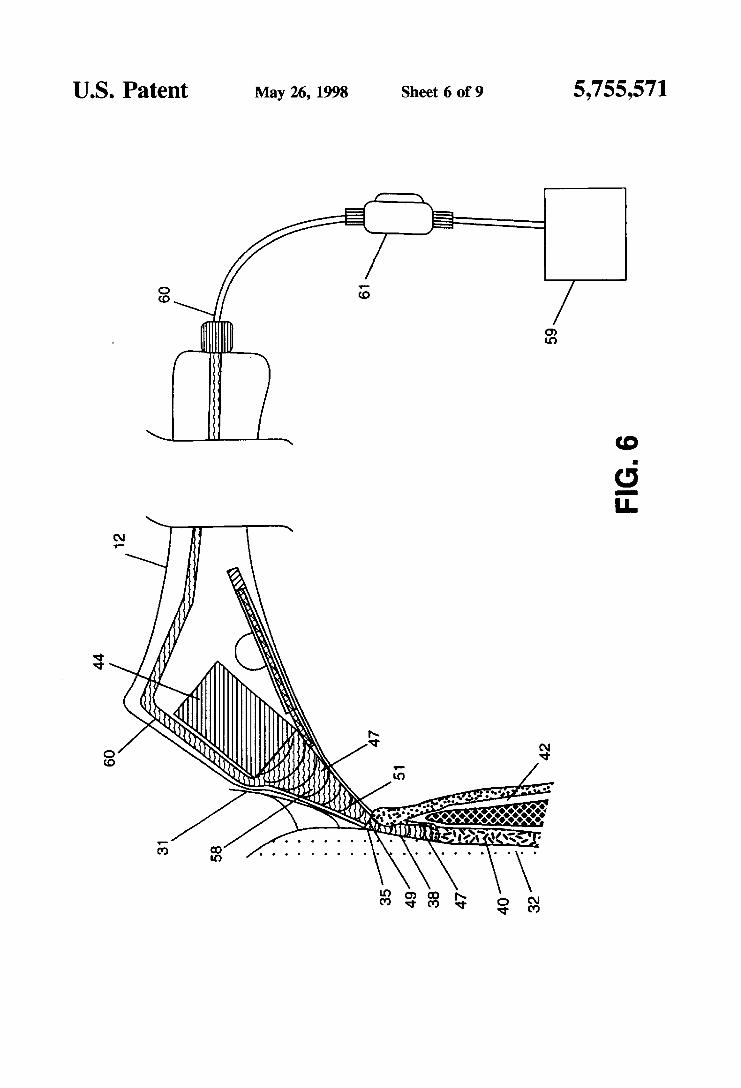
If desired, the CEJ locating operation can be repeated for omitted) and illustrating the CEJ finder probe extended into verification. The values will be displayed to the operating 5 the lumen and out of the aperture along the surface of the physician, and upon acceptance will be automatically tooth: assigned to the location on the correct tooth and recorded in FIG. 6 is a schematic view similar to FIG. 5 with the CEI the patient records. The archived patient records have the finder probe retracted and illustrating the sound pulses capability of accepting annotation at any time. including traveling from the ultrasound transducer down through the post procedure.
The signal analysis and display software will produce a FIG. 7 is a schematic view of the echoes from the bottom two-dimensional image with color coding and distance data of the pocket and the top of the periodontal ligament superimposed for the dentist to use in making the diagnosis. returning to the ultrasound transducer; Automatic archiving and retrieVd Of patient data for track- 15 and d are schematic view details of the ing and comparison purposes are also provided. movement of the CEJ finder probe out of the rest position,
After the operating physician gains some skill with the through the lumen and out of the tip aperture of the hand- use of the system, hdshe should be able to do a quick scan piece; and bY Sliding the probe tip along the gingival t a g FIG. 9 is a schematic view of part of the mapping system data Continuo~slY, without dePlOYing the finder. As long 2o of the present invention when employing a fiber optic CEI as no pocket below the nominal depth is Observed then there should be no need for further attention. If a suspicious area is located. then the full cycle can be run. This type of operation would speed up a periodontal scan dramatically, as Referring now to the drawings and more particularly to well as applying the absolute minimum of discomfort to the 25 FIG. 1. the differential measurement periodontal structures patient. These virtues would make for increased patient mapping system of the present invention is schematically acceptance of the procedure. and greata throughput of shown and designated generally by reference numeral IO. patients for the dentist. Coupled with increased accuracy Mapping system 10 includes a handpiece 12 having a sensor over time and automated record keeping, the set of system probe 14. under the control of a linear movement, extending capabilities represents a distinct improvement in the state of 3o from a first end thereof. The sensor probe 14 is linearly the art. movable relative to the housing of handpiece 12. and the
AS an alternative metho&logy for finding h e m, the details of which will be more fully described hereinafter. a finder probe can be fitted with an optical interrogation The second end of handpiece 12 is connected V h cable 16 system. The optical system operates in a completely ando- k o ~ g h a first chassis 17 to a control COW^^ 23 and an gous manner to the acoustic system, but uses Werent 35 analysis Subsystem 21- control computer 23. connected to a material properties. The material interrogation and boundary suitable Power SUPPlY (not shown). and housed in first detection can be accomplished by the use of a fiber optic chassis 17, controls the oper&iOIl for movement Of sensor pickup which would be mounted in the same as probe 14 and fOr the operation Of analysis subsystem 21. described above on the linear movement. The fiber optic power for OW&On Of Control C O W U m 23 is Provided bY pickup interrogates the material with illumination from two 4o a cm~nt iona l AC or DC power SUPP~Y. (2) laser diodes at two (2) selected frequencies. The enamel A small display 25. attached on an adjustable arm 26. of the crown reflects more energy at frequency 1 that at which can be mounted to the dental chair, or to a movable frequency 2, with the converse being true on the cementum support 260, is in operative connection with the optical of the root. The reflected laser light is detected by two (2) analysis subsystem 21. as will be further explained herein- Optical pickups which are individually selected and tuned to 45 after. A data storage system 27 is in connection with analysis frequency 1 and frequency 2. The outputs of the optical subsystem 21, as will also be M e r explained hereinafter. pickups undergo a state change at the transition point. It is Conventional foot pedal controls 28 are provided for con- possible to use a look-up table to provide sensitivity to trolling the O F a t i O n of the mapping System 10. restoration material in this scheme as well. As schematically shown in FIG. 1, the signal analysis and
50 display software will produce a two-dimensional. bar graph BRIEF DESCRlpTION OF THE DRAWINGS type image on display 25. 'Ihe bar graph will give depth in
%oth mrn increments. If the scan is of a previously scanned
delta change. Each frame has the relevant patient data as a
Changes in the differential measurements will be visible and o v ~ a time interval where periodontal disease is present, and will give an indication, and the rate of progress of the disease. Referring to FIG. 2. these changes
60 will be caused by recession of the gum tissue 36. loss of attachment of the periodontal ligament 40 and finally, ero- sion of the bony pocket that supports the tooth in the jaw bone 42. Differential measurements me n o d y obtained at three spaced intervals on the front and back of each tooth. as
Referring now more particularly to FIG. 2. there is shown an enlargement of a portion of a human tooth. designated by
lo periodontal pocket to the top of the periodontal ligament;
FIG. &1, 6,
sensor and the optical subsystem interrogator therefor.
DETAILED DESCRIPTION
A more Of the invention and the previous Scan be displayed together with the Of the attendant advantages appreciated when considered with the detailed description 55 header. and the accompanying drawings, wherein:
FIG. 1 is a schematic illustration of the periodontal mapping system of the present invention;
FIG. 2 is a Part Schematic* Part sedonal. illustration Of a n o d human tooth and periodontal structures;
FIG. 3 is a schematic view of a portion of the circled area designated "C" of FIG. 2 with the handpiece of the mapping system of the present invention in position for making measurements;
handpiece having portions shown in section to show the components contained therein. and the handpiece tip placed
will be more reaaily
FIG. 4 is a schematic view similar to FIG. 3. with the 65 well as between the teeth.
5.755.571 7
reference numeral 30. and showing a portion of the enamel surface 31 of the tooth crown. The root of tooth 30 is designated by reference numeral 32. The location of the point where the enamel 31 of the tooth crown and the cementum surface of the tooth root 32 come together is referred to as the Cemento-Enamel-Junction (CEJ) of the tooth. and is designated by reference numeral 35. The CEI for a healthy mouth. that is, one essentially free of peri- odontal disease. is normally located at. or slightly below. the top of the tooth gum 36. This gum line is termed the gingival margin of the tooth. The area or spacing between the gum (gingiva) 36 and the root 32 of a tooth 30 is called the periodontal pocket. and is designated by reference numeral 38. The bottom of periodontal pocket 38 is separated from the periodontal ligament 40 by a covering of epithelial tissue 36. which is contiguous with the inner surface of the periodontal pocket 38. The periodontal ligament 40 nor- mally covers the entire surface of the tooth root 32 and both separates the root 32 from, and attaches it to. the jaw bone 42.
Circled area ‘Y=” in RG. 2 represents the general area of an individual tooth 30 that is mapped by the present inven- tion to determine the presence of. andlor the change in the attachment level of the periodontal ligament 40 and the depth of the periodontal pocket 38 as a marker, for peri- odontal disease.
Referring now more particularly to FIG. 3. an enlarged view of the circled area “C” in FIG. 2. is illustrated. As shown therein. the Open tip 49. at the distal end. of handpiece 12 is positioned against the gingival margin. (gum line) 36 of the tooth 30 to be examined. The tooth identification number is entered, via the control system. into the data storage system 27 (FIG. 1). as is the location of the point to be probed.
Referring now more particularly to FIG. 4. the scanning ultrasound transducer 44 is shown within handpiece 12 in adjacent relationship to the linear movement 46 which drives the CEI finder probe 14. from the retracted position shown to an extended position. as wiU be further explained hereinafter. Another ultrasonic transducer 44a is carried by linear movement structure 46 to transmit ultrasonic sound waves through sensor probe 14. as will be further explained hereinafter.
Ultrasound transducer 44. is within the frequency range of 15-25 MHz and, in the preferred embodiment is a 20 MHz high frequency ultrasonic transducer. Ultrasonic transducer 44a is in the frequency range of 2-5 MHz. and preferably 5 MHz. A hollow frusto-conical extension 54 is provided extending from ultrasonic transducer 44. Extension 54 includes a base poaion 55 secured to the transmitting end of transducer 44. and an apex 56 terminating adjacent the open tip end 49 of handpiece. The lumen 58 of extension 54. and the periodontal pocket 38 are flooded with water 47. The extension lumen 58 is connected to a water source 59. available in all dental offices. to provide a constant flow of water through a suitable conduit 60. Water is continuously resupplied through a pressure regulating connection 61 disposed in conduit 60. The water flow fills extension lumen 58 and exits through the distal opening 49 of handpiece 12. Since ultrasound at these high frequencies will not pass through air. water 47 is employed to serve as a medium through which the ultrasound pulses from the ultrasound transducer 44 can travel. Water 47 also serves as a couplant between the open tip 49 of handpiece 12 and the gingival tissue 36.
The pressurized water within extension 54 offers a low impedance path for the ultrasonic pulses from transducer 44
8 to pass into the periodontal pocket 38. Also. the frusto- conical shape of extension 54 resizes the ultrasonic beam produced by transducer 44 from an approximately 0.24 inch diameter at the transducer face to approximately 0.5 mm at
5 the apex 56. Water 47 is forced as a stream from the opening 49 of handpiece 12 to flood the contact area and periodontal pocket 38 to ensure that there are no voids or air bubbles in the path of the ultrasonic beam.
If the periodontal pocket 38 is large. water 47 from the extension lumen 58 wiU fill it to provide passage for the ultrasound pulses to the bottom of the periodontal pocket 38 and. hence the periodontal ligament 40.
Referring now more particularly to FIG. 5. further details of the handpiece 12 and the sensing end 14u of the CET sensor probe 14 is illustrated. In the interest of clarity and brevity, water supply 59. conduit 60 and pressure regulator connector 61 are omitted in FIG. 5. As shown therein, sensor probe 14 is shown in position to sense the location of the CEI 35 of a specific tooth 30. The CEJ probe 14 has been advanced by the linear movement 46 out of its resting place.
20 through the extension lumen 58. out of the tip aperture 49. and along the surface of the tooth 30. towards the CEI 35. The surface passed over is continuously interrogated. Sensor probe 14 is formed of any suitable flexible material that transmits ultrasonic sound waves. In a specific embodiment
25 sensor probe 14 was formed of slightly less that 0.5 mm diameter polystyrene plastic stock Other suitable plastic or composite materials that readily transmit ultrasonic sound may be employed for t h i s purpose.
The movement of probe 14 is controlled by a feedback, 30 control system to find the CEI 35 by looking for the
difference in material Characteristics on either si& of that line of demarcation. If the area of the tooth 30 to be inspected has a restoration, the material characteristics of the restorative material are available to the control system via a
35 “look-up table” in system memory that has previously been loaded with the relevant characteristics of different types of restorative materials. The operator selects a material from a fist and the control system uses that value. looking for the crossover point to the known value for the cementum of the
40 tooth root. The position of tip 14a of probe 14 is measured by a highly accurate position sensor 5Q which is incorpo- rated into the linear movement 46. The determined. relative location of the CEI 35 is returned to the control subsystem 21 and to the data analysis and display computer 27. For the
45 desired degree of accuracy. a commercial Linear Variable Displacement Transducer is employed. or alternatively, a stepper motdencoder could be employed to drive the movement and supply a measurement output, There are several types of available commercial linear movements that
Referring now to FTG. 6. the CEJ sensor probe 14 is shown withdrawn back into the side of the lumen 45 and the ultrasonic transducer 44 is pulsing. When the CEI 35 has been located by the CEI finder 14. a trigger pulse is sent to
55 the data analysis subsystem 21. As a result of th is stimulus the ultrasonic transducer 44 transmits a pulse of sound waves at a frequency of 20 MHz into the water filled lumen 58. The produced sound wave 51 travels down through the lumen 58. out of the distal opening 49. and is coupled into
60 the gingival margin. The sound wave 5 1 continues to travel down through the periodontal space. traversing the p e d odontal pocket 38, and passing through the epithelial tissue 36 at the bottom of the pocket. Some of the sound is reflected from the epithelial tissue 36 and some will pass through and
It is to be noted that, if there has been gum recession to the point that the CEI is exposed. the tip of the handpiece 12
50 can be used for th is process.
65 be reflected from the top of the periodontal ligament 40.

5,755.571 9
must be placed slightly above CET 35 in order for the CEI finder probe 14 to perform properly. Water is forced from the opening 49 of the lumen 58 with sufficient force to flow along the tooth surface and flood the gingival margin. thus providing a path for the ultrasound pulses. This technique is common in industrial ultrasound inspection systems where it is known as a “squirter” system.
It should also be noted that the sequence can be reversed. scanning the pocket first and then finding the CET. In that sequence the tip of the handpiece 12 is moved laterally along the gingival margin of each tooth 30. pulsing continuously from ultrasonic transducer 44. until a pocket of deeper than nominal depth is detected. At that time. the CEJ finder 14 can be deployed to accurately measure the differential depth of the detected periodontal attachment loss.
Referring now to FIG. 7. the returning echoes 52 from the structures of interest are shown returning to the transducer 44 through the periodontal pocket 38 and the water filled lumen 58. As illustrated therein, the sound waves 52 that have been reflected from the structures of interest will travel back through the pocket 38 and the water filled lumen 58 of extension 54 and be detected when they arrive at the surface of the ultrasonic transducer 44.
Referring now to FIG. Su, there is shown a perspective view of the interior of the lumen 58 illustrating the face of the ultrasound scanning transducer 44. and tip 14u of the CEI finder probe 14 being shown in the retracted or rest position in the side of the frusto-conical extension 54.
FIG. 8b is a side schematic view of the structure shown in FIG. 8a and more clearly showing the CEI probe 14 in the fully retracted position.
FIG. Se is similar to FIG. 8b and shows the CEI finder probe 14 partially extended.
FIG. 8d is similar to FIG. Sc and shows the CEI finder probe 14 extended through the tip aperture 49 of handpiece 12 and extension 54.
Referring now to FIG. 9. an alternate embodiment for the CET finder probe is illustrated. In this embodiment, ultra- sonic sensor probe 14 is replaced by a fiber optic sensor probe 64. Also. ultrasonic transducer 44a is omitted. This embodiment operates in a completely analogous manner to the acoustic system, but uses different mataial properties. The fiber optic sensor probe 64 is movable, by linear movement structure 46. from a retracted position within headpiece 12 to an extended position to contact and find the CEI of a tooth.
Fiber optic probe 64 interrogates the material with illu- mination from two laser diodes at two selected frequencies. The enamel of the crown reflects more energy at a first frequency that at the second frequency. with the converse being true on the cementum of the root. The reflected laser light is detected by two optical pickups contained within an optical subsystem 67. which are individually selected and tuned to the first and second frequencies. The reflected laser light is transmitted by a fiber optic cable 66 from the sensor 64 to optical subsystem 67. The outputs of the optical pickups undergo a state change at the transition point in the optical subsystem to convert the signal to a digital mode. The digital signal is transmitted through computer control subsystem 23 to the analysis and display computer 21, as in the previously described embodiments. Look-up tables to provide sensitivity to restoration materials may also be employed with this embodiment of the invention.
It is thus seen that the present invention provides a system that eliminates. or at least minimizes. some of the sources of inaccuracies inherent in the standard procedure now
10 employed for detecting and evaluating periodontal disease. The present invention provides more and better diagnostic information to the physician, in a very user friendly manner. The accuracy. and repeatability obtained by the present
5 invention. will be improved to the point that it could provide a “gold standard” for periodontal measurements.
Although the invention has been described in reference to specific embodiments thereof. it is not so limited, and variations thereof will be readily apparent to those skilled in
10 the art in the light of the above teachings. For example. although the specific embodiments described herein are restricted to a two dimensional system the mounting of a sectored. as opposed to a simplex. ultrasound transducer as the depth scanning element would permit the formation of a
15 narrow angle sector scan. That data could then be processed to give a real time image of the periodontal area with a much richer information content. Such an image would provide the dentist practitioner with a more comprehensive picture of the actual conditions within the periodontal area and thus
20 the possibility of more accurate diagnosis in the presence of complications. The richer information content could also permit the use of the present invention as a resource for the diagnosis of other conditions. oral and otherwise.
Again. it appears possible to do direct video imaging 25 within the periodontal pocket so that the physician rnay
visually evaluate the on-site conditions from the magnified image provided on the display screen of the data analysis computer.
Thus. it is to be understood that the specific embodiments 30 described herein are to be deemed as exemplary only and are
not exhaustive. Where specific materials are mentioned. it is to be understood that these specific examples are given as illustrative purposes only and are not to be deemed as requirements. Any material having the structural and chemi-
3J cal propeaties needed to perform the intended functions are considered to be operative in practice of the present inven- tion. These. and other and various modifications and varia- tions of the invention will. accordingly. be readily apparent to those skilled in the art in the light of the above teachings. It is therefore to be understood that. withh the scope of the appended claims, the invention rnay be practiced other than as specifically desmied herein.
What is claimed as new and desired to be secured by Letters Patent of the United States is: 1. A diagnostic mapping system for making and recording
differential measurements of periodontal structures of a dental patient comprising. in combination:
a dental handpiece having a fmt and a second end and. adapted to be controllably placed by a dentist at the points of interest along the gingival margin of each tooth of a patient;
first and second acoustic sensors disposed within an open. tapered tip of said first end of said handpiece;
first and second ultrasonic transducers for said respective first and second acoustic sensors contained within said handpiece;
said first ultrasonic transducer being disposed in fixed spaced relationship with said open. tapered tip of said
said second acoustic sensor being a sensor probe and linearly movable from a retracted position completely within said handpiece to an extended position where a portion of said second acoustic sensor probe extends
a control computer in operative connection with said
45
50
55
6o handpiece;
65 from said handpiece;
second end of said handpiece;

5.755.571 11 12
means connected to said control computer to effect linear away from the patient to control the system during a movement of said second acoustic sensor; mapping procedure.
means connected to said control computer and to said 8. The diagnosticmPP*g Systemof Cl- 1 Wherein said second end of said handpiece for receiving and ana- first ultrasonic transducer Operates at a frequency in the lydng output from said first and said second acoustic 5 range Of 15-20 MHZ and said second ultrasonic transducer sensors; and is disposed at the distal end of said sensor probe and operates
at a frequency in the range of 2-5 MHz.
differential measurements of periodontal structures of a
means for receiving. displaying. and storage of the ana- lyzed for f d e r study and comparison with pre- 9.A diagnostic system for making and recording vious and subsequently obtained data.
2. The diagnostic
said coupler housing having a base end extending from said first ultrasonic transducer and an open apex end leading, and disposed adjacent. to said open tapered tip 15 of said handpiece;
a pressurized water supply in fluid communication with said coupler housing and serving to selectively flood the lumen thereof with pressurized water.
3. The diagnostic Upping system of claim 2 wherein said 2o
system of claim 1 including a 10 dental patient compri~ng. in combination: substantially frusto-conical coupler housing; a dental handpiece having a first and a second end:
said dental handpiece being controllable. and adapted to be placed. by a dentist at the points of interest along the gingival margin of each tooth of a patient:
first and second sensor means disposed within an open tapered tip of said first end of said handpiece:
at least one of said first and said second sensors including a sensor probe;
said sensor probe being linearly movable from a retracted first acoustic sensor is a depth measuring sensor for mea- position completely within said handpiece to an suring the depth of the periodontal pocket of an individual extended position for making contact with a point of tooth and the periodontal ligament distance relative to the interest on a tooth of a patient; cemento-enamel junction; and, wherein said pressurized a control computer in operative connection with said water flooding the lumen of said coupler housing extends 25 second end of said handpiece; into and N l s the periodontal pocket with a water flow of means connected to said control computer to effect linear sufficient force to provide a continuous water medium path movement of said sensor probe: for the ultrasound pulses between said first ultrasonic trans- means connected to said control computer and to said ducer and the periodontal pocket bottom. second end of said handpiece for receiving and ana-
lyzing output from said first and said second sensors; second acoustic sensor probe is a cemento-enamel-junction and finder and includes a flexible. linearly movable, probe; a means for receiving. displaying. and storage of the ana- linear mechanical movement structure. in connection with lyzed data for further study and comparison with p r e and, serving to provide reciprocating linear movement for vious and subsequently obtained data. said second acoustic sensor probe; and 10. The diagnostic mapping system of claim 9 wherein
said means connected to said control computer to effect said first and said second sensor means comprise a pair of linear movement of said second acoustic sensor includ- ultrasonic sensors and including a fust ultrasonic transducer ing a drive system connected to said control computer for said first sensor and a second ultrasonic transducer for and to said second end of said handpiece for said linear said second sensor; each of said first and said second movement structure to effect linear movement of said 40 ultrasonic transducers being contained within said hand- second sensor probe. piece.
5. The diagnostic mapping system of claim 1 wherein said 11. The diagnostic mapping system of claim 10 wherein means for receiving, displaying. and storage of the analyzed said first sensor is a depth measuring sensor for measuring data for further study and comparison includes a display the depth of the periodontal pocket of an individual tooth screen: mounting structure for said display screen including 45 and said first ultrasonic transducer for said lint sensor an adjustable arm support to permit location and positioning including a hollow. frusto-conical. coupler extension having of said display screen for view of the patient and the dental a base portion secured thereto and an apex terminating practitioner. adjacent to said open tip of said handpiece.
6. The diagnostic mapping system of claim 5 wherein said 12. 'Ihe diagnostic mapping system of claim 11 including display screen is a miniature video system connected to said 50 a source of pressurized water in fluid communication with control computer and serving to produce (1) a screen view said hollow. frusto-conical. coupler extension. of the patient identification; (2) current tooth number loca- 13. The diagnostic mapping system of claim 11 wherein tion of the tip of the handpiece during the procedure; (3) said second sensor is a cemento-enamel junction finda and current control settings; (4) current function underway; (5 ) includes a flexible, linearly movable, probe and said means a graduated, bar graph type display of the instantaneous 55 connected to said control computer to &ect linear move- pocket dept detected by the instrument: (6) cemento-enamel- ment of said sensor probe includes linear movement struc- junction location: (7) digital display of the cemento-enamel- ture to effect controlled reciprocating linear movement of junction to periodontal ligament distance. (8) aligned dupli- said flexible linearly movable probe. cate bar graph display of archived data for that patient. if 14. The diagnostic mapping system of claim 9 wherein available. together with the delta change in attachment level 60 said means for receiving. displaying, and storage of the and the time interval since acquisition of the archived data; analyzed data for further study and comparison includes a and (9) available command options which will return an display screen; mounting structure for said display screen: indicator of which option is selected. said mounting structure including an adjustable arm support
7. The diagnostic mapping system of claim 1 including for said display screen to permit location of said display foot control actuator means for said mapping system; said 65 screen in view of the patient and the dental practitioner. foot control actuator means being operable by the physician 15. The diagnostic mapping system of claim 9 wherein to thereby eliminate the requirement of the physician to look said first and said second sensors comprise a cemento-
4. The diagnostic mapping system of claim 1 wherein said 30
35

5.755.571 13
enamel-junction finder and a depth measurement sensor for measuring the depth of the periodontal pocket and the level of attachment of the periodontal ligament of the tooth being examined relative to the cemento-enamel-junction of the tooth.
16. The diagnostic mapping system of claim 15 wherein at least one of said sensor means is an optical fiber sensor.
17. The diagnostic mapping system of claim 16 including a fiber optic cable leading from said optical fiber sensor to an optical subsystem to convert the signal from said optical fiber sensor to a digital mode for transfer to said means for receiving and analyzing output from said first and said second sensors.
14 18. The diagnostic mapping system of claim 15 wherein
said second sensor comprises a thin flexible probe having an approximate 0.5 mm thickness for transmitting and receiv- ing acoustic pulses to interrogate the surface of a tooth.
19. The diagnostic mapping system of claim 15 wherein said first ultrasonic transducer for said depth measurement sensor has a frequency in the range of 15-20 MHz.
20. The diagnostic mapping system of claim 15 wherein said ultrasonic transducer for said cemento-enamel-junction finder has a frequency in the range of 2-5 MHz.
’
* * * * *

![United States Patent - OSS.Net · United States Patent [19] Farwell 11111 111111111111 111111lllillllllll11 111111111111111 11111111111iI11111iii US005363858A [11] Patent Number:](https://static.fdocuments.net/doc/165x107/603905c969795821012ab708/united-states-patent-oss-united-states-patent-19-farwell-11111-111111111111.jpg)