
United States Patent 4,688,092 - NASA · United States Patent [191 [ill Patent ... Keith L....
12
United States Patent [191 [ill Patent Number: 4,688,092 Kamel et al. [45] Date of Patent: Aug. 18, 1987 [54] SATELLITE CAMERA IMAGE NAVIGATION [75] Inventors: Ahmed A. Kamel, Sunnyvale; Donald W. Graul, San Mateo; John Savides, Los Altos Hills; Charles W. Hanson, Mountain View, all of Calif. Corporation, Detroit, Mich. [73] Assignee: Ford Aerospace & Communications [21] Appl. No.: 860,142 [22] Filed: May 6, 1986 [51] [52] [58] 1561 References Cited Int. Cl.4 ............................................... H06N 7/01 US. C1. ...................................... 358/109; 33/320; 358/103; 358/107; 358/140; 358/160; 382/45 Field of Search ............... 358/109, 103, 107, 140, 358/160, 180; 370/104; 382/45; 33/320 . U.S. PATENT DOCUMENTS 3,223,777 12/1965 Crawford et al. .................. 358/109 3,676,581 7/1972 Swet 3,716,669 2/1973 Watanabe 3,859,460 1/1975 Westell .................. 3,952,151 4/1976 Jenkin ....................... 4,012,018 3/1977 Lorel 4,300,159 11/1981 4,593,317 6/1986 Heydlau 4,602,375 7/1986 Inukai 4,630,111 12/1986 Blain . 4,639,774 1/1987 Fried 3,769,710 11/1973 Reister ......... .............. 33/320 Hummer et al. .................... 358/109 4,439,788 31 ’ 1984 Frame ................. 358/109 OTHER PUBLICATIONS D. W. Graul, Oral Presentation Accompanied by a Posterboard Display Before the Environmental Re- search Institute of Michigan at its International Sympo- sium on Remote Sensing of the Environment, Oct. 21, 1985. “New GOES to Sharpen Severe Weather Tracking”, Aviation Week and Space Technology, Dec. 23, 1985. A. Schwalb, “Envirosat-2000 Report; GOES-Next Overview”, National Oceanic and Atmospheric Ad- ministration, Sep. 1985, pp. 25, 26, 28, 32, 35, 36. P. D. Landecker, “Operational Spacecraft Attitude Determination Using Data from a Spinning Sensor”, Journal of Astronautical Sciences, vol. 32, No. 2, Apr- .-Jun. 1984, pp. 189-198. Primary’Examiner-Howard W. Britton Attorney, Agent, or Firm-Edward J. Radlo; Keith L. Zerschling ABSTRACT 1571 . Pixels within a satellite camera (1,2) image are precisely located in terms of latitude and longitude on a celestial body, such as the earth, being imaged. A computer (60) on the earth generates models (40, 50) of the satellite’s orbit and attitude, respectively. The orbit model (40) is generated from measurements of stars and landmarks taken by the camera (1,2),.and by range data. The orbit model (40) is an expression of the satellite’s latitude and longitude at the subsatellite point, and of the altitude of the satellite, as a function of time, using as coefficients (K) the six Keplerian elements at epoch. The attitude model (50) is based upon star measurements taken by each camera (1, 2). The attitude model (50) is a set of expressions for the deviations in a set of mutually or- thogonal reference optical axes (x, y, z) as a function of time, for each camera (1,2). Measured data is fit into the models (40, 50) using a walking least squares fit algo- rithm. A transformation computer (66) transforms pixel coordinates as telemetered by the camera (1, 2) into earth latitude and longitude coordinates, using the orbit and attitude models (40, 50). 10 Claims, 6 Drawing Figures I ORBIT I I I ORBIT I I ORBITIATTITUDE TRANSFORMATION - MODEL - - - 40 - - - I I COEFFICIENTS K,A COMPUTER 66 ATTITUDE I I -MODEL 50 I I I I L _-__ - - - - ________ _______--_--- OPERATIONS GROUND EQUIPMENT 65 IMAGE NAVIGATION SYSTEM FUNCTIONAL BLOCK DIAGRAM \ I- USER ! MODULE 70 https://ntrs.nasa.gov/search.jsp?R=20080004703 2018-08-19T02:44:37+00:00Z
Transcript of United States Patent 4,688,092 - NASA · United States Patent [191 [ill Patent ... Keith L....

United States Patent [191 [ i l l Patent Number: 4,688,092 Kamel et al. [45] Date of Patent: Aug. 18, 1987
[54] SATELLITE CAMERA IMAGE NAVIGATION
[75] Inventors: Ahmed A. Kamel, Sunnyvale; Donald W. Graul, San Mateo; John Savides, Los Altos Hills; Charles W. Hanson, Mountain View, all of Calif.
Corporation, Detroit, Mich. [73] Assignee: Ford Aerospace & Communications
[21] Appl. No.: 860,142
[22] Filed: May 6, 1986
[51] [52]
[58]
1561 References Cited
Int. Cl.4 ............................................... H06N 7/01 US. C1. ...................................... 358/109; 33/320;
358/103; 358/107; 358/140; 358/160; 382/45 Field of Search ............... 358/109, 103, 107, 140,
358/160, 180; 370/104; 382/45; 33/320
. U.S. PATENT DOCUMENTS 3,223,777 12/1965 Crawford et al. .................. 358/109 3,676,581 7/1972 Swet 3,716,669 2/1973 Watanabe
3,859,460 1/1975 Westell .................. 3,952,151 4/1976 Jenkin ....................... 4,012,018 3/1977 Lorel 4,300,159 11/1981
4,593,317 6/1986 Heydlau 4,602,375 7/1986 Inukai 4,630,111 12/1986 Blain . 4,639,774 1/1987 Fried
3,769,710 11/1973 Reister ......... .............. 33/320
Hummer et al. .................... 358/109 4,439,788 31’1984 Frame ................. 358/109
OTHER PUBLICATIONS D. W. Graul, Oral Presentation Accompanied by a Posterboard Display Before the Environmental Re- search Institute of Michigan at its International Sympo- sium on Remote Sensing of the Environment, Oct. 21, 1985.
“New GOES to Sharpen Severe Weather Tracking”, Aviation Week and Space Technology, Dec. 23, 1985. A. Schwalb, “Envirosat-2000 Report; GOES-Next Overview”, National Oceanic and Atmospheric Ad- ministration, Sep. 1985, pp. 25, 26, 28, 32, 35, 36. P. D. Landecker, “Operational Spacecraft Attitude Determination Using Data from a Spinning Sensor”, Journal of Astronautical Sciences, vol. 32, No. 2, Apr- .-Jun. 1984, pp. 189-198.
Primary’Examiner-Howard W. Britton Attorney, Agent, or Firm-Edward J. Radlo; Keith L. Zerschling
ABSTRACT 1571 . Pixels within a satellite camera (1,2) image are precisely located in terms of latitude and longitude on a celestial body, such as the earth, being imaged. A computer (60) on the earth generates models (40, 50) of the satellite’s orbit and attitude, respectively. The orbit model (40) is generated from measurements of stars and landmarks taken by the camera (1,2),.and by range data. The orbit model (40) is an expression of the satellite’s latitude and longitude at the subsatellite point, and of the altitude of the satellite, as a function of time, using as coefficients (K) the six Keplerian elements at epoch. The attitude model (50) is based upon star measurements taken by each camera (1, 2). The attitude model (50) is a set of expressions for the deviations in a set of mutually or- thogonal reference optical axes (x, y, z) as a function of time, for each camera (1,2). Measured data is fit into the models (40, 50) using a walking least squares fit algo- rithm. A transformation computer (66) transforms pixel coordinates as telemetered by the camera (1, 2) into earth latitude and longitude coordinates, using the orbit and attitude models (40, 50).
10 Claims, 6 Drawing Figures
I ORBIT I I
I ORBIT I I ORBITIATTITUDE TRANSFORMATION - MODEL - - - 40 - - - I I COEFFICIENTS K,A COMPUTER 66 ATTITUDE I I -MODEL 50 I
I I I L _ - _ _ - - - - _ _ _ _ _ _ _ _ _ _ _ _ _ _ _ - - _ - - - OPERATIONS GROUND EQUIPMENT 65
I M A G E NAVIGATION SYSTEM FUNCTIONAL BLOCK DIAGRAM
\
I- USER ! MODULE 70
https://ntrs.nasa.gov/search.jsp?R=20080004703 2018-08-19T02:44:37+00:00Z
U.S. Patent A U ~ is, 1987 Sheet 1 of 5 4,688,092
.--L
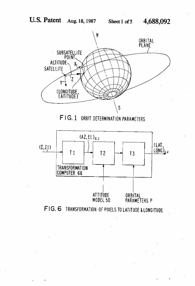
F I G. 1 ORBIT DETERMINATION PARAMETERS
(LAT., L0$3G.),
4 T 1 T 2 T 3 (I J1) L
TR A N SFO R MAT IO N :OMPUTER 66
A L
F I G. 6 TRANSFORMATION OF PIXELS TO LATITUDE & LONGITUDE

U.S. Patent AU& 18,1987 Sheet 2 of 5 4,688,092
I

U.S. Patent A U ~ 18,1987 Sheet 3 of 5 4,688,092 r - - - - - - - - - - - I r-;--- in I
I
I - - - - - - - - - -
I
-a
\ Q \ I
I
1
-1 I I I I I I I I I
- ' L L ' I
L

U.S. Patent A U ~ is, 1987 Sheet 4 of 5 4,688,092
m a z W z 4
- a
m CL 4 c m
U.S. Patent A U ~ 18,1987
r - - - - - - - - - - - -
Sheet 5 of 5 4,688,092
I\ -'-yTs- - -,
I I
OBSERVED
I
CALCULATED I MEASURE MEN TS I
I WALK I NG - L E A S T - 1 MEASUREMENTS) I I
I MEASUREMENT9 I RES1 DUALS
SQUARES ALGORITHM F I T I I
4,68 8,092 1
SATELLITE CAMERA IMAGE NAVIGATION
STATEMENT OF GOVERNMENTAL INTEREST The invention described herein was made in the per-
formance of work under NASA contract no. NAS5- 29500 and is subject to the provisions of $305 of the National Aeronautics and Space Act of 1958 (72 Stat. 435; 42 USC 2457).
TECHNICAL FIELD
This invention pertains to the field of locating each pixel within a satellite camera image in terms of earth latitude and longitude.
BACKGROUND ART
The following three items give a general description of portions of the invention:
(1) D.W. Graul (one of the instant inventors), oral presentation accompanied by a posterboard display before the Environmental Research Institute of Michi- gan at its International Symposium on Remote Sensing of the Environment, Oct. 21, 1985; (2) “New GOES to Sharpen Severe Weather Tracking”, Aviation Week and Space Technology, Dec. 23, 1985; and (3) A. Schwalb, “Envirosat-2000 Report; GOES-Next Overview”, Na- tional Oceanic and Atmospheric Administration, Sep- tember, 1985 (pages 25, 26, 28, 32, 35, 36).
P.D. Landecker, “Operational Spacecraft Attitude Determination Using Data from a Spinning Sensor”, Journal of Astronautical Sciences, Vol. 32, No. 2, April-June 1984, pp. 189-198, discusses attitude deter- mination of a spin stabilized satellite using star sensing.
Secondary references are US. Pat. Nos. 3,223,777; 3,676,581; 3,716,669; 3,769,710; 3,859,460; 3,952,151; 4,012,018; and 4,300,159.
DISCLOSURE O F INVENTION
The present invention comprises apparatus for achieving navigation of images taken by a camera (1,2) on board a satellite. The satellite is orbiting the earth or other celestial body, and generates images of scenes on the body. Each image is divided into a plurality of pix- els.
The camera (1, 2) takes and forwards measurements to modeling means (60), which generates in response thereto estimates (40, 50) of the satellite’s orbit and attitude, respectively. Using information provided by the modeling means (60), transforming means (66) trans- forms pixel locations as determined by the camera (1,2) into latitude and longitude with respect to the celestial body.
BRIEF DESCRIPTION OF THE DRAWINGS These and other more detailed and specific objects
and features of the present invention are more fully disclosed in the following specification, reference being had to the accompanying drawings, in which:
FIG. 1 is a sketch of the earth showing some of the orbital parameters used in describing the present inven- tion;
FIG. 2 is an elevational view of a GOES IJKLM satellite, a satellite which can advantageously employ the present invention;
FIG. 4 is a chart showing suitable frequencies for ranging, landmark, and star measurements used in the present invention;
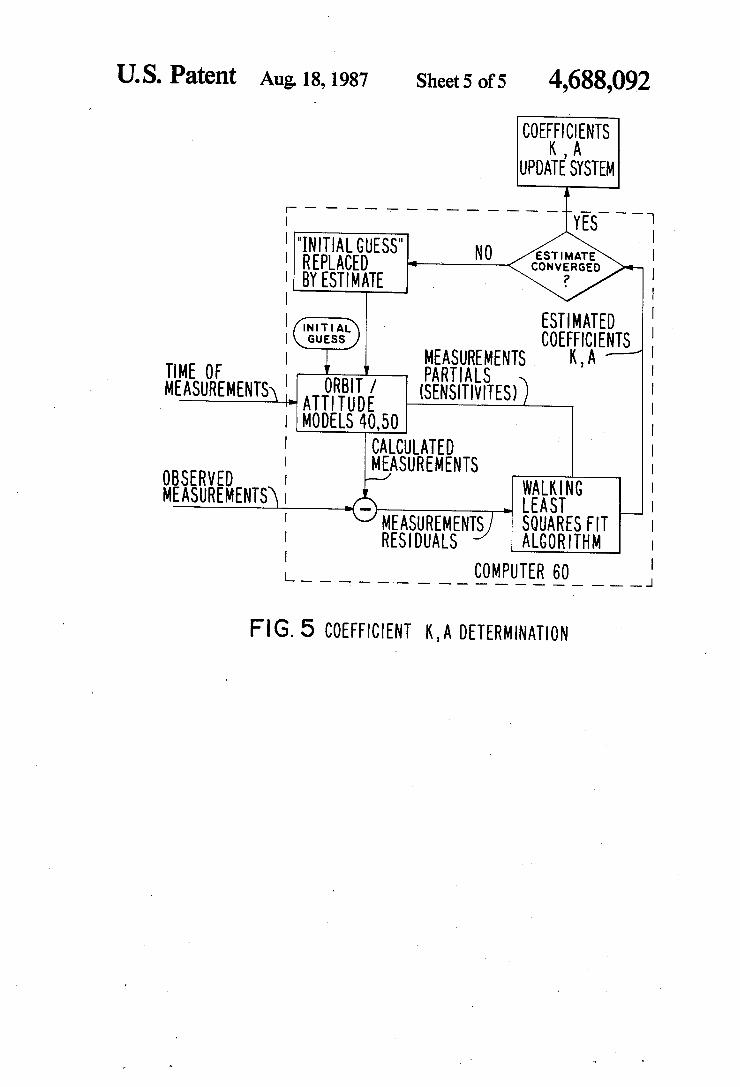
FIG. 5 is a functional block diagram showing how 5 the walking least squares fit algorithm is used to gener-
ate orbital and attitude coefficients K, A; and FIG. 6 is a functional block diagram showing the
transformations (TI, T2, T3) performed by transforma- tion computer 66.
BEST MODE FOR CARRYING OUT THE INVENTION
Although the present invention has utility on any type of satellite, it will be particularly illustrated with
15 respect to the satellite shown in FIG. 2: one of the three-axis stabilized geosynchronous GOES IJKLM meteorological satellites sponsored by NOAA (Na- tional Oceanic and Atmospheric Administration) and contracted for by NASA (National Aeronautics and
20 Space Administration). The items shown on FIG. 2 include solar array 11, X-ray sensor 12, magnetometor 13, S-band transmit antenna 14, search and rescue an- tenna 15, UHF antenna 16, telemetry and command antenna 18, earth sensors 19, S-band receive antenna 20,
25 solar sail 24, and two cameras: imager 1 and sounder 2. Imager 1 comprises cooler 17, aperture 23, and mirror 33. Sounder 2 comprises cooler 21, aperture 22, and mirror 32.
The mirrors 33, 32 are each mounted on a two-axis 30 gimbal which selectively positions the mirror 33, 32
with respect to orthogonal x and y axes at a very fast step-scan rate of many successive positions per second. The ostensibly common x axis can also be referred to as the roll, northhouth, or elevation axis. The y axis for
35 each mirror 33, 32 can also be referred to as the pitch, east/west, or azimuth axis.
Imager 1 provides multispectral radiometric imaging of the earth’s surface, which can be useful, for example, in measuring transverse cloud velocity. Imager 1 has
40 five channels, four infrared and one visible; its two-axis gimbaled scanning mirror 33 sweeps an eight kilometer longitudinal swath along an east/west path on the earth, providing co-registered data of the viewed scene from all channels simultaneously. Position and size of the area
45 scanned are controlled by command. The field of view of imager 1 is divided into a set of parallel scan lines each comprising many pixels. The pixel size (on the earth) is as small as 1 km by 1 km for one of the chan- nels. A scan frame (comprising many scan lines) is that
50 subset of the total possible field of view that is com- manded to be scanned. The scan frame is scanned in 22 minutes for a whole earth scan, less for an area scan (portion of the earth). Passive radiation cooler 17 allows operation at lower temperature for increased sensitivity.
55 Radiometric calibration is provided by periodic mirror 33 slews to space and to an internal blackbody target.
Sounder 2 measures moisture content and temperture within the earth’s atmosphere on a pixel-by-pixel basis. Sounder 2 comprises a 19 channel (18 infrared and 1
60 visible) discrete filter wheel radiometer; its two-axis gimbaled scanning mirror 32 step-scans a 40 kilometer longitudinal swath across an east/west path in 10 kilo- meter increments. The nominal pixel size (on the earth) is 10 km by 10 km. A scan frame (comprising many scan
65 lines) is scanned in an amount of time known as the correlation time. Passive radiation cooler 21 controls
lo
FIG. 3 is a functional block diagram of the major the filter wheel assembly temperature. This allows op- eration at lower temperature for increased sensitivity. components of the present invention;
-

4,688,092 3 4
Radiometric calibration is provided by periodic mirror the reference orbital axes X, Y , 2, all with respect to 32 slews to space and to an internal blackbody target. time.
Imager 1 and sounder 2 operate independently and The three components of orbital position (latitude, simultaneously over a period of time known as an imag- longitude, altitude) are known as orbital parameters P ing or sounding “interval”. The interval is specified to 5 and are determined by imager 1 star and landmark mea- be at least 85 minutes and can be as much as 12 hours. surement, and range measurements using operations During an interval, several frames are scanned and ground equipment (OGE) 65. The three components of several images made. At the end of the interval, the the imager attitude x;, y;, z; are determined by imager 1 spacecraft may enter the housekeeping mode, e.g., to star measurements. A separate star measurement by fire thrusters for purposes of attitude control or momen- 10 sounder 2 determines the long term roll, pitch, and Yaw tum dumping. angles of the sounder 2 reference optical axes x3, ys, z,.
The image navigation system described herein locates The present invention compensates for misalign- individual imager 1 and sounder 2 pixels within 1.7 km ments, drift, aging, and any other long-term attitude (36) at the subsatellite point, and within 5.0 km (36) at a variations without individual measurements Of these 60” central earth angle. This pixel location accuracy is a 15 effects, and is relatively insensitive to the magnitude Of factor of 3 and 6 better than requirements for the imager these effects. 1 and sounder 2, respectively, of the illustrated GOES The angle between star and h d m a r k is affected only 1 JKLM satellite. This accuracy is made possible be- by changes in the Spacecraft’s orbital position. Varia- cause: tions in attitude do not cause any change. Therefore, the
Each instrument 1, 2 is capable of utilizing a visible 2o orbit data is effectively decoupled from the attitude detector array to sense fourth magnitude stars. data, and orbital model 40 and attitude model 50 can be
Only range data (altitude) combined with star and determined landmark observation data (angles) are used to generate a sequence Of at the orbit model 40. once the orbit is modeled, only stai 25 least two Star measurements leads to determination of data (angles) are used to generate the attitude model 50. the attitude coefficients A.
The star and landmark data are taken through the In actual mission operation, a slight degree of cou- instruments 1, 2 themselves; therefore, all long-term pling between attitude and orbit data will occur because perturbation effects are out,99 i.e., the effect is of the small attitude change during the brief time (typi- the Same for each pixel in the earth image as it is in the cally about half an hour) between star measurements.
30 This coupling can be compensated for by combining the star or landmark image. If a separate star tracker were orbit and attitude determination process into a single used, its pointing position would not be identical to that large orbital/attitude model 40, 50. This model 40, 50 of the instruments 1, 2, due to satellite mounting mis- can then have its coefficients K, A solved for simulta- alignments and variations caused by satellite thermal neously, using, e.g., a known recursive filter or an algo- structural distortion in orbit. Star and landmark measurements do not interfere Orbital model 40 gives the orbital parameters P (satel-
Star measurement is facilitated when using a three- ellite point) as a slowly moving function of time. The axis stabilized satellite such as the GOES IJKLM illus- coefficients in orbital model 4o are the six Keplerian trated herein, because of the quiet kinematic environ- 40 elements at epoch, 6GEpoch,, is the beginning of the orbit and attitude variation that is being modeled. ment of such a satellite.
Orbit determination is the process of determining the The six Keplerian elements are the semi-major axis, satellite’s altitude, longitude, and latitude as a function eccentricity, inclination, argument at perigee, right of time. Longitude and latitude are measured at the ascension of the ascending node, and mean anomaly. subsatellite point, i.e., the point where the 2 axis inter- 45 Orbit model 4o is based on NASA or other models of
connects the center of mass of the satellite with the acceleration can include perturbing effects due to the center of mass of the earth. The 2 axis lies in the orbital asphericity of the geogravitational field up to twelfth
mass of the satellite and is orthogonal to the orbital 50 and moon, and direct solar radiation pressure on the
and 2 axes. The X axis lies along the transverse compo- Lerch et al, “Gravity Model I~~~~~~~~~~ using G~~~ nent of the satellite’s velocity vector. The X axis would 3 (GEM 9 and GEM io),?, J, ~ ~ ~ ~ h ~ ~ ~ ~ ~ ~ ~ ~ ~ ~ ~ ~ ~ h , vel. lie alopg the satellite’s velocity vector if the orbit were 84, ~~l~ 1979, pp. 3897-3916. perfectly circular. However, even for a satellite in geo- 55 synchronous orbit, the orbit is not precisely circular. into orbit determination 40 through precession, nutam
Attitude determination is the process of determining tion, and polar wander. precession and nutation are the orientation (roll, pitch, and Yaw deviations) of a set deterministic and are accounted for to 0.01 arcsecond in of mutually orthogonal reference optical axes (X, Y, 2) computer 60. Polar wander, on the other hand, is not (x* y* z)* The 60 completely predictable, but the magnitude of the effect reference optical axes x, y, z are taken with respect to (15 meters) is small enough to be ignored. fixed portions of each of imager 1 and sounder 2, corre-
mands) of their respective mirrors 33, 32. If no attitude errors exist, the x, y, z axes coincide with the X, Y , 2 65 ple: axes. Determination of the attitude model 50 requires
gles of the reference optical axes x, y, z with respect to
Once Orbit 40 is
35 rithm known as the “walking least squares fit”.
with the Operational imaging and sounding missions‘ lite altitude, and its latitude and longitude at the subsat-
sects the earth’s surface* (See l)* The (Yaw) axis total acceleration on the satellite, The modeled total
plane. The
plane. The
(pitch) axis passes through the center Of order harmonics, gravitational attractions of the sun
satellite surface. A suitable orbit model is described in axis is Orthogonal to each Of the
The motion of the earth’s spin axis introduces
to the reference Orbital
Attitude model 50 gives the movement of the x, y,
trigonometric (harmonic) function of time. F~~ exam- SPonding to null Positions (as defined by earth corn- axes for each of the instruments 1 , 2 as a slowly moving
computation of the long-term roll, pitch, and yaw an- x,=A,=A~sinwr+A~cosw/+A3sin2wr+Aqcos2wt
4.688,092 5
wt represents the angular position of the apparent daily motion of the sun about the satellite, where w is the angular velocity of the sun’s apparent motion about the satellite and t is time. This expression includes terms up to the second harmonic, which is adequate for the illus- trated embodiment. However, fewer or more harmonic terms could be inserted into the model, depending upon the desired degree of accuracy. Constant terms Ao, if present, represent fixed mechanical alignment biases. Amplitudes of the harmonics (given by the coefficients A1 through A4) represent daily variations due to solar radiation pressure effects on yaw, structural thermal distortions, and earth sensor 19 thermal drift. All these perturbations are periodic- and result from the sun’s apparent daily motion about the satellite. A harmonic series is used for model 50 because these perturbations are periodic. The trigonometric model is simple and is based on physical reality. The sources of daily variation are not determined separately; rather, their collective effects are characterized by the coefficients A. The coefficients A vary from day to day, representing sea- sonal changes in the yaw, thermal distortion, and earth sensor 19 drift, due to changes in sun declination.
The number of coefficients A of the illustrated har- monic series is five for each attitude component (x, y, z) of each of imager 1 and sounder 2, for a total of 30 coefficients. Coefficients A can be obtained together with, or independently from, the six orbital elements at epoch (K), and continuously updated afterwards. Anal- ysis shows that the accuracy of model 50 is about & 18 microradians (3 sigma) in either E-W or N-S directions.
Attitude model 50 is also used in case of satellite position change. The arguments of the trigonometric series in model 50 are expressed in terms of the sun right ascension relative to the satellite. The model is therefore independent of the satellite longitude. A separate model is not required during the drift phase between opera- tional positions.
At certain times (e.g., within the first 2 hours after eclipse or stationkeeping), the trigonometric series model 50 does not represent the actual satellite attitude behavior, due to different thermal effects. In this case, secondary attitude models are used for attitude determi- nation. Following stationkeeping, the secondary model comprises a quadratic series in time. Following eclipse, the secondary model comprises an exponential function.
FIG. 3 shows the orbit/attitude determination mea- surement processing.
Image Drocessing comwter 62 within OGE (opera-
6 50. Coefficients A and K are updated on the basis of this comparison.
The walking least squares fit algorithm used by com- puter 60 is described in FIG. 5. This provides continu-
5 ous end-to-end-calibration of the image navigation sys- tem, and self-compensation of aging, thermal effects, and all other long-term effects. The illustrated walking least-squares fitting needs to be done but weekly to update the orbital coefficients K, and every half hour to
10 update the attitude coefficients A. Coefficients A can be fitted separately and independently from coefficients K, or, alternatively, both sets of coefficients A, K can be fitted together.
The measurements sent by computer 62 and PM 63 to 15 computer 60 include pixel coordinates of the stars and
landmarks, plus range data, plus the times these mea- surements were taken. An initial guess of the coeffici- ents K and A is used for initialization of models 40, 50, based upon ranging data obtained during the transfer
20 orbit. Based upon this initial guess, models 40, 50 are solved for the “measurements”, i.e., the orbital parame- ters P and the positions of the x, y, z reference optical axes for each of imager 1 and sounder 2. These calcu- lated measurements are compared with the observed
25 measurements as provided by computer 62 and PM 63. The differences between the calculated and observed. measurements, known as “measurement residuals”, are subject to a walking least squares fit algorithm, which also uses as an input the partial derivatives of the calcu-
30 lated measurements with respect to the coefficients K, A. The result is a set of estimated coefficients K, A.
If the last preselected several of these sets of esti- mated coefficients K, A have been converging, the process is considered to have been successful, and these
35 estimated coefficients K, A become the coefficients K, A outputted by computer 60 to star acquisition com- puter 64, product transmit unit 39, and transformation computer 66. If, on the other hand, the estimated coeffi- cients K, A have not been converging, another iteration
40 of the walking least squares fit algorithm is entered into, by means of the initial guess of coefficients K, A being replaced by the latest iteration of the estimated coeffici- ents K, A.
Coefficients K, A are incorporated in the documenta- 45 tion of the imaging and sounding data that are sent to
the user modules 70, via product transmit unit 39, uplink 71, and one processed data link 72 for each user module 70. Uplink 71 and each processed data link 72 also con- tain earth latitude and longitude coordinates of prese-
tions &;nd equipment) 65 receives over downlink 69 50 lected image pixels of imager 1, and earth latitude and the raw images from the cameras 1,2. These raw images longitude of all pixels of sounder 2. Links 71 and 72 also include normal operations images, landmark images contain the locations of the first pixel in each imager 1 from imager 1, and star images from both instruments 1, scan line; and grid points for given ground locations, 2. Computer 62 processes the normal operations images given as pixel numbers, so that political boundary maps for retransmission to one or more earth-based user mod- 55 can be superimposed on the images displayed on user ules 70 via product transmit unit 39, uplink 71, and displays 67. Displays 67 may be hard copies, images on downlink(s) 72. Landmark data are processed offline CRT’s sent for distribution via commercial television using product monitor (PM) 63 and disks, to generate stations, etc. landmark pixel coordinates, and are inputted to orbit- As illustrated in FIG. 6, transformation computer 66 /attitude determination computer 60 by PM 63 as they 60 within OGE 65 receives coordinates of each scan line become available. Star sightings are processed online by (I) and first pixel (Jl) within each scan line from com- computer 62 (to generate star pixel coordinates) and puter 62. Computer 66 subjects these I, J1 pixel coordi- inputted to computer 60 in real time. nates to three transformations: Ti, T2, and T3. Ti trans-
Ranging data is processed off line by PM 63. The forms I, J1 to an AZ, EL for each pixel (angular posi- processed ranging data are inputted to computer 60 by 65 tion of the corresponding mirror 33, 32 with respect to PM 63 as they become available. its y and x axes, respectively) based on the known scan-
Computer 60 compares the star, landmark, and range ning rate characteristics of the mirror 33, 32. These measurements with values predicted by the models 40, known characteristics are stored within computer 66.

7 4,688,092
8 T2 is an attitude transformation which transforms each AZ, EL into pixel angles as viewed from the orbit. T2 uses as inputs the roll, pitch, and yaw deviations of the x, y, z axes from attitude model 50. The information to calculate these data is provided to computer 66 from 5 computer 60, in the form of coefficients A. Finally, T3 transforms the pixel angles as viewed from the orbit into earth latitude and longitude, using the orbital parame- ters P. The information to calculate these parameters P is found in orbital coefficients K provided to computer 10 66 by computer 60.
An optional transformation computer 66 is present in each user module 70, for purposes of calculating earth latitude and longitude for all of the pixels from imager 1, and not just the preselected ones of said pixels for l 5 which transformation computer 66 within OGE 65 calculates said earth latitude and longitude. Transfor- mation computer 66 within module 70 operates identi- cally to transformation computer 66 within OGE 65, except that all its input information (I, J1, K, A) is pro- 2o vided by processed data downlink 72.
Range can be measured with any uplink and down-. link. For GOES IJKLM, we use uplink 71 and a down- link 72 sent to PM 63 as if it were a user. PM 63 mea- 25 sures the elapsed time between the occurrence of a frame header synchronization pattern in the downlink 72 versus the uplink 71. After subtracting the known fixed satellite and ground system delays, the remaining time is the two-way transient time, which is directly 3o proportional to range. The proportionality constant is the speed of light, which is known. Therefore, the range is known from the transient time. PM 63 sends the rang- ing information to computer 60 in an offline fashion.
within OGE 65 without any required operator interven- tion. The ranging process has no effect on any other operations beyond requiring active data links 71, 72. A slight ranging error is based on the fact that the retrans- mitted communication links 71, 72 are digital, and the 40 transient time can be determined only to within a frac- tion of one bit.
Landmark identification is performed at PM 63. Imager 1 observations of earth-based landmarks (such as San Francisco Bay or Baja California) are teleme- 45 tered to computer 62 via downlink 69, retrieved offline from a computer disk associated with PM 63, and dis- played on a CRT associated with PM 63. These images are of normal operations views that happen to include landmarks. The operator then positions a cursor over 50 the landmark. PM 63 compares the coordinates of the landmark as sent by imager 1 with the landmark’s “known” geographic location, and passes this informa- tion to computer 60 to update orbit estimate 40. Of course, there is a slight error in the degree to which the 55 ground user “knows”, and is therefore able to program PM 63 with, the precise coordinates of the landmark.
When PM 63 detects that imager 1 is scanning an area containing an identifiable landmark, as determined by comparing image data coordinates with landmark area 60 coordinates stored in its data base, PM 63 stores the data from a small area surrounding the landmark onto a magnetic disk for subsequent landmark identification. Identification of each landmark can be accomplished one at a time as the data are ingested, or, alternatively, 65 identification of several landmarks can be done sequen- tially after the whole day’s data have been stored, as suits the convenience of the operator.
The periodic range measurements are accomplished 35
FIG. 4 shows typical range, landmark, and star mea- surement frequency.
To determine the minimum number of required land- marks, an orbit and attitude determination error analysis was performed, based on the least-squares estimation technique. The estimation used measurement data gath- ered over a 24-hour period according to the following schedule:
A star observation every half-hour (48 observations). A range measurement every hour (24 measurements). Equally spaced landmark observations during the
first 12 hours. This analysis is very conservative, since the subse-
quent 7-day period was modeled with no additional measurements of any type, whereas in practice, range measurements and star observations would be contin- ued for the entire period following the last landmark observation.
We determined that taking as few as two landmark observations, spaced approximately 12 hours apart, ensures that at least 2 days will elapse before additional landmark observations are required. The 12-hour land- mark-observing spacing is not critical, and can vary by at least an hour without any significant effect on naviga- tion and registration performance. (For further informa- tion on image registration, see the US. patent applica- tion Ser. No. 06/860,373 entitled “Spacecraft Camera Image Registration” filed concurrently herewith and having the same assignee.) The two sightings do not need to be of the same landmark, allowing selection of landmarks that are in daylight at different local satellite times.
We also determined that taking seven landmark ob- servations in the 12-hour period extends the period during which no landmark observations are required to 7 days. This affords considerable flexibility in schedul- ing landmark observations so as to have minimum im- pact on normal scanning operations.
The orbit estimation process uses identification of landmarks in the visible band of imager 1 data. Consid- erable flexibility is available in scheduling the gathering of landmark identification data and in scheduling the actual process of identifying the landmarks, since the purpose of these data is determination of the orbit pa- rameters P, which change very slowly in time in a pre- dictable manner.
Since they are used only to determine the orbit pa- rameters P, landmark observations are required much less frequently than star observations. In general, the more landmark observations that are taken in the 12- hour period, the more accurately the orbit will be deter- mined, which, in turn, results in a longer time before landmark observations are again required. Waiting an extra day to obtain landmark data is acceptable, since the orbit errors increase gradually, with an initially imperceptible and slowly increasing degradation of navigation accuracy.
In addition to scheduling flexibility, the small amount of time required to gather Iahdmark data helps to ensure minimum impact on normal imaging operations. A scan of a small 300 km by 300 km area containing a landmark can easily be inserted into the normal operations sce- nario, as it requires less than 10 seconds to complete.
The orbit/attitude modeling process accepts any landmark, and is not constrained by a specific landmark. In case a targeted landmark has a cloud cover, another landmark can be used. The chance that all available
9 4,688,092
10 landmarks are covered by clouds seven days a week is remote.
A star measurement starts by a pointing command 68 issued by star acquisition computer 64. In the case of a star measurement taken by imager 1, that instrument will finish its current scan line before it executes the command 68. At the end of the scan line, the imager mirror 33 is slewed to point the center of the imager’s 8-detector array to the east of the predicted star loca- tion, in order to intercept the eastward moving star. The eight detector elements are operable in the visible portion of the spectrum and are aligned in a north-south (elevation) direction. The eight detectors encompass a total elevation angle of 224 microradians (28 microradi- ans per detector). The apparent motion of the star through the detector from west to east results from the pitch motion of the satellite as it maintains its earth pointing attitude while orbiting the earth. The star, moving at the rate of 3 pixels per second (0.25” /min), crosses the stationary detector array in 0.3 second.
While mirror 33 is stationary, the detector element outputs are sampled and sent to the earth via downlink 69 to image processing computer 62. Special steering bits are inserted into the downlink 69 format as the mirror 33 slew to the star location begins, so that com- puter 62 can set up appropriate star data routing and processing paths. Stars are identified within computer 62 by comparing observed views with a preselected map of stars residing within computer 62.
After measurement, mirror 33 is slewed back to start the next scan line from where it began. The star sensing maneuver lasts approximately 10 seconds.
Uncertainty in the absolute pointing direction of the detector array line of sight results from uncertainties in the camera 1 attitude about the reference optical axes x, y, z, and from small variations in camera 1 scan control repeatability. During normal on-orbit mode, the total uncertainty in the elevation (N-S) direction from all these sources is 29 microradians. Since the detector array spans a total elevation angle of 224 microradians, one positioning of mirror 33 is sufficient to ensure that the star will be detected. Uncertainty in the azimuth (E-W) direction is of the same order, and is accommo- dated by positioning the line of sight eastward in azi- muth from the star location by an amount sufficient to allow for the azimuth uncertainty, then holding mirror 33 stationary while the star passes through the detector array field of view.
Separate, substantially identical, star-sensing capabil- ity is provided in sounder 2. This enables separate and independent sounder 2 attitude determination, and therefore eliminates the need for accurate alignment of sounder 2 relative to imager 1. (MisaIignments between imager 1 and sounder 2 can be caused by thermal distor- tions.) Star-sensing capability in these instruments 1, 2 has the additional advantage of eliminating the need for accurate alignment of each instrument 1, 2 relative to earth sensors 19.
The total landmark and star location errors are inde- pendently random. The effect of these errors on pixel location is highly attenuated because‘of the large num- ber of measurements used in the orbit/attitude determi- nations 40, 50. The attenuation factor is proportional to the square root of the number of observations.
.
The above description is included to illustrate the operation of the preferred embodiments and is not meant to limit the scope of the invention. The scope of the invention is to be limited only by the following
claims. From the above discussion, many variations will be apparent to one skilled in the art that would yet be encompassed by the spirit and scope of the invention. For example, computers 60, 62, 64, and 66 may be part
5 of one large computer. Star sensing and landmark imag- ing could be performed at wavelengths other than visi- ble.
What is claimed is: 1. Apparatus for locating any pixel within a satellite
lo camera image in terms of latitude and longitude, said apparatus comprising:
a satellite in orbit around a celestial body; an imaging camera on board the satellite for taking
images of scenes on the celestial body, wherein each image is divided into a plurality of pixels;
modeling means which uses measurements taken by the cameras to generate an estimate of the satellite’s orbit and an estimate of the camera’s attitude; and
coupled to said modeling means, means for trans- forming pixel locations as announced by the cam- era into latitude and longitude coordinates with respect to the celestial body.
l 5
2o
2. The apparatus of claim.1 wherein the modeling means is located external to th’e satellite; the estimates of the satellite’s orbit and attitude are
slowly moving functions of time; and the orbit and attitude estimates are periodically up-
dated by measurements taken by the camera and telemetered to the modeling means.
3. The apparatus of claim 1 wherein ’the orbit estimate is first generated, and then the attitude estimate is gener- ated, said attitude estimate being based solely on obser- vations of stars made by the camera.
4. The apparatus of claim 1 wherein the modeling means simultaneously generates the estimates of the satellite orbit and camera attitude.
5. The apparatus of claim 1 further comprising a second instrument, wherein the modeling means gener-
40 ates an estimate of the satellite’s orbit, an estimate of the camera’s attitude, and an estimate of the second instru- ment’s attitude.
6. The apparatus of claim 1 wherein the attitude esti- mate is an expression of the motion of a set of mutually
45 orthogonal reference axes as a trigonometric series in time.
25
3o
35
7. The apparatus of claim 1 wherein the orbit estimate is an expression of the
satellite’s latitude and longitude at the subsatellite point, and of the altitude of the satellite, as a func- tion of time, comprising coefficients which are the six Keplerian elements at epoch;
wherein the Keplerian elements at epoch are esti- mated using a walking least squares fit based upon star and celestial body landmark location data mea- sured by the camera and telemetered to the model- ing means.
8. The apparatus of claim 1 wherein the transforming means performs, in the following order, the following
a mirror transformation transforming pixel coordi- nates determined by the camera into pointing coor- dinates of a scanning mirror associated with the camera;
an attitude transformation transforming the pointing coordinates into orbit-based pointing angles, said attitude transformation taking into account the attitude estimate; and
50
55
60 three transformations:
65

4,688,092 11 12
an orbital transformation transforming the orbit- by measurements of the satellite’s altitude above the based pointing angles into latitude and longitude on
ing into account said orbit estimate.
body.
said celestial body, said orbital transformation tak- lo. The apparatus Of wherein the body is the earth, the modeling means and transforming
5 means are located on the earth, and the measurements of the satellite’s altitude are obtained by sending a signal from the earth to the satellite and back to the earth.
9. *Waratus Of wherein the estimate Of the satellite’s orbit is generated from measurements of stars and celestial body landmarks taken by the camera, and * * * * *
10
15
20
25
30
35
40
45
50
55
60
65


![United States Patent [11]](https://static.fdocuments.net/doc/165x107/622cb7963961303be77afde9/united-states-patent-11.jpg)


![United States Patent [19]](https://static.fdocuments.net/doc/165x107/58657b341a28abd75a8b91eb/united-states-patent-19.jpg)