United States Helicopter Agriculture Cargo Hook · problems can be gathered from basic helicopter...
20
United States Department of Agriculture Forest Service Technology & Development Program 5700–Aviation Management June 2002 0257 1201—SDTDC Helicopter Cargo Hook Safety Link FO R E S T S E R VIC E D E P A R TMENT OF AGRIC U L T U R E
Transcript of United States Helicopter Agriculture Cargo Hook · problems can be gathered from basic helicopter...

United StatesDepartment ofAgriculture
Forest Service
Technology &DevelopmentProgram
5700–Aviation ManagementJune 2002
0257 1201—SDTDC
HelicopterCargo HookSafety Link
FOREST SERVICE
DE
P ARTMENT OF AGRICULTURE


Carl Bambarger–Aviation Program LeaderSan Dimas Technology & DevelopmentCenter
John SeeversPhoenix Design Engineering
USDA Forest Service
San Dimas Technology & DevelopmentCenterSan Dimas, CA 91773
June 2002
HelicopterCargo HookSafety Link
Information contained in this document has been developed for the guidance of employees of theForest Service, USDA, its contractors, and cooperating Federal and State agencies. The Departmentof Agriculture assumes no responsibility for the interpretation or use of this information by other thanits own employees. The use of trade, firm, or corporation names is for the information and convenienceof the reader. Such use does not constitute an official evaluation, conclusion, recommendation,endorsement, or approval of any product or service to the exclusion of others that may be suitable.
The U.S. Department of Agriculture (USDA) prohibits discrimination in all its programs and activitieson the basis of race, color, national origin, sex, religion, age, disability, political beliefs, sexual orientation,or marital or family status. (Not all prohibited bases apply to all programs.) Persons with disabilitieswho require alternative means for communication of program information (Braille, large print, audiotape,etc.) should contact USDA’s TARGET Center at (202) 720-2600 (voice and TDD).
To file a complaint of discrimination, write USDA, Director, Office of Civil Rights, Room 326-W, WhittenBuilding, 1400 Independence Avenue, SW, Washington, D.C. 20250-9410 or call (202) 720-5964(voice and TDD). USDA is an equal opportunity provider and employer.


19
Table of Contents
Introduction ............................................................................................................................................... 1
Background............................................................................................................................................... 1
Relevant Incident History ........................................................................................................................... 2
FAA Involvement ....................................................................................................................................... 2
Design Requirements ................................................................................................................................ 4
Basic Passive Design Concepts ................................................................................................................ 5
Advanced Design Concepts ...................................................................................................................... 7
Requirements on Field Personnel .............................................................................................................. 7
Analysis .................................................................................................................................................... 8
Discussion .............................................................................................................................................. 10
Conclusions ............................................................................................................................................ 11
Recommendations .................................................................................................................................. 11


1
IntroductionIn an effort to increase the safety of helicopter long lineoperations, San Dimas Technology and DevelopmentCenter (SDTDC) investigated the feasibility of including afrangible link in series with the cargo hook thatdeliberately releases the long line if the load exceeds thecapacity of the helicopter. See figure 1.
Figure 1—A frangible link in series with a cargo hookdeliberately releases the long line if the load exceeds the designcapacity of the link.
Four different loading scenarios exist that could createexcessive forces in the system:
(1) the long line snags something while the helicopteris cruising.
(2) the gross weight exceeds the lifting capabilities ofthe helicopter.
(3) in placing or lifting the load it snags on a terrestrialobject.
(4) a dynamic factor is imparted to the load. If the loadexceeds a preset value, the frangible linkseparates into two parts and the load releasesfrom the helicopter, thereby preventingdamage to the helicopter.
The frangible line concept is commonly used in manysystems to protect valuable pieces of equipment bydeliberately including a weak member or “fuse” in serieswith the load. Shear pins, hydraulic relief valves, andelectrical fuses are a few examples in common use.
BackgroundRelevant background material for long line-associatedproblems can be gathered from basic helicopter flightprinciples and limitations, operating environments orconditions that can cause problems, incident histories,and the Federal Aviation Administration (FAA).
If the weight of the helicopter plus the load exceeds thelift that the helicopter can generate at the time a pickupis being made, there will be a problem. Typical reasonsfor this situation are excessive weight on the long lineand/or too high density altitude. The first reason isstraightforward: too much weight was placed on thelong line. This problem is classified as human errorwhere proper attention was not paid to the loading. Thesecond reason—density altitude caused by acombination of hot temperatures, humid conditions,and high altitude—is more subtle and adversely affectsthe lifting ability of the helicopter in two ways. First, theless dense air means that the aerodynamic lift that canbe generated by the rotor is reduced. Secondly, thepower generated by the engine at high densityaltitudes is also less. Therefore, high density altitudespose a double threat to lifting heavy loads.
The case in which the load snags on a terrestrial objectwhile lifting or placing items, the developed load on thesafety link is analogous to an overloaded conditiondescribed in the first reason above. In both conditions theonset of the load is gradual. By contrast, when the longline strikes a stationary object while the aircraft is inforward flight, the onset of the load is extremely rapid.Therefore, these two conditions (snags and overload) willbe considered one design scenario for the rest of thisreport.
Maneuvering or turbulence can cause dynamic loads.High-maneuvering “g” forces are caused by abruptchanges in attitude such as a severe pull up, or by asteep turn. Turbulent dynamic loads are caused by windshears in unstable meteorological conditions.
If the long line strikes an immovable object during liftingoperations or during forward flight, the forces in the longline can become very large, very fast. If a large additionalforce is applied to the long line, an incident will likelyresult.
Most of the hooks in the field today were FAA certified torelease at the hook-rated capacity. Prior to 2000 therewas no requirement that the hook be capable of releasingat a load greater than the rated working load. This meansthat if the load exerted on the hook becomes greater thanthe rated capacity, it is not certified to release. This alsomeans that even if the pilot recognized that the long line
(Load) (Load)

2
had snagged, the increase in load might exceed thecapacity of the hook and jam it, preventing it from beingreleased manually. A frangible member installed in thissystem could prevent an incident under this set of loadingcircumstances.
A review of incident histories is useful for determining thefrequency of incidents and how serious they were. Bystudying incidents, conclusions can be drawn regardingwhether enough incidents exist to justify developing newhardware and what new hardware might prevent theseincidents.
The regulatory position of the FAA needs to beconsidered whenever anything related to aircraft isproposed.
Relevant Incident HistorySDTDC reviewed the SAFECOM database through 1999data to document problems that were coded as related tolong lines. The review found that of 109 reported totalincidents, 28 were coded as a long line mission. Of these28, only 2 were coded as long line strikes. One of theseresulted in a safe landing with no injuries, while there wasa fatality in the other. From the database, 23 fatalities arerecorded from 109 incidents with only 1 attributed to along line strike.
FAA InvolvementAs with all flight hardware, it is essential that a frangible linkbe in compliance with appropriate FAA regulations andpolicies. Some confusion and disagreement exist within theFAA regarding the appropriate regulations since we aredealing with a “disposable load.” The general opinion of fieldoffices, as well as manufacturers, is that there are no designregulations for disposable loads. No manufacturer of itemsthat are suspended from the cargo hook have applied for orobtained any kind of type certificate or other authorizingdocument. In general, the installation of an accessory on thecargo hook does not require a supplement to the flightmanual, nor an FAA Form 337. The FAA Fort Worth officedisagrees with this interpretation and cites the definition ofExternal Load Attaching Means found under CFR 1.1.External Load Attaching Means is defined as: “The structuralcomponents used to attach an external load to an aircraft,including external-load containers, the back-up structure atthe attachment points, and any quick release device used tofettison the external load.” This is interpreted to meaneverything down to and including the load. Also the followingregulations contain information pertinent to helicopter longline operations: CFR 27.337, 27.339, 27.341, 27.865,particularly sections b.1 and b.3; 29.337; 29.339; 29.341; and29.865. Part 27 governs Normal Category Rotorcraft andPart 29 governs Transport Category Rotorcraft. The wordingin these two parts is exactly the same with two exceptions.
Paragraph .341 in Part 27 specifies vertical gusts and in Part29 it specifies vertical and horizontal gusts. Part 29.865section c adds item 6, which deals with one engineinoperative operations with human external cargo. Sincethese differences are not relevant to the frangible link issue,the text of Part 29 is provided and will be used to review theposition of the FAA.
“§ 29.337 Limit maneuvering load factor.The rotorcraft must be designed for –
(a) A limit maneuvering load factor ranging from apositive limit of 3.5 to a negative limit of -1.0; or
(b) Any positive limit maneuvering load factor not lessthan 2.0 and any negative limit maneuvering loadfactor of not less than -0.5 for which –
(1) The probability of being exceeded is shown byanalysis and flight tests to be extremelyremote; and
(2) The selected values are appropriate to eachweight condition between the design maximumand design minimum weights.”
Ҥ 29.339 Resultant limit maneuvering loads.The loads resulting from the application of limit maneuveringload factors are assumed to act at the center of each rotorhub and at each auxiliary lifting surface, and to act indirections and with distributions of load among the rotors andauxiliary lifting surfaces, so as to represent each criticalmaneuvering condition, including power-on and power-offflight with the maximum design rotor tip speed ratio. The rotortip speed ratio is the ratio of the rotorcraft flight velocitycomponent in the plane of the rotor disc to the rotational tipspeed of the rotor blades, and is expressed as follows:
µ = V cos / ( Ω R )
where –V= The airspeed along the flight path (f.p.s.); = The angle between the projection, in the plane of
symmetry, of the axis of no feathering and a lineperpendicular to the flight path (radians, positivewhen axis is pointing aft);
Ω= The angular velocity of rotor (radians per second); andR= The rotor radius (ft.).”
“§ 29.341 Gust loads.Each rotorcraft must be designed to withstand, at eachcritical airspeed including hovering, the loads resultingfrom vertical and horizontal gusts of 30 feet per second.”
Ҥ 29.865 External loads.(a) It must be shown by analysis, test, or both, that
the rotorcraft external load attaching means

3
for rotorcraft-load combinations to be used fornonhuman external cargo applications canwithstand a limit static load equal to 2.5, or somelower load factor approved under §§ 29.337through 29.341, multiplied by the maximumexternal load for which authorization is requested. Itmust be shown by analysis, test, or both that therotorcraft external load attaching means andcorresponding personnel carrying device system forrotorcraft-load combinations to be used for humanexternal cargo applications can withstand a limit staticload equal to 3.5 or some lower load factor, not lessthan 2.5, approved under §§ 29.337 through 29.341,multiplied by the maximum external load for whichauthorization is requested. The load for any rotorcraft-load combination class, for any external cargo type,must be applied in the vertical direction. Forjettisonable external loads of any applicable externalcargo type, the load must also be applied in anydirection making the maximum angle with the verticalthat can be achieved in service but not less than 30°.However, the 30° angle may be reduced to a lesserangle if —
(1) An operating limitation is established limitingexternal load operations to such angles forwhich compliance with this paragraph hasbeen shown; or
(2) It is shown that the lesser angle can not beexceeded in service.
(b) The external load attaching means, for jettisonablerotorcraft-load combinations, must include a quick-release system to enable the pilot to release theexternal load quickly during flight. The quick-release system must consist of a primary quickrelease subsystem and a backup quick releasesubsystem that are isolated from one another. Thequick release system, and the means by which it iscontrolled, must comply with the following:
(1) A control for the primary quick releasesubsystem must be installed either on one ofthe pilot’s primary controls or in anequivalently accessible location and must bedesigned and located so that it may beoperated by either the pilot or a crewmemberwithout hazardously limiting the ability tocontrol the rotorcraft during an emergencysituation.
(2) A control for the backup quick releasesubsystem, readily accessible to either thepilot or another crewmember, must beprovided.
(3) Both the primary and backup quick releasesubsystems must –
(i) Be reliable, durable, and function properlywith all external loads up to and includingthe maximum external limit load for whichauthorization is requested.
(ii) Be protected against electromagneticinterference (EMI) from external andinternal sources and against lightning toprevent inadvertent load release.
(A) The minimum level of protectionrequired for jettisonable rotorcraft-loadcombinations used for nonhumanexternal cargo is a radio frequencyfield strength of 20 volts per meter.
(B) The minimum level of protectionrequired for jettisonable rotorcraft-loadcombinations used for humanexternal cargo is a radio frequencyfield strength of 200 volts per meter.
(iii) Be protected against any failure that couldbe induced by a failure mode of any otherelectrical or mechanical rotorcraft system.
(c) For rotorcraft-load combinations to be used forhuman external cargo applications, the rotorcraftmust –
(1) For jettisonable external loads, have a quick-release system that meets the requirementsof paragraph (b) of this section and that –
(i) Provides a dual actuation device for theprimary quick release subsystem, and
(ii)Provides a separate dual actuation devicefor the backup quick release subsystem;
(2) Have a reliable, approved personnel carryingdevice system that has the structuralcapability and personnel safety featuresessential for external occupant safety;
(3) Have placards and markings at allappropriate locations that clearly state theessential system operating instructions and,for the personnel carrying device system,ingress and egress instructions;
(4) Have equipment to allow directintercommunication among requiredcrewmembers and external occupants;

4
(5) Have the appropriate limitations andprocedures incorporated in the flight manualfor conducting human external cargooperations; and
(6) For human external cargo applicationsrequiring use of Category A rotorcraft, haveone-engine-inoperative hover performancedata and procedures in the flight manual forthe weights, altitudes, and temperatures forwhich external load approval is requested.
(d) The critically configured jettisonable external loadsmust be shown by a combination of analysis, groundtests, and flight tests to be both transportable andreleasable throughout the approved operationalenvelope without hazard to the rotorcraft duringnormal flight conditions. In addition, these externalloads – must be shown to be releasable withouthazard to the rotorcraft during emergency flightconditions.
(e) A placard or marking must be installed next to theexternal-load attaching means clearly stating anyoperational limitations and the maximum authorizedexternal load as demonstrated under § 29.25 and thissection.
(f) The fatigue evaluation of § 29.571 of this part doesnot apply to rotorcraft-load combinations to be usedfor nonhuman external cargo except for the failure ofcritical structural elements that would result in ahazard to the rotorcraft. For rotorcraft-loadcombinations to be used for human external cargo,the fatigue evaluation of § 29.571 of this part appliesto the entire quick release and personnel carryingdevice structural systems and their attachments.”
As related to a separating link, paragraph 337 establishes thepositive limit load factor at 3.5 for the rotorcraft with anexception clause that might allow as low as a 2.0 design limitload factor. Paragraph 339 states that the limit load factorsare applied at the center of the load and act in the criticaldirection. Paragraph 341 pertains to gust loads.
Paragraph 29.865 (a) requires that the external attachingmeans for nonhuman external cargo must withstand a limitstatic load equal to 2.5 times the authorized external load,unless a value less than 2.5 is approved for the rotorcraftunder paragraph 337. The minimum static load factor couldbe as low as 2.0 under this exception. Therefore, thisparagraph requires that the frangible link must have a staticload factor of at least 2.0.
Paragraph 29.865 (b) requires that for jettisonable cargo theattaching means must include a quick release system to
enable the pilot to release the external load. Section (b.1)also states that the quick release system must beinstalled so that it may be operated by the pilot orcrewmember. This requirement can be interpreted tomean that the pilot must take an action to release theload and precludes the use of an automatic controlsystem that would function without the release commandof the pilot. Section (b.3) states that the quick releasesystem should function up to the maximum load for whichapproval is being sought. This combined with the 2.5 gload factor means that the fuse device must not fail atless than 2.5 times the maximum working load. Forexample, a 3,000-pound working load requires that the“fuse” not fail at less than 7,500 pounds. This requirementmeans that the fuse cannot protect the helicopter fromattempting to lift loads that exceed its limits for a given setof flight parameters. This affords no protection for densityaltitude or combined weights of helicopter and externalload that only modestly exceed lifting capabilities.
Design RequirementsAn ideal device or system improves the safety of allphases of long line operations. Additionally, theimplementation of any system must be carefully thoughtout, so that additional or complex requirements are notadded to the tasks of helicopter operation specialists.Finally, the system must be compatible with appropriateFAA regulations.
The design requirements and rationale for each of thethree operating environments need to be established.
1. The load exceeds the lifting capabilities of thehelicopter.
In this case the combined weight of the helicopter andload exceeds the lift that the helicopter can generate.Several factors can contribute to this situation, and thecombined result of all of these factors determineswhether a problem exists. The most obvious factor is thatthe load is too heavy and a lesser payload is appropriate.Weighing the payload and knowing the lift available couldresolve this scenario. Density altitude has twocontributing factors to limiting the load. First, it decreasesthe efficiency of the engine, thereby reducing the poweravailable. Secondly, high density altitudes reduce theefficiency of the rotor, further reducing the lift that can begenerated. The sum of the load in the helicopter and theload on the hook is the useful load. For a given helicopter,the basic load, including the pilot, oils, standardequipment, etc., does not vary significantly during thecourse of a mission; however, the fuel on board doesvary. As a result, for a given density altitude, themaximum load that can be applied to the hook and havea successful lift is dependent on the consumable amountof fuel remaining on board, which is varying. The margin

5
between operating effectively and safely and not beingable to make a lift is very small, probably less than 50pounds.
The parameters described above point to two majorproblems with a breakaway link to protect against liftingoverloads. First, there needs to be some form ofcompensating mechanism for density altitude; andsecondly, to maximize cost efficiency, there needs to be acompensation for actual weight of the helicopter at thetime. Additionally, the basic weight of each helicopter andflight crew will be different. The breakaway point will needto be modified or set for each helicopter each day. Thisalone means that the device must be adjustable andneeds to be calibrated. Logistically this is difficult todocument, calibrate, and install.
Since the helicopter operates at different density altitudes,some form of automatic control is necessary to adjust forthis difference. Each of these design criteria adds designand manufacturing costs, logistic difficulties, andcomplexity; each introduces potential reliability problems,which drives the cost up prohibitively.
2. The long line snags something while thehelicopter is cruising.
In this case the long line becomes attached to a fixedobject while the helicopter is cruising. The loads in thelong line are in excess of seven times the normal load.This excessive load (between the normal and incidentmode) provides enough of a window in which to design areasonable safety link. Considering that the typicalultimate load factor is 3.75, if a safety device weredesigned to fail with a load factor of 5 plus or minus 1,adequate margins from the usual design of 3.75 and theincident mode of 7 exist. A reliable inexpensive devicecould be developed using a tension failure, a doubleshear, or an over-center mechanism to release the load.
3. A dynamic factor is imparted to the load.
Maneuvering or turbulence could impart a dynamic loadto the long line. In coordinated flight, a 60 degree bankangle produces a load factor of 2.0; for a 3.75 load factorto exist, the bank angle must be 75 degrees.Load factors would have to exceed 3.75 g’s to causestructural damage to the helicopter and no incident datawas found where this occurred. At factors less than 3.75,the helicopter would accelerate in the direction of the gload, vertically downward being the worst case.
A significant loss of altitude would not occur suddenlyfrom dynamic loads. Basic equations of dynamics state:
s = 1/2 a t2 (1)
where a is the acceleration and t is the time to cover thedistance s. If the acceleration was 3.75 g’s or 121 feet/second/second, it takes 2.9 seconds to lose 500 feet.With this amount of time, the pilot could react and releasethe load.
Basic Passive Design ConceptsThe concept is to attach a passive device to the cargohook of the helicopter and then attach the accessory tothe bottom of the device placing the frangible link inseries with the external load. The passive device requiresno external command or signal to release the load. If theload exceeds the preset value, the device separates andthe load releases from the helicopter. Consequently, thehelicopter is not tied via the cargo hook to a load thatexceeds its capacity. This device is beneficial if theexternal load were excessive or if the accessory becameentangled with an immovable object, such as the ground.Usual methods employed to separate mechanicalmechanisms are failure elements or over-center devices.A failure element can be in tension, shear, or doubleshear. An over-center device is one in which, after acertain amount of deflection, a mechanical membertoggles from one position to another, with the first positioncarrying the load and the second being a released status.The three concepts investigated for the cargo hook weredouble shear failure; tension failure; and a ball-springover-center mechanism. All devices operate using theprinciple that they remain intact at loads up to andincluding the design limit but release at loads exceedingthat limit.
The device in figure 2 is a double shear failure fixture inwhich a pin will be sheared in two places for failure. Thecross-sectional area and the material of the pin dictatethe load required for separation. Because of a limitednumber of acceptable materials from which tomanufacture the shear pins, different release load ratingsrequire different diameter pins and hence differentfixtures. The greater the number of different release loadratings required, the greater the inventory of devicesneeded. This creates a logistics problem for fieldoperations. If different load ratings were achieved viadifferent pin materials with the same diameter, operationalpersonnel would insure sure the correct pin was installedfor each application.

6
Figure 2— Shear pin design.
Figure 3—Tensile design.
The device in figure 3 is a tension failure release fixture inwhich the failure member is very similar to engineeringtest coupons used to establish the strength propertiesfor a given material. Tensile stress is defined as the forcedivided by the area or
σ = F / A
When this stress exceeds the ultimate strength of thematerial, the material fails. For a given material the cross-sectional area dictates the ultimate load of the device.Different materials and different cross-sectional areascould be used in the same fixture, allowing the samebasic fixture to be used for different load ratings. Caremust be exercised to make sure that the correct insertwere in place to achieve the desired release load. Thiscan be done by color coding the inserts and having themvisible through a window. Labeling is critical to achievesatisfactory results in the field.
When new, both the double shear and tension failuredevices should have a field release load consistency of± 5 percent from the rated load. Although the newaccuracy of these devices is good, with use, the accuracyover time could deteriorate because of the effects offatigue. If the applied working loads are a significantpercent of the ultimate strength of the failure membersand the loads are repeatedly applied, fatigue failures arelikely. Fatigue failures occur at stresses that aresignificantly less than the ultimate strength of the originalmaterial. Fatigue failures are based on the magnitude ofthe alternating stress and the number of cycles at thatstress. A cycle is every time the stress becomes that leveland could be many cycles on a single flight because theload could be bouncing or vibrating. Counting the numberof cycles at a given stress is an unmanageable task.Consequently, both the double shear or tension failureelement designs have a limitation on being able toaccurately and consistently releasing at a predeterminedvalue. Most mechanisms that use shear pins as safetylinks are basing the safety on the fact that the critical loadwill greatly exceed the normal operating loads for thesystem, and that the normal operating loads are not largeenough to initiate a fatigue failure.
Shear or tension failure members are suitable for groundsnagging while in forward flight situations because of thelarge gap between normal operation and incidentsituations but they are not suitable for lifting problemsbecause of the narrow margin between normal operationand problem situations.
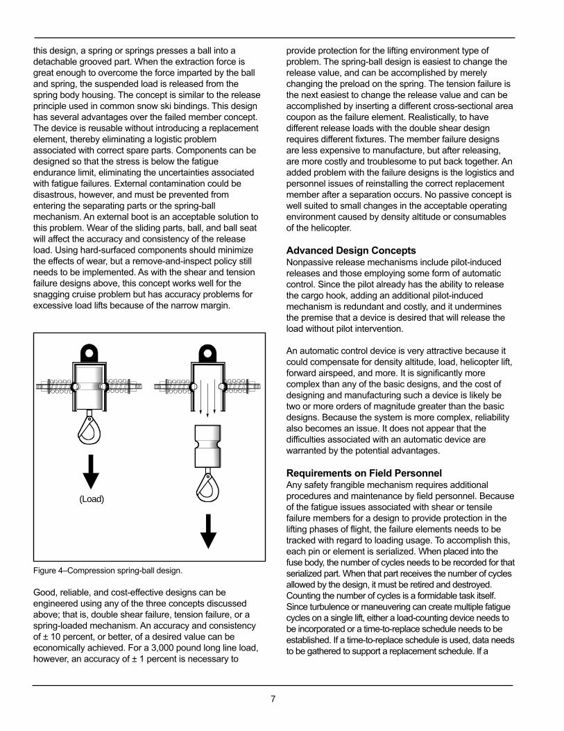
One example of an over-center mechanism is thecompression spring-ball mechanism shown in figure 4. In
(Load)
(Load)
(Load)
7
this design, a spring or springs presses a ball into adetachable grooved part. When the extraction force isgreat enough to overcome the force imparted by the balland spring, the suspended load is released from thespring body housing. The concept is similar to the releaseprinciple used in common snow ski bindings. This designhas several advantages over the failed member concept.The device is reusable without introducing a replacementelement, thereby eliminating a logistic problemassociated with correct spare parts. Components can bedesigned so that the stress is below the fatigueendurance limit, eliminating the uncertainties associatedwith fatigue failures. External contamination could bedisastrous, however, and must be prevented fromentering the separating parts or the spring-ballmechanism. An external boot is an acceptable solution tothis problem. Wear of the sliding parts, ball, and ball seatwill affect the accuracy and consistency of the releaseload. Using hard-surfaced components should minimizethe effects of wear, but a remove-and-inspect policy stillneeds to be implemented. As with the shear and tensionfailure designs above, this concept works well for thesnagging cruise problem but has accuracy problems forexcessive load lifts because of the narrow margin.
Figure 4–Compression spring-ball design.
Good, reliable, and cost-effective designs can beengineered using any of the three concepts discussedabove; that is, double shear failure, tension failure, or aspring-loaded mechanism. An accuracy and consistencyof ± 10 percent, or better, of a desired value can beeconomically achieved. For a 3,000 pound long line load,however, an accuracy of ± 1 percent is necessary to
provide protection for the lifting environment type ofproblem. The spring-ball design is easiest to change therelease value, and can be accomplished by merelychanging the preload on the spring. The tension failure isthe next easiest to change the release value and can beaccomplished by inserting a different cross-sectional areacoupon as the failure element. Realistically, to havedifferent release loads with the double shear designrequires different fixtures. The member failure designsare less expensive to manufacture, but after releasing,are more costly and troublesome to put back together. Anadded problem with the failure designs is the logistics andpersonnel issues of reinstalling the correct replacementmember after a separation occurs. No passive concept iswell suited to small changes in the acceptable operatingenvironment caused by density altitude or consumablesof the helicopter.
Advanced Design ConceptsNonpassive release mechanisms include pilot-inducedreleases and those employing some form of automaticcontrol. Since the pilot already has the ability to releasethe cargo hook, adding an additional pilot-inducedmechanism is redundant and costly, and it underminesthe premise that a device is desired that will release theload without pilot intervention.
An automatic control device is very attractive because itcould compensate for density altitude, load, helicopter lift,forward airspeed, and more. It is significantly morecomplex than any of the basic designs, and the cost ofdesigning and manufacturing such a device is likely betwo or more orders of magnitude greater than the basicdesigns. Because the system is more complex, reliabilityalso becomes an issue. It does not appear that thedifficulties associated with an automatic device arewarranted by the potential advantages.
Requirements on Field PersonnelAny safety frangible mechanism requires additionalprocedures and maintenance by field personnel. Becauseof the fatigue issues associated with shear or tensilefailure members for a design to provide protection in thelifting phases of flight, the failure elements needs to betracked with regard to loading usage. To accomplish this,each pin or element is serialized. When placed into thefuse body, the number of cycles needs to be recorded for thatserialized part. When that part receives the number of cyclesallowed by the design, it must be retired and destroyed.Counting the number of cycles is a formidable task itself.Since turbulence or maneuvering can create multiple fatiguecycles on a single lift, either a load-counting device needs tobe incorporated or a time-to-replace schedule needs to beestablished. If a time-to-replace schedule is used, data needsto be gathered to support a replacement schedule. If a
(Load)

8
counting device is used, the counter itself is an additionalpiece of equipment that needs to be designed andmaintained.
AnalysisIn the lift-snagging event, the onset of the increasing loadon the hook is controlled by the lifting capacity of thehelicopter at the density altitude. Assuming the lift isvertical and using the basic dynamics equation F = M * a,
L – WT – S = M
T * a
y(2)
where L is the helicopter lift, WT is the total weight of the
helicopter and load, S is the force on the load caused bythe snag, M
T is the total mass of the helicopter and load,
and ay is the vertical acceleration. If it is assumed that the
vertical acceleration is constant in normal liftingoperations, kinematic equations state that the a
y = (v
2 –
v1) / Dt. If it is assumed that the vertical motion of the
helicopter goes from rest to 100 fpm in 1 second,
ay = 1.7 ft/sec/sec = 0.05 g
Substituting back into equation 2 for normal operationswith S = 0, it is found that the lift equals 1.05 times theweight of the helicopter and load. If during the lift the loadbecomes snagged and the lift remains the same,equation 2 becomes
S = WT * ( 0.05 – a
y / g ) (3)
ay will be negative since the acceleration of the helicopter
will be toward the ground.By examining a free body diagram of just the load, it isfound that
F – WL – S = M
L * a
yL (4)
where F is the force in the long line, WL and M
L are the
weight and mass of the load, and ayL
is the acceleration ofthe load. Kinematic equations state
a * s = 1/2 v22 – 1/2 v
12 (5)
where a is the acceleration, s is the distance over which theacceleration a occurs, v
2 is the final velocity, and v
1 is the
initial velocity. Just before the snag occurs, the helicoptervelocity is v
1 and after the snag has stopped the helicopter,
the velocity is 0. Using equations 1, 3, 4, and 5, table 1 wasdeveloped. It relates the long line load factors and time tostop as functions of vertical speed and stopping distances.The distance is the distance the helicopter travels to come toa complete stop, a
y is the average vertical acceleration, the
time is the time to go from the vertical speed v1y
to rest, S isthe average force on the snag, F is the force in the long line,and “F / W
L” dynamic load ratio on the long line, “g” load.
Tables 1 and 2 assume the helicopter weighs 6,000 poundsand the load is 3,000 pounds.
In the case where the long line snags an object when thehelicopter has a significant forward velocity, the helicopteressentially pivots about the snag point going from ahorizontal velocity in an arc to a vertical velocity at impactwith the ground. The equation for the velocity v
2 at any
point on this arc is given by
v2 = [ 2 ρ g ( 1 – cos θ ) + v
12]
1/2(6)
where θ is the angle at which the nose of the helicopter isbelow the horizontal, where v
1 is the horizontal velocity
before the snag, v2 is the vertical velocity at the angle q,
and ρ is the length of the long line. Equation 6 applied tothe case for impact with the ground yields
v2 = [ 2 ρ g + v
12]
1/2(7)
where v2 is the vertical velocity at ground impact. The
force in the long line at impact is given by
F = L + 2 * WH +W
H * v
12 / ( ρ * g) (8)
where WH is the weight of the helicopter. The approximate
time for the helicopter to make the transition from normalhorizontal flight to impact is given by
∆t = π * ρ / ( v1 + v
2). (9)
Table 1—Accelerations with Vertical Lift at Hover
v1y
(fpm) v1y
(fps) Distance (ft) ay (ft/s/s) a
y (g’s) Time (s) S (lb) F (lb) F/W
L
10 0.17 1 -0.01 0.000 12 454 3,453 1.210 0.17 2 -0.01 0.000 24 452 3,451 1.2
100 1.67 0.25 -5.56 -0.173 0.3 2,003 4,485 1.5100 1.67 0.5 -2.78 -0.086 0.6 1,226 3,968 1.3100 1.67 1 -1.39 -0.043 1.2 838 3,709 1.2100 1.67 2 -0.69 -0.022 2.4 644 3,579 1.2500 8.33 1 -34.72 -1.078 0.24 10,155 9,920 3.3500 8.33 2 -17.36 -0.539 0.48 5,302 6,685 2.2

9
The vertical components of the velocity and accelerationare
vy = v * sin θ (10)
anda
y = a * sin θ (11)
For an initial horizontal velocity of 60 mph, which equals88 fps, equation 6 gives the forward velocities at 30, 60,and 90 degrees as 93, 105, and 119 fps, respectively. Foran object traveling on a circular path, additional kinematicequations are
∆θ = ωavg
* ∆t (12)and
ρ ωavg
= 1/2 (v1 + v
2 ) (13)
where ωavg
is the average angular velocity and ∆t is thetime for the nose angle ∆θ to occur. For a helicopterinitially traveling horizontally at 60 mph and becoming
snagged, the time to travel from a nose down angle of 30degrees to 60 degrees according to equations 12 and 13is only 0.530 seconds.
At a nose down angle of 60 degrees the helicopter has avertical velocity component by equation 10 of 91 fps. If atthis point the pilot has released the long line and isattempting to pull up, in order to avoid hitting the groundhis average vertical acceleration given by equation 5 mustbe greater than 82 ft/sec/sec. Equation 11 then states thatthe total acceleration must be 164 ft/sec/sec, or 5.1 g’s.The acceleration as in equation 11 exceeds the structuralstrength of the helicopter.
Table 2 relates the time to crash and long line load factorsas a function of the forward speed. As in table 1, F / W
L is
the load factor in g’s. Figure 5 illustrates the force causedby snagging load.
Table 2—Snag Data with Forward Speed
v1 (mph) v
1 (fps) v
2 (fps) Time (s) F (lb) F/W
L
10 14.7 82 3.26 21,851 7.330 44.0 92 2.32 25,057 8.460 88.0 119 1.52 35,880 12.0
100 146.7 167 1.00 61,533 20.5
Figure 5—Force caused by snagging load.
(Lift) (Velocity)

10
DiscussionThe basic concept of a frangible link appears to be inconflict with several requirements in FAA regulations.First, the FAA requires the pilot to have control over thedisposable load, and the fundamental premise of thisproposed device is that the pilot does not have to act torelease the load. Secondly, an FAA regulation states thatthe design strength must exceed the load factor times theworking load limit. This requirement completely eliminatesany possibility of employing a device that releases just alittle above the normal lift load as is required for densityaltitude, slight excessive overload, or a snag encounteredwhile lifting in hover.
A reliable safety mechanism can be designed andmanufactured to perform the basic function of loadseparation. Design criteria that meet the needs of bothhover lift problems and forward flight snag problems,however, are all essentially mutually exclusive. The verynarrow margin between normal operations and incidentfor hover lifting makes the design and manufacture of adevice very precise and very expensive. An additionaldifficulty is that the release force needs to be adjustablefor different empty helicopter weights, available enginepower, different consumables on board at the time of lift,and different density altitudes. Without some form ofautomatic control that has these inputs, a satisfactorydevice cannot be developed for the hover liftingscenarios. An automatic control device adds majorcomplexity and cost, and therefore is not practical.
Acceptable reliability can be achieved for any of thedesigns presented here. The problem regarding reliabilityis when the operating margin becomes very narrow, tohave high reliability requires high costs. Also for a morecomplex automatic control system to achieve highreliability the cost will be higher. Reliable and reproducibleresults for hover lifting can be obtained, but at very highcosts; and the system has to deal with the variability ofthe operating environment.
Because of the large margin between normal operationand incident, the forward flight safety link is much morefeasible. Any of the basic designs presented will workreliably at a reasonable cost. For this application, thedouble shear design is probably the most economical,followed by the tensile failure design, providing only a fewdifferent load settings are required. These two designsare also less complex than the over-center device. Anydevice has to be protected from environmental conditionssuch as dirt, dust, water, and chemicals. Becausedifferent devices or settings are required for differenthelicopters and different missions, an operator has toperform a function to have the device have the propersetting. By this adjustable nature, operator error ispossible, which introduces another set of problems.
Any device requires additional maintenance, logistics,and recordkeeping by field personnel. Training is requiredto ensure that a proper device and failure setting areinstalled for a given mission. Inspections andreplacement tasks are performed, and with any device, apotential exists to have an improperly sized failuremember installed on a given mission.
To perform the above analysis, a number of assumptionsand estimates were made. The results should not beconstrued to be accurate numerical values, but rather tosuggest trends and relative magnitudes. In the hovermode, the vertical acceleration is small and the lift of thehelicopter is not much higher than the combined weight ofthe helicopter and load. Whether the lift is 1.02 or 1.15times the weight is immaterial. The numeric values intable 1 are conservative estimates in that the distance tostop after the snag is encountered is probably greaterthan the 0.25 to 2 feet shown. Therefore, the actualaccelerations ay, snag forces S, long line forces F, andratio of F to weight are lower than those shown in thetable. The time to stop would be greater than tabulatedvalues. The results of table 1 show that the time for theincident to occur is relatively large and the load factorsare within the design parameters of flight hardware. Thetime in the table is what is necessary to stop thehelicopter’s vertical velocity. For an incident to occur,something must happen after the helicopter comes to azero vertical velocity, and this takes additional amounts oftime. Two things are significant here: First, the loadfactors should not cause a structural failure in thehelicopter, and secondly, there is enough time while theevent is developing for the pilot to react and manuallyrelease the load. Since events happen slowly, a properlytrained pilot has adequate time to recognize the problemand react accordingly without an incident. The hover liftoverload or snag situation should not jeopardize thesafety of the helicopter or crew.
Table 2 addresses the situation in which the helicopterhas a significant forward velocity and the long linebecomes entangled with an immovable object. At theinstant the snag occurs, the helicopter starts traveling in acircular arc in a vertical plane about the fixed point. Theradius of the arc is the length of the long line. The shorterthe long line, the quicker the incident will occur. Table 2shows that even at modest forward speeds there is verylittle time between encountering the snag and thehelicopter’s crashing to the ground. Traveling forward at60 mph the total time for the incident is just 1.5 seconds.Because of the nature of the motion of moving on an arc,it is probable that the pilot would be unaware thatanything abnormal were happening for the first 10percent of this time. Then the pilot would have to identifythe problem and react to release the load. At this sametime the pilot and helicopter would be subjected to 12 g’s.

11
This force alone is enough to have ultimate structuralfailures in the helicopter. If the helicopter survived the firstpart of the arc and if the pilot were able to release theload by the time the nose is pointed down 60 degrees,the helicopter would still have to pull 5 g’s to avoid strikingthe ground. Helicopters are not capable of maneuveringat 5 g load factors. This simple analysis confirms whatmost people already suspect; at 60 mph, if the long linebecomes entangled, it is impossible to avoid an incident.For a snag incident to occur, an almost rhetorical questionshould be asked: Why was the helicopter cruising so lowin the first place?
The above analysis shows that two very different incidentmodes exist. The lifting-in-hover problem involvesrelatively small load factors and develops slowly enoughfor corrective action to be taken. The entanglement-while-cruising mode happens very quickly and the loads areenormous.
Conclusions1. Since there are few documented incidents in the
past where the long line caused a flight-endangering safety problem, it is difficult to justifyadding an additional and new piece of equipmentto the long line system.
2. FAA regulations require that the pilot be in controlof all releases of slung loads; that is, noautomatic release devices.
3. The necessity of a safety link can not besubstantiated for dynamic loading caused by airturbulence since the pilot has adequate time toreact and manually release the load.
4. Without employing some form of automaticcontrol, it is impossible to have a device protectthe lifting environment where very small changesin helicopter capability caused by density altitudeand consumables on board differentiate betweena successful operation and an incident.
5. Two different protection devices are neededbecause the requirements for lift protection areso much different than those for ground snagsduring cruise.
6. In hover, a properly trained pilot should haveadequate time to recognize the problem andreact accordingly. The hover lift overload or hoversnag situation should not jeopardize the safety ofthe helicopter or crew.
7. A significant logistics problem would exist to trackthe critical components, have spares on hand,and perform the necessary inspections andmaintenance. This burden would result in errorsof implementation, which would create moreinadvertent releases and different safety issues.
8. Realistically, a protection device for the hovermode is not feasible.
9. A protection device for cruise entanglements isdesignable and producable at a reasonable cost.There does not appear to be justification,however, for the trouble of pursuing this concept.
RecommendationsWhile increased safety for helicopter operationsaccomplished by natural resource agencies is always thegoal, the development of a breaking link for slung loadsdoes not appear to be a proper implementation.