Unit2 (Centrifugal Pump)
39
PUMPS: CENTRIFUGAL PUMPS G 2006/UNIT 2/1 PUMPS: CENTRIFUGAL PUMPS OBJECTIVES General Objective To know the basic operational principles, characteristics, main parts and functions of centrifugal pumps. Specific Objectives At the end of this unit, you should be able to describe: the basic operational principle of centrifugal pumps UNIT
-
Upload
kogulan-subramaniam -
Category
Documents
-
view
47 -
download
3
description
centrifugal pump
Transcript of Unit2 (Centrifugal Pump)
PUMPS: CENTRIFUGAL PUMPS G 2006/UNIT 2/1
PUMPS: CENTRIFUGAL PUMPS
OBJECTIVES
General Objective
To know the basic operational principles, characteristics, main parts and functions of centrifugal pumps.
Specific Objectives
At the end of this unit, you should be able to describe:
the basic operational principle of centrifugal pumps
the characteristics of centrifugal pumps
the main parts of centrifugal pumps and their functions
UNIT 2
INPUT
PUMPS: CENTRIFUGAL PUMPS G 2006/UNIT 2/2
2.0 INTRODUCTION
Centrifugal pumps employ centrifugal force and velocity to create pressure. The
mechanical element is an impeller, which is a rotating disc with vanes. The inlet
flow to the pump is directed into the centre of the spinning impeller and the
centrifugal force throws the liquid at high velocity into the surrounding casing.
2.1 BASIC OPERATIONAL PRINCIPLE OF CENTRIFUGAL PUMPS
The energy of a liquid may be increased by pumping it. Centrifugal force is the
force of spinning. When an object is spun around in a circle, it pushes outward
from the centre of the circle. This outward force is called the centrifugal force.
This is how a centrifugal pump works. Centrifugal pumps are machines which
move liquids by means of centrifugal forces. Centrifugal force is the force in a
rotating body which makes particles move away from it centre.
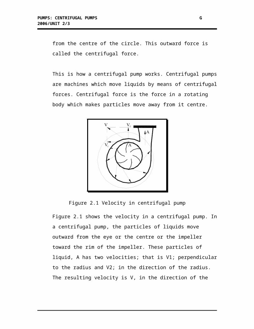
Figure 2.1 Velocity in centrifugal pump
PUMPS: CENTRIFUGAL PUMPS G 2006/UNIT 2/3
Figure 2.1 shows the velocity in a centrifugal pump. In a centrifugal pump, the
particles of liquids move outward from the eye or the centre or the impeller
toward the rim of the impeller. These particles of liquid, A has two velocities; that
is V1; perpendicular to the radius and V2; in the direction of the radius. The
resulting velocity is V, in the direction of the particles of the liquid leaving the
rim of the impeller.
The resulting V or velocity known as tangential velocity enters the casing of the
pumps where its velocity decreases and where a large part of the velocity energy
is converted to pressure energy to have greater pressure on the pump outlet.
2.2 CHARACTERISTICS OF CENTRIFUGAL PUMPS
Pumps are rated according to their pumping characteristics and according to
things you need to know to operate the pump efficiently. Rating helps you to
select the right pump for your operations.
For example, a certain pump delivers 100 gallons per minute (GPM). The pump
has a rated velocity of 100 GPM. Capacity is usually a factor in rating a pump.
Suction and discharge pressure also affect the rating of pump. For example, a
pump produces a discharge pressure of 30 PSIG. It has a rated discharge pressure
of 30 PSIG.
2.2.1 Capacity
The capacity of a pump is the amount of liquid that the pump moves in a
given length of time. Capacity is usually measured in gallons per minute,
abbreviated as GPM. Pump capacity can be changed by changing the
speed of impeller. Therefore, increasing pump speed also increases pump
velocity. The pump and its prime mover usually run best within a range of
PUMPS: CENTRIFUGAL PUMPS G 2006/UNIT 2/4
specific speeds. Increasing pump capacity by increasing its RPM is not
always practical.
2.2.2 Pressure and Head
Pressure is the force acting on a unit of area. Head is the height of a liquid.
Suction head is the sum of pressure changed to head, plus the velocity of
head at the inlet to the pump while discharge head is the sum of the
pressure changed to head at the outlet of the pump.
Velocity head is normally small and is not used in pumping calculations.
The total head is the discharge head plus or minus the suction head. Or,
total head can be calculated by reading the pressure at the pump suction
and discharge and converting this pressure measurement to head
measurements.
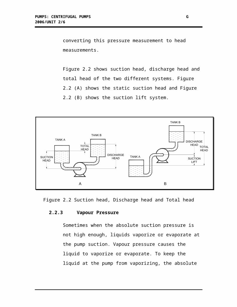
Figure 2.2 shows suction head, discharge head and total head of the two
different systems. Figure 2.2 (A) shows the static suction head and Figure
2.2 (B) shows the suction lift system.
Figure 2.2 Suction head, Discharge head and Total head
2.2.3 Vapour Pressure
PUMPS: CENTRIFUGAL PUMPS G 2006/UNIT 2/5
Sometimes when the absolute suction pressure is not high enough, liquids
vaporize or evaporate at the pump suction. Vapour pressure causes the
liquid to vaporize or evaporate. To keep the liquid at the pump from
vaporizing, the absolute suction pressure must be higher than the vapour
pressure of the liquid at that temperature.
2.2.4 Net Positive Suction Head (NPSH)
Net positive suction head (NPSH) is the absolute suction head minus the
vapour pressure head. If suction head is 50 feet and vapour pressure is 35
feet, NPSH is 15 feet.
NPSH available is the absolute pressure at pump suction, changed to head,
minus the vapour pressure of the liquid being pumped and changed to
head. NPSH required is the minimum head needed at the suction to get the
liquid into the impeller without vaporizing.
If NPSH available is equal to NPSH required, the pump may lose suction
due to slight variations in pump design. Therefore NPSH available must
be then NPSH required.
2.2.5 Friction
During flow, pressure is converted to velocity. As velocity increases
during flow, pressure increases. Pressure between two points in fluids flow
is called the pressure drop. For fluid to flow, the driving force must be
greater than the resisting force. Thus, the pressure drop must be greater
than the amount of friction.
2.2.6 Horsepower
PUMPS: CENTRIFUGAL PUMPS G 2006/UNIT 2/6
Horsepower is a unit used for measuring rate of work. It is necessary to
overcome friction and other losses and to move the liquid provided by the
prime mover or driver. The amount of useful work that a pump delivers is
the difference between the pressure the liquid has as it enters the pump
and the pressure it has as it leaves the pump.
The horsepower input is always more than the fluid horsepower or
horsepower output. Overall efficiency of a pump is the percentage of the
HP input that is transferred to the liquid leaving the pump or is found by
dividing the HP output by the HP input.
2.3 PERFORMANCES CURVE
All centrifugal pumps come with a set of performance curves. These curves can
be used to find the NPSH, total head, efficiency, and HP for each pump at
different capacities. The performance curves can also show some general
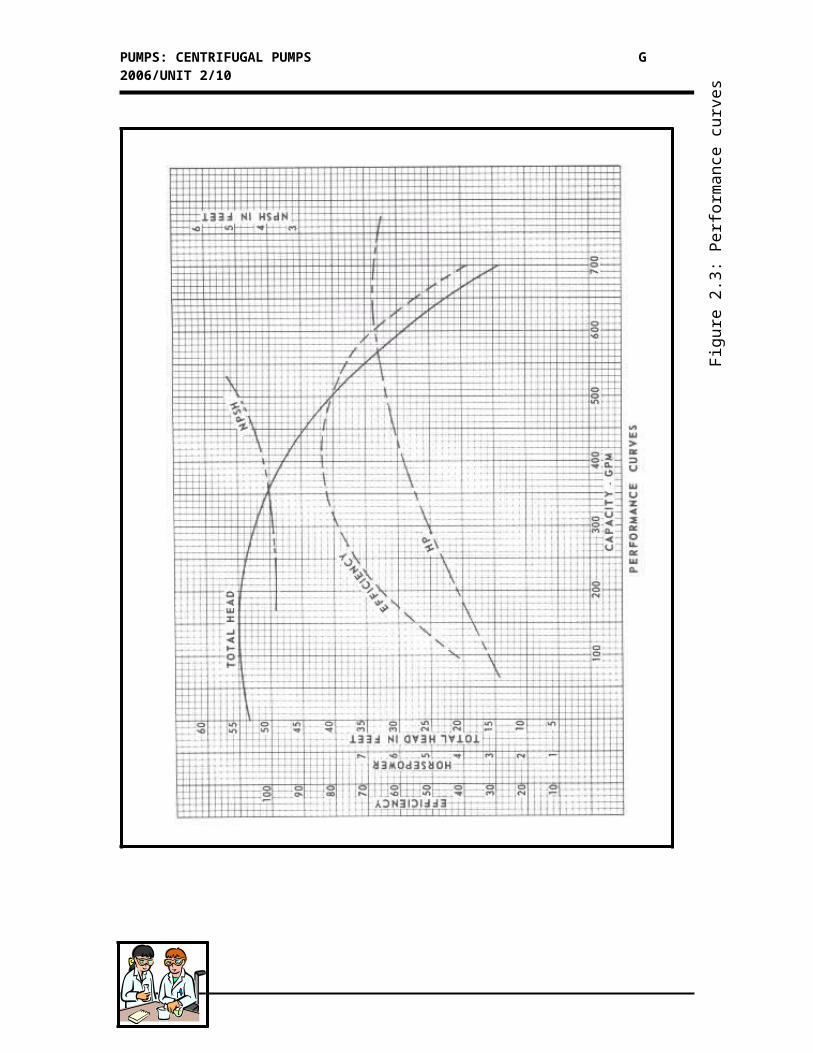
principles of centrifugal pump performance. Figure 2.3 shows performance curves
of centrifugal pumps.
According to Figure 2.3, as the pumping rate increases, the NPSH required
increases. The efficiency of a pump is relatively low at high and low flow rates.
As the flow rate increases, the horsepower required increases.
KEY FACTS:
Centrifugal pumps employ centrifugal force and velocity to create pressure.Pumps are rated according to their pumping characteristics.The performance curve shows some general principles of centrifugal pump
performance.
PUMPS: CENTRIFUGAL PUMPS G 2006/UNIT 2/7
Fig
ure
2.3:
Per
form
ance
cur
ves
PUMPS: CENTRIFUGAL PUMPS G 2006/UNIT 2/8
Activity 2A
Let’s test your understanding by answering these questions.
2.1 Fill in the blanks with appropriate answers.
Centrifugal pumps employ (A) and velocity to create pressure.
The mechanical element is an (B) , which is a rotating disc with
vane. Centrifugal pumps are machines which move (C) by means
of centrifugal forces. Centrifugal force is the force in a (D) which
makes particles move away from it centre.
2.2 The particles of liquid have two velocities. They are…
i. _____________________________
ii. _____________________________
2.3 List four characteristics of pumps
i. __________________________________
ii. __________________________________
iii. __________________________________
iv. __________________________________
2.4 What is the purpose of performances curve?
Check your answer on the next page…
INPUT
PUMPS: CENTRIFUGAL PUMPS G 2006/UNIT 2/9
Feedback to Activity 2A
Here are the answers.
2.1 (A) centrifugal force
(B) impeller
(C) liquids
(D) rotating body
2.2 i. tangential velocity
ii. perpendicular velocity
2.3 Any four of the following
i. Capacity and/or
ii. Pressure head and/or
iii. Vapour pressure and/or
iv. (HPSH) and/or
v. Friction and/or
vi. Horsepower
2.4 The performances curve can be used to find the NPSH, total head, efficiency, and
HP for each pump at different capacities.
The next input will focus on main parts of centrifugal pumps…
Centrifugal pumps are machines which move liquids by means of centrifugal forces. An impeller is one of the important parts in centrifugal pumps. How about the other components?
PUMPS: CENTRIFUGAL PUMPS G 2006/UNIT 2/10
2.4 MAIN PARTS OF CENTRIFUGAL PUMPS AND THEIR FUNCTIONS
In the previous section we have already introduced the characteristics of
centrifugal pumps that are important to determine the appropriate selection of a
pump for a certain pumping process. In this section we are going to study the
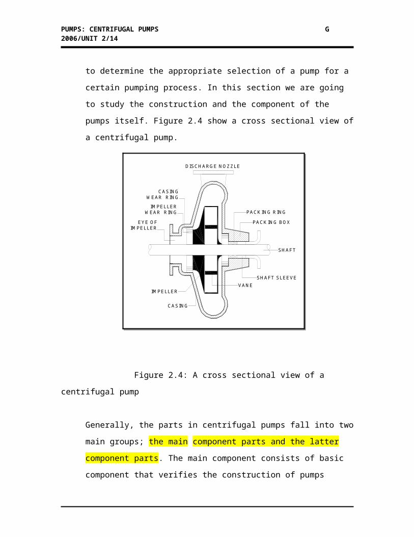
construction and the component of the pumps itself. Figure 2.4 show a cross
sectional view of a centrifugal pump.
Figure 2.4: A cross sectional view of a centrifugal pump
Generally, the parts in centrifugal pumps fall into two main groups; the main
component parts and the latter component parts. The main component consists of
PACK ING BOX
PACK ING RING
SHAFT
VANE
SHAFT SLEEVE
CASING
DISCHARGE NOZZLE
IMPELLER
EY E OFIMPELLER
CASING WEAR RING
IMPELLER WEAR RING
PUMPS: CENTRIFUGAL PUMPS G 2006/UNIT 2/11
basic component that verifies the construction of pumps itself while the latter
component is supporting component that helps the pumps run efficiently.
2.4.1 Main Component parts of Centrifugal Pump
There are three main component parts of centrifugal pump:
i. Pump casing
ii. Impeller
iii. Stuff or seal box
Pump Casing
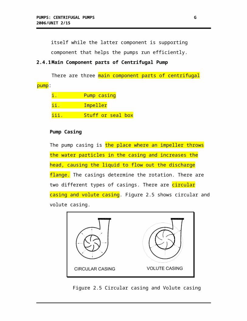
The pump casing is the place where an impeller throws the water particles in the
casing and increases the head, causing the liquid to flow out the discharge flange.
The casings determine the rotation. There are two different types of casings. There
are circular casing and volute casing. Figure 2.5 shows circular and volute casing.
Figure 2.5 Circular casing and Volute casing
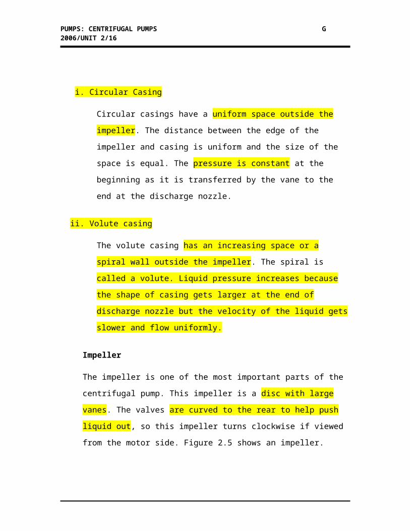
i. Circular Casing
Circular casings have a uniform space outside the impeller. The distance
between the edge of the impeller and casing is uniform and the size of the
space is equal. The pressure is constant at the beginning as it is transferred by
the vane to the end at the discharge nozzle.
ii. Volute casing
PUMPS: CENTRIFUGAL PUMPS G 2006/UNIT 2/12
The volute casing has an increasing space or a spiral wall outside the impeller.
The spiral is called a volute. Liquid pressure increases because the shape of
casing gets larger at the end of discharge nozzle but the velocity of the liquid
gets slower and flow uniformly.
Impeller
The impeller is one of the most important parts of the centrifugal pump. This
impeller is a disc with large vanes. The valves are curved to the rear to help push
liquid out, so this impeller turns clockwise if viewed from the motor side. Figure
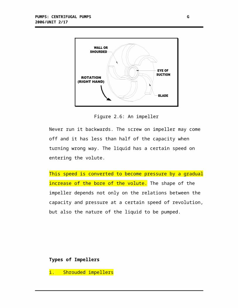
2.5 shows an impeller.
Figure 2.6: An impeller
Never run it backwards. The screw on impeller may come off and it has less than
half of the capacity when turning wrong way. The liquid has a certain speed on
entering the volute.
This speed is converted to become pressure by a gradual increase of the bore of
the volute. The shape of the impeller depends not only on the relations between
the capacity and pressure at a certain speed of revolution, but also the nature of
the liquid to be pumped.
PUMPS: CENTRIFUGAL PUMPS G 2006/UNIT 2/13
Types of Impellers
i. Shrouded impellers
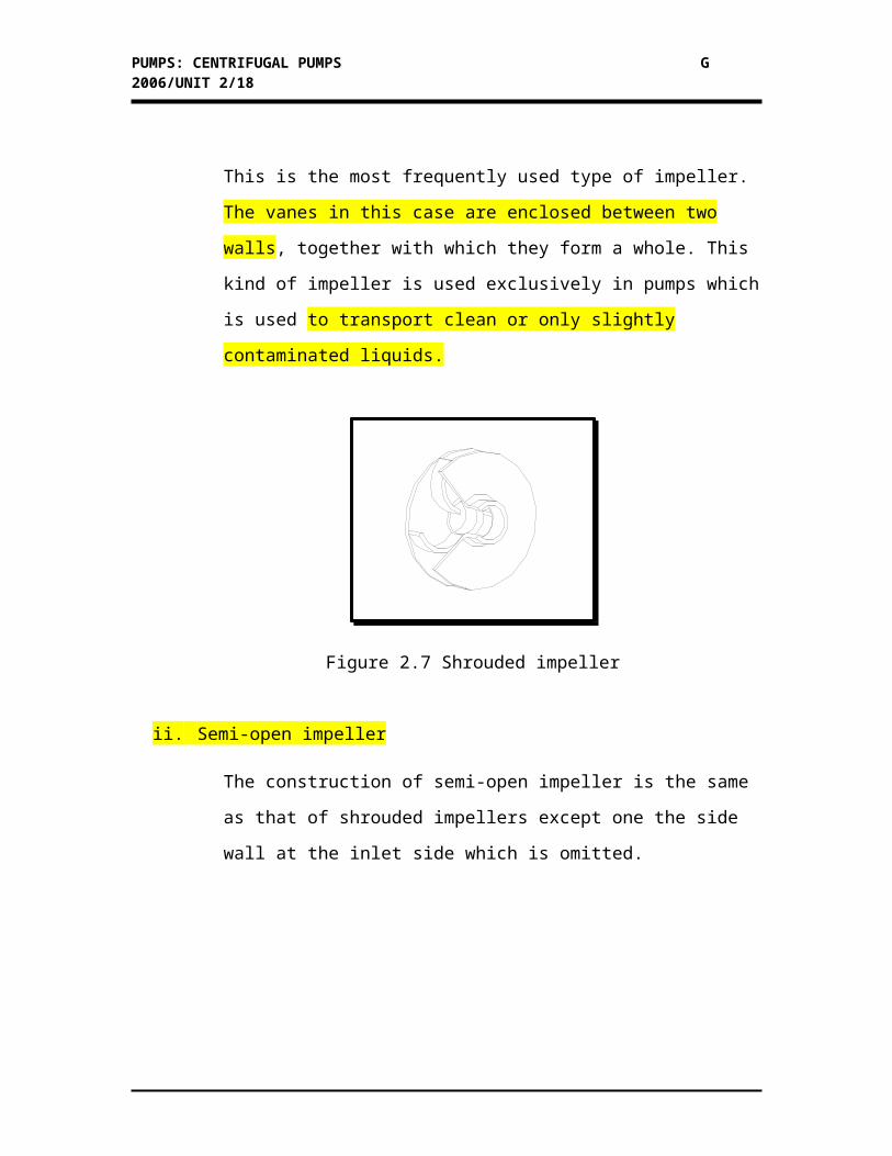
This is the most frequently used type of impeller. The vanes in this case are
enclosed between two walls, together with which they form a whole. This
kind of impeller is used exclusively in pumps which is used to transport
clean or only slightly contaminated liquids.
Figure 2.7 Shrouded impeller
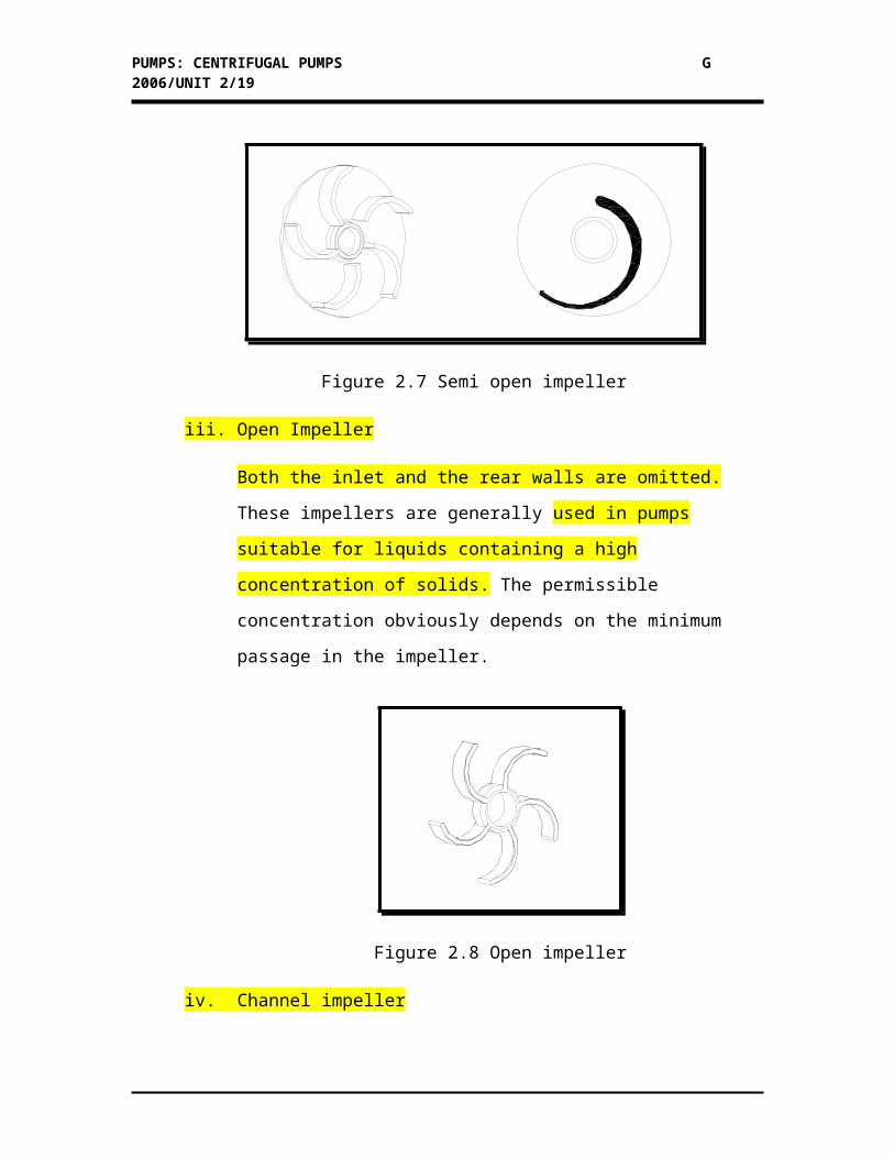
ii. Semi-open impeller
The construction of semi-open impeller is the same as that of shrouded
impellers except one the side wall at the inlet side which is omitted.
PUMPS: CENTRIFUGAL PUMPS G 2006/UNIT 2/14
Figure 2.7 Semi open impeller
iii. Open Impeller
Both the inlet and the rear walls are omitted. These impellers are generally
used in pumps suitable for liquids containing a high concentration of
solids. The permissible concentration obviously depends on the minimum
passage in the impeller.
Figure 2.8 Open impeller
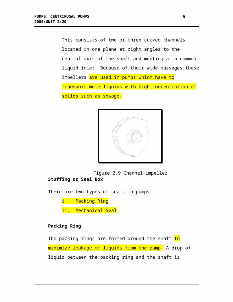
iv. Channel impeller
This consists of two or three curved channels located in one plane at right
angles to the central axis of the shaft and meeting at a common liquid
inlet. Because of their wide passages these impellers are used in pumps
which have to transport more liquids with high concentration of solids
such as sewage.
PUMPS: CENTRIFUGAL PUMPS G 2006/UNIT 2/15
Figure 2.9 Channel impellerStuffing or Seal Box
There are two types of seals in pumps:
i. Packing Ring
ii. Mechanical Seal
Packing Ring
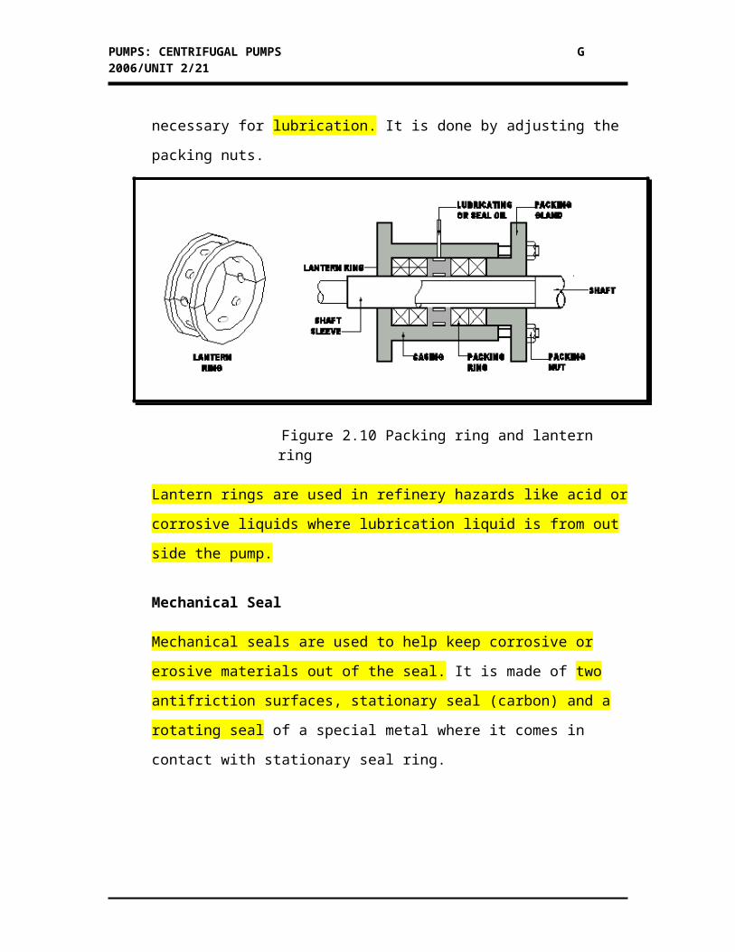
The packing rings are formed around the shaft to minimize leakage of liquids
from the pump. A drop of liquid between the packing ring and the shaft is
necessary for lubrication. It is done by adjusting the packing nuts.
Figure 2.10 Packing ring and lantern ring
Lantern rings are used in refinery hazards like acid or corrosive liquids where
lubrication liquid is from out side the pump.
Mechanical Seal
Mechanical seals are used to help keep corrosive or erosive materials out of the
seal. It is made of two antifriction surfaces, stationary seal (carbon) and a rotating
seal of a special metal where it comes in contact with stationary seal ring.
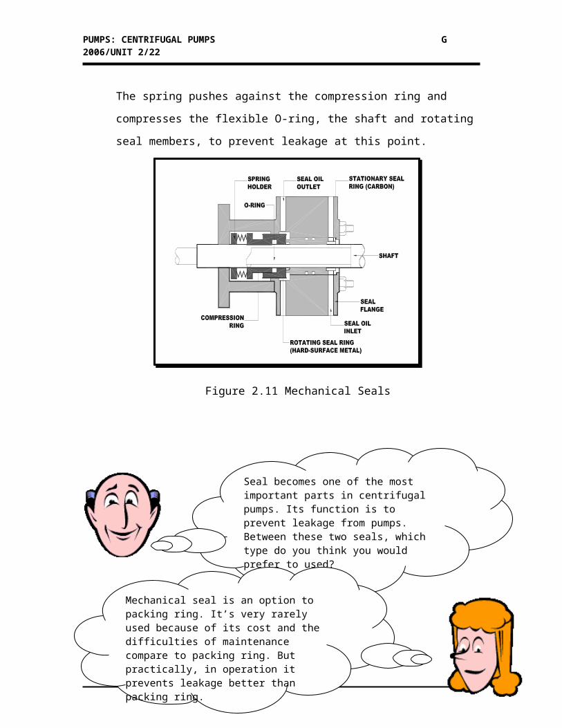
The spring pushes against the compression ring and compresses the flexible O-
ring, the shaft and rotating seal members, to prevent leakage at this point.
PUMPS: CENTRIFUGAL PUMPS G 2006/UNIT 2/16
Figure 2.11 Mechanical Seals
Seal becomes one of the most important parts in centrifugal pumps. Its function is to prevent leakage from pumps. Between these two seals, which type do you think you would prefer to used?
Mechanical seal is an option to packing ring. It’s very rarely used because of its cost and the difficulties of maintenance compare to packing ring. But practically, in operation it prevents leakage better than packing ring.
PUMPS: CENTRIFUGAL PUMPS G 2006/UNIT 2/17
2.4.2 Latter components of centrifugal pumps
There are three latter components of the centrifugal pump. They are:
i. Shaft
ii. Bearing
iii. Wear plate or Wear Ring
Shafts
The shaft is a smooth and straight solid material where it fits into bearings to
transmit power to the impeller.
Bearing
Bearings are use to support the shaft and allow it to rotate freely without
dragging. It also controls radial and axial movements of the shaft that may reduce
the time of failure of the packing or mechanical seal. Bearings are set nearest the
couplings and impeller with locking collars.
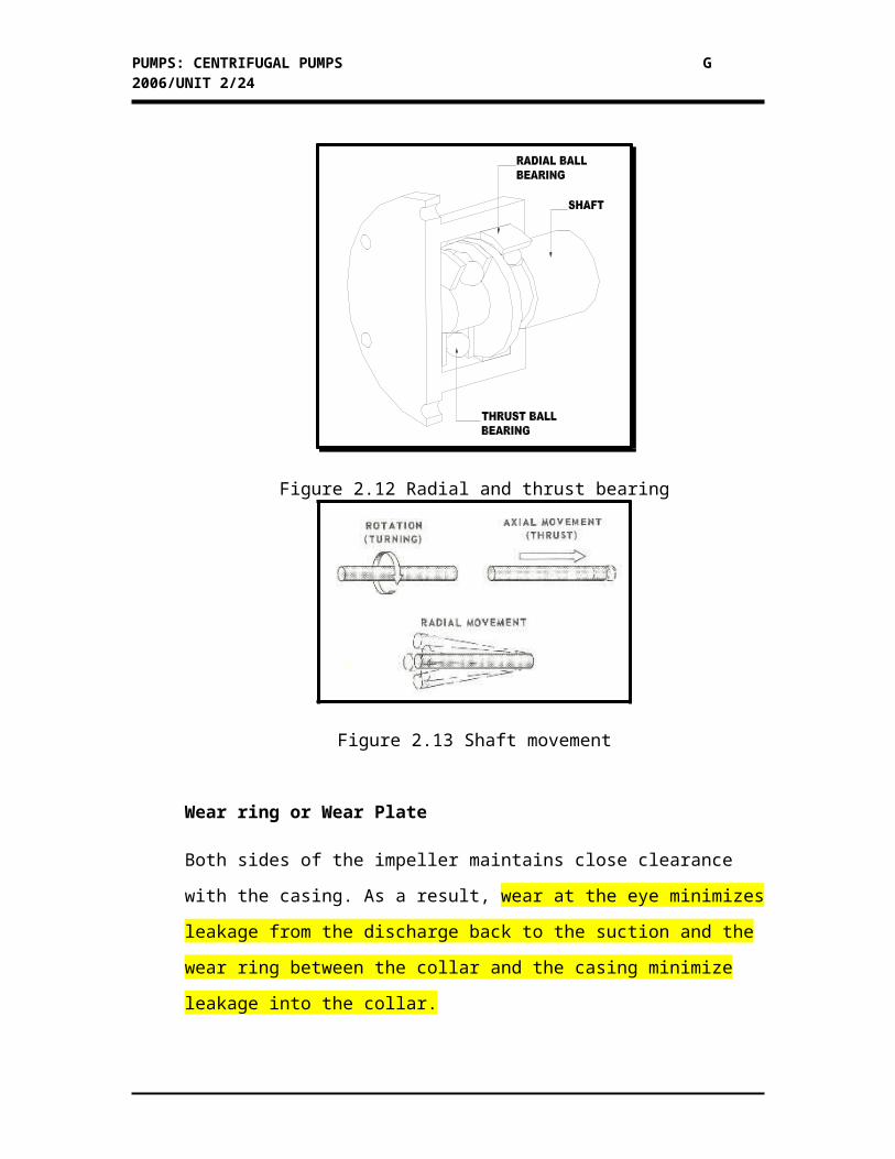
Figure 2.12 Radial and thrust bearing
PUMPS: CENTRIFUGAL PUMPS G 2006/UNIT 2/18
Figure 2.13 Shaft movement
Wear ring or Wear Plate
Both sides of the impeller maintains close clearance with the casing. As a result,
wear at the eye minimizes leakage from the discharge back to the suction and the
wear ring between the collar and the casing minimize leakage into the collar.
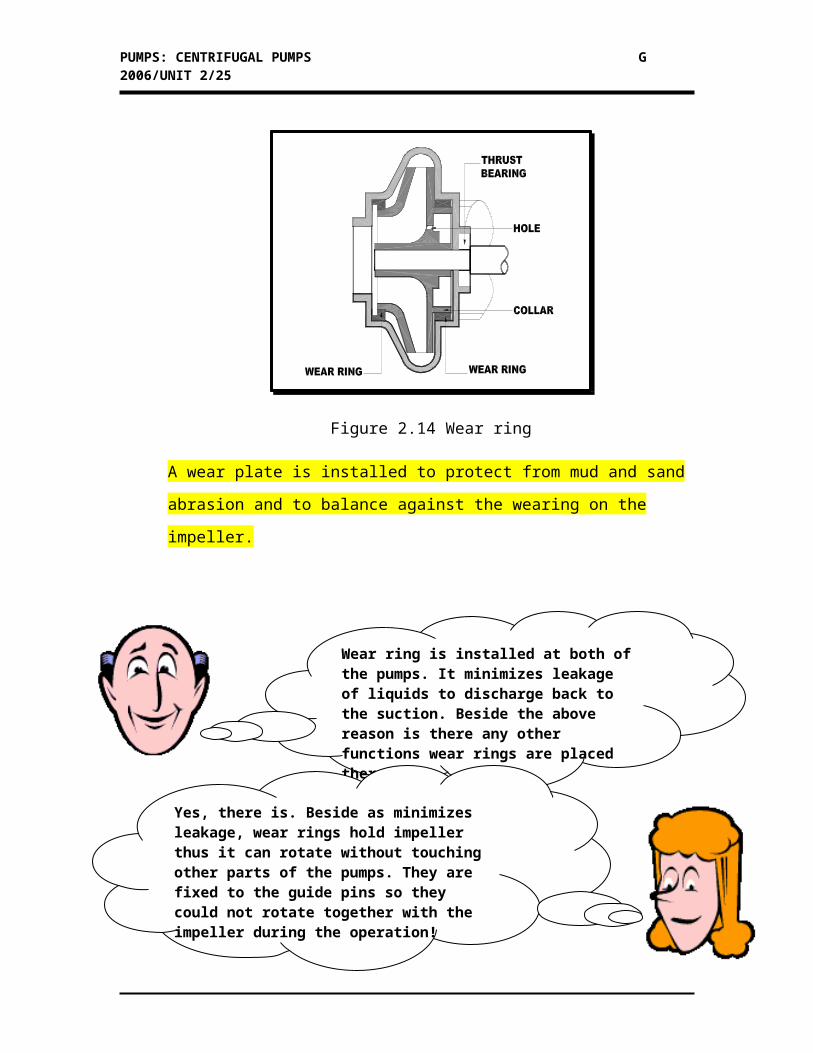
Figure 2.14 Wear ring
A wear plate is installed to protect from mud and sand abrasion and to balance
against the wearing on the impeller.
Wear ring is installed at both of the pumps. It minimizes leakage of liquids to discharge back to the suction. Beside the above reason is there any other functions wear rings are placed there?
Yes, there is. Beside as minimizes leakage, wear rings hold impeller thus it can rotate without touching other parts of the pumps. They are fixed to the guide pins so they could not rotate together with the impeller during the operation!
PUMPS: CENTRIFUGAL PUMPS G 2006/UNIT 2/19
To the next activity…
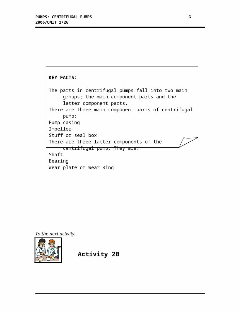
KEY FACTS:
The parts in centrifugal pumps fall into two main groups; the main component parts and the latter component parts.
There are three main component parts of centrifugal pump:Pump casing ImpellerStuff or seal boxThere are three latter components of the centrifugal pump. They are:ShaftBearingWear plate or Wear Ring
PUMPS: CENTRIFUGAL PUMPS G 2006/UNIT 2/20
Activity 2B
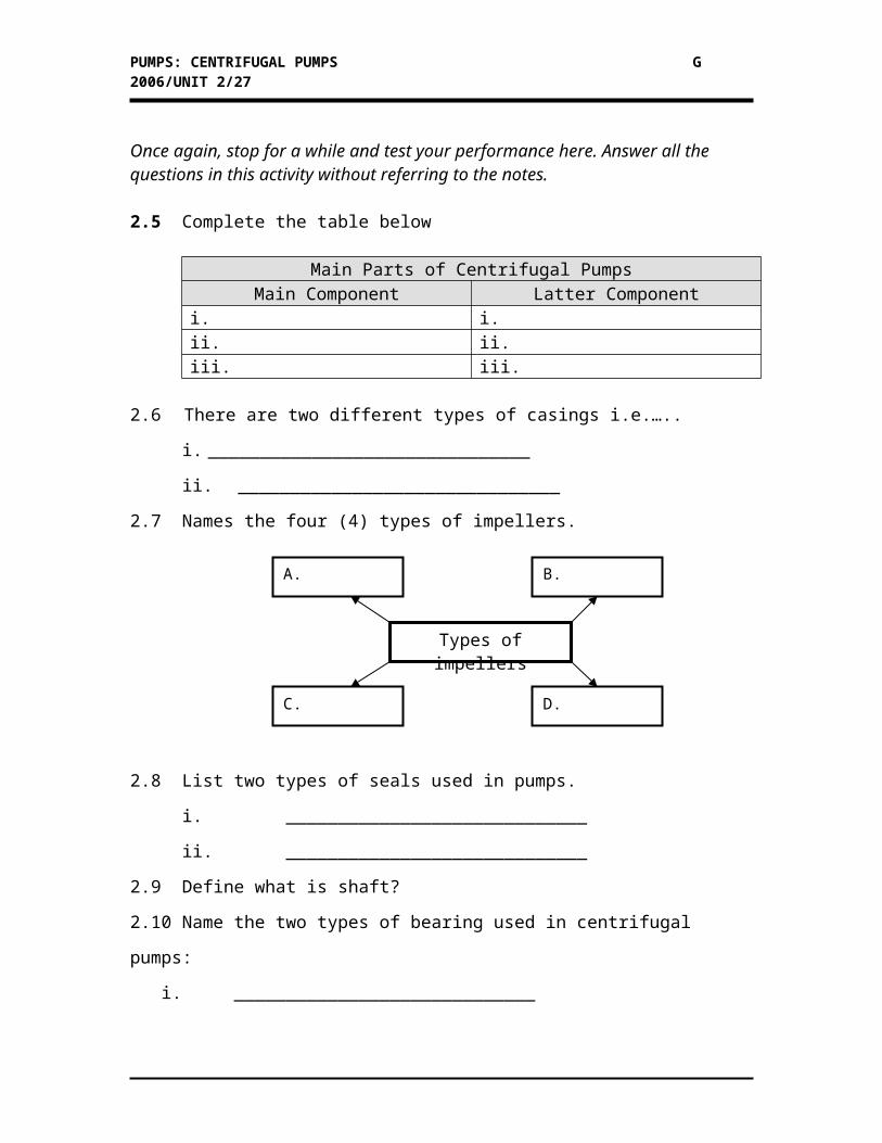
Once again, stop for a while and test your performance here. Answer all the questions in this activity without referring to the notes.
2.5 Complete the table below
Main Parts of Centrifugal PumpsMain Component Latter Component
i. i.ii. ii.iii. iii.
2.6 There are two different types of casings i.e.…..
i. _______________________________
ii. _______________________________
2.7 Names the four (4) types of impellers.
2.8 List two types of seals used in pumps.
i. _____________________________
ii. _____________________________
2.9 Define what is shaft?
2.10 Name the two types of bearing used in centrifugal pumps:
i. _____________________________
ii. _____________________________
2.11 What is the difference between wear rings and wear plate?
Are you centrifuging enough right now? Then we’ll see next page…
Types of impellers
B.
C.
A.
D.
PUMPS: CENTRIFUGAL PUMPS G 2006/UNIT 2/21
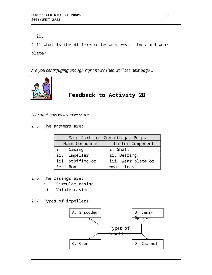
Feedback to Activity 2B
Let count how well you’ve score…
2.5 The answers are:
Main Parts of Centrifugal PumpsMain Component Latter Component
i. Casing i. Shaftii. Impeller ii. Bearingiii. Stuffing or Seal Box iii. Wear plate or wear rings
2.6 The casings are:i. Circular casingii. Volute casing
2.7 Types of impellers
2.8 Two types of seals are:i. Packing ringsii. Mechanical seal
2.9 The shaft is a smooth and straight solid material where it fits into bearings to transmit power to the impeller.
2.10 Name the two types of bearing used in centrifugal pumps:
i. Radial ball bearingii. Thrust ball bearing
Types of impellers
B. Semi-Open
C. Open
A. Shrouded
D. Channel
PUMPS: CENTRIFUGAL PUMPS G 2006/UNIT 2/22
2.11 Wear rings are located both at the end of the impeller to minimize leakage from discharge back to the suction while wear plate is installed to protect from mud and sand abrasion and to balance against the wear rings on the impeller.
SELF-ASSESSMENT UNIT 2
The previous activities are so simple. Now try the more challenging questions in this self assessment. Answer all the questions. If you need extra revision, you are encouraged to do so.
1. What is a centrifugal pump?
2. Describe how are centrifugal force and velocity applied in centrifugal
pumps. Draw a figure to assist your answer.
3. Look at figure 1.
Figure 1
a. Define
i. Suction head
ii. Suction lift head
iii. Discharge head
iv. Total head
b. Find the value of the following :
i. Figure A : Suction head, discharge head, total head
ii. Figure B: Suction lift, discharge head, total head
PUMPS: CENTRIFUGAL PUMPS G 2006/UNIT 2/23
4. Look at the performances curves in page 7 in unit 2.
At the capacity of 500 GPM, find these values.
i. Total head
ii. NPSH
iii. Horsepower
iv. Efficiency
5. Label the components A-G in the cross sectional view of a centrifugal pumps in
Figure 2.
E
G
H
F
VANE
B
IMPELLER WEAR RING
APACK ING BOX
D
C
Figure 2
6. What are the differences between circular casing and volute casing?
7. Explain impellers in the perspective of:
i. Design
ii. Assembly
iii. Principles of operation
iv. Types of impeller
8. Differentiate between packing ring and mechanical seal
PUMPS: CENTRIFUGAL PUMPS G 2006/UNIT 2/24
9. Figure 3 show typical type of bearing used in a centrifugal pump. Explain the
functions of each type of them.
Figure 3: Radial and thrust bearings
Tired..??? Rest for a few minutes and check your score in the next page…
PUMPS: CENTRIFUGAL PUMPS G 2006/UNIT 2/25
Feedback to Self-Assessment Unit 2
Let check your answer now.
1. Centrifugal pumps are machines which move liquids by means of centrifugal
forces. Centrifugal pumps employ centrifugal force and velocity to create
pressure. The mechanical element is an impeller, which is a rotating disc with
vanes. The inlet flow to the pump is directed into the centre of the spinning
impeller and the centrifugal force throws the liquid at high velocity into the
surrounding casing.
2. Centrifugal force is the force in a rotating body which makes particles move away
from it centre.
Velocity in centrifugal pump
The figure above shows the velocity in a centrifugal pump. In a centrifugal pump,
the particles of liquids move outward from the eye or the centre or the impeller
toward the rim of the impeller. These particles of liquids, A has two velocities;
that is V1; perpendicular to the radius and V2; in the direction of the radius. The
resulting velocity is V, in the direction of the particles of the liquid leaving the
rim of the impeller.
PUMPS: CENTRIFUGAL PUMPS G 2006/UNIT 2/26
The resulting V or velocity known as tangential velocity enters the casing of the
pumps where its velocity decreases and where a large part of the velocity energy
is converted to pressure energy to have greater pressure on the pump outlet
3.
a. According to Figure 1 (A) and (B)
i. Suction head is the water height measured from the suction tank A that
located relatively above the pumps centre.
ii. Suction lift is the water height measured from the suction tank A that
located relative below the pumps centre.
iii. Discharge head is water height measured relatively from the pumps centre
to the higher level in discharge tank B.
iv. Total head is the addition of subtraction between suction head or suction
lift and discharge head.
b.
i. Figure A : Suction head : 50 m, Discharge head : 75 m, Total head : 25 m
ii. Figure B : Suction lift : 75 m, Discharge head : 20 m, Total head : 55 m
4. The values are:
i. 40 feet
ii. 5 feet
iii. 6.4 BHP
iv. 80 % (percent)
5. The components name are:
A. Eye of impeller
B. Casing wear ring
C. Discharge nozzle
D. Packing ring
E. Shaft
F. Shaft sleeve
G. Casing
H. Impeller
6. Circular casing:
Circular casings have a uniform space outside the impeller. The distance between
the edge of the impeller and casing is uniform and the size of the space is equal.
The pressure is constant at the beginning as it is transferred by the vane to the end
at the discharge nozzle.
Volute casing:
PUMPS: CENTRIFUGAL PUMPS G 2006/UNIT 2/27
The volute casing has an increasing space or a spiral wall outside the impeller.
The spiral is called a volute. Liquid pressure increases because the shape of the
casing gets larger at the end of discharge nozzle but the velocity of the liquid gets
slower and flow uniformly.
7. The impellers in the perspective of:
i. Design
The impeller is a disc with large vanes that curved to the rear to help push liquid
out of the impeller. It has an eye of suction where the liquid enter into the pumps.
Some of the impeller had wall or shrouded and some of them does not.
ii. Assembly
An impeller turns clockwise if viewed from the motor side. Never run it back
wards. The screw on impeller may come off and it has less than half of the
capacity when turning wrong way.
iii. Principles of operation
The liquid forced into the pumps through the eyes of suction and transfers outside
from the pumps by the blades. The liquid has a certain speed on entering the
volute. This speed is converted to become pressure by a gradual increase of the
bore of the casing or volute.
iv. Types of impeller
There are four type of impeller i.e. shrouded impeller, semi-open impeller, open
impeller and channel impeller. Each of this impeller has their own purpose and
character in the perspective of construction and capacity of liquid pumped.
8. Packing Ring
The packing rings are formed around the shaft to minimize the leakage of liquid
from the pump. A drop of liquid between the packing ring and the shaft is
necessary for lubrication and it is done by adjusting the packing nuts. Lantern ring
PUMPS: CENTRIFUGAL PUMPS G 2006/UNIT 2/28
is used in a refinery hazard like acid or corrosive liquid where lubrication liquid is
from out side the pump.
Mechanical Seal
Mechanical seals are used to help keep corrosive or erosive materials out of the
seal. It is made of two antifriction surfaces, stationary seal (carbon) and a rotating
seal of a special metal where it comes in contact with the stationary seal ring.
The spring pushes against the compression ring and compresses the flexible O-
ring, the shaft, and rotating seal members to prevent leakage at this point
9. Radial bearings are use to support the shaft and allow them to rotate freely
without dragging. Thrust bearing controls radial and axial movements of the shaft
that may reduce the time of failure of the packing or mechanical seal. Bearings
are set nearest the couplings and impeller with locking collars.
The destination is still far away. I need to complete this journey...6 units to go...I need to take a rest…should I proceed to the next unit afterwards….????
PUMPS: CENTRIFUGAL PUMPS G 2006/UNIT 2/29
Step to the next unit if you are willing to do so…