UNIT- V MAGNETICALLY COUPLED CIRCUITS Series circuits … YEAR/ECA/Unit 5.pdf · EE T32/ELECTRIC...
23
EE T32/ELECTRIC CIRCUIT ANALYSIS UNIT- V MAGNETICALLY COUPLED CIRCUITS Series circuits - RC, RL and RLC circuits and Parallel circuits –RLC circuits - Sinusoidal steady state response . Magnetically Coupled Circuits: Self inductance - Mutual inductance - Dot rule - Coefficient of coupling - Analysis of multi winding coupled circuits - Series, Parallel connection of coupled inductors - Single tuned and double tuned coupled circuits Self-inductance If the current through a coil is altered then the flux through that coil also changes, and this will induce an e.m.f. in the coil itself. This effect is known self-induction and the property of the coil is the selfinductance (L) of the coil, usually abbreviated as the inductance. A current-carrying coil produces a magnetic field that links its own turns. If the current in the coil changes the amount of magnetic flux linking the coil changes and, by Faraday’s law, an emf is produced in the coil. This emf is called a self -induced emf. Let the coil have N turns. Assume that the same amount of magnetic flux links each turn of the coil. The net flux linking the coil is then N . This net flux is proportional to the magnetic field, which, in turn, is proportional to the current I in the coil. Thus we can write N I. This proportionality can be turned into an equation by introducing a constant. Call this constant L, the self-inductance (or simply inductance) of the coil N N LI or L I As with mutual inductance, the unit of self-inductance is the henry. The self-induced emf can now be calculated using Faraday’s law E N N LI L I t t t t I E L t The above formula is the emf due to self-induction. Formula for the self-inductance of a solenoid of N turns, length l, and cross-sectional area A. Assume that the solenoid carries a current I. Then the magnetic flux in the solenoid is 0 NI A L. N N 0 NI A l I I l
Transcript of UNIT- V MAGNETICALLY COUPLED CIRCUITS Series circuits … YEAR/ECA/Unit 5.pdf · EE T32/ELECTRIC...

EE T32/ELECTRIC CIRCUIT ANALYSIS
UNIT- V
MAGNETICALLY COUPLED CIRCUITS
Series circuits - RC, RL and RLC circuits and Parallel circuits –RLC circuits - Sinusoidal steady state
response . Magnetically Coupled Circuits: Self inductance - Mutual inductance - Dot rule - Coefficient of
coupling - Analysis of multi winding coupled circuits - Series, Parallel connection of coupled inductors -
Single tuned and double tuned coupled circuits
Self-inductance
If the current through a coil is altered then the flux through that coil also changes, and this will induce an
e.m.f. in the coil itself. This effect is known self-induction and the property of the coil is the selfinductance (L)
of the coil, usually abbreviated as the inductance. A current-carrying coil produces a magnetic field that links
its own turns. If the current in the coil changes the amount of magnetic flux linking the coil changes and, by
Faraday’s law, an emf is produced in the coil. This emf is called a self-induced emf. Let the coil have N turns.
Assume that the same amount of magnetic flux links each turn of the coil. The net flux linking the coil is
then N . This net flux is proportional to the magnetic field, which, in turn, is proportional to the current I in the
coil. Thus we can write N I. This proportionality can be turned into an equation by introducing a constant.
Call this constant L, the self-inductance (or simply inductance) of the coil
N
N LI or L
I
As with mutual inductance, the unit of self-inductance is the henry.
The self-induced emf can now be calculated using Faraday’s law
E N N LI L I
t t t t
I
E L
t
The above formula is the emf due to self-induction.
Formula for the self-inductance of a solenoid of N turns, length l, and cross-sectional area A. Assume that the
solenoid carries a current I. Then the magnetic flux in the solenoid is
0 NI A L. NN
0 NI
A l
I I l

EE T32/ELECTRIC CIRCUIT ANALYSIS
59
L 0 N2 A or L 0n Al2 where n
N . l l
(Note how is independent of the currenL t .)I
The energy is used to produce the magnetic field in and around the coil. If the current is suddenly interrupted
a spark may occur as the energy is dissipated. Self-inductance can be a problem in circuits, where the
breaking of the circuit can induce a large e.m.f., and so the switches maybe immersed in oil to quench the
arc. Alternatively a capacitor may be connected across the terminals to slow down the decay of current and
so reduce the induced e.m.f.
58
Example
Calculate the energy stored in the coil given in the previous example (L = 1.25 mH) if the current through
it is 0.5 A.
Energy stored = ½ LI2 = 1.25x10-3x0.52 = 0.31x10⁻³ J
Growth and decay of current in an inductor
When a battery of e.m.f E is connected across a resistor and an
inductor in series the current does not rise to its final value
instantaneously. There is a rise time that is due to the back e.m.f
in the inductor and the resistance and inductance
of the circuit.
R L
Fig 4.1 Inductor circuit
I = E/R(1 – e-t/(L/R))
A similar argument can be applied to the decay of current when
the cell is disconnected, the equation in this case being L dI/dt
= IR with solution:
I = E/R(e-t/(L/R))
E
Current Final
E/R(1 -
L/R Time (t)
EE T32/ELECTRIC CIRCUIT ANALYSIS
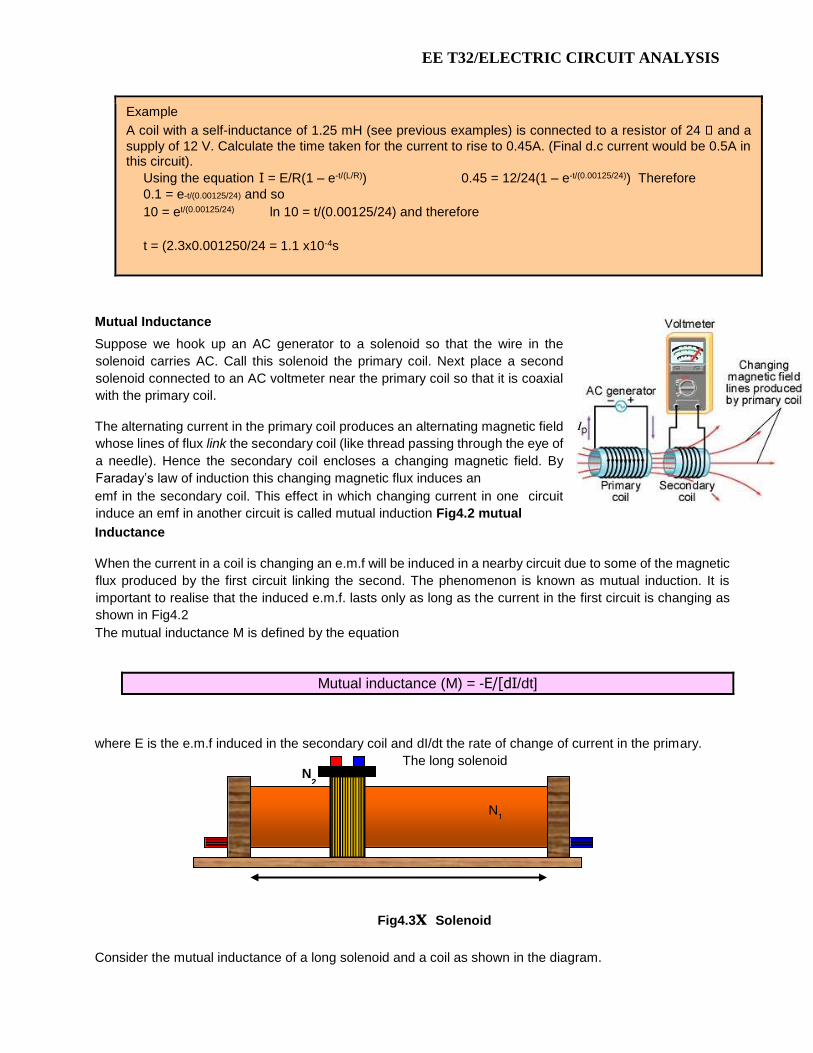
Example
A coil with a self-inductance of 1.25 mH (see previous examples) is connected to a resistor of 24 and a
supply of 12 V. Calculate the time taken for the current to rise to 0.45A. (Final d.c current would be 0.5A in this circuit).
Using the equation I = E/R(1 – e-t/(L/R)) 0.45 = 12/24(1 – e-t/(0.00125/24)) Therefore
0.1 = e-t/(0.00125/24) and so
10 = et/(0.00125/24) ln 10 = t/(0.00125/24) and therefore
t = (2.3x0.001250/24 = 1.1 x10⁻⁴s
Mutual Inductance
Suppose we hook up an AC generator to a solenoid so that the wire in the
solenoid carries AC. Call this solenoid the primary coil. Next place a second
solenoid connected to an AC voltmeter near the primary coil so that it is coaxial
with the primary coil.
The alternating current in the primary coil produces an alternating magnetic field
whose lines of flux link the secondary coil (like thread passing through the eye of
a needle). Hence the secondary coil encloses a changing magnetic field. By
Faraday’s law of induction this changing magnetic flux induces an
emf in the secondary coil. This effect in which changing current in one circuit induce an emf in another circuit is called mutual induction Fig4.2 mutual
Inductance
When the current in a coil is changing an e.m.f will be induced in a nearby circuit due to some of the magnetic
flux produced by the first circuit linking the second. The phenomenon is known as mutual induction. It is
important to realise that the induced e.m.f. lasts only as long as the current in the first circuit is changing as
shown in Fig4.2
The mutual inductance M is defined by the equation
Mutual inductance (M) = -E/[dI/dt]
where E is the e.m.f induced in the secondary coil and dI/dt the rate of change of current in the primary.
Fig4.3x Solenoid
Consider the mutual inductance of a long solenoid and a coil as shown in the diagram.
The long solenoid
N 1
N 2

EE T32/ELECTRIC CIRCUIT ANALYSIS
61
Suppose that a short coil of N2 turns is wound round a solenoid of N1 turns, with a cross-sectional area A,
length x and carrying a current I The flux at the centre of the solenoid is:
Mutual inductance (M) = oAN1N2/x
Example
Calculate the mutual inductance of a pair of coils if the primary has 1000 turns of radius 2 cm and is 1 m long while the secondary has 1200 turns and is wound round the centre of the primary. M = 4π x 10-7x 4 x 10-4 x 1000 x 1200
60 = 1.90x10⁻³ H = 1.90 mH
Let the primary coil have N1 turns and the secondary coil have N2 turns. Assume that the same amount of
magnetic flux 2 from the primary coil links each turn of the secondary coil. The net flux linking the secondary
coil is then N2 2. This net flux is proportional to the magnetic field, which, in turn, is proportional to the current
I1 in the primary coil. Thus we can write N2 2 I1. This proportionality can be turned into an equation by
introducing a constant. Call this constant M, the mutual inductance of the two coils:
N2 2
N2 2 MI1 or M I1
wb
the unit of inductance is henry (H) named after Joseph Henry.
A
The emf induced in the secondary coil may now be calculated using Faraday’s law:
E2 N2 2 N2 2 MI1 M I1
t t t t
I
E2 M 1
t
The above formula is the emf due to mutual induction.
Dot Rule:

EE T32/ELECTRIC CIRCUIT ANALYSIS
Fig4.4 Dot Rule

EE T32/ELECTRIC CIRCUIT ANALYSIS
63

EE T32/ELECTRIC CIRCUIT ANALYSIS
64
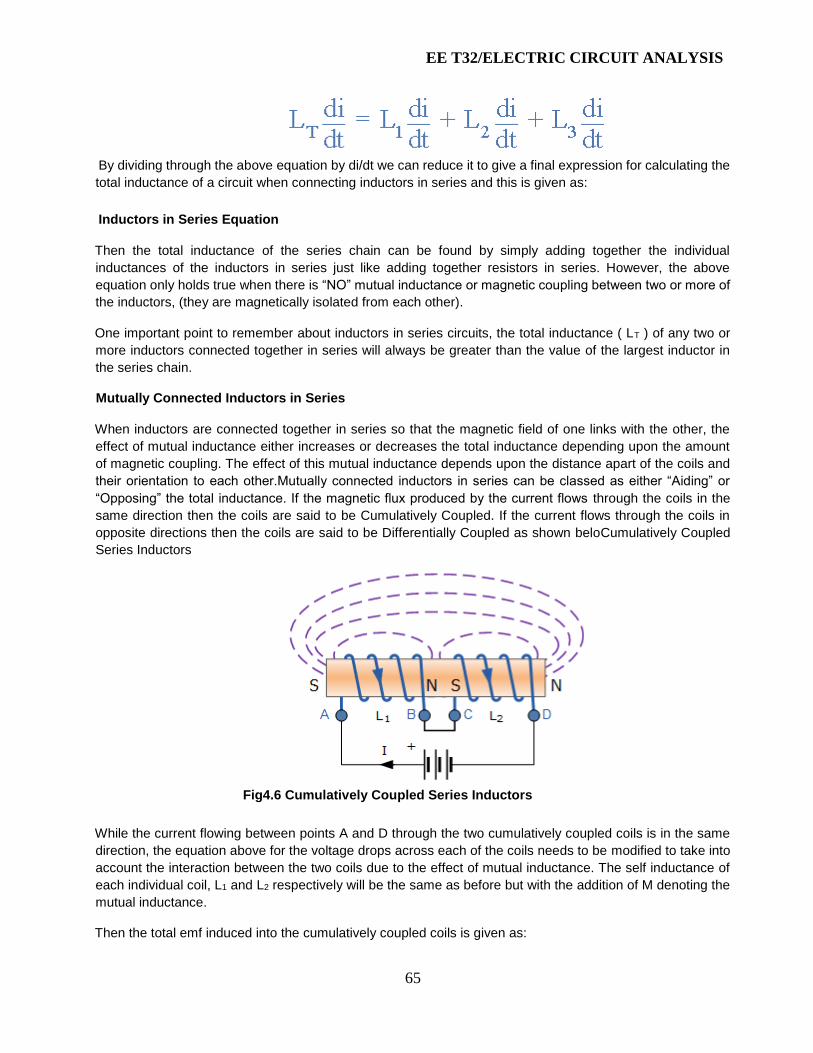
Inductors in Series
Inductors can be connected together in either a series connection, a parallel connection or
combinations of both series and parallel together, to produce more complex networks whose overall
inductance is a combination of the individual inductors. However, there are certain rules for connecting
inductors in series or parallel and these are based on the fact that no mutual inductance or magnetic coupling
exists between the individual inductors as shown in Fig 4.5
Fig4.5 Inductors in Series
The current, ( I ) that flows through the first inductor, L1 has no other way to go but pass through the second
inductor and the third and so on. Then, inductors in series have a Common Current flowing through them, for
example:
IL1 = IL2 = IL3 = IAB …etc.
In the example above, the inductors L1, L2 and L3 are all connected together in series between points A and
B. The sum of the individual voltage drops across each inductor can be found using Kirchoff’s Voltage Law
(KVL) where, VT = V1 + V2 + V3 and we know from the previous tutorials on inductance that the self-induced
emf across an inductor is given as: V = L di/dt.
So by taking the values of the individual voltage drops across each inductor in our example above, the total
inductance for the series combination is given as:
EE T32/ELECTRIC CIRCUIT ANALYSIS
65
By dividing through the above equation by di/dt we can reduce it to give a final expression for calculating the
total inductance of a circuit when connecting inductors in series and this is given as:
Inductors in Series Equation
Then the total inductance of the series chain can be found by simply adding together the individual
inductances of the inductors in series just like adding together resistors in series. However, the above
equation only holds true when there is “NO” mutual inductance or magnetic coupling between two or more of
the inductors, (they are magnetically isolated from each other).
One important point to remember about inductors in series circuits, the total inductance ( LT ) of any two or
more inductors connected together in series will always be greater than the value of the largest inductor in
the series chain.
Mutually Connected Inductors in Series
When inductors are connected together in series so that the magnetic field of one links with the other, the
effect of mutual inductance either increases or decreases the total inductance depending upon the amount
of magnetic coupling. The effect of this mutual inductance depends upon the distance apart of the coils and
their orientation to each other.Mutually connected inductors in series can be classed as either “Aiding” or
“Opposing” the total inductance. If the magnetic flux produced by the current flows through the coils in the
same direction then the coils are said to be Cumulatively Coupled. If the current flows through the coils in
opposite directions then the coils are said to be Differentially Coupled as shown beloCumulatively Coupled
Series Inductors
Fig4.6 Cumulatively Coupled Series Inductors
While the current flowing between points A and D through the two cumulatively coupled coils is in the same
direction, the equation above for the voltage drops across each of the coils needs to be modified to take into
account the interaction between the two coils due to the effect of mutual inductance. The self inductance of
each individual coil, L1 and L2 respectively will be the same as before but with the addition of M denoting the
mutual inductance.
Then the total emf induced into the cumulatively coupled coils is given as:
EE T32/ELECTRIC CIRCUIT ANALYSIS
66
Where: 2M represents the influence of coil L 1 on L 2 and likewise coil L 2 on L 1.
By dividing through the above equation by di/dt we can reduce it to give a final expression for calculating the
total inductance of a circuit when the inductors are cumulatively connected and this is given as:
Ltotal = L 1 + L 2 + 2M
If one of the coils is reversed so that the same current flows through each coil but in opposite directions, the
mutual inductance, M that exists between the two coils will have a cancelling effect on each coil as shown
below.
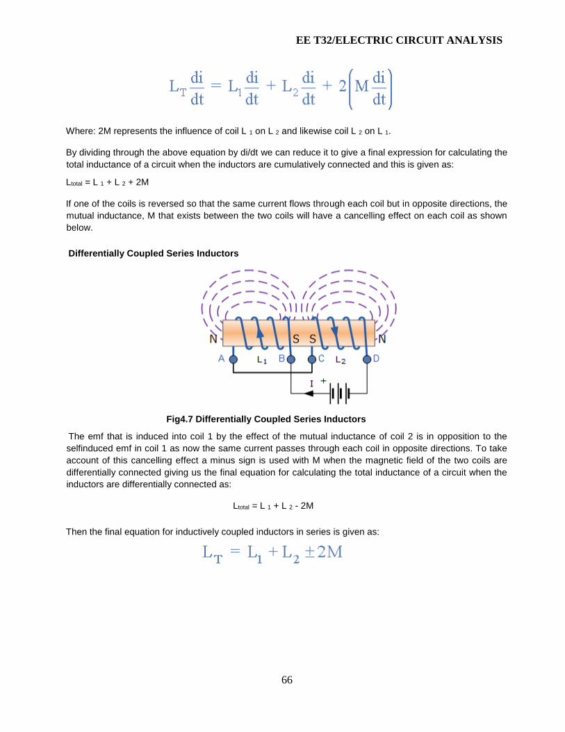
Differentially Coupled Series Inductors
Fig4.7 Differentially Coupled Series Inductors
The emf that is induced into coil 1 by the effect of the mutual inductance of coil 2 is in opposition to the
selfinduced emf in coil 1 as now the same current passes through each coil in opposite directions. To take
account of this cancelling effect a minus sign is used with M when the magnetic field of the two coils are
differentially connected giving us the final equation for calculating the total inductance of a circuit when the
inductors are differentially connected as:
Ltotal = L 1 + L 2 - 2M
Then the final equation for inductively coupled inductors in series is given as:
EE T32/ELECTRIC CIRCUIT ANALYSIS
67
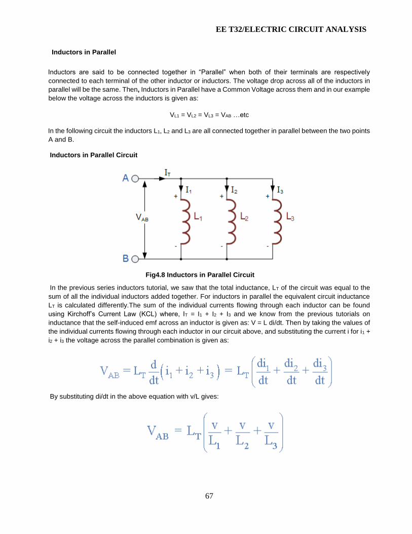
Inductors in Parallel
Inductors are said to be connected together in “Parallel” when both of their terminals are respectively
connected to each terminal of the other inductor or inductors. The voltage drop across all of the inductors in
parallel will be the same. Then, Inductors in Parallel have a Common Voltage across them and in our example
below the voltage across the inductors is given as:
VL1 = VL2 = VL3 = VAB …etc
In the following circuit the inductors L1, L2 and L3 are all connected together in parallel between the two points
A and B.
Inductors in Parallel Circuit
Fig4.8 Inductors in Parallel Circuit
In the previous series inductors tutorial, we saw that the total inductance, LT of the circuit was equal to the
sum of all the individual inductors added together. For inductors in parallel the equivalent circuit inductance
LT is calculated differently.The sum of the individual currents flowing through each inductor can be found
using Kirchoff’s Current Law (KCL) where, IT = I1 + I2 + I3 and we know from the previous tutorials on
inductance that the self-induced emf across an inductor is given as: V = L di/dt. Then by taking the values of
the individual currents flowing through each inductor in our circuit above, and substituting the current i for i1 +
i2 + i3 the voltage across the parallel combination is given as:
By substituting di/dt in the above equation with v/L gives:

EE T32/ELECTRIC CIRCUIT ANALYSIS
68
Parallel Inductor Equation
Here, like the calculations for parallel resistors, the reciprocal ( 1/Ln ) value of the individual inductances are
all added together instead of the inductances themselves.
But again as with series connected inductances, the above equation only holds true when there is “NO” mutual
inductance or magnetic coupling between two or more of the inductors, (they are magnetically isolated from
each other). Where there is coupling between coils, the total inductance is also affected by the amount of
coupling. This method of calculation can be used for calculating any number of individual inductances
connected together within a single parallel network. If however, there are only two individual inductors in
parallel then a much simpler and quicker formula can be used to find the total inductance value, and this is:
One important point to remember about inductors in parallel circuits, the total inductance ( LT ) of any two or
more inductors connected together in parallel will always be less than the value of the smallest inductance in
the parallel chain.
Mutually Coupled Inductors in Parallel
When inductors are connected together in parallel so that the magnetic field of one links with the other, the
effect of Mutual Inductance either increases or decreases the total inductance depending upon the amount
of magnetic coupling that exists between the coils. The effect of this mutual inductance depends upon the
distance apart of the coils and their orientation to each other.Mutually connected inductors in parallel can be
classed as either “aiding” or “opposing” the total inductance with parallel aiding connected coils increasing
the total equivalent inductance and parallel opposing coils decreasing the total equivalent inductance
compared to coils that have zero mutual inductance. Mutual coupled parallel coils can be shown as either
connected in an aiding or opposing configuration by the use of polarity dots or polarity markers as shown
below.
Parallel Aiding Inductors
Fig4.9 Parallel Aiding Inductors
The voltage across the two parallel aiding inductors above must be equal since they are in parallel so the
two currents, i1 and i2 must vary so that the voltage across them stays the same. Then the total inductance,
LT for two parallel aiding inductors is given as:

EE T32/ELECTRIC CIRCUIT ANALYSIS
69
Where: 2M represents the influence of coil L 1 on L 2 and likewise coil L 2 on L 1.If the two inductances are
equal and the magnetic coupling is perfect such as in a toroidal circuit, then the equivalent inductance of the
two inductors in parallel is L as LT = L1 = L2 = M. However, if the mutual inductance between them is zero, the
equivalent inductance would be L ÷ 2 the same as for two self-induced inductors in parallel. If one of the two
coils was reversed with respect to the other, we would then have two parallel opposing inductors and the
mutual inductance, M that exists between the two coils will have a cancelling effect on each coil instead of an
aiding effect as shown below.
Parallel Opposing Inductors
Fig4.10 Parallel Opposing Inductors
Then the total inductance, LT for two parallel opposing inductors is given as:
This time, if the two inductances are equal in value and the magnetic coupling is perfect between them, the
equivalent inductance and also the self-induced emf across the inductors will be zero as the two inductors
cancel each other out. This is because as the two currents, i1 and i2 flow through each inductor in turn the
total mutual flux generated between them is zero because the two flux’s produced by each inductor are both
equal in magnitude but in opposite directions. Then the two coils effectively become a short circuit to the flow
of current in the circuit so the equivalent inductance, LT becomes equal to ( L ± M ) ÷ 2.
Inductors in Parallel
Calculate the equivalent inductance of the following inductive circuit.

EE T32/ELECTRIC CIRCUIT ANALYSIS
70
Fig4.11 Inductors in Parallel
Calculate the first inductor branch LA, (Inductor L5 in parallel with inductors L6 and L7)
Calculate the second inductor branch LB, (Inductor L3 in parallel with inductors L4 and LA)
Calculate the equivalent circuit inductance LEQ, (Inductor L1 in parallel with inductors L2 and LB)
Then the equivalent inductance for the above circuit was found to be: 15mH.
EE T32/ELECTRIC CIRCUIT ANALYSIS
71
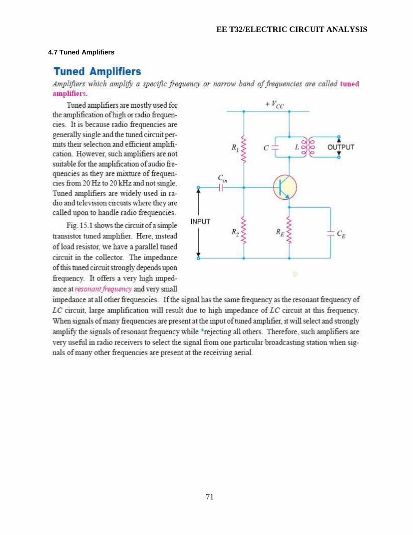
4.7 Tuned Amplifiers

EE T32/ELECTRIC CIRCUIT ANALYSIS
72

EE T32/ELECTRIC CIRCUIT ANALYSIS
73

EE T32/ELECTRIC CIRCUIT ANALYSIS
74
EE T32/ELECTRIC CIRCUIT ANALYSIS
75
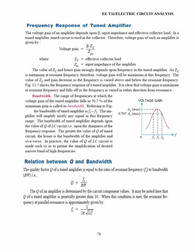
EE T32/ELECTRIC CIRCUIT ANALYSIS
76
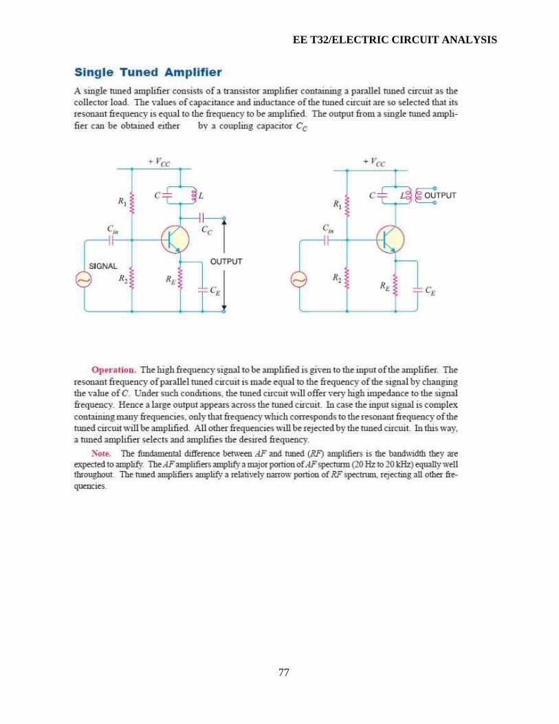
EE T32/ELECTRIC CIRCUIT ANALYSIS
77
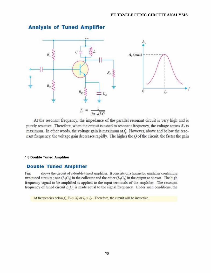
EE T32/ELECTRIC CIRCUIT ANALYSIS
78
4.8 Double Tuned Amplifier
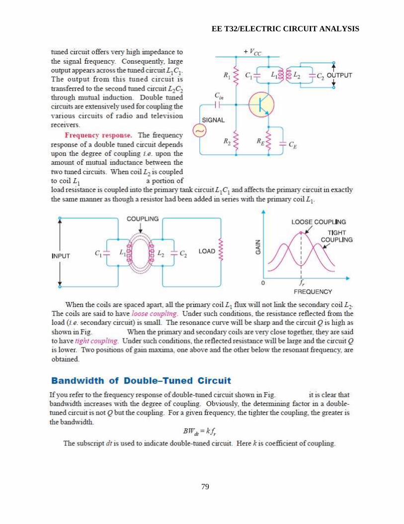
EE T32/ELECTRIC CIRCUIT ANALYSIS
79

EE T32/ELECTRIC CIRCUIT ANALYSIS
80